

Page 1
Cable & Wire Tracer
TraceMeter TM30
User manual v. X1.0
Page 2

1 TM30 User Manual v. X1.0
Page 3

This symbol means that this product should not be discarded with
Instead it should
Waste Electrical and
(WEEE) or according local
regulations. For more information about the separate collection,
please contact your local distributor or
www.vesala.fi
.
Table of contents
1. Overview 3
1.1 General information about cable tracing 3
1.2 Purpose of the device 3
2. TM30 equipment 4
2.1 TM30 basic set-up and accessories 4
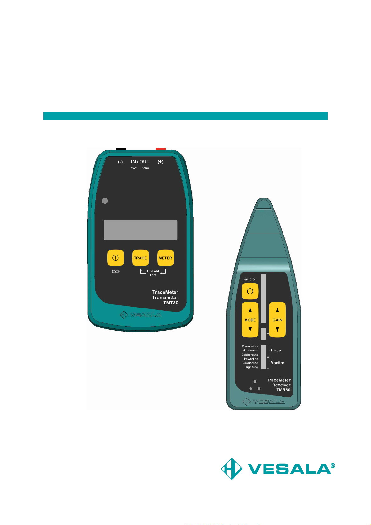
2.2 Transmitter TMT30 5
2.3 Receiver TMR30 6
3. Batteries and warnings for use 7
3.1 Batteries 7
3.2 Transmitter TMT30 warnings 7
3.3 Receiver TMR30 warnings 7
4. Using the transmitter 8
4.1 General 8
4.2 METER mode 8
4.3 DSLAM test 8
4.4 TRACE mode 8
5. Using the receiver 9
5.1 General 9
5.2 Antennas and choosing right mode 9
5.3 Adjusting receiving gain 10
6. Introduction to operating modes 10
6.1 Open wires mode and capacitive antenna 10
6.2 Near cable mode and close range antenna 11
6.3 Cable route mode and rod antenna 12
6.4 Monitor modes 12
7. Practical usage examples 13
7.1 Tracing wire pairs 13
7.2 Tracing underground cables and routes 14
7.3 Tracing cables and wires indoors 16
7.4 Tracing special cables 18
7.5 Floor heating cables and their faults 19
7.6 Tracing cable faults 22
7.7 Tracing tubes and ducts 23
7.8 Using receiver monitor modes 24
8. Technical data, maintenance and service 25
8.1 Technical data 25
8.2 Maintenance, storage and warranty 26
household or general waste after its end-of-life.
be returned for recycling according to EU
Electronic Equipment directive
2 TM30 User Manual v. X1.0
Page 4

1. Overview
1.1. General information about cable tracing
A cable tracer does not locate the actual cable, rather the magnetic or electric field,
which exists in the cable by nature or has been induced to it using the transmitter. As
the shape of the magnetic field depends on other wires and pipes that may be located
near the target object, it is important for the user to be familiar with the properties of the
device as well as possible. We recommend that this manual be read thoroughly prior to
using the TM30 tracer.
1.2. Purpose of the device
With the versatile TM30 cable tracer user can locate telecom and mains cables, antenna
cables, wire pairs, floor heating cables and much more. Device can be operated indoors
out outdoors and it is safe also with live mains targets.
TM30 is designed for:
• Tracing and locating cables
• Tracing single wires and wire pairs
• Spotting short circuits
• Tracing floor heating cable routes
• Identifying communication on wire pairs
• Performing a DSLAM test on digital subscriber lines
• DC and AC voltage metering
• Interference free communication identifying
3 TM30 User Manual v. X1.0
Page 5
2. TM30 equipment
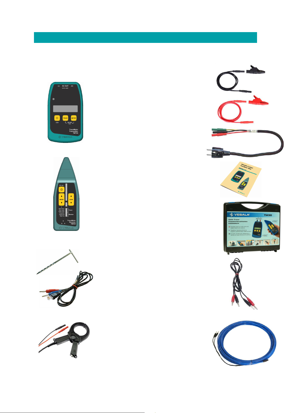
2.1. TM30 basic set-up and accessories
TM30 basic set-up
TMT30 transmitter for galvanic signal
feeding & communication identification
on wire pairs.
TB10m and TB10p CAT-III –feeding
cord (black and red, 1.0m, 4mm safety
banana plugs).
XKKp and XKKm safety crocodile clip
(black and red).
S3TB feeding cord, 0.5m Schuko/ 3
pcs. safety banana plugs.
TMR30 Receiver for receiving the
signal of the transmitter and
monitoring of wires without galvanic
contact.
TM30 User manual
KLTM30 Carrying bag for the ready-
to-use equipment, accessories and
other installation tools (Polypropylene,
approx. 400 x 360 x 90mm).
Accessories
10/TX Groundstake (ground pick)
SJ20 Feeding cord (2.0m, 4mm
standard banana plugs). To be used
with adapters where safety banana
plugs can’t be used.
AP15B cord to connect transmitter to
RJ45 sockets
PM50 (Ø34mm) Clamp-on trans-
former for signal feeding when direct
galvanic connection to cable is not
possible. PM100 (Ø100mm, no
image), larger diameter and higher
output signal.
SPA10 Pipe transmitter antenna for
following e.g. empty electrical piping in
buildings and for locating blockages
within (length 10m).
4 TM30 User Manual v. X1.0
Page 6
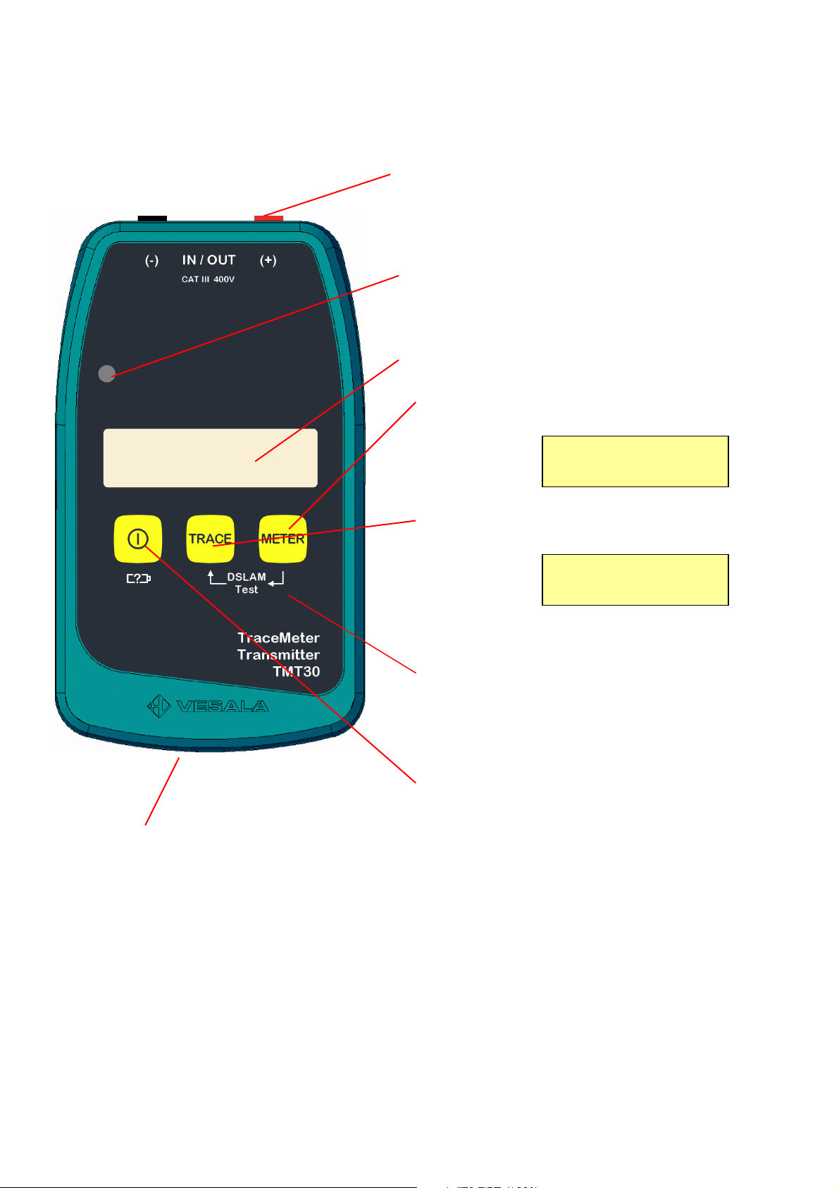
2.2. Transmitter TMT30
LCD
-
display
TRACE 10mA
METER 200kHz
mode for measuring frequency and DC
target object. Displays also output current and
Battery compartment is located at the back of the device. Lid has two
screws. Device operates with six 1.5V LR6 (AA) batteries. Rechargeable NiCd or
NiMH cells can be used too but they have to be charged in a separate charger.
If batteries are low, a BATTERY LOW text blinks on LCD.
Figure 2.2. TMT30 user interface
IN/OUT connectors:
2 pcs. 4mm safety banana jacks for
signal feeding and metering functions.
Light sensor for LCD backlight
automatic intensity adjustment.
METER
and AC voltages of the target object.
TRACE mode for feeding tracing signal to the
target DC and AC voltage.
A long press activates or deactivates the
CONT. BEEP continuity indicator.
DSLAM Test:
Test starts by keeping METER button pressed
and simultaneously pressing TRACE button
briefly.
Power button:
To switch the device on and off. LCD will
display battery voltage while start-up or if
Power button is pressed briefly during use. A
long press during start-up prevents automatic
+48.0V ~0.0V
-48.0V ~1.0V
5 TM30 User Manual v. X1.0
Page 7
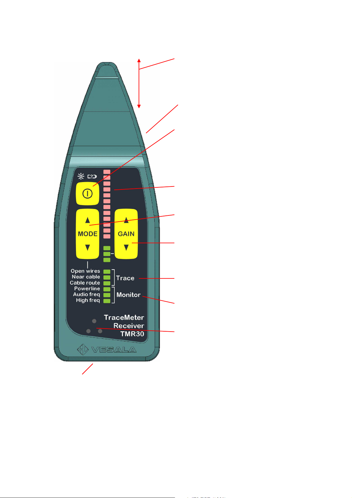
2.3. Receiver TMR30
Use these up & down buttons to choose suitable
Battery compartment is located at the back of the device. Lid has two
screws. Device operates with four 1.5V LR3 (AAA) batteries. Rechargeable NiCd
or NiMH cells can be used too but they have to be charged in a separate
charger. If batteries are low, active MODE LED will blink.
Figure 2.3. TMR30 user interface
Nose section with antennas :
Nose has three integrated antennas:
Capacitive antenna for Monitor modes
and Open wires mode, close range
antenna for Near cable mode and rod
probe for Cable-route mode.
Work light:
The LED light under the nose turns on and off
by briefly pressing Power button.
Power button:
To switch the device on and off. Level bar will
display battery level while start-up or if Power
button is pressed briefly during use. Device
always starts to the same mode that was used
the previous time. A long press during start-up
Level bar:
LED bar display for indicating receiving signal
strength.
MODE buttons:
Use these up & down buttons to choose the
right Trace or Monitor mode.
GAIN buttons:
receiving sensitivity at which signal audio and
Level-bar won’t get overdriven.
Trace modes are for receiving signals
generated by the transmitter. One of three
LEDs displays which mode is active.
Monitor modes are to monitor signals other
than those generated by the transmitter. One
of three LEDs displays which mode is active.
Speaker for indicating received tracing signal
sound and for internal sound signals & beeps.
6 TM30 User Manual v. X1.0
Page 8
3. Batteries and warnings for use
3.1 Batteries
TMT30 transmitter uses 6 pcs. 1.5V LR20 (size AA, Mignon) alkaline batteries and
TMR30 receiver 4 pcs. 1.5V LR03 (size AAA) alkaline batteries. Both have a battery
compartment at the back of the device, under a lid with two screws.
If a there is Battery Low message on TMT30 LCD or the active mode LED of TMR30
blinks, batteries are weak and should be replaced to ensure the optimal functioning of
the equipment. If batteries are very low, devices turn automatically off to avoid battery
leaking.
Rechargeable NiCd or NiMH cells can be used too but they have to be charged in a
separate charger.
3.2 WARNINGS CONCERNING THE TRANSMITTER
When operating with mains targets, always use contact proof and right
safety class cords and adapters, and follow safety instructions.
Transmitter may be connected to max. 400V rms voltage!
If either transmitter output terminal is connected to a live target,
dangerous voltage or current may appear on wires connected to the other
output, unless they are properly grounded.
Avoiding interference with telecommunication or electric network is
always the responsibility of the user.
Danger of electric shock: Always disconnect feeding cords before opening
the battery lid or enclosure.
3.3 WARNINGS CONCERNING THE RECEIVER
Though the receiver nose section is electrically safe to the user up to
600V, we do not recommend using the receiver so that the nose touches
live targets.
Never expose other parts of the enclosure to direct contact to mains
wires or other live objects.
Always follow safety instructions when working with live mains objects.
Caution! Do not use TMR30 to verify if an object is live or not!
7 TM30 User Manual v. X1.0
Page 9

METER 200kHz
DSLAM TEST
DSLAM FOUND
Battery OK 9.0V
Vesala TMT30
TRACE 10mA
4. Using the transmitter
4.1 General
TMT30 will always start to the same mode (METER tai TRACE)
that was used the previous time. LCD will display battery
voltage while start-up and during operation user can check
battery level by pressing Power button briefly.
Device displays firmware (software) version as long as Power
button is held down during start-up.
IN/OUT connectors are connected to the target object with the TB10m and TB10p
feeding cords and a suitable adapter or safety crocodile clips or with the S3TB feeding
cord to Schuko socket. Always ensure electrical safety when connecting the device.
Device will automatically switch-off after three hours, unless buttons are pressed in the
mean time. To prevent the automatic switch-off, press the Power button for 2 seconds
during start-up until a ti-ti sound is heard.
4.2 METER mode
In METER mode transmitter does not send anything, nor does it disturb e.g. possible
data transmission in the target object. Transmitter only measures the target voltages
and frequencies, much like a multimeter.
LCD upper right corner displays detected frequency. The lower
row of LCD displays both DC and AC voltages. Device sustains
max. 400V mains voltage.
4.3 DSLAM test
With DSLAM TEST user can check whether there is an
exchange side DSL modem (DSLAM) present on the line.
During test TMT30 sends a handshake request to the line and
waits for an answer from an ADSL or VDSL DSLAM.
DSLAM TEST starts by keeping the METER button pressed and
simultaneously pressing TRACE button briefly. Test will take
max. 15 seconds during which LCD displays DSLAM TEST.
Then either DSLAM FOUND or DSLAM NOT FOUND message
is displayed and after that device will automatically resume METER mode.
4.4 TRACE mode
In TRACE mode device constantly transmits a 125kHz signal to the target connected to
the IN/OUT connectors.
LCD upper right corner displays output current, which depends
on target impedance. Second row displays both DC and AC
voltages.
If output current exceeds 1mA, device makes a beep sound. If the CONT. BEEP
continuity indicator is set active, beep is continuous. CONT. BEEP setting can be
activated (On) or deactivated (Off) with a long press of TRACE button.
0.0V ~1.1V
FW: X1.0A 100000
+48.0V ~0.0V
0.0V ~0.5V
0.0V ~0.0V
-48.0V ~1.0V
8 TM30 User Manual v. X1.0
Page 10

5. Using the receiver
5.1 General
TMR30 starts when Power button is pressed until a beep sound is heard. Level bar will
display battery level while start-up; the higher LED bar, the higher is battery voltage.
If Power button is pressed briefly during use, the work light under the nose turns on
and Level bar displays battery level just like during start-up. Work light turns off by
pressing Power button again or by shutting down the device.
TMR30 Receiver has six operating modes, which
have been divided into two categories: Trace
modes are to be used for receiving signals
generated by the TMT30 transmitter. Monitor
modes are used for monitoring signals other than
generated by the transmitter.
Device always starts to the same mode that was used the previous time and one of
MODE LEDs will display which mode is active. MODE up & down buttons are used to
change mode.
Device will automatically switch-off after 20 minutes, unless buttons are pressed in the
mean time. To prevent the automatic switch-off, press the Power button for 2 seconds
during start-up until a ti-ti sound is heard.
5.2 Antennas and choosing right mode
There are three integrated antennas inside the TMR30 nose
section and device automatically chooses one of them
according to the user-selected mode:
- Capacitive antenna is right at the tip of the nose
where it has best possible accuracy.
- Inductive close range probe is located under the small
grooves seen on the top and bottom of the nose. The
grooves point the most sensitive spot of the antenna.
- Inductive rod probe is located in the middle of the
nose and its most sensitive direction is the same as
the nose direction.
Trace modes – Choose one of these three modes according to the target object:
- Open wires (capacitive antenna): For wire pairs and other uncovered conductive
objects when distance is <20cm.
- Near cable (close range probe): For wires and cables when distance is <40cm.
- Cable route (rod probe): For tracing conductive objects inside walls or tracing
underground cables.
Monitor modes – Choose one of these three modes according to the target object:
- Powerline: For tracing and locating live mains wires and cables inside walls etc.
- Audio freq: For listening audio frequencies e.g. on wires or close to electrical
appliances.
- High freq: For monitoring high frequencies such as DSL, PCM etc.
All Monitor modes use the capacitive antenna.
9 TM30 User Manual v. X1.0
Page 11

5.3 Adjusting receiving gain
Receiving gain (sensitivity) can be adjusted with the 3-step GAIN adjustment and GAIN
LEDs display which gain setting is on. It is recommendable to use gain, which makes the
Level bar height to be approx. in the middle; that way changes in signal strength are
easiest to notice.
Level bar displays target location either as maximum signal (e.g. wire pairs) or minimum
(e.g. cable tracing). Audio signal strength from the speaker is dependant of the GAIN
setting too.
6. Introduction to operating modes
Tracing a cable or wire or another object is always based on detecting the electric field
(capacitive tracing) or the magnetic field (inductive tracing) of a conductive object. These
basics are common to all tracing so understanding them is vital.
6.1. Open wires mode and capacitive antenna
As the name suggests, Open wires mode is intended for close range tracing of open
(disconnected) wires and pairs and other conductive objects. Wires that are under a
shield or deep inside other structures can’t be traced with this mode. Open wires mode
works relatively close to the target, usually less than 20cm, and it is best with wire & pair
identification and tracing.
Depending on the situation, transmitter is connected either to the traced wire pair or
between one wire and grounding. When the receiver nose tip (i.e. the capacitive
antenna) is close to the target, Level bar rises accordingly and loud signal can be heard.
The direction of the nose has almost no significance, as the shape of the capacitive
antenna sensitivity area is spherical (ball shaped), as shown in below figure. Figure
shows also the typical shape of the capacitive field generated by a single wire.
Figure 6.1. Capacitive antenna sensitivity area shape in Open wires mode (left)
and typical shape of a capacitive field (right).
10 TM30 User Manual v. X1.0
Page 12

6.2 Near cable mode and close range probe
Near cable is a very versatile mode. It can be used to trace wires and cables up to 40cm
distance and even inside structures or big bunch of wires or cables. Near cable mode
works nicely when open (unconnected) cross connection wires need to be traced or when
telecom pairs, electric wiring or antenna cables need to be located and traced.
Near cable mode is based on inductive tracing in which a magnetic field created by a
current running in a wire is detected with the TMR30 close range antenna. The stronger
the current, the higher Level bar display and louder the signal can be heard with the
receiver. Usually there is however a precise minimum point when the close range probe
is right above the right wire or cable.
The location of the close range probe and also
the most sensitive receiving area is marked
with the small grooves on the top and bottom
of the nose. This also means that in Near
cable mode the sensitivity is best at the top or
bottom of the nose, not at the tip of the nose,
as seen in the figure to the right.
Figure 6.2.a. The sensitive area of the close range probe in Near cable mode.
Due to the specific directional field shape of Near cable mode, receiver nose has to be
taken close to the target wire or cable so that either the top or bottom side groove
marked sensitive spot is closest to the target, as seen in the below figures. Figures show
also the minimum point when the close range probe is right above the right wire or
cable.
Figure 6.2.b. Two right ways and one wrong way how to use receiver in Near
cable mode and corresponding field shapes with the minimum spot.
11 TM30 User Manual v. X1.0
Page 13

6.3 Cable route mode and rod probe
Cable route mode is intended for tracing cables and tubes even underground.
Also Cable route mode is based on inductive
tracing in which a magnetic field created by a
current running in a wire is detected with the
TMR30 rod antenna. Stronger current gives
higher signal and longer detection distance.
There is however a precise minimum point right
above the right wire or cable.
Rod antenna is very unilateral, i.e. it has very
sharp and narrow sensitive area pointing to the
direction of the nose, as shown in the figure to
the right.
Figure 6.2.a. The sensitive area of rod probe in Cable route mode.
When using Cable route mode it is recommendable to keep the receiver all the time in
upright position towards the target, as in the two figures below. Pendulous moving
(rightmost figure) may detect minimum spots caused by return currents or other cables
and hence mislead the user to wrong conclusion.
Figure 4.2.b. Right and wrong ways to use receiver in Cable route mode and
corresponding field shapes and the minimum spot of a straight wire.
6.4 Monitor modes
TMR30 offers three monitoring modes to identify communication signals on wires and
signals generated by e.g. electric appliances. These modes use the capacitive antenna,
so the most sensitive area is at the tip of the TRM30 nose. The direction of the nose has
little significance, as the capacitive antenna sensitivity area is spherical (ball shaped)
with no minimum spots etc, as shown earlier in figure 6.1.
Powerline mode is intended for tracking 50-60Hz mains wires e.g. inside walls and also
to identify phase connector of a wall socket like with a mainstester.
Audio freq mode monitors audio frequencies up to 10kHz on wires or e.g. on electric
appliances. As audio signal fields are by nature very weak, TMR30 nose must be as close
to the target as possible.
High freq mode is for tracing frequencies over 10kHz on wires or terminals. E.g. DSL
signals can be detected with this mode.
12 TM30 User Manual v. X1.0
Page 14

7. Practical usage examples
In this paragraph there are two symbols used to describe grounding & earth connection:
This symbol means grounding through constructions, such as grounded pipes,
metal chassis, mains wall socket protective earth connector etc.
This symbol means direct earthing to soil with a ground pick or other similar
means so that no other constructions are involved.
7.1 Tracing wire pairs
7.1.1 Cross connection pairs
Task: Unused or active pair needs to be traced at cross connection
terminals.
- Connect transmitter to the traced pair. Transmitter shows possible voltage and
frequency on pair.
- Choose Open wires mode with receiver and move receiver nose close to the
wire bunch along the cross connection rack.
- When the right terminal block is found, strongest signal can be heard above the
right pair when distance is <5cm.
- If possible verify the result by short-circuiting the pair: signal should disappear.
Task: Unused (open) pair needs to be traced at cross connection racks
without knowing its route or ending area.
- Short-circuit the traced pair wires at the starting point. Connect transmitter
between the shorted pair and grounded cross connection rack.
- Choose Near cable mode with receiver. Scan the wire bunches on the rack
shelves with the receiver nose. Right bunch gives strongest signal.
- Follow the right bunch to the correct terminal block or to the open wire ends.
Receiver gain often needs to be adjusted lower when the right pair gets closer.
13 TM30 User Manual v. X1.0
Page 15

7.1.2 Tracing wires pairs at cable ends or joints
Task: A pair needs to be recognized at the end of an open cable or joint.
- Connect transmitter to the traced pair.
- Choose Open wires mode with receiver and move receiver nose close to the
exposed wires.
- Right pair gives the strongest signal. If the wires ends of the right pair are apart
enough from each other, a signal minimum can be detected between the wires.
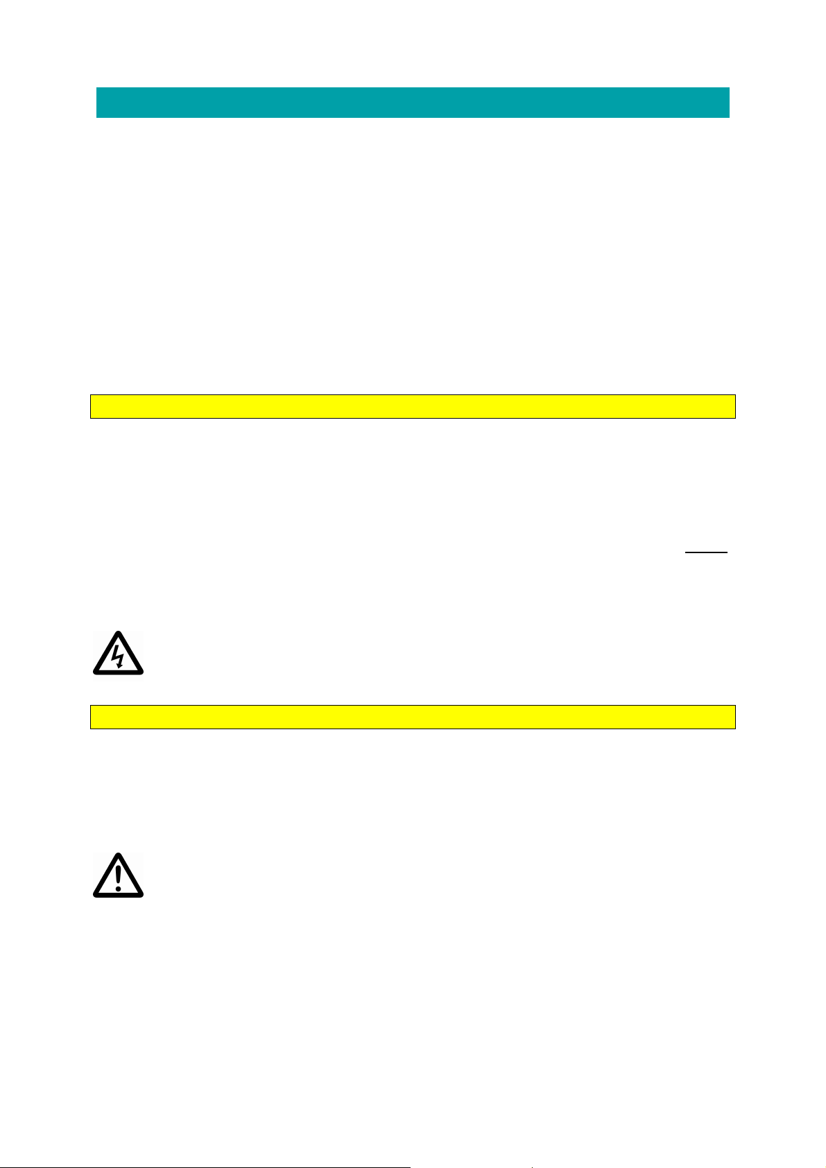
7.2 Tracing underground cables and routes
7.2.1 Neutral electric cables and telecom cables
Task: The route of a neutral electric cable or telecom cable must be
traced above ground.
- Connect one transmitter output terminal to one or more wires of the cable. Often
better tracing result is achieved if the same wires are grounded at the other end.
- Connect transmitter second output terminal to a good grounding. If possible, use
ground pick and press it deep into damp soil for best earth connection.
- Choose Cable route mode with receiver.
- Trace the cable route by following the signal minimum in the receiver nose
direction.
- To determine cable depth (h), turn the receiver to 45°
angle right above ground and trace until a second
minimum is found perpendicular to the cable route.
Cable depth is same as the distance (d) between the
two minimums, as shown in the figure.
14 TM30 User Manual v. X1.0
Page 16
7.2.2 Live mains cables
Task: The route of a live electric cable must be traced above ground.
- Connect one transmitter output terminal to the protective earth wire of the cable
or e.g. to a wall socket PE contact. If the task is to trace the feeder cable of a
metallic light pole, transmitter can be connected to the earthed pole itself.
- Connect transmitter second output terminal to a good grounding as far as
possible from the transmitter using a ground pick and press it deep into damp
soil for best earth connection.
- Choose Cable route mode with receiver.
- Trace the feeding cable route by following the signal minimum in the receiver
nose direction.
7.2.3 Cables that can’t be reached for galvanic feeding
Task: The route of a live or neutral cable must be traced above ground
but cable ends can’t be reached.
- Connect transmitter to a clamp-on transformer such as PM50 or PM100. Place
the clamp around the cable in a place where the cable is visible.
- Choose Cable route mode with receiver.
- Trace the cable route by following the signal minimum in the receiver nose
direction. This method requires that cable is grounded at both ends.
15 TM30 User Manual v. X1.0
Page 17

7.3 Tracing cables and wires indoors
7.3.1 Live and neutral electric cables
To connect transmitter to live targets, always use proper contact proof safety
class cords and adapters and follow safety instructions.
WARNING! If either transmitter output terminal is
connected to a live target as shown in the figure,
dangerous voltage appears on wires connected to
the other output as well, unless they are properly
grounded.
Task: The route of a live or neutral cable must be traced from a short
distance, e.g. inside walls or on cable shelves.
- Connect transmitter to the Schuko wall socket neutral (N) and protective earth
(PE) contacts (not to phase contact) with S3TB cord’s corresponding wires.
- Same method applies to situations where cable is disconnected or a fuse has
been blown.
- Choose Near cable mode with receiver. Trace the cable route by following the
signal maximum. Right above the cable there is often a signal minimum.
Task: The route of a live or neutral cable must be traced from a longer
distance, e.g. near roof or on cable shelves which can’t be reached.
- Connect one transmitter output terminal to a neutral wire of the cable and the
second output terminal to a good grounding, preferably using a ground pick for
best earth connection.
- Choose Cable route mode with receiver.
- Trace the cable route by following the signal minimum in the receiver nose
direction. This method usually enables tracing up to two metres distance. Closer
to the cable it’s possible to use Near cable mode with receiver as well.
- If cable’s wires are disconnected at the other end, signal gets weaker along the
path with Cable route mode. In that case it is recommendable to change to
Near cable mode and close range tracing. Closer to the end, signal minimum
gradually disappears and there is only a signal maximum above the right cable.
16 TM30 User Manual v. X1.0
Page 18

7.3.2 Wall sockets and circuit breakers & fuses
Task: Electronic circuit breaker for a certain live wall socket needs to be
located at the electrical panel or cabinet.
- Connect transmitter to the Schuko wall socket between phase (P) and either
neutral (N) or protective earth (PE) contacts with the S3TB cord respective
wires.
- Choose Near cable mode with receiver. If necessary, the route of the cable can
be traced as shown in paragraph 7.3.1.
- At the electrical panel it is highly recommended to use the receiver so that the
nose top side groove marked sensitive spot is closest to the fuses, not the nose
tip, as seen in the figures below.
- First, track all circuit breakers which give a strong signal. It is normal that
several circuit breakers give a signal, as they are parallel connected via their
phase rail.
- The right circuit breaker usually has a very strong signal and there is a sharp
minimum in the middle, which distinguishes it from other circuit breakers.
- If the right circuit breaker is turned off, signal level decreases significantly. In
this case the signal can however be detected with Open wires mode as well
(see the next example).
- Signal behaviour and receiver usage are somewhat different with ceramic fuses
with respect to electronic circuit breakers. Therefore it is recommendable to
practise receiver use beforehand with known fuses/breakers.
NOTE! Parallel wall sockets with loads such as heaters or lights will
cause transmitter current spread to other directions than towards the
circuit breaker, which may affect locating the right circuit breaker.
Task: A turned-off electronic circuit breaker or removed fuse base for a
neutral wall socket needs to be located at the electrical panel or cabinet.
- Connect transmitter to the Schuko wall socket between phase (P) and neutral
(N) contacts with the S3TB cord respective wires.
- With receiver choose either Near cable mode (remember to direct the nose top
side groove towards the circuit breakers) or Open wires mode (point the tip of
the nose towards the circuit breakers).
- Above the right circuit breaker there is a strong signal but no minimum. Other
circuit breakers usually have no signal.
17 TM30 User Manual v. X1.0
Page 19

7.3.3 Electric cables which can’t be galvanically connected
Task: The route and end of a cable from a cabinet needs to be located
without disconnecting the cable or opening the cabinet.
- Connect transmitter with a clamp-on transformer (PM50 or PM100) to the
cable at a place where the cable is visible. Note that using a clamp-on
transformer always requires that the near end of the cable is grounded.
- If cable is reachable, choose Near cable mode with receiver. If the other end of
the cable is grounded, trace the right cable by finding strongest signal, which
has a sharp minimum right above it. Even Cable route mode may work,
enabling tracing up to two metres distance.
- If cable’s wires are disconnected at the other end, usually no minimum can be
detected but tracing is possible by following the strongest signal with Near
cable mode or Open wires mode.
7.4 Tracing special cables
7.4.1 Coaxial cables and other shielded cables
Task: Route of a coaxial cable needs to be traced on cable shelves.
- Connect one transmitter output terminal to the coaxial cable shield. Make sure
that the shield is not grounded at this end (other end may be grounded or not)
- Connect transmitter second output terminal to a grounding, e.g. to a nearby wall
socket protective earth (PE) contact.
- If cable is reachable, choose Near cable mode with receiver. If the other of the
cable is grounded, trace the right cable by finding strongest signal, which has a
sharp minimum. If cable’s wires are disconnected at the other end, usually no
minimum can be detected but tracing is possible by following the strongest
signal with Near cable mode or Open wires mode.
- If the other end of the cable is grounded, even Cable route mode may work,
enabling tracing up to two metres distance by following the signal minimum in
the receiver nose direction.
18 TM30 User Manual v. X1.0
Page 20

7.4.2 Generic cabling systems (data cables and RJ45 sockets)
Task: Route of one generic cabling system cable needs to be traced.
- Connect one transmitter output terminal to one wire or pair of the traced cable
RJ45-socket.
- Connect transmitter second output terminal to grounding such as the protective
earth (PE) contact of a wall socket. Note that the wall socket feeding cable must
not run the same route as the traced cable.
- Choose Near cable mode with receiver. Trace the right cable on shelves or
cable ducts by finding strongest signal, which has a sharp minimum when
receiver nose top or bottom side groove is right above the cable.
- You may also try Cable route mode and trace the cable route by following the
signal minimum in the receiver nose direction.
Task: Terminating socket of a generic cabling system cable needs to be
tracked at distribution cabinet.
- Connect transmitter to one pair of the RJ45-socket of the corresponding cable.
- Choose Open wires mode with receiver. At the distribution cabinet insert
receiver nose into each potential RJ45-socket as deep as it fits; right socket
gives the strongest signal.
- Generic cabling system minimizes electromagnetic leakages by nature and signal
can be heard only from a very close distance. Therefore try to get the receiver
nose as deep into the RJ45 socket as possible.
7.5 Floor heating cables and their faults
7.5.1 Typical reasons to floor heating faults
Mistakes during assembly
- Cable has been damaged during assembly after which it has worked for some
time but heating current has gradually burned the conductors, resulting in an
open or short-circuit fault. There may be several faults in the same cable.
- Cable runs through a so-called air pocket in the concrete mass, causing cable
over heating and eventually an open or short-circuit.
Damages caused by later reasons
- Cable has been exposed to pressure due some renovation work at the area,
resulting in a latent but developing damage.
- Holes have been drilled to the floor causing immediate or developing damage.
- The floor structure has changed, e.g. fallen down, causing cracks and damage to
cable.
19 TM30 User Manual v. X1.0
Page 21

7.5.2 Preliminary inspection of the target area
As a first step it is always recommendable to perform a systematic inspection at
the cable assembly area, assembly method as well as fault type.
When and how the fault appeared
- Did it blow a fuse (short circuit)
- Did the cable just stop heating (cut cable)
- Did a residual current device trip (ground leak)
- Have there been renovation or other changes going on at the target area, such
as added furniture or drilled holes before the fault. As faults may appear quite a
long time afterwards, knowledge of previous renovation history may help too.
Measure cable resistances and capacitances
- Make sure that cable wires are not live and disconnect all from the feeding cable.
- Measure resistances and capacitances between all heating cable wires and shield
and compare them to normal values of an intact cable:
o Phase / neutral
o Phase / protective earth
o Neutral / protective earth
- As it possible that heating cable is shorted to concrete reinforcement, it is worth
measuring all wires against the building’s earthing too.
- Resistance values usually reveal the fault type and which wires are affected.
Capacitances may help defining the fault distances from the measuring point.
Define the heating cable route
- Follow the route of the heating cable from start to end as explained in paragraph
7.5.3 and carefully mark the route on floor. Often the exact route may reveal
faults due to bad assembly or later renovations, such as:
o Cable has been placed under fixed furniture like closets
o Sauna stove or bench screws have been inserted too close to the cable
o Toilet seat screws hit the cable route
- If the fault can’t be determined by following the route only, it is necessary to try
to find spots along the route where the tracing signal level suspiciously changes
(see paragraph 7.5.3):
o In case of a short circuit, signal usually can be followed till the fault spot
where it get stronger and then quickly weakens or disappears.
o In case of an open circuit, signal usually starts to weaken starting from the
fault spot, but change is less distinct.
7.5.3 Tracing floor heating cables and their faults
Task: Floor heating cable route needs to be traced e.g. for defining a
fault location or for drilling holes to safe spots.
- Make sure that cable wires are not live and disconnect all from the feeding cable.
- There are two possible methods to trace the cable route and it depends on the
target which one works best.
- It is advisable to mark the route to the floor with chalk or tape.
20 TM30 User Manual v. X1.0
Page 22

Near cable method
- Connect transmitter between the cable’s phase (L) and neutral (N) wires.
- Choose Near cable mode with receiver. Use the receiver in upright position or
upside down as in the figure, so that either nose groove spot is close to the floor.
- Trace the cable route by following the signal minimum.
- It is usual that changes in cable depth and cable’s back and forth looping affect
how clearly the minimum can be detected.
Cable route method
- Connect one transmitter output terminal to the cable shield and second output to
a good grounding, e.g. to the feeding cable’s protective earth PE wire.
- Choose Cable route mode with receiver. Trace the cable route by following the
signal minimum in the receiver nose direction.
- Cable route method works better especially with cables that have an open fault
(cut wire).
Task: A short circuit in a floor heating cable needs to be traced.
- Connect transmitter between the shorted wires of the cable (in the below figure
phase and neutral are shorted). Leave the third wire unconnected.
- Choose Near cable mode with receiver. Again, use the receiver upside down, so
that its nose topside groove marked spot is close to the floor.
- Monitor signal strength along the cable route. At fault spot signal gets stronger
and then quickly weakens or disappears.
21 TM30 User Manual v. X1.0
Page 23

Task: An open in a floor heating cable needs to be traced.
- Several factors affect tracing an open in a heating cable, such as what cable type
is at hand, is the cable fully cut or just one wire and what kind of grounding
there is to concrete reinforcement. All these require carefulness while tracing
and yet it is possible that exact fault location can’t be determined.
- When the cable route has been traced, connect one transmitter output terminal
to the cut wire. Connect the second output to the remaining two wires parallel
(in the figure shielding i.e. protective earth and the neutral wire) and connect
both of them also to a good grounding, preferably using a ground pick to ensure
best earth connection and minimum return current interference.
- Check transmitter output current level: the higher current, the further is the cut
fault from the transmitter.
- Choose Near cable mode with receiver. Again, use the receiver upside down, so
that its nose topside groove marked spot is close to the floor.
- Monitor signal strength along the cable route. In this case signal is typically weak
and no minimum can be detected. At fault spot signal gets even weaker.
7.6 Tracing cable faults
7.6.1 Location of a short circuit fault
Task: Cable has a short circuit fault which location needs to be traced.
- Connect transmitter between the shorted wires of the cable.
- Choose Near cable mode with receiver. Monitor signal strength around the
cable surface. At fault spot signal gets stronger and then quickly disappears.
- Low-ohmic short-circuit faults are easier to find. Shorts, which are caused by
water in a cable, are harder to find and result depends on how wet the cable is.
- Ground leaks and shorts or shorts from wires to cable jacket are traced similarly.
22 TM30 User Manual v. X1.0
Page 24

7.6.2 Location of a open wire (cut fault)
Task: Cable has a open (cut fault) which location needs to be traced
- Connect one transmitter output terminal to the open wire. Connect second
output parallel to the remaining wires (e.g. with mains cable) and possible
shielding and all of them finally to a good grounding, preferably using a ground
pick to ensure best earth connection.
- With shielded cables choose Near cable mode with receiver. With unshielded
cables Open wires mode may also work.
- Monitor signal strength around the cable surface. At fault spot signal quickly
weakens or disappears. With Near cable mode no minimum can be detected.
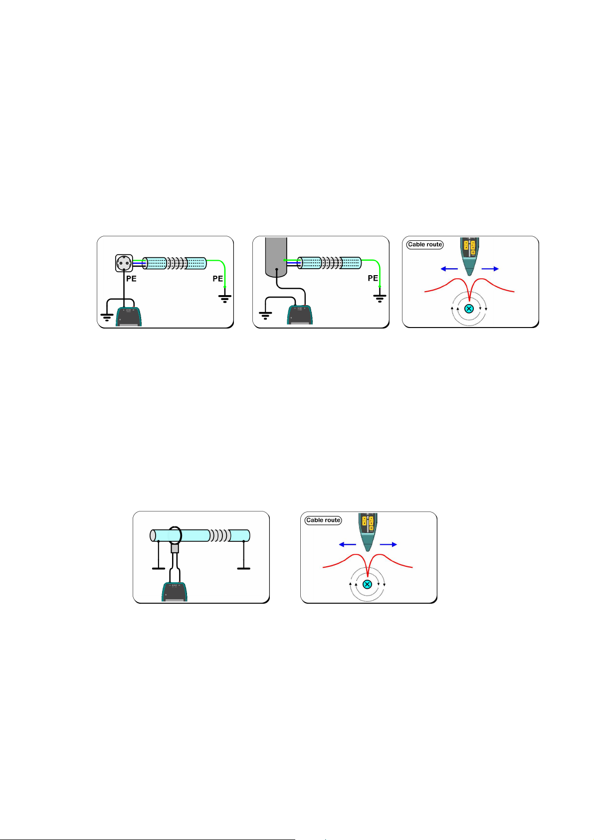
7.7 Tracing tubes and ducts
7.7.1 Conductive tubes and ducts inside walls or under ground.
Task: The route of a metallic tube needs to be traced under ground or
inside wall.
- Connect one transmitter output terminal to the tube and the second output
terminal to a good grounding using a ground pick which is inserted to the soil as
far as possible from the tube.
- Choose Cable route mode with receiver.
- Trace the tube route by following the signal minimum in the receiver nose
direction.
- With tubes that are inside walls it is possible to use Near cable mode with
receiver as well.
23 TM30 User Manual v. X1.0
Page 25

7.7.2 Non-conductive pipes inside walls etc.
Task: The route of a non-conductive tube or possible tube blockage
needs to be traced inside wall.
- Use the 10m long SPA10 pipe transmitter antenna accessory, which is inserted
into the tube such as an electrical pipe.
- If there is a blockage in a tube which needs to be located, connect both
SPA10 terminals to the transmitter and push the antenna into the tube until it
hits the blockage.
- Choose Cable route mode with receiver. The SPA10 head is located where
there is a longitudinal minimum and transversal maximum in the signal strength
(see closer instructions in the SPA10 manual).
- If the route of a tube is to be traced, connect one transmitter output terminal
to both SPA10 terminals (parallel) and the second output terminal to a
grounding, e.g. to a wall socket protective earth PE contact.
- Choose Near cable mode with receiver. Trace the tube by following the signal
minimum. If necessary, use the receiver upside down.
7.8 Using receiver monitor modes
7.8.1 Powerline mode (”mains tester”)
Task: Mains wall socket phase contact needs to be recognized or mains
wires inside walls need to be located.
- In Powerline mode receiver can be used without transmitter e.g. as a mains
tester: Scan the wall socket (Schuko) and its contacts with the receiver nose tip:
Strongest signal can be heard closest to the phase (L) contact, but there is a
smaller signal above Neutral (N) and protective earth (PE) contacts too.
- To locate mains wires inside walls, use Powerline mode to scan wall surface
with the receiver nose. There are usually many mains related fields indoors, so is
recommendable to keep receiver gain low to be able to find wires.
24 TM30 User Manual v. X1.0
Page 26
7.8.2 Audio freq mode
Task: Monitor audio frequencies of various objects.
- Use Audio freq mode to monitor audio frequencies up to 10kHz without galvanic
contact to the object, e.g. to wires.
- The monitored audio signal level must be relatively high and receiver nose must
be taken as close to the target object as possible.
- From twisted pairs signal usually can’t be heard unless receiver nose can be
inserted inside the wire loops.
- Audio freq mode can be used to monitor external fields generated by electric or
electronic appliances.
7.8.3 High freq mode
Task: Monitor high frequencies on wires and terminals.
- Use High freq mode to monitor frequencies above 10kHz, such as DSL signals
without galvanic contact to the object, e.g. on wires and terminals.
- From twisted data pairs signal usually can’t be heard unless receiver nose can be
placed very close to a single wire.
8. Technical data, maintenance and service
8.1. Technical data
Transmitter TMT30
DC voltage metering -600...+600V, ±2% or ±0.5V
DC voltage metering RMS 0...400V, ±2% or ±1V, f<5kHz
Frequency metering 0...5MHz, ±0.1% or ±2Hz
Tracing signal 125kHz sinusoidal, 270Hz AM
Tracing signal level 11.9Vpp, 2.9Vrms
Max. output current 26mArms
Output impedance 115Ω @ 125kHz
DSLAM-test frequencies According to ITU-T G.992.1 Annex A
DSLAM-test method According ITU-T G.994.1
DSLAM-test level 4.1Vpp open loop, 1.8Vpp to 100Ω
Meter modes impedance 420kΩ @ 50Hz
Trace modes impedance 105kΩ @ 50Hz
Indicators 2x16-character LCD display with backlight
Batteries 6pcs, 1.5V IEC LR6 alkaline batteries (or similar NiMH cells),
max. battery voltage 15V, low bat warning at approx. 6.5V
25 TM30 User Manual v. X1.0
Page 27

Power consumption 9...80mA, average 55mA
Rated voltage AC: 400Vrms, DC: 600V
Output connectors 2 pcs 4mm safety banana sockets
Output fuse 200mA, fast, 600V
Over voltage class EN 61010-1 CAT III 600V
Enclosure ABS, 155 x 90 x 50mm
Weight Approx. 460g (with batteries)
Enclosure protection rating IEC 60529 IP55
Storage conditions -30...+60C, dry conditions
Usage conditions -20...+40C, dry or damp conditions
Receiver TMR30
Receiving frequencies Trace modes: modulated 125kHz
Monitor modes: Powerline: 50Hz (<200Hz)
Audio freq: <10kHz
High freq: >10kHz
Adjustments 3-level gain adjustment
Connectors None
Indicators 12-level LED bar display for receiving signal strength, 9 other
LEDs, internal speaker for trace signal and indication tones
Batteries 4pcs. 1.5V IEC LR03 alkaline batteries (or similar NiMH cells),
max. battery voltage 6.5V, low bat warning at approx. 4.5V
Power consumption 16...100mA, average 30mA
Enclosure ABS, 180 x 61 x 50mm
Weight Approx. 250g (with batteries)
Enclosure protection rating IEC 60529 IP34
Storage conditions -40...+60C, dry conditions
Usage conditions -40...+60C, dry or damp conditions
8.2. Maintenance, storage and warranty
TM30 cable and wire tracer does not have any parts that require maintenance by the
user, excluding changing of batteries (see paragraph 3.1). A damaged device must be
returned to the manufacturer for repair. A soiled device can be cleaned using a damp
cloth and it must be dried carefully before returning it to the carrier bag. We recommend
that the device is stored in its own carrier bag under dry conditions and at room
temperature. If device becomes immersed in water, batteries must be immediately
removed and the battery compartment lid left open in order to allow for the device to
dry. The device is left to dry at room temperature.
H.Vesala Oy (Ltd.) shall not accept liability of any financial losses or damages, nor for
any damage incurred to people, the environment, telecommunications traffic or similar as
a result of the use of or the failure to use the device.
TM30 has a one-year warranty against factory defects. Warranty shall not cover
batteries or faults resulting from normal wear and tear or misuse. Users are advised to
contact the manufacturer in case of faults or queries relating to the use of the device.
The product has been designed and manufactured in Finland. VESALA® is a registered
trademark of H.Vesala Oy (Ltd.).
26 TM30 User Manual v. X1.0
Page 28

Manufacture, sales and maintenance
Peräsimentie 1, 03100 Nummela, FINLAND
Tel. +358 44 200 2005
Email: info@vesala.fi
Internet: www.vesala.fi
We reserve the right to make changes.
© H.VESALA Ltd. 1905
27 TM30 User Manual v. X1.0
 Loading...