

Page 1
CT33 Cable Tracer
User Manual for Devices CTT33 and CL43 v. X1.0
Page 2

Contents
1. General information about cable tracing 4
2. CT33 Equipment and accessories 5
2.1 CT33 Basic setup 5
2.2 Transmitter accessories 6
2.3 Receiver accessories 6
3. CTT33 User interface 7
4. Basics on how to use the transmitter 8
5. CL43 Receiver user interface 9
6. Putting the CL43 receiver into use 10
7. Using the receiver and probes 11
7.1 Choosing right frequency and probe for each task 11
7.2 Setting receiver gain 11
8. How to use a cable tracer 12
8.1 Locating cables from a distance 12
8.2 Tracing indoor cables 13
8.3 Identifying wires and wire pairs 15
9. Locating underground cables 16
9.1 Neutral electric cables and telecom cables 16
9.2 Live mains cables 17
9.3 Cables that can’t be reached for galvanic feeding 18
CT33 User Manual v. X1.0 1
Page 3
10. Tracing cables and wires indoors 19
uct with household or
life. Return it for
recycling according to EU Waste Electrical and
Electronic Equipment directive (WEEE). For more
information contact your local distributor or
10.1 Live and neutral electric cables 19
10.2 Wall sockets and circuit breakers & fuses 21
10.3 Cables that can’t be reached for galvanic feeding 22
10.4 Tracing and identifying wire pairs 23
11. Tracing cable faults 24
11.1 Location of a short circuit fault 24
11.2 Location of a open wire (cut fault) 25
12. Floor heating cables and their faults 27
12.1 Preliminary inspection of the target area 27
12.2 Tracing floor heating cables and their faults 28
13. Tracing tubes and ducts 32
13.1 Conductive tubes and ducts inside walls or under ground 32
13.2 Non-conductive pipes inside walls etc. 33
13.3 Using duct sondes to locate duct blockages 35
14. Technical data, maintenance and service 37
14.1 Technical data 37
14.2. Maintenance, storage and warranty 38
Do not discard this prod
general waste after its end-of-
www.vesala.fi.
CT33 User Manual v. X1.0 2
Page 4

1. General information about cable tracing
A cable tracer detects the magnetic or electric field which has been induced to a cable or wire using the transmitter.
Tracing is often affected by other nearby conductors and ducts. We recommend to read this manual carefully prior to
using the CT33 equipment.
CT33 equipment is intended to be used for example:
To locate and track mains cables
To locate and trace telecom cables
To locate shorts in telecom cables
To trace coaxial/antenna cables
To locate floor heating cables
To locate ducts and duct blockages using transmitter sondes
CT33 can be used both indoors and outdoors, and when properly used, it is safe even with mains environment.
Some tracing tasks may require accessories.
In this manual there are two symbols used to describe grounding & earth connection:
This symbol means grounding through constructions, such as grounded pipes, metal chassis, mains wall
socket protective earth connector etc.
This symbol means direct earthing to soil with a ground pick or other similar means so that no other
constructions are involved.
CT33 User Manual v. X1.0 3
Page 5
2. CT33 Equipment and accessories
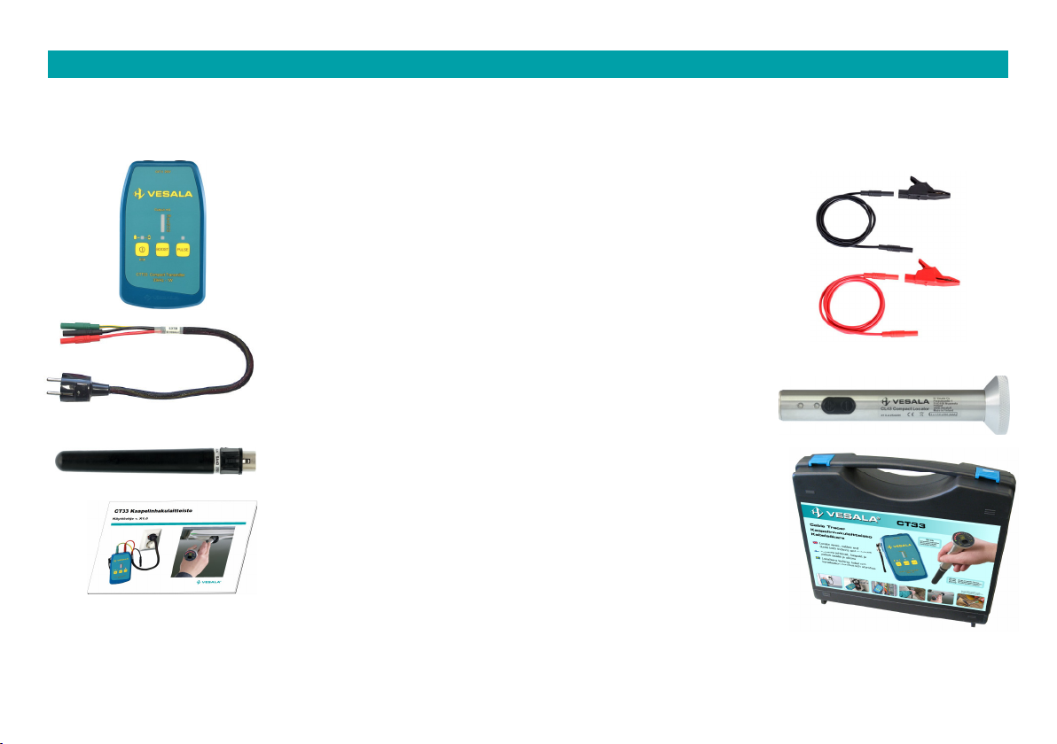
2.1 CT33 Basic setup
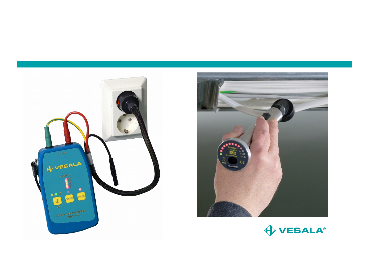
CTT33 transmitter for galvanic signal feeding.
Transmitted frequency 33kHz.
TB10m and TB10p CAT-III –feeding cord (black and
red, 1.0m, 4mm safety banana plugs).
XKKp and XKKm safety crocodile clip (black and red).
S3TB feeding cord, 0.5m Schuko/ 3 pcs. safety banana
plugs.
CL43 Receiver for tracing the signal of the transmitter.
SA43 Rod probe to trace cables and sondes on 10kHz
and 33kHz frequency.
KOCT33 User manual
KLCT33 Carrying bag for the equipment, accessories
and other installation tools (Polypropylene, ~400 x 350
x 90 mm).
CT33 User Manual v. X1.0 4
Page 6

2.2 Transmitter accessories
PM50 (Ø 50mm) or PM100 (Ø 100mm): Clamp-on
transformers for signal feeding when direct galvanic
connection to cable is not possible.
10/TX-Earthstake
SPA10 Pipe transmitter antenna for tracing of small
pipes and ducts (length 10 m).
2.3 Receiver accessories
SA05 Rod probe to locate 512Hz sondes.
LA43 Close range probe to trace and identify cables
and wires from a short distance on 10kHz and 33kHz
frequency.
KA43 Capasitive probe for wire pairs identification.
A selection of duct sondes and push rods are
available as accessory to locate ducts and pipes and
their blockages.
CT33 User Manual v. X1.0 5
Page 7
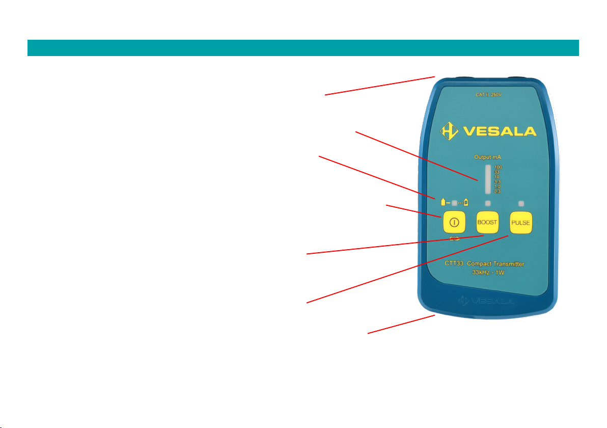
3. CTT33 User interface
Output connectors:
4 mm safety banana jacks for tracing signal output.
Output mA:
LED bar: Output current display (also software version and
battery status)
Power LED
If power LED blink, batteries are weak.
Power button:
To turn power on and off. While powering on LED bar briefly
displays software version and after that it displays battery status
with reference to full batteries. When device is on, also a short
press will display battery status similarly.
BOOST:
Output power selection: When BOOST LED is on,
higher output power is selected.
PULSE:
Output signal mode selection: Signal can be
continuous (default) or slowly pulsed or fast
pulsed. PULSE LED displays which mode is on.
Battery compartment (on the backside of the enclosure. Lid has screws).
CTT33 uses 6 1.5V LR6 (AA) alkaline batteries. Similar NiZn or NiMH batteries can
be used but they require a separate charger.
CT33 User Manual v. X1.0 6
Page 8
4. Basics on how to use the transmitter
CTT33 transmits 33kHz (32,768Hz) signal always when it is on. The default output power is sufficient for most needs.
If BOOST mode is selected (BOOS LED on) output signal is higher but batteries are also drained faster.
When PULSE LED is on continuously, output signal is continuous. Press PULSE button once or twice to choose 4Hz or
8Hz pulsed signal correspondingly. With receiver pulsed signal is often easier to distinguish from noises. Two pulsed
signal modes enable using the two transmitter method for locating wire cuts.
Feeding cords are used to connect the transmitter to the target. Standard cords are safe when properly used but
safety precaution must be followed all the time when working with live wires. If galvanic connection and feeding is not
possible, inductive signal feeding with a clamp-on transformer may be used instead.
Warnings concerning the transmitter
When operating with mains targets, always use contact proof and right safety class cords and
adapters, and follow safety instructions.
CTT33 transmitter may be connected to max. 230V rms voltage!
If either transmitter output terminal is connected to a live target, dangerous voltage or current
may appear on wires connected to the other output, unless they are properly grounded.
Avoiding interference with telecommunication or electric network is always the responsibility of
the user.
Risk of electric shock: Always disconnect feeding cords before opening the battery lid or
enclosure.
CT33 User Manual v. X1.0 7
Page 9
Indicates received signal
ength; the higher pitch and
If necessary repeat 1 to 3 to get the right frequency. Connected
be allows choosing only frequencies supported by the probe.
In
normal operation arc displays
received signal strength with
512/10k/33k
LEDs display the active
operating frequency when the
frequency is changed or when
a probe is connected to the
power
Choose
probe according to
Press here
to remove
Batteries are
located under the user
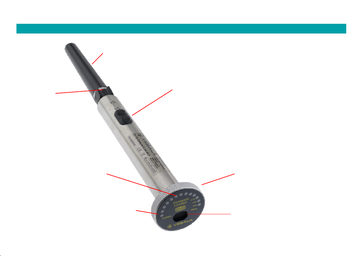
5. CL43 Receiver user interface
Probe
release
button:
the probe.
Arc of 12 red LEDs:
24 levels. The
CL43 device while power on.
Power LED: Green LED indicates
on. LED blinks if battery is weak.
Probe:
the tracing task.
CT33 User Manual v. X1.0 8
(+) and (-) buttons:
(+) long press: power on / off
(+) extended pressing during start-up: makes the LED arc show
firmware version.
(+) releasing press during start-up: makes the LED arc briefly
display battery status and the active operating frequency with one
of the three rightmost LEDs.
(+) and (-) short presses: gain setting up or down, 5 or 7 steps
available depending on connected probe. A beep sound indicates
change of gain, no beep means that maximum or minimum has
been reached.
(-) long press: Initiate change of receiving frequency mode:
1) Press (-) until a beep is heard. Keep it pressed!
2) Press (+) until another beep is heard.
3) See the LED arc: One of the 512/10k/33k LEDs briefly
indicate chosen frequency.
pro
SA05 probe always forces CL43 to 512Hz mode.
Batteries:
interface cap.
Speaker:
str
volume, the stronger the signal.
Page 10

6. Putting the CL43 receiver into use
Batteries:
CL43 receiver uses 3pcs AAA (IEC LR03) alkaline batteries. Compatible
NiZn batteries can be used but they must be recharged in a separate
charger.
To change batteries, turn the user interface cap (1) off and pull the
battery holder (2) out from the tube. Replace old cells with new ones.
Observe battery polarity: (-) poles must be placed against the spring
contacts. Insert the battery holder back into CL43 tube according to the
arrow symbol (3). Turn the user interface cap back on the tube (4).
Connecting /disconnecting probes:
CL43 always requires a probe to operate. To attach a probe, push the
probe connector (1) in to CL43 socket (2) aligned as in the image until
the locking clicks. To remove a probe: Press the release button (3) under
the rubber to release the locking and pull the probe out.
3
1
Warnings concerning the receiver
Though it is not possible to get an electric shock via CL43 receiver probes at less than 600V
environment, it is NOT suggested to use CL43 probes so that they touch live targets.
Do not ever let CL43 body touch live targets.
When operating with mains targets, always follow safety instructions.
124 3
2
CT33 User Manual v. X1.0 9
Page 11

7. Using the receiver and probes
7.1 Choosing right frequency and probe for each task
CL43 receiver supports 512Hz, 10kHz and 33kHz frequencies so it is suitable for various tracing tasks:
Frequency Probe Intended use Operating distance
33kHz SA43 Cable & wire tracing with the CTT33 transmitter
Locating 33kHz duct sondes (Vesala MPL4-33, MPL6-33, MPL7-33, MPL9-33, PL18-33)
33kHz LA43 Cable & wire tracing and identification at close range with the CTT33 transmitter ≤ 30cm
33kHz KA43 Wire tracing and identification with the CTT33 transmitter ≤ 20cm
10kHz SA43 Cable & wire tracing with some of Vesala 10kHz transmitters
Locating 10kHz duct sondes (Vesala MPL6-10, MPL7-10, MPL9-10, PL18-10)
10kHz LA43 Cable & wire tracing and identification at close range with Vesala 10kHz transmitters ≤ 30cm
10kHz KA43 Wire tracing and identification with Vesala 10kHz transmitters ≤ 10cm
512Hz SA05 Locating 512Hz duct sondes (Vesala PL18-05, PL42-05) ≤ 13 m
With CTT33 transmitter always use 33kHz receiving frequency with CL43 receiver and either black SA43 rod probe,
black LA43 close range probe or red KA43 probe. Green SA05 rod probe is only for locating 512Hz duct sondes.
7.2 Setting receiver gain
To adjust CL43 receiving sensitivity, or gain, press (+) or (-) buttons briefly. Depending on the attached probe, there
are 5 or 7 gain steps available. A beep sound indicates change of gain, no beep means that maximum or minimum
has been reached. It is recommendable to use gain which makes the LED arc length to be approx. in the middle; that
way changes in signal strength are easiest to notice. Audio signal volume and tone pitch from the speaker follow the
received signal strength.
30cm ... 10m
≤ 10m
30cm ... 10m
≤ 5 m
CT33 User Manual v. X1.0 10
Page 12
8. How to use a cable tracer
This chapter demonstrates principles on how to use the CTT33 transmitter and CL43 receiver. They are repeatedly
faced in practical situations so it is essential to understand them. Operating principles usually don’t depend on cable
type (whether telecom, mains etc.), instead cable connections play the major role.
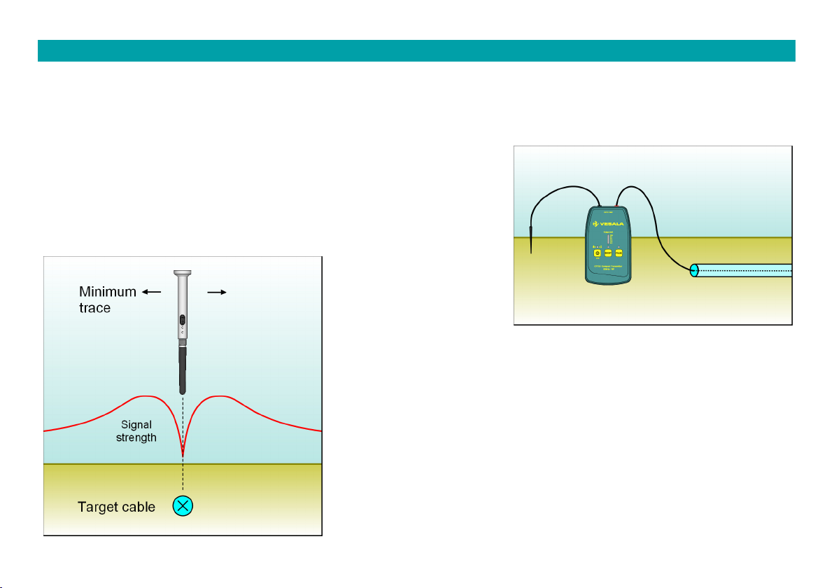
8.1 Locating cables from a distance
Transmitter: Connect one transmitter output to the cable. To make
sure that the tracing signal current return path is distributed widely
to the surrounding soil, use a ground pick or additional wire for the
other output. Only on special occasions both transmitter outputs are
connected to the wires of the traced cable.
Receiver: Follow the cable's route using the SA43 rod probe. Rod
probe is very directive, so between two strong signals a very narrow
and signal minimum can be seen exactly in the direction of the
traced cable (see the image). Hence this is called the minimum (or
null) trace method.
CT33 User Manual v. X1.0 11
Page 13

It is also possible to determine cable depth with CL43 and SA43:
Tilt the SA43 probe to a 45 degree angle and find a second
minimum. Distance between the first minimum A and the second
minimum B equals to cable depth.
8.2 Tracing indoor cables
Transmitter: Connect one transmitter output to one or more of the
cable’s wires and second output to a grounding e.g. to wall socket
PE (earthing) connector.
CT33 User Manual v. X1.0 12
Page 14

Receiver: Scan wall surface with the LA43 probe to track a
signal minimum between two strong signals. If the cable is
further away than 30cm, use SA43 probe instead.
Due to common groundings, signal may also be heard from
nearby cables but weaker than from the right cable.
Transmitter: Alternatively connect both transmitter outputs
to two different wires of the cable, such as wall socket N and
PE. This feeding is more reliable as there is usually less cross
talk to other cables hence making it easier to identify the
right cable from others.
Receiver: With the above feeding, tracing distance is less
than 20cm. Scan wall surface with the LA43 probe to track a
signal maximums and minimum. As conductors are often
twisted inside the cable, signal strength appears to go up and
down or minimum zigzags from side to side.
CT33 User Manual v. X1.0 13
Page 15

8.3 Identifying wires and wire pairs
Transmitter: Connect both transmitter outputs to the wire
pair that needs to be traced or identified.
Receiver: Use KA43 probe and scan as close as possible over
terminal modules to find signal maximum. Strongest signal is
above the right pair. Due to cross talk, signal can be heard
elsewhere too but weaker.
When the right pair has been found, between its wires there
is a minimum. This requires that probe is placed very close to
the wires or the pair has open ends.
KA43 probe can be used to identify pairs also along their
path, such as on shelves or bunches.
CT33 User Manual v. X1.0 14
Page 16

9. Locating underground cables
9.1 Neutral electric cables and telecom cables
Task: The route of a neutral electric cable or telecom cable must be traced above ground.
- CTT33: Connect one transmitter output to one or more
wires of the cable. Same wire(s) should preferably be
grounded at the other end. Connect transmitter second
output to a grounding, preferably with a ground pick to
damp soil.
- CL43: Use SA43 probe. Trace the cable route by pointing
the probe to the signal minimum A.
- Define cable depth by turning the receiver to 45° angle.
Trace right above ground until a second minimum B is
found. Cable depth H equals to the distance A-B.
CT33 User Manual v. X1.0 15
Page 17

9.2 Live mains cables
Task: The route of a live electric cable must be traced above ground.
- CTT33: Connect one transmitter output to the protective earth, e.g. to a wall socket PE contact. To trace
the feeder cable of a metallic light pole, connect transmitter output to the earthed pole itself. Connect
transmitter second output with a ground pick to soil as far as possible.
- CL43: Use SA43 probe. Trace the cable route by pointing
the probe to the signal minimum. If necessary, define
cable depth as described in the previous paragraph.
CT33 User Manual v. X1.0 16
Page 18

9.3 Cables that can’t be reached for galvanic feeding
Task: The route of a live or neutral cable must be traced above ground but cable ends can’t be
reached.
- CTT33: Connect transmitter to a clamp-on transformer and place the clamp around the cable in a place
where the cable is visible. Note: Using a clamp requires that the cable has been grounded at the near end,
preferably at both ends.
- CL43: Use SA43 probe. Trace the cable route by pointing the probe to the signal minimum. If necessary,
define cable depth as described in the previous paragraphs.
CT33 User Manual v. X1.0 17
Page 19

10 Tracing cables and wires indoors
10.1 Live and neutral electric cables
To connect transmitter to live targets, always use proper
contact proof safety class cords and adapters and follow
safety instructions.
WARNING! If either transmitter output terminal is
connected to a live target as shown in the figure, a
voltage appears on wires connected to the other
output as well, unless they are properly grounded.
Task: The route of a live or neutral cable must be
traced from a short distance, e.g. inside walls or on
cable shelves.
- CTT33: Connect transmitter between the wall socket N
and PE contacts (not to L contact) with the S3TB cord. This
method applies to situations where cable is disconnected
or a fuse has blown.
CT33 User Manual v. X1.0 18
Page 20

CL43: Use LA43 probe. Trace the cable route by following
the signal maximum. Right above the cable there is often
a signal minimum.
Task: The route of a live or neutral cable must be
traced e.g. on a cable shelf.
- CTT33: Connect one transmitter output between a neutral wire of the cable and a separate grounding. Use
a ground pick if necessary.
- CL43: Use SA43 probe. Trace the cable route by pointing the probe to the signal minimum. At a distance
less than 0.5m LA43 probe can be used too.
- If cable’s wires are disconnected, signal gets weaker along the path and LA43 probe works better. Closer to
the end, signal minimum gradually disappears and there is only a signal maximum above the right cable.
CT33 User Manual v. X1.0 19
Page 21

10.2 Wall sockets and circuit breakers & fuses
Task: Electronic circuit breaker for a certain live wall socket needs to be located at the electrical
panel or cabinet.
CTT33: Use the S3TB cord and connect transmitter
between the wall socket's L and N or L and PE contacts.
CL43: Use LA43 probe. Scan and track all circuit breakers
at the electrical panel which give a strong signal. It is
normal that several circuit breakers give a signal as they
are parallel connected via their phase rail.
Above the right circuit breaker there is usually a very
strong signal and a minimum in the middle. If possible
turn the circuit breaker off: Signal level should decrease
significantly.
It is recommendable to practise receiver use beforehand
with known fuses/breakers.
NOTE! If there are several wall sockets connected to
the same circuit breaker, transmitter current
spreads to other directions and makes it more
difficult to locate the right circuit breaker.
CT33 User Manual v. X1.0 20
Page 22

10.3 Cables that can’t be reached for galvanic feeding
Task: The route and end of a cable from a cabinet needs to be located without disconnecting the
cable or opening the cabinet.
- CTT33: Connect transmitter to a clamp-on transformer
and place the clamp around the cable in a place where the
cable is visible. Note: Using a clamp requires that the
cable has been grounded at least at the near end.
- CL43: Use LA43 probe. Trace the cable route inside a wall
or on cable shelf by following the signal minimum.
- If the other end of the cable is grounded the whole route
of the cable is traceable and even SA43 probe can be used
by following the signal minimum.
CT33 User Manual v. X1.0 21
Page 23

10.4 Tracing and identifying wire pairs
Task: A wire pair needs to be traced between cross connection terminals and identified at the
other end.
- CTT33: Connect both transmitter outputs to the wire pair
that needs to be traced or identified. Pair can be unused
telecom pair or other unused pair of wires.
- CL43: Use KA43 probe. At cable bunches the right pair
gives the strongest signal when the KA43 tip is close to it.
- If the pair has been connected to a terminal module, scan
KA43 as close as possible over the terminals to find signal
maximum. Due to cross talk, signal can be heard
elsewhere but the strongest signal is above the right pair.
Between the right wires there may be a minimum. Also
open wires can be identified this way.
CT33 User Manual v. X1.0 22
Page 24

11 Tracing cable faults
11.1 Location of a short circuit fault
Task: Cable has a short circuit fault which location
needs to be traced.
- CTT33: Connect transmitter outputs between the shorted
wires of the cable. If the short is to the shielding, connect
transmitter between the shorted wire and the shielding.
- CL43: Use LA43 probe. Monitor signal strength along the
cable surface. At fault spot signal gets stronger and then
quickly disappears. Low-ohmic short-circuit are easier to
find. With shorts caused by water in a cable result depends
on how wet the cable is. Ground leaks and leaks to
shielding are all traced in a similar manner.
CT33 User Manual v. X1.0 23
Page 25

11.2 Location of a open wire (cut fault)
Task: Cable has a open (cut fault) which location needs to be traced.
- CTT33: Connect one transmitter output to the open wire. Connect second output parallel to all remaining
wires and possible shielding and ground them all, preferably using a ground pick to soil.
- CL43: Use LA43 probe. Monitor signal strength along the cable surface. At the fault spot signal quickly
weakens.
CT33 User Manual v. X1.0 24
Page 26

Using two transmitters to locate a cut fault.
- CTT33: Connect both transmitters' one output to the cut/open wire. Connect second outputs parallel to all
remaining wires and possible shielding and ground them all, preferably using a ground pick to soil at both
ends. Set transmitter A to send fast pulsed signal and transmitter B slowly pulsed signal.
- CL43: Use LA43 probe. Monitor signal strength and pulsing along the cable surface. At the fault spot signal
pulsing should change. Note: This method does not always work because of environmental inequalities.
CT33 User Manual v. X1.0 25
Page 27

12 Floor heating cables and their faults
12.1 Preliminary inspection of the target area
As a first step it is always recommendable to perform a systematic inspection at the cable assembly area,
assembly method as well as fault type.
Typical reasons to floor heating faults
- Cable has been damaged during assembly. In time heating current has gradually burned the conductors,
resulting in an open or short-circuit fault. There may be several faults in the same cable.
- There is an air pocket in the concrete, causing cable over heating and eventually an open or short-circuit.
- The floor structure has changed, e.g. fallen down, causing cracks and damage to cable.
- Renovation work such as drilling or moving fixed furniture has resulted in a latent or immediate damage.
When and how the fault appeared
- Did it blow a fuse (short circuit)
- Did the cable just stop heating (cut cable)
- Did a residual current device trip (ground leak)
- Has there been renovation or other changes made recently or some time before
Measuring cable resistances and capacitances
- Make sure that cable wires are not live and disconnect all from the feeding cable.
- Measure resistances and capacitances between all heating cable wires and shield and compare them to
normal values of an intact cable (L-N / L-PE and N-PE)
- In case the heating cable is shorted to concrete reinforcement, it is worth measuring all wires against the
building’s earthing too.
- Resistance values usually reveal the fault type and which wires are affected. Capacitances may help defining
the fault distance from the measuring point.
CT33 User Manual v. X1.0 26
Page 28

12.2 Tracing floor heating cables and their faults
Task: Floor heating cable route needs to be traced e.g. for defining a fault location or for drilling.
- Follow the route of the heating cable from start to end and mark it on the floor. Often the exact route may
reveal faults due to bad assembly or later renovations, such as:
o Cable has been placed under fixed furniture like closets
o Sauna stove or bench screws have been inserted too close to the cable
o Toilet seat screws hit the cable route
- If the fault can’t be determined by following the route only, it is necessary to try to find spots along the
route where the tracing signal level suspiciously changes (see next paragraph):
o In case of a short circuit, signal can be followed to the fault where it gets stronger and then disappears
o In case of an open circuit, signal usually starts to weaken starting from the fault spot
- CTT33: Cut the power and disconnect all cable wires from the feeding cable. Connect transmitter between the
cable’s phase (L) and neutral (N) wires.
- CL43: Use LA43 probe. Follow the cable route by scanning the floor surface. Usually there is a noticeable
minimum but changes in cable depth and cable’s looping back and forth affect how clearly the minimum can
be detected. Mark the route on the floor with chalk or tape.
CT33 User Manual v. X1.0 27
Page 29

- Especially with cables having a cut SA43 probe may work better than LA43.
- CTT33: Connect one transmitter output to the cable's shielding and second output to a good grounding, e.g.
to the feeding cable’s protective earth PE wire.
- CL43: Use SA43 probe. Trace the cable route by pointing the probe to the signal minimum.
CT33 User Manual v. X1.0 28
Page 30

Task: A short circuit in a floor heating cable needs to be traced.
- CTT33: Connect transmitter between the shorted wires of the cable (in the below figure L and N). Leave
the third wire unconnected.
- CL43: Use LA43 probe. At fault spot signal gets stronger and then quickly weakens or disappears.
CT33 User Manual v. X1.0 29
Page 31

Task: An open fault (cut) in a floor heating cable needs to be traced.
- Several factors affect tracing an open in a heating cable, such as what cable type is at hand, is the cable
fully cut or just one wire and what kind of grounding there is to concrete reinforcement. All these require
carefulness while tracing and yet it is possible that exact fault location can’t be determined.
- CTT33: Connect one transmitter output to the cut wire. Connect the second output to the uncut wire & cable
shielding and connect both of them to an auxiliary grounding, preferably using a ground pick. Do not use
electrical wiring's PE!
- CL43: Use LA43 probe. Monitor signal strength along the cable's route. In this case signal is typically weak
and no minimum can be detected. At fault spot the signal gets even weaker.
CT33 User Manual v. X1.0 30
Page 32

13 Tracing tubes and ducts
13.1 Conductive tubes and ducts inside walls or under ground
Task: The route of a metallic tube needs to be traced under ground or inside wall.
- CTT33: Connect one transmitter output to the tube and the second output to a good grounding using a
ground pick, inserted to the soil as far as possible.
- CL43: Use SA43 probe. Trace the tube route by pointing the probe to the signal minimum. If the tube is
inside a wall, also LA43 close range probe can be used.
CT33 User Manual v. X1.0 31
Page 33

13.2 Non-conductive pipes inside walls etc.
- In these cases an accessory SPA10 (length 10m) pipe transmitter antenna is inserted into the traced tube.
Task: A blockage of a non-conductive tube needs to be located inside wall.
- CTT33: Connect both SPA10 terminals to the transmitter. Insert the antenna into the tube until it hits the
blockage.
- CL43: Use SA43 probe. The SPA10's head or blockage is located where there is a longitudinal minimum and
transversal maximum in the signal strength (see closer instructions in the SPA10 manual).
CT33 User Manual v. X1.0 32
Page 34

Task: The route of a non-conductive tube needs to be traced inside a wall.
- CTT33: Connect one transmitter output parallel to both SPA10 terminals and the second output terminal to
a grounding, such as a wall socket protective earth PE contact.
- CL43: Use LA43 probe. Trace the tube's route by following the signal minimum.
CT33 User Manual v. X1.0 33
Page 35

13.3 Using duct sondes to locate duct blockages
Choosing the right sonde and receiver probe:
10kHz or 33kHz sondes and SA43 rod are optimal to use with non-conductive ducts. 512Hz sondes and
SA05 probe are optimal for cast iron or stainless steel ducts, though they can be used with non-conductive
ducts as well. Regardless of sonde size or frequency, all sondes are traced similarly. It is advisable to
continuously follow the sonde signal as it travels in the duct.
Task: Duct route or possible blockage needs to be
located above ground or inside a wall.
- Approximate location: Hold the CL43 in 45° angle. Scan
left and right with the probe and move to the direction
where the signal in average gets stronger. Approximately
1m location accuracy can be achieved by this method.
- Exact longitudinal location: Hold the CL43 vertically and
follow the sonde signal as it progresses in the duct. To
define the exact longitudinal location of the sonde,
pinpoint the signal minimum line. It runs transversely (in
90° angle) against the direction of the duct & sonde. Mark
the minimum line to ground for a few metres.
CT33 User Manual v. X1.0 34
Page 36

- Exact transversal location: Turn the CL43 & probe to
horizontal position and hold it transversely (in 90° angle)
above the minimum line. Keep the probe in this position
and height and move left and right on the minimum line to
find the strongest signal you can get. Signal peak
pinpoints the exact sonde location under ground.
- Sonde depth: Hold the CL43 & probe horizontally and
transversely (in 90° angle) to the minimum line. Move
probe further ahead to the sonde nose direction until
another minimum is detected. Sonde depth h is the
distance s of the two minimums multiplied by 1.4.
- Special case: How to locate a sonde close to a very
interfering cable, duct or rail: Turn the CL43 & probe
parallel to the interfering source (usually horizontal). Keep
this attitude and move the CL43 & probe ahead to the
sonde nose direction until a signal maximum is detected.
CT33 User Manual v. X1.0 35
Page 37

14. Technical data, maintenance and service
14.1. Technical data
Transmitter CTT33
Output signal 33kHz (32,768Hz), output signal either continuous or 4Hz or 8Hz pulsed
Output level Output level 20Vrms (in Boost mode), max. current 170mArms (in Boost
mode). Max. output power 1.3W.
Output impedance 100ohms @ 33kHz, 18kohms@50Hz
Indicators 6 LED bar for output current, three other LEDs
Batteries 6pcs, 1.5V IEC LR6 alkaline batteries (or corresponding NiZn or NiMH
cells). Max battery voltage 11V. Low battery warning approx. 6.5V
Power consumption 11 ... 225mA
Rated voltage 250Vrms
Output connectors 2pcs. 4mm safety banana sockets
Output fuse 400 mA, time-delay, 250 V
Over voltage class CAT II 250V
Enclosure ABS, size 155 x 90 x 50mm
Weight Approx. 460g (with batteries)
Enclosure protection rating IEC 60529 IP55
Usage conditions -20...+40C, dry or damp conditions
Storage conditions -40...+60C, dry conditions
CT33 User Manual v. X1.0 36
Page 38

Receiver CL43
Receiving frequencies 512Hz, 10kHz and 33kHz (32,768kHz)
Adjustments 2 buttons: power on/off, 7-step gain adjustment, receiving frequency
setting
Connectors Male XLR for probes
Indicators Green LED (power and low bat warning), 12-level LED arc display for
receiving signal strength, software version and indicating receiving
frequency setting
Audio indicators Internal speaker for trace signal and indication tones
Batteries 3 pcs 1,5V IEC LR03 (AAA) alkaline batteries (or corresponding NiZn
cells). Low battery warning at approx. 3.7V
Power consumption 20 ... 50mA
Enclosure Stainless steel and aluminium, 180mm x Ø40 mm, weight approx. 230g
(including batteries, no probes
Enclosure protection rating IEC 60529 IP44
Usage conditions -40...+60C, dry or damp conditions
Storage conditions -40...+60C, dry conditions
CT33 User Manual v. X1.0 37
Page 39

14.2. Maintenance, storage and warranty
The CTT33 transmitter and CL43 receiver of the CT33 cable tracer equipment do not have any parts that
require maintenance by the user, excluding changing of batteries and connecting cords. To avoid dirt or water
getting in the devices, clean and dry a soiled device carefully before detaching probes or opening battery
compartment. Use a damp cloth, do not use cleaning solvents. If water gets into the battery compartment,
allow device dry at room temperature. We recommend that the equipment is stored under dry conditions and at
room temperature.
H.Vesala Oy (Ltd.) shall not accept liability of any financial losses or damages, nor for any damage incurred to
people, the environment, telecommunications traffic or similar as a result of the use of or the failure to use the
device. CT33 has a one-year warranty against factory defects. Warranty shall not cover batteries or faults
resulting from normal wear and tear or misuse. Users are advised to contact the manufacturer in case of faults
or queries relating to the use of the device. The product has been designed and manufactured in Finland.
VESALA® is a registered trademark of H.Vesala Oy (Ltd.).
CT33 User Manual v. X1.0 38
Page 40

Manufacture, sales and maintenance
Peräsimentie 1, 03100 Nummela, FINLAND
Tel. +358 44 200 2005
Email: info@vesala.fi
Internet: www.vesala.fi
We reserve the right to make changes.
© H.VESALA Ltd. 1914
CT33 User Manual v. X1.0 39
 Loading...