

Page 1
This is the property of Overview Limited, no copying without
permission
except as permitted by copyright
law
23 May 2013
1
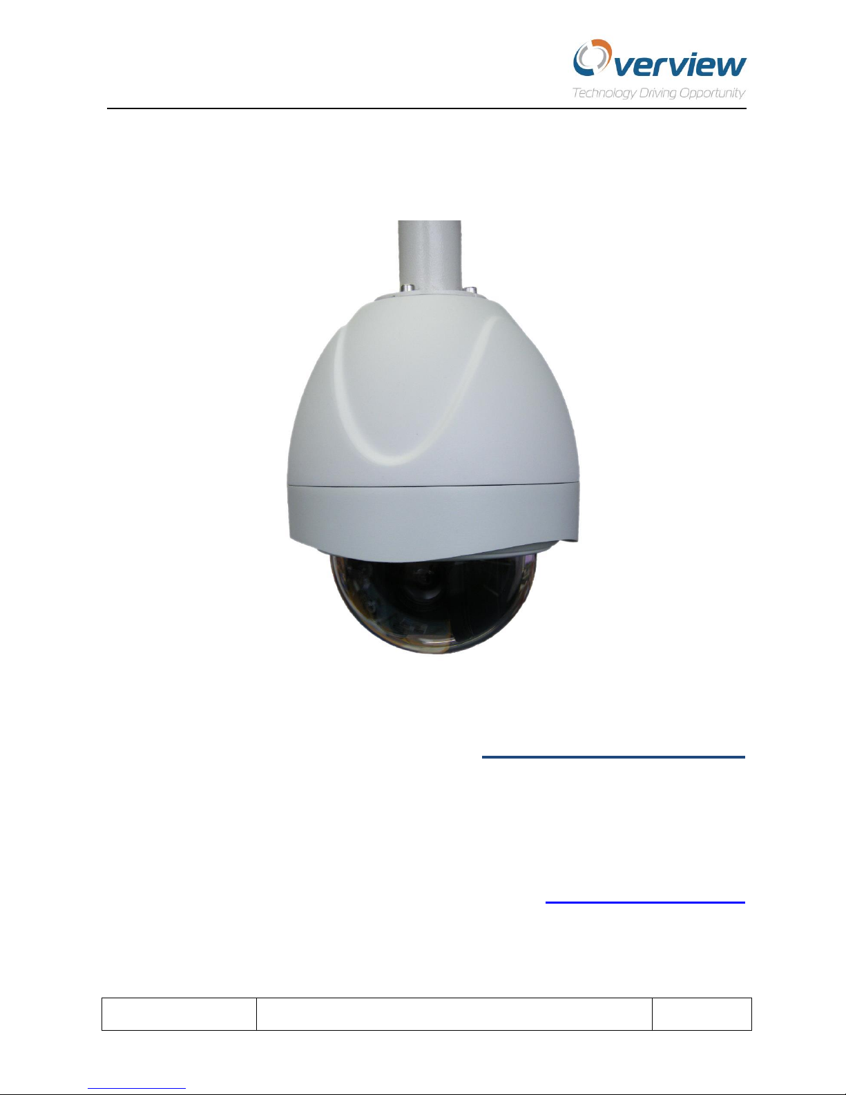
Sparkle Dome
Technical
Manual
Product Number: OVU00106,
OVU00145, OVU00144
Manual Revision: 1.2.3
Software Version: 2.0.0
www.overview.co.uk
Page 2

This is the property of Overview Limited, no copying without
permission
except as permitted by copyright
law
23 May 2013
2
Contents
Introduction.......................................................................................................................................................... 4
Product Features .................................................................................................................................................. 4
Precautions and Warnings.................................................................................................................................... 4
Contents Supplied within the Box ........................................................................................................................ 5
Instructions for the Disposal of Electric and Electronic Equipment ..................................................................... 5
Product Specification............................................................................................................................................ 6
Menu System .................................................................................................................................................... 6
Drive Capabilities .............................................................................................................................................. 6
Video System .................................................................................................................................................... 6
Lens................................................................................................................................................................... 7
Mechanical Features ........................................................................................................................................ 7
Electrical Features ............................................................................................................................................ 7
Environmental Features ................................................................................................................................... 7
Controller Protocols.......................................................................................................................................... 8
Installation / Connection ...................................................................................................................................... 9
Wall Mounting Bracket..................................................................................................................................... 9
External / Internal Pendant Mount Dome.......................................................................................................... 10
Mounting ........................................................................................................................................................ 10
Fitting of the safety cable ........................................................................................................................... 10
Connecting the power cables ..................................................................................................................... 10
Mounting the Dome unit ............................................................................................................................ 11
Address Switch Access.................................................................................................................................... 12
Removal of Internal Mechanism ................................................................................................................ 12
Accessing the Address Switches ................................................................................................................. 13
Electrical Connections ................................................................................................................................ 13
Internal Tile Mount Dome – Mounting .......................................................................................................... 14
Hole Cutting Template................................................................................................................................ 14
Ceiling Mount Disassembly ........................................................................................................................ 14
External Cover Mounting............................................................................................................................ 15
Fitting of Internal Mechanism into External Cover .................................................................................... 15
Address Switch Access.................................................................................................................................... 16
Electrical Connections .................................................................................................................................... 16
Address Switches Settings and Controller Protocols...................................................................................... 17
Page 3

This is the property of Overview Limited, no copying without
permission
except as permitted by copyright
law
23 May 2013
3
Address Switches ........................................................................................................................................ 19
Menu Structure .................................................................................................................................................. 20
Introduction.................................................................................................................................................... 20
Menu Structure – Notes ................................................................................................................................. 20
Menu Control Commands .............................................................................................................................. 21
Run Menu ....................................................................................................................................................... 21
Setup Menu .................................................................................................................................................... 22
Motion Menu.................................................................................................................................................. 22
Motion Menu – Formatting Position .............................................................................................................. 23
Motion Menu – Setting Up a Tour.................................................................................................................. 24
Motion Menu – Setting Up a Mimic Tour....................................................................................................... 25
Video Settings ................................................................................................................................................. 26
Joystick Settings.............................................................................................................................................. 27
Privacy Menu .................................................................................................................................................. 28
Alarms Menu – Alarm Setup........................................................................................................................... 29
Alarms Menu – Alarm Mask Setup ................................................................................................................. 30
Alarms Menu – Alarm Holiday Setup ............................................................................................................. 31
Display Options............................................................................................................................................... 32
Display Options – Editing Default Position Text ............................................................................................. 33
Display Options – Setting Up Date and Time ................................................................................................. 34
Special Settings ............................................................................................................................................... 35
Special Settings – Setting Timeout Time ........................................................................................................ 36
Special Settings – Setting Timeout Action ...................................................................................................... 36
Changing the Password .................................................................................................................................. 37
Warranty Return Procedure ............................................................................................................................... 38
Page 4

This is the property of Overview Limited, no copying without
permission
except as permitted by copyright
law
23 May 2013
4
Introduction
Thank you for choosing the Overview Sparkle fully functional Dome camera. Sparkle is an integrated CCD
camera, optical zoom lens and high-speed pan and tilt system. The unit requires external control
equipment to access all its functions.
Product Features
The Sparkle PTZ Dome is a highly flexible precision camera system with a high resolution, high sensitivity
day/night camera and either 18x, 28x or 36x optical zoom. The Sparkle includes an advanced pan & tilt
mechanism with stepper motors for rapid and precise movement control and enhanced accuracy and
reliability. The aluminium pressure die cast upper housing and impact resistant polycarbonate lower
Dome, are highly durable and resilient to vandalism. Supplied as standard with up-the-coax and
multiprotocol RS-485 telemetry, the Sparkle is compatible with industry standard control equipment
making it ideal for system upgrades, as well as new installations.
Precautions and Warnings
Please study the technical manual thoroughly before installing or using the camera unit.
Do not to drop the camera.
Ensure power is disabled before installing the unit.
Installation of this unit should be carried out by a suitably trained and qualified technician in accordance
with local electrical codes.
To prevent the risk of hazards such as fire or shock do not expose this camera to water.
Do not drop or shake the carton severely.
Do not touch the viewing bubble as this may result in a blurred picture.
Do not install the camera in wet or high humidity areas without adequate protection. Moisture can
corrode the electrical components inside the unit over time.
Do not turn the camera to face strong light, which can cause blooming or smearing of the picture.
Do not install or use the camera in an environment of extreme temperatures. The unit is guaranteed for
use within temperatures of -10°C and 50°C.
Do not disassemble the camera with the power on.
This camera is not suitable for the following environments:
Secured to moving vehicles
Within 100 meters of the coast
Explosive atmospheres
Life critical systems
Chemical atmospheres such as chemical manufacturing plants
Page 5
This is the property of Overview Limited, no copying without
permission
except as permitted by copyright
law
23 May 2013
5
Contents Supplied within the Box
Tile Mount Dome Components Supplied
Pendant Mount Dome Components Supplied
Tile mount Dome unit
Pendant Mount Dome unit
Installation and set-up guide CD
Installation and set-up guide CD
Cavity fixing screws
Cable assembly
Instructions for the Disposal of Electric and Electronic Equipment
The Wheelie Bin symbol on this product or its packaging indicates that the product is
required to be disposed of in an acceptable manner. This is in accordance with the
WEEE Directive 2002/96/EC. For more information regarding the correct disposal of this
unit at the end of its life please contact the company where this unit was purchased
from.
Page 6

This is the property of Overview Limited, no copying without
permission
except as permitted by copyright
law
23 May 2013
6
Product Specification
Menu System
The Sparkle on screen menu system offers a simple, intuitive and powerful interface to the complete set of
Dome features, with password protection for increased security.
Password protection: Built in
Languages supported: English, French, Spanish, German and Italian
Drive Capabilities
Specification Value
Number of presets 32 (user configurable)
Number of pattern tours 4*1min (user configurable)
Number of slow tours 8 (user configurable)
Number of fast tours 8 (user configurable)
Preset accuracy
Pan range
0.05°
360° continuous rotation
Tilt range 0-90°
Pan speed 0.01°/s - 360°/s
Tilt speed 0.01°/s - 200°/s
Preset moves - pan Speed 200°/s
Preset moves - tilt Speed 200°/s
Power fail Last action restoration on power up
Software upgrades Fully upgradable over RS-485 link both prior to and post
installation
Joystick control Variable selectable speed ranges for precision control
Variable speed adjustment with zoom depth
Video System
Specification Value
Privacy zones 24 (8 positions per screen. Solid or mosaic)
Video effects Freeze frame
Video format PAL / NTSC (model dependant)
Scanning system 2:1 interlace
Image sensor ¼” interline transfer CCD
Optical zoom speed 2.1s (wide –telephoto)
Digital zoom speed 1.7s
Iris control Automatic with manual override (16 steps)
Focus Automatic with manual override
White balance Automatic
Gain Automatic
IR filter Automatic
Video output Variable 1Vp-p to 2Vp-p, 75 ohms (8 steps)
Video lift 8 steps
Page 7
This is the property of Overview Limited, no copying without
permission
except as permitted by copyright
law
23 May 2013
7
Specification
Value
Specification
Value
Power supply
Input power
18-28 VAC/DC
10 VA nominal
Min temperature
Max temperature
-10°C
50°C peak, 40°C sustained
Surge protection
Certification
Built in surge protection,
limited lightning
protection
CE
Lens
Camera specific (see table below)
Camera
FCB-EX49EP
FCB-EX985EP
FCB-EX1020P
Lens
18x optical zoom
f=4.1mm (wide) to
73.8mm (tele)
F1.4 to F3.0
28x optical zoom
f=3.5mm (wide) to
98.0mm (tele)
F1.35 to F3.7
36x optical zoom
f=3.4mm (wide) to
122.4mm (tele)
F1.6 to F4.5
Digital zoom
12x (216x with optical
zoom)
12x (336 x with optical
zoom)
12x (432x with optical
zoom)
Viewing angle (H)
48.0° (wide) to 2.8° (tele)
55.8° (wide) to 2.1° (tele)
57.8° (wide) to 1.7° (tele)
Minimum
working distance
35mm (wide) to
800mm (tele)
10mm (wide) to 1500mm
(tele)
320mm (wide) to
1500mm (tele)
Mechanical Features (Pendant Dome)
Specification Value
Environmental IP67
Housing construction Vandal resistant die-cast aluminium
Bubble construction Vandal resistant polycarbonate
Internal mechanism Die-cast aluminium
Housing finish White powder coat RAL9002
Weight 3.2kg
Dimensions 207mm (diameter upper
hemisphere) x 250mm (height)
149.5mm (diameter of lower Dome)
Electrical Features Environmental Features
Page 8

This is the property of Overview Limited, no copying without
permission
except as permitted by copyright
law
23 May 2013
8
Controller Protocols
Protocols Name
RS-485 Overview
BBV 485
Ikegami i-LAN
Ikegami 485
Pelco P
Pelco D
Phillips
Samsung
Kalatel
Sensormatic
Ultrack
VTC Scorpio
CBC C-Dome
Forward Vision MIC1-300
VCL
Vicon
SISS
COHN
Co-axial
Pelco Coaxitron ™
Baxall FSK-STD
BBV UTC
Page 9
This is the property of Overview Limited, no copying without
permission
except as permitted by copyright
law
23 May 2013
9
Installation / Connection
Wall Mounting Bracket
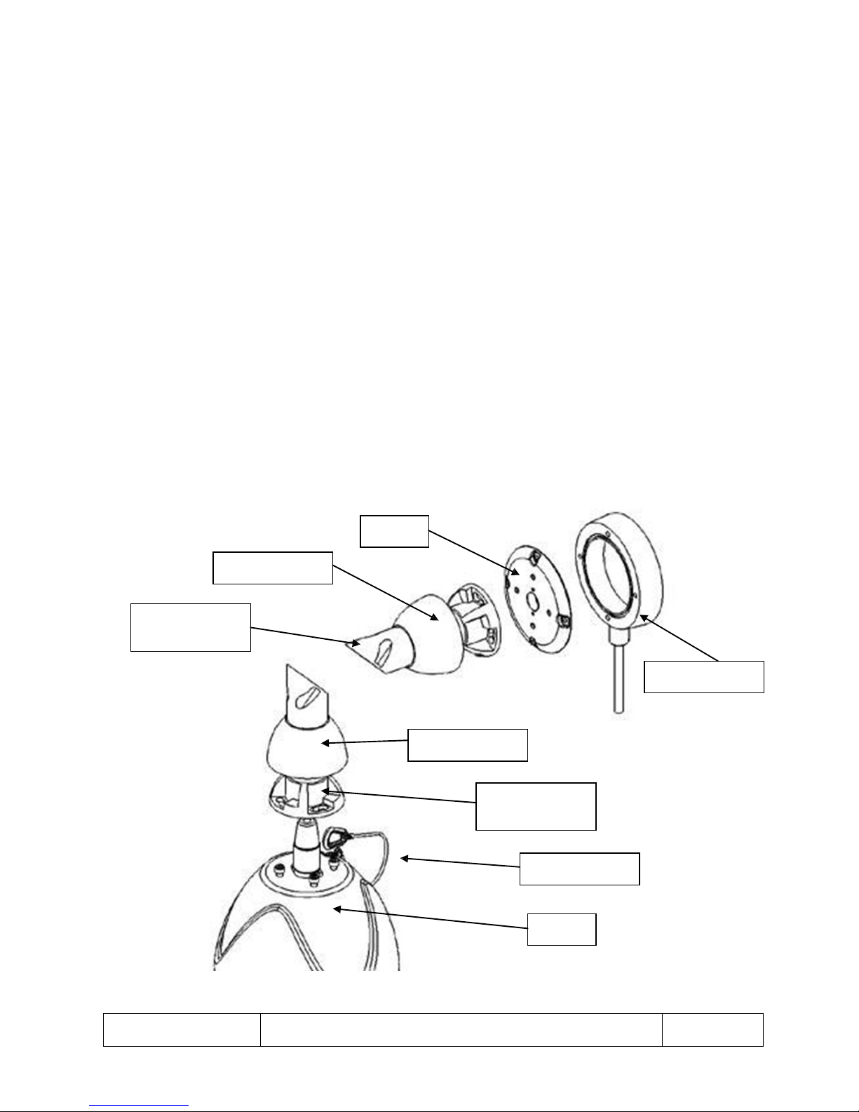
1. Using the base casting as a template, drill and fit wall plugs to the mounting surface. Fit and screw
the base casting to the mounting surface.
2. The cable loom needs to be routed through the various mounting bracket components prior to final
assembly.
3. Screw the cover to the base casting using the 4 x trilobular thread forming screws supplied.
4. Fit the arm A keyholes slots over the M6 screw heads fitted to the cover, and then rotate to lock and
tighten the screws.
5. Slide the plastic cover down the arm, align the two brass pegs in the base casting with the
corresponding holes in the plastic cover and push down.
6. Attach the second arm B to the first arm and fit the two M6 screw and nut sets supplied.
7. Before fitting the Dome, attach the safety cable to the eyelet on the end of arm B. Fit the Dome to
the bracket arm by aligning the keyhole slots with the M6 screw heads fitted to the Dome, rotate to
lock then tighten the screws.
8. Slide the plastic cover down the arm and locate it as in point 5 above.
Cover
Plastic Cover
Arm A (without
eyelet)
Base Casting
Plastic Cover
Arm B (with
eyelet)
Safety Cable
Dome
Fig 1
Page 10
This is the property of Overview Limited, no copying without
permission
except as permitted by copyright
law
23 May 2013
10
External / Internal Pendant Mount Dome
Mounting
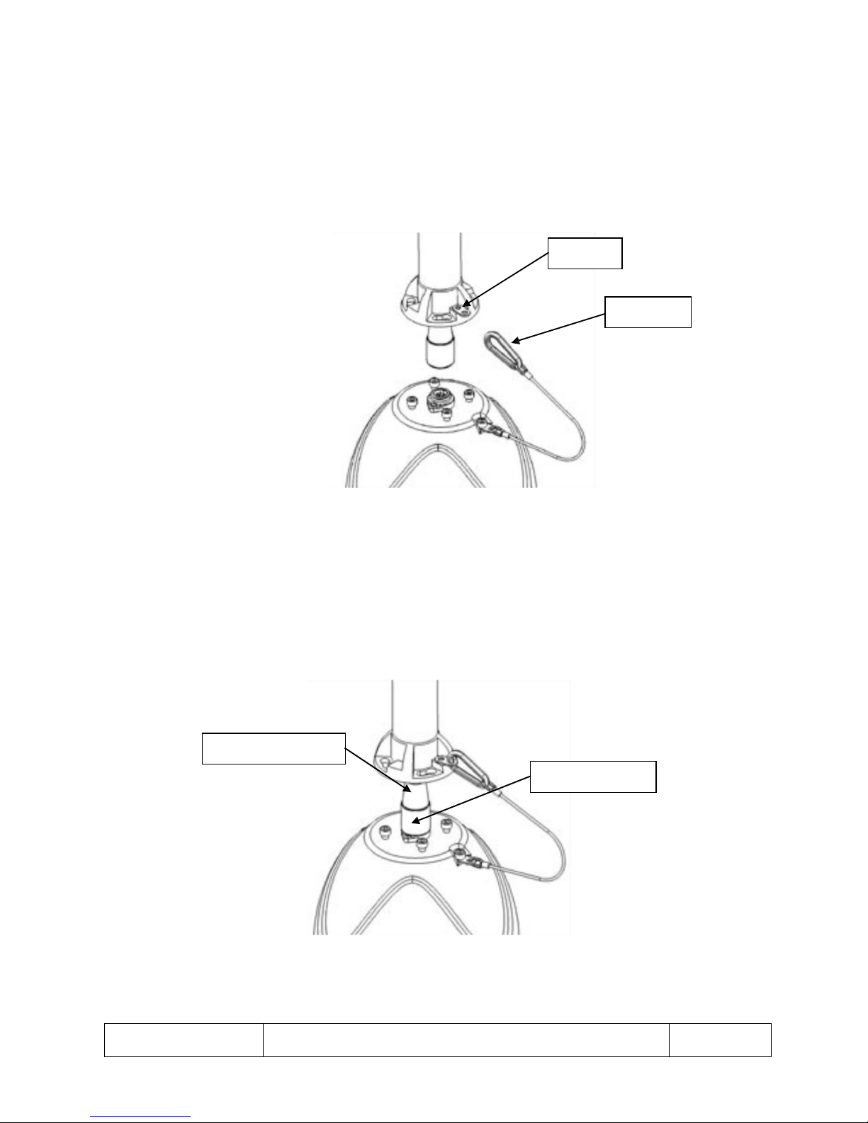
Fitting of the safety cable
1. Lift the plastic cover away from the fixing point on the wall bracket.
2. Clip the caribenna at the end of the safety cable into the eyelet that is fitted to the wall bracket.
Eyelet
Caribenna
Fig 2
Connecting the power cables
1. Connect power cable to the socket on the top of the Dome unit.
2. Screw down the locking ring to secure the power cable.
Power Cable Socket
Locking Ring
Fig 3
Page 11
This is the property of Overview Limited, no copying without
permission
except as permitted by copyright
law
23 May 2013
11
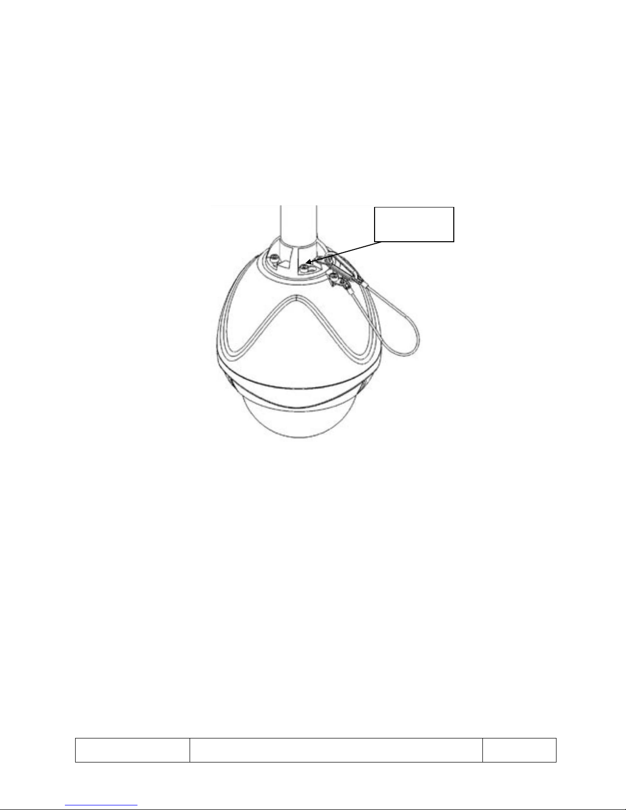
Mounting the Dome unit
1. Make sure the four M6 cap head screws are un-screwed so the heads of the screw are at least 5mm
above the top of the Dome unit.
2. Align the four screws through the holes in the bracket and rotate the Dome so the screws move into
the slots in the bracket.
3. Tighten up the M6 head screws with the socket driver provided.
4. Push the plastic cover back down over the bracket.
M6 Cap Head
Screws
Fig 4
Page 12
This is the property of Overview Limited, no copying without
permission
except as permitted by copyright
law
23 May 2013
12
Address Switch Access
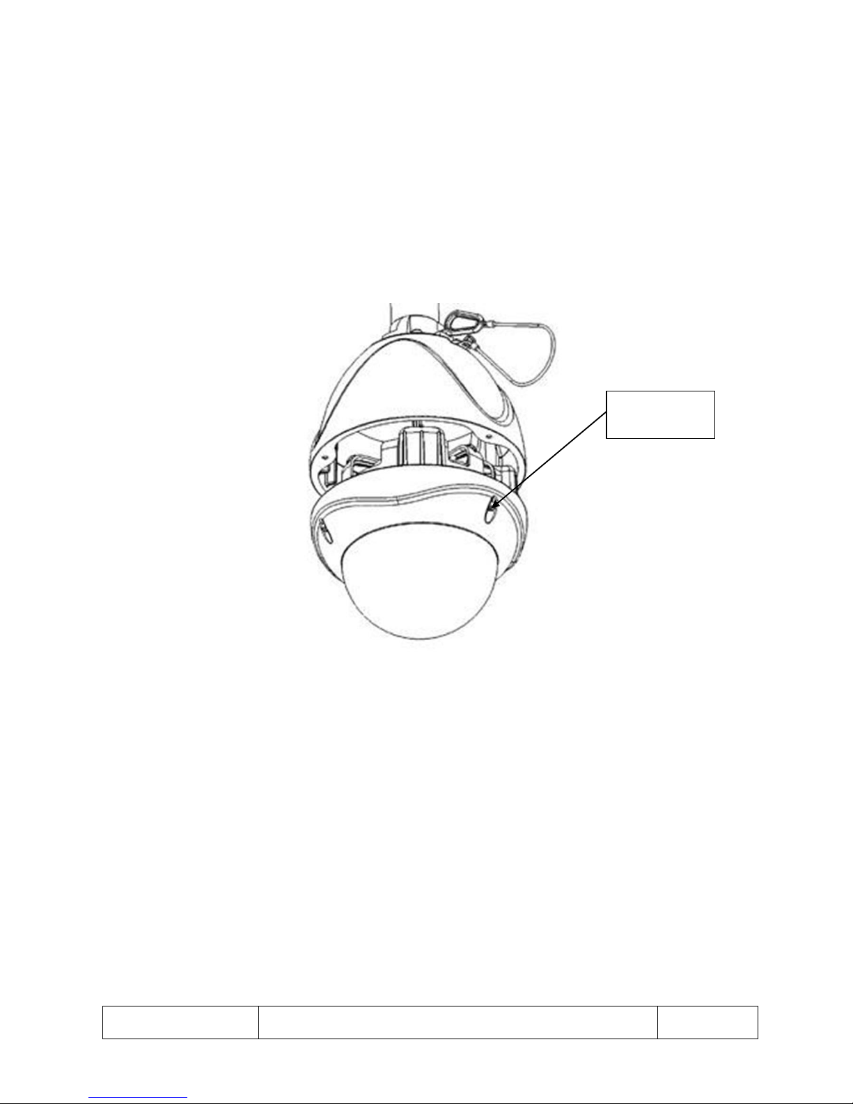
Removal of Internal Mechanism
1. Un-screw the three M5 cap head screws in the lower housing. The screws are captive and will not fall
out of the lower housing.
2. The internal mechanism will drop by approximately 5mm. A safety plate in the upper housing will
hold it there.
3. Rotate the internal mechanism anti-clockwise to free it from the safety plate.
4. The mechanism can now be lowered and the internal power cable can be disconnected from the top
of the internal mechanism.
M5 Cap Head
Screws
Fig 5
Page 13
This is the property of Overview Limited, no copying without
permission
except as permitted by copyright
law
23 May 2013
13
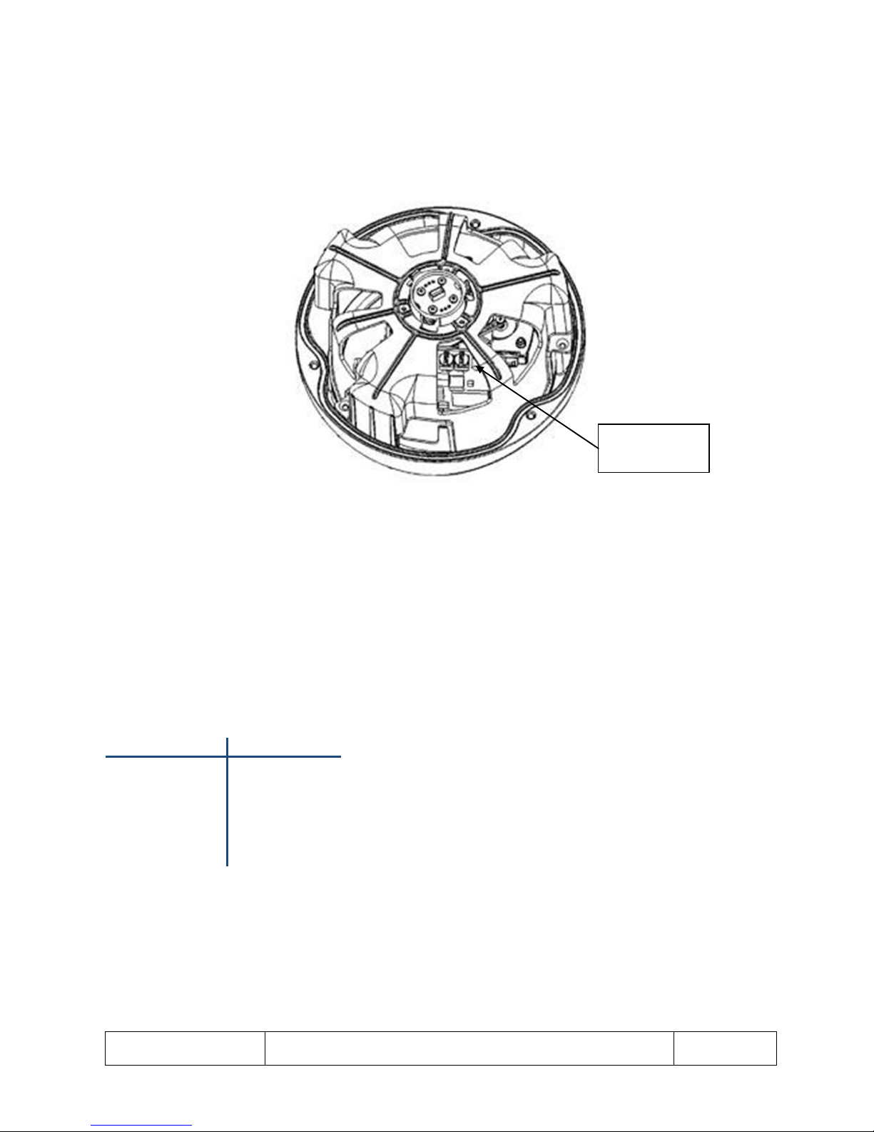
Accessing the Address Switches
1. Rotate the internal drive, making sure not to touch the sensitive PCB, until the two address switches
can be seen through the internal cover.
2. The address switches can now be rotated using a small flat screwdriver to the appropriate settings.
Address
Switches
Fig 6
Electrical Connections
1. The External/Internal Pendant Mount Dome external connections are via an Amphenol connector
with 2 metre composite flying lead comprising of coax, power pair and RS-485 pair.
2. If the lead needs to be extended it should be kept to a minimum and not exceed 25m.
The lead connections are as follows:
Specification Value
Red wire 24V AC live
Blue wire 24V AC Neutral
Yellow wire RS-485 `A’
Green wire RS-485 `B’
Coax screen BNC screen
Coax signal BNC centre pin
Page 14
This is the property of Overview Limited, no copying without
permission
except as permitted by copyright
law
23 May 2013
14
Internal Tile Mount Dome – Mounting
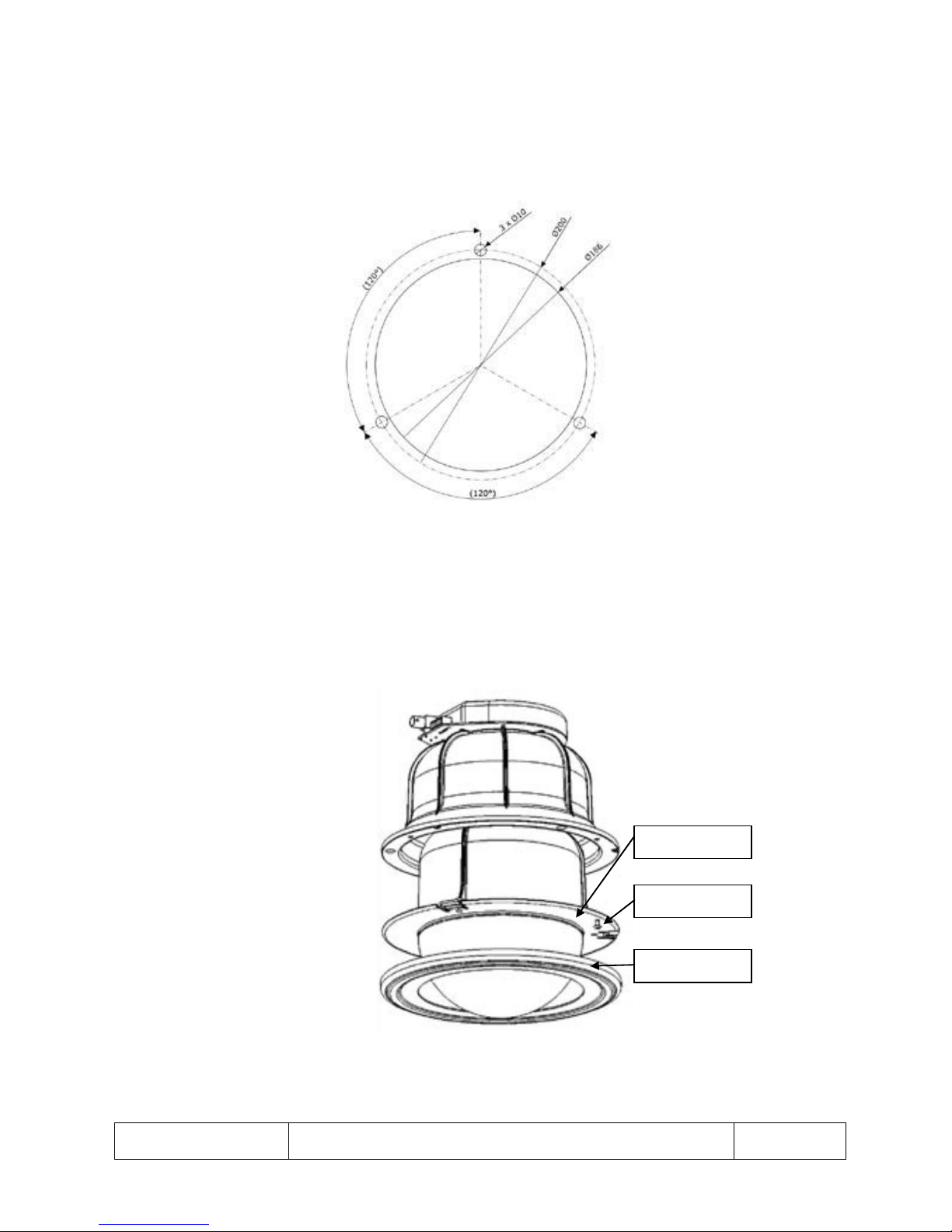
Hole Cutting Template
1. Cut the profile below into the tilt you will be mounting the Dome into.
Fig 7
Ceiling Mount Disassembly
1. Unclip the cover ring from the ceiling mount Dome.
2. Unscrew the locking screw, it is captive in the locking ring and should not completely fall out.
3. Rotate the internal mechanism assembly anti-clockwise and remove it from the external cover.
Locking Ring
Locking Screw
Cover Ring
Fig 8
Page 15
This is the property of Overview Limited, no copying without
permission
except as permitted by copyright
law
23 May 2013
15
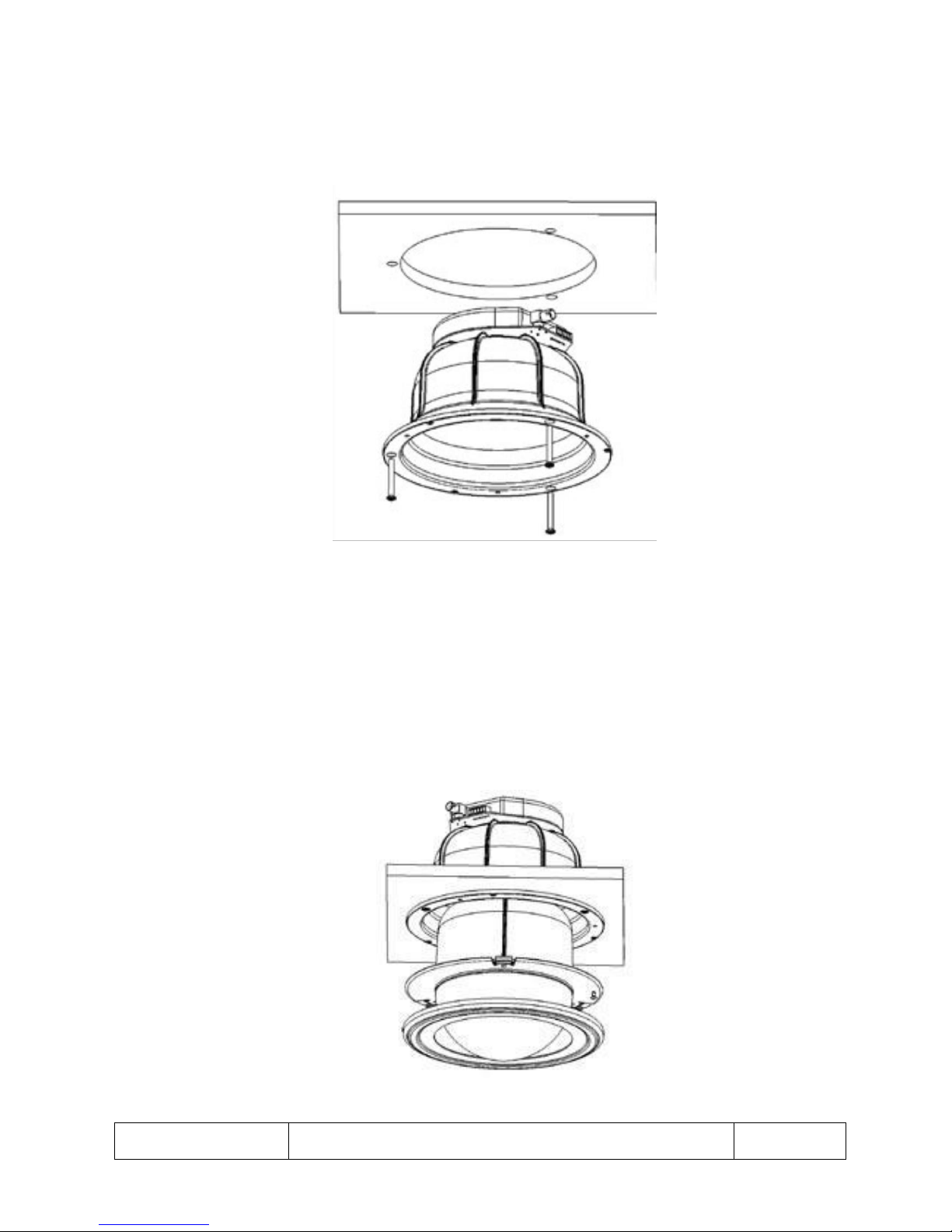
External Cover Mounting
1. Mount the external cover into the pre-cut tile using the M4 cavity screw supplied.
2. Connect the screw terminal block and BNC connector as described in the ceiling mount – electrical
connection (Fig 12) part of this guide.
Fig 9
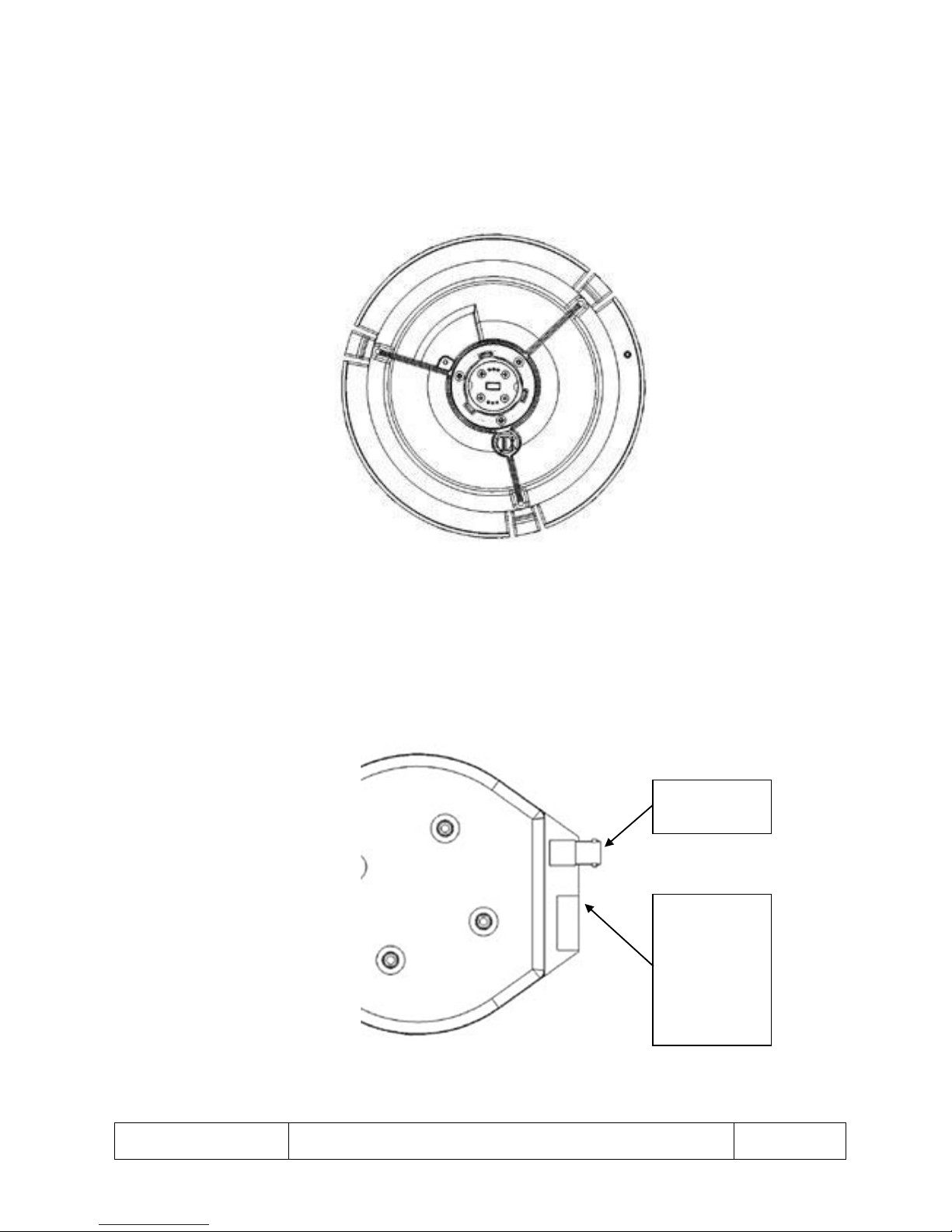
Fitting of Internal Mechanism into External Cover
1. Insert the internal mechanism into the external cover. Rotate clockwise until the mechanism moves
further in, then rotate clockwise further until the mechanism stops turning and the locking ring
clicks.
2. Screw in the locking screw to stop the internal mechanism from being un-screwed.
3. Clip on the cover ring.
Fig 10
Page 16
This is the property of Overview Limited, no copying without
permission
except as permitted by copyright
law
23 May 2013
16
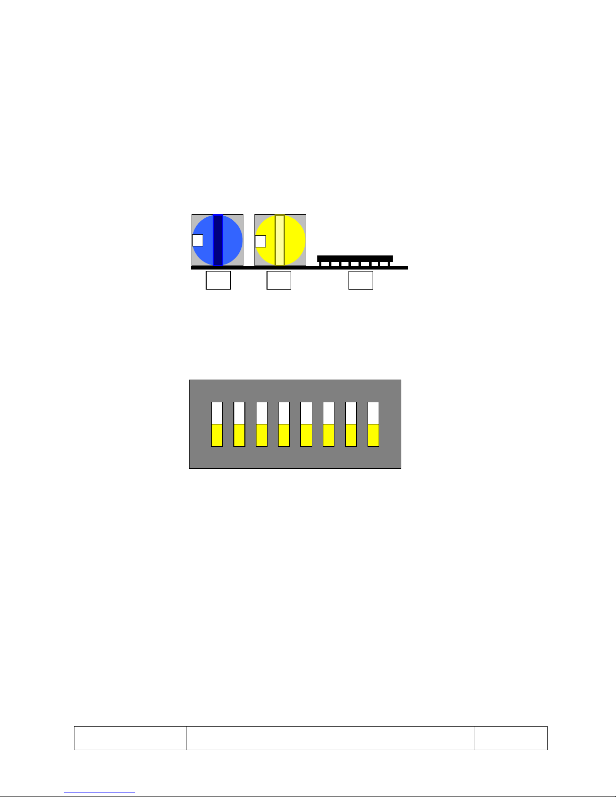
Address Switch Access
1. Remove internal mechanism as shown in section `Ceiling Mount Disassembly’ (Fig 8).
2. Rotate internal drive until you can access the address switches through the hole in the internal
housing.
Fig 11
Electrical Connections
1. Please see below the electrical connections for the ceiling mount Dome.
2. Wire up the screw terminal socket provided according to the pin-out.
Coax Screen
Coax Signal
Earth
Earth
RS-485-“A”
RS-485- “B”
24V AC/DC
24V AC/DC
Fig 12
Page 17
This is the property of Overview Limited, no copying without
permission
except as permitted by copyright
law
23 May 2013
17
Address Switches Settings and Controller Protocols
The address switches are used to set up the controller protocol and the unit ID of each Dome. There are 255
unit ID’s and a maximum of 32 control protocols. The following figures and tables outline how to set up
address switches on a unit.
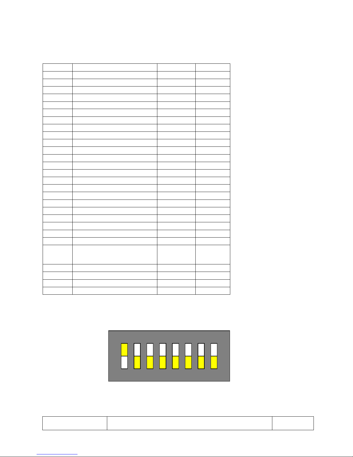
Address switches S1, S2 and S3 (shown in Fig 13) are used to set up the unit ID and the controller protocol. S1
and S2 are hex switches used to set the unit ID and S3 (Fig 14) is used to set up the controller protocol.
S1 S2 S3
Fig 13 Top view of the address switches
ON
1
2
3
Fig 14 Plan view of S3
4 5 6 7 8
Page 18
This is the property of Overview Limited, no copying without
permission
except as permitted by copyright
law
23 May 2013
18
Notes: It must be changed on Dipswitch S3 (nearest base), Bit 1-5 only.
In the table below:
0 - OFF
1 – ON
ID
Dipswitch S3
Baud
Number
Protocol – RS485
bit 5 --- 1
Rate
0 OVERVIEW
00000
9600
1 PELCO_P 9600
00001
9600
2 PELCO_P 4800
00010
4800
3
PHILIPS 960
00011
9600
4
PHILIPS 2400
00100
2400
5 KALATEL_DP
00101
4800
6 SENSORMATIC
00110
4800
7 ULTRAK 00111
9600
8 SAMSUNG_SCC3000
01000
9600
9
VTC_SCORPIO
01001
9600
10
PELCO_D 2400
01010
2400
11 IKEGAMI
01011
9600
12
CBC 01100
9600
13 MIC1_300
01101
9600
14
IKEGAMI_NETWORK_ENCODER
01110
9600
15
SAMSUNG_SCC2000
01111
9600
16 Overview Test Mode
10000
9600
17 VCL 10001
9600
18
BBV 485
10010
9600
19 VICON 10011
9600
20
PELCO_D
10100
9600
21 SISS 10101
9600
22 COHU 10110
9600 (only
1.9.16 &
above)
Protocol - UTC
24 PELCO COAXITRON
11000
30 BAXALL FSK-STD
11110
31 BBV UTC
11111
*See note
Table 1 Controller Protocol Switch Settings
Example: PELCO `P` 9600 = 00001
ON
1
2
3
4 5 6 7 8
Fig 15 Plan view of SW3
*Note: When using the UTC protocol the dome address must be set to 1
Page 19
This is the property of Overview Limited, no copying without
permission
except as permitted by copyright
law
23 May 2013
19
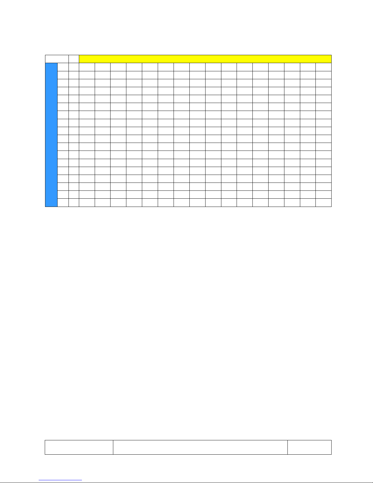
Address Switches
S2 YELLOW
S1
B
L
U
E
0 1 2 3 4 5 6 7 8 9 A B C D E
F
0
0 1 2 3 4 5 6 7 8 9 10 11 12 13 14 15
1
16 17 18 19 20 21 22 23 24 25 26 27 28 29 30 31 2
32 33 34 35 36 37 38 39 40 41 42 43 44 45 46 47
3
48 49 50 51 52 53 54 55 56 57 58 59 60 61 62 63 4
64 65 66 67 68 69 70 71 72 73 74 75 76 77 78 79
5
80 81 82 83 84 85 86 87 88 89 90 91 92 93 94 95
6
96 97 98 99 100 101 102 103 104 105 106 107 108 109 110 111
7
112 113 114 115 116 117 118 119 120 121 122 123 124 125 126 127
8
128 129 130 131 132 133 134 135 136 137 138 139 140 141 142 143 9
144 145 146 147 148 149 150 151 152 153 154 155 156 157 158 159 A
160 161 162 163 164 165 166 167 168 169 170 171 172 173 174 175
B
176 177 178 179 180 181 182 183 184 185 186 187 188 189 190 191
C
192 193 194 195 196 197 198 199 200 201 202 203 204 205 206 207
D
208 209 210 211 212 213 214 215 216 217 218 219 220 221 222 223 E
224 225 226 227 228 229 230 231 232 233 234 235 236 237 238 239 F
240 241 242 243 244 245 246 247 248 249 250 251 252 253 254 255
Table 2 Unit ID Switch Settings
*Note: when using the UTC protocol the dome address must be set to 1 on all domes.
Page 20
This is the property of Overview Limited, no copying without
permission
except as permitted by copyright
law
23 May 2013
20
Menu Structure
Introduction
Sparkle Dome uses a straightforward, simple, intuitive conventional menu structure which features:
Multilingual: the menu can be displayed in English, French, Spanish, German and Italian
Simple intuitive menus
Minimised menu pages and key entry for actions
Alphanumeric password protection
32 preset positions, 8 fast and 8 slow tours, 4 one-minute joystick mimic tours, all of which are easy
to set up from one menu screen
Simple position title insertion
Comprehensive general features
Video gain and lift micro adjust
Real time clock
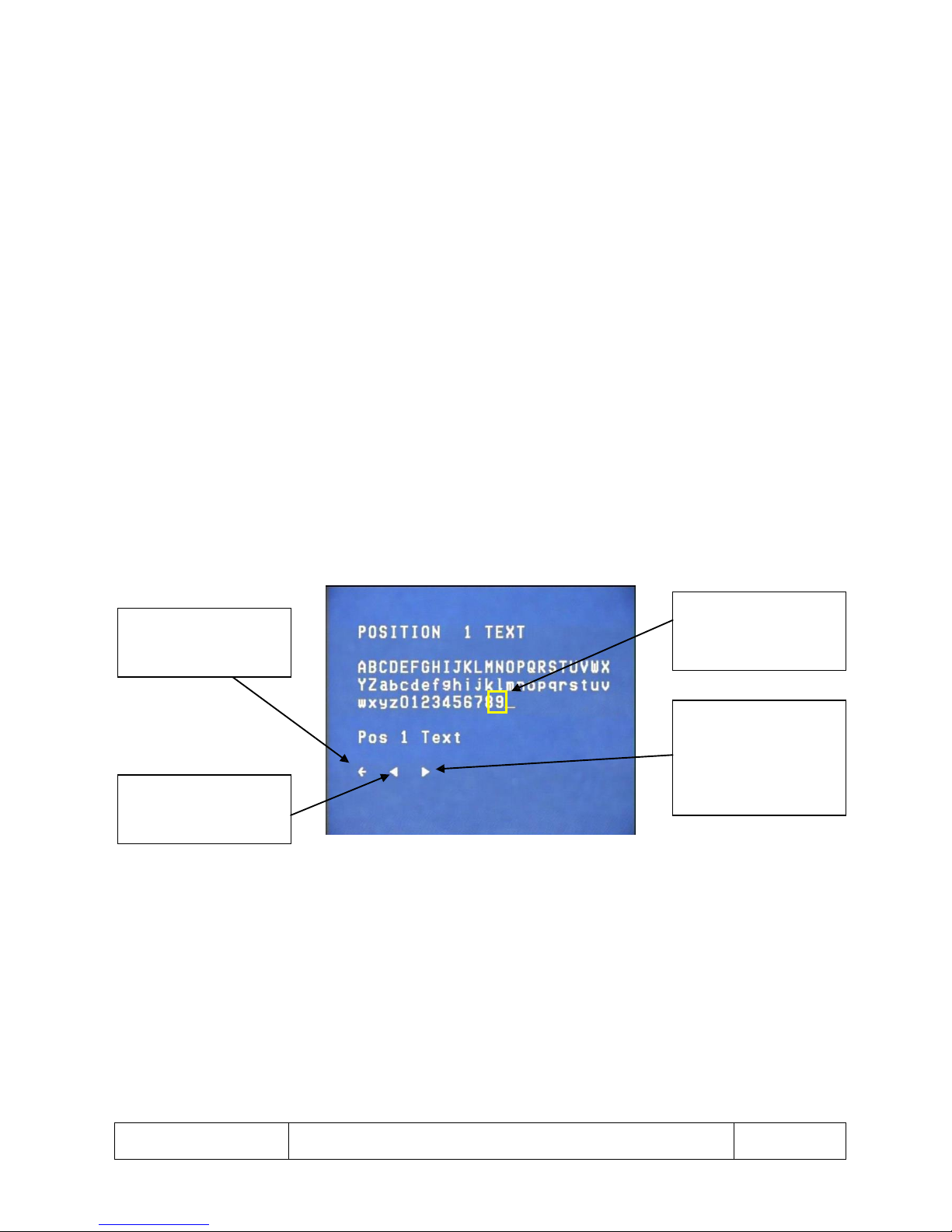
Menu Structure – Notes
Selecting the BACK
arrow
will take the user to
the
previous
screen
In this guide the
light
border indicates the
item
is
flashing
The BACKWARD arrow
deletes the last item
selected by the user
Fig 16
The FORWARD
arrow
confirms the
item
selection, and
returns
the user to
the
appropriate
menu
Page 21
This is the property of Overview Limited, no copying without
permission
except as permitted by copyright
law
23 May 2013
21
Menu Control Commands
GO TO PRESET 95 enters and exits the menus on all protocols with the exception of Kalatel (PRESET 63).
GO TO PRESET 1 acts as select once in the menus. In addition to this, the following, more convenient,
commands also act as enter menu and menu select.
Protocol
Enter/Exit menu
Select in menu
Pelco P 9600
GO TO PRESET 95
IRIS OPEN
Pelco P 4800
GO TO PRESET 95
IRIS OPEN
Kalatel DP
STORE/GO TO PRESET 63
GO TO PRESET 1
Samsung SCC300
OSD
AF
VTC Scorpio
ENTER-in ESC-exit
ENTER
Pelco D 2400
GO TO PRESET 95
IRIS OPEN
Ikegami 485
WIPER
SET
Forward Vision 500
F3
F4
Ikegami I-LAN
WIPER
ONE PUSH
Pelco Coaxitron™
GO TO PRESET 95
IRIS OPEN
BBV400
# +1
1
BBV1000
SHIFT + WASH
PRESET + 1
Table 3 Menu control commands for included control protocols
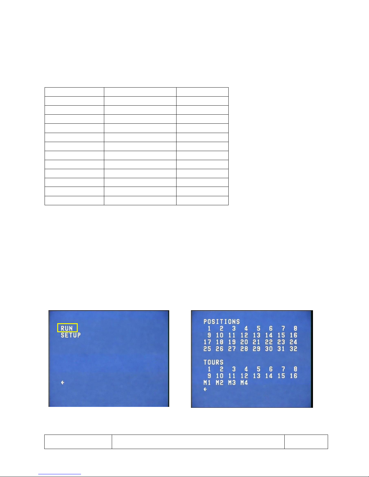
Run Menu
1. Selecting RUN from the START UP screen allows a user to go to a pre-set position or start a tour (See
Fig 17). There are 32 pre-set positions, 8 slow tours (1-8), 8 fast tours (9-16) and 4 one-minute tours
(M) (See Fig 18).
2. When a programmed position or tour is selected the menu will be cleared from the screen and the
unit will execute the appropriate function.
3. If a position or tour is not set, a message will be displayed, POSITION NOT SET or TOUR NOT SET,
respectively.
Fig 17 Start up screen Fig 18 Run menu screen
Page 22
This is the property of Overview Limited, no copying without
permission
except as permitted by copyright
law
23 May 2013
22
Setup Menu
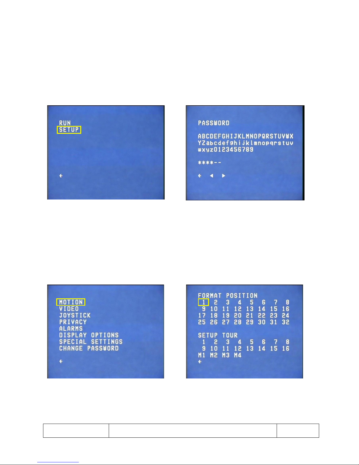
1. The SETUP menu gives the operator full access to set up presents and tours as well as other features
of the unit (See Fig 19). SETUP menu is password protected (See Fig 20).
2. The password is defaulted to “AAAAAA” and can be changed in the CHANGE PASSWORD MENU (See
Fig 69). There is an override password which allows menu access at any time. This is “OVsl07” (Oscar
Victor sierra lima zero seven).
3. If the PASSWORD menu is re-displayed after entering the password instead of the SETUP menu the
incorrect password has been entered.
Fig 19 Start up screen Fig 20 Setup menu Password screen
Motion Menu
1. Selecting MOTION from SETUP menu allows an operator to set up preset positions and tours (See Fig
21).
2. Selecting a position takes the operator to the MOTION menu (See Fig 22).
Fig 21 Setup menu screen Fig 22 Motion menu screen
Page 23
This is the property of Overview Limited, no copying without
permission
except as permitted by copyright
law
23 May 2013
23
Motion Menu – Formatting Position
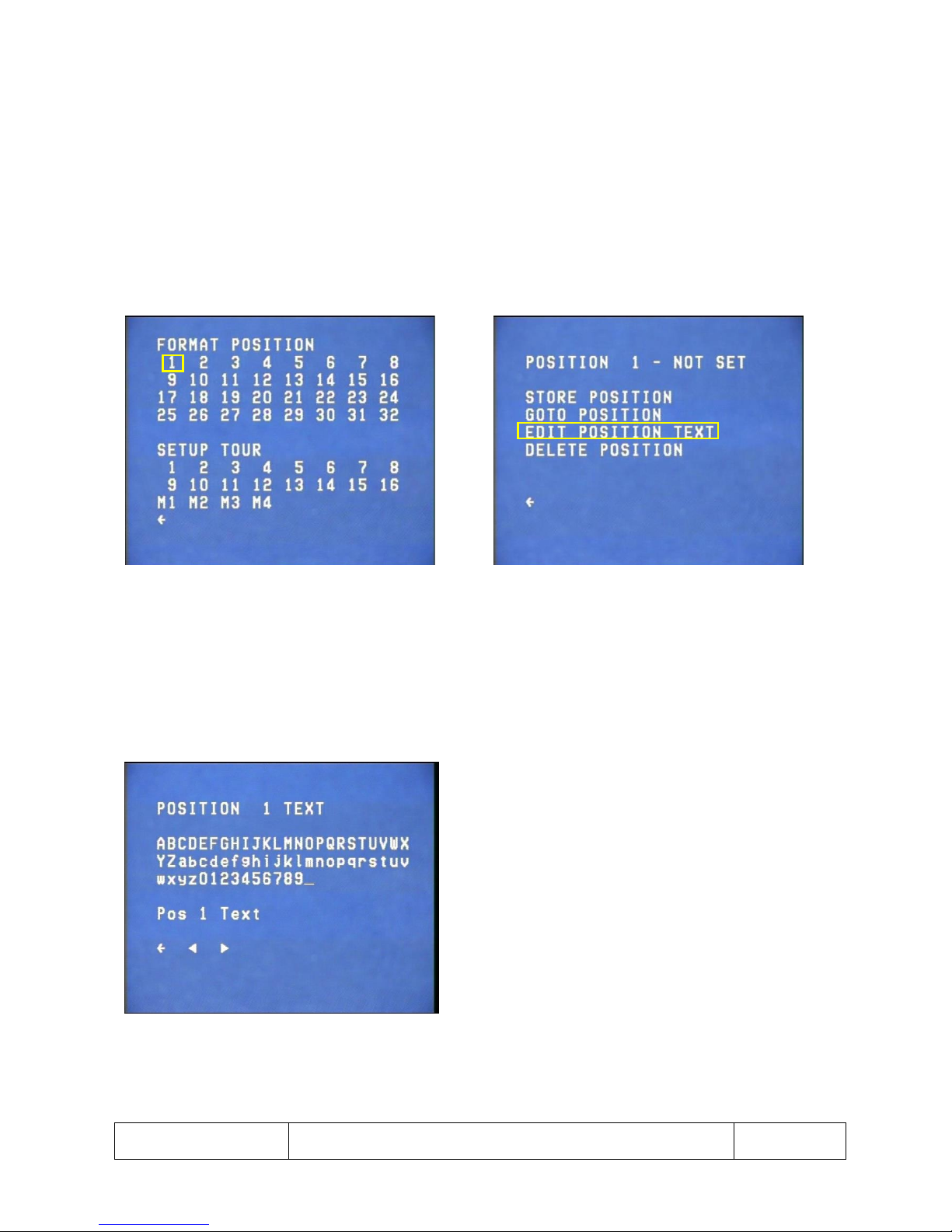
1. Clicking on a position number takes the user to the FORMAT POSITION menu (See Fig 23 & 24).
2. The FORMAT POSITION menu allows the operator to setup a preset position. The top line displays
the position number and its status.
3. STORE POSTION sets the current unit view to the currently selected position number.
4. GOTO POSTION exits the menu and moves the unit to the position.
5. EDIT POSITION TEXT takes the operator to the EDIT POSITION TEXT menu.
6. DELETE POSITION removes the position and resets its status.
Fig 23 Motion menu screen Fig 24 Format Position menu screen
1. In the EDIT POSITION menu custom text can be entered which will be displayed on the screen when
at the position (See Fig 25).
Note: GOTO POSITION, EDIT DEFAULT TEXT and DELETE POSITION will only function if the position has been
set.
Fig 25 Edit Position menu screen
Page 24
This is the property of Overview Limited, no copying without
permission
except as permitted by copyright
law
23 May 2013
24
Motion Menu – Setting Up a Tour
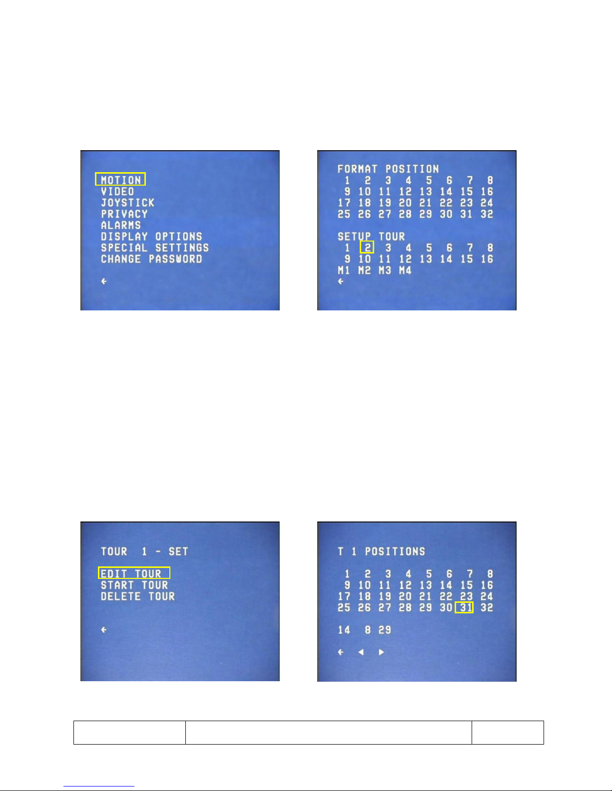
1. Selecting MOTION from SETUP menu allows an operator to set up tours (See Fig 26).
2. Selecting a slow (1-8) or fast (9-16) tour from the MOTION menu takes the operator to the SETUP
TOUR menu (See Fig 27).
3. A slow tour has a dwell time of 6 seconds and travel time between positions of 10 seconds. A fast
tour has a dwell time of 6 seconds and a travel time between positions of 1 second.
Fig 26 Setup menu screen Fig 27 Motion menu screen
1. SETUP TOUR menu displays the selected tour and its status.
2. EDIT TOUR takes the operator to the EDIT TOUR menu (See Fig 28).
3. START TOUR will exit the menu structure and execute the currently selected tour.
4. DELETE TOUR deletes the currently selected tour.
Note: START TOUR and DELETE TOUR will only function if the selected tour has been set.
5. In the EDIT TOUR menu, the tour can be set up by selecting the positions wanted for that tour. Each
tour can contain up to 8 positions (See Fig 29).
6. Selecting the FORWARD arrow confirms the new tour setup, the BACKWARD arrow deletes the last
position from the tour, and the BACK arrow cancels the setup and returns to its previous state.
Fig 28 Setup Tour menu screen Fig 29 Edit Tour menu screen
Page 25
This is the property of Overview Limited, no copying without
permission
except as permitted by copyright
law
23 May 2013
25
Motion Menu – Setting Up a Mimic Tour
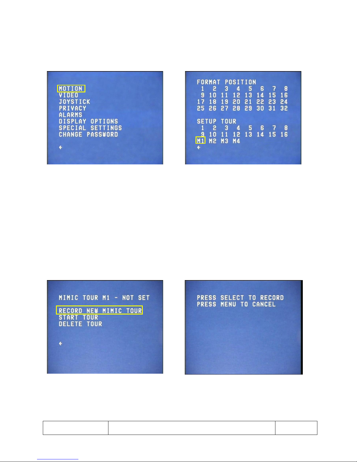
1. Selecting MOTION from SETUP menu allows an operator to set up mimic tours (See Fig 30).
2. Selecting a mimic (MX) tour from the MOTION menu (See Fig 30) takes the operator to the SET UP
MIMIC Tour menu (See Fig 32).
Fig 30 Setup menu screen Fig 31 Motion menu screen
1. The top line of the SET UP MIMIC TOUR menu displays the currently selected mimic tour and its
status (See Fig 32).
2. RECORD NEW MIMIC TOUR takes the operator to the RECORD NEW MIMIC TOUR screen.
3. START TOUR leaves the menu structure and starts the currently selected mimic tour.
4. DELETE TOUR deletes the currently selected mimic tour.
5. After selecting RECORD NEW MIMIC TOUR the Dome can be moved to the starting position of the
tour, and recording started by pressing the button. If the operator cancels the recording they are
taken back to normal joystick operation (See Fig 33).
Fig 32 Set up Mimic Tour screen Fig 33 Record New Mimic Tour Screen
Page 26
This is the property of Overview Limited, no copying without
permission
except as permitted by copyright
law
23 May 2013
26
Video Settings
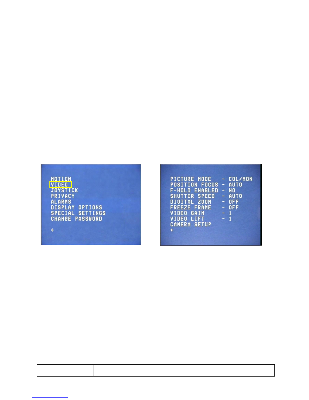
1. Selecting VIDEO from the SETUP menu takes the operator to the VIDEO SETTINGS menu (See Fig 34).
2. From the VIDEO SETTINGS menu the operator can change the following options (See Fig 35):
a. PICTURE MODE: toggles between COL/MON, COLOUR and MONO. This sets up which display
mode is used by the camera.
b. POSITION FOCUS: toggles between AUTO and MANUAL. This controls the operator’s ability
to adjust the focus of the camera using the control panel when setting preset positioning.
c. FOCUS HOLD: toggles between ON and OFF. Disables auto focus to maintain a specific point
of focus.
d. SHUTTER SPEED: toggles between AUTO, NORMAL, 1/10000, 1/3500, 1/1000 or 1/215 of a
second.
e. DIGITAL ZOOM: toggles between ON and OFF.
f. FREEZE FRAME: toggles between ON and OFF. When the freeze frame is on the camera will
only change its display each time it arrives at a new position.
g. VIDEO GAIN and VIDEO LIFT: both have 8 settings between 1 and 8. This allows for the
picture to be set up depending on variation in cable lengths and the environment that the
Dome is in.
h. CAMERA SETUP: takes you to a camera setup menu to adjust key parameters of the camera.
Fig 34 Setup menu screen Fig 35 Video Settings menu screen
Page 27
This is the property of Overview Limited, no copying without
permission
except as permitted by copyright
law
23 May 2013
27
Joystick Settings
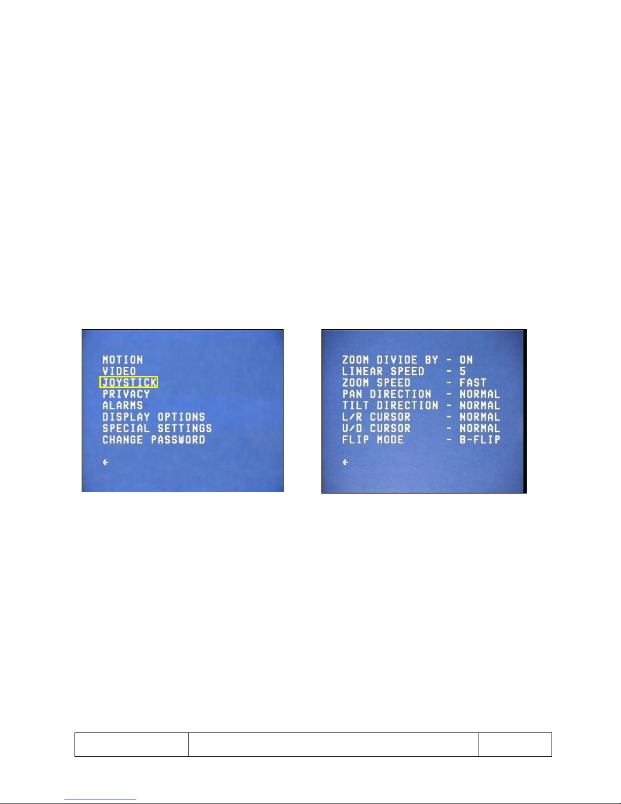
1. Selecting JOYSTICK from the SETUP menu takes the operator to JOYSTICK SETTINGS menu, which
allows the operator to adjust the control settings of the Dome (See Fig 36).
2. From the JOYSTICK SETTINGS menu the following features can be adjusted (See Fig 37):
a. ZOOM DIVIDE BY: toggles between ON and OFF controls whether the speed of the Dome is
scaled with zoom or not.
b. LINEAR SPEED: toggles between 1 and 8. This is a speed factor of the Dome irrespective of
zoom. 8 is the fastest speed, 1 is the slowest.
c. ZOOM SPEED: toggles between SLOW, NORMAL and FAST to control the speed that the
Dome zooms at.
d. PAN/TILT DIRECTION: toggles between NORMAL and REVERSE and manages joystick control
of the Dome.
e. LEFT/RIGHT (L/R) CURSOR: toggles between NORMAL and REVERSE for horizontal control
within the menu structure.
f. UP/DOWN (U/D) CURSOR: toggles between NORMAL and REVERSE for vertical control within
the menu structure.
g. FLIP MODE: toggles between OFF and B-FLIP (Bottom flip) to control the Dome operation
when reaches the vertical position. B-FLIP performs a 180° pan rotation.
Fig 36 Setup menu screen Fig 37 Joystick Settings menu screen
Page 28
This is the property of Overview Limited, no copying without
permission
except as permitted by copyright
law
23 May 2013
28
Privacy Menu
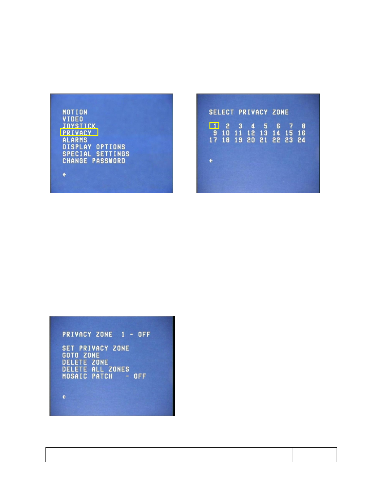
1. Selecting PRIVACY from the SETUP menu takes the operator to the SET UP PRIVACY ZONE menu (See
Fig 38).
2. The Dome can store 24 privacy zones. The camera can only display 8 privacy zones on the screen at
any one time (See Fig 39). If there are more than 8 privacy zones in view only the first 8 will be
displayed.
Fig 38 Setup menu screen Fig 39 Setup Privacy Zone menu screen
1. Selecting a zone number from the SET UP PRIVACY ZONE menu takes the operator to the FORMAT
PRIVACY ZONE menu (See Fig 40).
2. The top line of the FORMAT PRIVACY ZONE menu displays the selected zone number and its status.
3. SET PRIVACY ZONE re-assigns the zone location to the current Dome view.
4. GOTO ZONE exits the menu structure and takes the operator to the location of the currently selected
zone.
5. DELETE ZONE deletes the currently selected privacy zone.
6. DELETE ALL ZONES will delete all set privacy zones.
Note: GOTO ZONE and DELETE ZONE only function if the currently selected patch has been set.
Fig 40 Format Privacy Zone menu screen
Page 29
This is the property of Overview Limited, no copying without
permission
except as permitted by copyright
law
23 May 2013
29
Alarms Menu – Alarm Setup
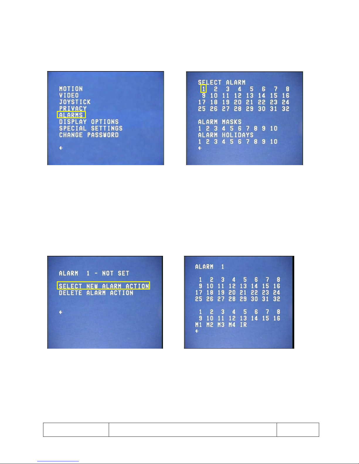
1. Selecting ALARMS from the SETUP menu takes the operator to the ALARM SETUP menu where alarm
actions, masks and holidays can be formatted (See Fig 41 & 42).
2. Selecting an alarm takes the operator to the FORMAT ALARM menu (See Fig 43).
Fig 41 Setup menu screen Fig 42 Alarm Setup menu screen
1. On the top line of the FORMAT ALARM menu, the currently selected alarm number is displayed along
with its status (See Fig 43).
2. SELECT NEW ALARM ACTION takes the operator to the ALARM ACTION menu (See Fig 44).
3. DELETE ALARM ACTION cancels the action set for the currently selected alarm.
4. In the ALARM ACTION menu, any position, four or mimic tour can be selected as the alarm action.
Fig 43 Format Alarm menu screen Fig 44 Alarm Action menu screen
Page 30
This is the property of Overview Limited, no copying without
permission
except as permitted by copyright
law
23 May 2013
30
Alarms Menu – Alarm Mask Setup
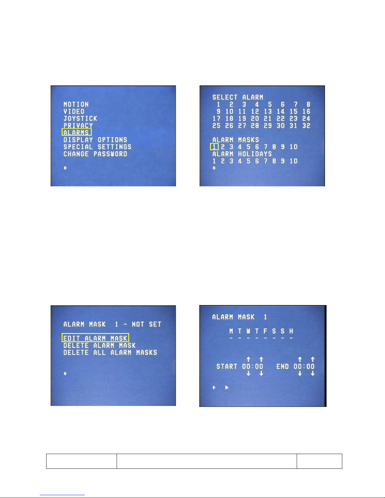
1. Selecting ALARMS from the SETUP menu takes the operator to the ALARM SETUP menu where alarm
actions, masks and holidays can be formatted (See Fig 45 & 46).
2. Selecting an alarm mask from the ALARM SETUP MENU takes the operator to the ALARM MASK
SETUP menu (see Fig 47).
Fig 45 Setup menu screen Fig 46 Alarm Setup menu screen
1. The top line of the ALARM MASK SETUP menu displays the currently selected alarm mask and its
status (See Fig 47).
2. By selecting EDIT ALARM MASK the operator is taken to the EDIT ALARM MASK menu.
3. DELETE ALARM MASK deletes the currently selected alarm mask.
4. DELETE ALL ALARM MASKS deletes all of the alarm masks that have been set up.
5. The EDIT ALARM MASK menu allows the operator to setup the days (H stands for holiday), and the
start and end time for the mask (See Fig 48).
6. A day which is selected for an alarm mask will have an X under it, and on that day, between the
START and END times, all alarms will be inactive.
Fig 47 Alarm Mask Setup menu screen Fig 48 Edit Alarm Mask screen
Page 31
This is the property of Overview Limited, no copying without
permission
except as permitted by copyright
law
23 May 2013
31
Alarms Menu – Alarm Holiday Setup
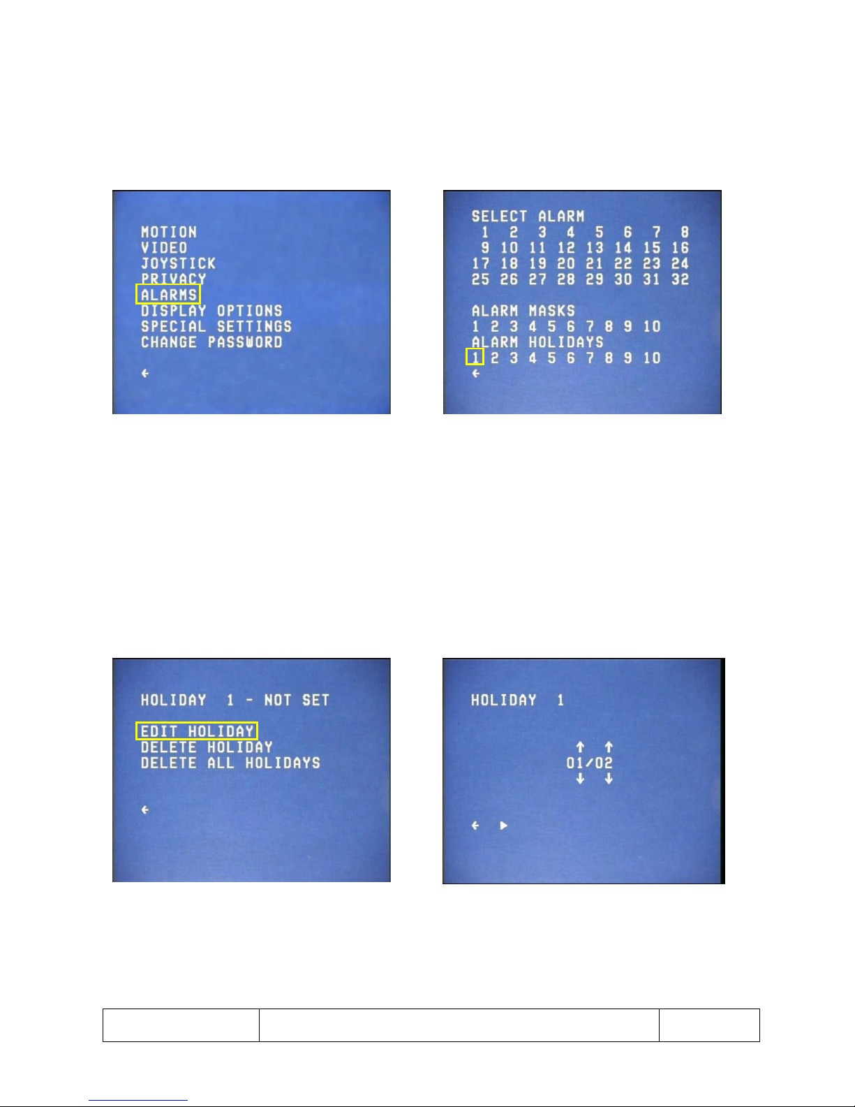
1. Selecting ALARMS from the SETUP menu takes the operator to the ALARM SETUP menu where alarm
actions, masks and holidays can be formatted (See Fig 49 & 50).
2. Selecting an alarm holiday from the ALARM SETUP menu takes the operator to the FORMAT ALARM
HOLIDAY menu (See Fig 51).
Fig 49 Setup menu screen Fig 50 Alarm Setup menu screen
1. The top line of the FORMAT ALARM HOLIDAY menu displays the currently selected alarm holiday and
its status. If the holiday has been set, the date of the holiday will be displayed as the status.
2. DELETE HOLIDAY deletes the currently selected alarm holiday.
3. DELETE ALL HOLIDAYS deletes all the alarm holidays that have been set up.
4. By selecting EDIT HOLIDAY the operator is taken to the EDIT HOLIDAY menu, where the date of the
alarm holiday can be adjusted (See Fig 51 & 52).
5. Holidays are used when setting up alarm masks – so that alarms can be enabled or disabled for
specific days such as bank holidays.
Fig 51 Format Alarm Holiday menu screen Fig 52 Edit Holiday screen
Page 32
This is the property of Overview Limited, no copying without
permission
except as permitted by copyright
law
23 May 2013
32
Display Options
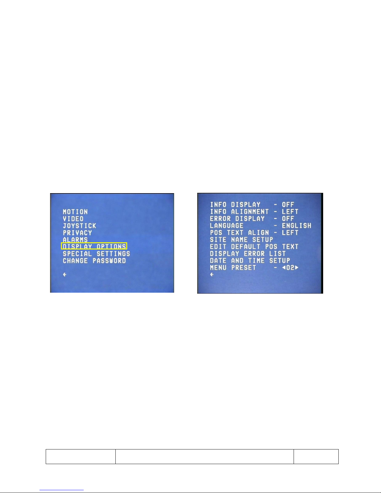
1. Selecting DISPLAY OPTIONS from the SETUP menu takes the operator to the DISPLAY OPTIONS menu,
where options regarding display information can be adjusted (See Fig 53 & 54).
2. From the DISPLAY OPTIONS menu the following features can be adjusted:
a. INFO DISPLAY: toggles between ON and OFF to control whether the Dome information is
displayed on the screen.
b. INFO ALIGNMENT: toggles between LEFT and RIGHT to control where on the screen the
Dome information is displayed.
c. ERROR DISPLAY: toggles between ON and OFF to control whether error warnings are
displayed.
d. LANGUAGE: selects the language which the menu structure is displayed in.
e. POS TEXT ALIGN: toggles between LEFT and RIGHT to control where on the screen the
position text is displayed.
f. SITE NAME SETUP: This text is used to add the site name to the OSD.
g. EDIT DEFAULT POS TEXT – (See Fig 55 & 56, page 33).
h. DISPLAY ERROR LIST – (See Fig 57 & 58, page 33).
i. DATE AND TIME SETUP – (See page 34).
Fig 53 Setup menu screen Fig 54 Display Options menu screen
Page 33
This is the property of Overview Limited, no copying without
permission
except as permitted by copyright
law
23 May 2013
33
Display Options – Editing Default Position Text
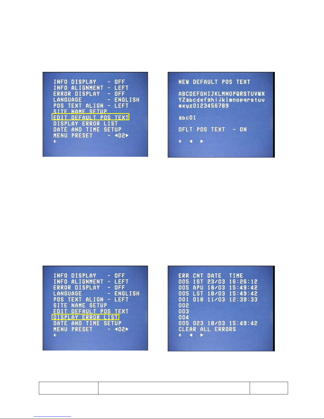
1. Selecting EDIT DEFAULT POS TEXT from the DISPLAY OPTIONS menu takes the operator to the menu,
where the default position text can be edited (See Fig 55 & 56).
2. This text is used when a preset position has no display text of its own and is accompanied by the
relevant position number.
Fig 55 Display Options menu screen Fig 56 Edit Default Position Text screen
1. Selecting DISPLAY ERROR LIST from the DISPLAY OPTIONS menu takes the operator to the DISPLAY
ERROR LIST screen, which displays the errors that have occurred, and the date and time of their
occurrence (See Fig 57 & 58).
2. CNT (count) is the number of times an error has occurred, and DATE and TIME display when that
error has last occurred.
3. The 1
st
3 lines display: the 1
st
error since error logging started (1st); the 1
st
error since the Dome was
powered up (APU-After Power Up); and the last error (LST) that occurred.
4. CLEAR ALL ERRORS clears the error log from the Dome memory. Selecting the FORWARD arrow takes
the operator to the next page of errors; the BACKWARD arrow takes the operator to the previous
page of errors.
Fig 57 Display Options menu screen Fig 58 Display Error List screen
Page 34
This is the property of Overview Limited, no copying without
permission
except as permitted by copyright
law
23 May 2013
34
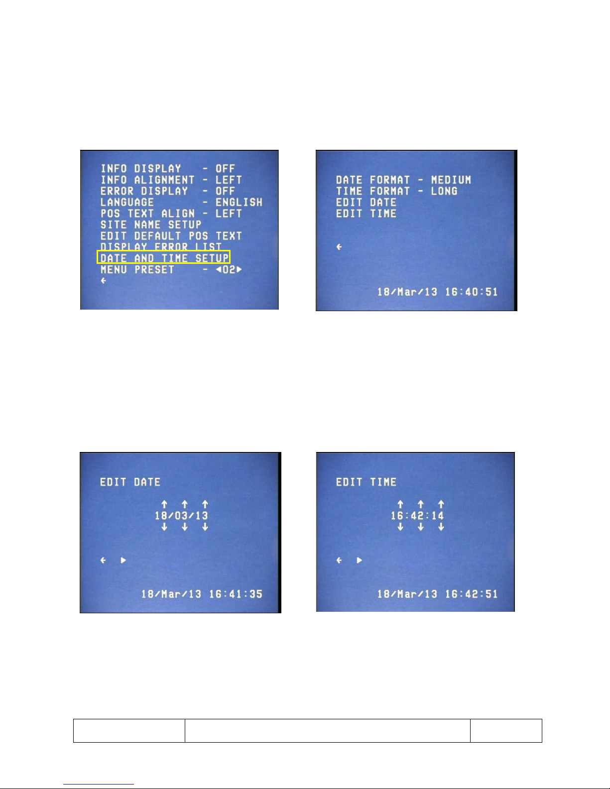
Display Options – Setting Up Date and Time
1. Selecting DATE AND TIME SETUP from the DISPLAY OPTIONS menu takes the operator to the DATE
AND TIME menu (See Fig 59 & 60).
2. In DATE AND TIME menu, selecting DATE FORMAT changes the displayed date format between OFF,
SHORT, MEDIUM and LONG.
3. Selecting TIME FORMAT changes the time format between OFF, SHORT, MEDIUM and LONG.
Fig 59 Display Options menu screen Fig 60 Date and Time menu screen
1. Selecting EDIT DATE option from the DATE AND TIME menu takes the operator to the EDIT DATE
menu where the date can be set (See Fig 61).
2. Selecting EDIT TIME option from the DATE AND TIME menu takes the operator to the EDIT DATE
menu where the time can be set (See Fig 62).
Fig 61 Edit Date screen Fig 62 Edit Time screen
Page 35
This is the property of Overview Limited, no copying without
permission
except as permitted by copyright
law
23 May 2013
35
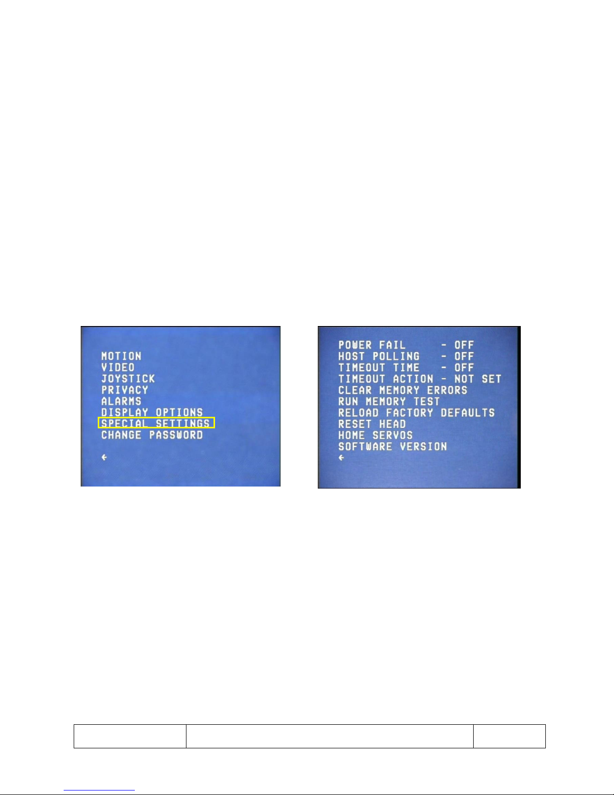
Special Settings
1. SPECIAL SETTINGS menu gives access to the technical features of the Dome (See Fig 63).
2. From the SPECIAL SETTINGS menu the following features can be adjusted (See Fig 64):
a. POWER FAIL: toggles between P/T/JOY, P/T and OFF and controls what type of action is
stored when the Dome is powered down. P/T/JOY means that the Dome will return to a
position, tour or joystick position; P/T will return to a tour or a position; and OFF executes no
power fail action.
b. HOST POLLING: toggles between ON and OFF. This is used for some control panels that
require a heartbeat.
c. TIMEOUT TIME: (See Fig 65 & 66, page 36).
d. TIMEOUT ACTION: (See Fig 67 & 68, page 36).
e. CLEAR MEMORY ERRORS: checks and repairs any errors in the memory
f. RUN MEMORY TEST: tests the validity of the Dome’s memory
g. RELOAD FACTORY DEFAULTS: resets the Dome to its default settings.
h. RESET HEAD: power cycles the Dome
i. HOME SERVOS: homes the Dome to its closest calibration point
j. SOFTWARE VERSION: displays information about the Dome’s software
Fig 63 Setup menu screen Fig 64 Special Settings menu screen
Page 36
This is the property of Overview Limited, no copying without
permission
except as permitted by copyright
law
23 May 2013
36
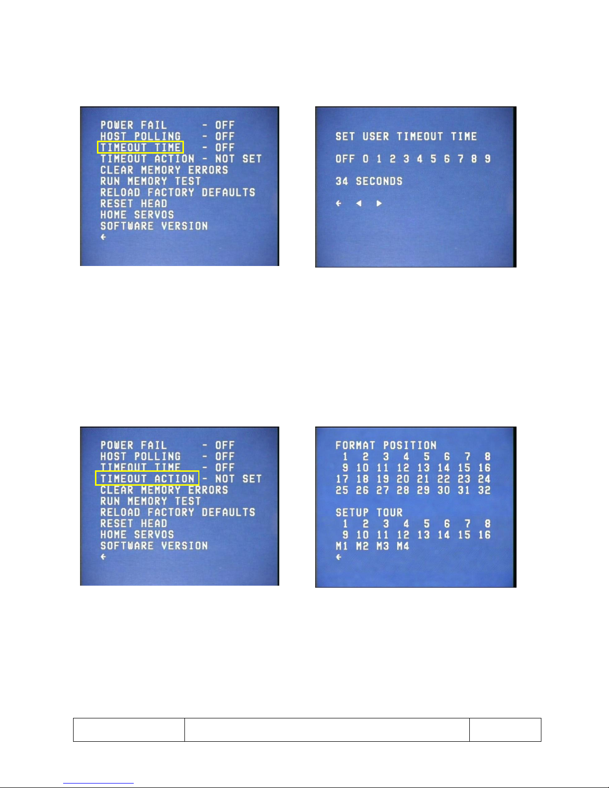
Special Settings – Setting Timeout Time
1. By selecting TIMEOUT TIME from the SPECIAL SETTINGS menu, the operator can set the time after
which the Dome executes its timeout action (See Fig 65 & 66).
Fig 65 Special Settings menu screen Fig 66 Timeout Time screen
Special Settings – Setting Timeout Action
1. By selecting TIMEOUT ACTION from the SPECIAL SETTINGS menu, the operator can set which default
action the Dome will execute after a user timeout has occurred (See Fig 67 & 68).
2. Any tour or preset position can be set as the timeout action.
Fig 67 Special Settings menu screen Fig 68 Timeout Action menu screen
Page 37
This is the property of Overview Limited, no copying without
permission
except as permitted by copyright
law
23 May 2013
37
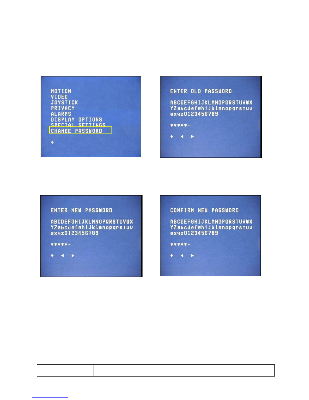
Changing the Password
1. CHANGE PASSWORD menu allows the user to change the password used to enter the SETUP menu
(See Fig 69-72).
2. If the wrong password is entered at any point the current CHANGE PASSWORD screen will be
redisplayed. This process can be cancelled at any time by using the BACK button or EXIT menu
command.
Fig 69 Setup menu screen Fig 70 Change Password screen
Fig 71 Enter New Password screen Fig 72 Confirm New Password screen
Page 38

This is the property of Overview Limited, no copying without
permission
except as permitted by copyright
law
23 May 2013
38
Warranty Return Procedure
Use the following procedure to return a unit to Overview Ltd:
Telephone or write to Overview Ltd, for a Return Authorization (R.M.A.).
Do not ship the equipment until you receive the RMA.
Overview Ltd.
55 Bendon Valley
London
SW18 4LZ
Tel: +44 (0) 208 875 0984
Fax: +44 (0) 208 8750983
Email: [email protected]
Do not return goods to Overview without an RMA.
 Loading...