

Verve VTST-LNV WiSPER Installation Manual
Installation Guide
VTST-LNV WiSPER Thermostat
Line Voltage
Application:
This thermostat is a line voltage heating and cooling digital temperature
control designed to operate either 2 or 4-pipe fan coil systems, but it
can also be configured to operate line voltage PTHP/PT
This thermostat also has the capability to receive and transmit to
EnOcean enabled wireless products. Please see programming
instructions for more details. Switching of load circuits is through relay
contacts (see specifications for applicable load ratings). The fan
cycles on/off with calls for heating or cooling or can be on continuously
in either low or high speed when configured as a heat pump or on
continuously in either low, medium or high speed when configured as
a fan coil. The control can be placed in economy mode or stop mode
with 40°F freeze protection. This thermostat operates at a single
setpoint with automatic changeover
Specifications:
mperature Monitor Range: 32.2°F to 99.9°F (0.0°C to 37.7°C)
Te
Setpoint Range: 60.0°F to 85.0°F (15.5°C to 29.5°C)
*Setpoint: 72.0°F (22.0°C)
*Comfort Limits: 65.0°F (18.5°C) cooling
85.0°F (29.5°C) heating
Display Format: Liquid Crystal Display (LCD)
Backlight: EL blue green
Sampling Rate: Every 15 seconds
Accuracy: ± 1°F (0.5°C)
Power Source: 120VAC to 277VAC (102 minimum to 304 maximum)
Load Rating:
1/4 HP 3 speed or 2 speed fan motors:
Voltage
1/4HP FLA
Heat/Cool
Pilot Duty
Single speed fan motors:
Voltage
1/6HP FLA
Heat/Cool
Pilot Duty
*Fan Control:
Fan Coil - Selectable: Auto cycle, Low, Medium, High, Economy, Stop
Heat Pump - Selectable: Auto cycle, Low, High, Economy, Stop
Heat/Cool Control:
Fan Coil: 1 heat and 1 cool circuit
Heat Pump: 2 heat and 1 cool circuit
*Economy Limits:
Maintains room temperature between 60.0°F and 85.0°F
(15.5°C and 29.5°C) when thermostat is in economy (ECON) mode
*Fan Purge Timer: 30 seconds
Anti-short Cycle: 3 minute hold in no call state at all times
*Cycle Rate:
Fan Coil: 8 cycles per hour
Heat Pump: 6 cycles per hour
* Differential: 0.4°F
Display Mode: Setpoint temperature
*
* System Function: Heat and Cool
*See Field Programming Instructions
120V
AC
5.8A
125VA
(1.0A)
120VAC
4.4A
240VA
(2.0A)
.
208VAC 220 - 240VAC
3.1A
125VA
(0.6A)
208VAC 220 - 240VAC
2.4A
240VA
(1.15A)
125VA
(0.52A)
240VA
(1.0A)
AC systems.
277VAC
2.4A2.9A
125VA
(0.45A)
277VAC
1.9A2.2A
240VA
(0.87A)
INSTALLATION:
This device should be installed and serviced by a qualified technician.
Mount this control ONLY
1. Caution: HIGH VOLTAGE - Disconnect power supply before
servicing.
2. All wiring must comply with applicable codes and ordinances.
All wiring must have insulation rated 600VAC minimum.
Supply wires must be suitable for at least 105°C.
Suitable for insulated walls.
3. A thorough check-out of the system should be made after
installation is complete.
4. If fan motor is larger than 1/4 HP and/or electric heaters are used
for heating, additional power relays will be required
5. If retrofitting old thermostat, remove old thermostat from the
junction box, carefully noting the wire connections on the old unit.
Record wire color and terminal legends in spaces provided.
Old thermostat
wire function
Power Feed
Load Feed
Low Fan
Medium Fan
High Fan
Reverse V
Disconnect old thermostat and remove any existing backplate or
mounting plate.
6. Install the mounting bracket to the junction box with the two long
mounting screws provided.
Note: If application involves a double ganged junction box,
a backplate will be required for a complete installation.
Please consult your supplier.
7. From the wire chart found in step 5, assign, according to function,
the cable wire colors to the thermostat wire legend provided below.
Note: The control feed and the load feed will be connected together
for the 4-pipe installation. If this is a new installation, record the cable
wire colors in the thermostat legend provided below.
New Stat Wire
Function
Control Feed
Load Feed
Neutral
Heat
Cool
Low Fan
Medium Fan
High Fan/Reverse V
Earth Ground
8. Connect the thermostat wires to the cable wires recorded in step 7.
Be sure to connect green wire to earth ground.
9. Push the wires into the junction box. Tilt
the thermostat so that the bottom of the
thermostat is resting on the mounting tabs
of the mounting plate. Push the top of the
thermostat towards the wall and secure into
place with the self-tapping screw as shown
to the right.
10. Turn power on. At start up, the low fan will automatically run for
three minutes to cycle room air.
If cooling or heating is required, it may become active after the
first 30 seconds of fan run time.
1
to a grounded metallic box.
Neutral
Heat
Cool
alve
New Stat Wire
Color
Black
Orange
White
Red
Blue
Yellow
Yellow/Black
alve
Yellow/Red
Green
Cable
wire color
Cable Wire Color
Standard
Junction
box
BLACK
BLACK
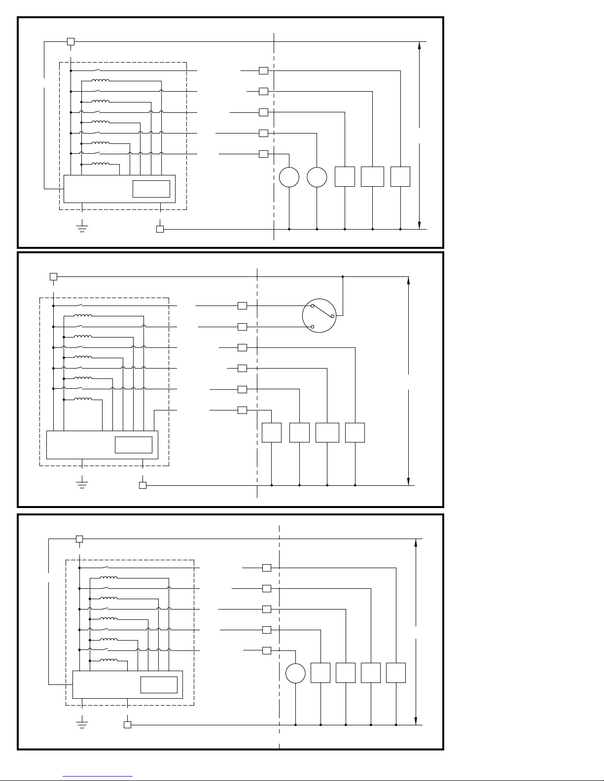
4 pipe FAN COIL (3 speed fan)
R
ORANGE
THERMOSTAT INTERNAL
R = CONTROL FEED
N = NEUTRAL
MICROPROCESSOR
CONTROLLER
GREEN
888.8
WHITE
N
GH = HIGH FAN SPEED
GM = MEDIUM FAN SPEED
GL = LOW FAN SPEED
HT = HEAT VALVE
CL = COOL VALVE
2 pipe FAN COIL with aquastat (3 speed fan)
R
THERMOSTAT INTERNAL
RED
BLUE
YELLOW W/
RED STRIPE
YELLOW W/
BLACK STRIPE
YELLOW
YELLOW W/
RED STRIPE
YELLOW W/
BLACK STRIPE
YELLOW
RED
BLUE
MECHANICAL
SYSTEM COMPONENTS
GH
GM
GL
HIGH
FAN
RELAY
LINE
VOLTAGE
HT
CL
MEDIUM
HTG
LOW
FAN
RELAY
FAN
RELAY
CLG
VALVE
VALVE
Fan Coil Note:
If the mechanical system has only
two fan speeds Yel low - low fan
Yel low w/ Black Stripe - high fan
Yel low w/ Red Stripe- not used
NOTE:
Green wire is to be attached to
earth ground.
Aquastat or
Hot pipe
HT
Cool pipe
CL
GH
GM
GL
season change
switch
MECHANICAL
SYSTEM
COMPONENTS
LINE
VOLTAGE
MICROPROCESSOR
CONTROLLER
GREEN
ORANGE
BLACK
GREEN
888.8
HEAT PUMP
R
THERMOSTAT INTERNAL
MICROPROCESSOR
CONTROLLER
WHITE
N
WHITE
N
ORANGE
R = CONTROL FEED
N = NEUTRAL
GH = HIGH FAN SPEED
GM = MEDIUM FAN SPEED
GL = LOW FAN SPEED
HT = HEAT VALVE
CL = COOL VALVE
888.8
LF
YELLOW W/
BLACK STRIPE
YELLOW
RED
BLUE
YELLOW W/
RED STRIPE
R = CONTROL FEED
N = NEUTRAL
GH = HIGH FAN SPEED
GL = LOW FAN SPEED
W2 = AUXILIARY HEAT
Y = COMPRESSOR
RV = REVERSING VALVE
VALVE
GH
GL
W2
Y
RV
MEDIUM
LOW
FAN
FAN
RELAY
RELAY
MECHANICAL
SYSTEM COMPONENTS
COMP
RELAY
AUX
HEAT
RELAY
REV
VALVE
HIGH
FAN
RELAY
LOW
FAN
RELAY
HIGH
FAN
RELAY
LINE
VOLTAGE
2
 Loading...