

Page 1
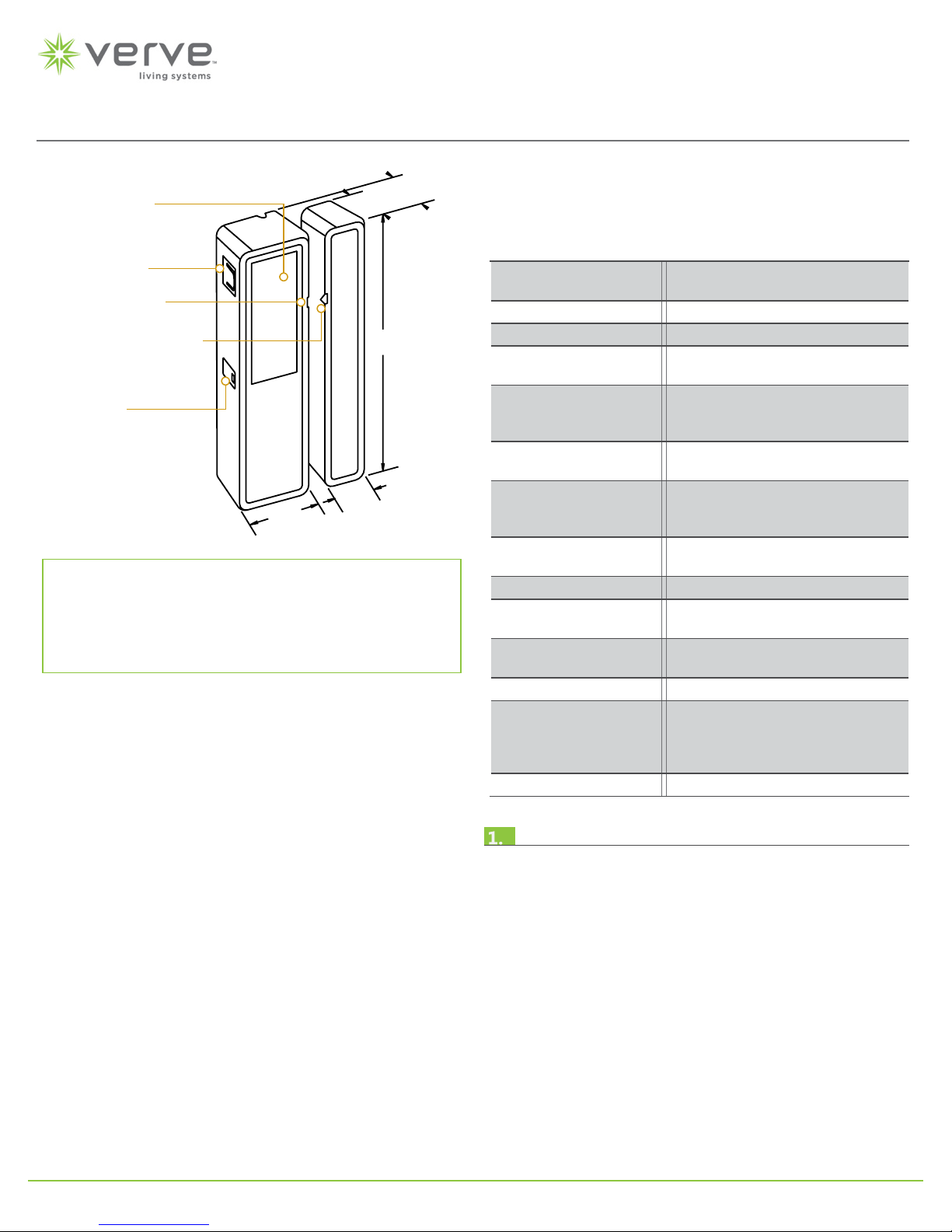
Door / Window Sensor
Solar P
Link Button
Alignment Ar
(Sensor)
LED Display
Installation Guide
Model: EDWS
anel
0.5”
12.7mm
row
Alignment Arrow
(Magnet)
0.47”
12mm
Package Contents
▪ Sensor and magnet
▪ 4 screws
0.83”
21mm
Tools Required
▪ Screwdriver
▪ Leveling tool
▪ Light meter
Product Description
For use as both:
▪ Entry Door Sensing
▪ Outside Door / Window Sensing
The Verve Door/Window Sensor provides energy savings by
detecting when a door or window opens or closes.
It is a wireless solar-powered sensor that can be used on its own
to detect the open and closed status of entry doors or windows,
or it can be linked with occupancy sensors to more accurately
track when a room is occupied or vacant.
The sensor is easy to install on door and window frames, and
virtually anything indoors that opens and closes.
Features Include:
▪ Sends wireless message to other devices whenever a door or
window opens or closes
▪ Harvests ambient solar energy to power the sensor and send
wireless communication
▪ Mounts easily on standard doors or windows
▪ Works with motion sensors to track room occupancy
3.15”
80mm
0.59”
15mm
▪ Supplemental battery option for extreme low-light condi-
tions
Specications
Power Supply Indoor light energy harvesting
(Optional) Supplemental battery
Transmission Range 80 ft. (25 m)
RF Communications EnOcean 315 MHz , 902 MHz
Charge Time
before Linking
Light Required to
Sustain Operation
Charge Time for
Full Charge
Operating Life in Dark-
ness (after full charge)
EEP (EnOcean
Equipment Prole)
Maximum Sensor Gap 0.25 inch (6.4 mm)
Dimensions (Sensor) 3.15” L x 0.83” W x 0.59” D
Dimensions (Magnet) 3.15” L x 0.47” W x 0.5” D
Weight (Total) 0.97 oz. (27.5 g)
Environment • Indoor use only
Agency Compliance FCC, IC
2.7 hours @ 10 lux
3.7 minutes @ 200 lux
15 lux for 6 actuations/hour
50 lux for 30 actuations/hour
100 lux for 60 actuations/hour
21 hours @ 200 lux (after startup)
42 hours @ 200 lux (cold start)
174 hours: heartbeat only
67 hours @ 10 actuations/hour
10 hours @ 100 actuations/hour
D5-00-01
(80 mm x 21 mm x 15 mm)
(80 mm x 12 mm x 13 mm)
• 32° to 131° F (0° to 55° C)
• 5% to 95% relative humidity
(non-condensing)
Planning
Take a moment to plan for the sensor’s successful operation and
optimal communication with other system components.
Remove the sensor from its packaging and place it under a
strong light to charge it for installation.
▪ Ensure the location provides consistent and adequate light
▪ Install according to the alignment requirements
▪ Determine which sensor prole is appropriate (when linking
with EnOcean-based In-line Switch, Plug-in Switch or HVAC
Setback Modules (refer to the “Linking” and “Sensor Proles”
sections) - otherwise; when linking with 3rd party control-
lers, these proles aren’t relevant
Consider the construction materials, such as metal and concrete,
in the space and obstacles that may interfere with RF signals
p1© 2013 Verve Living Systems
Page 2
estimated time: 20 minutes
Tab lock
Notch
Tab lock
Notch
NotchesNotches
Tab lockTa b lock
Tab lockTa b lock
Door/Window Sensor • Installation Guide
Alignment Requirements
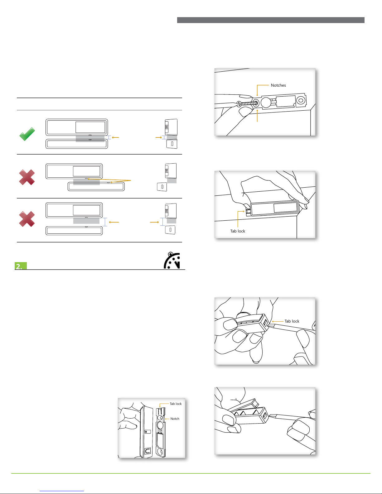
The proximity of the magnet to the sensor is important for
proper detection. The alignment arrows on the sensor and the
magnet must point to each other and the gap between them
must not exceed .25 inch (6.4mm) in any direction.
Alignment Guidelines
Front View End View
gap is 1/4” (6.4mm)
or less
misaligned
arrows
gap is too wide
B. Position the mounting bracket and mark the two mount-
ing screw drill points.
C. Insert the rst screw loosely and level the mounting
bracket.
D. Install the second screw, and then hand-tighten the rst
screw.
E. Snap the sensor onto the mounting bracket where the
notches are located.
Installing
1. Based on your requirements, decide where you want to install the sensor and the magnet. For door installations, locate
the sensor:
• On the knob side of the door jamb, away from hinges.
• At least 1 ft. (30 cm) above the oor to avoid damage.
For window installations, make sure the location does not
expose the sensor to contact with water.
2. Follow the alignment requirements that are described in the
Planning section.
NOTE: For easy access and handling, it is recommends that
the sensor be linked to a transceiver before installing it, see
the Linking section.
3. Install the sensor on the interior side of the xed frame.
A. Remove the mounting
bracket from the sensor.
F. Slide the sensor on the bracket until it snaps into place
on the tab lock.
4. Install the magnet on the moving part of the door or window.
A. Use a screwdriver to press the tab lock and ex the mag-
net cover to remove it.
The cover is removed from the magnet body.
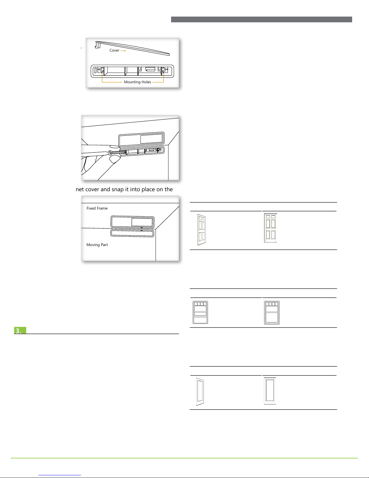
p2© 2013 Verve Living Systems
Page 3
Cover
Mounting Holes
Cover
Mounting Holes
Fixed Frame
Moving Part
Fixed Frame
Moving Part
Door/Window Sensor • Installation Guide
The two mounting
holes are exposed.
B. Position the magnet with the proper spacing and align-
ment, and then install it with the provided screws.
C. Replace the magnet cover and snap it into place on the
tab lock.
NOTE: For low activity applications, the magnet can be
mounted with double-sided tape (not included).
5. Check the alignment arrows and the distance between the
sensor and magnet when the door or window is closed.
TIP: There is a faintly audible click when the sensor and magnet close and open.
The Door/Window Sensor is a Transmit-only Device.
To link the Door/Window Sensor to a transceiver; the transceiver
must rst be powered, within wireless range, and set to accepts
links.
Next, the desired transmitter, or another transceiver, is triggered
to send a special link message. The awaiting transceiver receives
and stores the link permanently so the devices can interact to
provide a variety of intelligent control options.
Sensor Proles
The sensor prole determines how the sensor is used within the
system, whether it is for occupancy detection, HVAC control, or
single load control. How the sensor interacts with other devices
depends on where it is installed and how it is linked. There are
three sensor proles.
NOTE: These proles are supported for linking with EnOcean
EISM (In-line Switch), EPSM (Plug-in Switch), and EHSM (HVAC
Setback) controllers. Consult the manual for the respective controllers to determine the capabilities of the solution.
Entry Door - for Occupancy Detection
For this prole, the sensor is installed on an entry door and
operates with a motion sensor as follows:
Door Opens Door Closes
The door/window ajar
timer starts. If the timer
runs out, shutdown mode
is activated on the HVAC
system.
Window or Patio Door for HVAC Control
For this prole, the sensor is installed on a window or patio door
and operates as follows:
Window Opens Window Closes
The door/window ajar
timer starts. If the timer
runs out, shutdown mode
is activated on the HVAC
system.
The door/window ajar timer
is reset if all monitored doors
and windows are closed. The
vacancy check timer starts,
if the motion sensor detects
occupancy, normal mode is
activated on the HVAC system.
The door/window ajar timer
is reset if all monitored doors
and windows are closed.
Normal mode is activated on
the HVAC system.
Linking
Two or more EnOcean-based devices can be linked and congured to provide the desired control. There are two basic types of
devices in the system; transmitters and transceivers.
▪ Transmit-only: Transmitters are simple energy-harvesting
devices that send RF messages to communicate a condition,
level, or state. Transmitters can only be linked to transceivers.
Examples > Self-powered Light Switches, Occupancy Sensors
▪ Transmit & Receive: Transceivers are controlling devices
that send as well as receive RF messages. They also process
relevant control logic, and actuate the appropriate outputs
(switching a light on or off for example). Transceivers can be
linked with transmitters as well as other transceivers. A transceiver can have up to 30 devices linked to it.
Examples > Relays, Gateways
Closet Door for Single Load Control
For this prole, the sensor is installed on a closet door and operate as follows because it is the only linked device:
Door Opens Door Closes
The switched auto-off timer
starts and the light turns
on. If the timer runs out the
light turns off.
The light turns off.
p3© 2013 Verve Living Systems
Page 4
Tab lock
Notch
Tab lock
Notch
Contact TerminalsContact Terminals
Door/Window Sensor • Installation Guide
To Link or Unlink a Sensor
When a Door/Window Sensor is linked, the position of the
magnet indicates to the transceiver which type of sensor prole
is being used.
1. Set the desired transceiver to Accept a Link.
2. Do one of the following according to the desired prole:
A. Entry door for occupancy detection, place the magnet
beside the sensor (closed position).
B. Window or patio door for HVAC control, move the mag-
net way from the sensor (open position).
C. Closet door for single load control, move the magnet
away from the sensor (open position).
3. Press the Link button on the sensor once.
The Set button on the transceiver
will be solid green for 3 seconds.
The device is now linked.
Installing Supplemental Battery (optional)
If the sensor is installed where the light levels are consistently
too low or there are days of darkness, battery power can be
used to supplement the solar energy harvester. Only use a
CR1216 battery.
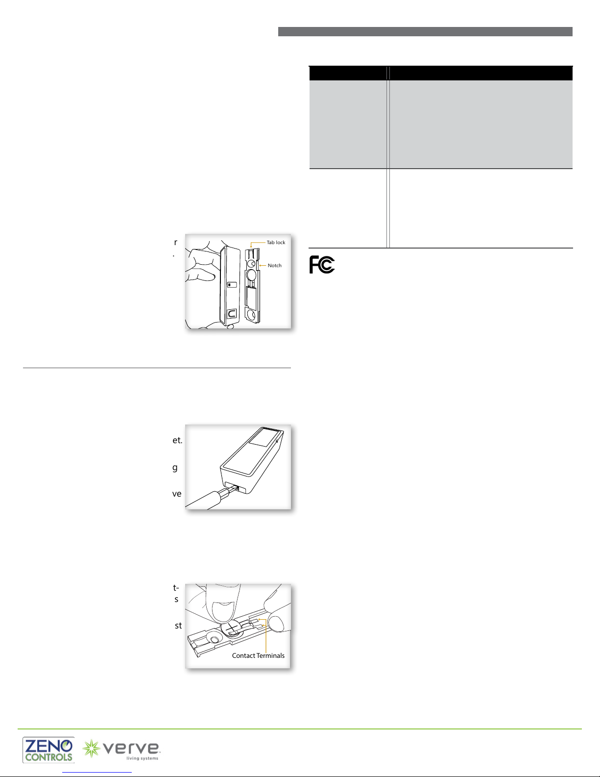
1. Press the tab lock to release the
sensor from the mounting bracket.
2. Slide the sensor about ½” (1 cm)
and remove it from the mounting
plate.
3. Insert the battery with the positive
pole (+) up and slide it between
the two contact terminals with
your nger.
WARNING: Ensure the battery is properly oriented. Improper
handling of lithium batteries may result in heat generation,
explosion, or re.
4. Replace the sensor on the mount-
ing plate and slide it until it snaps
into place.
5. Open and close the contact to test
for power.
6. There should be a faintly audible
click and a fast LED blink.
Troubleshooting
Problem Solution Checklist
The sensor does not
generate a wireless
message
The linked device
does not respond
to wireless messages
902 MHz: Contains: 315 MHz: Contains:
FCC: SZV-STM311U FCC: SZV-STM311C
IC: 5713A-STM311U IC: 5713A-STM311C
This device complies with part 15 of the FCC rules and Industry Canada ICES-003. Operation is subject
to the following two conditions: (1) This device may not cause harmful interference, and (2) this device
must accept any interference received, including interference that may cause undesired operation.
IMPORTANT! Any changes or modications not expressly approved by the party responsible for
compliance could void the user’s authority to operate this equipment.
Le présent appareil est conforme aux CNR d’Industrie Canada applicables aux appareils radio exempts
de licence. L’exploitation est autorisée aux deux conditions suivantes: (1) l’appareil ne doit pas produire
de brouillage, et (2) l’utilisateur de l’appareil doit accepter tout brouillage radioélectrique subi, meme
si le brouillage est susceptible d’en compromettre le fonctionnement.
IMPORTANT! Tous les changements ou modications pas expressément approuvés par la partie
responsable de la conformité ont pu vider l’autorité de l’utilisateur pour actioner cet équipment.
▪ Verify there is a faintly audible click when the
contact is closed and opened
▪ Verify the LED blinks once when the contact is
closed and opened
▪ Verify the solar cell is charged properly
▪ Check that the magnet is oriented to the sen-
sor properly
▪ Check that the alignment arrows are not
spaced more than .25 inch (6.4 mm)
▪ Check for environment or range issues. Tip:
Reorienting the sensor may overcome adverse
RF conditions
▪ Verify the device is linked
▪ Check the transceiver connection and the wir-
ing for errors
▪ Check if appropriate devices are linked accord-
ing to good system planning
Verve Living Systems is a registered brand of
ZENO Controls, LLC
(877) 874-8774
p4
 Loading...