

Vertiv Tech Co., Ltd. NetSure 2100 A31-S1 User Manual

NetSure 2100 A31-S1 Subrack Power System
User Manual
Version
V1.1
Revision date
December 31, 2017
BOM
31013614
Vertiv provides customers with technical support. Users may contact the nearest Vertiv local sales office
or service center.
Copyright © 2017 by Vertiv Tech Co., Ltd.
All rights reserved. The contents in this document are subject to change without notice.
Vertiv Tech Co., Ltd.
Address: Block B2, Nanshan I Park, No.1001 Xueyuan Road, Nanshan District, Shenzhen, 518055, P.R.
China
Homepage: www.VertivCo.com
E-mail: overseas.support@vertivco.com
Safety Precautions
To reduce the chance of accident, please read the safety precautions carefully before operation. The ‘Caution,
Notice, Warning, Danger’ in this book do not represent all the safety points to be observed, and are only
supplement to various safety points. Therefore, the installation and operation personnel must be strictly trained
and master the correct operations and all the safety points before operation.
When operating Vertiv products, you must strictly observe the safety rules in the industry, the general safety
points and special safety instructions specified in this book.
Electrical Safety
I. Hazardous voltage
Danger
Danger
Some components of the power system carry hazardous voltage in operation. Direct contact or indirect contact through
moist objects with these components will result in fatal injury.
Observe safety rules in the industry when installing the AC power system. The installation personnel must be
licensed to operate high voltage and AC power.
In operation, the installation personnel are not allowed to wear conductive objects such as watches, bracelets,
bangles or rings.
When you find water or moisture is on the cabinet, then turn off the power immediately. In moist environment,
precautions must be taken to keep moisture out of the cabinet.
‘Prohibit’ warning label must be attached to the switches and buttons that are not permitted to operate during
installation.
Danger
Danger
High voltage operation may cause a fire and an electric shock. The connection and wiring of AC cables must be in
compliance with the local rules and regulations. Only those who are licensed to operate high voltage and AC power can
perform high voltage operations.
Danger
Danger
To avoid electric shock hazard of outdoor environment and outdoor equipment, the non-professionals are prohibited to
operate or maintain the power system.
III. Tools
Warning
In high voltage and AC operation, special tools must be used. No common or self-carried tools should be used.
IV. Thunderstorm
Danger
Danger
Never operate on high voltage, AC, iron tower or mast in the thunderstorm.
In thunderstorms, a strong electromagnetic field will be generated in the air. Therefore the equipment should be
well earthed in time to avoid damage by lightning strikes.
V. ESD
Note
The static electricity generated by the human body will damage the static sensitive elements on PCBs, such as large-scale
ICs. Before touching any plug-in board, PCB or IC chip, you must wear ESD wrist strap to prevent body static from
damaging the sensitive components. The other end of the ESD wrist strap must be well earthed.
VI. Short circuit
Danger
Danger
During operation, never short the positive and negative poles of the DC distribution unit of the system or the non-grounding
pole and the earth. The power system is constant voltage DC power equipment, and short circuit will result in equipment
burning and endanger human safety.
VII. Reverse connection
Warning
Never reverse-connect live line and neutral line of the AC input cables, or else the system will be damaged.
VIII. Dangerous energy
Warning
The power system contains output exceeds 240VA, dangerous energy, must be far away and can not be bridged.
Check carefully the polarity of the cable and connection terminal when performing DC live operations.
The conductive part of the DC output and signal port (including the dry contact) can not be touched when the
system is with live power, especially in thunderstorms or wet weather, otherwise there will be an electric shock
hazard.
As the operation space in the DC distribution unit is tight, please carefully select the operation space.
Never wear a watch, bracelet, bangle, ring, or other conductive objects during operation.
Insulated tools must be used.
In live operation, keep the arm muscle tense, so that when tool connection is loosened, the free movement of the
human body and the tool is reduced to a minimum.
Battery
Danger
Danger
Before working on the battery, read very carefully the safety precautions for battery transportation and the correct battery
connection method.
Warning
If the battery is configured by customer, the battery installation and maintenance must comply with the appropriate safety
standards.
Non-standard operation on the battery will result in danger. In operation, pay close attention to prevent battery
short circuit and spill of the electrolyte.
For safety reasons, before working on the battery, pay attention to the following points:
Remove the watch, bracelet, bangle, ring, and other metal objects.
Use insulated tools.
Wear eye protection and take preventive measures.
Wear rubber gloves and apron to guard against spilt electrolyte.
In battery transportation, the electrode of the battery should always be kept facing upward. Never put the
battery upside down or slanted.
Others
I. Sharp object
Warning
When moving equipment by hand, protective gloves should be worn to avoid injury by sharp object.
II. Power cable
Warning
Notice
Note
Please verify the compliance of the cable and cable label with the actual installation prior to cable connection.
III. Binding the signal lines
Warning
Notice
Note
The signal lines should be bound separately from power cables, with binding interval of at least 150mm.
IV. Subrack power supply
Warning
It is strictly forbidden to stand or place objects on the equipment body and accessories.

Contents
Chapter 1 Overview ............................................................................................................................................................ 1
1.1 Model Description ................................................................................................................................................. 1
1.2 Composition And Configuration ............................................................................................................................ 1
1.3 Operating Theory .................................................................................................................................................. 2
1.4 Features ................................................................................................................................................................ 2
Chapter 2 Installation .......................................................................................................................................................... 3
2.1 Safety Regulations ................................................................................................................................................ 3
2.2 Preparation ........................................................................................................................................................... 3
2.3 Mechanical Installation .......................................................................................................................................... 4
2.4 Electrical Installation ............................................................................................................................................. 5
2.4.1 Connecting Power Cable ........................................................................................................................... 5
2.4.2 Connecting Battery Cable .......................................................................................................................... 6
2.4.3 Connecting Communication Cable ............................................................................................................ 6
2.4.4 Connecting Temperature Compensation Cable ......................................................................................... 7
2.5 Installation Check .................................................................................................................................................. 7
Chapter 3 Testing ................................................................................................................................................................ 8
3.1 Startup .................................................................................................................................................................. 8
3.2 Basic Settings ....................................................................................................................................................... 8
3.3 Alarm Check And System Operation Status Check .............................................................................................. 9
3.4 Final Steps ............................................................................................................................................................ 9
Chapter 4 Use Of Controller ................................ ................................ .............................................................................. 10
4.1 Operation Panel .................................................................................................................................................. 10
4.2 Main LCD Screens ................................................................ .............................................................................. 10
4.2.1 System Information Screen ..................................................................................................................... 10
4.2.2 Password Confirmation Screen ............................................................................................................... 11
4.2.3 MAINMENU Screen ................................................................................................................................. 11
4.3 Querying System Main Information ................................................................................................ ..................... 12
4.3.1 Querying Active Alarm ............................................................................................................................. 12
4.3.2 Querying Historical Alarm ........................................................................................................................ 12
4.3.3 Querying Rectifier Information ................................................................................................................. 12
4.4 Setting System Parameters ................................................................................................................................ 13
Chapter 5 Maintenance ..................................................................................................................................................... 14
5.1 Routine Maintenance .......................................................................................................................................... 14
5.2 Handling Alarms And Fault ................................................................................................................................. 14
5.2.1 Handling Controller Alarms ................................................................................................ ...................... 14
5.2.2 Handling Rectifier Fault ........................................................................................................................... 16
5.3 Replacing Parts................................................................................................................................................... 17
5.3.1 Replacing Rectifier .................................................................................................................................. 17
5.3.2 Replacing Controller ................................................................................................................................ 17
5.3.3 Replacing Logic Board............................................................................................................................. 18

Appendix 1 Technical Data ............................................................................................................................................... 19
Appendix 2 Menu Structure Of The Controller .................................................................................................................. 21
Appendix 3 Schematic Diagram ........................................................................................................................................ 22
Appendix 4 Wiring Diagram ............................................................................................................................................... 23
Chapter 1 Overview 1
NetSure 2100 A31-S1 Subrack Power System User Manual
Chapter 1 Overview
The NetSure 2100 A31-S1 subrack power system (power system for short) can be directly used in corridor and other
semi-enclosed environment. It supports 19'' rack and wall-mounting installation, and can supply as much as 2kW
power.
This chapter introduces the model description, composition and configuration, operating theory and features of the
power system.
1.1 Model Description
The model description of the power system is given in Figure 1-1.
NetSure
2
1 0 0
A
Configuration version: 1
Region: Asia-Pacific
Rectifier power: 1000W
Brand name of the power system
1
Max. rectifier number: 3 pieces
S
Platform series: 1
System form feature. S: subrak power supply
3
1
-
System version: 1
Reserved: 0
Reserved: 0
Figure 1-1 Model description
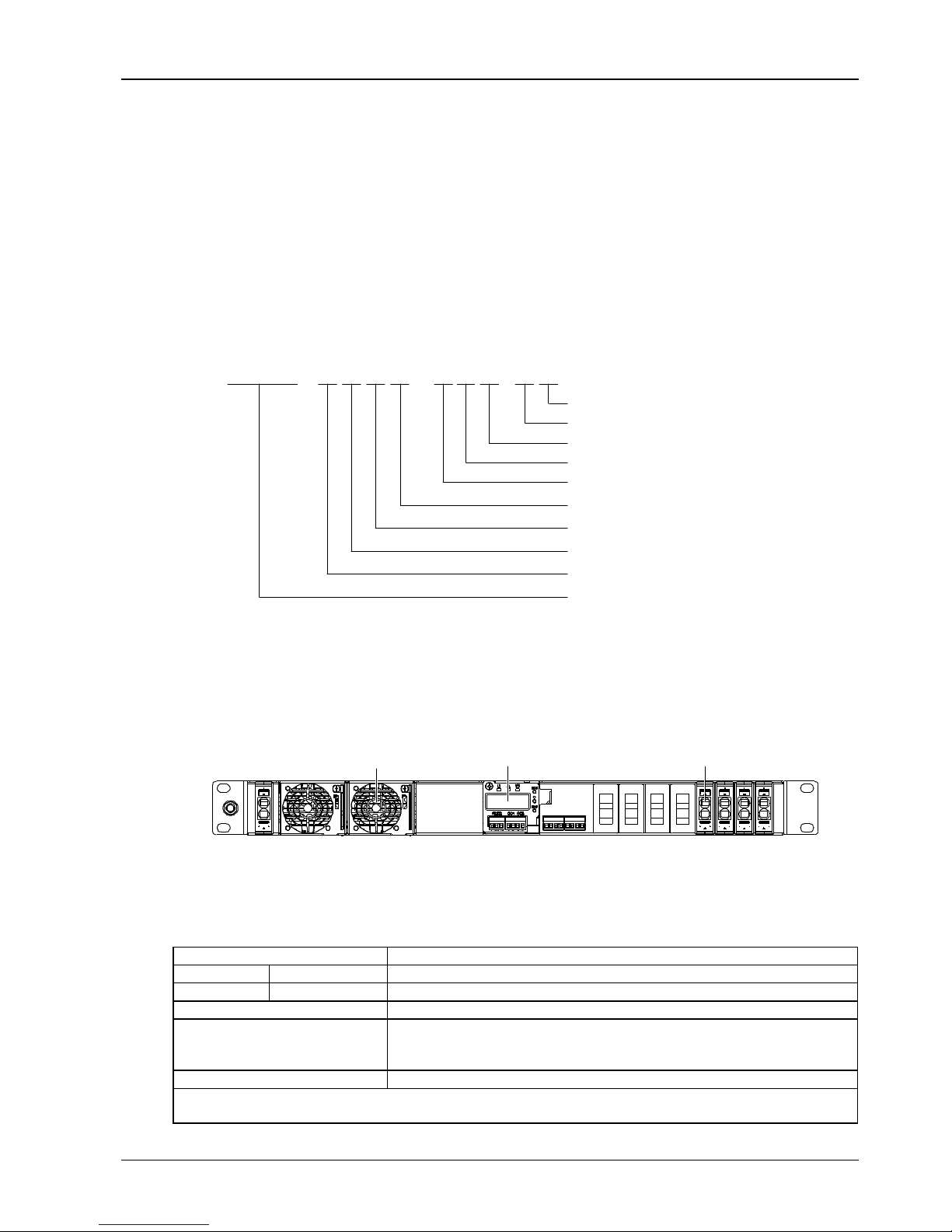
1.2 Composition And Configuration
Composition
The power system is composed of rectifiers, a controller and a power distribution unit. The structure of the power
system is shown in Figure 1-2.
Rectifier Controller Power distribution unit
Figure 1-2 Structure of the power system
Configuration
The configuration of the power system is given in Table 1-1.
Table 1-1 Configuration list
Component
Configuration
Controller
M225S
1 piece
Rectifier
R48-1000e3
Standard configuration: 2 pieces
AC distribution
L + N + PE/220Vac 1 × 30A; quick-plug terminal
DC distribution
Priority load (PL):
1 × 20A/1P; MCB 1 × 30A; quick-plug terminal
2 × 10A/1P; MCB 2 × 30A; quick-plug terminal
Battery MCB
1 × 30A/1P; MCB 1 × 30A; quick-plug terminal
Note:
Optional configuration: temperature sensor cable
2 Chapter 1 Overview
NetSure 2100 A31-S1 Subrack Power System User Manual
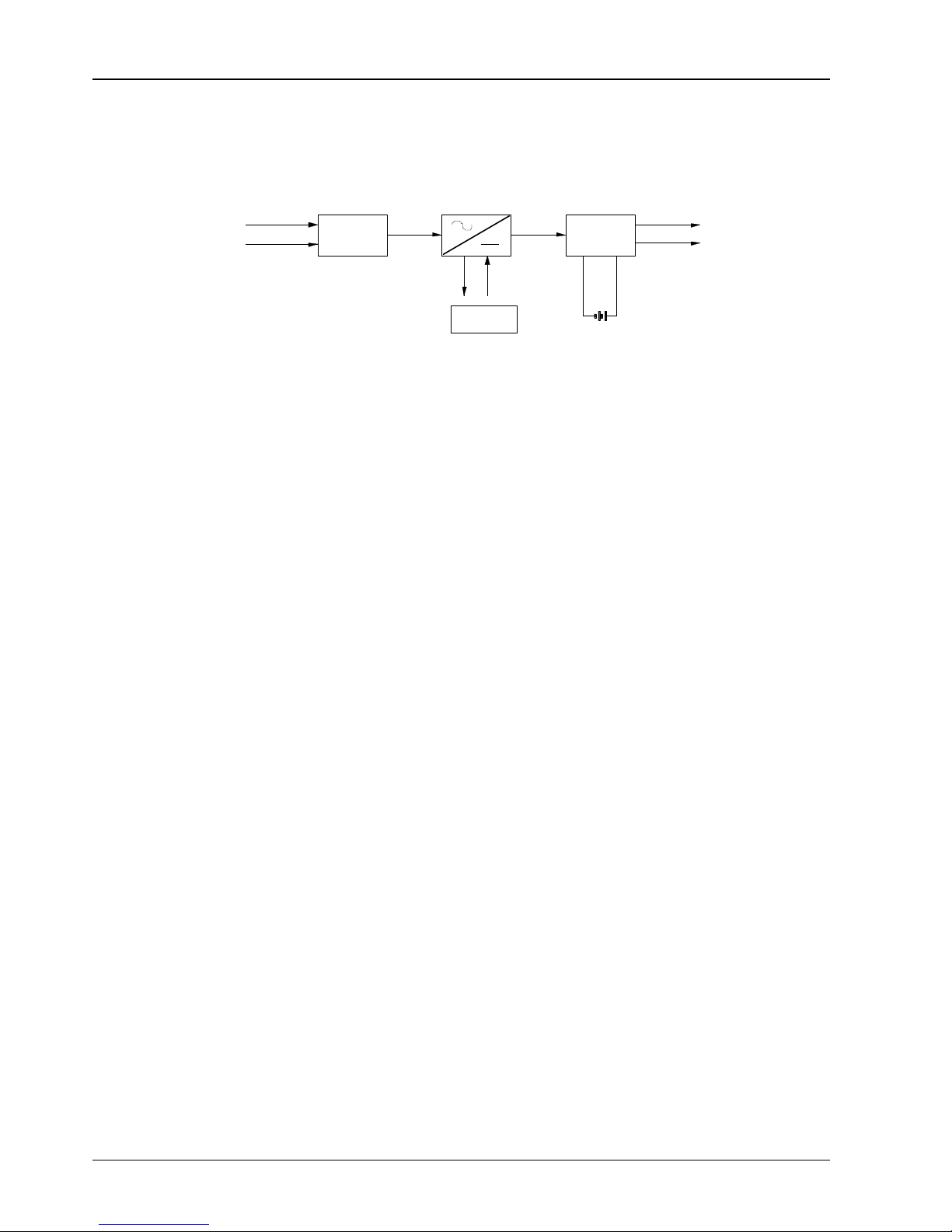
1.3 Operating Theory
Electrical theory
The schematic diagram of the power system is shown in Figure 1-3.
AC
distribution
220Vac
DC
distribution
220Vac - 48Vdc
Thermal
control unit
Rectifier
Load
Controller
Figure 1-3 Schematic diagram
The AC distribution unit introduces the AC power and feeds to the rectifier, which converts the 220Vac into -48Vdc and
delivers it to the AC distribution unit, through which the -48Vdc power is outputted to each load.
The controller has functions of battery management, LLVD, BLVD, data acquisition and alarm, and it can communicate
with the host.
Heat dissipation theory
The power system uses natural cooling to dissipate heat.
1.4 Features
Rectifier
Power factor up to 0.99, efficiency over 94.5%.
Wide AC input voltage ranges from 85Vac to 300Vac. When the input voltage is between 85Vac and 175Vac, the
rectifier will derate the output power.
High module power density.
Hot pluggable. It takes less than one minute to replace a rectifier.
Two over-voltage protection methods are optional: hardware protection and software protection. The latter one
also has two optional modes: lock out at the first over-voltage and lock out at the second over-voltage.
System
Perfect battery management. The system has BLVD function, and can perform functions such as temperature
compensation, automatic voltage regulation, stepless current limiting, battery capacity calculation, and online
battery test.
Network design. Providing multiple communication ports, which enable remote monitoring and unattended
operation.
Up to 200 pieces of historical alarm records can be recorded by M225S controller.
Complete fault protection and fault alarm functions.
Safety guideline: IP20
Application of rectifier module dormancy technology, which enhances the energy saving function of the system.
High system efficiency: above 93.5%.

Chapter 2 Installation 3
NetSure 2100 A31-S1 Subrack Power System User Manual
Chapter 2 Installation
This chapter introduces the installation and cable connection of the power system. Before installation, please read
through the safety regulations, and then follow the instructions in this chapter to carry out the installation and cable
connection.
2.1 Safety Regulations
Certain components in the power system carry hazardous voltage and current. Always follow the instructions below:
1. Only trained personnel with adequate knowledge of the power system shall carry out the installation. The Safety
Precautions listed before the Contents of this manual and local safety rules in force shall be adhered to during the
installation.
2. All external circuits below -48V connected to the power system must comply with the SELV requirements defined in
IEC 60950.
3. Do not operate or maintain the power system under thunderstorm or humid weather!
4. Make sure that the power system is powered off before any operation carried out within the system.
5. The power cables should be routed and protected properly, so that the cables are kept away from the operation and
maintenance personnel.
2.2 Preparation
Unpacking inspection
The equipment should be unpacked and inspected after it arrives at the installation site. The inspection shall be done
by representatives of both the user and Vertiv Tech Co., Ltd..
To inspect the equipment, you should open the packing case, take out the packing list and check against the packing
list that the equipment is correct and complete. Make sure that the equipment is delivered intact.
Note
The rectifiers have been installed in the subrack power system at factory.
Preparing cables
The cable should be selected in accordance with relevant electric industry standards.
It is recommended to use the RVVZ cables as AC cables. The cables should reach at least +70°C temperature
durability.
Select the AC cable CSA according to Table 2-1.
Table 2-1 Selection of AC cable CSA
Connector
Specification
AC cable CSA
AC input terminal
1 × 30A quick-plug terminal
≤ 10mm2
Note: With cable shorter than 30m, the CSA calculation should be based on the current density of 2.5A/mm2. The recommended
CSA value is not less than 2.5mm2
The DC cable CSA depends on the current flowing through the cable, the allowable voltage drop and the load peak
capacity. The recommended load peak capacity is 1/2 to 2/3 of MCB capacity.
 Loading...