

Vertiv Tech NetSure 731 C62 Series, NetSure 731 C62-X2, NetSure 731 C62-X1, NetSure 731 CC2-X4, NetSure 731 C62-X3 User Manual
...Page 1

NetSure 731 CC2、NetSure 731
C62 系列电源系统
用户手册
NetSure 731 CC2, NetSure 731 C62
Series Power Supply System
User Manual
资料版本 V2.0
归档时间 2017-12-31
BOM 编码 31013521
Version V2.0
Revision date December 31, 2017
BOM 31013521
维谛技术有限公司为客户提供全方位的技术
支持,用户可与就近的维谛技术有限公司办事
处或客户服务中心联系,也可直接与公司总部
联系。
维谛技术有限公司
版权所有,保留一切权利。内容如有改动,恕
不另行通知。
维谛技术有限公司
地址:深圳市南山区学苑大道 1001 号南山智
园 B2 栋
邮编:518055
公司网址:www.vertivco.com
客户服务热线:4008876510
E-mail: [email protected]
Vertiv Tech provides customers with technical
support. Users may contact the nearest Vertiv local
sales office or service center.
Copyright © 2017 by Vertiv Tech Co., Ltd.
All rights reserved. The contents in this document
are subject to change without notice.
Vertiv Tech Co., Ltd.
Address: Block B2, Nanshan I Park, No.1001
Xueyuan Road, Nanshan District, Shenzhen,
518055, P.R.China
Homepage: www.vertivco.com
E-mail: [email protected]
Page 2

Declaration
This is a Class A UPS product. In a residential environment, this product may nevertheless cause radio
interference, in which case, the user is required to take additional measures to reduce the interference.
Safety Precautions
To reduce the chance of accident, please read the safety precautions very carefully before operation. The
'Caution, Note, Warning, Danger' in this book and on the product do not represent all the safety points to be
observed, and are only supplement to various safety points. Therefore, the installation and operation personnel
must receive strict training and master the correct operations and all the safety points before operation.
When operating Vertiv products, the operation personnel must observe the safety rules in the industry, the
general safety points and special safety instructions provided by Vertiv.
Electrical Safety
I. Hazardous voltage
Danger
Danger
Some components of the power system carry hazardous voltage in operation. Direct contact or
indirect contact through moist objects with these components will result in fatal injury.
Observe safety rules in the industry when installing the power system. The installation personnel must be
licensed to operate high voltage and AC power.
In operation, the installation personnel are not allowed to wear conductive objects, such as watches, bracelets,
bangles and rings.
When you spot the cabinet with water or moisture, turn off the power immediately. In moist environment,
precautions must be taken to keep moisture out of the power system.
’Prohibit’ warning label m ust be attached to the switches and buttons that are not permi tted to operate during
installation.
Danger
Danger
High voltage operation may cause fire and electric shock. The connection and w iring of AC cables
must be in compliance with the local rules and regulations. Only those who are licensed to operate
high voltage and AC power can perform high voltage operations.
II. Tools
Warning
In high voltage and AC operation, specialized tools must be used.
III. Thunderstorm
Danger
Danger
Never operate on high voltage, AC, iron tower or mast in the thunderstorm.
In thunderstorms, a strong electromagnetic field will be generated in the air. Therefore the equipment should be
well earthed in time to avoid damage by lightning strikes.
IV. ESD
Note
The static electricity generated by the human body will damage the static sensitive elements on PCBs,
such as large-scale ICs. Before touching any plug-in board, PCB or IC chip, ESD w rist strap must be
worn to prevent body static from damaging the sensitive components. The other end of the ESD w rist
strap must be w ell earthed.
Page 3
V. Short circuit
Danger
Danger
During operation, never short the positive and negative poles of the DC distribution unit of the
power system or the non-grounding pole and the earth. The power system is a constant-voltage
DC power device, short circuit will result in equipment burning and endanger human safety.
Check the polarity of the cable and connection terminal when performing DC live operations.
As the operation space in the DC distribution unit is very tight, please carefully select the operation space.
Never wear a watch, bracelet, bangle, ring, or other conductive objects during operation.
Use insulated tools.
In live operation, keep the arm, wrist and hand tense, so that when the tool in operation slips, the movement of
the human body and tool is reduced to a minimum.
Battery
Danger
Danger
Before any operation on battery, read carefully the safety precautions for battery transportation and
the correct battery connection method.
Note
If the power system does not connect with mains power for a long time, to prevent battery
over-discharge, users should cut batteries off from the pow er system thoroughly, for example, pulling
out battery fuses or switching off battery MCBs. Before putting the power system into operation, insert
all the battery fuses or switch on all the battery MCBs.
Non-standard operation on the battery will cause danger. In operation, precautions should be taken to prevent
battery short circuit and overflow of electrolyte. The overflow of electrolyte will erode the metal objects and PCBs,
thus causing equipment damage and short circuit of PCBs.
Before any operation on battery, pay attention to the following points:
1. Remove the watch, bracelet, bangle, ring, and other metal objects on the wrist.
2. Use specialized insulated tools.
3. Use eye protection device, and take preventive measures.
4. Wear rubber gloves and apron to guard against electrolyte overflow.
5. In battery transportation, the electrode of the battery should always be kept facing upward. Never put the
battery upside down or slanted.
LLVD And BLVD
The power system has battery low voltage disconnection (BLVD) function and load low voltage disconnection
(LLVD) function. LLVD means that the mains fail and batteries supply power, the controller cuts the non-priority
load off when the battery voltage drops down to below 44V. In this way, the battery remaining capacity can
sustain the priority load longer. BLVD means that the controller cuts the load off when the battery voltage drops
down to 43.2V to prevent over-discharge.
The factory setting is enabling LLVD and BLVD, which means that if power outage lasts for a long time or the
power system fails, there might be LLVD and BLVD. Users should classify the loads and connect the nonpriority loads to LLVD routes, and connect the priority loads to BLVD routes. For vital loads, users can disable
BLVD of these loads to insure reliability of the power supply.
The method of disabling BLVD is:
1. Hardware disabling: unplug the signal cable in J10 interface of the controller. Tag the BLVD-disabled label.
The position of the controller and the interface description are given in 2.4.2 Connecting Signal Cables.
2. Software disabling: set ‘BLVD Enable’ item of the controller to ‘N’.
Page 4
Note
The advantage of enabling BLVD is protecting the batteries from over-discharge when the battery
voltage is low. The disadvantage of enabling BLVD is that when the battery voltage drops down to a
certain value, all the loads (including non-priority loads and priority loads) will be cut off due to battery
disconnection.
The advantage of software disabling BLVD is prolonging the power supply of priority loads. The
disadvantage is that software disabling cannot prevent unwanted power failure due to misoperation or
power system failure.
The advantage of hardware disabling BLVD is preventing unwanted power failure due to misoperation
or power system failure, and ensuring the continuity of vital loads’ power supply.
Others
I. Sharp object
Warning
When moving equipment by hand, wear protective gloves to avoid injury by sharp object.
II. Power cable
Note
Please verify the cable labels before connection.
III. Signal cables
Note
The signal cables should be routed at least 150mm aw ay from power cables.
Note
Note
To preserve the environment, the busbar of the power system may use tinning technique or
passivation technique. The busbar may become dark due to long-term operation, w hich does not
influence the performance or use of the power system.
Page 5

Contents
Chapter 1 Overview ................................................................................................................................................................................1
1.1 Model Description ...................................................................................................................................................................1
1.2 Composition And Configuration ............................................................................................................................................1
1.3 Features....................................................................................................................................................................................6
1.4 Operating Principle .................................................................................................................................................................6
1.5 Functions ..................................................................................................................................................................................6
1.5.1 Lightning And Surge Protection ...............................................................................................................................6
1.5.2 LLVD And BLVD .........................................................................................................................................................8
1.5.3 Fault Alarm And Protection .......................................................................................................................................8
1.5.4 AC And DC Distribution .............................................................................................................................................8
1.5.5 Earthing Design ..........................................................................................................................................................9
Chapter 2 Installation Instruction ....................................................................................................................................................... 10
2.1 Safety Regulations............................................................................................................................................................... 10
2.2 Preparation............................................................................................................................................................................ 10
2.3 Mechanical Installation ........................................................................................................................................................ 11
2.3.1 Installing Power Cabinet......................................................................................................................................... 11
2.3.2 Installing Rectifiers .................................................................................................................................................. 12
2.4 Electrical Installation ............................................................................................................................................................ 12
2.4.1 Connecting Power Cables ..................................................................................................................................... 12
2.4.2 Connecting Signal Cables...................................................................................................................................... 14
2.4.3 Bottom Cabling Cabinet ......................................................................................................................................... 17
Chapter 3 Testing................................................................................................................................................................................. 19
3.1 Installation Check And Startup .......................................................................................................................................... 19
3.2 Basic Settings ....................................................................................................................................................................... 20
3.3 Alarm Check And System Operation Status Check ....................................................................................................... 20
3.4 Final Steps ............................................................................................................................................................................ 21
Chapter 4 Use Of The Controller....................................................................................................................................................... 22
4.1 Operation Panel ................................................................................................................................................................... 22
4.2 Main LCD Screens............................................................................................................................................................... 22
4.2.1 System Information Screen ................................................................................................................................... 22
4.2.2 Password Confirmation Screen............................................................................................................................. 23
4.2.3 MAINMENU Screen ................................................................................................................................................ 23
4.2.4 STATUS Screen ...................................................................................................................................................... 24
4.2.5 Settings Screen ....................................................................................................................................................... 24
4.2.6 Maintenance Screen ............................................................................................................................................... 24
4.2.7 Energy Saving Screen ............................................................................................................................................ 25
4.2.8 Fast Settings Screen............................................................................................................................................... 25
Page 6

4.3 Querying System Main Information................................................................................................................................... 25
4.4 Querying Rectifier Status .................................................................................................................................................... 27
4.5 Querying Alarm Information ............................................................................................................................................... 27
4.5.1 Querying Active Alarm ............................................................................................................................................ 27
4.5.2 Querying History Alarm .......................................................................................................................................... 29
4.6 Maintenance ......................................................................................................................................................................... 29
4.7 Setting Parameters .............................................................................................................................................................. 30
4.7.1 Alarm Settings.......................................................................................................................................................... 30
4.7.2 Battery Settings ....................................................................................................................................................... 32
4.7.3 AC Settings............................................................................................................................................................... 37
4.7.4 DC Settings .............................................................................................................................................................. 37
4.7.5 Rectifier Settings ..................................................................................................................................................... 38
4.7.6 System Settings....................................................................................................................................................... 39
4.7.7 Communication Settings ........................................................................................................................................ 39
4.8 Energy Saving Settings....................................................................................................................................................... 40
4.9 Fast Settings ......................................................................................................................................................................... 41
Chapter 5 Technical Parameters of Rectifier .................................................................................................................................. 42
5.1 Appearance and Structure.................................................................................................................................................. 42
5.2 Functions And Features ...................................................................................................................................................... 43
5.3 Technical Parameters ......................................................................................................................................................... 46
Chapter 6 Troubleshooting ................................................................................................................................................................. 48
6.1 Handling Alarms ................................................................................................................................................................... 48
6.2 Handling Rectifier Fault....................................................................................................................................................... 49
6.3 Handling Controller Fault .................................................................................................................................................... 51
Appendix 1 Technical Data................................................................................................................................................................. 54
Appendix 2 Engineering Diagram...................................................................................................................................................... 57
Appendix 3 Parameter Setting Of The Controller ........................................................................................................................... 61
Appendix 4 Menu Structure Of The Controller ................................................................................................................................ 65
Appendix 5 Schematic Diagram ........................................................................................................................................................ 67
Appendix 6 Wiring Diagram................................................................................................................................................................ 69
Page 7
Chapter 1 Overview 1
NetSure 731 CC2, NetSure 731 C62 Series Power Supply System User Manual
Chapter 1 Overview
This chapter introduces the model description, composition and configuration, features, operating principle and
functions of the NetSure 731 CC2 and NetSure 731 C62 series power system (power system for short).
1.1 Model Description
Taking NetSure 731 CC2 power system as an example, the model description is given in Figure1-1.
Power system brand
Rectifier specification: G3 50A
Region: China
Max number of the rectifier: 12
Cabinet configuration type
System version: 2
NetSure
731
C
C
2
-
X1
Figure 1-1 Model description
1.2 Composition And Configuration
Composition
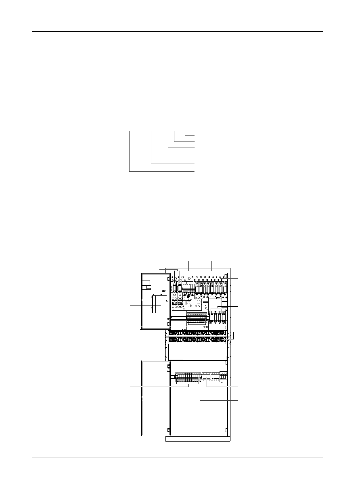
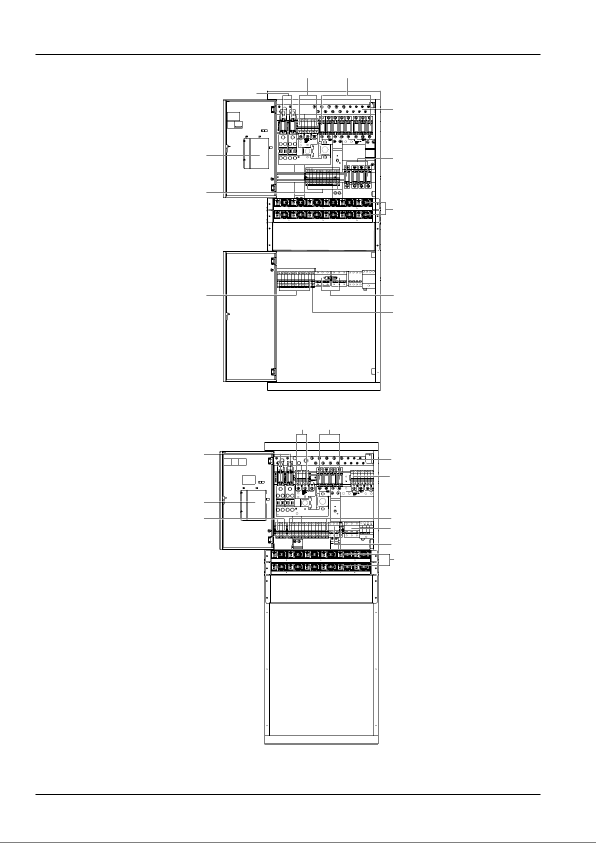
The NetSure 731 CC2 power system has four models: NetSure 731 CC2-X1, NetSure 731 CC2-X2, NetSure 731
CC2-X3 and NetSure 731 CC2-X4. Figure 1-2 to Figure 1-5 illustrate the structure of the four models. NetSure 731
C62 has three models: NetSure 731 C62-X1, NetSure 731 C62-X2 and NetSure 731 C62-X3, the structure of this
model are shown in Figure 1-6 and Figure1-8.
Battery fuse
Priority load MCB Non- priority load fuse
DC output positive busbar
Rectifier
AC input MCB
controller
Non- priority load MCB
Rectifier MCB
Non- priority load fuse
AC output MCB
Figure 1-2 NetSure 731 CC2-X1 power system structure
Page 8
2 Chapter 1 Overview
NetSure 731 CC2, NetSure 731 C62 Series Power Supply System User Manual
Priority load MCB Non- priority load fuse
Battery fuse
controller
Non- priority load MCB
Rectifier MCB
DC output positive busbar
Rectifier
AC input MCB
Non- priority load fuse
AC output MCB
Figure 1-3 NetSure 731 CC2-X2 power system structure
Battery fuse
Controller
Priority load MCB
Non-priority load fuse
Non-priority load MCB
Rectifier
Rectifier MCB
AC output MCB
AC input MCB
DC output positive busbar
Non-priority load MCB
Figure 1-4 NetSure 731 CC2-X3 power system structure
Page 9

Chapter 1 Overview 3
NetSure 731 CC2, NetSure 731 C62 Series Power Supply System User Manual
Battery fuse
Controller
Priority load MCB
Non-priority load fuse
DC output positive busbar
Non-priority load MCB
Rectifier
Non-priority load MCB Rectifier MCB
AC output MCB
AC input MCB
Figure 1-5 NetSure 731 CC2-X4 power system structure
Priority load MCB Non- priority load fuse
Battery fuse
DC output positive busbar
Controller
Non- priority load MCB
Rectifier MCB
Rectifier
AC input MCB
AC output MCB
Figure 1-6 NetSure 731 C62-X1 power system structure
Page 10

4 Chapter 1 Overview
NetSure 731 CC2, NetSure 731 C62 Series Power Supply System User Manual
Battery fuse
Priority load MCB Non- priority load fuse
DC output positive busbar
Controller
Non- priority load MCB
Rectifier MCB
AC input MCB
Rectifier
AC output MCB
Figure 1-7 NetSure 731 C62-X2 power system structure
Priority load MCB
Battery fuse
controller
Non- priority load MCB
DC output positive busbar
AC input MCB
Non- priority load fuse
AC output MCB
Module MCB
Rectifier MCB
Figure 1-8 NetSure 731 C62-X3 power system structure
Page 11
Chapter 1 Overview 5
NetSure 731 CC2, NetSure 731 C62 Series Power Supply System User Manual
Configuration
(1) The configuration of the power system is listed in Table 1-1.
Table 1-1 Power system configuration
Component
Configuration
NetSure 731 C62
NetSure 731 CC2
Rectifier
Model: R48-3000e3
Standard: 6 pcs
Optional: 2 ~ 6 pcs
Model: R48-3000e3
Standard: 12 pcs
Optional: 2 ~ 12 pcs
Controller
Model: M522S; Standard: 1 pcs
Model: M522S; Standard: 1 pcs
AC distribution
AC input:
NetSure 731 C62-X1, X2, X3: 1 × 63A/3P MCB
AC input:
NetSure 731 CC2-X1, X3, X4: 1 × 100A/3P MCB
NetSure 731 CC2-X2: 2 × 100A/3P MCB
AC output:
NetSure 731 C62-X1, X2: 1 × 16A/1P MCB
NetSure 731 C62-X3: 1 × 16A/1P MCB, 1 ×
16A/3P MCB
AC output:
NetSure 731 CC2- X1, X2: 1 × 16A/1P MCB
NetSure 731 CC2- X3, X4: 1 × 16A/3P MCB,
1 × 16A/1P MCB
DC ditribution
Priority load output:
NetSure 731 C62-X1: 2 × 32A/1P MCB,
2 × 10A/1P MCB
NetSure 731 C62-X2: 2 × 32A/1P MCB,
2 × 10A/1P MCB
NetSure 731 C62-X3: 2 × 32A/1P MCB,
2 × 16A/1P MCB
Priority load output:
NetSure 731 CC2-X1/X2: 2 × 32A/1P MCB, 4 × 10A/1P
MCB
NetSure 731 CC2-X3: 4 × 16A/1P MCB
NetSure 731 CC2-X4: 2 × 63A/1P MCB, 2 × 32A/1P
MCB,
2 × 10A/1P MCB
Non-priority load output:
NetSure 731 C62-X1:
4 × 100A fuse, 4 × 63A/1P fuse,
4 × 32A/1P MCB,
2 × 10A/1P MCB
NetSure 731 C62-X2:
4 × 100A fuse, 4 × 63A fuse,
4 × 32A/1P MCB,
2 × 10A/1P MCB
NetSure 731 C62-X3:
4 × 100A fuse,
4 × 63A/1P MCB,
6 × 32A/1P MCB
Non-priority load output:
NetSure 731 CC2-X1/X2:
6 × 100A fuse, 6 × 63A fuse, 6 × 32A/1P MCB,
4 × 16A/1P MCB
NetSure 731 CC2-X3:
4 × 100A fuse, 4 × 63A/1P MCB, 6 × 32A/1P MCB
NetSure 731 CC2-X4:
4 × 100A fuse, 6 × 63A fuse, 2 × 32A/1P MCB,
2 × 16A/1P MCB
Battery branch circuit:
NetSure 731 C62-X1: 2 × 250A fuse
NetSure 731 C62-X2: 2 × 250A fuse
NetSure 731 C62-X3: 2 × 250A fuse
Battery branch circuit:
2 × 500A fuse
Optional parts
Top cover, temperature sensor and modem, front and back cover plate (NetSure 731 C62-X2), Battery cable
(NetSure 731 C62-X2)
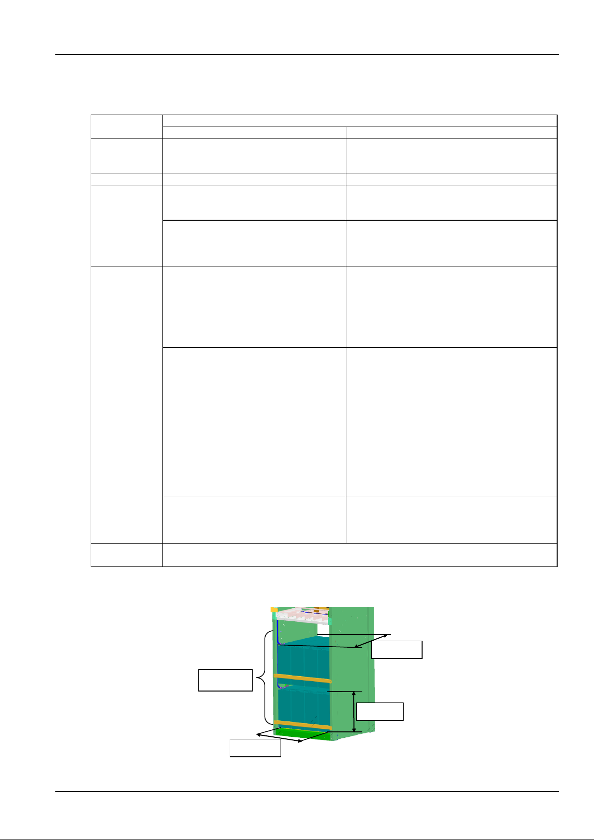
(2) NetSure 731 C62-X2 power system is configured with two layers of battery rack, the battery compartment space is
shown in Figure 1-9.
Figure 1-9 Battery compartment structure
330mm
570mm
535mm
Tw o layers
Page 12

6 Chapter 1 Overview
NetSure 731 CC2, NetSure 731 C62 Series Power Supply System User Manual
1.3 Features
The rectifier uses the active Power Factor Compensation (PFC) technology, raising the power factor to 0.99
The power supply system has wide AC input voltage range: 90Vac ~ 300Vac
The rectifier uses soft switching technology, raising the efficiency up to 95%
The rectifier is of High power density
The rectifier is hot pluggable. It takes less than 1min to replace a rectifier
The rectifier has two optional over-voltage protection methods: hardware protection and software protection. The
latter one also has two optional modes: lock-out at the first over-voltage and lock-out at the second over-voltage
The power system has perfect battery management function. The management functions include BLVD, LLVD,
temperature compensation, auto voltage regulation, stepless current limiting, battery capacity calculation and
on-line battery test, etc
The power system can save up to 200 pieces of historical alarm records, and 10 sets of battery test data records
The power system is of network design. Providing multiple communication ports (such as RS232, modem and
dry contacts), which enables flexible networking, remote monitoring and unmanning
The power supply system has perfect lightning protection at both AC side and DC side
The power supply system has complete fault protection and fault alarm functions
1.4 Operating Principle
The AC mains comes out from the AC distribution unit and is distributed to each rectifier. After rectification, the -48V
DC current from each rectifier flows to the DC distribution unit through busbar, and then multiple outputs of the DC
distribution unit provide power for communication equipment. Normally, the system operates in parallel float charge
state, that is, the rectifiers, load and batteries work in parallel; besides powering the communication equipment, the
rectifiers provide float charge for the batteries. In case of mains failure, the rectifiers will stop working, and the
batteries begin to supply power to communication equipment. When the AC mains recovers, the rectifiers will resume
supplying power to communication equipment and charging the batteries.
Using centralized monitoring mode, the controller module manages the AC distribution unit and DC distribution unit. It
also receives the operating data of the rectifiers and controls them accordingly through CAN mode. The controller can
be connected to a local computer using the RS232 port. The power system can be connected to the monitoring
center through connecting a modem or other transmission resources (such as PSTN and so on) to achieve remote
monitoring.
For the detailed schematic diagram of the power system, see Appendix 5 Schematic Diagram.
1.5 Functions
Main functions of the power system include:
Lightning and surge protection.
LLVD and BLVD.
Fault alarm and protection.
AC and DC distribution.
Perfect earthing design.
1.5.1 Lightning And Surge Protection
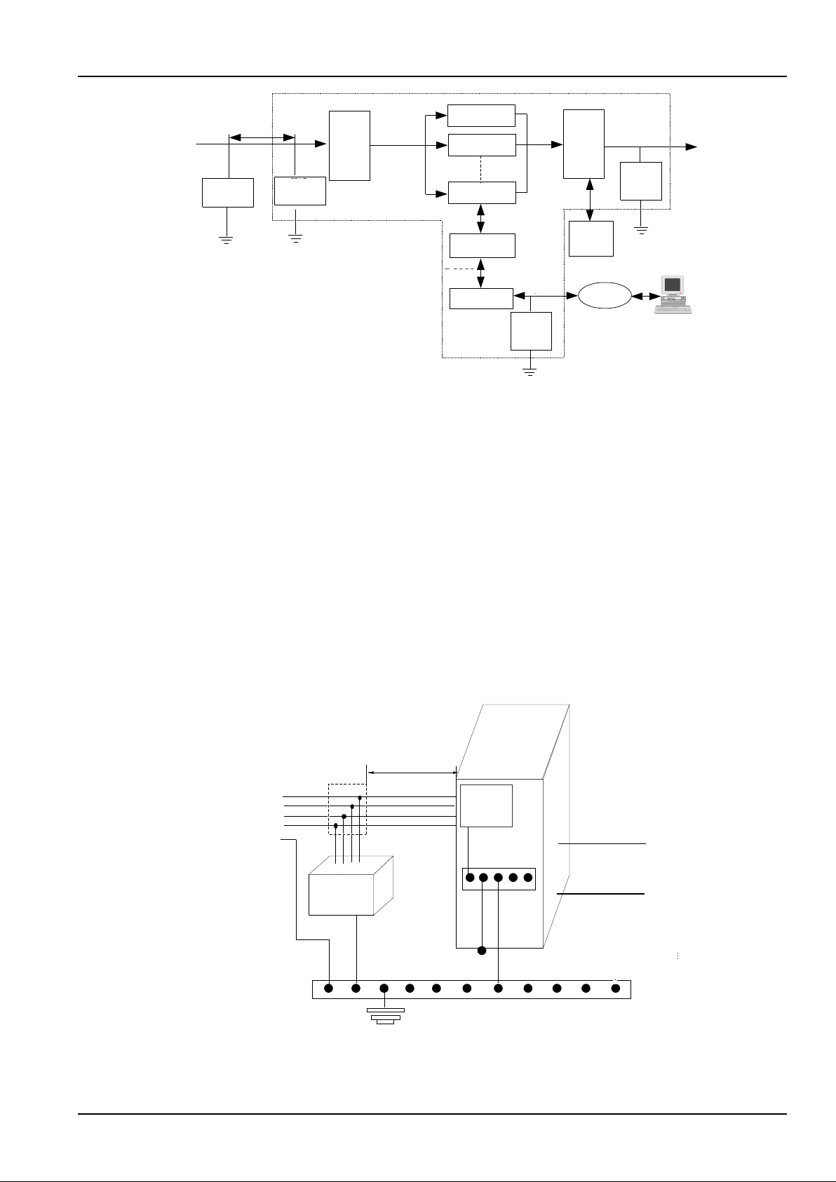
The power system is equipped with lightning protection at both the AC side and the DC side. The lightning protection
system is shown in Figure 1-10.
Page 13
Chapter 1 Overview 7
NetSure 731 CC2, NetSure 731 C62 Series Power Supply System User Manual
交流输入
整流模块
整流模块
整流模块
交流
配电
单元
直流
配电
单元
监控模块
电池组
1、2
I/B
防雷器
DC
防雷器
Modem
RJ11
防雷器
-48V输出
RS232
RJ11
5m~10m
PSTN
远程后台监控
注:I,II,III级是IEC标准的分类方法
B,C,D级是德国VDE标准的分类方法
II/C
防雷器
AC input
5m ~ 10m
I/B SPD
II/C SPD
AC
distribution
unit
Rectifier
Rectifier
Rectifier
Controller
RS232
Modem
RJ11
RJ11
SPD
DC
distributi
on unit
DC
SPD
Battery
string
1, 2
PSTN
Remote host
- 48V output
Note:Classes I,II,III are IEC atandard,
classes B, C, D are VDE Geman standards.
Figure 1-10 Lightning protection system
The power system is equipped with a Class II/C SPD. Meanwhile, each module of the system has perfect lightning
protection circuit. The system can withstand simulated lightning surge currents of 20kA at 8/20μs five times, and
40kA at 8/20μs once. To prevent higher lightning strikes from damaging the equipment, it is recommended to install a
higher protective Class I/B SPD in the cable inlet of the equipment room (lightning surge current is at least 60kA, refer
to YD/T5098-2001 Signal station lightning overvoltage protection engineering design standard).
To prevent lightning strikes at the DC side from damaging the equipment, an effective lightning protection device is
provided, which can withstand simulated lightning surge currents of 10kA and 15kA at 8/20μs once respectively. To
prevent conductive lightning strike from damaging the modem port of the controller, the power system provides
lightning protection (optional) for the modem port. The SPD can withstand a 5kA lightning surge current at 8/20s and
a 4kV lightning surge voltage at 10/700s.
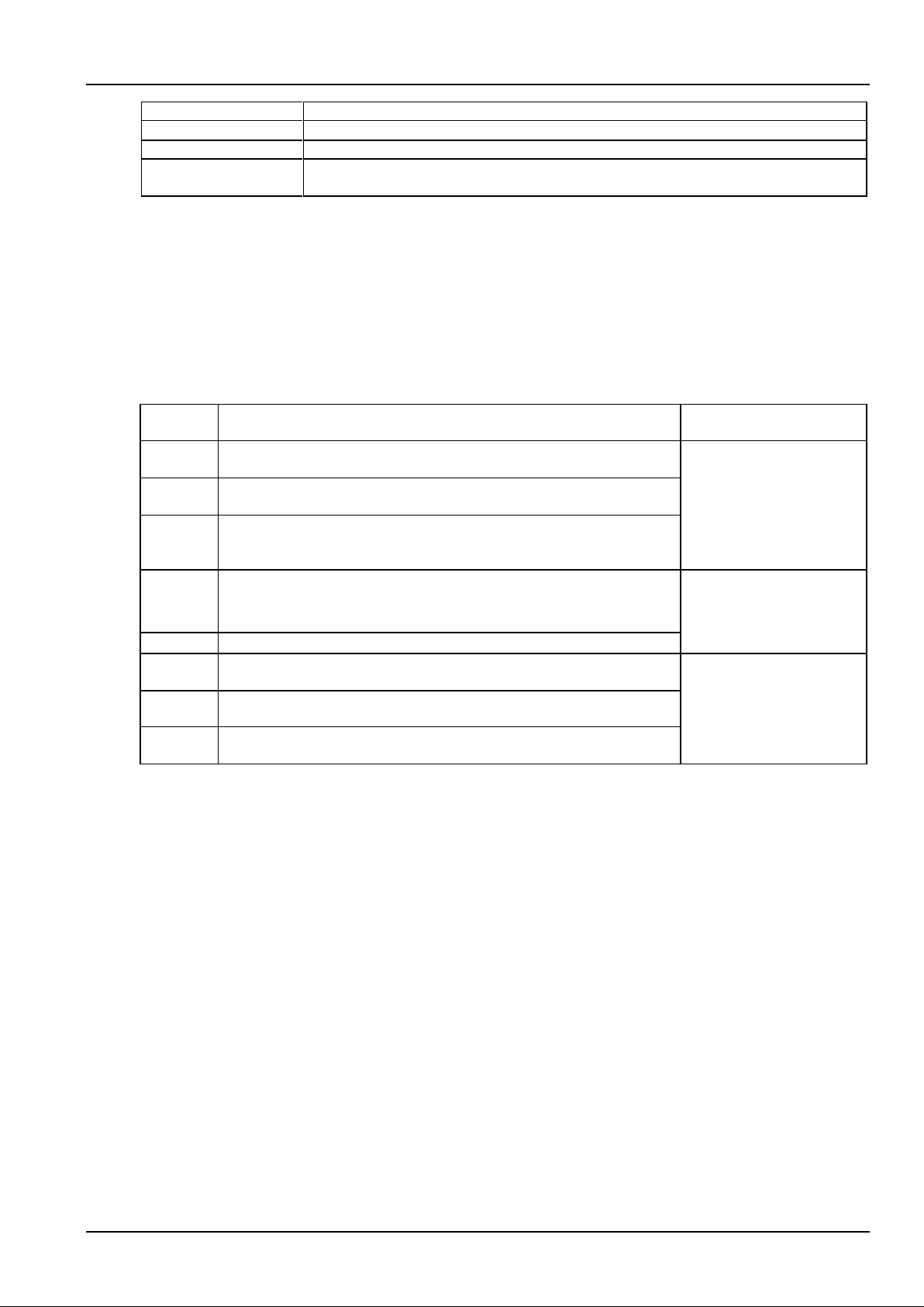
The power system has perfect lighting protection at both AC side and DC side. The power system is equipped with a
Class II/C SPD at AC side and SPD at DC side. To achieve better lightning protection at AC side, it is recommended
to mount a Class I/B SPD, lightning surge current is at least 60kA. The Class I/B SPD should be purchased by the
user. Refer to YD/T5098-2001 Signal station lightning overvoltage protection engineering design standard for the
detailed technical rules. The Class I/B SPD installation is shown in Figure 1-11.
48Vdc
+
-
A
B
C
N
PE
5m ~ 10m
Class-B
SPD
SPD
DC earth
Protective earth cable
User earth bar
System earth bar
Protective earth
Power supply
system
SPD earth
SPD earth
DC earth cable
240Vdc
Class-C
SPD
240Vdc
First
Class-B
SPD
Power system
-48Vdc
+
-
lever 1 SPD
(Class B)
Lever
Class
Lever 1
(Class B)
SPD
Lever 2
(Class C)
SPD
Level 1
Level 2
Figure 1-11 Diagram of Class I/B SPD mounting & system earthing
The Class I/B SPD should be purchased and mounted by the user. If condition permits, it is recommended that the
cable length between the Class I/B SPD and the power system meet the following rules: if a voltage limiting type SPD
Page 14

8 Chapter 1 Overview
NetSure 731 CC2, NetSure 731 C62 Series Power Supply System User Manual
is used, then the cable length should be longer or equal than 5m; if a switching type SPD is used, then the cable
length should be longer or equal than 10m. The cable between the Class I/B SPD and the input terminals of the AC
distribution unit of the power system should be routed indoors to avoid direct lightning strike. The output cable CSA of
the Class I/B SPD and the grounding cable CSA should not be less than 16mm2. For the cable length, the shorter the
better.
The power system has lighting protection at DC side, which can meet YD/T5098 requirements. There’s no need to
design lighting protection at DC side.
1.5.2 LLVD And BLVD
In case of mains failure, the rectifiers will stop working and the batteries will begin to discharge and power the load.
When the battery voltage falls to the low voltage alarm point 45.0V (adjustable), the system will give audible/visual
alarm. When the battery voltage continues to fall and reaches the LLVD point 44.0V (adjustable), the LLVD contactor
will open, cutting off the power supply for the non-priority loads connected to the LLVD output branches thus the
power supply to priority load can be prolonged. As the batteries discharge, the battery voltage continues to fall. When
it reaches the BLVD point 43.2V (adjustable), the BLVD contactor will open, and the battery discharge will come to an
end. Thus the power supply to all loads is stopped, protecting the battery from being damaged due to over-discharge.
When the mains recovers and the rectifier output resumes normal functioning, the LLVD and BLVD contactors will
automatically close, and the system will resume normal operation.
1.5.3 Fault Alarm And Protection
The power system provides perfect fault alarm and protection functions. The system operating data can be collected
and the states of the load MCBs, load fuses, battery fuses and Level 2 (class C) SPD can be detected by the
controller. The alarm level can be set and audible/visual alarms can be selected for the system alarms, such as AC
input over/under voltage, DC output over/under voltage, fuse alarm, float charge and equalized charge status, rectifier
fault and protection alarm. The alarm type can be configured to correspond to dry contact relay output.
1.5.4 AC And DC Distribution
The functions of AC distribution are as follows:
The AC input uses 3-pole MCB, and has short circuit and over-current protection.
The AC input has overvoltage and undervoltage protection.
See Table 1-2 for the functions of the AC input and output interfaces of the power system.
Table 1-2 Functions of AC input and output interfaces
Interface
Functions
AC input MCB
To AC power supply; switchable
AC output MCB
Provides phase line terminal of AC; used to power other AC equipment
AC input neutral line busbar
To the neutral line of the 3-phase AC input
Earth terminal
The junctions of the protection earth, SPD earth, operation earth of the power system; need
connect to the earth bar of the equipment room
The functions of DC distribution are as follows:
Output load branch has short circuit and over-current protections, and branch capacity can be adjusted
according to user requirements.
Battery input uses fuse which has functions like short circuit, over-current protection, alarm and fault status
detection.
Battery current detection.
DC output overvoltage, undervoltage alarm functions.
See Table 1-3 for the functions of the DC input and output interfaces of the power system.
Table 1-3 Functions of DC input and output interface functions
Interface
Functions
Battery 1 fuse
To negative terminal of the battery string 1
Page 15
Chapter 1 Overview 9
NetSure 731 CC2, NetSure 731 C62 Series Power Supply System User Manual
Interface
Functions
Battery 2 fuse
To negative terminal of the battery string 2
DC output positive busbar
To positive terminal of battery string 1 and 2, and load output positive terminal
Priority load MCB
Negative terminal of 48V supply for priority load. Cut off the priority load output when the battery
voltage drops to the BLVD point
1.5.5 Earthing Design
Protective earth, SPD earth, and DC operation earth of the power system have been connected to the earth bar
before it is delivered. During the installation, user should connect the grounding terminal to the user earth bar of the
equipment room, as shown in Figure 1-11.
The protective earth cable of 3-phase 5-line system can be directly connected to the earth bar of the equipment room.
The earth resistance should be in accordance with the specifications listed in Table 1-4.
Table 1-4 Earth resistance requirements for communication station
Earth
resistance
Application range
Basis
< 1Ω
Integrated building, international telecom bureau, tandem station, SPC sw itching
office above 10000 lines, toll office above 2000 lines
YDJ20-88 Provisional
technical regulations of
computerized telephone
sw itching equipment
installation and design
< 3Ω
SPC switching office above 2000 lines and below 10000 lines, toll office below
2000 routes
< 5Ω
SPC switching office with less than 2000 lines, optical cable terminal station,
carrier w ave repeating station, earth station, microwave junction center, mobile
communication machine station
< 10Ω
Microwave relay station, optical cable relay station, small-sized earth station
YD2011-93 Microwave station
lightning protection and
grounding design
specifications
< 20Ω
Microwave passive relay station
< 10Ω
Suitable for those w hose earth resistance rate is less than 100Ω·m, SPD earth in
the interface between electric cable and aerial electric line
GBJ64-83 Industrial and civil
electrical device overvoltage
protection design specification
< 15Ω
Suitable for those whose earth resistance rate is 100-500Ω·m, SPD earth in the
interface between electric cable and aerial electric line
< 20Ω
Suitable for those whose earth resistance rate is 501-1000Ω·m, SPD earth in the
interface between electric cable and aerial electric line
Page 16

10 Chapter 2 Installation Instruction
NetSure 731 CC2, NetSure 731 C62 Series Power Supply System User Manual
Chapter 2 Installation Instruction
This chapter introduces installation and cable connection. Before installation, please read through the safety
regulations, and then follow the instructions in this chapter to carry out the installation and connection.
2.1 Safety Regulations
Certain components in this power system carry hazardous voltage and current. Always follow the instructions below:
1. Only adequately trained personnel with satisfactory knowledge of the power supply system can carry out the
installation. The Safety Precautions listed before the Contents of this manual and local safety rules in force shall be
adhered to during the installation.
2. All external circuits that are below -48V and connected to the power system must comply with the requirements of
SELV defined in IEC 60950.
3. Make sure that the power (mains and battery) to the power system is cut off before any operations can be carried
out within the cabinet.
4. The power system shall be kept locked and placed in a locked room. The key keeper should be the one
responsible for the power system.
5. The wiring of the power distribution cables should be arranged carefully so that the cables are kept away from the
maintenance personnel.
2.2 Preparation
Unpacking Inspection
The equipment should be unpacked and inspected after it arrives at the installation site. The inspection shall be done
by representatives of both the user and Vertiv Tech Co., Ltd. To inspect the equipment, you should open the packing
case, take out the packing list and check against the packing list that the equipment is correct and complete. Make
sure that the equipment is delivered intact.
Note
1. When delivered with the cabinet, the rectifier should be placed at the bottom of the cabinet subrack.
2. If the system need to configure fuse extractor, it should be strapped at the he bottom of the cabinet subrack.
Cable Preparation
The cable should be selected in accordance with relevant industry standards.
It is recommended to use the RVVZ cables as AC cables. The cable should reach at least 70°C temperature
durability. Select the AC cable CSA according to Table 2-1.
Table 2-1 AC cable CSA selection
Connector
Specifications
AC cable CSA
AC input MCB
1 × 63A/3P MCB, 3 H-shape tubal terminals
≤ 35mm2
AC input neutral busbar
1 M8 tubal OT terminal
≤ 25mm2
AC output MCB
1 × 16A/1P MCB, one H-shape tubal terminal
(CC2-X1/X2, C62-X1/X2)
≤ 10mm2
1 × 16A/3P MCB and 1 × 16A/1P MCB, 4 H-shape tubal terminals
(CC2-X3/X4, C62-X3)
AC output neutral busbar
2 M6 screws
Note: With cable length shorter than 30m, the CSA calculation should be based on the current density of 2.5A/mm2. The
suggested CSA value is not smaller than 15mm2
The CSA of DC cable depends on the current flowing through the cable, the allowable voltage drop and load peak
current. The recommended load peak current is 1/2 to 2/3 as large as the MCB or fuse capacity.
Page 17
Chapter 2 Installation Instruction 11
NetSure 731 CC2, NetSure 731 C62 Series Power Supply System User Manual
Select the battery cable CSA according to Table 2-2. Select the load cable CSA according to Table 2-3.
Table 2-2 Battery cable CSA selection
Battery fuse
rated current
Max. battery
current
Min. CSA
Max. cable
length (voltage
drop: 0.5V)
Max. cable
CSA
Max. cable length (volt
drop: 0.5V, with max.
CSA)
500A
400A
95mm2 (two) or 185mm2
14m
240mm2
20m
300A
200A
70mm2
9m
120mm2
15m
250A
160A
70mm2
10m
120mm2
15m
Note:
1. The specs are applicable at ambient temperature of 25°C. If the temperature is too high, the CSA should be increased.
2. The battery cable should reach at least 90°C heat durability. It is recommended to use double-insulated copper-core
flame-retardant cable as battery cable
Table 2-3 Load cable CSA selection
Load route
rated current
Max. output
current
Min. CSA
Max. cable length (volt
drop: 0.5V, with min.
CSA)
Max. CSA
Max. cable length (volt
drop: 0.5V, with max.
CSA)
160A
120A
50mm2
9m
95mm2
17m
100A
50A
25mm2
14m
50mm2
25m
63A
32A
16mm2
7m
25mm2
11m
32A
16A
16mm2
14m
25mm2
22m
10A
5A
6mm2
17m
25mm2
71m
Note: The specs are applicable at ambient temperature of 25°C. If the temperature is too high, the CSA should be increased
The CSA of the system grounding cable should be the same as that of the largest power distribution cable and not
less than 35mm2. The grounding terminal of the grounding busbar is M10 screw.
2.3 Mechanical Installation
2.3.1 Installing Power Cabinet
The power cabinet must be installed directly onto the cement floor, and kept far away from combustible materials.
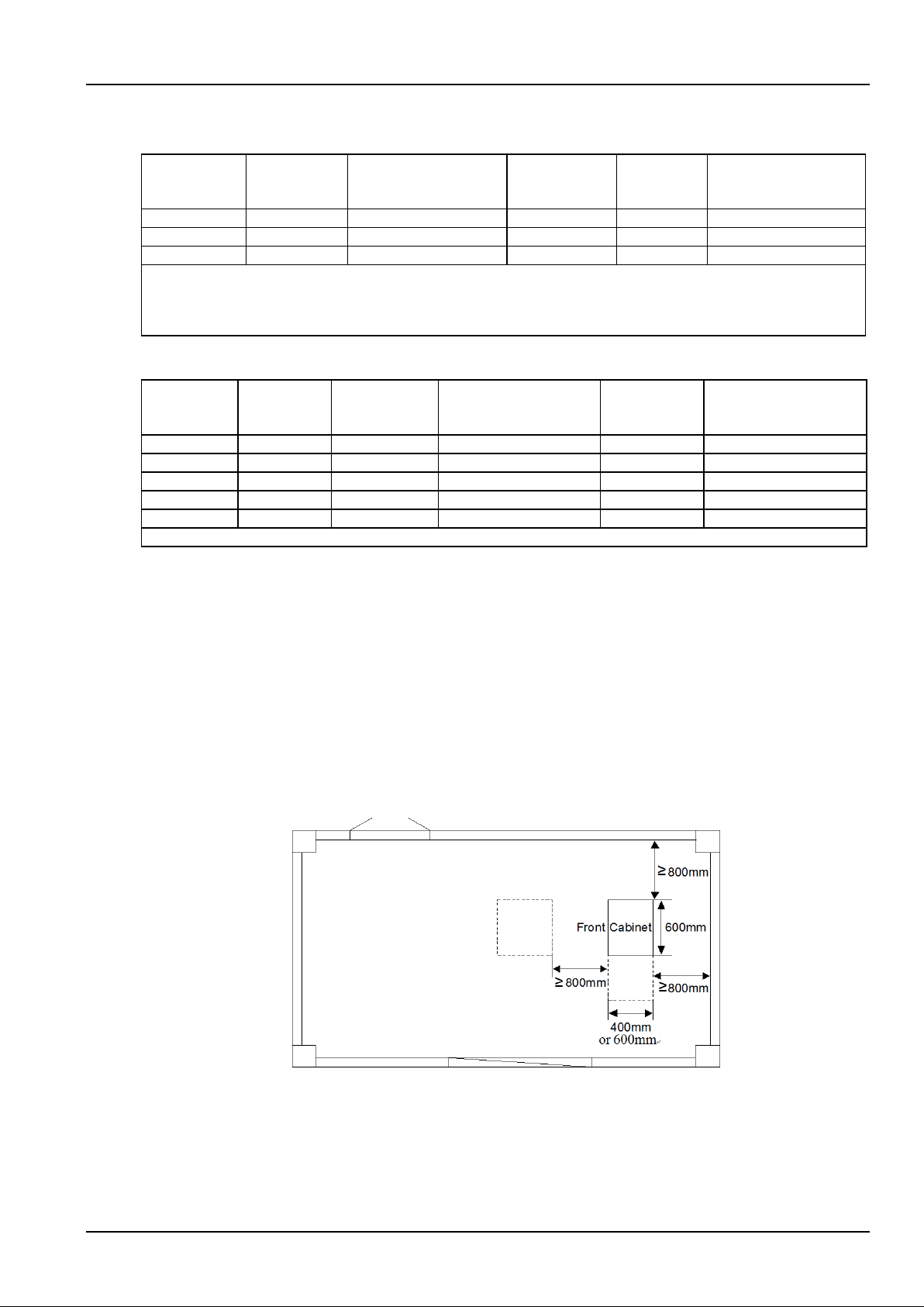
1. Mark the specific installation position of the cabinet
Determine the installation position of the power cabinet in the equipment room according to Figure 2-1. (the depth of
NetSure 731 C62-X2 cabinet is 600mm)
Figure 2-1 Locating power cabinet
Page 18
12 Chapter 2 Installation Instruction
NetSure 731 CC2, NetSure 731 C62 Series Power Supply System User Manual
2. Install expansion pipe
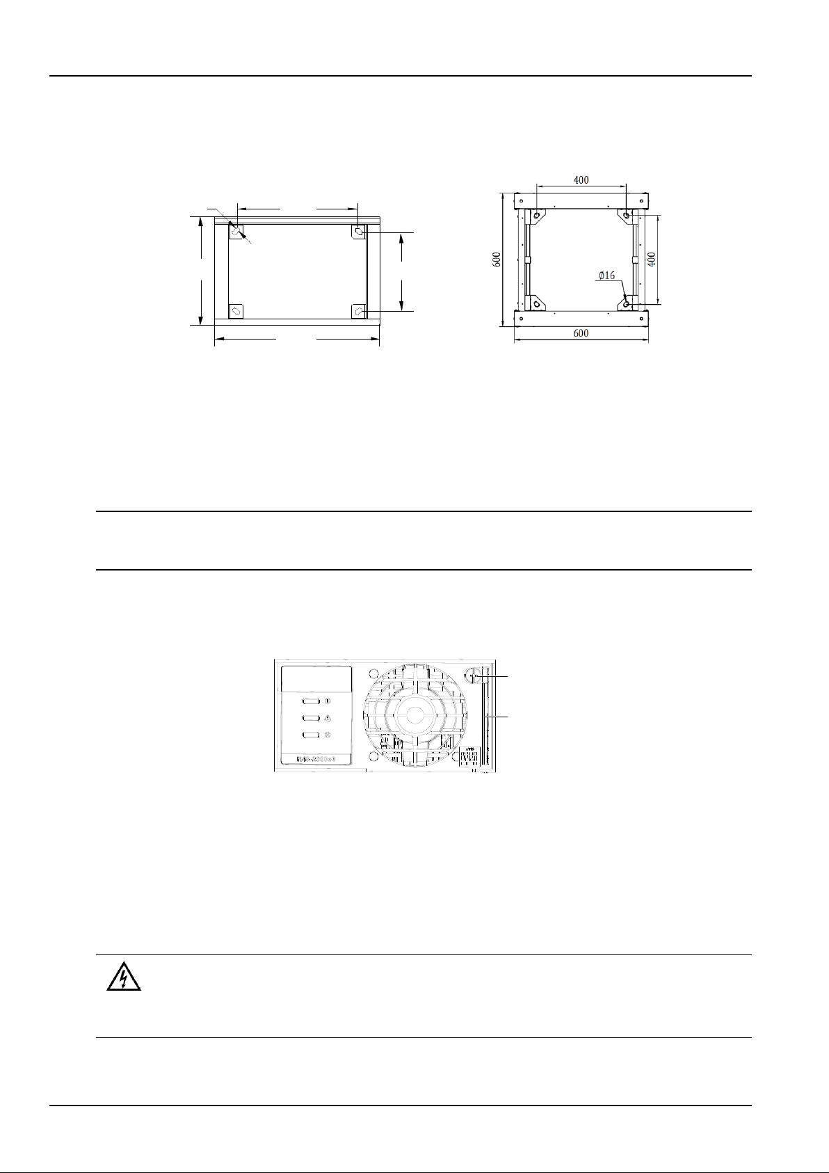
According to Figure 2-2, determine the exact central points of the installation holes on the floor, and mark them with a
pencil or oil pen. Use the electric drill (aiguille: Φ14) to drill holes (depth: 70mm) at the marked points. Clean the
drilled hole of dust. Put the expansion pipe into the hole and knock it with a hammer till it is totally in.
18
436
400 300
600
NetSure 731 CC2 & NetSure 731 C62-X1/X3 NetSure 731 C62-X2
Figure 2-2 Installation size of the cabinet base (unit: mm)
3. Fix the cabinet
Move the cabinet to the installation position. Align the installation holes on the cabinet with the expansion pipes in the
floor. Secure the cabinet with bolts.
2.3.2 Installing Rectifiers
Note
1. In the non-full-configuration, install dummy plates at empty slots.
2. When installing the rectifier, hold the handle and push the rectifier into the slot gently, otherwise the slot may be damaged.
The procedures for installing rectifiers are as follows:
1. After loosing the fixing screw of the handle on the front panel of the rectifier, press the handle (see Figure 2-3) to
pop it up.
Handle
Fixing screw
Figure 2-3 Handle of the rectifier
2. Put the rectifiers in the slot. Push the rectifier completely into the cabinet. Close the handle and tighten the fixing
screw to lock the rectifiers onto the cabinet.
2.4 Electrical Installation
2.4.1 Connecting Power Cables
Danger
Danger
1. Switch off all MCBs and pull out all fuses before the electrical connection.
2. Only qualified personnel shall do the power cable connection.
The power systems uses top cabling, and all the cables should be introduced in or led out along the cable binding
beam in the side wall of the cabinet.
Page 19
Chapter 2 Installation Instruction 13
NetSure 731 CC2, NetSure 731 C62 Series Power Supply System User Manual
Connecting grounding cable
Connect one end of the grounding cable to the user earth bar of the equipment room, and the other end to the
grounding terminal of the power system. Put the cable through the fixing holes at the top of the cabinet. Use the cable
ties to fix the modem on the top of the cabinet, as shown in Figure 2-8. Taking NetSure 731 CC2-X3/X4 and NetSure
731 C62-X1 power system as an example, the grounding terminal is shown in Figure 2-4. The grounding terminal and
neutral busbar of the NetSure 731 CC2-X1、X2 power system are located under the rectifier subrack. The grounding
terminal position of NetSure 731 C62- X2 and NetSure 731 C62-X1/X3 is same as that of the neutral line busbar.
接地端子
零线母排
Neutral line busbar
Earth terminal
Figure 2-4 Connection terminals (rear view, rear plate removed)
Connecting AC cables
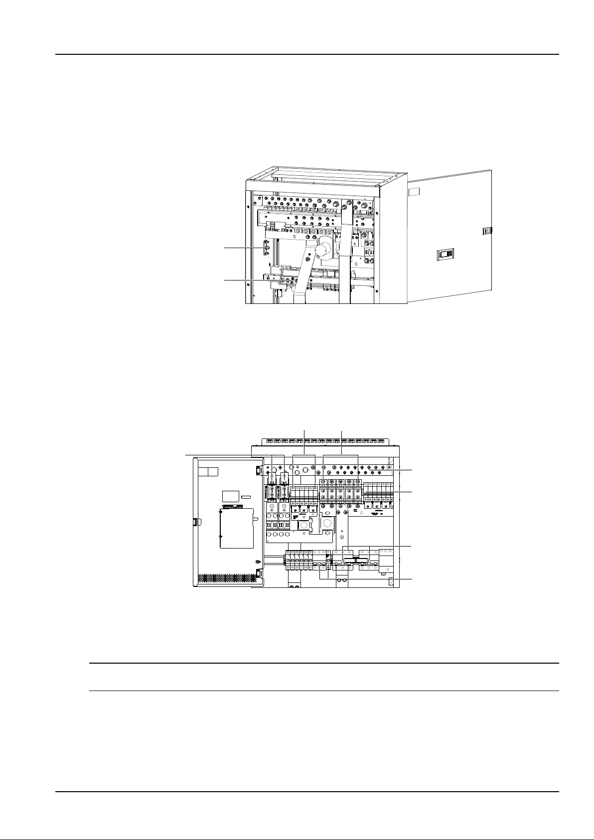
1. Connect the AC input phase cables to the AC input MCBs, as shown in Figure 2-5.
The figure shows the two routes of mains input MCB configuration. NetSure 731 CC2-X3, X4 and NetSure 731
C62-X1, X2, X3 power system only configure one route of mains input MCB, the AC input MCB is shown in Figure
2-5. The AC input MCB, AC output MCB and rectifier MCB of the NetSure 731 CC2-X1, X2 power system are located
in the distribution room below the rectifier subrack.
非重要负载熔断器
重要负载空开
直流输出正母排
电池熔断器
交流输出空开
交流输入空开
非重要负载空开
Priority load MCB
Non-priority load fuse
DC output positive busbar
Non-priority load MCB
AC input MCB
AC output MCB
Battery fuse
Figure 2-5 Connection terminals (front view)
2. If the power system is configured with AC output MCB, connect the AC out cables to the AC output MCB, and
connect the AC out neutral line to the neutral busbar, as shown in Figure 2-4 and Figure 2-5.
Connecting load cables
Note
The total capacity of the priority loads should not exceed 100A.
Connect the negative load cable to the upper terminal of the load MCB or load fuse. Connect the positive load cable
to the DC positive busbar, as shown in Figure 2-5. The specifications of the positive busbar connection screw are ¢
8mm and ¢6mm. Please connect the load cable according to the priority load and non-priority load labels.
Page 20
14 Chapter 2 Installation Instruction
NetSure 731 CC2, NetSure 731 C62 Series Power Supply System User Manual
Connecting battery cables
Note
1. The batteries may have dangerous current. Before connecting battery cables, make sure that the battery fuses at the system side
and the battery MCBs at the battery side are switched off. If there are no battery MCBs at the battery side, users should
disconnect any one of the connectors between battery cells to avoid live state of the power system after installation.
2. Be careful not to reversely connect the battery. Otherwise, both the battery and the power system will be damaged!
3. When the load capacity exceeds 200A, it is recommended to connect two routes of batteries.
1. Connect one end of the negative battery cable to the upper terminal of the battery fuse. Connect one end of the
positive battery cable to the DC positive busbar. The positions of the connection terminals are shown in Figure 2 -5.
The specifications of the positive busbar connection screw is ¢10mm.
2. Connect OT lugs to the other end of the two battery cables. Wrap all the bare parts with insulating tape, and put
them beside the battery. Do not connect the cables to the battery until the DC distribution unit is to be tested.
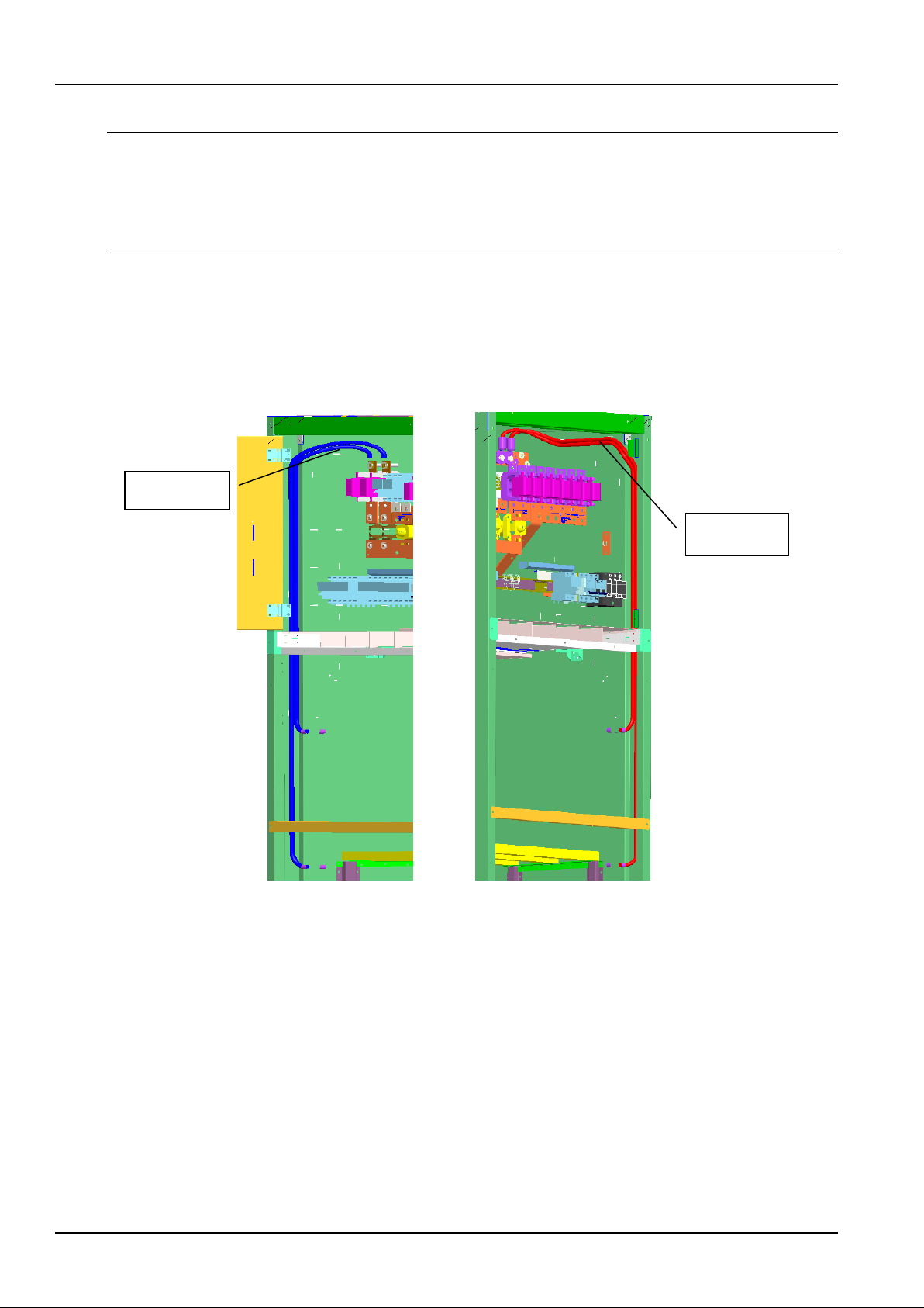
3. The wiring path of battery cable configured in NetSure 731 C62-X2 is shown in Figure 2-6.
Figure 2-6 Battery cable wiring path of NetSure 731 C62-X2
2.4.2 Connecting Signal Cables
All the signal cables are connected to the controller. The position of the controller is shown in Figure 1-2 and Figure
1-3.
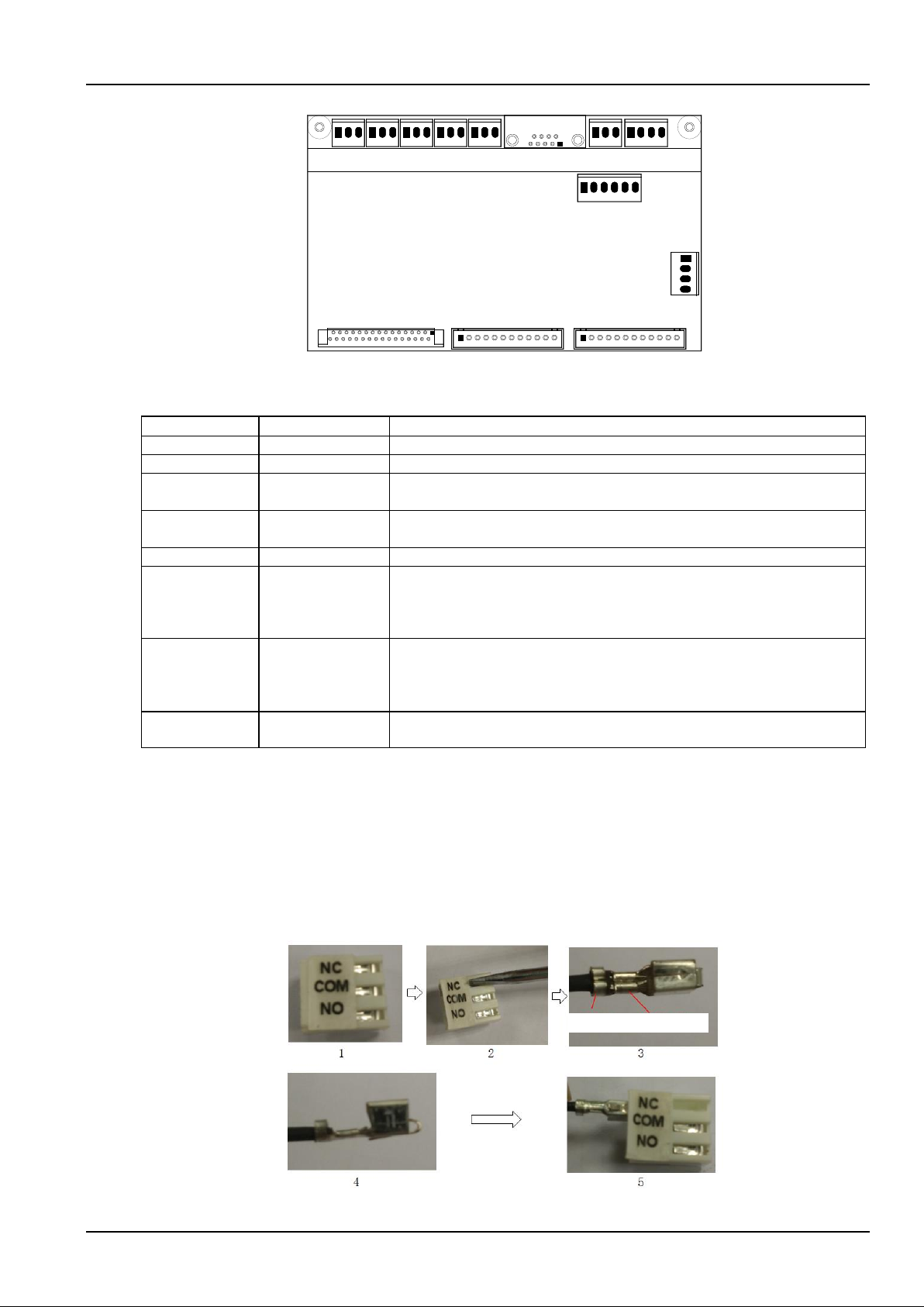
The interfaces of the controller are shown in Figure 2-7. The functions of the interfaces are listed in Table 2-4.
Battery
negative cable
Battery
positive cable
Page 21
Chapter 2 Installation Instruction 15
NetSure 731 CC2, NetSure 731 C62 Series Power Supply System User Manual
1
5
9
6
J1 J2
J3
J4 J5
J6
J9
J10
J12J11
T
emp
RS232
M522S
J7
J8
Figure 2-7 Interfaces of the controller
Table 2-4 Interface functions
Interface
Definition
Connection
J1 ~ J5
Dry contact output
To signal cables
J6
RS232 port
To modem or host
J7
Battery temperature
sensor interface
Connected before delivery
J8
Pow er interface of
the controller
Connected before delivery
J9_1 and J9_2
CAN interface
Connected before delivery
J10_1 and J10_2
LLVD
normally-closed
contact
The signal terminal has been connected to the PCB before delivery
LLVD normally-closed contact, when this interface is connected, the LLVD contactor
is controlled by the controller. Refer to 4.7.2 Battery Settings for the method of
controlling LLVD contactor
J10_3 and J10_4
BLVD
normally-closed
contact
The signal terminal has been connected to the PCB before delivery
BLVD normally-closed contact, w hen this interface is connected, the LLVD contactor
is controlled by the controller. Refer to 4.7.2 Battery Settings for the method of
controlling BLVD contactor
J11 and J12
Detect and alarm
interface
To battery shunt sampling, battery fuse and alarm cables of output routes
Procedures for connecting signal terminal J1 ~ J5:
Step 1: Unplug the signal terminal connector from the monitoring board;
Step 2: Use a slotted screwdriver, press the raised part of the terminal hardly, and push it out from the shell.
Step3: Peel off the insulation outer layer (about 3mm), as shown in Figure 2-8. Then press the naked wire and
insulation out layer.
Step 4: The well-compacted terminal is shown in Figure 2-8.
Step 5: Plug the terminal into the terminal shell, as shown in Figure 2-8.
Press insulation
out layer
Press naked
wire
Figure 2-8 Connecting J1-J5 signal terminal
Page 22
16 Chapter 2 Installation Instruction
NetSure 731 CC2, NetSure 731 C62 Series Power Supply System User Manual
Connecting temperature sensor
The temperature sensor is an optional accessory.
Probe operating voltage: 12V.
Measurement range: -5°C ~ +100°C.
Measurement precision: ± 2°C.
When installing the temperature sensor, put the temperature probe in the battery room that best represents the
battery temperature, far away from other heat-generating equipment. When the batteries are placed outside the
cabinet, the temperature probe shall not be placed inside the cabinet.
Installing modem
Modem is an optional accessory, suitable for those who have purchased the modem remote monitoring system.
The following expounds the modem installation and connection, taking e-TEK TD-5648DCII modem for example.
1. Fix the modem
Put the cable ties through the fixing holes at the top of the cabinet. Use the cable ties to fix the modem on the top of
the cabinet, as shown in Figure 2-9.
Modem
Cable tie
Figure 2-9 Position for placing modem
2. Connect modem with the controller
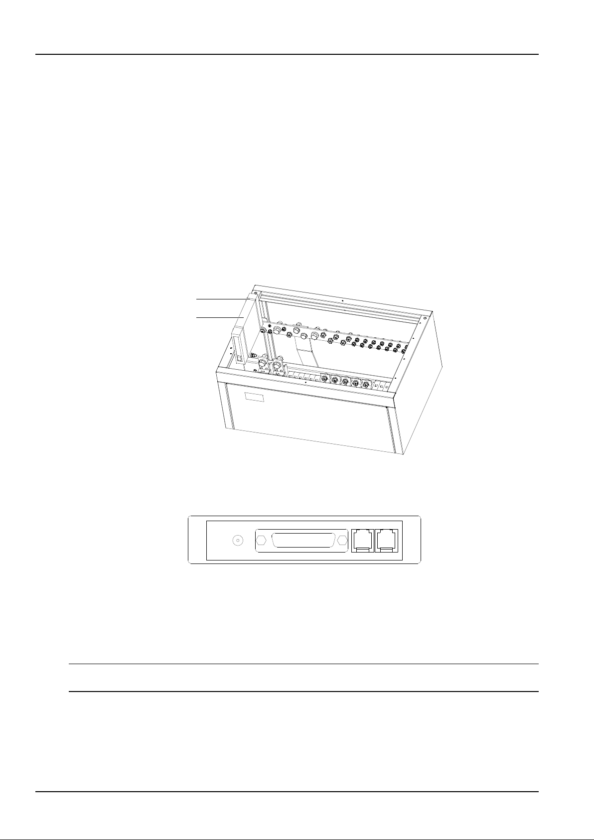
The input and output interfaces of the modem are shown in Figure 2-10.
RS-232
LINE
PHONE
POWER
Figure 2-10 Input & output interfaces of TD-5648DCII Modem
1) Connect a telephone line to the ‘LINE’ interface on the modem.
2) Use a power cable to connect the positive and negative power terminals (screenprint: POWER) of the modem to
the DC positive busbar and negative busbar (below the battery fuse) of the power system respectively.
3) Use a communication cable to connect the communication interface of the modem (DB25 female, screenprint:
RS-232) to the J6 interface (DB9 male) of the controller.
Note
During system testing, set the parameter ‘M odem’ of the controller to ‘Y’.
Connecting dry contacts
The controller provides five pairs of dry contacts, which are J1 ~ J5 interfaces shown in Figure 2-7. Peel one end of
the signal cable (optional) and insert it into the J1 ~ J5 sockets. The functions of the dry contacts are given in Table
2-5.
Page 23
Chapter 2 Installation Instruction 17
NetSure 731 CC2, NetSure 731 C62 Series Power Supply System User Manual
Table 2-5 Dry contact functions
Interface
Function
Interface
Function
J1
AC mains failure
J4
LLVD
J2
DC over/undervoltage
J5
BLVD
J3
Rectifier failure
Note: The above functions are default settings. Users can change them through the controller
2.4.3 Bottom Cabling Cabinet
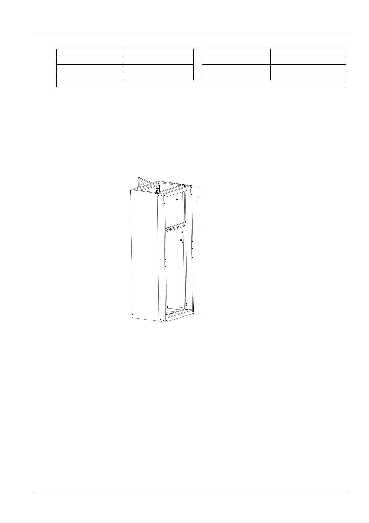
If the cabinet must use bottom cabling method, a rear cover plate should be installed at the rear of the cabinet. User
should follow the procedures below to install the cover plate. (Note: The bottom cabling method is not applicable to
NetSure 731 C62-X2.)
1. Remove the original rear cover plate of the cabinet, and then install the new rear cover plate (100mm thickness) in
the main frame of the cabinet. First install one screw on both of the right and left vertical pole of the new rear cover
plate respectively. Then fix the upper and lower beam, and the cable binding beam in the middle of the cabinet.
Finally, install the other screws on both of the right and left vertical pole, as shown in Figure 2-11.
Beam
screw on the left and right column
Cable bindong beam
Beam
Figure 2-11 Rear cover plate installation for bottom cabling method (1)
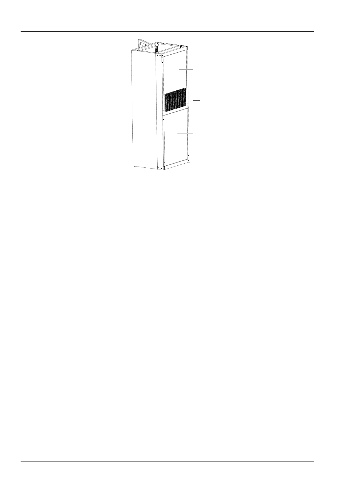
2. Install the original rear cover plate on the outside of the new one, as shown in Figure 2-12.
Page 24
18 Chapter 2 Installation Instruction
NetSure 731 CC2, NetSure 731 C62 Series Power Supply System User Manual
后盖板
Back cover
Figure 2-12 Rear cover plate installation for bottom cabling method (2)
Page 25

Chapter 3 Testing 19
NetSure 731 CC2, NetSure 731 C62 Series Power Supply System User Manual
Chapter 3 Testing
This chapter introduces the testing procedures after installation. The corresponding safety rules shall be adhered to in
the test.
3.1 Installation Check And Startup
Before the test, inform the chief manufacturer representative. Only trained electrical engineers shall maintain and
operate the power system. In operation, the installation personnel are not allowed to wear conductive objects such as
watches, and rings.
During operation, parts of this power system carry hazardous voltage. Misoperation can result in personnel injury and
property loss. Before the test, check the equipment to ensure the proper earthing. Installation check must be done
before testing. Then the batteries can be charged for the first time.
Make sure that the AC input MCBs, rectifier MCBs and load MCBs are switched off. Make sure that all the devices
are properly installed.
Check the power system step by step according to the following listed items.
Installation check
Check item
OK
Comments
Check all the models of MCBs, fuses and cables are correct
Check the busbar connections, input and output cable connection, and connection between the power
system and the system grounding are correct
Check whether the number and connections of the batteries are correct; check the polarity of the battery
string are correct
Make sure all the connections are solid and reliable
Make sure all the communication cables and alarm cables are connected to the controller. Check that the
temperature sensor, if any, has been installed
Startup preparations
Check item
OK
Comments
Make sure that all the MCBs are sw itched off and all the fuses are removed
Measure the AC input voltage. Make sure the input voltage is within the allowable range
Umin= V
Check that at least one short-circuit copper bar in battery string circuit is not connected before installation,
prevent short-circuit caused by positive and negative short-connect
Connect the disconnected batteries to the battery string circuit
Measure with a voltmeter across the connection points of each battery and make sure that the polarity is
right. For a lead-acid battery with 24 cells, the voltmeter should read 2.0V ~ 2.1V/cell or 48V ~ 51V/battery.
If the voltage of certain cell is lower than 2.0V, that cell must be replaced
Umin= V
Check with an ohmmeter that there is no short circuit between the positive & negative distribution busbars,
or between the positive & negative battery poles (Note: Pull out all the rectifiers before the check and
restore them after the check)
Startup
Check item
OK
Comments
Switch on the AC input MCB. Switch on one rectifier MCB. The green LED on the rectifier w ill be on and the
fan w ill start running after a certain delay. The controller will show that the pow er supply voltage is 53.5V
Check the voltage and busbar polarity with a voltmeter. The voltage difference between the measured value
and displayed value should be less than ±0.3V
Start and stop each rectifier of the power system by switching on and sw itching off the rectifier MCBs.
Check their output voltages
Page 26

20 Chapter 3 Testing
NetSure 731 CC2, NetSure 731 C62 Series Power Supply System User Manual
3.2 Basic Settings
When the power system is put into service for the first time, the parameters of controller must be set based on the
actual system configuration, such as battery string number, capacity, user’s charge current limi t and other functional
requirements. Only after that can the controller display system operation information and control the output.
Select the main menu Settings (password: 1) Battery Settings Basic Settings. Set the ‘Mode’ parameter to
‘Manual’. Return to the Settings menu to set the parameters in relative submenus. Refer to 4.7 Setting Parameters.
Check item
OK
Comments
The power supply system model has been set correctly in factory before delivery, check that the setting
agrees with the actual situation. (The system models are: NetSure 731 C62: 48V/300; NetSure 731 CC2:
48V/500)
The battery string number set at the controller should be the same as the number actually connected. By
default: 2
Set the battery capacity at the controller according to the actual capacity of the battery connected to the
power supply system. By default: 300Ah
Configure the temperature compensation coefficient at the monitoring module according to the battery
manufacturer’s requirement. Setting range: 0 ~ 500mV/°C. By default: 72mV/°C. (if no temperature sensor is
installed, do not set this parameter)
Set the charge current limiting point. Setting range: 0.1C10 ~ 0.25C10. By default: 0.1C10
Set the monitoring module according to the voltage suggested by the battery supplier.
Floating Charge (FC) voltage range: 42V ~ Boost Charge (BC) voltage. By default: 53.5V.
BC voltage range: FC voltage ~ 58V. By default: 56.4V.
For batteries that do not need BC, set the BC voltage to FC voltage plus 0.1V
Measure the battery voltage w ith a multimeter and record it. Enter Main menu Maintenance (password: 1)
RectTrim submenu. Set the output voltage of the rectifier to the value of the battery voltage. Insert the
battery fuse. Set the output voltage of the rectifier to 53.5V
Enter the Basic Parameters submenu. Set the ‘Mode’ parameter to ‘Auto’
3.3 Alarm Check And System Operation Status Check
Alarm check
Check that all functional units can trigger alarms that can be displayed on the controller.
Check item
OK
Comments
Pull out one rectifier. The ‘Rect N Com Failure’ alarm should be triggered. Insert the rectifier in. The alarm
should disappear. Repeat the same procedures on other rectifiers
Remove battery fuse 1. The ‘Batt1 Failure’ alarm should be triggered. Put on the fuse. The alarm should be
cleared. Repeat the same on battery fuse 2
Switch off a load MCB connected to a load route. The alarm ‘Load Fuse N Failure’ should be triggered.
Switch on the MCB, and the alarm should be cleared. Repeat the same on the other load MCBs
Remove all the battery input fuses. Keep only one rectifier in operation. Through the controller, adjust the
rectifier FC voltage to make it lower than the alarm point. The alarm ‘DC Voltage Low ’ should be triggered
Pull out the varistor of the AC SPD. The ‘SPD fault’ alarm should be triggered. Insert the varistor, the alarm
should be cleared
Note: When the preceding alarms are generated, the controller will give alarms after approximately 3s. For
querying the alarm information in the controller, please refer to 4.5 Quering Alarm Information
System operation status check
There’s no alarm if the system works normally. User can check whether the system runs normally through the
controller. For querying the controller parameters, please refer to 4.3 Querying System Main Information and 4.4
Querying Rectifier Status.
Check item
OK
Comments
The system models are NetSure 731 C62: 48V/300; NetSure 731 CC2: 48V/500
The controller should display the correct AC voltage
The controller should be able to display the DC voltage. The difference between the displayed voltage and
that measured at the busbar with should be less than ± 0.3V
Page 27
Chapter 3 Testing 21
NetSure 731 CC2, NetSure 731 C62 Series Power Supply System User Manual
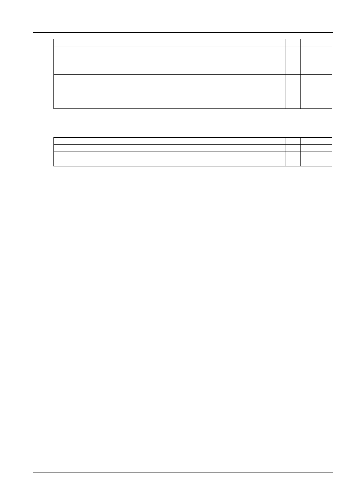
Check item
OK
Comments
The controller should display the battery current. The difference between the displayed and measured
battery current should be less than 1%
Check the number of the rectifier through the controller. The number should be consistent with the settings
and actual values
Check the voltage, current, current limiting point of rectifiers through the controller. They should agree with
the actual parameters
For the power system configured with temperature sensor, the battery and ambient temperature displayed
by the controller should be normal. Hold the probe of the temperatures sensor and the displayed
temperatures should change
3.4 Final Steps
Check item
OK
Comments
Make sure that materials irrelevant to the equipment have been all removed
Fill in the installation report and hand it over to the user
Fill in the parameter table at the cabinet door
If any defect is found in this equipment, inform the personnel responsible for the contract.
If repairing is needed, please fill in the FAILURE REPORT and send the report together with the defective unit to the
repairing center for fault analysis.
Page 28
22 Chapter 4 Use Of The Controller
NetSure 731 CC2, NetSure 731 C62 Series Power Supply System User Manual
Chapter 4 Use Of The Controller
This chapter introduces the operation panel indicators and functional keys of the controller briefly, and expounds the
main screen contents, access method, system controlling, information querying and parameter setting.
When the controller is powered on, the language selection screen will appear. The default language is Chinese, and
you do not need to do any operation. Then the controller will be initialized. After the initialization, the first system
information screen will appear.
4.1 Operation Panel
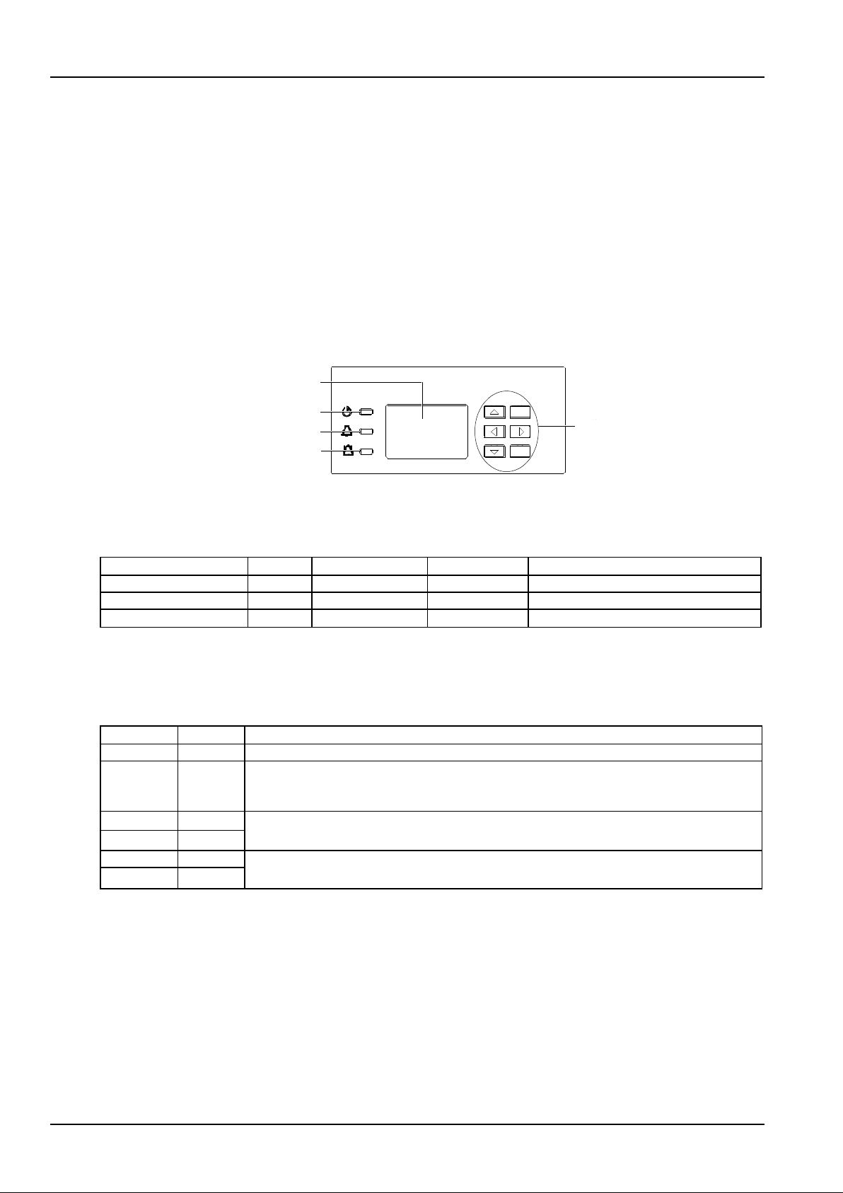
The operation panel of the controller provides the backlit LCD, functional keys and indicators, as shown in Figure 4-1.
ESC
ENT
运行指示灯
告警指示灯
紧急告警指示灯
操作键
液晶显示屏
操作面板
监控单元前面板
Functional keys
LCD
Run indicator
Alarm indicator
Critical alarm indicator
Figure 4-1 Operation panel of the controller
Description of the indicators on the operation panel is given in Table 4-1.
Table 4-1 Description of the controller indicators
Indicator
Color
Normal state
Fault state
Fault cause
Run indicator
Green
On
Off
No operation power supply
Alarm indicator
Yellow
Off
On
There are observation alarms
Critical alarm indicator
Red
Off
On
There are major or critical alarms
The controller uses a 128 × 64 LCD unit, and a keypad with six functional keys. The interface language is
Chinese/English optional (8 × 4 Chinese characters can be displayed). Table 4-2 shows the description of the
controller functional keys.
Table 4-2 Description of the controller functional keys
Screenprint
Name
Function
ESC
Escape
Return to the upper level menu. When the audible alarm is generated, press this key to cancel it
ENT
ENT
Enter the lower level menu or confirm the menu operation. When changing or inputting parameters,
press this key to get into editing state. After any change is made, press this key to validate the
change
▲
Up
Shift among parallel menus. For a character string, these two keys can be used to change values
▼
Down
Left
In value setting interface, these two keys can be used to change values. These two keys can move
the cursor, only w hen one LCD screen requires character string to be input
Right
4.2 Main LCD Screens
The following LCD screens will be mentioned in this chapter for many times. This section is a centralized introduction
about the contents and access methods of these LCD screens.
4.2.1 System Information Screen
When the controller is powered on, the language selection screen will appear. The default language is English, and
you do not need to do any operation. Then the controller will be initialized. After the initialization, the first system
information screen will appear.
Page 29
Chapter 4 Use Of The Controller 23
NetSure 731 CC2, NetSure 731 C62 Series Power Supply System User Manual
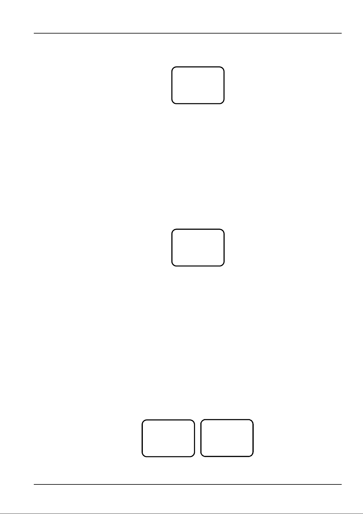
The system information screen shows the main information, which is displayed on five pages. You can press ▲ or ▼
repeatedly to select different system information screens. The first system information screen has 7-level contrast,
you can press ◄ or ► to adjust the LCD contrast. The first system information screen is shown in Figure 4-2.
2009-3-23
53.5V 125A
Float
NormalAuto
Figure 4-2 First system information screen
1. The first row displays the date and time alternately.
2. At the main menu screen, press the ESC key to return to the first system information screen.
3. If no operation is conducted on the controller keypad for eight minutes, the LCD screen will return to the first
system information screen. The time of that return will be recorded, and can be queried through the host.
4. At any one of the system information screen, press the ESC key to display the serial No., software version and
runtime of the controller.
5. At the system information screen, pressing and holding the ESC and ENT keys simultaneously for several seconds,
resets the controller, and restarts the system.
4.2.2 Password Confirmation Screen
During operation, some controllers will prompt you to enter password, as shown in Figure 4-3. Only the correct
password allows you to enter the screen you need to operate.
Login:
Password:
Figure 4-3 Password confirmation screen
When inputting the password, use the ENT key to get into editing state, use ▲ or ▼ to modify numbers, and use ◄
or ► to move the cursor. After the input, press the ENT key to confirm. If the password is correct, the next screen will
appear. Otherwise, the system will prompt ‘Password incorrect’. During this operation, pressing the ESC key returns
to the main menu screen.
The controller has three password levels: user level password (default: 1), engineer level password (default: 2)and
administrator level password (default: 640275).
Once you enter the correct password, you never need to enter the password again during the operation. If the interval
between adjacent operations is more than four minutes, the system will prompt you to input the password again.
Therefore, if you want to enter senior setting screens, you need to wait four minutes and cannot do any operation
during waiting, and then the system will enter the senior setting screens after you input the higher level password. If
the two level passwords are the same, the controller will display the senior menus after you enter the password.
4.2.3 MAINMENU Screen
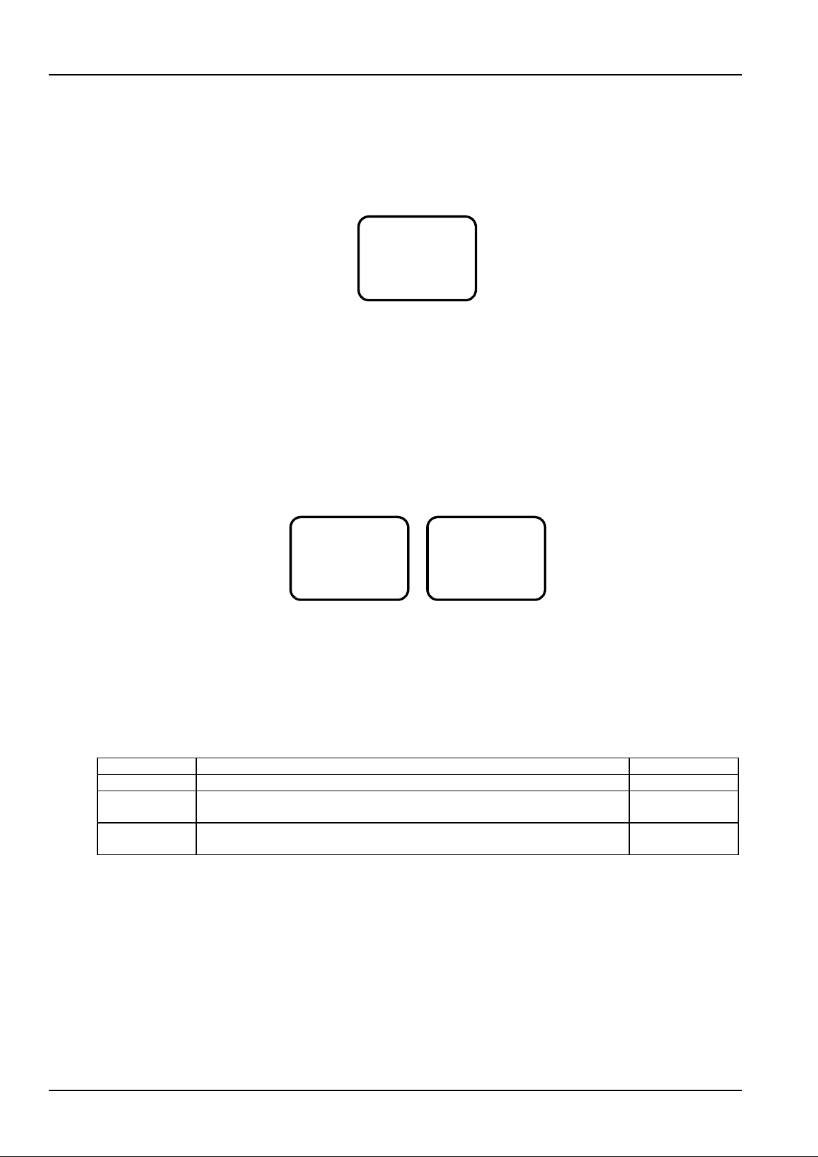
The main menu is the highest-level menu of the controller. At the sub-menus of this screen, you can query the
settings, controls, rectifiers and alarms information of the power system. The main menu screen is shown in
Figure 4-4.
MAINMENU
Status
Settings
Maintenance
Energy Saving
Fast Settings
Figure 4-4 MAINMENU screen
1. At any one of the system information screen, press the ENT key to enter the MAINMENU screen.
Page 30
24 Chapter 4 Use Of The Controller
NetSure 731 CC2, NetSure 731 C62 Series Power Supply System User Manual
2. At any sub-menu of the MAINMENU screen, press the ESC key repeatedly to return to the higher-level menu, and
ultimately to the MAINMENU screen.
4.2.4 STATUS Screen
The STATUS screen is a sub-menu of the main menu. It contains rectifiers, active alarm and history alarm. The
STATUS screen is shown in Figure 4-5.
STATUS
Rectifiers
Active Alarm
History Alarm
Figure 4-5 STATUS screen
1. At the MAINMENU screen, press ▲ or ▼ to select the ‘STATUS’ m enu, and press the ENT key to enter the
STATUS screen.
2. At any sub-menu of the STATUS screen, press the ESC key repeatedly to return to the higher-level menu, and
ultimately to the STATUS screen.
4.2.5 Settings Screen
Displayed in two screens, the Settings screen is a sub-menu of the main menu. It is used to set all the parameters of
the power system. The Settings screen has password protection, only the correct password allows you to enter it.
See Figure 4-6 for the Settings screen.
Settings
Alarm Setting
Bat. Settings
AC Settings
DC Settings
Rect Settings
Sys Settings
Comm Settings
Figure 4-6 Settings screen
1. At the MAINMENU screen, press ▲ or ▼ to select the ‘Settings’ menu, and press the ENT key to enter the
password confirmation screen.
2. Input the correct password and press the ENT key to enter the Settings screen. Press ▲ or ▼ to enter the screen
you need.
In the settings screen, each password level has different authority. See Table 4-3 for the operation authorities.
Table 4-3 Password levels and operation authorities
Passw ord level
Operation authority
Default password
User
General parameter settings
1
Engineer
All the user’s authorities, plus operation authorities such as resetting system, resetting
password and changing system type
2
Administrator
All the engineer’s authorities, plus operation authorities such as modifying passwords,
controlling alarm volume and browsing system parameters set by host
640275
Once you enter the correct password, you never need to enter the password again during the operation. If the interval
between adjacent operations is more than four minutes, the system will prompt you to input the password again.
Therefore, if you want to enter senior setting screens, you need to wait four minutes and cannot do any operation
during waiting, and then the system will enter the senior setting screens after you input the higher level password. If
the two level passwords are the same, the controller will display the senior menus after you enter the password.
4.2.6 Maintenance Screen
Displayed in two screens, the Maintenance screen is a sub-menu of the main menu. It is used to control the system in
real time. The Maintenance screen has password protection, only the correct password allows you to enter it. For this
screen, the user level password, engineer level password and administrator level password all have the same
authority. The Maintenance screen is shown in Figure 4-7.
Page 31

Chapter 4 Use Of The Controller 25
NetSure 731 CC2, NetSure 731 C62 Series Power Supply System User Manual
Maintenance
Start: FC
Batt: ReConnect
Load: DisConn
RectTrim: 53.5V
RectLimit: 121%
Figure 4-7 Maintenance screen
1. At the MAINMENU screen, press ▲ or ▼ to select the ‘Maintenance’ menu, and press the ENT key to confirm.
The system will prompt you to input the password if the ‘Sys Mode’ is set to ‘Manual’ (see 4.7.2 Battery Settings for
setting method).
2. Input the correct password and press the ENT key to enter the Maintenance screen. Press ▲ or ▼ to enter the
screen you need.
4.2.7 Energy Saving Screen
The Energy Saving screen is a sub-menu of the main menu, as shown in Figure 4-8. It is used to set the relevant
parameters for energy saving.
Save Enable: Y
Cyc Period: 168h
Rect Work: 80%
Rect Limit: 1
Figure 4-8 Energy saving screen
1. At the MAINMENU screen, press ▲ or ▼ to select the ‘Energy Saving’ menu, and press the ENT key to display
the password confirmation screen.
2. Input the correct password and press the ENT key to enter the Energy Saving screen. Press ▲ or ▼ to select the
parameters you need.
4.2.8 Fast Settings Screen
The Fast Settings screen is a sub-menu of the main menu, as shown in Figure 4-9. It is used to set the system type
and battery capacity.
System Type:
48V/SET
Capacity: 300Ah
600Ah
Figure 4-9 Fast settings screen
1. At the MAINMENU screen, press ▲ or ▼ to select the ‘Fast Settings’ screen, and press the ENT key to display the
password confirmation screen.
2. Input the correct password and press the ENT key to enter the Fast Settings screen. Press ▲ or ▼ to select the
parameters you need.
4.3 Querying System Main Information
DC, system state, battery state and energy management mode information
At any one of the system information screen, press ▲ or ▼ repeatedly to enter the first system information screen. At
other screens, press the ESC key repeatedly to return to the first system information screen. DC voltage and current,
system state, battery state and energy management mode information are all displayed in the first system information
screen, as shown in Figure 4-10.
Page 32
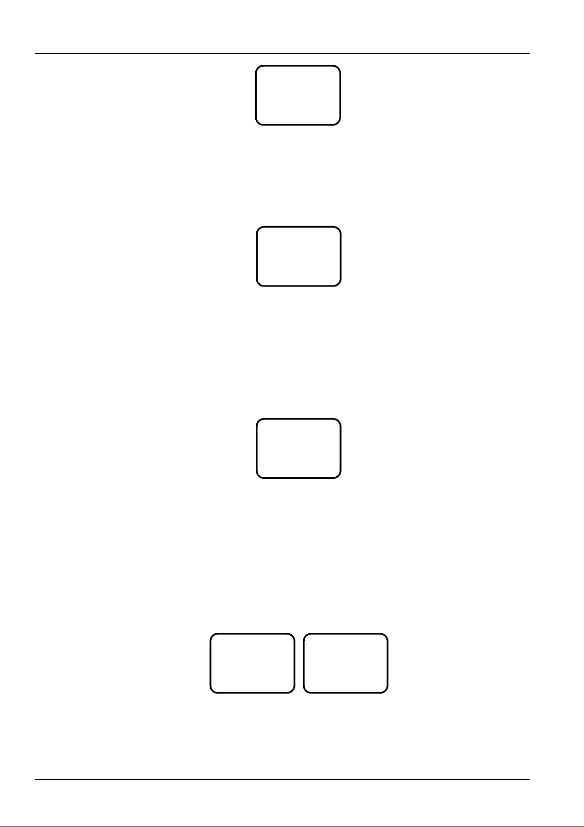
26 Chapter 4 Use Of The Controller
NetSure 731 CC2, NetSure 731 C62 Series Power Supply System User Manual
2009-3-23
53.5V 125A
Float
NormalAuto
Figure 4-10 First system information screen
The date and time are alternately displayed every two seconds. The system state contains Normal and Alarm. The
energy management mode includes Auto and Manual. The battery state includes Float, Temp Comp, Boost, Cyclic
Boost, Batt. Test, ShortTest and TimeTest.
Save state, rectifier output power and cyclic BC after information
At the first system information screen, press ▼ to enter the screen shown in Figure 4-11.
Save Stat: Y
Sys Used: 80.0%
Cyc BC After:
2400h
Figure 4-11 Save state, output power and cyclic BC after information screen
The first row displays the save state. The second row displays the percentage ratio of the rectifier output power to the
rectifier rated power. The last two rows display the boost charge prompt information, they will be different for different
states of the power system, including:
1. Prompt the time of the next cyclic BC according to the battery state.
2. If BC is going on or prohibited, ‘---’ will be prompted.
Battery and remain information
At the screen shown in Figure 4-11, press ▼ to view the battery information shown in Figure 4-12.
Batt1: 0A
Remain: 100%
Batt2: 0A
Remain: 100%
Figure 4-12 Battery information screen
‘Batt1’ and ‘Batt2’ in the preceding screen represent respectively the current that flowed through battery shunt 1 and
battery shunt 2. If several battery strings are connected to one shunt, the displayed current is their total current; if the
‘Shunt Coeff’ of one battery string is set to ‘N’, the corresponding battery information will display ‘None’, and the
remaining capacity will not be displayed.
The remaining battery capacity can be displayed in percentage (default), remaining ampere hours and remaining
time.
AC voltage information
At the battery information screen, press ▼ to display the AC information page. The system will display AC voltage of
the A, B and C phases, as shown in Figure 4-13.
AC 1 Volt
Phase A: 0V
Phase B: 0V
Phase C: 0V
AC 2 Volt
Phase A: 0V
Phase B: 0V
Phase C: 0V
Figure 4-13 AC information screen
System temperature information
At the AC information screen, if a temperature sensor is configured, pressing ▼ displays the screen shown in
Figure 4-14.
Page 33
Chapter 4 Use Of The Controller 27
NetSure 731 CC2, NetSure 731 C62 Series Power Supply System User Manual
Bat.Temp:
25°C
Figure 4-14 Battery temperature screen
If the temperature sensor is not connected or is faulty, the system will prompt ‘---’. Meanwhile, the alarm information
screen will be displayed. If the controller bans BC and no temperature sensor is configured, this screen will not be
displayed.
4.4 Querying Rectifier Status
Note
If the controller has not detected rectifiers, you cannot query the rectifier information.
The rectifier information includes the serial No., output voltage, output current, current limit, input voltage, AC and DC
states, AC power limit and temperature power limit of each rectifier.
At the STATUS screen (see Figure 4-5), press ▲ or ▼ to select the ‘Rectifiers’, and press the ENT key to enter the
screen shown in Figure 4-15.
Rect 1:
ID: 01060700584
Out Volt: 53.5V
Out Curr: 38.5A
Curr Limit: 110%
In Volt: 220V
AC State: On
DC State: On
AC Derated: N
Temp Derated: Y
Figure 4-15 Rectifier information screen
The information of every rectifier is displayed in three screens. Press ▲ or ▼ to scroll to the three information
screens. Press ◄ or ► to query other rectifiers ’ information. At most 24 pieces of rectifier information can be
displayed in the controller. When selecting one rectifier, the green indicator of the rectifier will blink. If the rectifier
communication is interrupted, the information will be displayed in high light.
4.5 Querying Alarm Information
You can query the active alarms and history alarms through the LCD of the controller. The query methods are given
in the following sections.
4.5.1 Querying Active Alarm
When a new alarm is generated, and there is no operation on controller keypad for two minutes, the LCD of the
controller will prompt an active alarm screen automatically. If there are multiple alarms in the current system, you can
query alarms through the following steps.
At the STATUS screen (see Figure 4-5), press ▲ or ▼ to select the ‘Active Alarm’, and press the ENT key to enter it.
1. If there is no active alarm, the alarm prompt will not appear; if there is an active alarm, after entering the active
alarm screen, the alarm will disappear and ‘Active alarm: None’ will appear.
2. If there is an active alarm, the screen shown in Figure 4-16 will appear.
Alarm 1/5
071213 14:27:50
Manual Mode
Observation
Figure 4-16 Active alarm screen
Page 34
28 Chapter 4 Use Of The Controller
NetSure 731 CC2, NetSure 731 C62 Series Power Supply System User Manual
The Figure 4-16 screen includes alarm serial No./ alarm total number, alarm name, alarm level and alarm time. The
alarm generating time determines the sequence it is displayed, with the latest alarm displayed first. Use ▲ or ▼ to
view all active alarms.
When querying the rectifier alarms, pres s ► to display the rectifier ID, and the green indicator of the rectifier will blink.
In case of battery test alarm or maintenance time alarm, press ► to display the prompt information screen, then
press the ENT key to confirm that the alarm is cleared. The active alarms in the controller are given in Table 4-4.
Table 4-4 Active alarm of the controller
No.
Alarm type
Alarm
Description
1
Rectifier alarm
Rect AC Fail
Press ► to browse the serial No. of the faulty rectifier
2
Rect Over Temp
3
Rect Fault
4
Rectifier alarm
Rect Protect
Press ► to browse the serial No. of the faulty rectifier
5
Rect Fan Fails
6
Rect Derated
7
Rect Not Respond
8
Multi-Rect Alarm
9 Rectifier Lost
You can clear this alarm manually
1
AC alarm
SPD Fault
SPD fault is the alarm of Digital 1
2
Digital Alarm
3
AC High
4
AC Low 5
AC PH Fail
6
Mains Failure
1
DC alarm
DC Volt High+
2 DC Volt Low
3 DC Volt Low-
4
Batt Over Temp
5
Batt Temp High Alarm
6 Batt Temp Low Alarm
7 Ambient Temp High Alarm
8 Ambient Temp Low Alarm
9
T No Probe
10
Sensor Fault
11
LVD
12
BLVD 13
Load Fuse Alarm 1
14
Load Fuse Alarm 2
15
Load Fuse Alarm 3
16
Load Fuse Alarm 4
17
Load Fuse Alarm 5
18
Load Fuse Alarm 6
19
Aux Load Fails
20
Batt Fuse Alarm 1
21
Batt Fuse Alarm 2
22
Batt 1 Curr High
1
Battery
management alarm
Non Float Status
2
Batt Discharge
3
Load Share Alarm
4
Batt Test Fail
Press ► to prompt you to clear this alarm
5
Short Test Fail
6
Save Pow er
7 Save Pow er Fault
1
Controller
self-detect alarm
SelfDetect Fail
2 Manual Mode
3
Volt Discrepancy
4
Maintain Alarm
5 Alarm Block
Page 35

Chapter 4 Use Of The Controller 29
NetSure 731 CC2, NetSure 731 C62 Series Power Supply System User Manual
4.5.2 Querying History Alarm
1. At the STATUS screen (see Figure 4-5), press ▲ or ▼ to select the ‘History Alarm’, and press the ENT key to
enter it.
1) If there is no history alarm, the system cannot access the lower level menu.
2) If there is an active alarm, the screen shown in Figure 4-17 will appear.
199 ID2067000584
071213 17:30:05
Rect1 Fault
071213 14:27:50
Figure 4-17 History alarm screen
If the alarm is a rectifier alarm, the first row in Figure 4-17 will display the latter 10 digits of the rectifier ID.
The history alarms of the controller are stored in cyclic order. At most 200 alarms will be recorded, above that, the
earliest alarm will be cleared automatically.
2. Use ▲ or ▼ to view other history alarms.
3. At any History Alarm screen, press the ESC key repeatedly to return to the higher-level menu, and ultimately to the
first system information screen.
4.6 Maintenance
Note
Be careful! BLVD operations may result in load power interruption.
1. From the battery basic parameters, you can change the ‘Sys Mode’ from ‘Auto’ to ‘Manual’, and then press the
ENT key to confirm. For the detailed procedures, see Basic parameters in 4.7.2 Battery Settings.
2. At the MAINMENU screen, pres s ▲ or ▼ to select the ‘Maintenance’ menu. Press the ENT key, the system will
prompt you to input the password.
3. Input the password and press the ENT key to enter the Maintenance screen (displayed in two screens), as shown
in Figure 4-18.
Maintenance
Start: FC
RectTrim: 53.5V
RectLimit: 121%
Rect 1: DC On
Rect 1: AC On
Rect 1: Reset
Figure 4-18 Maintenance screen
4. Press ◄ or ► to select the needed operation, and press the ENT key to confirm. The screen pops up the
corresponding prompt. If the system satisfies control situation, press the ENT key to make the control valid, otherwise,
the controller will prompt you that the control is disabled. Press the ESC key to cancel. The control contents are given
below.
1) Start: The option includes FC, BC and Test. Press ◄ or ► to select the needed action. After selecting the Start
option, press ◄ or ► to select the needed operation. If there is an AC power-off alarm, or the busbar undervoltage,
the boost charge and battery test control will not be executed by the system. No battery test control can be conducted
when the rectifier communication is interrupted. After the battery test, the management mode will be changed from
‘Manual’ to ‘Auto’ autom atically.
2) RectTrim: Range: 42V ~ 58V. The control voltage value of this parameter cannot exceed the overvoltage alarm
point, otherwise, the parameter will be invalid.
3) RectLimit: Range: 10% ~ 121%.
4) Rect: The operations for a single rectifier include: DC On/Off, AC On/Off and Reset.
Operation method:
Page 36

30 Chapter 4 Use Of The Controller
NetSure 731 CC2, NetSure 731 C62 Series Power Supply System User Manual
Use ▲ or ▼ to select the rectifier parameter, and use ◄ or ► to change the rectifier serial No.. Then press the ENT
key to confirm. The bottom row of the screen displays the rectifier ID automatically. Us e ▲ or ▼ to move the cursor
to the operation area (that is, ‘DC On’ in Figure 4-18), and use ◄ or ► to select the value , and then press the ENT
key to confirm.
If a rectifier shuts down due to over-voltage, you can select the Reset order to reset the rectifier once. If the
overvoltage fault disappears afterwards, this rectifier will resume normal operation; otherwise, the rectifier will shut
down again. The control orders of RectTrim, RectLimit and single rectifier can be executed only when the system is in
float charge state.
5. Press the ESC key to return to the MAINMENU screen, and change the management mode from ‘Manual’ to ‘Auto’.
Then press the ESC key to return to the system information screen.
4.7 Setting Parameters
The power system parameters are divided into seven kinds: alarm, battery, AC, DC, rectifier, system and
communication parameters. Without any special needs, you only need to reset the battery string and battery capacity
according to system configuration and battery actual instance, and accept the factory settings for other parameters.
The setting methods of parameters are given in the following sections.
4.7.1 Alarm Settings
At the Settings screen, press ▲ or ▼ to select the ‘Alarm Settings’ menu, then press the ENT key to enter the Alarm
Settings screen, as shown in Figure 4-19.
Alarm Settings
Alarm Level
Alarm Control
DI Settings
Figure 4-19 Alarm settings screen
There are three sub-menus shown as follows.
Setting alarm level
At the Alarm Settings screen, press ▲ or ▼ to select the ‘Alarm Level’ menu. Then press the ENT key to enter the
Alarm Level screen, as shown in Figure 4-20.
Alarm Type:
Load Fuse Alarm
Level: Critical
Out Relay: N
Figure 4-20 Alarm level screen
Press ▲ or ▼ to move the cursor to the needed option. Press ◄ or ► to select the corresponding content and press
the ENT key to confirm.
The controller alarms are classified into four types: critical alarm, major alarm, observation and no alarm.
Critical alarm, major alarm: These two types of alarms have strong impacts on the power system performance.
Whenever these alarms are generated, you are supposed to handle them immediately. The alarm indicators will be
on and audible alarm will be generated.
Observation alarm: When this type of alarm is generated, the power system maintains normal DC output for a while.
If the alarm occurs during watch time, it should be handled immediately. If the alarm occurs during non-watch-time,
handle it during watch time. The alarm indicators will be on when observation alarm occurs.
No alarm: No visual or audible alarm.
The alarm and its default value of the controller are listed in Table 4-5.
Page 37
Chapter 4 Use Of The Controller 31
NetSure 731 CC2, NetSure 731 C62 Series Power Supply System User Manual
Table 4-5 Description of alarm setting parameter
No.
Alarm
Description
Alarm level
Related relay
Related
parameter
1
SPD Fault
Lighting protection circuit failure
Critical
None
2
DI
The alarm name is user-defined, at most 10 letters. In
this system, eight DIs can be defined. Among which, the
first DI is defined as ‘SPD Fault’, the other seven DIs can
be defined by the user
No alarm
None
3
AC Voltage High
The AC input voltage is higher than the setting of AC
input over-voltage alarm point
Critical
None
Over-voltage
alarm
4
AC Voltage Low
The AC input voltage is lower than the setting of AC input
under-voltage alarm point
Critical
None
Low-voltage
alarm
5
Mains Failure
All the AC input voltages from the rectifier are less than
80V
Major
1
6
DC Volt High
The DC output voltage is higher than the setting of DC
output over-voltage alarm point
Critical
2
Over-voltage
alarm
7
DC Volt Low
The DC output voltage is low er than the setting of DC
output under-voltage alarm point
Critical
2
Low-voltage
alarm
8
DC Volt Under
DC output voltage lower than the setting of ‘DC output
under- voltage alarm point’
Observation
None
Under-voltage
alarm
9
Batt Over Temp
The battery temperature is higher than the setting of
over-temperature point
Critical
None
Over Temp
alarm point
10
Batt Temp High
Alarm
The battery temperature is higher than the setting of high
temperature point
Observation
None
High Temp
alarm point
11
Batt Temp Low
Alarm
The battery temperature is lower than the setting of low
temperature point
Observation
None
Low Temp
alarm point
12
Ambient Temp
High Alarm
The ambient temperature is higher than the setting of
high temperature point
Observation
None
High Temp
alarm point
13
Ambient Temp
Low Alarm
The ambient temperature is lower than the setting of low
temperature point
Observation
None
Low Temp
alarm point
14
T No Probe
Configured with temperature sensor, but not connected
Critical
None
15
Sensor Fault
The temperature sensor measures unreasonable
temperature
Critical
None
16
LVD 1
Load low voltage disconnects manually
Critical
5
LLVD enabled
17
LVD 2
Battery low voltage disconnects manually
Critical
4
BLVD enabled
18
Load Fuse Alarm
1 ~ 6
Load failure caused by overload, short circuit, manual
disconnect, or alarm circuit failure
Critical
None
19
Aux Load Fails
The last load fuse fails
Critical
None
20
Batt Fuse Alarm
1 ~ 2
Battery failure caused by overload, short circuit, manual
disconnect, and alarm circuit failure
Critical
None 21
Batt 1 Curr High
The charging current of battery string 1 is higher than the
setting of charging over current limit
Observation
None
Over current
point
22
Batt 2 Curr High
The charging current of battery string 2 is higher than the
setting of charging over current limit
Observation
None
Over current
point
23
Rect AC Fail
The AC input voltage of this rectifier is lower than
under-voltage alarm point
Major
3
24
Rect Over Temp
The internal temperature of the rectifier is higher than 90°
Observation
3
25
Rect Failure
The rectifier voltage is higher than upper limit voltage
Critical
3
26
Rect Protect
The rectifier performs self-protection and has no output
Observation
3
27
Rect Fan Fails
Rectifier fan failure
Major
3
28
Rect Derated
The rectifier limits its output power
Observation
3
29
Rect Not Respond
The rectifier does not communicate w ith the monitoring
unit
Major
3
30
HVSD
The rectifier shuts down under high voltage
Major
3
31
Multi-Rect Alarm
More than two rectifiers alarm
Critical
None
32
Self-detect Err
Hardware self-detect error
No alarm
None 33
Manual Mode
The battery management is in ‘Manual’ mode
No alarm
None 34
Non Float Status
The battery is not under float charge status
No alarm
None 35
Batt Discharge
The battery is discharging
Observation
None
Page 38
32 Chapter 4 Use Of The Controller
NetSure 731 CC2, NetSure 731 C62 Series Power Supply System User Manual
No.
Alarm
Description
Alarm level
Related relay
Related
parameter
36
Load Share Alarm
In the system with load current shunt, the sampled load
current plus battery current differs greatly from rectifier
current
No alarm
3
37
Batt Test Fail
The battery discharging time is shorter than expected
time
Observation
None 38
Short Test Fail
In short test, the battery discharging capacity is bigger
than setting value
Observation
None
39
Volt Discrepancy
The actual output voltage is different from both the
measured DC bus voltage and the voltage reported by
the rectifier to monitoring unit. The error is bigger than 1V
Observation
None
40
Maintain Alarm
Time to maintain the system
Observation
None
41
Rectifier Lost
The monitoring unit has detected a reduction in the
number of running rectifiers
Critical
None
42
Save Pow er
The system is running under energy saving status
No alarm
None
Setting alarm control
At the Alarm Settings screen, press ▲ or ▼ to select the ‘Alarm Control’ menu. Then press the ENT key to enter the
Alarm Control screen, as shown in Figure 4-21.
Alarm Control
Voice Sign: Open
Clear: Hist Alarm
Figure 4-21 Alarm control screen
‘Voice Sign’ option includes: open, off, 3min, 10min, 1h, 4h. You can set it according to your requirements.
‘Clear: Hist Alarm’ option includes: Hist Alarm, Rect Lost, TestFail, ShortTest, ESaveFail and Maintain. If you press
the ENT key, the corresponding alarm information saved in the controller will be cleared.
DI settings
DI settings only have an impact on user-defined DI alarm. At the Alarm Settings screen, press ▲ or ▼ to select the
‘Active: High’ menu, then press the ENT key to enter the DI Settings screen, as shown in Figure 4-22.
Digital 1 Alarm
DI Settings
Active: High
DI No.: 1
Digital 1 Alarm
Active: High
Figure 4-22 DI settings screen
Press ▲ or ▼ to select the needed option. Press ◄ or ► to select the parameter value and press the ENT key to
confirm. Press ▲ or ▼ to modify the number and letter of DI name on the third row after pressing the ENT key to
confirm, and press ◄ or ► to move the cursor left or right, and then input ‘#’ to end. Finally, press the ENT key to
confirm.The value description of the alarm setting parameter is listed in Table 4-6.
Table 4-6 Description of the alarm parameter setting
Parameter
Range
Factory setting
Value description
DI No.
1 ~ 8
1
The eight corresponding connecting terminals, queued up in the order
that the hardware switches are put
DI Name
Figures or letters,
10 at most
SPD
When there are DI alarms, this parameter shows the alarm name you
have defined
Alarm Mode
High, Low
Low
High: alarm upon high level; low: alarm upon low level
4.7.2 Battery Settings
Battery parameters are important, because they are related to the life of battery.
Page 39
Chapter 4 Use Of The Controller 33
NetSure 731 CC2, NetSure 731 C62 Series Power Supply System User Manual
At the Settings screen (see Figure 4-6), press ▲ or ▼ to select the ‘Bat. Settings’ menu, then press the ENT key to
enter the BAT Settings screen, as shown in Figure 4-23.
BAT Settings
Basic Setting
LVD Settings
Charge
Battery Test
Temp. Comp
Figure 4-23 BAT settings screen
The battery parameters include: ‘Basic Setting’, ‘LVD Setting’, ‘Charge’, ‘Battery Test’ and ‘Temp. Comp’. The setting
methods of the battery parameters are given as follows.
Basic parameters
1. At the BAT Settings screen, press ▲ or ▼ to select the ‘Basic Setting’ menu, then press the ENT key to enter the
basic battery parameter setting screen, as shown in Figure 4-24.
Sys Mode: Auto
Bat. Fuse: 2
Capacity: 300Ah
Bat. Shunt 1: Y
Bat. Shunt 2: Y
Shunt Coeff:
-Current: 300A
-Volt: 25mV
Figure 4-24 Basic battery parameter setting screen
2. Press ▲ or ▼ to select one screen or one of the parameters, and press ◄ or ► to select the parameter value.
Then press the ENT key to confirm, and the controller will automatically save the setting value.
The value description of the basic battery parameters is listed in Table 4-7.
Table 4-7 Description of the basic battery parameter setting
Parameter
Range
Factory setting
Value description
Sys Mode
Auto, Manual
Auto
In the Auto mode, you can manage the system through the controller.
In the Manual mode, you can manage the system manually, and the
controller calculates the battery boost charge time protection and
capacity automatically. When the system has DC undervoltage alarm,
the parameter can automatically sw itch to the ‘Auto’ mode
Bat. Fuse
0 ~ 2
2
You should set this parameter according to the actual battery fuse
configuration
Capacity
50Ah ~ 5000Ah
300Ah
The capacity sum of the total battery strings connected with each shunt.
You should set this parameter according to the actual battery
configuration
Bat. Shunt1
Y, N
Y
You can set the shunt parameters only when the system type is SET
Bat. Shunt2
Y, N
Y
Shunt Coeff
-Current
1A ~ 5000A
500A
Shunt Coeff -Volt
1mV ~ 500mV
25mV
LVD parameters
At the BAT Settings screen, press ▲ or ▼ to select the ‘LVD Settings’ menu. Then press the ENT key to enter the
LVD Settings screen, as shown in Figure 4-25.
LVD1 Enable: Y
LVD2 Enable: Y
LVD1 Volt: 44.0V
LVD2 Volt: 43.2V
Figure 4-25 LVD settings screen
Press ▲ or ▼ to select the parameter you need, and press ◄ or ► to select the parameter value. Then press the
ENT key to confirm.
Page 40
34 Chapter 4 Use Of The Controller
NetSure 731 CC2, NetSure 731 C62 Series Power Supply System User Manual
LVD1 means the controller receives power supply from the battery upon AC power-off, so the non-priority load will be
powered off automatically. In this way, the battery remaining capacity can sustain the priority load longer.
LVD2 means the controller receives power supply from the battery upon AC power-off, so the battery will be powered
off automatically. In this way, the battery over-discharge can be avoided.
The value description of the LVD parameters is listed in Table 4-8.
Table 4-8 Description of the LVD parameter setting
Parameter
Range
Factory setting
Value description
LVD1 Enable
Y, N
Y
Select ‘Y’ to enable the LVD1/LVD2 function;
Select ‘N’ to disable the LVD1/LVD2 function
LVD2 Enable
Y
LVD1 Volt
40V ~ 60V
44.0V
Select the battery voltage, when the battery voltage is low er than the
preset LVD1 Volt, the load w ill be disconnected, and so does the battery
when the battery voltage is low er than the preset LVD2 Volt
LVD2 Volt
43.2V
Charge management parameters
At the BAT Settings screen, press ▲ or ▼ to select the ‘Charge’ menu, then press the ENT key to confirm.
There are five screens, as shown in Figure 4-26.
Float: 53.5V
Boost: 56.4V
Limit: 0.100C10
Over: 0.300C10
Auto Boost:
-Enable: Y
-Current: 0.060C10
-Cap: 80.0%
Const Boost:
-Current: 0.010C10
-Time: 180min
Cyc Boost:
-Enable: Yes
-Period: 2400h
-Time: 720min
Boost Limit Time:
1080min
Figure 4-26 Charge management settings screen
Press ▲ or ▼ to select the parameter you need, and press ◄ or ► to select the parameter value. Then press the
ENT key to confirm.
The value description of the charge parameters is listed in Table 4-9.
Table 4-9 Description of the charge parameter setting
Parameter
Range
Factory setting
Value description
Float
42V ~ 58V
53.5V
The rectifier output voltage in FC state
56.4V
The rectifier output voltage in BC state. The Boost must be higher than
the Float
Boost
Limit (current limit
point)
0.1C10 ~
0.25C10
0.1C10
The maximum battery charging current. C10 is the battery nominal
capacity, which is generally set to 10% ~ 20% of the capacity of one
battery string
Over (over current
point)
0.3C10 ~ 1.0C10
0.3C10
When the battery charging current is higher than the ‘Over’ value, the
controller w ill generate the battery charge over-current alarm
Automatic Boost
-Enable
Y, N
Y
Select ‘Y’ to enable this function;
Select ‘N’ to disable this function
Automatic Boost
-Current
0.050C10 ~
0.080C10
0.06C10
The controller will control the system to enter the BC state when the
battery capacity decreases to the value of ‘To Boost Cap’, or w hen the
charging current reaches the ‘To Boost Curr ent’. The battery charging
voltage is the ‘Boost’ value
Automatic Boost
-Cap
10% ~ 99%
80%
Const Boost
-Current
0.002C10 ~
0.02C10
0.01C10
The system in BC state will enter the FC state automatically w hen the
charging current decreases to the ‘Const Boost Current’ value and after
the ‘Const Boost Time’. The battery charge voltage then will be the
Float state
Const Boost -Time
30min ~ 1440min
180min
Cyclic Boost
-Enable
Y, N
Y
Select ‘Y’ to enable this function
Select ‘N’ to disable this function
Page 41
Chapter 4 Use Of The Controller 35
NetSure 731 CC2, NetSure 731 C62 Series Power Supply System User Manual
Parameter
Range
Factory setting
Value description
Cyclic Boost
-Period
48h ~ 8760h
2400h
The ‘Cyc Boost Period’ is the interval between two cyclic BCs. The
battery charging voltage is the ‘Boost’ value, and the charging time is
the ‘Cyc Boost Time’
Cyclic Boost -Time
30min ~ 2880min
720min
Boost Limit Time
60min ~ 2880min
1080min
During the BC state, to ensure the system safety, the controller w ill
forcibly control the system to enter the FC state, when the BC time
reaches the ‘BoostLimitTime’
The BC/FC switchover diagram is shown in Figure 4-27.
Battery charge current bigger
than 'To Boost Current'
Battery capacity smaller
than 'To Boost Cap'
FC
BC
Constant BC
time-up
Charge current
smaller than
'Const Boost
Current'
Constant
BC
BC time longer than
'BoostLimitTime'
FC time longer than 'Cyc Boost Period'
BC time longer than 'Cyc Boost Time'
Abnormal situation (such as AC power-
off, battery route faulty, and rectifier
communication failure)
Figure 4-27 BC/FC switchover diagram
Battery test parameters
1. At the BAT Settings screen, press ▲ or ▼ to select the ‘Battery Test’ menu, then press the ENT key to confirm.
There are five screens, as shown in Figure 4-28.
End Test:
-Volt: 45.2V
-Time: 300min
-Cap: 0.70C10
Cyc Test En: N
Cyc Test Time:
01-01-00:00
04-01-00:00
07-01-00:00
10-01-00:00
Short Test:
-Enable: No
-Alarm: 10A
-Period: 720h
-Time: 5min
Stable Test
-Enable: No
-Current: 9999A
Figure 4-28 Battery test settings screen
2. Press ▲ or ▼ to select one screen or one of the parameters, and press ◄ or ► to select the parameter value.
Then press the ENT key to confirm and save the change.
The controller can do battery test, and record 10 groups of battery test data (accessible only through the host). After
the battery test is started, the controller will adjust the rectifier output voltage to the setting value of the ‘End Test Volt’,
then the battery discharge will begin. The controller will stop the battery test if the battery voltage reaches the ‘End
Test Volt’, or the discharge time reaches the ‘End Test Time’, or the battery capacity reaches the ‘End Tes t Cap’.
Afterwards, it will restore the rectifier output voltage to the normal FC voltage, begin the battery charge and switch the
system to battery auto-management.
Page 42
36 Chapter 4 Use Of The Controller
NetSure 731 CC2, NetSure 731 C62 Series Power Supply System User Manual
Meanwhile, the test start time-voltage, end time-voltage and battery remaining capacity will be recorded. The records
can be queried through the host. During the battery test, if abnormalities occur, the controller will stop the battery test
automatically. The value description of the battery test parameters is listed in Table 4-10.
Table 4-10 Description of the battery test parameter setting
Parameter
Range
Factory setting
Value description
End Test Volt
43.1V ~ 57.9V
45.2V
The controller will stop the battery test and sw itch to FC state if the
battery voltage reaches the ‘End Test Volt’, or the discharge time
reaches the ‘End Test Time’, or the battery capacity reaches the ‘End
Test Cap’
End Test Time
5min ~
1440min
300min
End Test Cap
0.01C10 ~
0.95C10
0.7C10
Cyc Test En
Y, N
Y
Select ‘Y’ to enable this function;
Select ‘N’ to disable this function
Cyc Test Time
Month, day,
time
01-01-00:00
When the parameter ‘Cyc Test En’ is set to ‘Y’, the controller will test the
battery according to the ‘Cyc Test Time’
04-01-00:00
07-01-00:00
10-01-00:00
Short Test Enable
Y, N y Whether using the short test function
Short Test Alarm
1A ~ 100A
10A
The short test is used for discharge test comparison of the tw o battery
strings. The inspection for the battery feature is valuable when one
battery is not discharged for a long time.
If the battery is not discharged w ithin the ‘ShortTest Period’, the
controller w ill start a short test, w hose operation time is set by the
parameter ‘ShortTest Time’. By the end of the test, if the diff erence in the
discharge currents of the two battery strings is bigger than the ‘Short
Test Alarm’, the battery discharge abnormal alarm w ill be generated
Short Test Period
24h ~ 8760h
720h
Short Test Time
1min ~ 60min
5min
Stable Test Enable
Y, N
N
The stable test is conducted with constant battery discharge current. To
execute the stable test, the present load current should be bigger than
the current value set by stable test. The stable test is suitable for bigger
load and relative stable load current, otherwise, do not exercise it. The
current v alue is set through the parameter ‘Stable Test Current’. If the
parameter ‘StableTest Enable’ is set to ‘Y’, the test w ill be started once
the battery satisfies the test condition
Stable Test Current
0 ~ 9999A
9999A
The schematic diagram of the test function is shown Figure 4-29.
Battery
Auto-management
battery test
Rectifier output
voltage lower than
battery voltage
Battery
discharges
Rectifier hot
standby
'End Test Volt'
is reached
'End Test Cap' is
reached
'End Test Time' is
reached
Manual/
Timed start
Figure 4-29 Schematic diagram of the test function
Temperature compensation parameters
1. At the BAT Settings screen, press ▲ or ▼ to select the ‘Temp. Comp’ menu, then press the ENT key to confirm.
There are two screens, as shown in Figure 4-30.
Center Temp: 25°
Coeff: 72mV/°
Temp: No
C
C
Batt T H2: 50°
C
Batt T H1: 50°
Batt T L1: 0°
C
C
Figure 4-30 Temperature compensation settings screen
2. Press ▲ or ▼ to select the parameter you need, and press ◄ or ► to select the parameter value. Then press the
ENT key to confirm and save the change.
Page 43
Chapter 4 Use Of The Controller 37
NetSure 731 CC2, NetSure 731 C62 Series Power Supply System User Manual
The value description of the temperature compensation parameters is listed in Table 4-11.
Table 4-11 Description of the temperature compensation parameter setting
Parameter
Range
Factory setting
Value description
Center Temp
10°C ~ 40°C
25°C
FC voltage derated value = (Batt Temp – ‘Center Temp’) * Temp
Coeff.
In the case of rectifier communication interruption, DC
over/undervoltage or battery fuse alarm, the controller will not do
temperature compensation to the battery FC voltage
Coeff
0 ~ 500mV/°C
72mV/°C
Temp
Ambient Temp,
None, Battery
Temp
None
Amb Temp: The temperature measured by sensor is the ambient
temperature;
Batt Temp: The temperature measured by sensor is the battery
temperature;
None: No temperature is measured by sensor
Batt T H2
-40°C ~ +100°C
50°C
When the detected battery temperature is higher than Batt T H2/Batt
T H1, the controller w ill generate an alarm
Batt T H1
-40°C ~ +100°C
50°C
Batt T L1
-40°C ~ +100°C
0°C
The controller w ill generate an alarm w hen the detected battery
temperature is lower than Batt T L1
4.7.3 AC Settings
At the Settings screen, press ▲ or ▼ to select the ‘AC Settings’ menu, then press the ENT key to enter the AC
Settings screen, as shown in Figure 4-31.
Over Volt: 280V
Low Volt: 180V
Under Volt: 80V
AC In: Auto
AC PH: 3-PH
Figure 4-31 AC settings screen
Press ▲ or ▼ to select the parameter you need, and press ◄ or ► to select the parameter value, then press the
ENT key to confirm.
The value description of the AC parameters is listed in Table 4-12.
Table 4-12 Description of the AC parameter setting
Parameter
Range
Factory setting
Value description
Over Volt
50V ~ 300V
280V
The controller w ill generate an AC over-voltage alarm when the AC input
voltage is higher than the setting value
Low Volt
50V ~ 300V
180V
The controller w ill generate an AC low-voltage alarm when the AC input
voltage is lower than the setting value The value of the Low Volt must be
lower than that of the Over Volt
Under Volt
50V ~ 300V
80V
Set it according to the actual requirement
AC In
Auto, No,
Manual
Auto
Set it according to the AC input mode of AC sampling board. Choose ‘N’ if
the AC sampling board is not configured
AC PH
1-PH, 3-PH
3-PH
Set it according to the actual configuration. Choose ‘1-PH’ or ‘3-PH’ if the
AC sampling board is configured
4.7.4 DC Settings
At the Settings screen, press ▲ or ▼ to select the ‘DC Settings’ menu, then press the ENT key to enter the DC
Settings screen, as shown in Figure 4-32.
Over Volt 2: 58.5V
Low Volt 1: 45.0V
Low Volt 2: 45.0V
L-Shunt En: N
Shunt Coeff:
-Current: 300A
-Volt: 25mV
500A
75mV
Figure 4-32 DC settings screen
Page 44
38 Chapter 4 Use Of The Controller
NetSure 731 CC2, NetSure 731 C62 Series Power Supply System User Manual
Press ▲ or ▼ to select the parameter you need, and press ◄ or ► to select the parameter value, then press the
ENT key to confirm. The value description of the DC parameters is listed in Table 4-13.
Table 4-13 Description of the DC parameter setting
Parameter
Range
Factory setting
Value description
Over Volt
40V ~ 60V
58.5V
The DC OverVolt alarm will be generated when the system
DC voltage is higher than the setting value
The values of
these three
parameters
should be:
Over Volt >
Low Volt 1 >
Low Volt 2
Low Volt 1
45.0V
The DC Low Volt1 alarm will be generated when the system
DC voltage is lower than the setting value
Low Volt 2
45.0V
The DC Low Volt2 alarm will be generated when the system
DC voltage is lower than the setting value
L-Shunt
Y, N
N
Set it according to the actual instance
Shunt Coeff
-Current
1A ~ 5000A
-
They can be set w hen the shunt options are ‘SET’ in the system with load
shunt
Shunt Coeff
-Volt
1mV ~ 500mV
-
4.7.5 Rectifier Settings
At the Settings screen, press ▲ or ▼ to select the ‘Rect Settings’ menu, then press the ENT key to confirm.
There are three screens, as shown in Figure 4-33.
Position En: N
HVSD: 59.0V
Default V: 53.5V
R-Posi: 1-1
Walk-in On: N
Walk-in: 8s
Interval T: 0s
AC OverV On: N
ACCurrLim: 30A
Figure 4-33 Rectifier settings screen
Press ▲ or ▼ to select the parameter you need, and press ◄ or ► to select the parameter value, then press the
ENT key to confirm. The value description of the rectifier parameters is listed in Table 4-14.
Table 4-14 Description of the rectifier parameter setting
Parameter
Range
Factory setting
Value description
Position En
Y, N
Y
Y: The controller will prompt you to set the rectifier position after the rectifier
and controller are powered on.
N: You do not need to set the rectifier position
R-Posi
1 ~ 30
R-Posi: represented in two figures, the first figure represents the rectifier
number, the next figure represents the position number. Press the ENT key to
select the rectifier, press ◄ or ► to change the position number. When the
controller is communicating with a rectifier, the green indicator on the
corresponding rectifier will blink
HVSD
56V ~ 59V
59V
The rectifier over-voltage alarm will be generated when the rectifier output
voltage is higher than the setting value
Default V
48V ~ 58V
53.5V
‘Default V’ output occurs when rectifier communication is interrupted. This
setting value must be lower than the ‘HVSD’ voltage value
Walk-in On
Y, N
N
It means the rectifier voltage will rise from 0V to the ‘Default V’ value after the
‘Walk-in T’ value
Walk-in
8s ~ 128s
8s
Interval T
0s ~ 10s
0s
The controller can set the DC-DC interval start of the system rectifiers. Start
time = rectifier address * interval
AC OverV On
Y, N
N
The controller can set the rectifier to ‘Over Volt En’, meanwhile, the rectifier
can start forcibly. The controller w ill automatically set the rectifier with least
address to have this function. If the rectifier alw ays exceeds the normal
voltage for 60s, the function will be cancelled automatically
ACCurrLim
1A ~ 50A
30A
The controller limits the input current of the rectifier within the AC current limit
range
Page 45
Chapter 4 Use Of The Controller 39
NetSure 731 CC2, NetSure 731 C62 Series Power Supply System User Manual
4.7.6 System Settings
At the Settings screen, press ▲ or ▼ to select the ‘Sys Settings’ menu, then press the ENT key to enter the
password confirmation screen. After inputting the correct password (user level password, default: 1), the three
screens shown in Figure 4-34 are displayed.
Lang: Chinese
Tzone GMT+08: 00
Date: 2000-01-15
System Type:
48V/SET
ComDownLoad: N
Reset PWD: N
Reset Para: N
Op1 PWD: ******
Op2 PWD: ******
Adm PWD: ******
Figure 4-34 Settings screen upon user level
If the ‘Rest Para’ is set to ‘Y’, press the ENT key and prompt a screen shown in Figure 4-35.
Notice:
ENT Continue
ESC Quit
Figure 4-35 Prompt screen for resetting system
Press the ESC key to cancel the resetting. Press the ENT key to execute the resetting. At this time, all the
parameters will return to the default value. It is recommended to execute system resetting when the controller cannot
work normally through the method of powering off or restoration.
Press ▲ or ▼ to select the parameter you need, and press ◄ or ► to select the parameter value, then press the
ENT key to confirm.
The value description of the system parameters is listed in Table 4-15.
Table 4-15 Description of the system parameter setting
Parameter
Range
Factory setting
Value description
Lang
Chinese, English
English
Set it according to your need
Tzone
- - Set it according to actual instance
Date
2000 ~ 2099
-
Set the time according to the current actual time, regardless of
whether it is a leap year or not
System Type
24V/100
24V/300
24V/500
24V/1000
24V/SET
48V/100
48V/300
48V/500
48V/1000
48V/SET
PS48300-3B/1800:
48V/300
The system type of the controller has been set according to the
actual instance before the controller is delivered with power
system. You do not need to change the value except that the
controller needs to be replaced with a new one.
After changing the type, the controller w ill restart and other
parameters will resume the default. You need to change some
parameters according to the battery and other equipment
configured with the system
ComDownLoad
Y, N N
Reset PWD
Y, N N Whether resetting the password to the default
Reset Para
Y, N N Whether resetting the parameters to the defaults
Op1 PWD
-
-
The passw ord can be six digits long at most. If it is shorter than
six digits, end it with a #. Use ▲ or ▼ to change the number, and
◄ or ► to move the cursor left or right. Press the ENT key to
confirm. You should input the same number twice to validate the
setting
Op2 PWD
-
-
Adm PWD
-
-
4.7.7 Communication Settings
At the Settings screen, press ▲ or ▼ to select the ‘Comm Settings’ menu, then press the ENT key to enter the
screen shown in Figure 4-36.
Page 46
40 Chapter 4 Use Of The Controller
NetSure 731 CC2, NetSure 731 C62 Series Power Supply System User Manual
Address: 1
Comm Mode: RS232
BaudRate: 9600
IP/Subnet/Gate:
192.168.1.2
255.255.255.0
192.168.1.1
CallbackTime: 3
Phone Number:
......
......
......
Figure 4-36 Communication settings screen
When the communication mode is set to ‘Modem’, the callback phone number and callback time should be set. Use
◄ or ► to modify the number and move the cursor to left or right to change the callback phone number, then press
the ENT key to confirm. The value description of the communication parameters is listed in Table 4-16.
Table 4-16 Description of the communication parameter setting
Parameter
Range
Factory setting
Value description
Address
1 ~ 254
1
The addresses of the power systems in the same monitored office
should be different
Comm Mode
Modem
RS232
The power system only supports RS232 communication mode
BaudRate
1200bps ~ 9600bps
9600bps
Make sure that the baud rates of both sending and receiving
parties are the same
IP/Subnet/Gate
-
-
Set it according to the actual instance
CallbackTime
- - Phone Number
-
-
4.8 Energy Saving Settings
The Energy Saving is a sub-menu of the main menu. At the MAINMENU screen, press ▲ or ▼ to select the ‘Energy
Saving’ menu, then press the ENT key to enter the password confirmation screen. After inputting the correct
password, the screen shown in Figure 4-37 is displayed.
Save Enable: Y
Cyc Period: 168h
Rect Work: 80%
Rect Limit: 1
Figure 4-37 Energy saving screen
If you want the system to operate in energy saving mode, set ‘Save Enable’ to ‘Y’, otherwise, set it to ‘N’. Set ‘Cyc
Period’ according to the actual instance. The energy saving operating principle of the system is described below.
1. Operating principle
In energy saving mode, the controller will switch off some rectifiers, the operative rectifiers will power all loads. Each
operative rectifier works on the best efficiency to improve utilization ratio of the rectifier and reduce energy
consumption. After certain time (that is, ‘Cyc Period’ shown in Figure 4-37), the previously inoperative rectifiers will
work, while the previously operative rectifiers will stop work. The two states alternate to make sure that the working
hours of the rectifiers in the system approach. If the battery current and load current change, the controller will switch
off some operative rectifiers or switch on some inoperative rectifiers, according to the actual condition. In any case,
the system guarantees at least one rectifier to work.
2. Prerequisite
If the battery is configured and the load current has no instant shock, the system will operate in energy saving mode,
that is, ‘Save Enable’ is set to ‘Y’.
3. Advantage
Working on the best efficiency to save energy.
Balancing working hours of the rectifiers to prolong the life of the rectifier.
In shutdown state, preventing rectifiers from being damaged by AC inrush to reduce lightning fault.
4. Abnormal situation handling
Switch on all the rectifiers when the busbar voltage is faulty (DC over-voltage or under-voltage).
Page 47
Chapter 4 Use Of The Controller 41
NetSure 731 CC2, NetSure 731 C62 Series Power Supply System User Manual
Switch on all the rectifiers when a rectifier alarm (communication interruption) is generated.
Switch on all the rectifiers when an AC alarm (AC power-off) is generated.
Switch on all the rectifiers automatically when the system has no controller or the communication between the
rectifier and the controller is interrupted.
Delay implementation when the rectifier receives shutdown command, immediately execute when the rectifier
receives startup order.
The value description of the energy saving parameters is listed in Table 4-17.
Table 4-17 Description of the energy saving parameter setting
Parameter
Range
Factory setting
Value description
Save Enable
Y, N
Y
It can be set to ‘Y’ only when the battery is configured with no instant load
current shock
Cyc Period*
1h ~ 8760h
48h
Time of rectifier is in power-on state and power-off state, it can be set
according to the actual requirement
Rect Work
30% ~ 90%
80%
Output capacity percentage. More rectifiers will start to work when larger than
this setting percentage
Rect Limit
1 ~ 30
1
Minimum number of the rectifier in energy saving state
Note*: Cyc Period, Rect Work and Rect Limit are available only w hen ‘Save Enable’ is set to ‘Y’
4.9 Fast Settings
The Fast Settings is a sub-menu of the main menu. At the MAINMENU screen, press ▲ or ▼ to select the ‘Fast
Settings’ menu, then press the ENT key to enter the password confirmation screen. After inputting the correct
password, the screen shown in Figure 4-38 is displayed.
System Type:
48V/SET
Capacity: 300Ah
600Ah
Figure 4-38 Fast settings screen
At the Fast Settings screen, you can set the system type and battery capacity, as listed in Table 4-18.
Table 4-18 List of fast settings
Parameter
Range
Factory setting
Value description
System
Type
24V/100
24V/300
24V/500
24V/1000
24V/SET
48V/100
48V/300
48V/500
48V/1000
48V/SET
NetSure 731
C62:48V/300
NetSure 731
CC2:48V/500
The system type of the controller has been set according to the actual
instance before the controller is delivered with power system. You do not
need to change the value except that the controller needs to be replaced
with a new one.
After changing the type, the controller w ill restart and other parameters will
resume the defaults. You need to change some parameters according to the
battery and equipment configured with the system
Capacity
50Ah ~ 5000Ah
300Ah
The total capacity of the batteries connected w ith each shunt. You should
set this parameter according to the actual battery configuration
Page 48
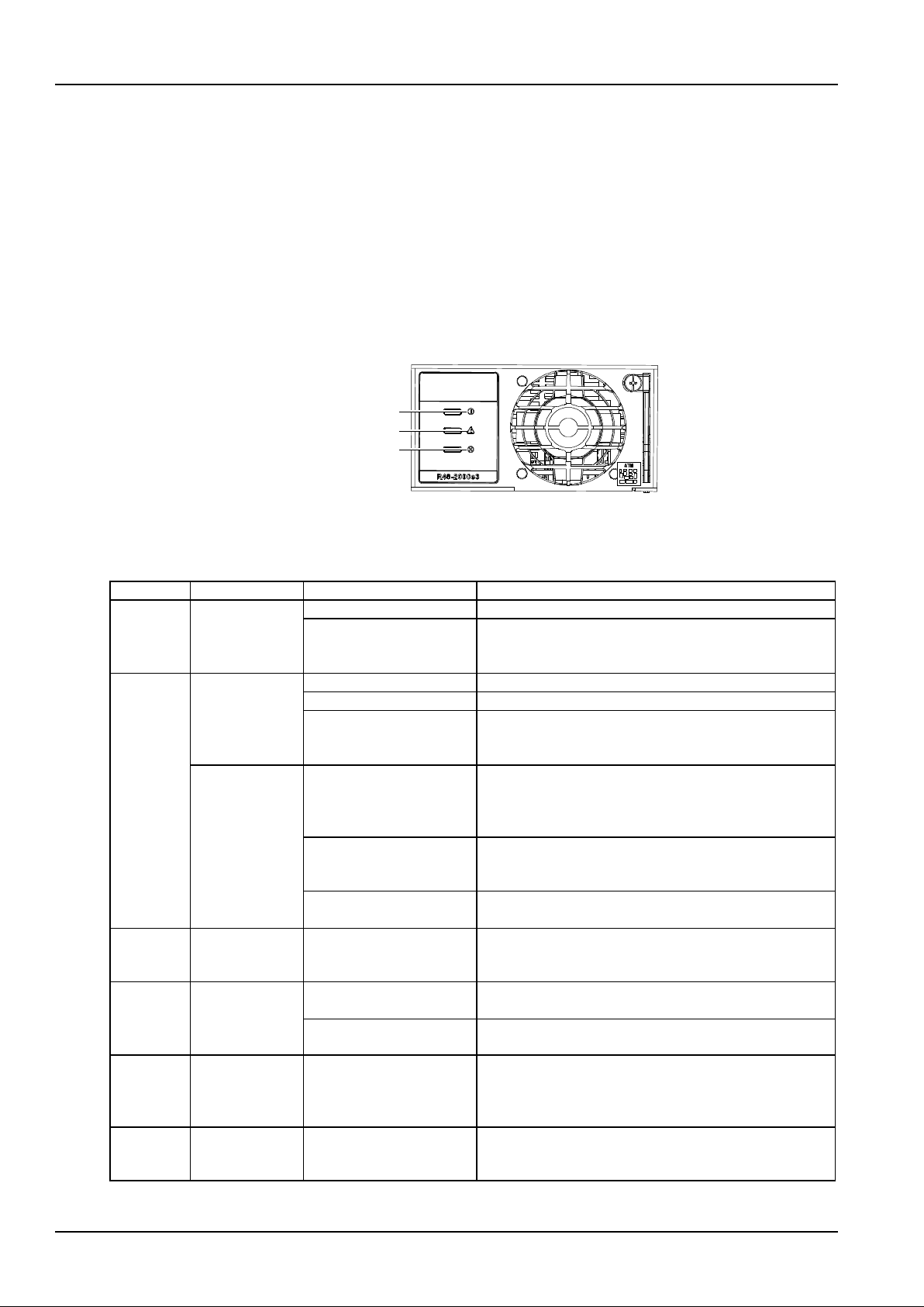
42 Chapter 5 Technical Parameters of Rectifier
NetSure 731 CC2, NetSure 731 C62 Series Power Supply System User Manual
Chapter 5 Technical Parameters of Rectifier
This chapter introduces the appearance and structure, functions and features, and technical parameters of the
rectifier.
5.1 Appearance and Structure
Front panel
The front panel of the rectifier has three indictors, as shown in Figure 5-1.
Power indicator
Protection indicator
Fault indicator
Alarm indicator
Protection indicator
Power indicator
Figure 5-1 Front panel of the rectifier
The description of the indicator function is shown in Table 5-1.
Table 5-1 Description of the indicator function
Abnormal
Alarm
Abnormal state
Suggested Action(s)
Pow er
indicator
No alarm
No input, output voltage
Restore the input, output voltage
Auxiliary power source
failure
Change the position of the abnormal rectifier and normal
rectifier, if the abnormal rectifier does not work, replace the
rectifier
Protection
indicator on
Rectifier
over-temperature
Fan rotor blocked
Remove any object that may be blocking a fan rotor.
Ventilation blocked
Remove any object that may be blocking the inlet or outlet.
Ambient temperature too
high or rectifier inlet too
close to a heat source.
Lower the ambient temperature; relocate the heat source.
Rectifier
protection
Rectifier load sharing
imbalance
Check whether the communication of the rectifier is normal, if
no, check whether the communication cable connection is
normal, if the connection is abnormal, replace the faulty
rectifier.
PFC output over/under
voltage protection
Change the position of the abnormal rectifier and normal
rectifier, if the abnormal rectifier doesnot work, replace the
rectifier
AC input out the normal
range
Correct the AC input voltage to within the acceptable range.
Protection
indicator
flashing
Rectifier
communication
failure
Communication failure
between controller and
rectifier
Check whether the communication cable connection is normal
Alarm
indicator on
Rectifier failure
Rectifier overvoltage
Pull out the rectifier and restart, if overvoltage persists,
replace the rectifier
Two or more rectifiers have
the same ID in one system
Contact Vertiv for repair
Alarm
indicator on
System current
sharing
imbalance
Rectifier severe load
sharing imbalance
Check whether the communication of the rectifier is normal, if
no, check whether the communication cable connection is
normal, if the connection is abnormal, replace the faulty
rectifier.
Alarm
indicator
flashing
Faulty rectifier
fan
Faulty rectifier fan
Replace the fan.
Page 49
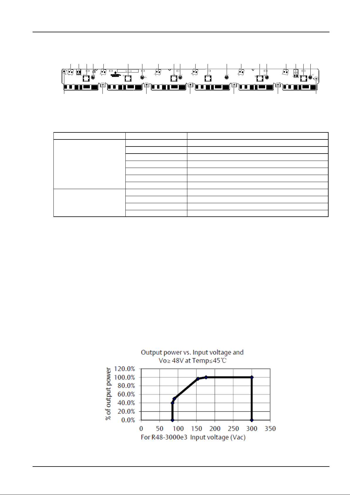
Chapter 5 Technical Parameters of Rectifier 43
NetSure 731 CC2, NetSure 731 C62 Series Power Supply System User Manual
Rear panel
There are AC input socket and DC output socket on the rear panel of the rectifier, as shown in Figure 5-2.
J6J5J4J3J2J1 J7 J8 J16 J26J14 J24J13 J23J12 J22J11 J21J15 J25
PEPEPEPEPEPEPE
Figure 5-2 Rear panel of the rectifier
Functions of the socket pins are listed in Table 5-2.
Table 5-2 Pin functions
Socket
Pin
Function
AC input socket
J1
Rectifier 1 AC input
J2
Rectifier 2 AC input
J3
Rectifier 3 AC input
J4
Rectifier 4 AC input
J5
Rectifier 5 AC input
J6
Rectifier 6 AC input
PE
Rectifier AC earthing
DC output socket
J11 ~ J16
Negative pole of the DC output
J21 ~ J26
Positive pole of the DC output
J7
CAN/matching resistance
J8
Matching resistance/CAN
5.2 Functions And Features
Hot swappable
The rectifier is hot pluggable. When the rectifier is plugged into or removed from the system which is powered on, the
system or module will not be damaged.
Active load-sharing
When the loads (60 rectifiers at most) range from 10% ~ 100%, rectifiers in the same cabinet can perform load
sharing, and maintain the average current difference of the rectifiers within ± 2A. Current sharing condition: 220V
input, 53.5V output, loads range from 10% ~ 100%.
Power limiting based on input voltage
The rectifier can output its maximum power (3000W) when the input voltage ranges from 176Vac to 305Vac. The
rectifier can work normally (but in linear power limiting mode) when the input voltage ranges from 85Vac to 176Vac.
The relationship between the output power and input voltage is shown in Figure 5-3.
Figure 5-3 Relationship between output power and input power
Page 50
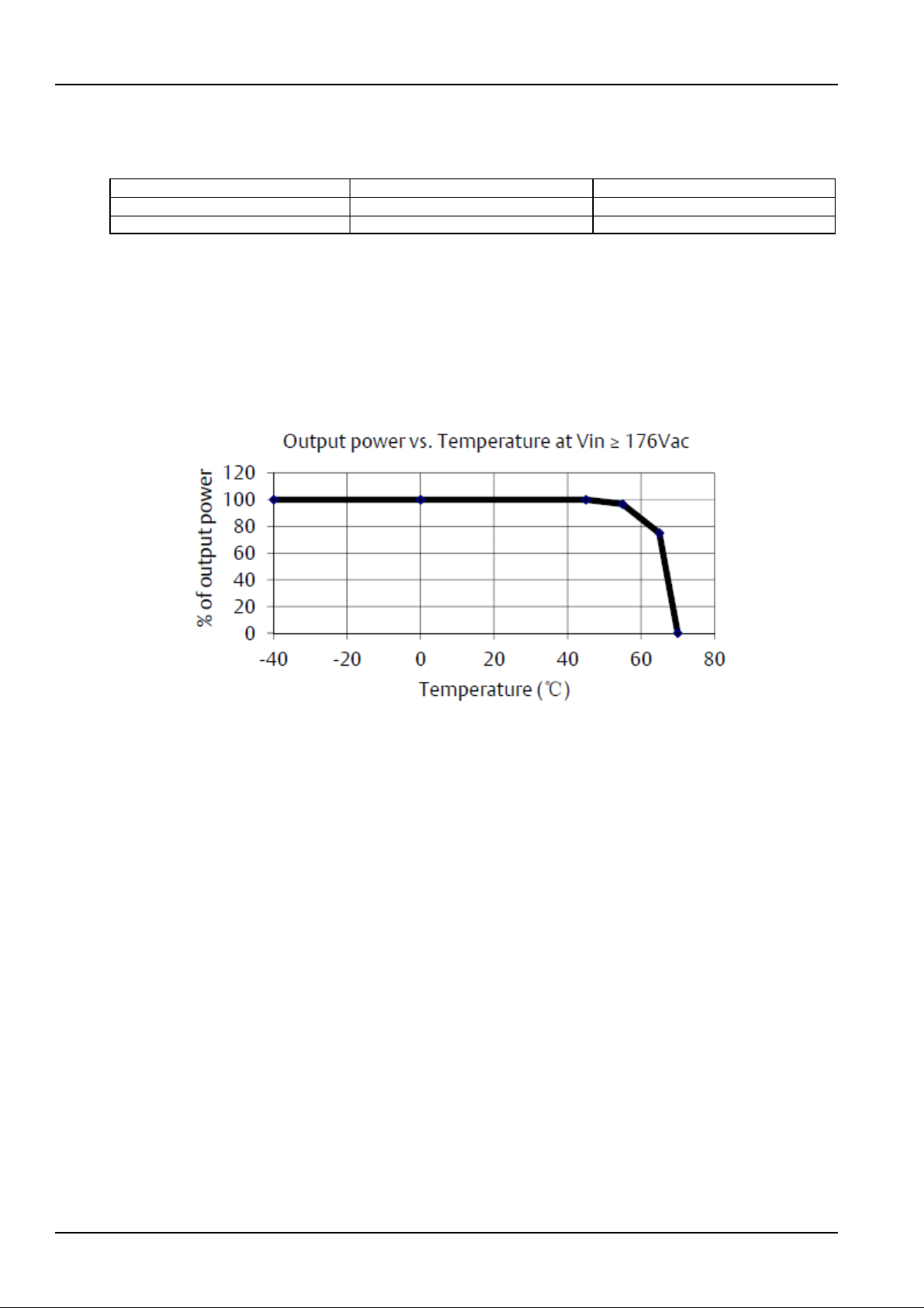
44 Chapter 5 Technical Parameters of Rectifier
NetSure 731 CC2, NetSure 731 C62 Series Power Supply System User Manual
Output characteristics
The relationship between output voltage and current is listed in Table 5-4.
Table 5-3 Output characteristics
Output power
Output current
Output voltage
3000W
51.7A
58Vdc
3000W
62.5A
48Vdc
Power limiting based on temperature
Rectifier can work in the range of -40°C to 70°C ;
The input voltage range: 176V ~ 264V;
Temperature in the range of -40°C ~ 45°C, outputs full power: 3000W;
Temperature in the range of 45°C ~ 55°C , derating from 3000W to 2900W;
Temperature in the range of 55°C ~ 65°C , derating from 2900W to 2250W;
Temperature in the range of 65°C ~ 70°C , derating from 2250W to 0W.
Figure 5-4 Output power and temperature
Output current limiting adjustment
The maximum current of the rectifier can range from 10% to 120% of the full load through the controller programming.
If the controller communication fails, the default rectifier current is 100% of the full load rated power. The full load
rectifier is defined as the maximum available current (62.5A) in the output load range. The rectifier can start as long
as connected to a fully discharged battery or capacitor bank. There is no need to run the rectifier protection device,
manual intervention is also unnecessary.
Output voltage regulation
Nominal output voltage: -48V DC, positive earthing. Adjustable within the range: -42V from -58V. User can regulate
the range through the controller, regulation precision is ± 0.1V.
Fan control
When the input voltage is in the normal range, the in-built processor will regulate the fan speed (stepless regulation)
according to the internal temperature and output power of the rectifier. For example, the fan speed increases with the
rectifier temperature or the output power. The rectifier can be set to full speed through the corresponding controller.
Input over/under voltage protection
When the input voltage is less than 80Vac, the yellow indicator will be on, and the rectifier will stop working. When the
input voltage returns to the normal range, the rectifier will automatically work in normal state. Low input voltage will
not trigger the corresponding input protection device.
When the input voltage exceeds 305Vac, the yellow indicator will be on, and the rectifier will stop working. When the
input voltage returns to the normal range, the rectifier will automatically work in normal state.
The rectifier will report the event to the controller when overvoltage protection occurs.
Page 51

Chapter 5 Technical Parameters of Rectifier 45
NetSure 731 CC2, NetSure 731 C62 Series Power Supply System User Manual
Output overvoltage protection
1. The SW overvoltage protection point can be set through the controller, the setting range is 56V ~ 59V. It should be
0.5V higher than output voltage, and the default value is 59V.
The SW overvoltage protection mode can be selected through the controller:
1) Lock out at the first overvoltage
Once the output voltage reaches software protection point, the rectifier will shut down and hold that state. it requires
manual resetting to restore the operation
2) Lock out at the second overvoltage (by default)
When the output voltage reaches the software protection point, the rectifier will shutdown, and restart automatically
after 5 seconds. If the overvoltage happens again within a set time (default: 5min. Configurable through controller),
the rectifier will shut down and hold that state. It requires manual resetting to restore the operation. If the output
current is less than 10 percent of the rated output current, the rectifier will not shut down.
Manual resetting: Resetting can be done manually through the controller, or by removing the rectifier from system
Note
If the output current is less than 10 percent of the rated output current, the rectifier will not shut down.
2. Overvoltage hardware protection: When the output voltage (unadjustable) reaches the hardware protection point
(58.5V ~ 60V), the rectifier will shutdown, and restart automatically after 5 seconds. If the overvoltage happens again
within a set time (default: 5min. configurable through controller), the rectifier will shut down and hold that state. It
requires manual resetting to restore the operation.
Overtemperature protection
Power limiting based on temperature
Each rectifier monitors the working temperature of the power-switching circuit. No matter in what reason (for instance,
high ambient temperature or fan fault) the temperature increase + 35C, the rectifier will not power off. But it will limit
the maximum power output, and then turn into the power limiting status to guarantee the power-switching circuit
temperature is in the setting range. The operation at temperature from +35C to +70C will minimize the output power.
When the temperature dropped to about +35C, the full power will restore.
Page 52

46 Chapter 5 Technical Parameters of Rectifier
NetSure 731 CC2, NetSure 731 C62 Series Power Supply System User Manual
Warning
The continuous running rated full power output temperature of the rectifier reaches up to +35C full power. The operation at the
temperature from +35C to +70C will minimize the output power. The operation at temperature above +70C is abnormal, the
running is temporary1.
1Temporary running at abnormal temperature: The continuous running time for temporary running in one day cannot exceed 8
hours, in one year cannot exceed 15 days (that is, it cannot exceed 120 hours in one year, the frequency cannot exceed 15 days).
PFC over/under voltage
If the inner bus voltage value exceeds the over/under voltage threshold, the rectifier would be shut down, and the
yellow indicator would be on.
Communication failure
The yellow indicator on the rectifier panel will flash when the rectifier experiences a communication failure. To protect
the battery, when the rectifier communication failure occurs, the rectifier output voltage will automatically adjust to
53.5V (according to actual need, different voltages can be preset). The yellow indicator on the rectifier panel will be
normal when the rectifier communication is restored. Auto-recovery is enabled upon the clearing of the corresponding
fault.
Fan fault protection
An alarm will be generated upon a fan fault. In such cases, the red indicator on the rectifier panel will flash, the
rectifier will be off, no voltage output. Auto-recovery is enabled upon the clearing of the corresponding fault.
Imbalance output current
When there are multiple rectifiers in the power system, the rectifier with high load sharing error will be recognized
automatically, and the yellow indicator on the panel will be on.
The failure information will be reported to the associated system controller and the controller will process the failure accordingly.
Monitoring function
There’s a built-in digital signal processor in the rectifier. The processor monitors and controls the rectifier operation,
and communicates with the controller in real time through the CAN bus. Table 5-5 lists the exchanged commands
and information between the rectifier and controller.
Table 5-4 Exchanged information between the rectifier and controller
Receiving command and
signal of the rectifier
Pow er on / Off, current marching technique on / off, overvoltage shutdown reset, current limiting
regulation, voltage regulation
Controller information
reported by the rectifier
Input voltage, output voltage, output current, current limiting setting, temperature, overvoltage
setting, pow er on / off status, fault alarm (overvoltage shutdown, fan fault), protection
information (input voltage protection, internal busbar voltage protection, high temperature
protection), high temperature derating, input derating, input power failure, output current not
sharing, address, code, date, software version, hardware version
5.3 Technical Parameters
Table 5-5 Technical parameters of the rectifier
Parameters
Name
Description
Environmental
Operating temperature
-5C ~ 40C (derating is necessary above 35C, startup in -40C)
Relative humidity
≤ 95% , non-condensing
Altitude
≤ 2000m, derating is necessary above 2,000m
Cooling mode
Forced cooling
AC input
Input system
1-phase 3-wire
Voltage range
85Vac ~ 305Vac
Rated voltage
200Vac ~ 240Vac
Max. static voltage upon no
operation
415Vac
Input current
< 22A
Impact current upon startup
< 31A
Page 53

Chapter 5 Technical Parameters of Rectifier 47
NetSure 731 CC2, NetSure 731 C62 Series Power Supply System User Manual
Parameters
Name
Description
AC input
Input impact current
< 150% steady state input peak current
Allowable grid frequency
45Hz ~ 65Hz
Rated grid frequency
50Hz/ 60Hz
DC output
Voltage range
42V ~ 58V
DC current
0 ~ 62.5A
Total regulation
≤ ±0.6%
Load regulation
≤ ±0.5%
Voltage regulation
≤ ±0.1%
Startup impact range
≤ ±1%
Mechanical
parameters
Dimension
43.6mm (H) × 85.1mm (W) × 330mm (D)
Weight
≤ 3kg
Page 54

48 Chapter 6 Troubleshooting
NetSure 731 CC2, NetSure 731 C62 Series Power Supply System User Manual
Chapter 6 Troubleshooting
This chapter describes the alarm handling and maintenance of the power system. The maintenance personnel must
have adequate knowledge about the power system.
Note
1. The maintenance must be conducted under the guidance of related safety regulations.
2. Only trained personnel with adequate knowledge about the power system shall maintain the inner part of the cabinet.
6.1 Handling Alarms
The controller alarms are classified into four types: critical alarm, major alarm, observation and no alarm. The
phenomenon and description of the alarm are shown in Table 6-1.
Table 6-1 Alarm description and phenomenon
Alarm level
Description
Phenomenon
Critical alarm,
major alarm
These tw o types of alarms have strong impacts on the system performance.
Whenever these alarms are generated, users are supposed to handle them
immediately
The alarm indicator of the
controller w ill be on and
audible alarm will be
given
Observation
When this type of alarm is raised, the power system maintains normal output for
a while. If the alarm occurs during w atch time, it should be handled immediately.
If the alarm occurs during non-watch time, it should be handled during watch time
Only the alarm indicator
of the controller will be on
No alarm
If alarms are set as ‘no alarm’ by users, when these alarms occur, no visual or
audible indication will be generated and the power system works normally
None
The handling methods of common alarms are given in Table 6-2.
Table 6-2 Handling methods of common alarms
No.
Alarm
Handling method
1
Mains Failure
If the failure does not last long, the battery will power the load. If the cause is unknown or the failure
lasts too long, a diesel generator is needed. Before using the generator power to supply the power
system, it is suggested to run the generator five minutes to minimize the impact on the power system
2
AC Voltage High
Check if the AC over-voltage value is too low. If yes, change the value.
A mild over-voltage does not affect the system operation. However, the rectifier will stop operation
when the mains voltage is more than 530V. If the mains voltage is above the AC over-voltage value,
the mains grid should be improved
3
AC Voltage Low
Check if the AC Under- voltage point is too high. If yes, change the value.
When the mains voltage is lower than 304V, the output power of the rectifiers will be derated. And if
lower than 260V, the rectifiers will stop working. If the mains voltage is under the AC under-voltage
value, the mains grid should be improved
4
SPD failure
Check the SPD condition. If the SPD is damaged, replace it
5
DC Volt High
Check the DC over-voltage value through the controller. If the set value is inappropriate, correct it.
Otherwise, find out the rectifier that has caused the alarm:
1. Ensure that the batteries can operate normally.
2. Switch off the AC input of all rectifiers.
3. Pow er on the rectifiers one by one.
4. If the over-voltage protection is triggered when a certain rectifier is powered on, that rectifier is the
faulty one. Replace it
6
DC Volt Low
1. Check if the alarm is caused by mains failure, if yes, disconnect some loads to prolong the
operation of the whole system.
2. Check the DC under-voltage value set through the controller. If the set value is inappropriate,
correct it.
3. Check if any rectifier is inoperative, or has no output current. If yes, replace it.
4. Check if the total load current exceeds the total rectifier current during float charge. If yes,
disconnect some loads or add more rectifiers to make the total rectifier current bigger than 120% of
the total load current with one redundant rectifier
Page 55
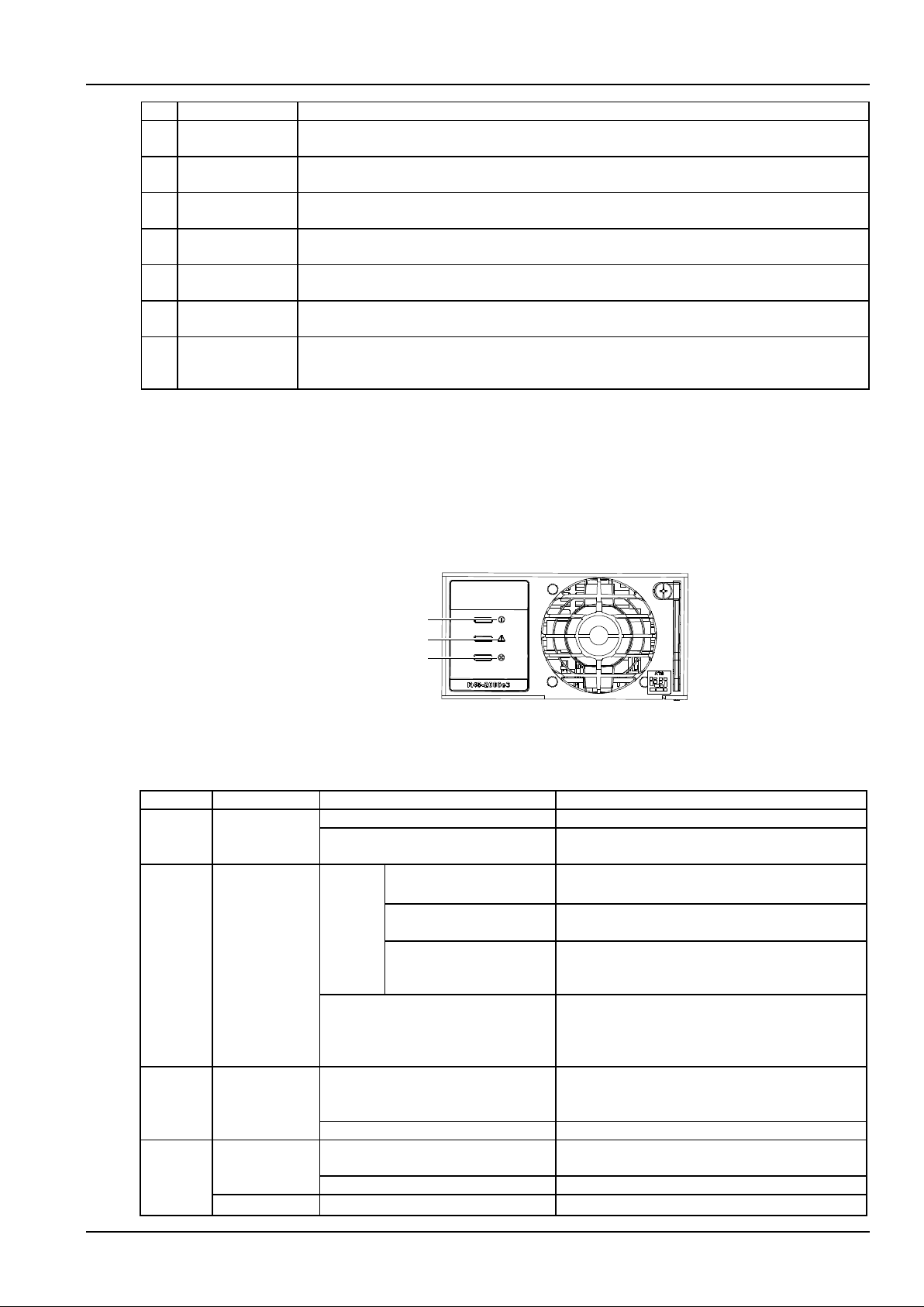
Chapter 6 Troubleshooting 49
NetSure 731 CC2, NetSure 731 C62 Series Power Supply System User Manual
No.
Alarm
Handling method
7
Load Fuse Alarm,
Batt Fuse Alarm
Check if the corresponding MCB is sw itched off. If the MCB is open, find out the fault and remove it.
Otherwise, the alarm circuit is faulty. Please contact Vertiv
8
LVD2
1. Check if there is mains failure, and the battery voltage is lower than the value of ‘LVD2’.
2. Check whether the battery is disconnected from the system manually
9
Rect Failure
The rectifier with the fault indicator (red) on is faulty.
Pow er off the rectifier, and then pow er it on after a while. If the alarm persists, replace the rectifier
10
Rect Protect
Check if the mains voltage is above 530V or under 260V. If the mains voltage is under the AC
under-voltage value or above the AC over-voltage value, the mains grid should be improved
11
Rect Fan Fails
Pull out the rectifier to check if the fan is obstructed. If yes, clean it and push the rectifier back. If the
fan is not obstructed or if the fault persists after cleaning, replace the fan
12
Rect Not Respond
Check if the communication cable is connected properly between rectifier and controller. If yes,
restart the rectifier. If the alarm persists, replace the rectifier
13
Batt Over Temp
1. Check if the battery compartment temperature is too high. If yes, cool down the battery
compartment.
2. Check if there is battery internal fault. If yes, replace the faulty battery
6.2 Handling Rectifier Fault
Fault judgement and handling method
Rectifier faults include power indicator (green) off, protection indicator (yellow) on, protection indicator (yellow)
flashing, fault indicator (red) on and fault indicator (red) flashing.
The indicators are shown in Figure 6-1.
Power indicator
Protection indicator
Fault indicator
Figure 6-1 Rectifier indicator
The methods to handle the fault of the rectifier are listed in Table 6-3.
Table 6-3 Methods to handle the fault of the rectifier
Symptom
Controller alarms
Causes
Handling method
Green
indicator
off
No alarm
No input/output voltage
Restore input voltage
Input fuse broken
Replace the rectifier
Yellow
indicator
on
Rect Protect
Overtemperat
ure
protection
due to:
Fan blocked
Remove the object that blocks the fan
Ventilation path blocked at
the inlet or vent
Remove the object at the inlet or vent
Ambient temperature too
high or the inlet too close to a
heat source
Decrease the ambient temperature or remove the heat
source
Load sharing imbalance
Check whether the rectifier communication is normal.
If not, check w hether the communication cable is in
normal connection. If the communication is normal
while the protection indicator is on, replace the rectifier
Yellow
indicator
on
Rect Protect
PFC output overvoltage protection
Change the position of the normal rectifier and faulty
rectifier. If the faulty rectifier cannot working, replace
the rectifier
AC input voltage abnormal
Make sure that the AC input voltage is normal
Red
indictor on
Rect Failure
Rectifier overvoltage
Pull out the rectifier. If the protection is triggered again,
replace the rectifier
Inner fuse broken
Contact Vertiv for maintenance
System bad
Serious load sharing imbalance
Check whether the rectifier communication is normal.
Page 56
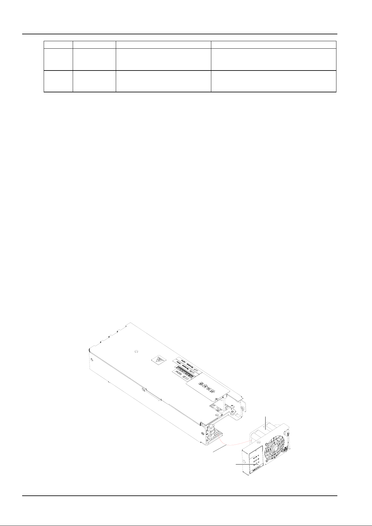
50 Chapter 6 Troubleshooting
NetSure 731 CC2, NetSure 731 C62 Series Power Supply System User Manual
Symptom
Controller alarms
Causes
Handling method
Red
indictor on
current
imbalance
Serious load sharing imbalance
If not, check w hether the communication cable is in
normal connection. If the communication is normal
while the protection indicator is on, replace the rectifier
Red
indicator
blinks
Rect Fan Fails
Fan fault
Replace the fan
Replacing rectifier fan
If the rectifier fan is faulty, use the following procedures to replace the fan:
1. Performing this procedure may activate external system alarms. Do one of the following. If possible, disable these
alarms. If these alarms cannot be easily disabled, notify the appropriate personnel to disregard any future alarms
associated with this system.
2. Remove the rectifier from the shelf. Refer to the related procedure for step-by-step instructions.
3. Place the rectifier on a static-safe work surface. Connect an approved grounding strap to your wrist for the
remainder of this procedure.
4. Remove the two faceplate mounting screws shown in Figure 5-2 from the Rectifier Module. Remove the faceplate.
5. Carefully pull the fan(s) out from the rectifier, until the fan power cable(s) can be accessed.
6. Unplug the fan power cable(s) from connector(s) on the PC board, and remove the fan(s).
7. Plug the power cable(s) of the replacement fan(s) into the connector(s) on the PC board.
8. Place each fan in its cavity in the module, orienting the fan so that:
The arrow on the fan body points toward the rear of the Rectifier Module, and
The power cable exits the fan body toward the other fan, as shown in Figure 6-2.
9. Reinstall the faceplate on the rectifier. Ensure that no fan wiring is pinched. Secure faceplate with the two
previously removed screws.
10. Reinstall the rectifier into the shelf as described in the previous procedure.
11. When the fans start, check to ensure that each is providing front-to-back airflow. If air direction is wrong,
immediately remove the rectifier from the shelf. Repeat previous steps to check fan orientation, and correct as
necessary. Reinstall the rectifier and again check for proper airflow.
12. Enable the external alarms, or notify appropriate personnel that this procedure is finished.
13. Ensure that there are no local or remote alarms active on the system.
Panel
Fan
Power cable
Figure 6-2 Rectifier fan replacement
Page 57
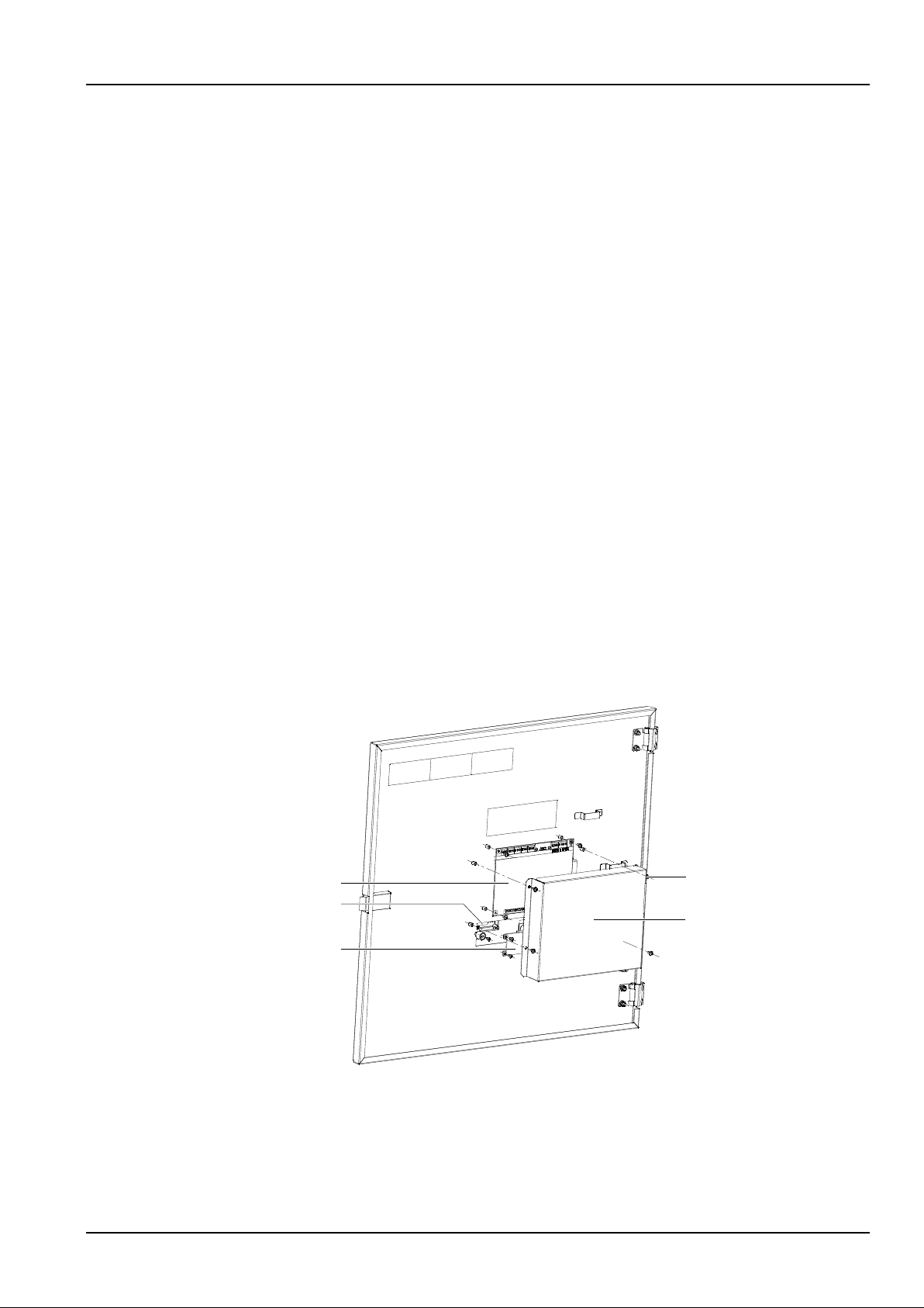
Chapter 6 Troubleshooting 51
NetSure 731 CC2, NetSure 731 C62 Series Power Supply System User Manual
Rectifier replacement
Other than a rectifier fan replacement, no attempt should be made to troubleshoot or repair individual components on
any rectifier. You should take the following procedures when a rectifier is faulty.
1. Refer to Figure 5-2Figure 6-2 during this procedure.
2. Performing this procedure may activate external system alarms. Do one of the following. If possible, disable these
alarms. If these alarms cannot be easily disabled, notify the appropriate personnel to disregard any future alarms
associated with this system.
3. On the module being replaced, loosen the screw that is located on the module handle. (Turn the screw several
turns counterclockwise to loosen.) Pivot the handle 90 degrees to the open position.
4. Grasp the handle and pull firmly to remove the module from the shelf.
5. On the replacement module, loosen the screw that is located on the module handle. (Turn the screw several turns
counterclockwise to loosen.) Pivot the handle 90 degrees to the open position.
6. Place the module into the mounting position in the shelf, and with the handle still in the open position, push the
module completely into the shelf.
7. Push the handle into the front panel of the module. This will lock the module securely in the shelf. Tighten the
screw on the handle.
8. Reset the system controller as required.
9. Enable the external system alarms, or notify appropriate personnel that this procedure is finished.
10. Ensure that there are no local or remote alarms active on the system.
6.3 Handling Controller Fault
Fault judgement
The fault phenomena of the controller are LCD failure or displayed contents incorrect. You should take the following
procedures to judge fault causes:
1. Loosen the three fixing screws on the PCB cover and remove the cover, as shown in Figure 6-3.
Cover of the PCB board
Fixing screw of the
cover
PCB board
Front panel of the controller
LCD
PCB
PCB cover
Figure 6-3 Removing cover
Page 58
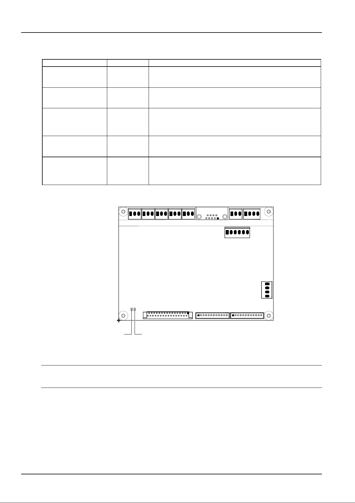
52 Chapter 6 Troubleshooting
NetSure 731 CC2, NetSure 731 C62 Series Power Supply System User Manual
2. Judge fault causes according to the indicator status of the PCB, as listed in Table 6-4.
Table 6-4 Fault causes and handling methods of the controller
Phenomenon
Fault cause
Handling method
Watchdog indicator off,
power indicator off
PCB has no
auxiliary power
supply
Check if J8 terminal on PCB is connected reliably. If the connection is reliable
and the terminal voltage is normal (approximately the busbar voltage of the
power system), the PCB is faulty and needs replacement
Pow er indicator on,
watchdog indicator on or
off
Softw are not
running
Replace the PCB
Watchdog indicator
flashing, LCD display
incorrect
Signal cable
connection
incorrect or PCB
faulty
Check if the signal cable connection is correct and reliable. If not, reconnect it.
If yes, the PCB is faulty and needs replacement
Watchdog indicator
flashing, LCD no display
PCB faulty or
LCD faulty
Replace the LCD according to Replacing the LCD in this section. Check if
the LCD displays normally. If yes, the fault handling is over. If not, the PCB is
faulty and needs replacement
Pow er indicator on,
watchdog indicator on or
off, LCD displaying
‘Bootloader is Running’
Softw are is
updating about
firmw are
The controller w ill switch back to main program automatically after five
minutes. If not, the application has not been w ritten successfully or has been
destroyed. You need to write the application again. If still not, the CPU is
damaged
The indicators and terminals of the PCB are shown in Figure 6-4.
J6
B
2
31
32
1
1
5
9
6
J1 J2
J3
J4 J5
J7
J8
J9
J10
J12J11
RS232
Temp
LCD
Power indicator Watchdog indicator
Figure 6-4 Indicators and terminals of the PCB
Replacing the PCB
Note
Take care when replacing components of the controller. During replacement, unplug the terminals strictly in the order shown in
the following procedures, failure to observe this may result in system shutdown.
The procedures for replacing PCB are described as follows:
1. Unplug the J8 power supply terminal to power off the PCB.
2. Unplug other terminals and DI/DO cables.
3. Wrap the DI/DO cable terminals with insulating tape. To prevent short circuit, keep the disconnected terminals and
cables insulated from components of the power system and the PCB.
4. Remove the fixing screws of the PCB and replace the PCB. Note that the screwdriver should be prevented from
touching the bare parts of the signal cables to prevent short circuit.
Page 59

Chapter 6 Troubleshooting 53
NetSure 731 CC2, NetSure 731 C62 Series Power Supply System User Manual
5. Connect the signal cables in reverse sequence, that is, reconnect signal cables other than J8, J10 terminal cables
and DI/DO cables.
6. Check the cable connections. If the connections are correct, reconnect J8 terminal. If the watchdog indicator
flashes and power indicator is on, the PCB works normally.
7. Check the voltages of J10 terminal with a multimeter. Make sure that it outputs low voltage. Connect J10 terminal.
8. Set the parameters of the controller according to Chapter 4.7 Setting Parameters.
Replacing the LCD
The procedures for replacing the LCD are described as follows:
1. Unplug J8 and J10 terminals of the PCB.
2. Unplug the terminal tape cable connected the LCD and screen.
3. Replace the LCD. Restore the J3 terminal tape cable connected the LCD and screen. Pay attention not to short the
LCD with the power system or the PCB.
4. Check the voltages of J10 terminal with a multimeter. Make sure that it outputs low voltage.
5. Insert the J10 terminal, and the LCD is replaced.
6. Insert the J8 terminal to power on the PCB of the controller.
Page 60
54 Appendix 1 Technical Data
NetSure 731 CC2, NetSure 731 C62 Series Power Supply System User Manual
Appendix 1 Technical Data
Table 1 Technical data
Parameter
category
Parameter
Description
Environmental
Operating
temperature
-5°C ~ +40°C
Storage temperature
-40°C ~ +70°C
Relative humidity
5%RH ~ 95%RH
Altitude
≤ 2000m (derating is necessary above 2,000m)
Overvoltage level
Level II
Pollution level
Level II
Others
No conductive dust or erosive gases. No possibility of explosion
AC input
AC input system
3-phase 4-wire system, 3-phase 5-wire system, TN, TT
Rated input phase
voltage
220Vac
Input voltage range
85Vac ~ 300Vac, output derating under 176Vac
Input AC voltage
frequency
45Hz ~ 65Hz
Max input current
NetSure 731 C62 ≤ 37A (176V input); NetSure 731 CC2 ≤ 74A (176V input)
Pow er factor
≥ 0.99
DC output
Output DC voltage
42.3Vdc ~ 57.6Vdc
Output DC current
NetSure 731 C62: load current ≤ 200A, battery charge current ≤ 100A
NetSure 731 CC2: load current ≤400A, battery charge current ≤ 200A
Total regulation
≤ 1%
Efficiency
≥ 94.2%
Noise (peak-peak)
≤ 200mV (0 ~ 20MHz)
Weighted noise
≤ 2mV (300Hz ~ 3400Hz)
Wide frequency
noise
≤ 50mV (3.4kHz ~ 150kHz), ≤ 20mV (150kHz ~ 30MHz)
Discrete noise
≤ 5mV (3.4 kHz ~ 150kHz), ≤ 3mV (150kHz ~ 200kHz), ≤ 2mV (200kHz ~ 500kHz),
≤ 1mV (0.5MHz ~ 30MHz)
AC input
alarm and
protection
AC input overvoltage
alarm point
Default: 280Vac ± 5Vac, configurable through controller
AC input overvoltage
recovery point
Default: 270Vac ± 5Vac, 10Vac lower than the AC input overvoltage alarm point
AC input
undervoltage alarm
point
Default: 180Vac ± 5Vac, configurable through controller
AC input
undervoltage
recovery point
Default: 190Vac ± 5Vac, 10Vac higher than the AC input undervoltage alarm point
AC input overvoltage
protection point
Default 305Vac ± 5Vac, configurable through controller
AC input overvoltage
protection recovery
point
10Vac lower than the AC input overvoltage protection point
AC input
undervoltage
protection point
Default: 80Vac ± 5Vac, configurable through controller
AC input
undervoltage
protection recovery
point
15Vac higher than the AC input undervoltage alarm point
Page 61
Appendix 1 Technical Data 55
NetSure 731 CC2, NetSure 731 C62 Series Power Supply System User Manual
Parameter
category
Parameter
Description
DC output
alarm and
protection
DC output
overvoltage alarm
point
Default: 58.5Vdc ± 0.2Vdc, configurable through controller
DC output
overvoltage recovery
point
Default: 58.0Vdc ± 0.2Vdc, 0.5Vdc lower than the overvoltage alarm point
DC output
undervoltage alarm
point
Default: 45.0Vdc ± 0.2Vdc, configurable through controller
DC output
undervoltage
recovery point
Default: 45.5Vdc ± 0.2Vdc, 0.5Vdc higher than the undervoltage alarm point
LLVD point
Default: 44.0Vdc ± 0.2Vdc, configurable through controller
BLVD point
Default: 43.2Vdc ± 0.2Vdc, configurable through controller
Rectifier
Load sharing
The rectifiers can w ork in parallel and share the current. The unbalance is better than
± 3% rated output current. Test current range: 10% ~ 100% rated current
Derate by input (at
45°C )
176Vac~300Vac input, maximum rectifier output pow er is100% rated power (3000W);
85Vac input, maximum rectifier output power is20% rated power
Slow output start
function
Upon rectifier power-on, the output voltage increases slowly, and the rise time can be
set
Fan speed can be
set
The rectifier fan speed can be set to be regulated automatically. It can also be set to
full speed
Overvoltage
protection
The rectifier provides overvoltage hardware and software protection. The hardware
protection point is 59.5V ± 0.5V, and it requires manual resetting to restore operation.
The software protection point is between 56V and 59V (0.5V above output voltage,
59V by default), and can be set through the controller
There are two software protection modes, which can be selected through the software
at the host:
1. Lock out at the first overvoltage
Once the output voltage reaches software protection point, the rectifier will shut down
and hold that state. it requires manual resetting to restore the operation
2. Lock out at the second overvoltage
When the output voltage reaches the software protection point, the rectifier will
shutdown, and restart automatically after 5 seconds. If the overvoltage happens again
within a set time (default: 5min. Configurable through controller), the rectifier will shut
down and hold that state. It requires manual resetting to restore the operation
Manual resetting: Resetting can be done manually through the controller, or by
removing the rectifier from system
Temperature
derating
Rectifier can w ork in temperature below -40°C ;
Temperature below 45°C , outputs full power: 3000W;
Temperature in the range of 45°C ~ 55°C , derating from 3000W to 2900W;
Temperature in the range of 55°C ~ 65°C , derating from 2900W to 2250W;
Temperature in the range of 65°C ~ 70°C , derating from 2250W to 0W
EMC
EFT
Level 4 EN61000-4-4
ESD
Level 3 EN61000-4-2
Immunity to surges
Level 4 EN61000-4-5
Lightning
protection
features
At AC side
The AC input side can w ithstand five times of simulated lightning voltage of 5kV at
10/700µs, for the positive and negative polarities respectively. It can w ithstand five
times of simulated lightning voltage of 20kV at 8/20µs, for the positive and negative
polarities respectively. It can also withstand one time of simulated lightning surge
current of 40kA at 8/20µs. The test interval is not smaller than 1 minute.
At DC side
The DC side can withstand one event of simulated lightning current of 15kA at 8/20µs
Page 62
56 Appendix 1 Technical Data
NetSure 731 CC2, NetSure 731 C62 Series Power Supply System User Manual
Parameter
category
Parameter
Description
Others
Safety regulation
EN60950
Noise
≤ 60dB (A) (When the ambient temperature is 30°C )
Insulation resistance
At temperature of 15°C ~ 35°C and relative humidity not bigger than 90%RH, apply a
test voltage of 500Vdc, the insulation resistances between AC circuit and earth, DC
circuit and earth, and AC and DC circuits are all not less than 10MΩ
Insulation strength
(Remove the SPD, controller and rectifiers from the power system before the test.)
AC circuit to DC circuit: 50Hz, 3000Vac
AC circuit to earth: 50Hz, 1500Vac
Other
Insulation strength
DC circuit to earth: 50Hz, 500Vac
For all the three tests above, there should be no breakdown or flashover within 1min,
with leakage current not bigger than 10mA
MTBF
200000hr
Mechanical
Dimensions (mm)
Cabinet
600 (W) × 400 (D) × 1600 (H) (NetSure 731 C62-X1/X3,
NetSure 731 CC2-X1\X2\X3\X4)
600 (W) × 600 (D) × 1600 (H) (NetSure 731 C62-X2)
Rectifier
43.6 (H) × 85.1 (W) × 330 (D)
Weight (kg)
Cabinet (including
rectifiers)
NetSure 731 C62 ≤ 100
NetSure 731 CC2 ≤ 110
Rectifier
≤ 3.0
Page 63
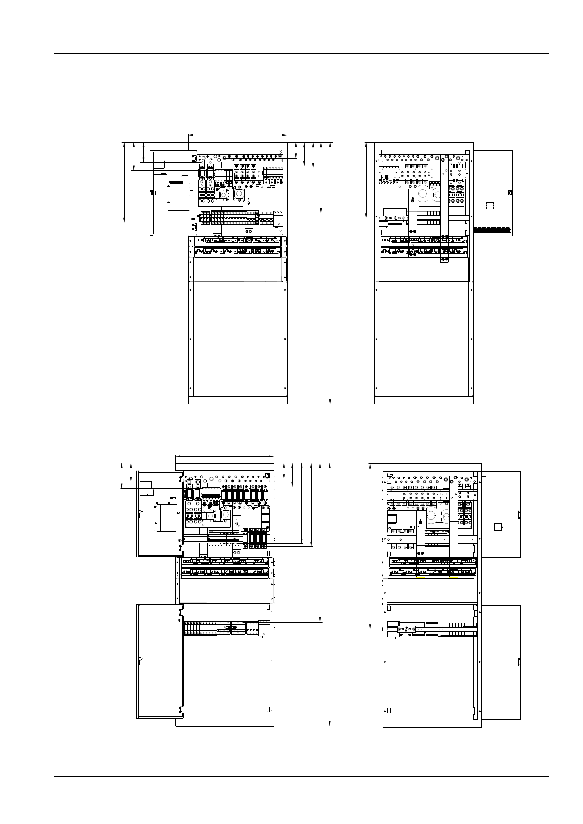
Appendix 2 Engineering Diagram 57
NetSure 731 CC2, NetSure 731 C62 Series Power Supply System User Manual
Appendix 2 Engineering Diagram
600
123
171
493
98
145
155
432
1600
464
Front view Rear view
Figure 1 NetSure 731 CC2-X3/X4 engineering diagram (unit: mm)
600
117
155
98
145
491
508
970
1600
1004
Front view Rear view
Figure 2 NetSure 731 CC2-X1/X2 engineering diagram (unit: mm)
Page 64
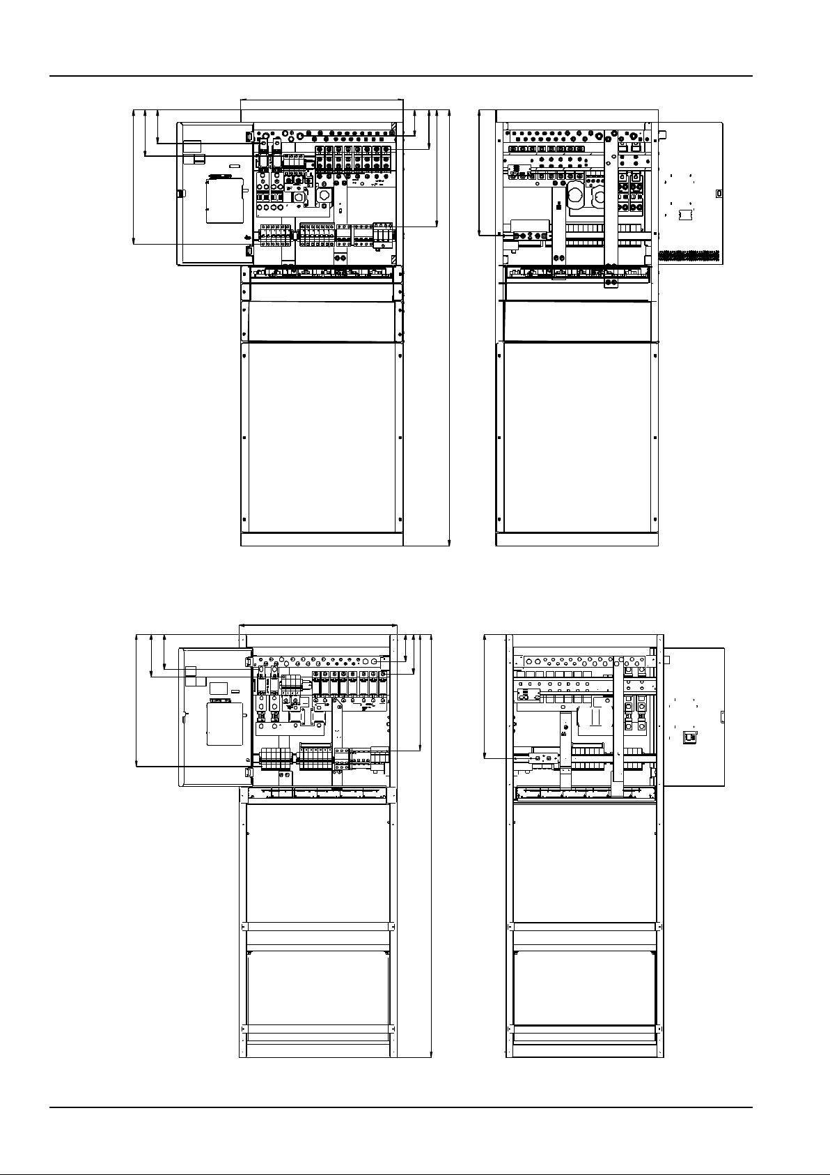
58 Appendix 2 Engineering Diagram
NetSure 731 CC2, NetSure 731 C62 Series Power Supply System User Manual
493
171
123
1600
600
98
144
429
464
Front view Rear view
Figure 3 NetSure 731 C62-X1 engineering diagram (unit: mm)
500
160
132
600
440
150
103
1600
469
Figure 4 NetSure 731 C62-X2 engineering diagram (unit: mm)
Page 65
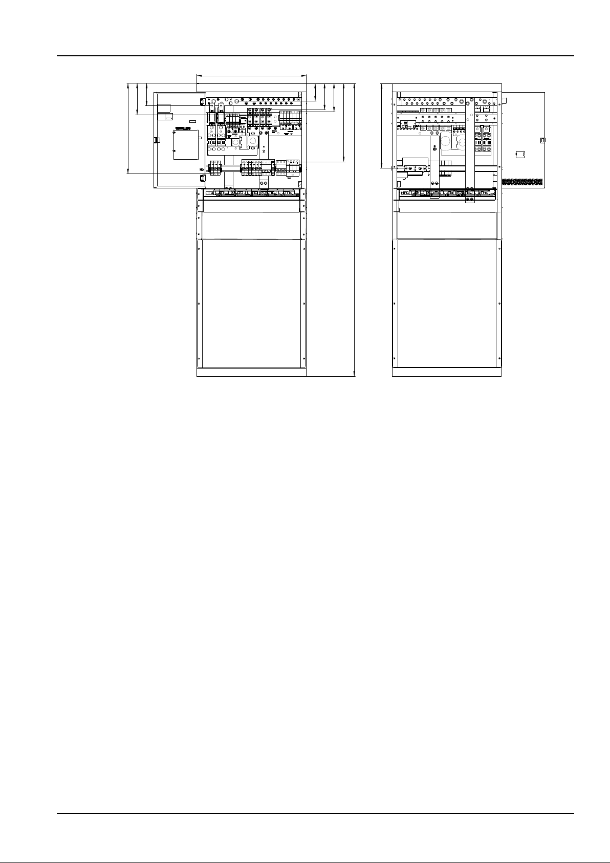
Appendix 2 Engineering Diagram 59
NetSure 731 CC2, NetSure 731 C62 Series Power Supply System User Manual
600
123
171
98
144
155
429
1600
493
464
Figure 5 NetSure 731 C62-X3 engineering diagram (unit: mm)
Page 66

60 Appendix 2 Engineering Diagram
NetSure 731 CC2, NetSure 731 C62 Series Power Supply System User Manual
Table 2 System engineering data
Connector
Specs
Connection
Capacity
Connector specs
AC
distribution
AC input
MCB1
1 × 100A/3P or 1 × 63A/3P
3 H-shape cable terminals,
CSA ≤ 35mm2
The live line of AC power supply
Grounding
busbar
One M10 bolt
CSA ≤ 35mm2
Connected to the earth bar of the
equipment room
Input neutral
terminal
2 bolts
CSA ≤ 25mm2
Neutral line of AC power supply
Output neutral
busbar
2 M6 bolts
Neutral terminal of the AC output
power, serving other equipment
AC output
MCB2
1 × 16A/ 3P, 1 × 16A/ 1P
4 H-shape cable terminals,
CSA ≤ 10mm2
Live terminal of the AC output
power, serving other equipment
DC
distribution
Positive
busbar
2 × M12 (for battery connection), 4 × M8, 14 × M6
Battery fuse
NetSure 731 CC2-X1/X2/X3/X4: 2 × 500A fuse, 2 × M12 fuse bolt
NetSure 731 C62-X1/X2/X3: 2 × 250A fuse, 2 × M10 fuse bolt
Load route
NetSure 731 C62-X1:
Battery protection routes: 2 × 32A/1P, 2 × 10A/1P MCB;
LLVD routes: 4 × 100A fuse, 4 × 63A fuse, 4 × 32A/1P MCB, 2 × 10A/1P MCB;
NetSure 731 C62-X2:
Battery protection routes: 2 × 32A/1P, 2 × 10A/1P MCB;
LLVD routes: 4 × 100A fuse, 4 × 63A fuse, 4 × 32A/1P MCB, 2 × 10A/1P MCB;
NetSure 731 C62-X3:
Battery protection routes: 2 × 32A/1P, 2 × 16A/1P MCB;
LLVD routes: 4 × 100A fuse, 4 × 63A/1P MCB, 6 × 32A/1P MCB;
NetSure 731 CC2-X1/X2:
Battery protection routes: 2 × 32A/1P, 4 × 10A/1P MCB;
LLVD routes: 6 × 100A fuse, 6 × 63A fuse, 6× 32A/1P, 4 × 16A/1P MCB;
NetSure 731 CC2-X3:
Battery protection routes: 4 × 16A/1P MCB;
LLVD routes: 4 × 100A fuse, 4 × 63A/1P, 6 × 32A/1P MCB;
NetSure 731 CC2-X4:
Battery protection routes: 2 × 63A/1P, 2 × 32A/1P, 2 × 10A/1P MCB;
LLVD routes: 4 × 100A, 6 × 63A fuse, 2 × 32A/1P, 2 × 16A/1P MCB
Note: NetSure 731 C62-X1/X3, NetSure 731 CC2-X1 & NetSure 731 CC2-X3 & NetSure 731 CC2-X4 have single AC input;
NetSure 731 CC2-X2 has double AC inputs; NetSure 731 C62-X2 have single AC input, The cabinet is equipped with tw o battery
racks
Page 67
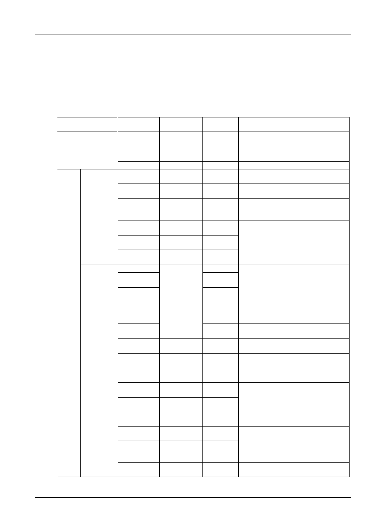
Appendix 3 Parameter Setting Of The Controller 61
NetSure 731 CC2, NetSure 731 C62 Series Power Supply System User Manual
Appendix 3 Parameter Setting Of The Controller
This chapter gives the description of the controller parameter setting. The detailed information of parameter setting
and operating method are given in Chapter 4 Use Of The Controller. See 4.7.1 Alarm Settings for alarm setting
method.
Table 3 Parameter setting of the controller
Item
Parameter
Range
Factory
setting
Value description
Alarm
DI No.
1 ~ 8
1
The 8 corresponding connecting terminals,
queued up in the order that the hardware
sw itches are put
DI Name
-
SPD
Figures or letters, 10 at most
Alarm Mode
High, Low
Low
Alarm upon high level or upon low level
Battery
Basic
Sys Mode
Auto, Manual
Auto
Managing the power system through the
controller or manually
Bat. Fuse
0 ~ 2
2
You should set this parameter according to the
actual battery configuration
Capacity
50Ah ~ 5000Ah
300Ah
The capacity of each battery strings. You
should set this parameter according to the
actual battery configuration
Bat. Shunt1
Y, N
Y
You can set shunt parameters when ‘System
Type’ is SET
Bat. Shunt2
Y, N
Y
Shunt Coeff
Current
1A ~ 5000A
500A
Shunt Coeff
Volt
1mV ~ 500mV
25mV
LVD
LVD1 Enable
Y, N
Y
Select ‘Y’ to enable LVD1/ LVD2 function
Select ‘N’ to disable the LVD1/ LVD2 function
LVD2 Enable
Y
LVD1 Volt
40V ~ 60V
44.0V
Select Voltage. When the battery voltage is
lower than the preset LVD1 Volt, the load w ill
be disconnected, and so will the battery when
the battery voltage is lower than the preset
LVD2 Volt
LVD2 Volt
43.2V
Charge
management
Float
42V ~ 58V
53.5V
Battery float charging voltage
Boost
56.4V
Battery boost charging voltage, and the ‘Boost’
must be higher than the ‘Float’
Limit (current
limit point)
0.1C10 ~
0.25C10
0.1C10
Maximum battery charging current
Over (over
current point)
0.3C10 ~ 1.0C10
0.300C10
Battery charge over- current alarm point
Automatic
Boost
Y, N
Y
Select ‘Y’ to enable this function
Select ‘N’ to disable this function
Automatic
Boost Current
0.050C10 ~
0.080C10
0.06C10
The controller w ill control the power system
enter the BC state when the battery capacity
decreases to the value of To Boost Capacity,
or when the charge current reaches the To
Boost Current. The charge voltage w ill be the
Boost
Automatic
Boost Cap
10%~ 99%
80%
Const Boost
Current
0.002C10 ~
0.02C10
0.01C10
The power system in the BC state will enter
the FC state when the charge current
decreases to the Constant BC Curr and after
the Duration. The battery charge voltage then
will be the Float
Const Boost
Time
30min ~
1440min
180min
Cyclic Boost
Y, N
Y
Select ‘Y’ to enable this function
Select ‘N’ to disable this function
Page 68
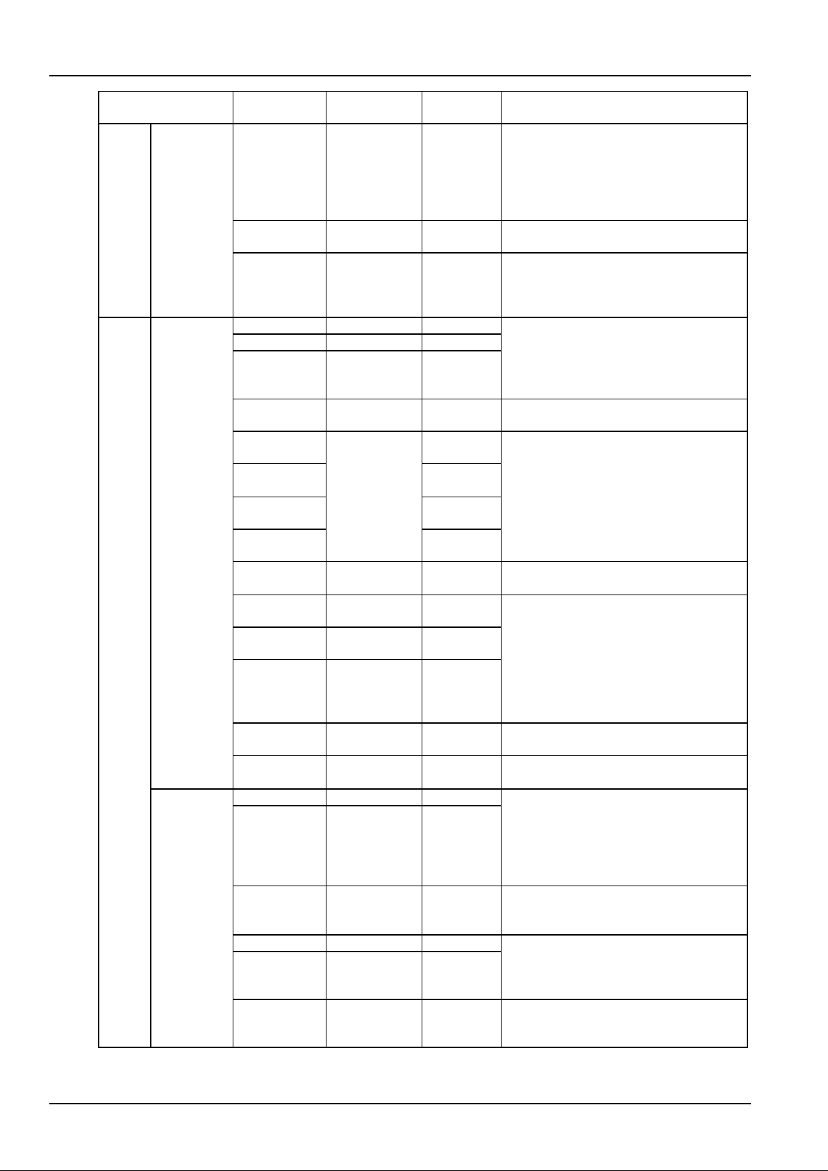
62 Appendix 3 Parameter Setting Of The Controller
NetSure 731 CC2, NetSure 731 C62 Series Power Supply System User Manual
Item
Parameter
Range
Factory
setting
Value description
Battery
Charge
management
Cyclic Boost
Period
48h ~ 8760h
2400h
Select ‘Y’, and the controller w ill c ontrol the
power system to enter the Cyclic Boost when
the FC time reaches the Cyclic Boost Interval.
The battery charging voltage is the preset
Boost, and the time is the preset Cyclic Boost
Time
Cyclic Boost
Time
30min ~
2880min
720min
Boost Limit
Time
60min ~
2880min
1080min
To ensure safety, the controller w ill forcibly
control the power system to enter the FC state
if during the BC state, the BC time reaches the
Boost Limit
Battery
Battery test
End Test Volt
43.1V ~ 57.9V
45.2V
The controller w ill stop the test and change to
FC if the battery voltage reaches the Battery
Test Voltage, or the discharge time reaches
Battery Test Time, or the battery capacity
reaches Test End Cap
End Test Time
5min ~ 1440min
300min
End Test Cap
0.01C
10
~
0.95C10
0.7C10
Cyc Test En
Y, N
Y
Select ‘Y’ to enable this function
Select ‘N’ to disable this function
Cyc Test Time
1
Month, day,
time
01-01-00:00
When the parameter Cyc Test En is set to Y,
the controller will test the battery
Cyc Test Time
2
04-01-00:00
Cyc Test Time
3
07-01-00:00
Cyc Test Time
4
10-01-00:00
Short Test
Enable
Y, N Y Whether using Short Test function
Short Test
Alarm
1A ~ 100A
10A
If the battery is not discharged w ithin the Short
Test Period, the controller will start a short
test, whose operation time is set by the
parameter Short Test Time. By the end of the
test, if the difference in the discharge current
of two batteries is bigger than the Short Test
Alarm, the battery discharge imbalance alarm
will be raised
Short Test
Period
24h ~ 8760h
720h
Short Test
Time
1min ~ 60min
5min
Stable Test
Enable
Y, N N Whether using Stable Test function
Stable Test
Current
0 ~ 9999A
9999A
Battery discharging current under stable test
Temperature
coefficient
Center Temp
10°C ~ 40°C
25°C
FC = BattTemp – Center Temp) * Temp
Coeff
Upon alarms such as Rect Not Respond, DC
Volt High, DC Volt Low and Batt Fuse Alarm,
the controller will not do temperature
compensation to the battery FC voltage
Coeff
0 ~ 500mV/°C
72mV/°C
Temp
Ambient Temp,
None, Battery
Temp
None
Measurement of ambient temperature, battery
temperature, no measurement
Batt T H2
-40°C ~ 100°C
50°C
When the detected battery temperature is
higher than the set value, the controller will
raise an alarm. The Batt T H1 must not be
higher than the Batt T H2
Batt T H1
-40°C ~ 100°C
50°C
Batt T L1
-40°C ~ 100°C
0°C
When the detected battery temperature is
lower than the set value, the controller w ill
raise an alarm
Page 69

Appendix 3 Parameter Setting Of The Controller 63
NetSure 731 CC2, NetSure 731 C62 Series Power Supply System User Manual
Item
Parameter
Range
Factory
setting
Value description
AC
Over Volt
50V ~ 300V
280V
Pow er system AC input over voltage alarm
point
Low Volt
50V ~ 300V
180V
Pow er system AC under voltage alarm point,
The value of the Low Volt must lower than that
of the Over Volt
Under Volt
50V ~ 300V
80V
Setting according to actual requirement
AC In
Auto, No,
Manual
No
Setting according to the AC input mode of AC
sampling board. Choose ‘No’ if the AC
sampling board is not configured
AC PH
1-PH, 3-PH
3-PH
Setting according to the actual configuration.
Choose 1-PH or 3-PH if the AC sampling
board is configured
DC
Over Volt
40V ~ 60V
58.5V
DC overvoltage alarm point
Low Volt 1
45.0V
DC low-voltage alarm point, must be lower
than DC overvoltage alarm point
Low Volt 2
45.0V
DC undervoltage alarm point, must be lower
than DC low-voltage alarm point
L-Shunt
Y, N N Setting according to the actual instance
Shunt Coeff
Current
1A ~ 5000A
-
They can be reset when the shunt options are
‘SET’ in the power system with load shunt
Shunt Coeff
Volt
1mV ~ 500mV
-
Rectifier
Position En
Y, N
Y
‘Y’: The controller w ill prompt you to set
rectifier position before the rectifier and
controller are pow ered on.
‘N’: You need not to set rectifier position
R-Posi
1 ~ 30
-
R-Posi: represented in two figures, the first
figure represents the rectifier number, the next
figure represents position number. Press ENT
to select the rectifier, press ◄ or ► to change
position number. When the controller
communicates with the rectifier, the green
indicator on the corresponding rectifier will
blink
HVSD
56V ~ 59V
59V
Rectifier overvoltage alarm point
Default V
48V ~ 58V
53.5V
Output voltage w hen communication
interrupted. Must be lower than the HVSD
voltage
Walk-in On
Y, N
N
The output soft start function means the
rectifier voltage w ill rise from 0V to the Default
Volt after the Walk-in time
Walk-in
8s ~ 128s
8s
Interval T
0 ~ 10s
0s
The controller can set the DCDC Interval Start
of the rectifiers.
Start time = rectifier address * interval time
AC OverV On
Y, N
N
The controller can set the rectifier to OverVolt
Enable, meanwhile, the rectifier can start
forcibly. The controller will set automatically
the rectifier with least address to have this
function. If the rectifier alw ays exceeds the
normal voltage for 60s, the function w ill be
cancelled automatically
ACCurrLim
1A ~ 50A
30A
The controller limits the input current of the
rectifier in the AC current limiting.
System
Lang
Chinese,
English
Chinese
Set according to your need
Tzone
- - Set according to actual instance
Date
2000 ~ 2099
-
Set the time according to the current actual
time, regardless of whether it is a leap year or
not
Page 70
64 Appendix 3 Parameter Setting Of The Controller
NetSure 731 CC2, NetSure 731 C62 Series Power Supply System User Manual
Item
Parameter
Range
Factory
setting
Value description
System
System Type
24V/100
24V/300
24V/500
24V/1000
24V/SET
48V/100
48V/300
48V/500
48V/1000
48V/SET
NetSure 731
C62:
48V/300
NetSure 731
CC2:
48V/500
The system type of the controller has been set
according to the actual instance before the
controller is delivered with power system. You
need not to change the value except that the
controller is replaced w ith a new one.
After changing the type, the controller will
restart and the other parameters will resume
the default. You need to reset and change
some parameters according to the battery and
equipment configured with system
ComDownLoad
Y, N
N
Whether resetting the password to the default
Reset PWD
Y, N
N
Reset Para
Y, N N Whether resetting the parameter to the default
Op1 PWD
-
-
The passw ord can be 6 digits long at most. If it
is shorter than 6 digits, end it with a #
Op2 PWD
- - Adm PWD
-
-
Communication
Address
1 ~ 254
1
The addresses of power systems that are at
the same monitored office should be different
Comm Mode
Modem
RS232
The power system only supports RS232 mode
communication
BaudRate
1200bps ~
9600bps
9600bps
Make sure the baud rates of both the sending
and receiving parties are the same
IP/Subnet/Gate
-
-
Set according to actual instance
CallbackTime
-
-
Phone Number
-
-
Energy saving
Save Enable
Y, N
N
It can be set to ‘Y’ when the battery is
configured and load current without instantly
shocks
Cyc Period*
1h ~ 8760h
48h
Time of rectifier under power-on state and
power-off state, it can be set according to
actual requirement
Rect Work
30% ~ 90%
80%
Output capacity percentage. More rectifiers will
startup to work when larger than this setting
percentage
Rect Limit
1 ~ 30
1
Minimum number of the rectifier
Fast settings
System Type
24V/100
24V/300
24V/500
24V/1000
24V/SET
48V/100
48V/300
48V/500
48V/1000
48V/SET
NetSure 731
C62:
48V/300
NetSure 731
CC2:
48V/500
The system type of the controller has been set
according to the actual instance before the
controller is delivered with power system. You
need not to change the value except that the
controller is replaced w ith a new one.
After changing the type, the controller will
restart and the other parameters will resume
the default. You need to reset and change
some parameters according to the battery and
equipment configured with system
Capacity
50Ah ~ 5000Ah
300Ah
The capacity of the total battery strings. You
should set this parameter according to the
actual battery configuration
Note*: Cyc Period, Rect Work and Rect Limit are available when ‘Save Enable’ is set to ‘Y’
Page 71
Appendix 4 Menu Structure Of The Controller 65
NetSure 731 CC2, NetSure 731 C62 Series Power Supply System User Manual
Appendix 4 Menu Structure Of The Controller
Main Menu
MaintenanceStatus Settings
Rectifiers
DC Voltage
DC Current
AC on/off
AC Voltage
Curr Limit
AC Derated
Temp Derated
DC on/off
Active
Alarm
Alarm serial No.
Alarm level
Alarm name
Alarm time
Alarm
History
Start
FC
BC
Test
Rect Trim
Rectifier
DC ON
DC OFF
AC ON
AC OFF
Rect Limit
Reset
Alarm
Settings
Alarm
Type
Alarm
Mode
Alarm
Control
Battery
Settings
OverVolt 280V
LowVolt 180V
UnderVolt 80V
AC Input
Alarm Type
Level
Relate Relay
DI No.
Mode
Set DI Name
Voice Sign
Clear Hist Alarm
AC
Settings
Over Volt
Low Volt
Under Volt 45.0V
DC
Settings
Load Shunt N
Shunt Coeff Volt
Position En
Y
HVSD
Default V
Walk-in On
Rectifier
Settings
Interval T
0s
AC OverV On
N
System
Settings
Lang
Date
Chinese
System Type
ComDownLoad
Reset PWD
Reset Para
--See Figure 4
Note:
1. 'Status' information can be queried only. Refer to
Figure 4 for system information.
2.
Operator level authority is compatible with user level
authority. Administrator level authority is compatible
with operator level authority.
3. Parameters on the right side are default values set
before delivery.
No
Alarm serial No.
Alarm name
End time
Start time
58.5V
45.0V
59V
53.5V
N
Walk-in 8s
AC PH 3-PH
Shunt Coeff Current
ACCurrLim
30A
Address 1
Comm Mode RS232
BaudRate 9600bps
CallbackTime
Phone Number
Change Password
Tzone
N
N
N
IP/Subnet/Gate
Communication
Settings
Energy Saving
Fast Settings
Save Enable N
Cyc Period 48h
Rect Work 80%
Rect Limit
1
System Type
PS48300-3B/2900: 48V/300
PS48600-3B/2900: 48V/500
Capacity
300Ah
R-Posi
PS48300-3B/2900: 48V/300
PS48600-3B/2900: 48V/500
NetSure 531 CA1
NetSure 531 CA1
PS48300-3B/2900: 48V/300
PS48600-3B/2900: 48V/500
PS48300-3B/2900: 48V/300
PS48600-3B/2900: 48V/500
Figure 6 Menu structure of the controller
Page 72
66 Appendix 4 Menu Structure Of The Controller
NetSure 731 CC2, NetSure 731 C62 Series Power Supply System User Manual
Basic
Sys Mode
Auto
2
Capacity
Bat. Shunt2 Y
Bat. Shunt1
LVD
LVD1 Enable Y
LVD2 Enable
Y
LVD1 Volt
44.0V
Charge
Float
53.5V
Boost
56.4V
limit
Over 0.3C 10
Automatic Boost Enable Y
Temp
Comp
Temp
None
Center Temp
25℃
72mv/℃
Batt T H2
LVD2 Volt 43.2V
Automatic Boost Current
Automatic Boost Cap 80%
0.01C10
Cyclic Boost Enable
Cyclic Boost Period
180min
Cyclic Boost Time 2400h
720min
Boost Limit 1080min
Bat. Test
End Test Volt 45.2V
300min
End Test Cap
Cyc Test En N
Cyc Test Time1
Short Test Time
N
Stable Test Enable
10A
720h
50℃
0℃
Battery Settings
DC voltage
DC current
System information
System
operation
state
Normal
Alarm
Power
management
mode
Battery
management
mode
Battery
state
Auto
Manual
FC
BC
Temperature compensation
Cyclic Boost
Test
Short Test
Cyc Test
Battery1 current
Battery1 remaining capacity
AC voltage
System Power
Cyc BC After
Bat. Temp
Amb. Temp
Battery2 current
Battery2 remaining capacity
Bat. Fuse
Shunt Coeff Current
Const Boost Current
Boost Limit Time
End Test Time
0.7C 10
00:00, Jan.1
st
Short Test Enable
Short Test Alarm
Short Test Period
00:00, April1
st
00:00, July1
st
00:00, Oct.1
st
Stable Test Current
Batt T H1
Batt T L1
50℃
0.1C 10
Note:
1.
System information is queried in system
information page.
2.
Press ESC at system information page, you can
query the serial number and software version of
the monitoring module.
4.
Parameters on the right side are default values
set before delivery.
Basic parameters should be reset according to
actual configuration.
3.
Shunt Coeff Volt 25mV
Y
0.06C
10
Y
Cyc Test Time2
Cyc Test Time3
Cyc Test Time4
5min
N
9999A
Coeff
Energy Saving
300Ah
500A
Figure 7 Menu structure of battery settings
Page 73
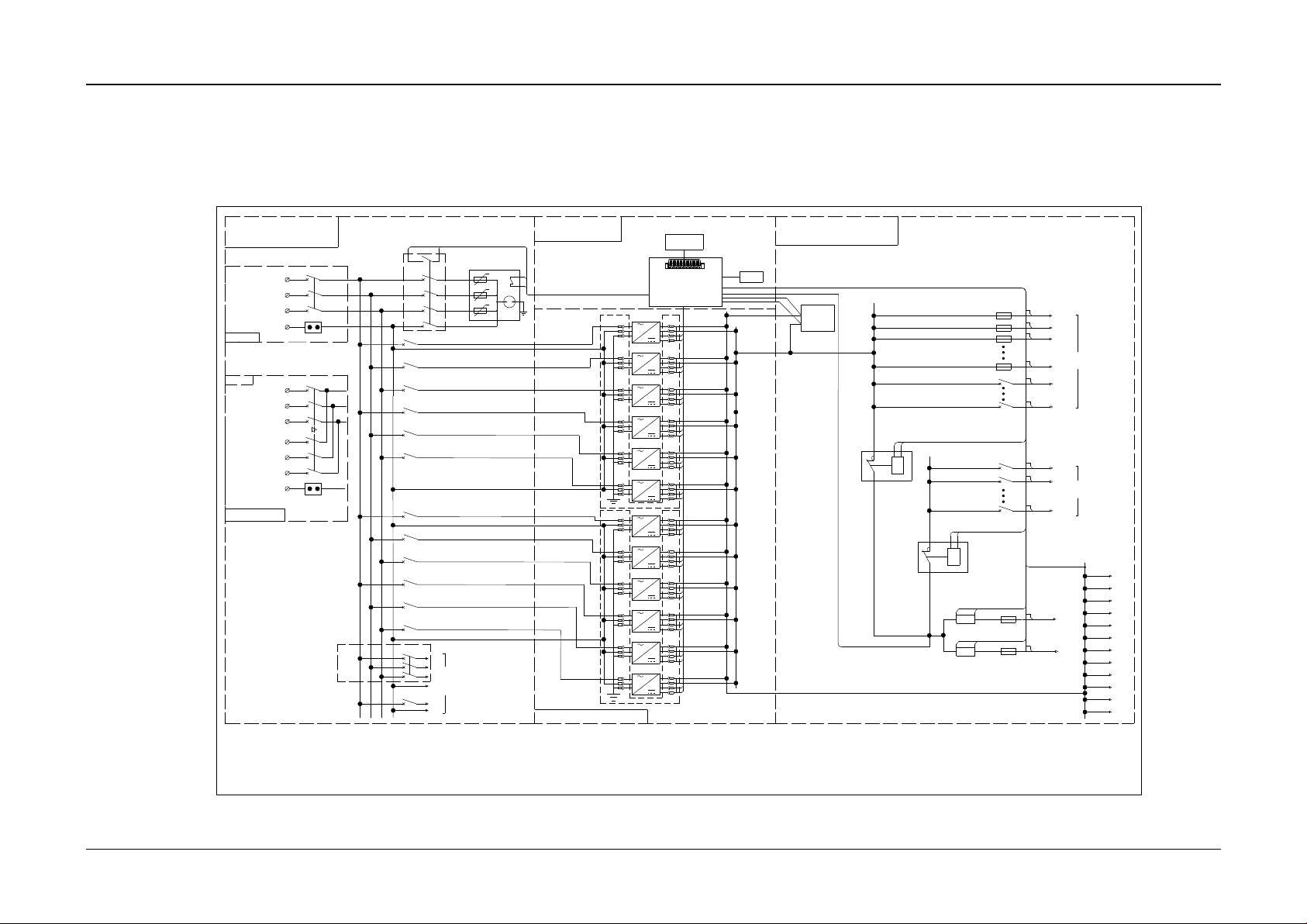
Appendix 5 Schematic Diagram 67
NetSure 731 CC2, NetSure 731 C62 Series Power Supply System User Manual
Appendix 5 Schematic Diagram
FUB2
FUB1
KMD2
SPD1
LLVD
BLVD
Battery 1
Battery 2
QFA3
QFA4
AC Output
AC distribution unit
DC distribution unit
M2433X2
KMD1
Monitor unit
Rectifier unit
RB2
RB1
PE
PA1
M522S
Monitor Module
0V
QFA5
W1
V1
U1
mains inputⅠ
QFA1
N1、2
mains inputⅡ
U2
V2
W2
QFA2
QFA1
mains input
U
V
W
N
QFA6
QFA7
QFA8
QFA9
QFA10
QFA11
QFA12
QFA13
QFA14
QFA15
QFA16
FUD1
FUD2
FUD3
NPL
FUDn
QFD1
QFDn
PL
QFDn+1
QFDn+2
QFDn+m
-48V
0V
SPD2
0V
-48V
Optional
2
31
32
1
LCD
AC single input
temp
Optional
L1
L2
L3
N
L1
L2
L3
N
L1 L2 L3 N
CAN+
CAN-
H1
CAN+
CAN-
H2
CAN+
CAN-
H3
CAN+
CAN-
H4
CAN+
CAN-
H5
CAN+
CAN-
H6
CAN+
CAN-
H7
CAN+
CAN-
H8
CAN+
CAN-
H9
CAN+
CAN-
H10
CAN+
CAN-
H11
CAN+
CAN-
H12
Module PCB1
Module PCB2
1QF1
2.NetSure 731 CC2-X3 and NetSure 731 CC2-X4 with SPD switch 1QF1,no QFA3 switch.
Double AC manual in put
Optional three-phase output
Lightning s witch option al
Note:1.NetSure 731 CC2-X1 and NetSure 731 CC2-X2 with SPD switch 1QF1,no QFA3 switch.
LLVD contactor
BLVD contactor
Figure 8 NetSure 731 CC2 schematic diagram
Page 74
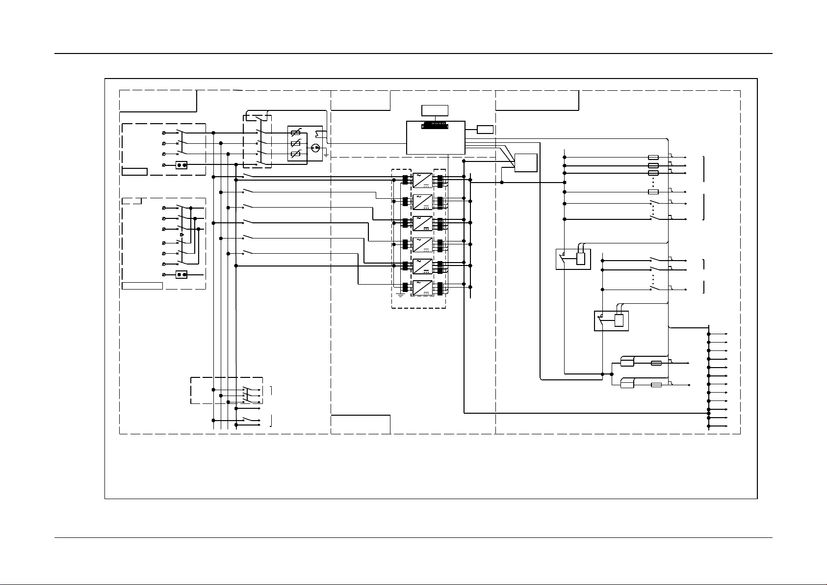
Appendix 5 Schematic Diagram 68
NetSure 731 CC2, NetSure 731 C62 Series Power Supply System User Manual
Figure 9 NetSure 731 C62 schematic diagram
FUB2
FUB1
KMD2
SPD1
LLVD
BLVD
Battery 1
Battery 2
QFA3
QFA4
AC Output
AC distribution unit
DC distribution unit
KMD1
Monitor unit
Rectifier unit
RB2
RB1
PE
PA1
M522S
Monitor Module
0V
QFA5
W1
V1
U1
Mains input?
QFA1
N1?2
Mains input?
U2
V2
W2
QFA2
QFA1
Mains input
U V W N QFA6
QFA7
QFA8
QFA9
QFA10
FUD1
FUD2
FUD3
NPL
FUDn
QFD1
QFDn
PL
QFDn+1
QFDn+2
QFDn+m
-48V
0V
Double AC manual input
AC s ingle input
2
31
32
1
LCD
Temp
Module PCB1
CAN+
CAN-
H1
CAN+
CAN-
CAN+
CAN-
CAN+
CAN-
CAN+
CAN-
CAN+
CAN-
H2
H3
H4
H5
H6
L1
L2
L3
N
Optional
L1
L2
L3 N L1
L2
L3
N
M2433X2
SPD2
CAN+
CAN+
0V
1QF1
Lightning switch (optional)
Note: 1. NetSure 731 C62-X1, Ne
tSure 731 C62-X2 are configured
with SPD switch1QF1, no QFA3.
2. NetSure 731 C62-X1 is differe
nt from the cabinet structure of
NetSure 731 C62-X2.
4. NetSure 731 C62-X3 cabinet ha
s no battery rack and SPD switch
1QF1, is configured with QF3 MC
B.
3. NetSure 731 C62-X1 cabinet is
with no battery rack, the NetSu
re 731 C62-X2 cabinet is equippe
d with two battery racks.
Three-phase output
Page 75
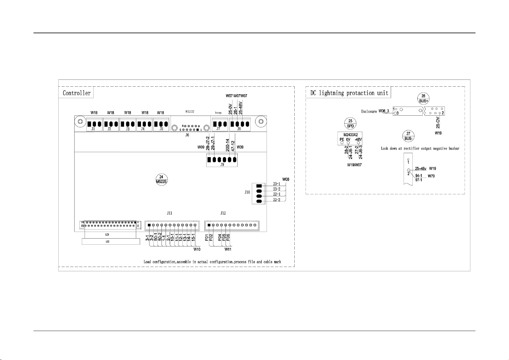
Appendix 6 Wiring Diagram 69
NetSure 731 CC2, NetSure 731 C62 Series Power Supply System User Manual
Appendix 6 Wiring Diagram
Figure 10 Wiring diagram of NetSure 731 C62-X1 (1)
Page 76
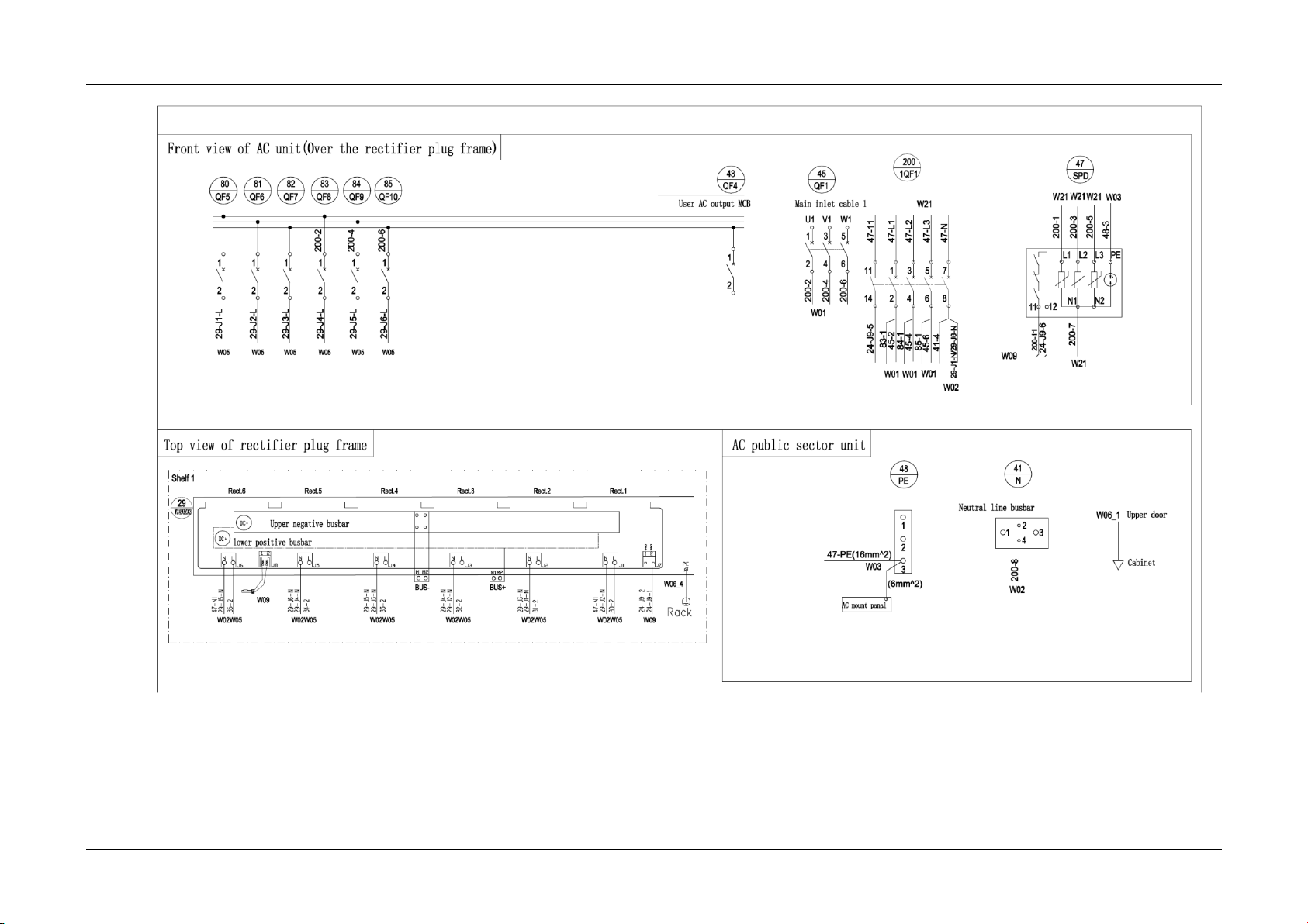
Appendix 6 Wiring Diagram 70
NetSure 731 CC2, NetSure 731 C62 Series Power Supply System User Manual
Figure 11 Wiring diagram of NetSure 731 C62-X1 (2)
Page 77
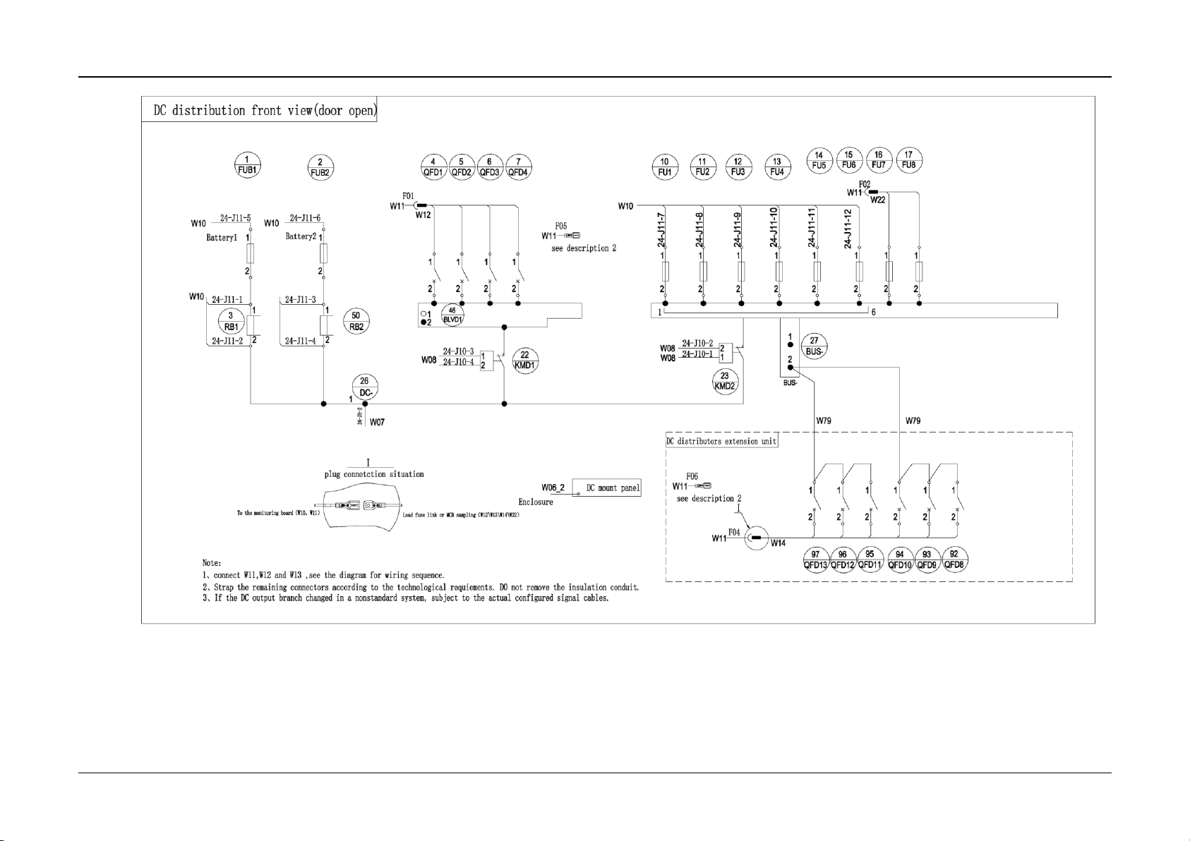
Appendix 6 Wiring Diagram 71
NetSure 731 CC2, NetSure 731 C62 Series Power Supply System User Manual
Figure 12 Wiring diagram of NetSure 731 C62-X1 (3)
Page 78
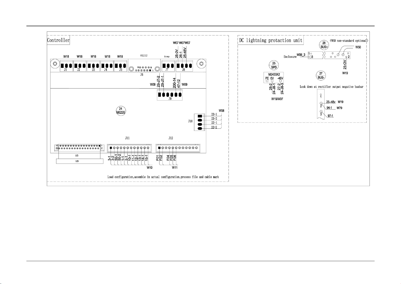
Appendix 6 Wiring Diagram 72
NetSure 731 CC2, NetSure 731 C62 Series Power Supply System User Manual
Figure 13 Wiring diagram of NetSure 731 C62-X2 (1)
Page 79
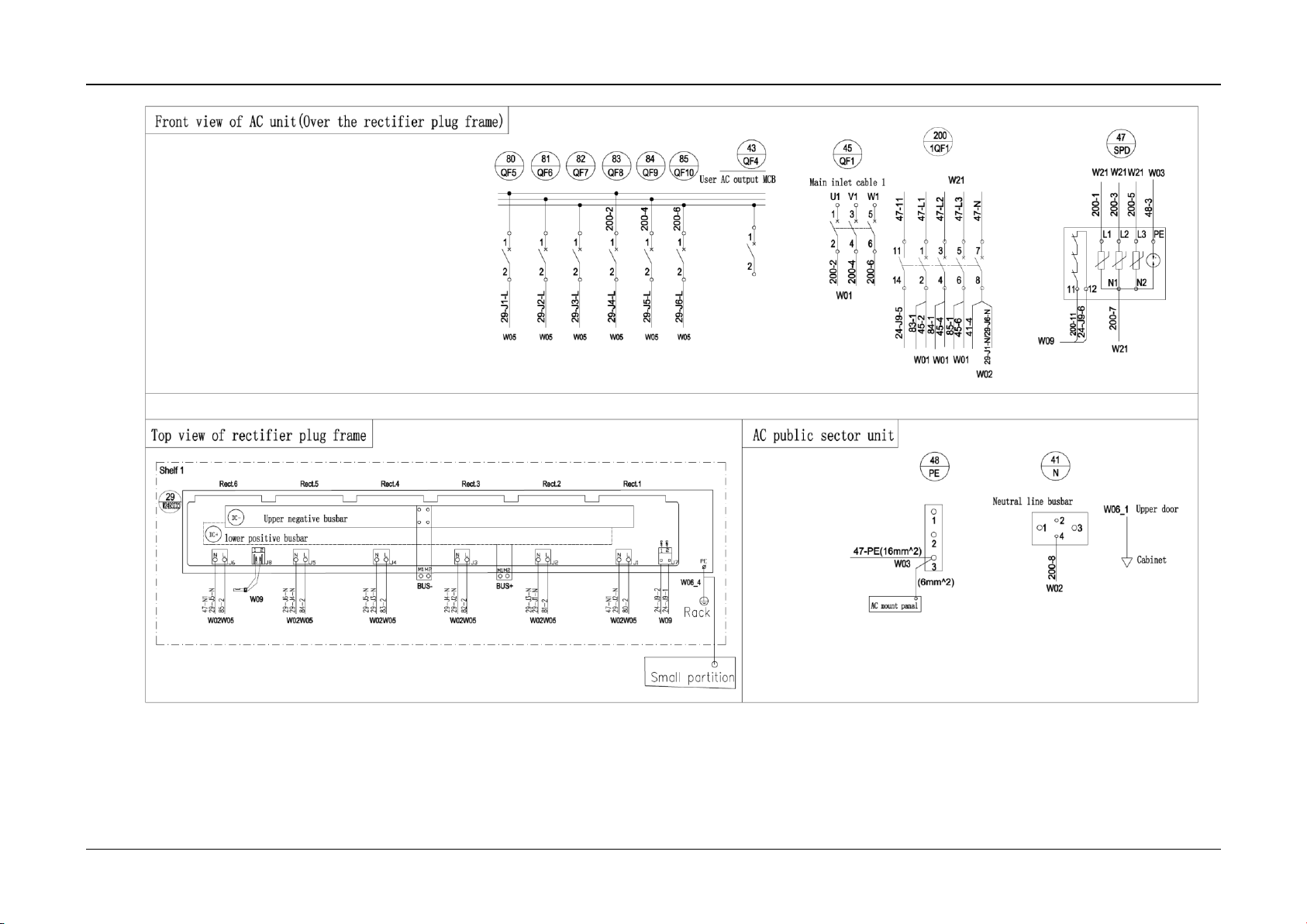
Appendix 6 Wiring Diagram 73
NetSure 731 CC2, NetSure 731 C62 Series Power Supply System User Manual
Figure 14 Wiring diagram of NetSure 731 C62-X2 (2)
Page 80
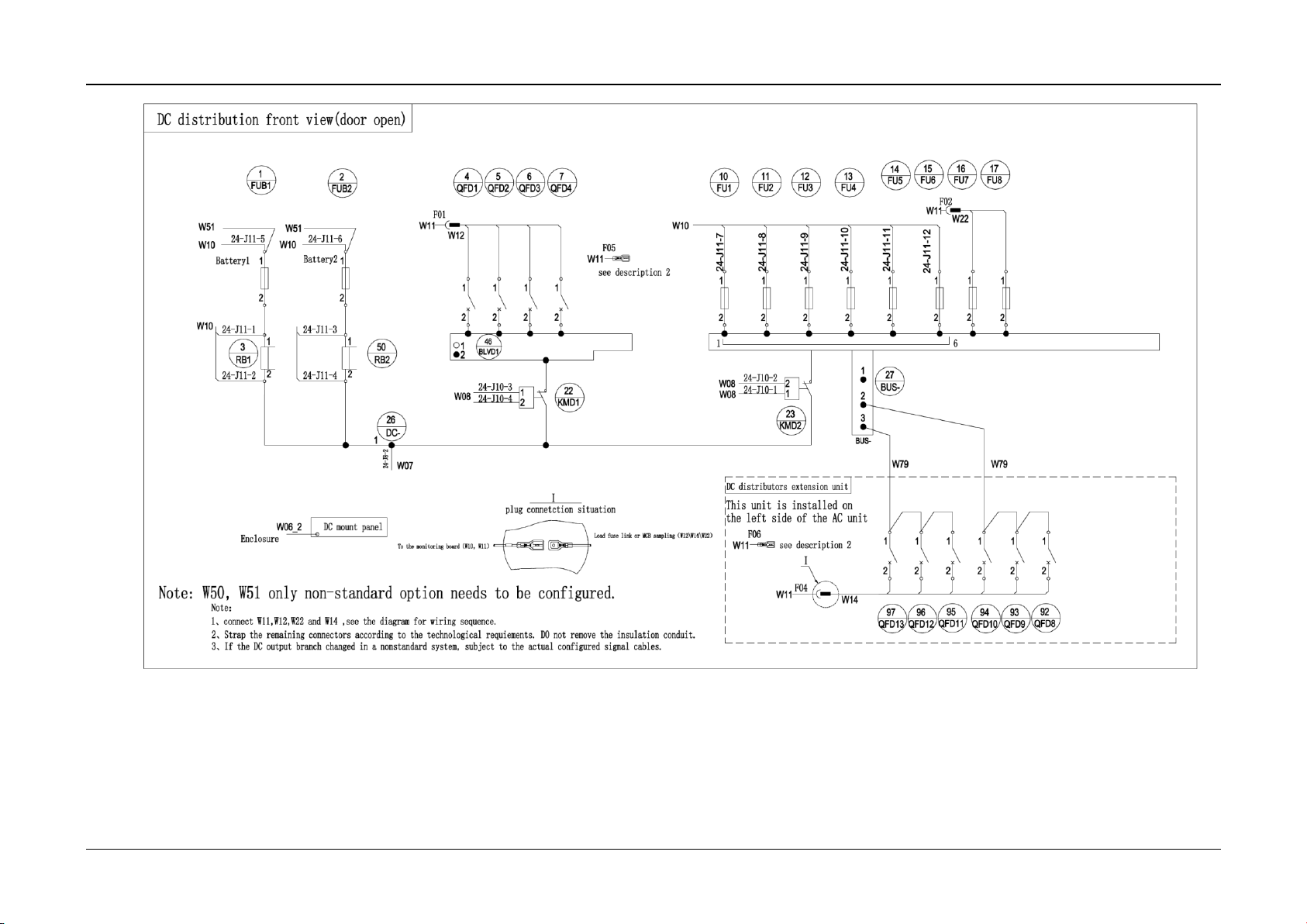
Appendix 6 Wiring Diagram 74
NetSure 731 CC2, NetSure 731 C62 Series Power Supply System User Manual
Figure 15 Wiring diagram of NetSure 731 C62-X2 (3)
Page 81
Appendix 6 Wiring Diagram 75
NetSure 731 CC2, NetSure 731 C62 Series Power Supply System User Manual
2
31
32
1
15
9
6
24
M522S
W08
W09
W09
W10 W11
W07W07W07
BUS+
27
BUS-
28
1
2
W19
W06_3
3
SPD
25
M2433X2
-48VPE 0V
W19/W07
J1 J2 J3 J4 J5
J6
J7
J8
J9
J10
J12
J11
Temp
29-J7-2
23-1
23-2
22-1
22-2
3-1
3-2
1-1
2-1
10-1
11-1
12-1
13-1
LCD
RS232
25-0V
26-1
25-48V
47-12
47-11
Controller
液晶
50-1
50-2
25-OV
Look down at rectifier output ne gative busbar
Enclosure
28-2
27-2
24-J8-1
24-J8-3
Load configuration, assemble in actual configuration, process fi le and cable mark
DC lightning protection unit
W18 W18 W18 W18 W18
29-J7-1
F02
F01
F04
F05
F06
1
2
25--48v W19
94-1
W79
Note:
1. For WJ465ZCX3 standard config uration connection, see wiring d iagram 1, 2 and 3.
2. For non-standard configuratio n that changed the AC input, see wiring diagram 4 for AC input c onnection.
15-1
Figure 16 Wiring diagram of NetSure 731 C62-X3 (1)
Page 82
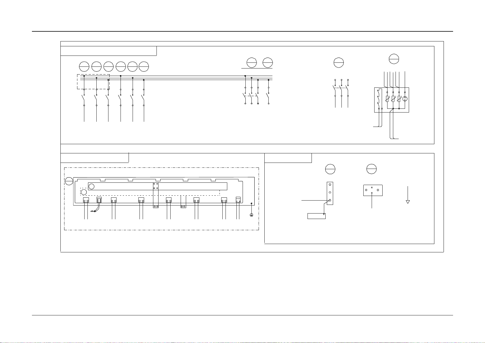
Appendix 6 Wiring Diagram 76
NetSure 731 CC2, NetSure 731 C62 Series Power Supply System User Manual
1
N1
12
PEL2L1 L3
11
Mains inlet cable 1
U1 V1 W1
642
1 3 5
1234561
2
43
QF4
42
QF3
45
QF1
47
SPD
48
PE
W01
W01
AC mount panel
2
3
W02
W03
W06_1
W09
1
2
1
2
1
2
QF5
80 81 82
QF6 QF7
1
2
1
2
1
2
QF8 QF9 QF10
4
2
3
Neutral line busbar
41
N
W02
1
83 84 85
W05 W05 W05 W05 W05 W05
W01 W01 W01
AC public sector unit
Upper door
Cabinet
47-L1
47-L2
47-L3
45-2
48-3
47-PE(16mm^2)
45-4
45-6
83-1
84-1
85-1
41-4
24-J9-5
24-J9-6
29-J1-N/29-J6-N
User AC output MCB
29-J1-L
(6mm^2)
47-N1
Top view of rectifier plug frame
29
W2493ZX2
J6
J5
J4 J3
J2
J1
LN
J7
J8
M1
M1
W05
80 -2
W02
29 -J1-N
29 -J3-N
M2
M2
DC-
DC+
Upper negative busbar
Lower positive busbar
29 -J5-N
Rack
PE
W05W02W05W02W05W02W05W02W05W02
LNLNLNLNLN
29 -J2-N
47 -N1
BUS- BUS+
Rect.1Rect.2Rect.3Rect.4Rect.5Rect.6
Shelf 1
29-J2-L
29-J3-L
29-J4-L
29-J5-L
29-J6-L
81 -2
82 -2
83 -2
84 -2
85 -2
29 -J2-N
47 -N1
29 -J4-N
47-L2
47-L1
47-L3
W06_4
N2
CAN+
CAN-
21
W09
W09
24 -J9-2
24 -J9-1
Front view of AC unit (over the rectifier plug frame)
CAN+
CAN-
1 2
29 -J6-N
29 -J5-N
29 -J4-N
29 -J3-N
For non-standard configuration
47-L1
47-L2
47-L3
Figure 17 Wiring diagram of NetSure 731 C62-X3 (2)
Page 83
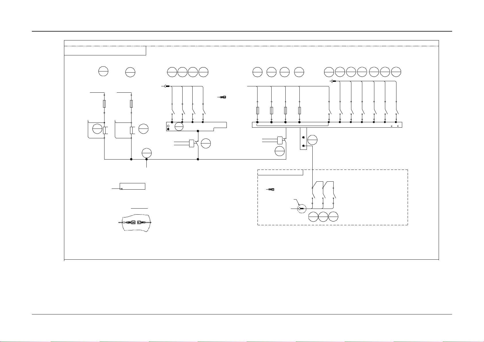
Appendix 6 Wiring Diagram 77
NetSure 731 CC2, NetSure 731 C62 Series Power Supply System User Manual
FU2
FU1
10 11
22
KMD1
2
FUB2
Battery 2
1
RB1
3
FUB1
Battery 1
1
2
1
2
1
2
2
1
1
2
1
2
4
QFD1 QFD4
7
23
KMD2
2
1
26
DC-
1
W07
24-J10-3
24-J10-4
24-J10-2
24-J10-1
W08
W08
W08
24-J11-1
24-J11-2
W10
24-J11-5 24-J11-6
W10
W10
W10
1
2
24-J11-3
24-J11-4
RB2
50
1
2
17
1
2
FU312FU4
13
To monitoring board(W10,W11
)
BLVD1
46
1
2
16
9294 93
24 -J8-2
24-J11-7
24-J11-8
24-J11-9
24-J11-10
Note:
1. Connect W11, W12 and W13, see the diagram for w iring sequence .
2. Strap the remaining connector s according to the technological requirements. Do not remove the insulation conduit.
Ⅰ
Plug connection situation
DC distribution extension unit
1 6
直流安装板
W06_2
机壳
2
1
5
QFD26QFD3
21212
1
15
212
1
18
2
1
19
2
1
20
2
1
1
2
1
2
1
2
BUS-
F01
W11
W11
F02
W11
F04
W12
Ⅰ
Load fuse link or MCB sampling(W 12\W13\W14
)
QFD1
21
2
1
2
1
QFD2 QFD3 QFD4 QFD5 QFD6 QFD7
2
W11
F05
see Note 2
1
27
BUS-
W11
see Note 2
F06
QFD8QFD9
QFD10
W14
W13
DC distribution front view (door open)
W79
24-J11-12
3. If the DC output branch chang ed in a non-standard system, sub ject to the actual configured si gnal cables.
Figure 18 Wiring diagram of NetSure 731 C62-X3 (3)
Page 84
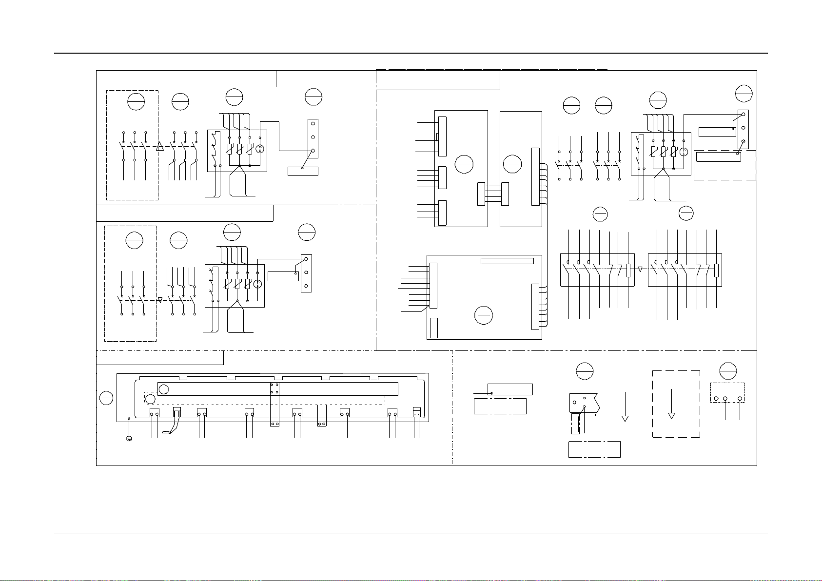
Appendix 6 Wiring Diagram 78
NetSure 731 CC2, NetSure 731 C62 Series Power Supply System User Manual
DC installation guide rail
W06_5
Enclosure
12
PEL2L1 L3
11
47
SPD
W09
Mains inlet cable 2
U1 V1 W1U2 V2 W2
12345
6 642
1 3 5
44
QF2
45
QF1
W01W01
W01
W03
12
PEL2L1 L3
11
47
SPD
W09
U1 V1 W1U2 V2 W2
12345
6 642
1 3 5
44
QF2
45
QF1
W01
W01
W01 W01
W01 W01W01
for dual-mains auto-switch input
W33W31
W33W31
W30
W30
W33W31
W33
W31
W30
W30
A2
A1
53
54
21
22
61
62642
531
44-3/53-J1-3
45-3/53-J1-7
55-6
55-4
51-XS1-1
54-6
W1
55-3
45-5
55-1
44-1/53-J1-4
44-5/53-J1-2
53
54
10
A14C3C2
b2
c2
GND
9
6
7
8
52
PA2
GND
a1
b1
c1
4
2
1
3
1
4
3
2
2J1
2XS1
a2
5
J3
GNDB1 C1 B2A2 C2
1 3 4 52 876
c2
b2
GND
a2
4
6
5
7
a1
1
b1
2
c1
3
GND 8
W35
W34
J4
A14C3S1
A1
KMA2
54
W1
55
KMA1
61
62
21 A1
A11
XS1
53-J1-8
22 A2
54-1,47-L1
54-3/47-L2
1 3 5
45-1/53-J1-8
2 4 6
54-5/47-L3
45-5/53-J1-6
PA1
51
N2N14
5
3
53-J1-5
53-J1-4
2
1
XS2
W33
54-21
55-A1
A26
coil1
A14C3C1
3
2
1
4
XS4
3
4
1
XS3
54-A1
55-61
3
4
2
W31
55-62
54-62
54-61
coil2
55-21
4
3
2
1 N2
C2
B2
A2
J1
54-4
54-2/51-XS1-6
41-3
8
7
6 C1
B1
A1
2
J2
1 N
3
W
53
PA3
55-2
52-XS1-4
5 N1
2
Mains 2 inlet Mains 1 inlet
U1 V1 W1U2 V2 W2
12345
6 642
1 3 5
44
QF2
45
QF1
W30 W30 W30 W30 W30 W30
12
PEL2L1 L3
11
47
SPD
W09
W01
51-XS2-1
55-A2
54-22
51-XS2-2
51-XS3-2
51-XS3-4
51-XS3-1
51-XS3-3
54-A2
51-XS2-3
51-XS2-4
55-22
W33
W33
W33
W33
1
48
PE
2
3
W03
1
48
PE
2
W03
3
W06_1
41
N
W02W30
W06_7
SPD
25
-48VPE 0V
W25/W07
AC input 3 at the lower plug fra me
N1 N2
W02
N1 N2
N1 N2
W02
W02
AC mount panel
AC mount panel
1
48
PE
2
W06-6
W03
AC auto-switch board
3
AC mount panel
Rear top view of rectifier plug frame
29
W2493ZX2
J6 J5 J4 J3 J2 J1
LN
J7J8
CAN+
CAN-
M1
M1
W09
24 -J9-2
W05
80 -2
W02
29 -J1-N
29 -J3-N
M2
M2
DC-
DC+
Upper negative busbar
Lower positive busbar
29 -J5-N
PE
W05W02W05W02W05W02W05W02W05W02
LNLNLNLNLN
29 -J2-N
47 -N1
W06_4 BUS- BUS+
Rect.1Rect.2Rect.3Rect.4Rect.5Rect.6
Shelf 1
81 -2
82 -2
83 -2
84 -2
85 -2
29 -J2-N
29 -J4-N
24 -J9-1
21
41-3
29-J6-N
29-J1-N
41-3
41-3
29-J6-N
29-J1-N
29-J1-N
29-J6-N
47 -N1
Rack
2
1
3
Netural line bar
CAN+
CAN-
1 2
29 -J3-N
29 -J4-N
29 -J5-N
29 -J6-N
M2433X2
45-2
45-4
45-6
80-1
81-1
82-1
24-J9-5
24-J9-6
44-2
47-L1
47-L2
44-4
47-L3
44-6
45-2
45-4
45-6
45-2
45-4
45-6
80-1
81-1
82-1
24-J9-5
24-J9-6
44-1
47-L1
47-L2
44-3
47-L3
44-5
45-1
45-3
45-5
AC input 2 optional
55-2
55-4
55-6
54-2
54-4
54-6
55-1
55-3
55-5
80-1
81-1
82-1
24-J9-5
24-J9-6
(16mm^)2
(6mm^)2
Upper door
Cabinet
53-J1-1
W30 is only for auto-switch conf iguration
Lower door
Cabinet
for optional installation
(16mm^)2
(6mm^)2
Note:
Selected when AC auto-
47-N1
24-J8-3
24-J8-1
27-2
28-2
AC input 1 and AC input 2 at the upper plug frame
Note: when AC input is under the plug frame,
(16mm^)2
(6mm^)2
Mains inlet cable 1
AC input 1 and AC input 2 at the lower plug frame
Mains inlet cable 2 Mains inlet cable 1
AC input 2 optional
switch is configured
connect this cable.
Figure 19 Wiring diagram of NetSure 731 C62-X3 (4)
Page 85
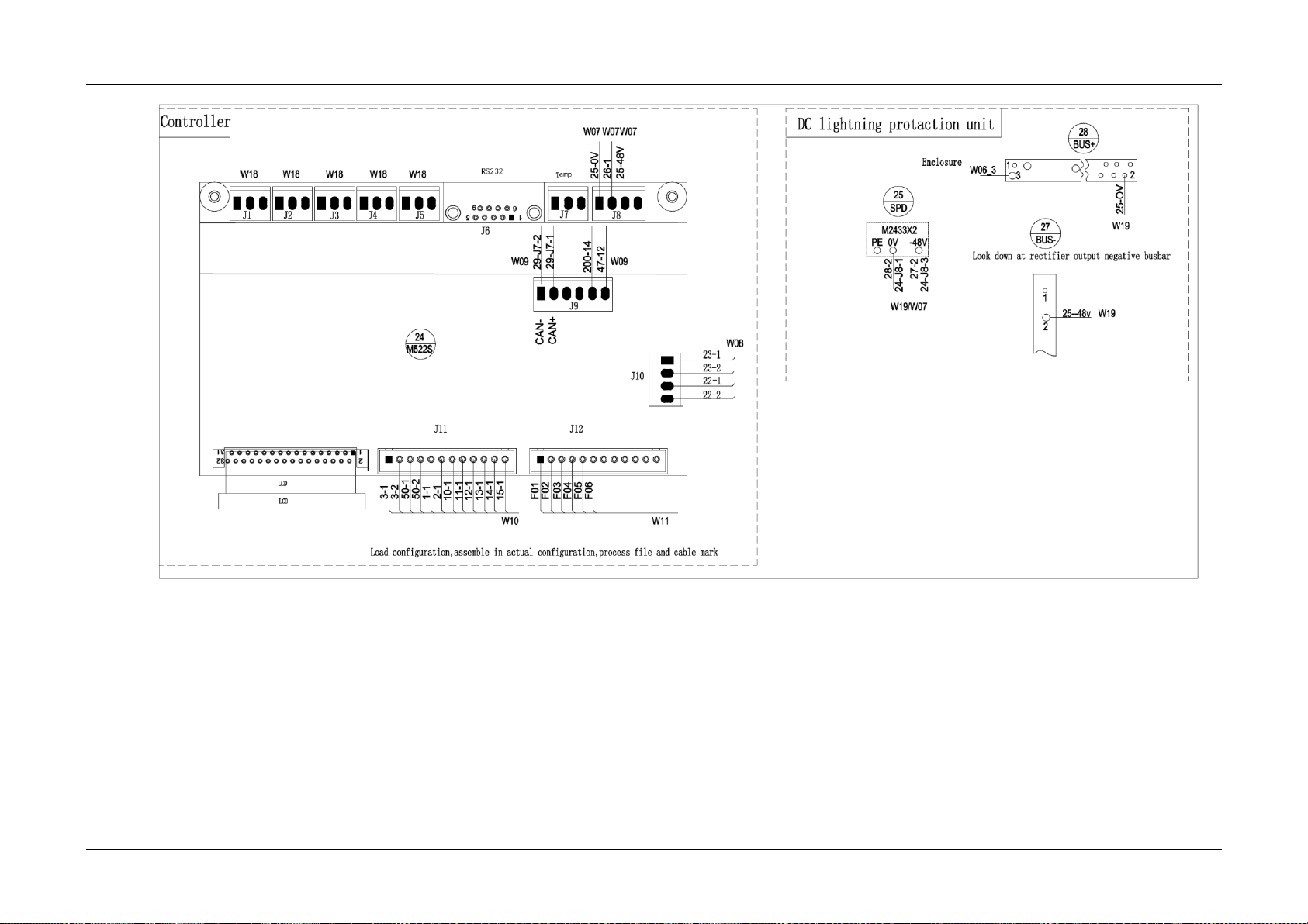
Appendix 6 Wiring Diagram 79
NetSure 731 CC2, NetSure 731 C62 Series Power Supply System User Manual
Figure 20 Wiring diagram of NetSure 731 CC2-X1 X2 (1)
Page 86
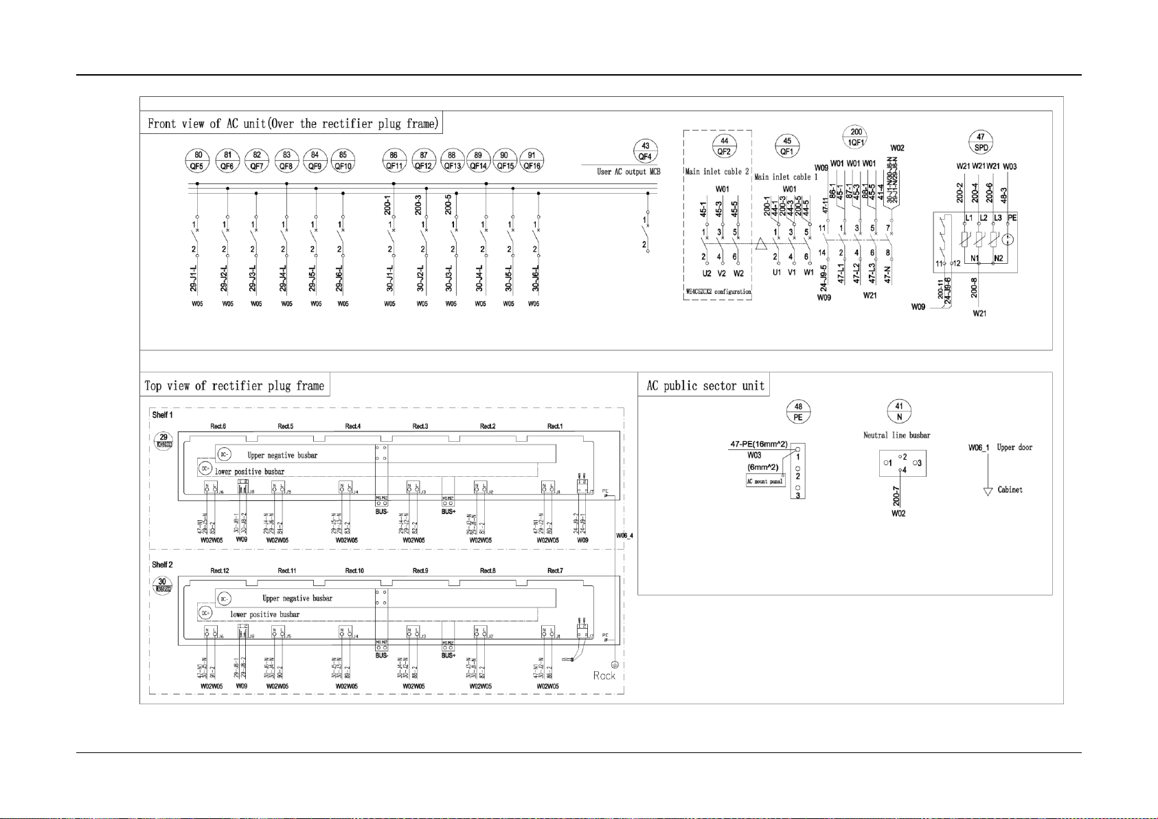
Appendix 6 Wiring Diagram 80
NetSure 731 CC2, NetSure 731 C62 Series Power Supply System User Manual
Figure 21 Wiring diagram of NetSure 731 CC2-X1 X2 (2)
Page 87
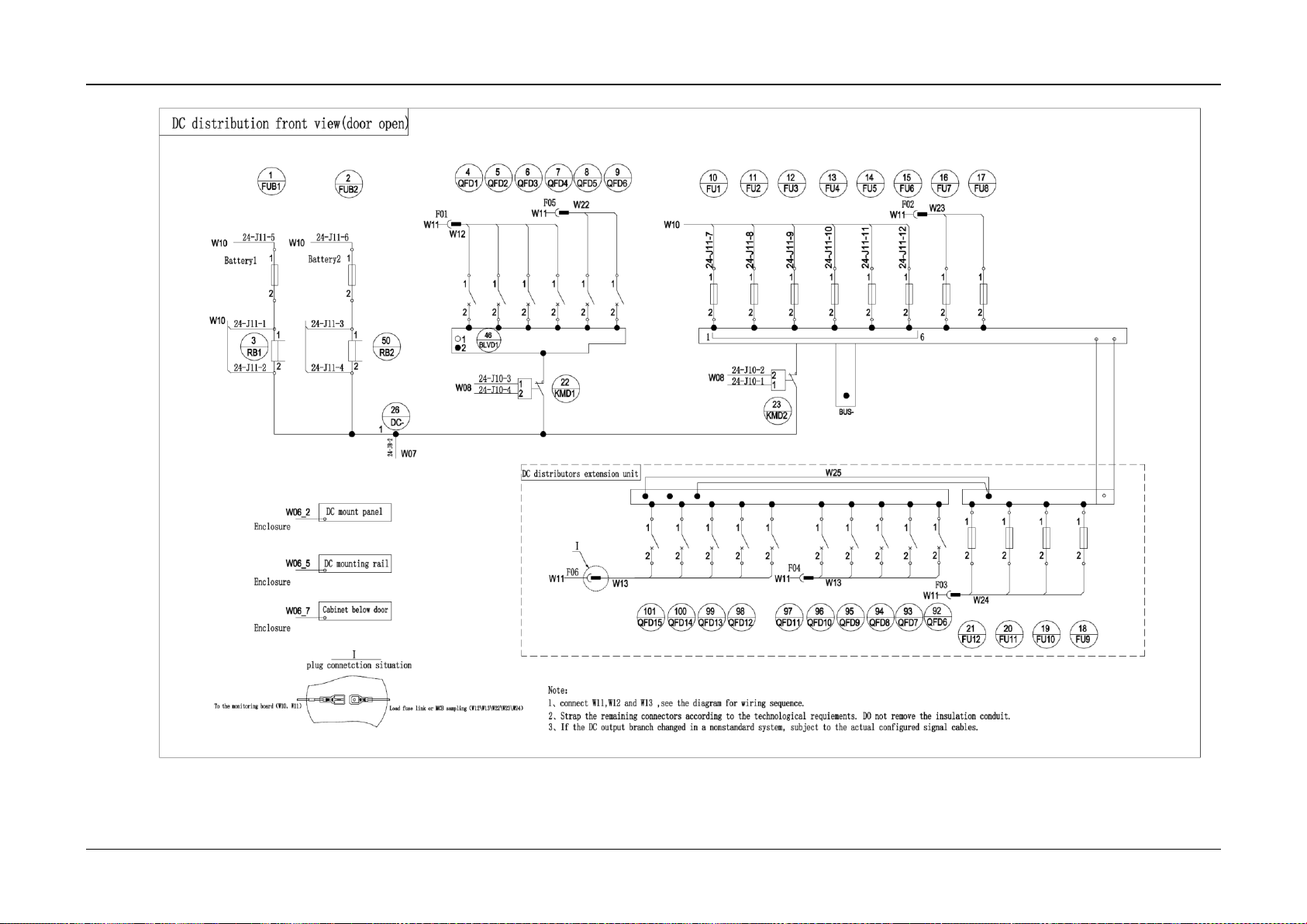
Appendix 6 Wiring Diagram 81
NetSure 731 CC2, NetSure 731 C62 Series Power Supply System User Manual
Figure 22 Wiring diagram of NetSure 731 CC2-X1 X2 (3)
Page 88
Appendix 6 Wiring Diagram 82
NetSure 731 CC2, NetSure 731 C62 Series Power Supply System User Manual
2
31
32
1
15
9
6
24
M522S
W08
W09 W09
W10 W11
W07
W07W07
1
BUS+
27
BUS-
28
2
1
2
25--48v
W19
W19
W06_3
3
SPD
25
M2433X2
-48VPE 0V
W19/W07
J1 J2 J3 J4 J5
J6
J7 J8
J9
J10
J12J11
Temp
29-J7-2
23-1
23-2
22-1
22-2
3-1
3-2
1-1
2-1
10-1
11-1
12-1
13-1
LCD
RS232
25-0V
26-1
25-48V
47-12
47-11
Controller
液晶
50-1
50-2
25-OV
Enclosure
28-2
27-2
24-J8-1
24-J8-3
W18 W18 W18 W18 W18
29-J7-1
F02
F01
F04
F05
F06
94-1
W79
15-1
DC lightning
protection unit
Load configuration, assemble in actual configuration, process fi le and cable mark
Look down at rectifier output ne gative busbar
Load configuration, assemble in actual configuration, process file and cable mark
Look down at rectifier output negative busbar
Figure 23 Wiring diagram of NetSure 731 CC2-X3 (1)
Page 89
Appendix 6 Wiring Diagram 83
NetSure 731 CC2, NetSure 731 C62 Series Power Supply System User Manual
1
U1 V1 W1
642
1 3 5
1234561
2
43
QF4
42
QF3
45
QF1
47
SPD
48
PE
W01
2
3
W03
W06_1
2
11
2
1
2
1
2
1
2
1
2
QF5
86 87 88
80 81 82
QF6 QF7
QF11 QF12 QF13
2112
1
2
121
2
1
2
89
QF890QF991QF10
4
2
3
41
N
W02
1
QF1483QF1584QF16
85
W05 W05 W05 W05 W05 W05 W05 W05 W05 W05 W05 W05
44 -2
47 -L1
47 -L2
44 -4
47 -L3
44 -6
47-PE(16mm^2)
47 -L1
47 -L2
47 -L3
29 -J1-L
(6mm^2)
47 -N1
29
W2493ZX 2
J6 J5 J4 J3 J2 J1LNJ7J8
M1
M1
W05
80 - 2
W02
29 - J1 - N
29 - J3 - N
M2
M2
DC-
DC+
29 - J5 - N
W05W02W05W 02W05W02
W05W02
W05W02
LNLNLNLNLN
29 - J2 - N
J6 J5 J4 J3 J2 J1LNJ7J8
M1
M1
W05
86 - 2
87 - 2
88 - 2
89 - 2
90 - 2
W02
M2
M2
DC-
DC+
91 - 2
W05W02W05W02W05W 02W05W02
W05W02
LNLNLNLNLN
30
W2493ZX 2
30 - J1 - N
30 - J3 - N
30 - J4 - N
30 - J5 - N
47 - N1
30 - J2 - N
30 - J2 - N
BUS- BUS+
BUS- BUS+
Rect.7Rect.8Rect.9Rect.10Rect.11Rect.12
Rect.1Rect.2Rec t.3Rect.4Rect.5Rect.6
Shelf 1
Shelf 2
29 -J2-L
29 -J3-L
29 -J4-L
29 -J5-L
29 -J6-L
30 -J1-L
30 -J2-L
30 -J3-L
30 -J4-L
30 -J5-L
30 -J6-L
81 - 2
82 - 2
83 - 2
84 - 2
85 - 2
29 - J2 - N
47 - N1
29 - J4 - N
12
PEL2L1 L3
11
W01
W09
W01W01 W01
45-2
48-3
45-4
45-6
86-1
87-1
88-1
24 -J9-5
24 -J9-6
N1 N2
W02
41 -4
29 -J1-N/29 -J6-N
30 -J1-N/30 -J6-N
CAN+
CAN-
21
CAN+
CAN-
21
W09
24 - J9 - 2
24 - J9 - 1
W09
30 - J8 - 2
30 - J8 - 1
29 - J8 - 1
29 - J8 - 2
W09
CAN+
CAN-
1 2
CAN+
CAN-
1 2
29 - J6 - N
29 - J5 - N
29 - J4 - N
29 - J3 - N
47 - N1
30 - J6 - N
47 - N1
30 - J5 - N
30 - J4 - N
30 - J3 - N
PE
W06_4
PE
47 -L1
47 -L2
47 -L3
Front view of AC unit(Over the r ectifier
plug f rame)
For nonstandard system wiring
Top view of rectifier plug frame
Lower positive busbar
Upper negative busbar
Upper negative busbar
Upper negative busbar
Rack
AC public sector unit
AC m ount panel
Neutral line busbar
Upper door
Cabinet
User AC output MCB
Mains inlet cable 1
Figure 24 Wiring diagram of NetSure 731 CC2-X3 (2)
Page 90
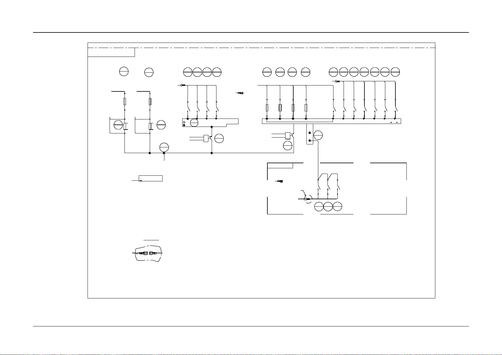
Appendix 6 Wiring Diagram 84
NetSure 731 CC2, NetSure 731 C62 Series Power Supply System User Manual
FU2FU1
10 11
22
KMD1
2
FUB2
1
RB1
3
FUB1
1
2
1
2
1
2
2
1
121
2
4
QFD1 QFD4
7
23
KMD2
2
1
26
DC-
1
W07
24-J10-3
24-J10-4
24-J10-2
24-J10-1
W08
W08
W08
24-J11-1
24-J11-2
W10
24-J11-5 24-J11-6
W10
W10
W10
1
2
24-J11-3
24-J11-4
RB2
50
1
2
17
1
2
FU312FU4
13
BLVD1
46
1
2
16
QFD2
92
QFD8
94 93
24-J8-2
24-J11-7
24-J11-8
24-J11-9
24-J11-10
Ⅰ
1 6
W06_2
2
1
5
QFD26QFD3
21212
1
QFD1
15
2
1
QFD3
2
1
18
QFD4
2
1
19
QFD5
2
1
20
QFD6
2
1
QFD9
QFD10
12121
2
BUS-
F01
W11
W11
F02
W11
F04
W12
W13
Ⅰ
W14
21
QFD7
212
1
2
W11
F05
1
27
BUS-
W11
F06
W79
24-J11-12
DC distribution f ront v iew
(door open)
Battery 1 Battery 2
DC mount panel
Enclosure
Plug connection situation
Remove the monitoring board(W 10, W1 1) Load fuse link or MCB sampling(W 12\W13\W14)
1. Connect W11 to W12 and W13, s ee the diagram for wiring sequen ce.
2. Strap the remaining connector s according to the technological requirements. Do not remove the insulation conduit.
Notes:
See description 2
See description 2
DC distributors
extention unit
Remove the monitoring board(W10,W11)
Remove the monitoring board(W10,W11)
1. Connect W11 to W12 and W13, see the diagram for wiring sequence.
2. Strap the remaining connectors according to the technological requirements. Do not remove the insulation conduit.
Figure 25 Wiring diagram of NetSure 731 CC2-X3 (3)
Page 91
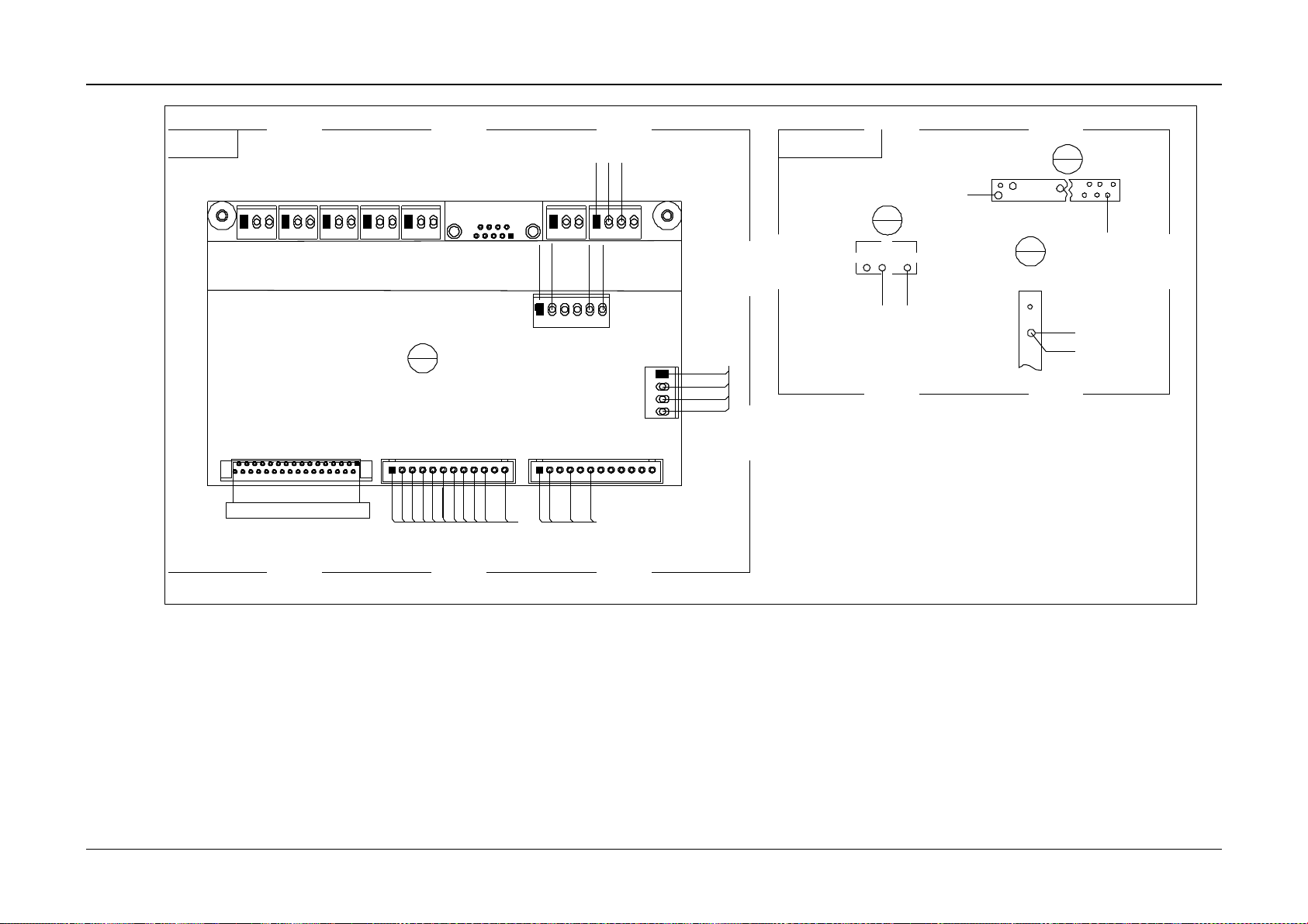
Appendix 6 Wiring Diagram 85
NetSure 731 CC2, NetSure 731 C62 Series Power Supply System User Manual
2
31
32
1
15
9
6
24
M522S
W08
W09 W09
W10 W11
W07W07
W07
BUS+
27
BUS-
28
1
2
W19
W06_3
3
SPD
25
M2433X2
-48VPE 0V
W19/W07
J1 J2 J3 J4 J5
J6
J7
J8
J9
J10
J12
J11
Temp
29-J7-2
23-1
23-2
22-1
22-2
3-1
3-2
1-1
2-1
10-1
11-1
12-1
13-1
LCD
RS232
25-0V
26-1
25-48V
47-12
47-11
液晶
50-1
50-2
25-OV
机壳
28-2
27-2
24-J8-1
24-J8-3
W18 W18 W18 W18 W18
29-J7-1
F02
F01
F04
F06
1
2
25--48v
W19
94-1
W79
15-1
Controller
Load configuration, assemble in actual configuration, process fi le and cable mark
DC lightning
protection unit
Look down at rectifier output ne gative busbar
Load configuration, assemble in actual configuration, process file and cable mark
Look down at rectifier output negative busbar
Figure 26 Wiring diagram of NetSure 731 CC2-X4 (1)
Page 92
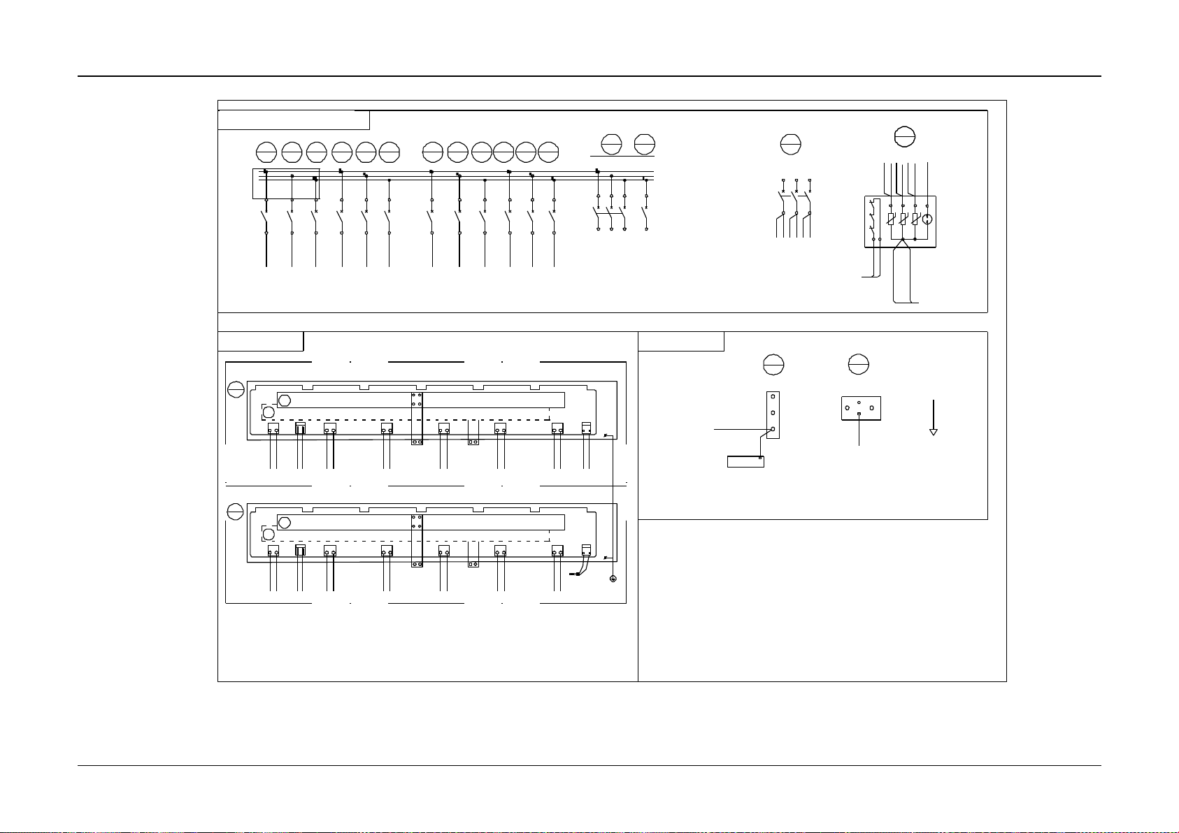
Appendix 6 Wiring Diagram 86
NetSure 731 CC2, NetSure 731 C62 Series Power Supply System User Manual
过门地线
过门地线
1
U1 V1 W1
642
1 3 5
1234561
2
43
QF4
42
QF3
45
QF1
47
SPD
48
PE
W01
2
3
W03
W06_1
2
11
2
1
212
1
2
1
2
QF5
86 87 88
80 81 82
QF6 QF7
QF11 QF12 QF13
2112
1
2
12121
2
89
QF890QF9
91
QF10
4
2
3
41
N
W02
1
QF1483QF15
84
QF16
85
W05 W 05 W05 W05 W05 W05 W05 W05 W05 W05 W05 W05
44 -2
47 -L1
47 -L2
44 -4
47 -L3
44 -6
47-PE(16mm^2)
47 -L1
47 -L2
47 -L3
29 -J1-L
(6mm^2)
47 -N1
29
W2493ZX 2
J6 J5 J4 J3 J2 J1LNJ7J8
M1
M1
W05
80 - 2
W02
29 - J1 - N
29 - J3 - N
M2
M2
DC-
DC+
29 - J5 - N
W05W 02W05W02W 05W 02W 05W0 2W05W02
LNLNLNLNLN
29 - J2 - N
J6 J5 J4 J3 J2 J1LNJ7J8
M1
M1
W05
86 - 2
87 - 2
88 - 2
89 - 2
90 - 2
W02
M2
M2
DC-
DC+
91 - 2
W05W 02
W05W02
W05W02
W05W 02
W05W 02
LNLNLNLNLN
30
W2493ZX 2
30 - J1 - N
30 - J3 - N
30 - J4 - N
30 - J5 - N
47 - N1
30 - J2 - N
30 - J2 - N
47 - N1
BUS- BUS+
BUS- BUS+
Rect.7Rect.8Rect.9Rect.10Rect.11Rect.12
Rect.1Rect.2Rec t.3Rect.4Rect.5Rect.6
Shelf 1
Shelf 2
29 -J2-L
29 -J3-L
29 -J4-L
29 -J5-L
29 -J6-L
30 -J1-L
30 -J2-L
30 -J3-L
30 -J4-L
30 -J5-L
30 -J6-L
81 - 2
82 - 2
83 - 2
84 - 2
85 - 2
29 - J2 - N
47 - N1
29 - J4 - N
47
SPD
12
PEL2L1 L3
11
W01
W09
W01W01 W01
45 -2
48 -3
45 -4
45 -6
86 -1
87 -1
88 -1
24 -J9-5
24 -J9-6
N1 N2
W02
41 -4
29 -J1-N/29 -J6-N
CAN+
CAN-
21
CAN+
CAN-
21
W09
24 - J9 - 2
24 - J9 - 1
W09
30 - J8 - 2
30 - J8 - 1
29 - J8 - 1
29 - J8 - 2
W09
CAN+
CAN-
1 2
CAN+
CAN-
1 2
29 - J6 - N
29 - J5 - N
29 - J4 - N
29 - J3 - N
47 - N1
30 - J6 - N
30 - J5 - N
30 - J4 - N
30 - J3 - N
30 -J1-N/30 -J6-N
PE
W06_4
PE
47 -L1
47 -L2
47 -L3
Front view of AC unit(Over the r ectifier
plug frame)
For nonstandard system wiring
User AC output MCB
Mains inlet cable 1
Top view of rectifier
plug frame
Battery mount panel
DC bran ch mount panel
DC bran ch mount panel
DC bran ch mount panel
AC public sector unit
AC m ount panel
Rack
Upper negative busbar
Upper negative busbar
Lower positive busbar
Lower positive busbar
Upper door
Cabinet
Neutral line busbar
Front view of AC unit (Over the rectifier
plug frame)
Figure 27 Wiring diagram of NetSure 731 CC2-X4 (2)
Page 93
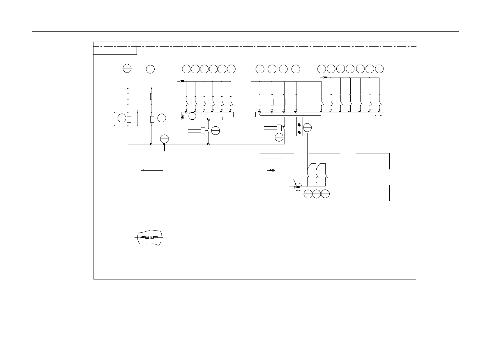
Appendix 6 Wiring Diagram 87
NetSure 731 CC2, NetSure 731 C62 Series Power Supply System User Manual
FU2FU1
10 11
22
KMD1
2
FUB2
1
RB1
3
FUB1
1
2
1
2
1
2
2
1
121
2
4
QFD1 QFD4
7
23
KMD2
2
1
26
DC-
1
W07
24-J10-3
24-J10-4
24-J10-2
24-J10-1
W08
W08
W08
24-J11-1
24-J11-2
W10
24-J11-5 24-J11-6
W10
W10
W10
1
2
24-J11-3
24-J11-4
RB2
50
1
2
17
1
2
FU312FU4
13
BLVD1
46
1
2
16
9294 93
24-J8-2
24-J11-7
24-J11-8
24-J11-9
24-J11-10
Ⅰ
插头对接情况
1 6
W06_2
2
1
5
QFD2
6
QFD3
21212
1
QFD6
QFD5
8 9 15
212
1
18
2
1
19
2
1
20
2
1
12121
2
BUS-
F01
W11
W11
F02
W11
F04
W12
Ⅰ
QFD1
21
212
1
QFD2 QFD3 QFD4 QFD5 QFD6 QFD7
2
1
27
BUS-
W13
W11
F06
QFD8QFD9
QFD10
212
1
W79
24-J11-12
W12
DC distribution front view(door open)
Battery 1 Battery 2
Enclosure
DC mount panel
DC distributor
extention unit
See description 2
Remove the monitoring board(W10 , W11 ) R emove the monitoring boa rd(W10, W11 )
Notes:
1. Connect W11 to W12 and W13, s ee the diagram for wiring sequen ce.
2. Strap the remaining connector s according to the technological requirements. Do not remove the insulation conduit.
(door open)
1. Connect W11 to W12 and W13, see the diagram for wiring sequence.
2. Strap the remaining connectors according to the technological requirements. Do not remove the insulation conduit.
Plug connection situation
Figure 28 Wiring diagram of NetSure 731 CC2-X4 (3)
 Loading...