

Page 1

NetSure 731 A41 插框电源系统
用户手册
NetSure 731 A41 Subrack Power
System
User Manual
资料版本 V1.1
归档日期 2017-12-31
BOM 编码 31013139
Version V1.1
Revision date December 31, 2017
BOM 31013139
维谛技术有限公司为客户提供全方位的技术支
持,用户可与就近的维谛技术有限公司办事处
或客户服务中心联系,也可直接与公司总部联
系。
维谛技术有限公司
版权所有,保留一切权利。内容如有改动,恕
不另行通知。
维谛技术有限公司
地址:深圳市南山区学苑大道 1001 号南山智园
B2 栋
邮编:518055
公司网址:www.vertivco.com
客户服务热线:4008876510
E-mail:[email protected]
Vertiv Tech provides customers with technical
support. Users may contact the nearest Vertiv
local sales office or service center.
Copyright © 2017 by Vertiv Tech Co., Ltd.
All rights reserved. The contents in this document
are subject to change without notice.
Vertiv Tech Co., Ltd.
Address: Block B2, Nanshan I Park, No.1001
Xueyuan Road, Nanshan District, Shenzhen,
518055, P.R.China
Homepage: www.vertivco.com
E-mail: [email protected]
Page 2

Page 3
Safety Precautions
To reduce the chance of accident, please read the safety precautions very carefully before operation. The
"Caution, Notice, Warning, Danger" in this book do not represent all the safety points to be observed, and are
only supplement to various safety points. Therefore, the installation and operation personnel must be strictly
trained and master the correct operations and all the safety points before actual operation.
When operating Vertiv products, the safety rules in the industry, the general safety points and special safety
instructions specified in this book must be strictly observed.
Electrical Safety
I. Hazardous voltage
Danger
Some components of the power system carry hazardous voltage in operation. Direct contact or indirect contact through
moist objects with these components will result in fatal injury.
Safety rules in the industry must be observed when installing the power system. The installation personnel must
be licensed to operate high voltage and AC power.
In operation, the installation personnel are not allowed to wear conductive objects such as watches, bracelets,
bangles, rings.
When water or moisture is found on the Subrack, turn off the power immediately. In moist environment,
precautions must be taken to keep moisture out of the power system.
"Prohibit" warning label must be attached to the switches and buttons that are not permitted to operate during
installation.
Danger
High voltage operation may cause fire and electric shock. The connection and wiring of AC cables must be in compliance
with the local rules and regulations. Only those who are licensed to operate high voltage and AC power can perform high
voltage operations.
II. Tools
Warning
In high voltage and AC operation, special tools must be used. No common or self-carried tools should be used.
III. Thunderstorm
Danger
Never operate on high voltage, AC, iron tower or mast in the thunderstorm.
In thunderstorms, a strong electromagnetic field will be generated in the air. Therefore the equipment should be
well earthed in time to avoid damage by lightning strikes.
Page 4
IV. ESD
Notice
The static electricity generated by the human body will damage the static sensitive elements on PCBs, such as large-scale
ICs. Before touching any plug-in board, PCB or IC chip, ESD wrist strap must be worn to prevent body static from
damaging the sensitive components. The other end of the ESD wrist strap must be well earthed.
V. Short circuit
Danger
During operation, never short the positive and negative poles of the DC distribution unit of the system or the non-grounding
pole and the earth. The power system is a constant voltage DC power equipment, short circuit will result in equipment
burning and endanger human safety.
Check carefully the polarity of the cable and connection terminal when performing DC live operations.
As the operation space in the DC distribution unit is very tight, please carefully select the operation space.
Never wear a watch, bracelet, bangle, ring, or other conductive objects during operation.
Insulated tools must be used.
In live operation, keep the arm muscle tense, so that when tool connection is loosened, the free movement of
the human body and tool is reduced to a minimum.
VI. Dangerous energy
Warning
More than 240VA system capacity, keep away from hazardous energy and avoid bridge connection.
Battery
Danger
Before any operation on battery, read carefully the safety precautions for battery transportation and the correct battery
connection method.
Non-standard operation on the battery will cause danger. In operation, precautions should be taken to prevent
battery short circuit and overflow of electrolyte. The overflow of electrolyte will erode the metal objects and PCBs,
thus causing equipment damage and short circuit of PCBs.
Before any operation on battery, pay attention to the following points:
Remove the watch, bracelet, bangle, ring, and other metal objects on the wrist.
Use special insulated tools.
Use eye protection device, and take preventive measures.
Wear rubber gloves and apron to guard against electrolyte overflow.
In battery transportation, the electrode of the battery should always be kept facing upward. Never put the battery
upside down or slanted.
Page 5
Battery installation requires reliable grounding. And battery is connected before accessing the battery protection
device.
Others
I. Sharp object
Warning
When moving equipment by hand, protective gloves should be worn to avoid injury by sharp object.
II. Cable connection
Notice
Please verify the compliance of the cable and cable label with the actual installation prior to cable connection.
III. Binding the signal lines
Notice
The signal lines should be bound separately from heavy current and high voltage lines, with binding interval of at least
150mm.
Page 6

Page 7

Contents
Chapter 1 Overview ............................................................................................................................................................ 1
1.1 Composition and Configuration ............................................................................................................................. 1
Chapter 2 Installation Instruction ......................................................................................................................................... 3
2.1 Safety Regulation .................................................................................................................................................. 3
2.2 Preparation ........................................................................................................................................................... 3
2.3 Mechanical Installation .......................................................................................................................................... 4
2.4 Electrical Installation ............................................................................................................................................. 6
2.4.1 Power System Cabling Method ................................................................................................................. 6
2.4.2 Connecting AC Cables .............................................................................................................................. 7
2.4.3 Connecting Load Cables ........................................................................................................................... 7
2.4.4 Connecting Battery Cables ........................................................................................................................ 8
2.4.5 Connecting Signal Cables ......................................................................................................................... 8
Chapter 3 Commissioning ................................................................................................................................ ................. 15
3.1 Installation Check and Startup ............................................................................................................................ 15
3.2 Basic Settings ..................................................................................................................................................... 16
3.3 Alarm Check And System Operation Status Check ............................................................................................ 17
3.4 Final Steps .......................................................................................................................................................... 18
Chapter 4 Troubleshooting ................................................................................................................................................ 19
4.1 Controller Alarms And Fault Handling ................................................................................................................. 19
4.2 Rectifier Fault Handling ....................................................................................................................................... 22
4.2.2 Rectifier Fan Replacement ...................................................................................................................... 24
Appendix 1 Technical And Engineering Data .................................................................................................................... 26
Appendix 2 Installation Instruction Of Battery Rack .......................................................................................................... 29
1. Installation Instruction Of Two-Layer And Four-Layer Battery Rack ..................................................................... 29
2. Installation Instruction Of Three-Layer Battery Rack ............................................................................................. 31
3. Fixing The Battery Rack ........................................................................................................................................ 32
Appendix 3 Wiring Diagram ............................................................................................................................................... 33
Appendix 4 Schematic Diagram ........................................................................................................................................ 35
Page 8

Page 9
Chapter 1 Overview 1
NetSure 731 A41 Subrack Power System User Manual
Chapter 1 Overview
This chapter introduces model composition and configuration and features of NetSure 731A41-S1 and NerSure
731A41-S2 (abbreviated as 'power system' hereinafter).
1.1 Composition and Configuration
Composition
The power system is composed of power distribution、rectifier modules and controller module.
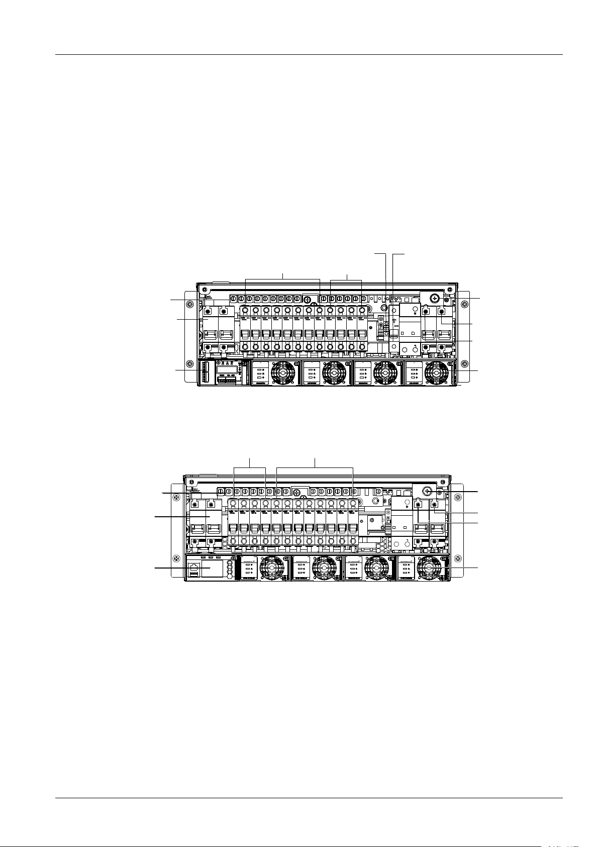
Take NetSure731A41-S1 for example, the internal structure is shown as Figure 1-1.
Positive terminal
Battery MCB
Controller
Rectifier
AC input terminal N
AC input terminal L
Earthing screw
AC output terminal L
AC output terminal N
Non-prority load
Prority load
Figure 1-1 NetSure 731 A41- S1/S2 system instruction
The internal structure of NetSure731A41-S8 is as shown in Figure 1-3.
监控模块
电池空开
正接线端子
重要负载(PL) 非重要负载(NPL)
接地螺钉
整流模块
交流输入N
交流输入L
Prority load
Non-proity load
Positive terminal
Battery MCB
Controller
Earthing screw
AC input terminal N
AC input terminal L
Rectifier
Figure 1-1 NetSure 731 A41- S8 system instruction
Page 10
2 Chapter 1 Overview
NetSure 731 A41 Subrack Power System User Manual
Configuration
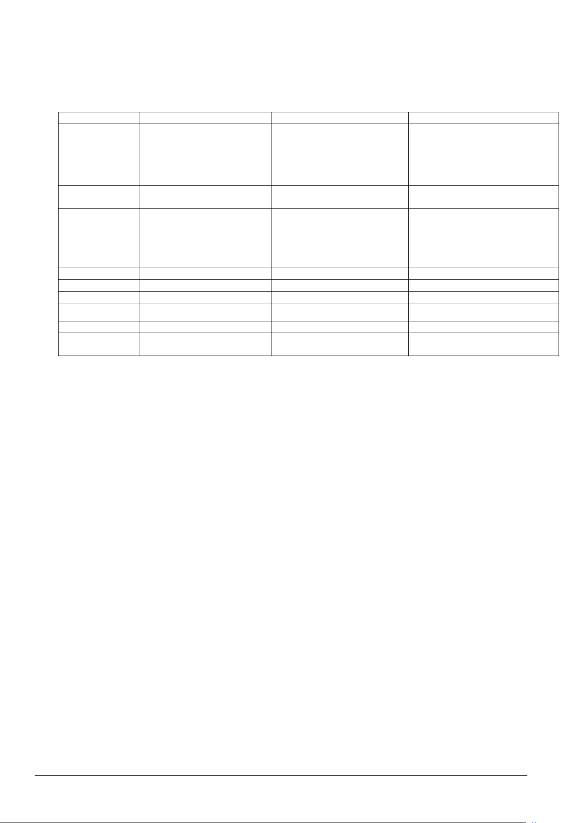
The configuration of the power system is listed in Table 1-1.
Table 1-1 Configuration of power system
Item
NetSure 731 A41-S1
NetSure 731 A41-S2
NetSure 731 A41-S8
Controller
Model:M225S
Model:M221S/M222S
Model:M830B
Rectifier
Model:
R48-3000e3 or R48-3000A3
Maximum configuration:4 pieces
Model:
R48-3000e3 or R48-3000A3
Maximum configuration:4 pieces
Model:
R48-3000e3 or R48-3000A3 or
R48-3500e3
Maximum configuration:4 pieces
AC power
distribution
L+N+PE/220Vac
L+N+PE/220Vac
L+N+PE/220Vac
DC power
distribution
PL:
32A/1P×2;16A/1P×2 MCB
NPL:
63A/1P×2;32A/1P×4;16A/1P×2
MCB
PL:
32A/1P×2;16A/1P×2 MCB
NPL:
63A/1P×2; 32A/1P×4;16A/1P×2
MCB
PL:
32A/1P×2;16A/1P×2 MCB
NPL:
63A/1P×2; 32A/1P×4;16A/1P×2 MCB
AC output MCB
1×16A/1P
1×16A/1P
NA
Battery MCB
2×125A/1P
2×125A/1P
2×125A/1P
AC SPD
1 piece
1piece
1piece
DC SPD
1piece
1piece
1piece
Cover
Optional
Optional
Optional
BLVD controller
control mode
Controller power-losing mode
Controller power-losing mode
Controller power-losing mode
Main Features
The rectifier uses the active Power Factor Compensation(PFC) technology and the power factor is up to 0.99.
The power system has wide AC input voltage: 85Vac~300Vac.
The rectifier uses soft switching technology, raising the efficiency above 95.5%.
The rectifier has Ultra-low radiation. With advanced EMC design, the rectifier meets international standards such
as CE、NEBS and YD/T983.Both the conducted and radiated interference reach Class B.
The rectifier safety design complies UL,CE and NEBS.
The rectifier is of high power density.
The rectifier is hot pluggable. It takes less than1 min to replace a rectifier.
The rectifier has two optional over-voltage protection methods: hardware protection and software protection. The
latter one also has two optional modes: lock-out at the first over-voltage and lock-out at the second
over-voltage.
The controller module has perfect battery management. The management functions includes BLVD,
temperature compensation, auto voltage regulation , stepless current limiting ,battery capacity calculation and
on-line battery test, etc.
History alarm records:M221S/M222S controller supports 200 history alarms and 1000 history data records,
M225S controller supports 200 history alarms and 512 history data records. And M820B/M830B supports
historical alarm record up to 3000 pcs and historical record up to 60000 pcs.
Battery test data: can record up to 10 sets of battery test data.
The power system is of network design. Providing multiple communication ports (such as RS232, modem and
dry contacts), which enables flexible networking and remote monitoring.
The power system has perfect lighting protection at both AC side and DC side.
The power system has complete fault protection and fault alarm functions.
The power system uses " controller power-losing " control mode . In the indoor or outdoor equipment room
without guard and maintenance, the " controller power- losing mode" can protect the battery from deep
discharge.
Page 11
Chapter 2 Installation Instruction 3
NetSure 731 A41 Subrack Power System User Manual
Chapter 2 Installation Instruction
2.1 Safety Regulation
Certain components in this power system carry hazardous voltage and current. Always following the instructions
below:
1.Only the adequately trained personnel with satisfactory knowledge of the power system can carry out the
installation. The most recent revision of these safety rules and local safety rules in force shall be adhered to during
the installation.
2.All external circuits that are below 48V and connected to the power system must comply with the requirements of
SELV as defined in IEC 60950.
3.Make sure that the power (mains and battery) to the system is cut off before any operations can be carried out
within the system cabinet.
4.The power cabinets shall be kept locked and placed in a locked room. The key keeper should be the one
responsible for the power system.
5.The wiring of the power distribution cables should be arranged carefully so that the cables are kept away from the
maintenance personnel.
2.2 Preparation
Unpacking inspection
The equipment should be unpacked and inspected after it arrives at the installation site. The inspection shall be done
by representatives of both the user and Vertiv Tech Co., Ltd.
To inspect the equipment, you should open the packing case, take out the packing list and check against the packing
list that the equipment is correct and complete. Make sure that the equipment is delivered intact.
Cables
The cable should be selected in accordance with relevant industry standards.
It is recommended to use the RVVZ cables as AC cables. The cable should reach at least +70°C temperature
durability. With cable length shorter than 30 meters, the Cross-Sectional Area (CSA) calculation should be based on
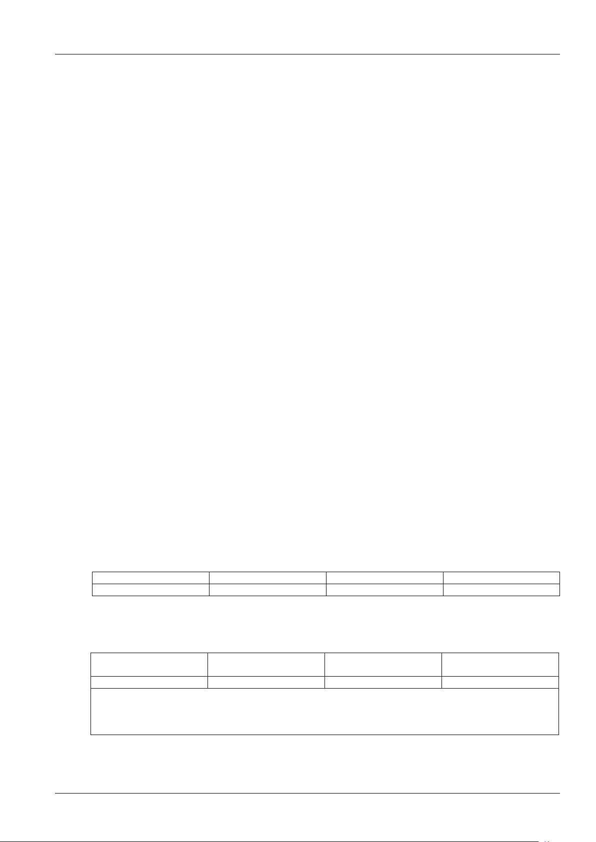
the current density of 3.5A/mm2. The suggested CSA value is no less than the Table 2-1.
Table 2-1 AC cable CSA selection
AC MCB rated current
Max. AC input current
Min cable CSA
Max cable CSA
125A
74A
25mm2
50mm2
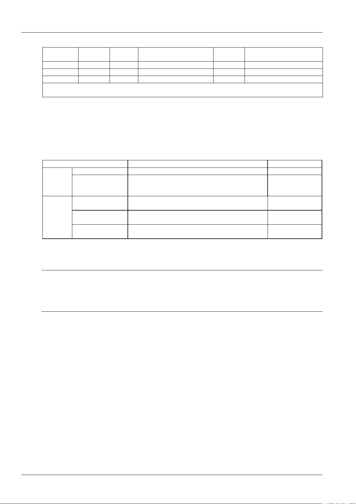
The CSA of DC cable depends on the current flowing through the cable and the allowable voltage drop. To select the
battery cable CSA, see Table 2-2,select the DC load cable CSA according to the Table 2-3.
Table 2-2 Battery cable CSA selection
Battery MCB rated current
Max. battery current
Min cable CSA
Max cable length( volt drop:
0.5V with max. CSA)
125A
105A
35mm2
6m
Note:
1. The specs are applicable at ambient temperature of 25°C.
2. The battery cable should reach at least +90°C heat durability. It is recommended to use double-insulated copper-core flame
retardant cable as battery cable.
Page 12
4 Chapter 2 Installation Instruction
NetSure 731 A41 Subrack Power System User Manual
Table 2-3 DC load cable CSA selection
Load route
rated current
Max. output
current
Min. cable
CSA
Max cable length ( volt drop: 0.5V
with min. CSA)
Max. cable
CSA
Max cable length ( volt drop: 0.5V
with max. CSA)
63A
50A
16mm2
9m
25mm2
14m
32A
25A
10mm2
11m
25mm2
29m
16A
12A
6 mm2
14m
25mm2
48m
Note: The specs are applicable at ambient temperature of 25°C. If the temperature is higher than this, the CSA of the cable should
be increased.
To prevent the air switching capacity is too large, the load doesn't work when overload. Recommended the capacity
of the air switching is up to 1.5~2 times of the load peak.
The CSA of the system grounding cables should be consistent with the largest power distribution cables. The CSA
value is no less than 25mm2.
AC distribution、DC distribution interface definition see Table 2-4.
Table 2-4 AC distribution、DC distribution interface definition
Connector name
Connector specifications
Wiring instruction
AC power
distribution
AC input MCB
H type terminal, max. cable CSA 50mm2
AC power line
Grounding busbar
One M8 bolt, OT type wiring terminal, max. cable CSA 35mm2
Connected to the
grounding bar of the
building
DC power
distribution
Battery output MCB
H type terminal, max. cable CSA 50mm2
Connected to the
battery port
Negative output MCB
H type terminal, max. cable CSA 25mm2
Connected to the users
negative load port
Positive busbar
Terminal subrack terminal:cable CSA ≤ 50mm2
Connected to the users
positive load port
2.3 Mechanical Installation
Note
1. The cabinet or rack that installed in the subrack must provide fireproof and electric protection casing, or install in cement or
other difficult to burn, at the same time keep enough distance to other combustible material.
2. For the convenience of maintenance, users should maintain a clearance of 800mm at the front of the power system.
3. Subrack cannot be installed against the wall, it must leave enough space for heat dissipation.
Installed on the battery rack
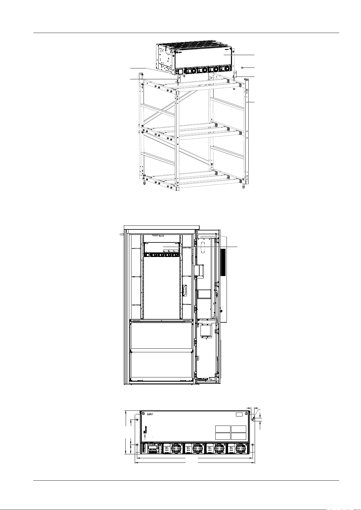
Fix the subrack power system to the battery rack through the connectors with M6 bolts, as show in Figure 2-1.
Page 13
Chapter 2 Installation Instruction 5
NetSure 731 A41 Subrack Power System User Manual
Connector
M6 screw
Subrack
power system
Connector
M6 screw
Battery bracket
Battery rack
Power system
Figure 2-1 Cabinet and rack installation
Installed in cabinet
Insert the subrack power system to the matching cabinet, as shown in Figure 2-2.
电源插框
Power subrack
Figure 2-2 Installed in the cabinet system
The engineering graphics of the subrack power system as shown in Figure 2-3.
101.6
177.0
37.7
465.1
482.6
7.0
R3.5
10.0
Figure 2-3 Installation size of NetSure 731 A41(unit::mm)
Page 14
6 Chapter 2 Installation Instruction
NetSure 731 A41 Subrack Power System User Manual
Note
1. Tighten the captive screw of the MFU Panel by the cross head screwdriver when there is no operation.
2. Also tighten the handle by the cross head screwdriver.
3. Please plug in the new modules or installing a new panel after removing the rectifier module.
2.4 Electrical Installation
2.4.1 Power System Cabling Method
Cabling from the top of the power system
Epoxy board top cover and rubber ring top cover are optional for this system.
Note
If the user requires the system to meet the CE certification, install the epoxy board top cover to be installed at a distance of 1.8
meters high above the ground.
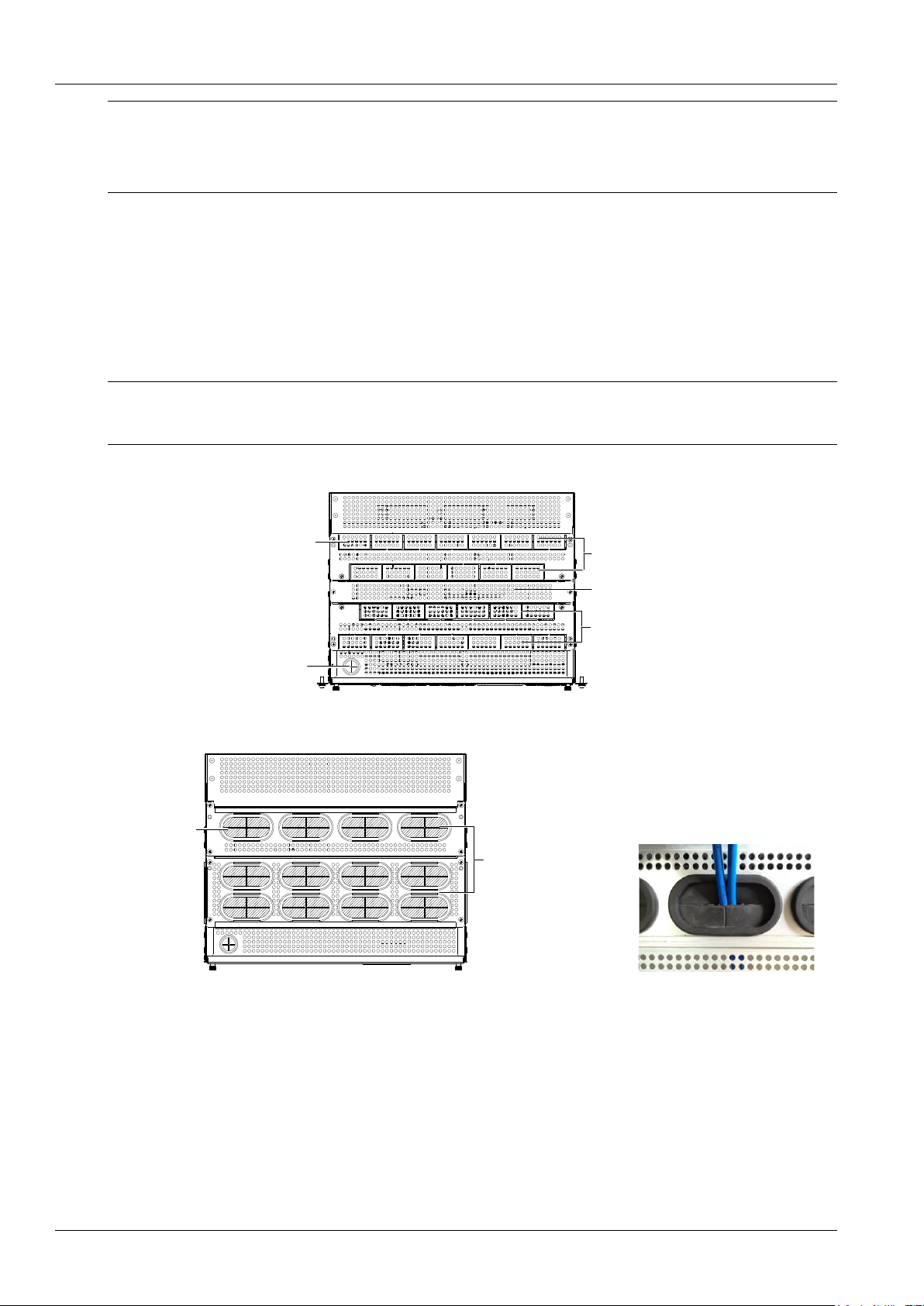
Epoxy board top cover for MFU unit cabling. As shown in the Figure 2-4.
Cable outlet area
Cable-bundling plate
Signal cable
outlet holes
Cable outlet area
Square unit
Figure 2-4 Cable entry illustration of the MFU unit
Rubber ring top cover for MFU unit cabling as shown in Figure 2-5.
Cable outlet area
Latex unit
Figure 2-5 Cable entry illustration of the MFU unit
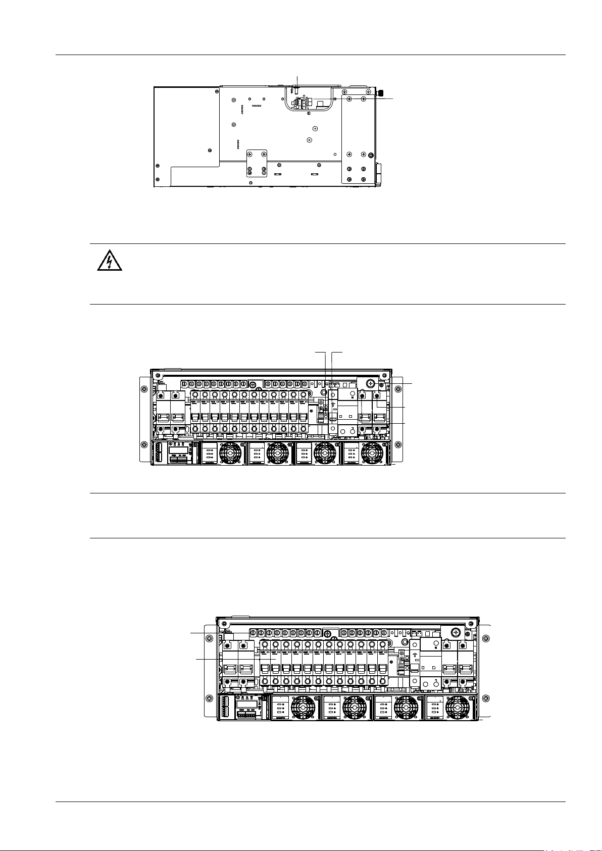
Cabling from side of the power system
Use a cross head screwdriver to remove two screws which fix the cabling panel at side of cabling area, then the cable
can be led out from the cabling area, as shown in Figure 2-6.
Page 15
Chapter 2 Installation Instruction 7
NetSure 731 A41 Subrack Power System User Manual
Screw
Cable-bunding plate
(cabling area)
Figure 2-6 Side cabling illustration
2.4.2 Connecting AC Cables
Danger
Danger
1. Switch off all MCBs and fuses before the electrical connection.
2. Only the qualified personnel shall do the power cable connection.
Take the NetSure 731 A41-S1power system for example, the position of the connection terminals are shown in
Figure 2-7.
AC output terminal N
Earthing screw
AC output terminalL
AC output terminalL
AC output terminal N
Figure 2-7 Illustration of the connection terminal
Note
1. Recommended tightening torque of user grounding screw is 10.78N*M.
2. In case system earthing cable lessen, please add another fixing point except for the earthing screw.
2.4.3 Connecting Load Cables
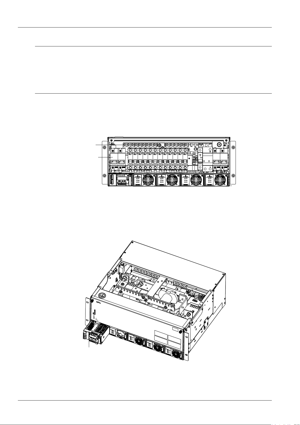
Connect the negative load cable to the upper terminal of load MCB and then connect the positive load cable to
positive terminal. As shown in Figure 2-8.
Positive terminal
Load MCB
Figure 2-8 Illustration of the load connection terminal
Page 16
8 Chapter 2 Installation Instruction
NetSure 731 A41 Subrack Power System User Manual
2.4.4 Connecting Battery Cables
Note
1. The batteries may have dangerous current. Before connecting battery cables, make sure that the battery MCBs at the battery
side are switched off.
2. If there are no battery MCBs at the battery side, users should disconnect any one of the connectors between battery cells to
avoid live state of the system after installation.
3.Be careful not to reversely connect the battery. Otherwise, both the battery and the system will be damaged.
4.It's forbidden to disassemble battery cables in the up of the battery MCB when the battery input port is still connected.
1. Connect one end of the negative battery cable to the upper terminal of battery MCBs. Connect one end of the
positive battery cable to the DC positive bus bar.
2. Connect copper lugs to the other end of the battery cables. Bind the connecting parts with insulating tape, and put
them beside the battery. Connect the cables to the battery when the DC distribution unit is to be tested. As shown in
Figure 2-9.
Positive terminal
Battery MCB
Figure 2-9 Illustration of the battery connection terminal
2.4.5 Connecting Signal Cables
Connecting NetSure 731 A41-S1 Signal Cables
The standard configuration of the system is M225S controller. The M225S1X1 user interface board is used for
M225S.M225S controller and M225S1X user interface board cable connection is show in the following:
Interface board
Figure 2-10 NetSure 731 A41-S1 user interface board position illustration
M225S controller provides two dry contact alarm output ports: DO1 and DO2. DO2 is for LLVD in subrack system. If
LLVD is selected, it can't be used for dry contact and should be sealed by white tape when out of the factory . If LLVD
Page 17
Chapter 2 Installation Instruction 9
NetSure 731 A41 Subrack Power System User Manual
is not selected, It can be used for dry contact. NetSure 731 A41-S1 provides four extended dry contacts: DO3、DO4、
DO5 and DO6,the illustration is as shown in the following:
3
4
5 6
Figure 2-11 M225S1X1usr interface board illustration
Digital output dry contact specification of M225S controller and M225S1X1user interface board is as following:
Digital output:relay isolation,max:30Vdc 1A,125Vac 0.5A,60W;Min:10uA@10Vdc.
The dry contacts definition of M225S controller and M225S1X1 user interface board is shown in Table 2-5.
Table 2-5 Dry contact definition
Type
Default alarm
Description
DO1
Major alarm
/
DO2
Load disconnection control
LLVD control, user can't use it when LLVD is selected.
DO3
AC failure.
DO4
DC overvoltage or DC undervoltage
DO5
Rectifier alarm
Except rectifier lost and multi-rectifier alarm.
DO6
Battery protection and load disconnection alarm.
In the controller normal state, the alarm contacts are always open, when system issues above alarms, related
contacts will be closed. All the status changes should be verified by a multimeter. After the alarms are removed, the
dry contacts (DO) should back to the open state.
Connecting NetSure 731 A41-S2 Signal Cables
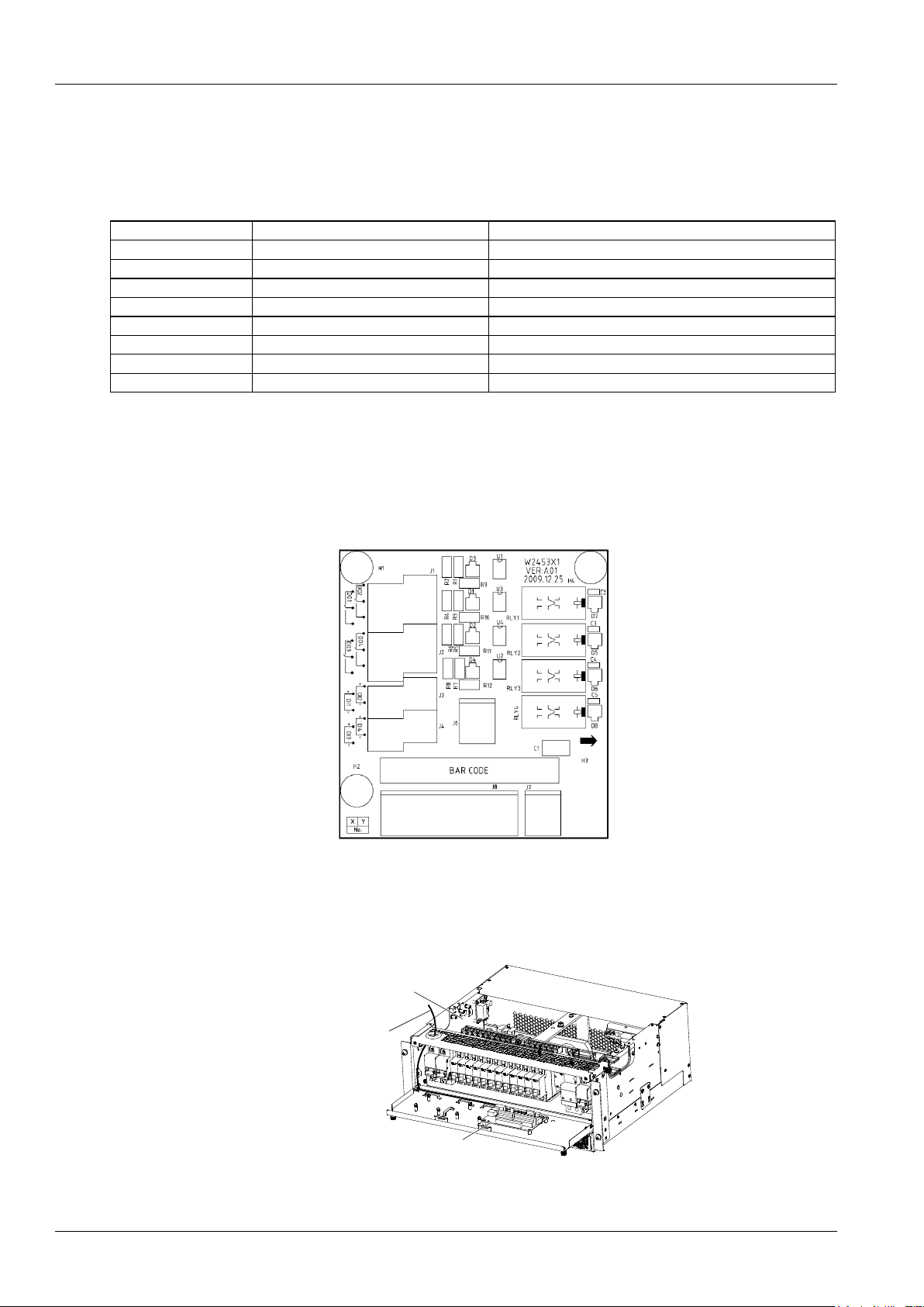
W2453X1 user interface board provides dry contacts for NetSure 731 A41-S2.W2453X1 user interface board position
and signal cabling as shown in Figure 2-12.
信号电缆
用户接口板
用户接口板
(柔性配置)
Signal cable
User interface board
User interface board
(Flexible configuration)
Figure 2-12 NetSure 731 A41-S2 user interface board illustration
At most two W2453X1 user interface boards are allowed in the power system. Standard cabinet is only configured
with one user interface board.
With one W2453X1 user interface board configured, the power system provides four external digital input ports: DI1,
DI2,DI3,DI4 and four dry contact alarm output ports
With two user interface boards configured, the power system provides additional four dry contact alarm output
interfaces: DO5,DO6,DO7,DO8.
Page 18
10 Chapter 2 Installation Instruction
NetSure 731 A41 Subrack Power System User Manual
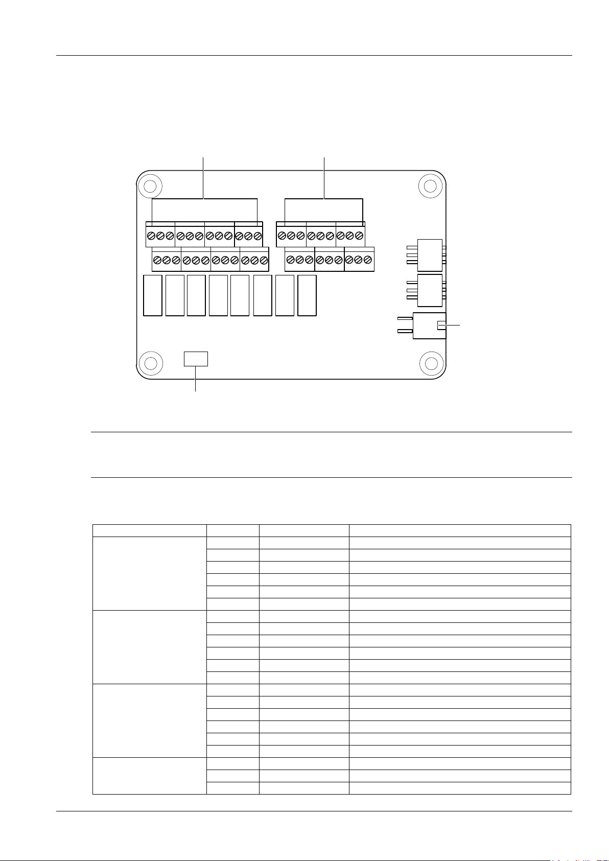
The digital input ports of W2453X1 user interface board needs to connect active dry contact. Dry contact spec as
following:
Digital output: relay isolation, Max.:30Vdc/1A, 125Vac/0.5A, 60W; Min.: 10uA@10Vdc, alarm is definable.
The functions of the interfaces are shown in Table 2-6.
Table 2-6 Dry contacts definition
Type
Default alarm
Description
Dry contact 1
AC power failure
/
Dry contact 2
DC overvoltage or DC undervoltage
Four-level DC voltage alarms
Dry contact 3
Rectifier alarm
Except rectifier lost and multi-rectifier alarm
Dry contact 4
Priority LLVD
/
Dry contact 5
Non-priority LLVD
Exist when the second user interface board is installed
Dry contact 6
/
Exist when the second user interface board is installed
Dry contact 7
/
Exist when the second user interface board is installed
Dry contact 8
/
Exist when the second user interface board is installed
With default settings, when the preceding alarms are generated, the contactors of the corresponding dry contacts
should change their status. That is, the normally-open contactors close, and the normally-closed contactors open. All
the status changes should be verified by a multimeter. After the alarms are removed, the dry contacts (Do) should
back to the original state.
Dry contact definition is settable in the controller, please refer to M221S Controller User Manual.
The user interface board illustration is as shown in the following:
Figure 2-13 W2453X1 user interface board illustration
Connecting NetSure 731 A41-S8 Signal Cables
The communication port of the M830B controller is shown in Figure 2-18.
用户接口板
(DI/DO板 )
信号线缆
RS485端子
User interface board
User interface board
(DI/DO board)
RS485 terminal
Figure 1-2 Communication port of M830B controller
Page 19
Chapter 2 Installation Instruction 11
NetSure 731 A41 Subrack Power System User Manual
IB2 user interface board
The external input and output signals are all connected to the IB2 user interface board. For the ports on the IB2 user
interface board, see Figure 2-15.
J9 J8 J7 J6 J5 J4
J12
J11
J2
Digital inputs 1~ 8,
20V ~ 60V
I C port
2
SW1
Address DIP
J3
Alarm output dry contact
.
Figure 1-1 IB2 extension board port definition
Note
1. J11 and J12 are temperature sensor ports. They are not used here.
2. J2 is I2C interface, and provides the power.
See Table 2-6 for the dry contact terminal definition.
Table 1-1 Dry contact terminal definition
Name of double-layer port
Pin No.
Pin name
Definition
J3
1
DI1-
Digital input 1-
2
DI1+
Digital input 1+
3
DI2-
Digital input 2-
4
DI2+
Digital input 2+
5
DI3-
Digital input 3-
6
DI3+
Digital input 3+
J4
1
DI4-
Digital input 4-
2
DI4+
Digital input 4+
3
DI5-
Digital input 5-
4
DI5+
Digital input 5+
5
DI6-
Digital input 6-
6
DI6+
Digital input 6+
J5
1
DI7-
Digital input 7-
2
DI7+
Digital input 7+
3
DI8-
Digital input 8-
4
DI8+
Digital input 8+
5
NA / 6
NA
/
J6
1
DO1_NC
NC contact of relay 1
2
DO2_NC
NC contact of relay 2
3
DO1_COM
Common contact of relay 1
Page 20
12 Chapter 2 Installation Instruction
NetSure 731 A41 Subrack Power System User Manual
Name of double-layer port
Pin No.
Pin name
Definition
4
DO2_COM
Common contact of relay 2
5
DO1_NO
NO contact of relay 1
6
DO2_NO
NO contact of relay 2
J7
1
DO3_NC
NC contact of relay 3
2
DO4_NC
NC contact of relay 4
3
DO3_COM
Common contact of relay 3
4
DO4_COM
Common contact of relay 4
5
DO3_NO
NO contact of relay 3
6
DO4_NO
NO contact of relay 4
J8
1
DO5_NC
NC contact of relay 5
2
DO6_NC
NC contact of relay 6
3
DO5_COM
Common contact of relay 5
4
DO6_COM
Common contact of relay 6
5
DO5_NO
NO contact of relay 5
6
DO6_NO
NO contact of relay 6
J9
1
DO7_NC
NC contact of relay 7
2
DO8_NC
NC contact of relay 8
3
DO7_COM
Common contact of relay 7
4
DO8_COM
Common contact of relay 8
5
DO7_NO
NO contact of relay 7
6
DO8_NO
NO contact of relay 8
The definition of dry contact function can be set through controller or the WEB browser.
The specifications of the dry contact ports are as follows:
Digital inputs: 8-route, opto-isolation, the alarm and high/low level are definable (high level: 20V ~ 60V, low level: less
than 1V).
Digital output: 8-route, relay isolation, maximum: 30Vdc 1A, 125Vac 0.5A; 60W; minimum: 10uA @ 10Vdc, alarm is
definable.
Connecting Communication Signal Cable
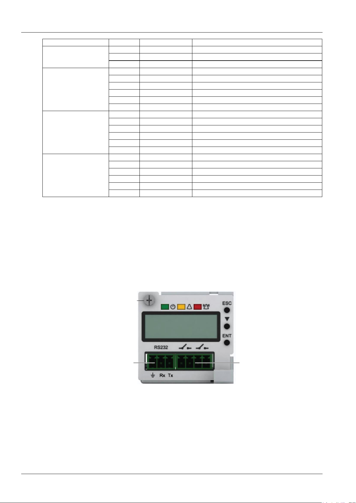
The RS232 communication port of M225S controller is shown in Figure 2-14.
RS232 communication
serial port
Dry contact output
Figure 2-14 M225S controller communication port
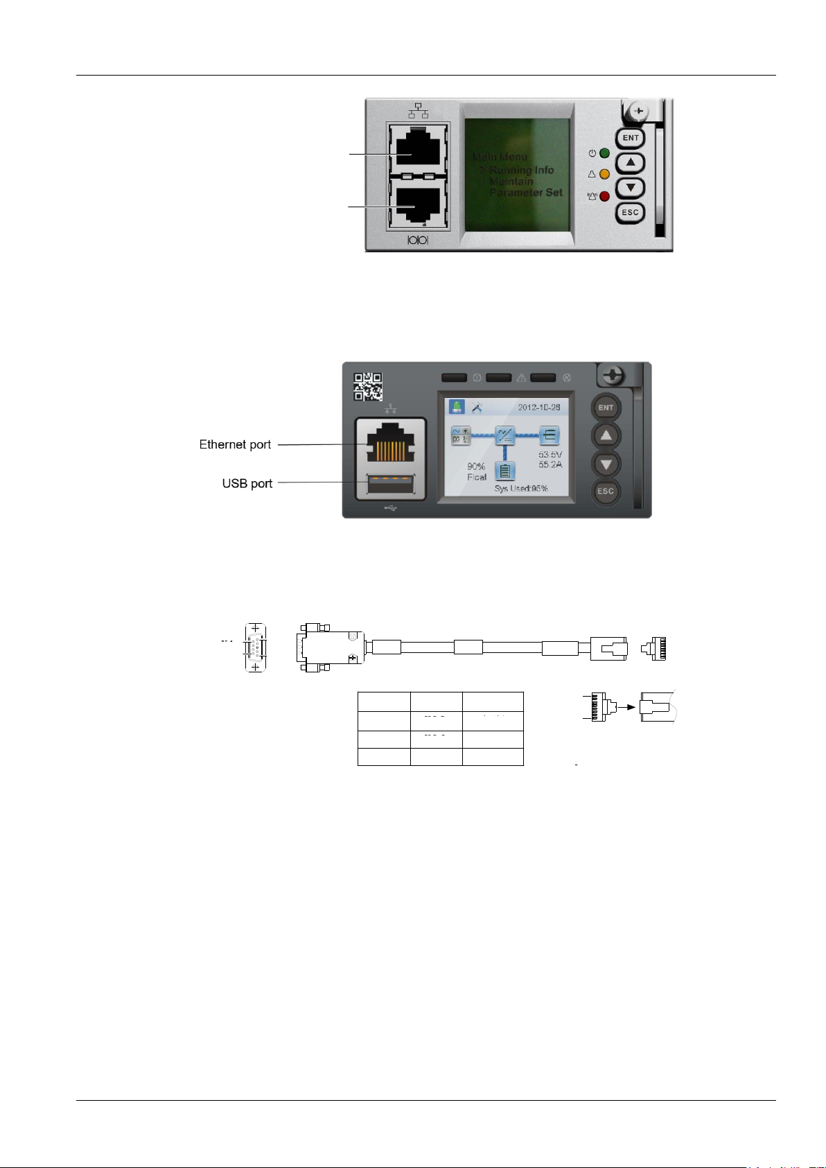
The communication port of the M221S controller is shown in Figure 2-15.M222S only provides the RS232
communication serial port, whereas the Ethernet port is not provided.
Page 21
Chapter 2 Installation Instruction 13
NetSure 731 A41 Subrack Power System User Manual
以太网口
RS232通讯串口
RS232 communication
serial port
Ethernet port
Figure 2-15 M221S controller communication port
The communication port of the M830B controller is shown in Figure 2-16.
Figure 2-16 M830B controller communication port
Please refer to Figure 2-17 to make communication signal cables.
1
5
6
9
X1 X2
1
8
A
接线表
X2X1 颜色
X1.2
X1.3
X1.5
X2.3
X2.6
X2.5
白/绿
绿
白/蓝
Wiring table
X1
X2
X1.2
X1.3
X1.5
X2.3
X2.6
X2.5
Colour
White/blue
Green
White/green
X1
9
6
5
1
X2
A
1
8
Figure 2-17 Communication signal cable
2.4.6 Connecting temperature compensation cable
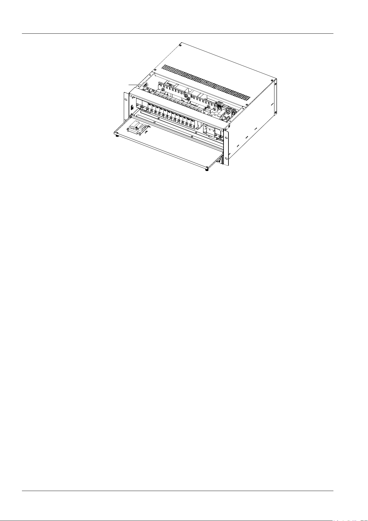
If the optional temperature compensation cable is not connected to the subrack, take down the preassembled Temp
terminal from the left side of the subrack, connect the temperature compensation cable with Temp terminal and put
the probe on the other side onto the battery. The Temp terminal is as shown in Figure 2-18
Page 22
14 Chapter 2 Installation Instruction
NetSure 731 A41 Subrack Power System User Manual
Temp terminal
Figure 2-18 The position of temp terminal
Page 23

Chapter 3 Commissioning 15
NetSure 731 A41 Subrack Power System User Manual
Chapter 3 Commissioning
The controllers can be used in the power system are M221S、M222S , M225S and M830B. The detail instructions of
the controllers please refer to the user manuals. This section introduces commissioning after installation. During
installation test, the corresponding safety rules should be adhered to. The system has been tested before out of the
factory, user doesn't need to test on site.
3.1 Installation Check and Startup
Before the test, inform the chief manufacturer representative. Only trained electrical engineer can maintain and
operate this equipment. In operation, the installation personnel are not allowed to wear conductive objects such as
watches, bracelets, bangles and rings.
During operation, parts of this equipment carry hazardous voltage. Misoperation may result in severe or fatal injuries
and property damage. Before the test, check the equipment to ensure the proper earthing. Installation check must be
done before testing. Then the batteries can be charged for the first time.
Make sure that the AC input MCBs, battery MCBs and load MCBs are switched off. Make sure that all the devices are
properly installed.
Installation check
OK
Comments
Check all the fuse and cables. Are the models correct?
Check the busbar connections, input and output cable connection, and connection between the power
system and the system grounding.
Check if the number and connections of the batteries are correct. Check the polarity of the battery string
with a voltmeter.
Make sure all the communication cables and alarm cables are connected to the controller module. Check
that the temperature sensor, if any, has been installed.
Startup preparations
OK
Comments
Make sure that all the MCB are switched off and all the fuses are removed.
Measure the AC input voltage. Make sure the input voltage is within the allowable range.
Umin= V
Check that communication and alarm cables are connected to the signal transfer board.
Check that the temperature sensor, if any, has been installed.
Check that the battery string circuit is not closed.
Connect the disconnected batteries to the battery string circuit.
Make sure that the MCB disconnected to the battery cables are switched off. Check the battery signal
cables connection and MCB cables connection.
Measure with a voltmeter across the connection points of each battery and make sure that the polarity is
right. For a lead-acid battery with 24 cells, the voltmeter should read 2.0 ~ 2.1V/cell or 48 ~ 51V/battery. If
the voltage of certain cell is lower than 2.0V, that cell must be replaced.
Umin= V
Check with an ohmmeter that there is no short circuit between the positive & negative distribution bus bars,
or between the positive & negative battery poles (Note: Pull out all modules before the check and restore
them after the check).
Startup
OK
Comments
Switch on the system AC input MCB. Insert one rectifier. The green LED on the rectifier will be on and the
fan will start running after a certain delay. The controller module will show that the power supply voltage is
53.5V( when it used for outdoor, the output voltage is 54V).
Check the system voltage and busbar polarity with a voltmeter. The voltage difference between the
measured value and displayed value should be less than±0.2V.
Start and stop each rectifier of the system by inserting and unplugging the rectifier. Check their output
voltages.
Page 24

16 Chapter 3 Commissioning
NetSure 731 A41 Subrack Power System User Manual
3.2 Basic Settings
When the system is put into service for the first time, the parameters of controller module must be set based on the
actual system configuration, such as battery number, capacity, user’s charge current limit and other functional
requirements. Only after that can the controller module display system operation information and control the output.
(M221S,M222S controller password is 2; M225S controller password is1 )
OK
Comments
The system model has been set correctly in factory before delivery, check that the setting agrees with the
actual system.
(The path to check and set of the M221S\M222S controller:SettingsBat. SettingsBasic Settings)
NetSure 731 A41-S1:48V/SET;battery shunt coefficient:300A/25mV;
(The path to check and set of the M225Scontroller:Settings Shunt A)
NetSure 731 A41-S2:battery shunt coefficient:300A/25mV
Setting controller according to number of battery groups connected. Default: two groups.
(The path to check and set of the M221S\M222S controller:SettingsBat. SettingsBasic Settings
Bat.Fuse)
(No such settings for M225S controller)
Setting controller according to the capacity of battery groups connected. Default: 300Ah
(The path to check and set of the M221S\M222S controller:SettingsBat. SettingsBasic Settings
Capacity)
(The path to check and set of the M225S controller:Settings Capacity)
Setting LVD1: default:44V(If the subrack system is used for outdoor, default setting:46.6V)
(The path to check and set of the M221S\M222S controller:SettingsBat. SettingsLVD Settings
LVD1 Volt)
(The path to check and set of the M225Scontroller:SettingsLVD1,default setting:Yes
Relay 2 settings“SettingsRelay 2”,default setting “LVD1”)
Setting LVD2: default:43.2V(If the subrack system is used for outdoor, default setting:45.6V)
(The path to check and set of the M221S\M222S controller:SettingsBat. SettingsLVD Settings
LVD2 Volt
(The path to check and set of the M225Scontroller:SettingsLVD2,)
Setting AC input type. Default value: 1-PH
(The path to check and set of the M221S\M222S controller:SettingsInput SettingsAC PH)
(No such settings for M225S controller)
Walk-in T setting: default:8S
(The path to check and set of the M221S\M222S controller:SettingsRect SettingsWalk-in on,
default“Y”
(SettingsRect SettingsWalk-in T,default“8S”)
(The path to check and set of the M225Scontroller:Settings Walk-in T,default“8S“)
Setting controller according to the battery factory.Temperature compensation range:0~500mV/℃. Default:
72mV/℃.
(The path to check and set of the M221S\M222S controller:SettingsBat.settingsTemp.Comp)
(No such settings for M225S controller)
Set the charge current limit according to your needs. Setting range: 0.1 C10~0.25C10。Default:0.1C10
(The path to check and set of the M221S\M222S controller:Settings Bat. SettingsCharge)
(No such settings for M225S controller)
Set the controller according to the voltage suggested by the battery supplier.
Float charge voltage:42V~Boost charge(BC),default:53.5V(If the subrack system is used for outdoor,
default voltage:54V);
Boost chare voltage:Float charge(FC)~58V,default:56.4V
(The path to check and set of the M221S\M222S controller:Settings Bat. SettingsCharge)
(The path to check and set of the M225Scontroller:SettingsFloat/Boost)
SettingsFloat/Boost
Set the boost charge voltage higher 0.1V than float charge voltage for the free boost charge battery.
Close the battery MCBs and connect the battery.
Page 25
Chapter 3 Commissioning 17
NetSure 731 A41 Subrack Power System User Manual
The User and password of the M830B controller is set by web, see NetSure™ Control Unit (NCU) User Manual Tabe 3-3 M830B
controller paremeter settings
Parameter
Path
Default settings
Rated Capacity
LCD/ SettingsBatt SettingsChargeBatt1 Settings
Rated Capacity
300Ah
LVD1
LCD/ Settings—LVD Settings—LVD1
Enabled
LVD2
LCD/ Settings—LVD Settings—LVD2
Enabled
LVD1 Voltage
LCD/ Settings—LVD Settings—LVD1Voltage
44.0V
LVD2 Voltage
LCD/ Settings—LVD Settings—LVD2Voltage
43.2V
AC Fail Required
Web/Settings—System—LVDGroup—AC Fail Required
Enabled
Num Batt Shunts
LCD/ Settings—Batt Settings—Basic Settings—Num
Batt Shunts
1
Shunt Current/ Shunt Voltage
LCD/ Settings—Batt Settings—Basic Settings—Batt1
Settings—Shunt Current/Shunt Voltage
300A/25mV
LVD Contactor Type
Web /Settings—LVD—LVD Contactor Type
Bistable
Walk-In
LCD/ Settings—Rect Settings—Walk-In
Enabled
Walk-In Time
LCD/ Settings—Rect Settings—Walk-In Time
128S
Note: The LVD2 voltage settings should follow battery factory's requirement and the battery capacity settings should
based on the actual configuration settings.
3.3 Alarm Check And System Operation Status Check
Alarm check
Check that all functional unit can trigger alarms that can be displayed on the controller.
OK
Comment
Pull out one rectifier. The ‘Rect N Com Failure’ alarm should be triggered. Insert the rectifier in. The alarm
should disappear. Repeat the same procedures on other rectifiers
Switch off battery MCB 1. The ‘Batt1 Failure’ alarm should be triggered. Switch on the MCB. The alarm
should be cleared. Repeat the same on battery MCB 2
Switch off a load MCB connected to a load route. The alarm ‘Load Fuse N Failure’ should be triggered.
Switch on the MCB, and the alarm should be cleared. Repeat the same on the other load MCBs
Remove all the battery MCBs. Keep only one rectifier in operation. Through the controller module, adjust
the rectifier FC voltage to make it lower than the alarm point. The alarm ‘DC Voltage Low’ should be
triggered
Keep the rectifiers in operation. Set through the controller module the battery management parameter to
‘Manual’. Enter the maintenance menu at the controller module. Select ‘Disconnect’ and confirm it. The
battery protection contactor should be open, and the ‘BLVD’ alarm should be displayed at the controller
module
Note: when the preceding alarms are generated, the controller module will give alarms after approximately
3s.
System operation status check
There should be no alarms during normal system operation. The system operation status can be conducted through
the controller module.
OK
Comments
The system model is correct.
The controller should display the correct AC voltage
The controller should be able to display the DC voltage. The difference between the displayed voltage and
that measured at the busbar should be less than 1%
The controller should diaplay the battery current. The difference between the displayed and measured
battery current should be less than 1%
Check the number of the rectifier through the controller . The number should be consistent with the actual
number.
Check the voltage, current, current limiting point of rectifiers through the controller. They should agree with
the actual parameter.
For the system configured with temperature sensor, the controller should be able to diaplay the battery
Page 26

18 Chapter 3 Commissioning
NetSure 731 A41 Subrack Power System User Manual
ambient temperature. Hold the probe of the temperature sensor with hand and watch the controller which
should display the change of temperature.
3.4 Final Steps
OK
Comments
Make sure that materials irrelevants to the equipment have been all removed.
Rehabilitate the power equipment and close the cabinet door.
Fill in the installation report and hand it over to the user.
Record all the operations in the file , including operation time and operator name.
If any defect is found in this equipment, inform the personnel responsible for the contract.
If repairing is needed, please fill in the FAILURE REPORT and send the report together with the defective unit to the
repairing center for fault analysis.
Page 27
Chapter 4 Troubleshooting 19
NetSure 731 A41 Subrack Power System User Manual
Chapter 4 Troubleshooting
This chapter describes the handling of alarms, as well as the routine maintenance of the system during system daily
operation.
The maintenance personnel must have adequate knowledge about the subrack power system.
Note
1. The maintenance must be conducted under the guidance of related safety regulations.
2. Only trained personnel with adequate knowledge about the subrack power system shall maintain the inner part of the subrack.
4.1 Controller Alarms And Fault Handling
The controller alarms are classified into three types: major alarm, observation alarm and no alarm.
Major alarm: This type of alarms have strong impacts on the system performance. Whenever these alarms are
generated, users are supposed to handle them immediately. The red major alarm indicators will be on.
Observation: When this type of alarm is raised, the system maintains normal output for a while. If the alarm occurs
during watch time, it should be handled immediately. If the alarm occurs during non- watch- time, handle it during
watch time. The yellow observation alarm indicators will be on.
No alarm: If alarms are set as ‘no alarm’ by the users, when these alarms occur, the green alarm indicators will be on
and the system works normally.
If an unnecessary alarm occurs during the operation of the controller, set it according to the following method.
Take the alarm of ‘Rect Lost’ for example:
For M221S/M222S controller: MAIN MENU —> Settings —> Alarm—> Alarm Control—> Clear—> For the submenu
of "Clear", you can select "Rect Lost" to clear corresponding alarm.
For M225S controller: SettingsClear. For the submenu of ‘Clear’, you can select ‘Rect Lost’ to clear corresponding
alarm.
The handling methods of normal alarms are given in Table 4-1.
Table 4-1 Alarm description and action to correct
Index
Alarm
Handling method
1
Mains Failure
If the failure does not last long, the battery will power the load. If the cause is unknown or the failure lasts
too long, a diesel generator is needed. Before using the generator power to supply the subrack power
system, it is suggested to run the generator at least five minutes to minimize the impact on the subrack
power system
2
AC Voltage
High
Check if the AC over-voltage value is too low. If yes, change the value.
A mild over-voltage does not affect the system operation. However, the rectifiers will stop working
operation when the mains voltage is more than 305V. If the mains voltage is above the AC over-voltage
value, the mains grid should be improved
3
AC Voltage
Low
Check if the AC Under- voltage point is too high. If yes, change the value.
When the mains voltage is lower than 176V, the output power of the rectifiers will be derated. And if lower
than 80V, the rectifiers will stop working. If the mains voltage is under the AC under-voltage value, the
mains grid should be improved
4
SPD alarm
Check the SPD condition. If the SPD is damaged, replace it
5
DC Volt High
Check the DC over-voltage value through the controller. If the setting value is inappropriate, correct it.
Otherwise, find out the rectifier that has caused the alarm:
1. Ensure that the batteries can operate normally.
2. Switch off the AC input of all rectifiers.
3. Power on the rectifiers one by one.
4. If the over-voltage protection is triggered when a certain rectifier is powered on, that rectifier is the
faulty one. Replace it
Page 28
20 Chapter 4 Troubleshooting
NetSure 731 A41 Subrack Power System User Manual
Index
Alarm
Handling method
6
DC Volt Low
1. Check if the alarm is caused by mains failure, if yes, disconnect some loads to prolong the operation of
the whole system.
2. Check the DC under-voltage value set through the controller. If the set value is inappropriate, correct it.
3. Check if any rectifier is inoperative, or has no output current. If yes, replace it.
4. Check if the total load current exceeds the total rectifier current during float charge. If yes, disconnect
some loads or add more rectifiers to make the total rectifier current bigger than 120% of the total load
current with one redundant rectifier.
7
Load Fuse
Alarm, Batt
Fuse Alarm
Check if the corresponding MCB is switched off. If the MCB is open, find out the fault and remove it.
Otherwise, the alarm circuit is faulty. Please contact Vertiv.
8
LVD2
1. Check if there is mains failure, and the battery voltage is lower than the value of ‘LVD2’.
2. Check whether the battery is disconnected from the system manually.
9
Rect Failure
The rectifier with the fault indicator (red) on is faulty.
Power off the rectifier, and then power it on after a while. If the alarm persists, replace the rectifier.
10
Rect Protect
Check if the mains voltage is above 305V or under 80V. If the mains voltage is under the AC
under-voltage value or above the AC over-voltage value, the mains grid should be improved.
11
Rect Fan Fails
Pull out the rectifier to check if the fan is obstructed. If yes, clean it and push the rectifier back. If the fan
is not obstructed or if the fault persists after cleaning, replace the rectifier.
12
Rect Not
Respond
Check if the communication cable is connected properly between rectifier and controller. If yes, restart
the rectifier. If the alarm persists, replace the rectifier.
13
High
temperature
Check if the temperature of the temperature sensor is too high. If yes, find the causes and cool down the
battery compartment.
Controller fault handling
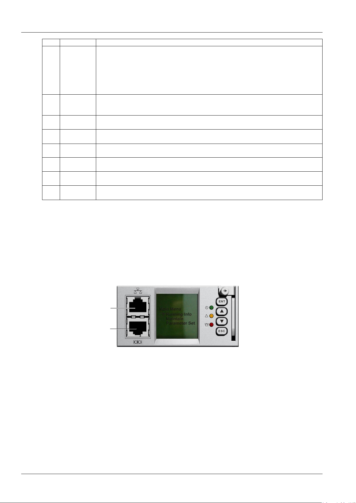
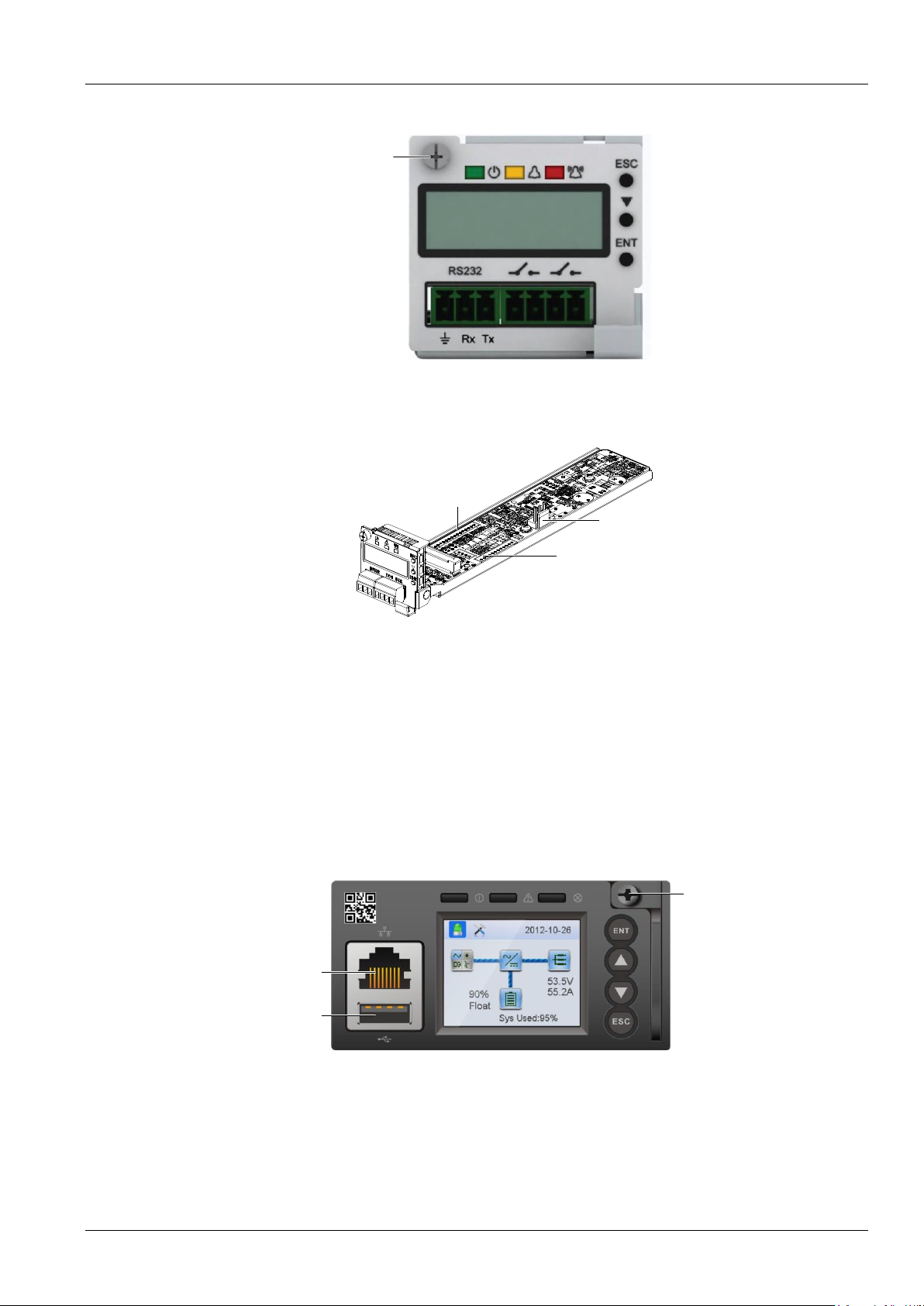
The symptoms of usual controller faults include:power indicator(green) off. LCD doesn't display( if connected to the
host system, it may cause an external alarm). Check whether the system bus voltage is normal. If not, check whether
the terminal of the controller is in normal connection. If both are in normal, the controller is faulty, please see the
following procedures to replace the controller.
M221S/M222S replacement:
1.Check the new controller for damage.
2.Loosen the captive screw of the controller, as shown in Figure 4-1
以太网口
RS232通讯串口
RS232 communication
serial port
Ethernet port
Figure 4-1 M221S/M222S Controller replacement
3.Push the new controller into the system and tighten the captive screw of the controller
4.After controller startup, refer to 3.2 Basic Settings
M225S controller replacement:
1. Security preparation
Put one end of the effective grounding strap at the wrist and the other end attached to a suitable ground.
Page 29
Chapter 4 Troubleshooting 21
NetSure 731 A41 Subrack Power System User Manual
2. Loosen the captive screw of the controller, as shown in Figure 4-2.
Captive screw
Figure 4-2 M225S Controller replacement (1)
3. Pull out the controller unit slowly until the J2 terminal is completely exposed, and pull out the connected terminals
fromJ2,J6,J7 carefully and do insulation respectively.( as shown in Figure 4-3 ).
J6
J2
J7
Figure 4-3 M225S Controller replacement (2)
4. Push the new controller into the system and insert connection terminals to the corresponding J2, J6 and J7
respectively. Make sure that the connections are fastened, then push the controller into the system.
5. Tighten the captive screw of the controller.
6. After controller startup, refer to 3.2 Basic Settings
Replacement of the M830B controller
The procedures for replacing M830B controller are as follows:
1. Check the new controller for damage.
2. Loosen the captive screw of the controller, as shown in Figure 4-4.
USB接口
以太网口
松不脱螺钉
Ethernet port
USB port
Captive screw
Figure 4-4 M221S/M222S Controller replacement
3. Push the new controller into the system and tighten the captive screw of the controller
4. After controller startup, refer to 3.2 Basic Settings
Page 30
22 Chapter 4 Troubleshooting
NetSure 731 A41 Subrack Power System User Manual
4.2 Rectifier Fault Handling
Alarm handling
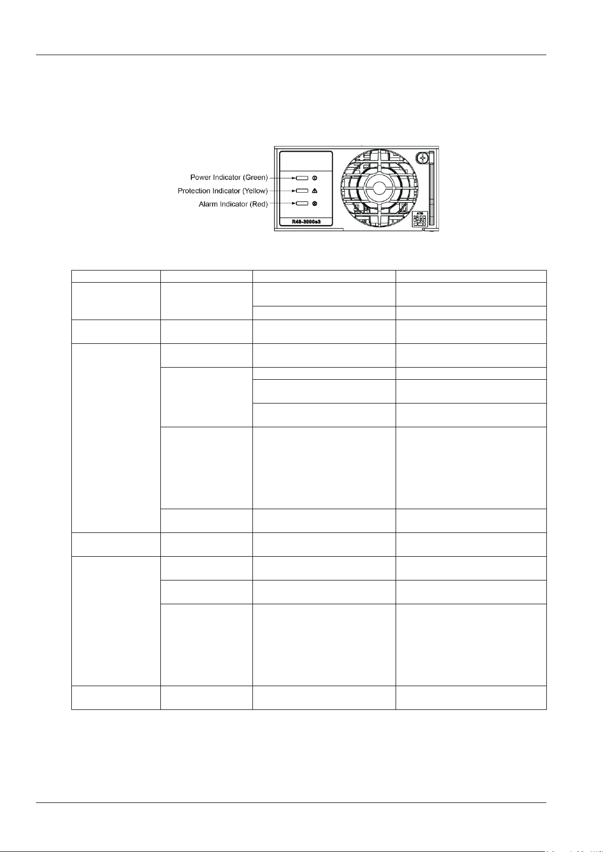
The symptoms of usual rectifier faults include: power indicator ( green ) off, protection indicator ( yellow) on,
protection indicator blink , fault indicator (red) on and fault indicator blink, the indicator locations as shown:
Figure 4-5 Local Indicator Locations
Table 4-2 Rectifier Troubleshooting
Symptom
Related alarm
Possible cause(s)
Suggested action(s)
Power Indicator
(Green) Off
No alarm
1.No input/output voltage.
Make sure that there is input/output
voltage
2.Internal input fuse open.
Replace the rectifier
Power Indicator
(Green) flashing
No alarm
The rectifier is being identified by the
controller
Protection(yellow)
Rect protection
AC input voltage abnormal
Make sure the AC input voltage is
normal
Rect over temperature
1. Fan blocked
1. Remove the object that blocks the fan
2. Ventilation path blocked at the inlet
or vent
2. Remove the object at the inlet or vent
3. Ambient temperature too high or
the inlet too close to a heat source
3. Decrease the ambient temperature or
remove the heat source
Rect protection
Current sharing imbalance
Check whether the rectifier
communication is normal. If not, check
whether the communication cable is in
normal connection. If the
communication is normal while the
protection indicator is on, replace the
rectifier
Rect protection
Power factor compensation internal
under voltage or over voltage
Replace the rectifier
Protection indicator
flash (yellow)
Rect communication fail
Rectifier communication fail
Check whether the communication
cable is in normal connection
Fault indicator on(red)
Rect HVSD
Rectifier over-voltage
Reset the rectifier. If the protection is
triggered again, replace the rectifier
Rect fail
Rectifier module addresses
contradictory.
Replace the rectifier module.
Severe load sharing
imbalance.
positive and negative deviations of
average current ≤ 2.5A
Check whether the rectifier
communication is normal. If not, check
whether the communication cable is in
normal connection. If the
communication is normal while the
protection indicator is on, replace the
rectifie
Fault indicator flash
(red)
Rect Fan Fails
Fan fault
Replace the fan.
R48-3000e3, R48-3000A3, R48-3500e3 Replacement
Rectifier modules can be inserted or removed with power applied (hot swappable).
Page 31

Chapter 4 Troubleshooting 23
NetSure 731 A41 Subrack Power System User Manual
Note:
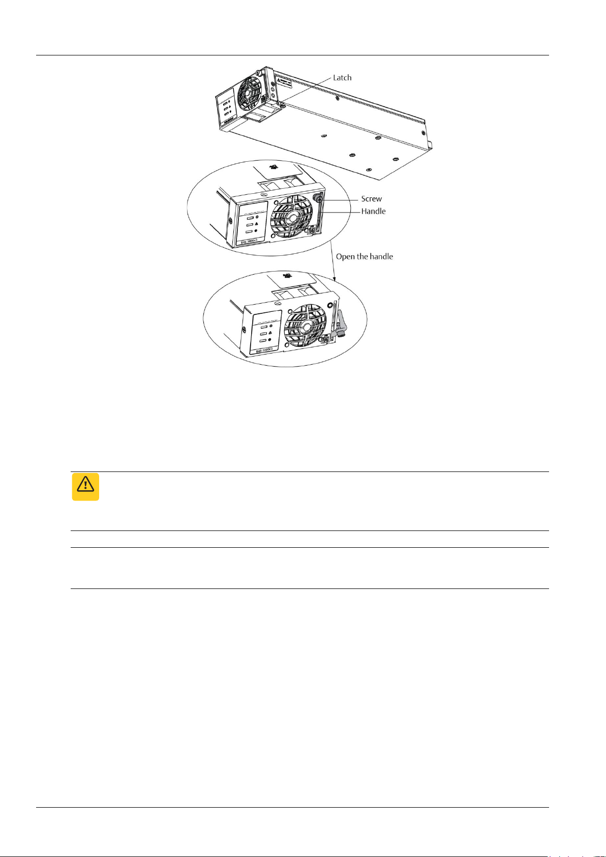
Each rectifier module locks into a module mounting shelf by means of a latch located on the bottom of the module. The latch
and rectifier module handle are interactive. Pushing the handle up into the module’s front panel causes the latch to extend to the
locking position; pulling the handle down out from the module’s front panel causes the latch to retract.
Danger
DANGER!
Take care when removing a rectifier module that was in operation, as rectifier module surfaces could be very hot.
Warning
WARNING!
To prevent damage to the latching mechanism, ensure the handle is in the open position when installing or removing a rectifier
module. NEVER hold the handle in the closed position when installing a rectifier module into a shelf.
Procedure
Refer to Figure 4-6 as this procedure is performed.
1. Performing this procedure may activate external alarms. Do one of the following. If possible, disable these alarms.
If these alarms cannot be easily disabled, notify the appropriate personnel to disregard any alarms associated with
this system while this procedure is performed.
2. Loosen the captive screw on the module’s handle. Pull the handle down out from the module’s front panel (this will
also retract the latch mechanism).
3. Grasp the handle and pull firmly to remove the module from the shelf.
4. Place the replacement rectifier module into the mounting position without sliding it in completely.
5. Loosen the captive screw on the module’s handle. Pull the handle down out from the module’s front panel (this will
also retract the latch mechanism).
6. Push the module completely into the shelf.
7. Push the handle up into the module’s front panel. This will lock the module securely to the shelf. Tighten the
captive screw on the handle.
8. Certain functions (i.e. rectifier current limit, rectifier addressing) may require adjustment when adding or replacing a
rectifier module.
9. After the rectifier modules are physically installed in the mounting shelf(s), they are ready for operation immediately
after power is supplied to them. Verify that the rectifiers are operating normally.
10. Enable the external alarms, or notify appropriate personnel that this procedure is finished.
11. Ensure that there are no local or remote alarms active on the system.
Page 32
24 Chapter 4 Troubleshooting
NetSure 731 A41 Subrack Power System User Manual
Figure 4-6 Installing Rectifier
4.2.2 Rectifier Fan Replacement
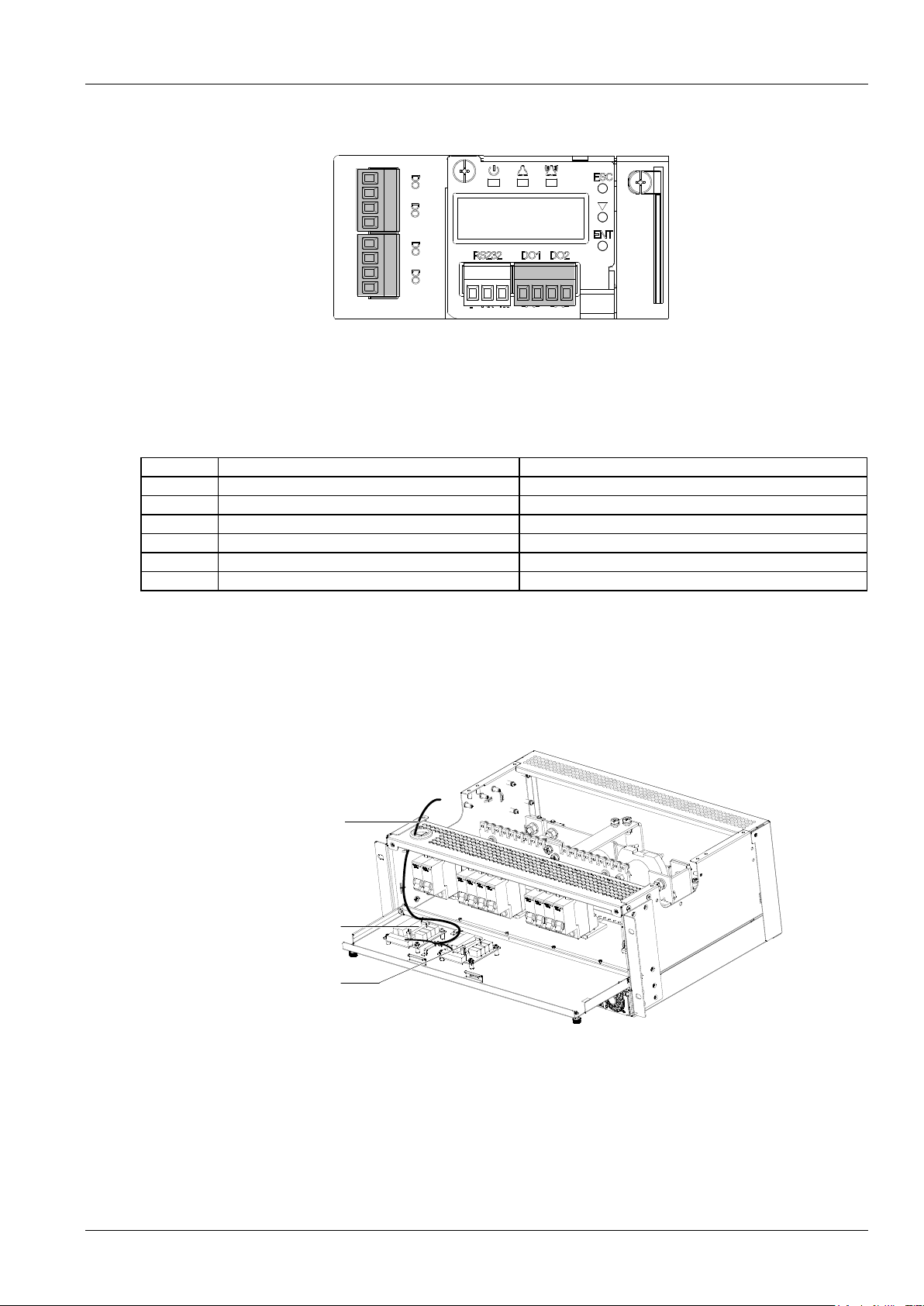
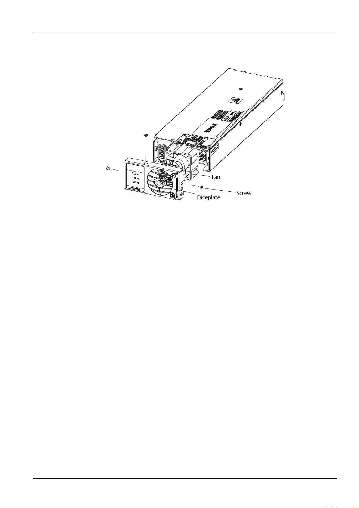
Each Rectifier uses a fan (P/N:32010485) for cooling. If fan replacement should become necessary, perform the
following procedure.
Refer to Figure 4-6 as this procedure is performed.
Warning
WARNING!
In a system with NO redundant Rectifier, battery must have sufficient reserve to power the load(s) while the Rectifier is removed
for fan replacement.
Note:
When performing any step in this procedure that requires removal of existing hardware, retain all hardware for use in subsequent
steps.
Procedure
1. Performing this procedure may activate external alarms. Do one of the following. If possible, disable these alarms.
If these alarms cannot be easily disabled, notify the appropriate personnel to disregard any alarms associated with
this system while this procedure is performed.
2. Remove the Rectifier from the shelf. Refer to a previous procedure for step-by-step instructions.
3. On this Rectifier; remove the front panel by removing the screws securing the front panel to the chassis, and by
unplugging the fan from the printed circuit card.
4. For proper orientation of the new fan, observe the location of the fan wires and the air flow arrows on the old fan.
5. Remove the old fan from the front panel by removing the two screws and clips securing the fan.
6. Install the new fan onto the front panel using the two screws and clips previously removed. Ensure the fan wires
and air flow arrows match the orientation of the old fan.
7. Install the front panel with the new fan onto the chassis by plugging the fan cable into the printed circuit card, and
securing the front panel with the screws previously removed.
Page 33
Chapter 4 Troubleshooting 25
NetSure 731 A41 Subrack Power System User Manual
8. Replace the Rectifier into the shelf. Refer to the previous procedure for step-by-step instructions.
9. Enable the external alarms, or notify appropriate personnel that this procedure is finished.
10.Ensure that there are no local or remote alarms active on the system.
Figure 4-7 Fan replacement
Page 34

26 Appendix 1 Technical And Engineering Data
NetSure 731 A41 Subrack Power System User Manual
Appendix 1 Technical And Engineering Data
Table 1 Technical data
Parameter category
Parameter
Description
Environmental
Operating temperature
-5℃~+40℃(derating is necessary above 40°C)
Storage temperature
-40℃~+70℃
Relative humidity
5%RH~95%RH
Altitude
≤2000m(derating is necessary above 2,000m)
Polution level
Level 2
Others
No conductive dust or erosive gases. No possibility of explosion
AC input
AC input system
L+N+PE/220Vac;
AC input type
TN,TT
Input voltage range
85Vac~300Vac
Input AC voltage
frequency
45Hz~65Hz
Maximum input current
≤74A(including 10A AC output current);
≤84A(using R48-3500e3 modules)
Power factor
≥0.99
Overvoltage level
Level Ⅱ
DC output
Nominal output voltage
-48Vdc
Rated output voltage
-53.5Vdc(If it is used for outdoor,the rated voltage is-54V)
Output DC voltage
-43.2~-57.6Vdc
Maximum output current
DC load output ≤150A (R48-3000e3/R48-3000A3)
DC load output ≤185A (R48-3500e3)
battery charging current≤56A
Note: in 45℃, full load output, above 45℃, the power derating 2% per ℃.
Voltage set-point
accuracy
≤1%
Maximum efficiency
≥94.5%
Noise (peak-peak) (rated
output)
≤200mV(0~20MHz)
Weighted noise (rated
output)
≤2mV(300~3400Hz)
AC input alarm and
protection
AC input over-voltage
alarm point
Default: 280 ± 5Vac, configurable through controller
AC input over-voltage
alarm recovery point
Default: 270 ± 5Vac, 10Vac lower than the AC input over-voltage alarm point
AC input under-voltage
alarm point
Default: 180 ± 5Vac, configurable through controller
AC input under-voltage
alarm recovery point
Default: 190 ± 5Vac, 10Vac higher than the AC input under-voltage alarm point
AC input over-voltage
protection point
305 ± 5Vac by default, configurable through controller
AC input over-voltage
protection recovery point
295 ± 5Vac by default, 10Vac lower than the AC input over-voltage alarm point
AC input under-voltage
protection point
Default: 80 ± 5Vac, configurable through controller
AC input under-voltage
protection recovery point
Default: 95 ± 5Vac, 10Vac higher than the AC input under-voltage alarm point
DC output alarm and
protection
DC output over-voltage
alarm point
Default: -58.0 ± 0.2Vdc, configurable through controller
DC output over-voltage
recovery point
Default: -57.5 ± 0.2Vdc, 0.5Vdc lower than the over-voltage alarm point
DC output under-voltage
Default: -45.0 ± 0.2Vdc, configurable through controller
Page 35
Appendix 1 Technical And Engineering Data 27
NetSure 731 A41 Subrack Power System User Manual
Parameter category
Parameter
Description
alarm point
DC output alarm and
protection
DC output under-voltage
recovery point
Default: -45.5 ± 0.2Vdc, 0.5Vdc higher than the under-voltage alarm point
DC output over-voltage
protection point
Default: -59.0 ± 0.2Vdc, configurable through controller
LLVD
Default: -44.0 ± 0.2Vdc, configurable through controller(If it is used for outdoor,
the default is--46.6±0.2Vdc)
BLVD
Default: -43.2 ± 0.2Vdc, configurable through controller
Rectifier
Current sharing
The rectifiers can work in parallel and share the current. The unbalanceness is
better than ± 5%.
Derate by input (at
45°C)
176Vac input, The rectifier output is 100% power
154Vac~176Vac input,the rectifier output power increased from 2900W to
3000W.
85Vac~154Vacinput,the rectifier output power increased from 1500W to 2900W.
Below 80Vac,the rectifier low pressure power off.
Walk-in
The output voltage can rise slowly when the rectifier start up. The walk in time is
configurable through the controller.
Fan speed adjustable
Rectifier fan speed can be set to auto or full speed.
Over-voltage protection
The rectifier provides over-voltage hardware and software protection. The
hardware protection point is 59.5V ± 0.5V, and it requires manual resetting to
restore operation. The software protection point is between 56V and 59V (0.5V
above output voltage, 59V by default), and can be set through the controller
There are two software protection modes, which can be selected through the
software at the host:
1. Lock out at the first over-voltage
Once the output voltage reaches protection point, the rectifier will shut off and
hold that state. It requires manual resetting to restore the operation
2. Lock out at the second over-voltage
When the output voltage reaches the software protection point, the rectifier will
shutdown, and restart automatically after 5 seconds. If the over-voltage happens
again within a set time (default: 5min. Configurable through controller), the
rectifier will shut off and hold that state. It requires manual resetting to restore
the operation
Manual resetting: Resetting can be done manually through the controller, or by
removing the rectifier from system
Temperature power
limiting
The rectifiercan start in -40℃;
Below 45℃, the rectifier with full power (3000 W) output.
From 45℃~55℃, the rectifier with linearly derating to 2900W.
From 55℃~65℃, the rectifier with linearly derating to 2250W.
From 65℃~70℃, the rectifier with linearly derating to 0W.
EMC
Conducted emission
Class A EN55022
Radiated emission
Harmonic current
emission
Class A EN61000-3-12
Voltage fluctuation and
flash
EN61000-3-11
EFT
Level 4 EN/IEC 61000-4-4
ESD
Level 3 EN/IEC 61000-4-2
Surges
Level 4 EN/IEC 61000-4-5
Radiation
Level 3 EN/IEC 61000-4-3
Conduction
Level 2 EN/IEC61000-4-6
Lightning protection
features
At AC side
The AC input side can withstand five times of simulated lightning voltage of 5Kv
at 10/700µs, for the positive and negative polarities respectively. It can withstand
five times of simulated lightning surge current of 20Ka at 8/20µs, for the positive
and negative polarities respectively. The test interval is not smaller than 1
minute. It can also withstand one event of simulated lightning surge current of
40kA at 8/20µs.
Page 36
28 Appendix 1 Technical And Engineering Data
NetSure 731 A41 Subrack Power System User Manual
Parameter category
Parameter
Description
Others
Safety regulation
Conform to IEC60950-1 standards
Acoustic noise
≤ 60db (A) (When the ambient temperature is lower than25°C )
Insulation resistance
At temperature of 15°C ~ 35°C and relative humidity not bigger than 90%RH,
apply a test voltage of 500Vdc. The insulation resistances between AC circuit
and earth, DC circuit and earth, and AC and DC circuits are all not less than
2MΩ
Insulation strength
(Remove the SPD, controller and rectifiers from the system before the test.)
AC loop to DC loop can withstand 50Hz. AC to DC circuits: 3,000Vac; or
4,242Vdc for one minute, leak curren≤10mA , without puncturing and electric
arcing;
AC circuit to earth: 50Hz, 2,500Vac; or 3,535Vdc for one minute, leak
curren≤10mA , without puncturing and electric arcing ;
DC circuit to earth: 50Hz, 1,000Vac; or 1,414Vdc for one minute, leak
curren≤10mA , without puncturing and electric arcing ;
Auxiliary circuit without connecting to the main circuit directly: 50Hz,500Vac; or
707Vdc for one minute, leak curren≤10mA , without puncturing and electric
arcing ;
MTBF
> 200,000hr
ROHS
Compliant with R5 requirement
Mechanical
Dimensions (mm)
Standard dimensions of the
subracks:
483 mm×390 mm×178 mm
Controller:
M221S\M222S\M830B:87×212×42
M225S:43.6×212×42
Rectifier:
85.1×330×43.6
Weight (kg)
Subrack (package,rectifier
and controller are all
included)
≤25;
Subrack (without
package,rectifier and
controller included)
≤15;
Page 37
Appendix 2 Installation Instruction Of Battery Rack 29
NetSure 731 A41 Subrack Power System User Manual
Appendix 2 Installation Instruction Of Battery Rack
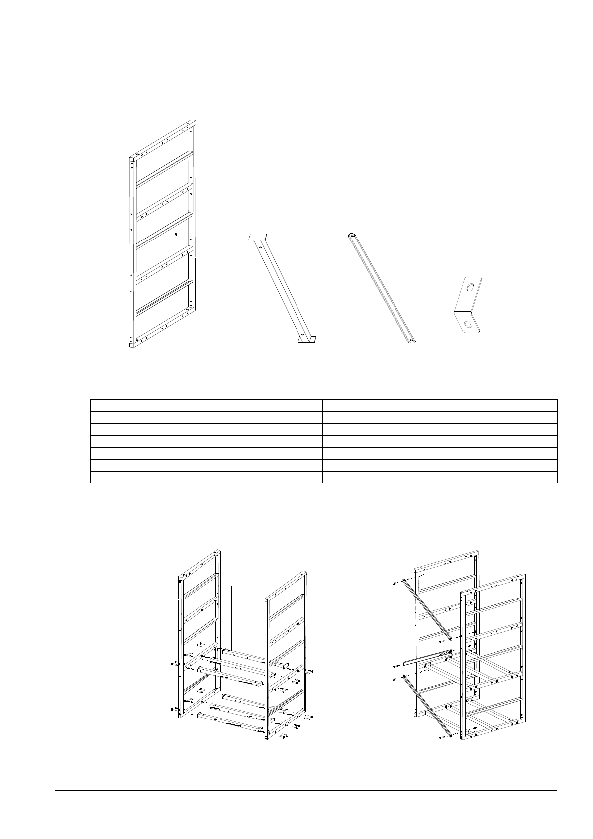
1. Installation Instruction Of Two-Layer And Four-Layer Battery Rack
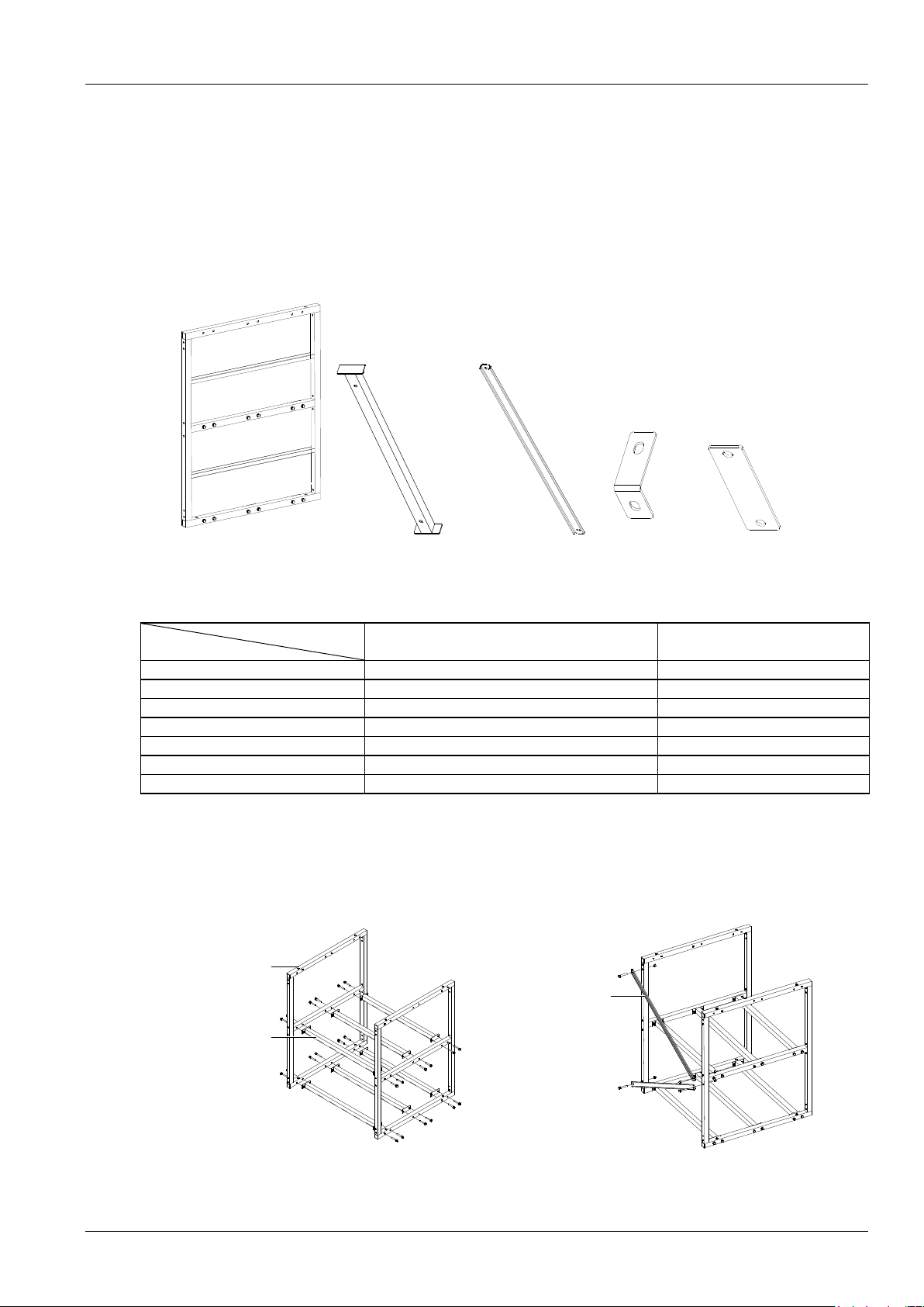
Packing list
Accessory 1 Accessory 2 Accessory 3 Accessory 4 Accessory 5
Figure 1 Accessory
Table 2 Packing list of the battery rack
Battery rack
Accessory
Two-layer battery rack
Four-layer battery rack
Accessory 1
2
4
Accessory 2
8
14
Accessory 3
2
4
Accessory 4
2
2
Accessory 5
0
2
Expansion bolt
4 pieces
4 pieces
Fastener
1 set
1 set
Installation procedures
1. Installation procedures of two-layer battery rack
1) Install accessory 1 and accessory 2 according to Figure 2 (a).
2) Install accessory 3 according to Figure 2 (b).
Accessory 1
Accessory 2
Accessory 3
(a) (b)
Figure 2 Installation procedure of accessory 1 ~ accessory 3
Page 38
30 Appendix 2 Installation Instruction Of Battery Rack
NetSure 731 A41 Subrack Power System User Manual
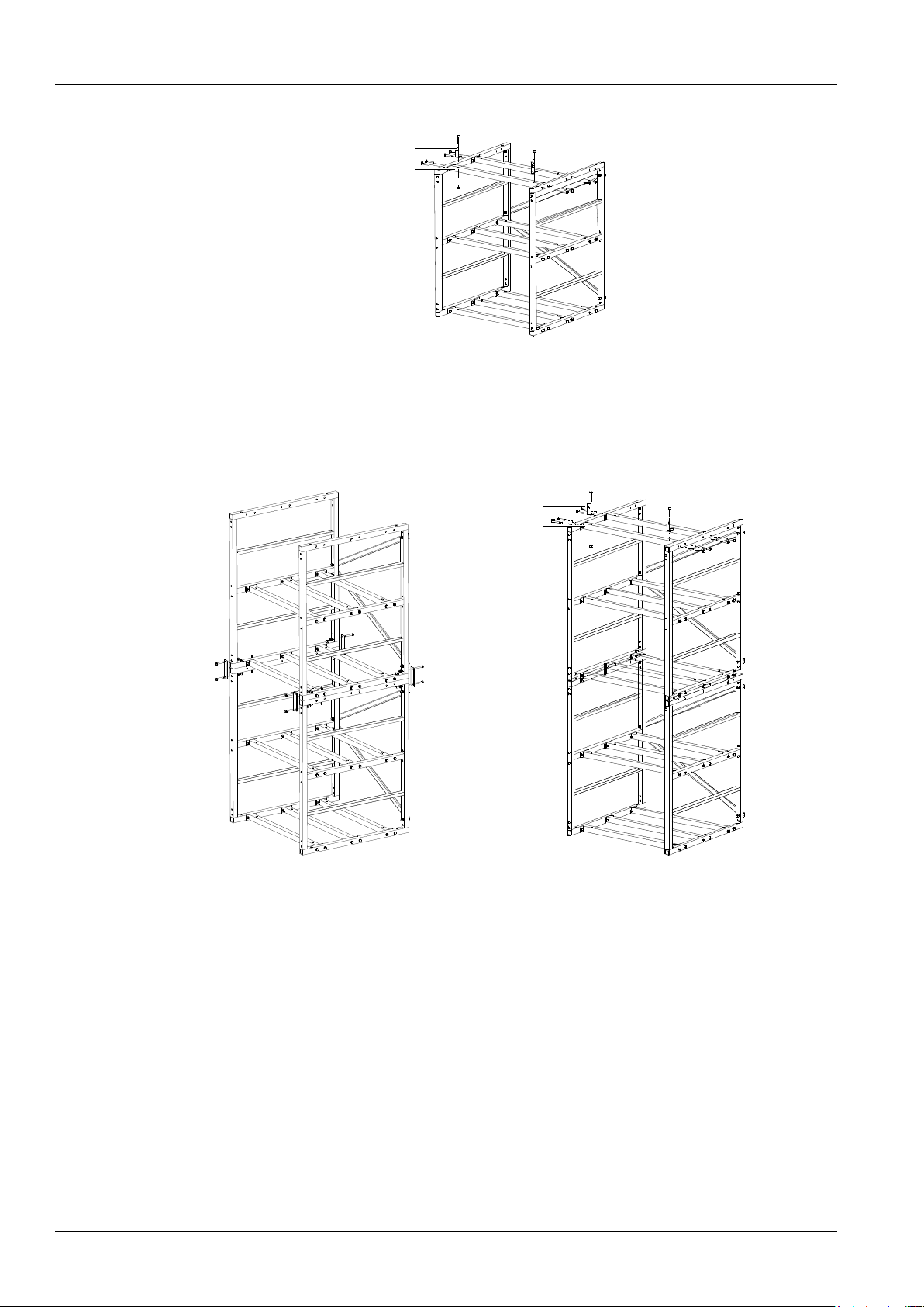
3) Install accessory 2 and accessory 4 according to Figure 3.
Accessory 4
Accessory 2
Figure 3 Installation procedure of accessory 2 and accessory 4
2. Installation procedures of four-layer battery rack
1) Install accessory 1, accessory 2 and accessory 3 according to Figure 2 (a) and Figure 2 (b).
2) Install accessory 5 according to Figure 4 (a).
3) Install accessory 2 and accessory 4 according to Figure 4 (b).
Accessory 4
Accessory 2
(a) (b)
Figure 4 Installation procedure of accessory 2, accessory 4 and accessory 5
Page 39
Appendix 2 Installation Instruction Of Battery Rack 31
NetSure 731 A41 Subrack Power System User Manual
2. Installation Instruction Of Three-Layer Battery Rack
Packing list
Accessory 1 Accessory 2 Accessory 3 Accessory 4
Figure 5 Accessory
Table 3 Packing list of the battery rack
Accessory
Accessory number
Accessory 1
2
Accessory 2
6
Accessory 3
3
Accessory 4
2
Expansion bolt
4 pieces
Fastener
1 set
Installation procedures
1. Install accessory 1 and accessory 2 according to Figure 6 (a).
2. Install accessory 3 according to Figure 6 (b).
Accessory 1
Accessory 2
Accessory 3
(a) (b)
Figure 6 Installation procedure of accessory 1 ~ accessory 3
Page 40
32 Appendix 2 Installation Instruction Of Battery Rack
NetSure 731 A41 Subrack Power System User Manual
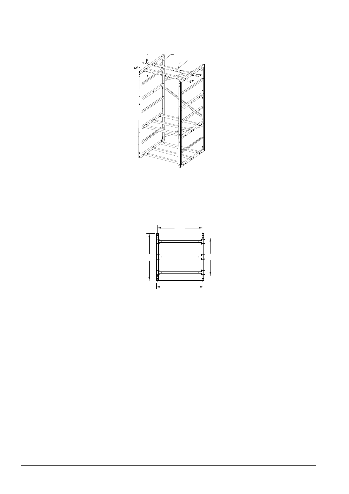
3. Install accessory 2 and accessory 4 according to Figure 7.
Accessory 4
Accessory 2
Figure 7 Installation procedure of accessory 2 and accessory 4
3. Fixing The Battery Rack
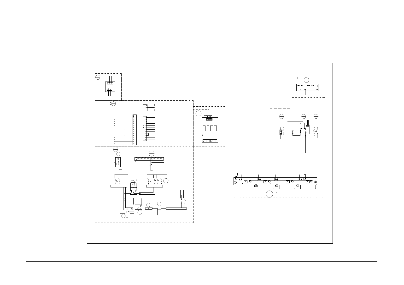
1. Fix the battery rack to the ground according to the installation dimensions shown in Figure 8. The fixing bolts are
accessories.
600
600
575
480
Figure 8 Installation dimensions (unit: mm)
2. Fix the subrack subrack power system onto the top of the battery rack. Refer to2.3 Mechanical Installation
Page 41
Appendix 3 Wiring Diagram 33
NetSure 731 A41 Subrack Power System User Manual
Appendix 3 Wiring Diagram
MFU DC wiring diagram
MFU
8
Rear top view
13
M225S1X1
User interface board 1
monitor motherboard
M225S
7
18
M34C3C1
Subrack
1
3
2
5-2
W07
2 1
1
2
PL
121
2
7-J6-9
QFB1
QFB2
7-J6-10
7-J6-8
7-J6-7
18-J2-1
18-J2-2
W80
1
2
7-J7-11
8-PL-2
NPL
8-B-
121
2
QFD1
QFD2
1
2
QFD3
1
2
QFD8
NPL
121
2
QFD9
QFD12
PL
0V
To the positive busbar of the module
PE
5
1
BUS+
9
RB
10
KM1
11
KM2
12
2
9-2
1
W80
7-J6-11
7-J6-11
W84
W80
W80
W84
W80
7-J7-4/7-J7-12
9-BUS+-2
12--KM2-1
W84
4
2
W80
Single AC input (wi th AC SPD)
Front view
1
2
11-KM1-2
W80
W80
7-J7-1
W80
Right view
H5
DC-
DC-
L N
L N L N
L N
J2
J1
J4J3
H2
H1
J13
J11
H3 H4
DC+
U1 U2DC+DC-J12 U3
DC+
U4
DC+
DC-
J14
U11 U12
U13
U14
DC-
DC+
1-2
2-N-1
1-2
J41
CAN+CAN-
J42
CAN+CAN-
W01
Front top view of the back plat (with the controller and rectifier)
1-2
1-2
W80
8-PL
QFA
1
SPD1
2
L
1 3
2 4
N
L
N-1
PE
COM
NC
NO
W80
7-J7-7
7-J7-8
W01
W01
31-J1-L/31-J2-L/31-J3-L/31-J4-L/3-2
2-N-2
W01
W01
N-2
31-J1-N/31-J2 -N/32-J3-N/32-J 4-N
1-4/3-4
31
W2493ZX1
2
J2
1
2
3
J1
1
7-J7-5
7-J7-6
12-KM2-1
12-KM2-2
8-PL-1
W84
J6
1
2
3
4
5
6
7
8
9
10
11
12
13
14
15
J7
1
2
3
4
5
6
7
8
9
10
11
12
J2
1
2
3
X4-1
CAN-
CAN+
13-J1-1
10-RB-1
10-RB-2
8-QFB1-1
8-QFD
13-J1-5
8-PL-1
9-BUS+-1
18-J1-1
2-COM
2-NC
11-KM1-1
9-BUS+-1
J1
1
8
DO3
DO4
DO5
DO6
J3
J2
W80
W80
13-J1-2
13-J1-3
13-J1-4
13-J1-6
13-J1-7
13-J1-8
W80
8-QFB2-1
W80
18-J2-3
18-J1-2
W84
W80
W80
W80
W80
W80
W80
To subrack PE bar
To SPD PE bar
This diode cintai ns in the W80 cable
1
2
N L
2-L
3
4
W01W01
2-N-2
QFA2
3
W80
7-J6-2
7-J6-1
31-J42-CAN31-J42-CAN+
8-PL-2
J6
J3
15
M2433X2
J7J5
J1 J2 J4
v-
v+
PE
5-4
W06
DCSPD
15-J6
W06
15-J7
W06
8-QFD
W80
door
W80
W80
W80
W01
W01
W01
2-N-1
2-N-1
2-N-1
31-H5
W07
5-4
W07
W06
socket
Top view
Note: Connet X4-1 and the cable of the temperature sensor.
To the negative busbar of the module
Pull out the controller
Figure 9 NetSure 731 A41-S1 wiring diagram
Page 42
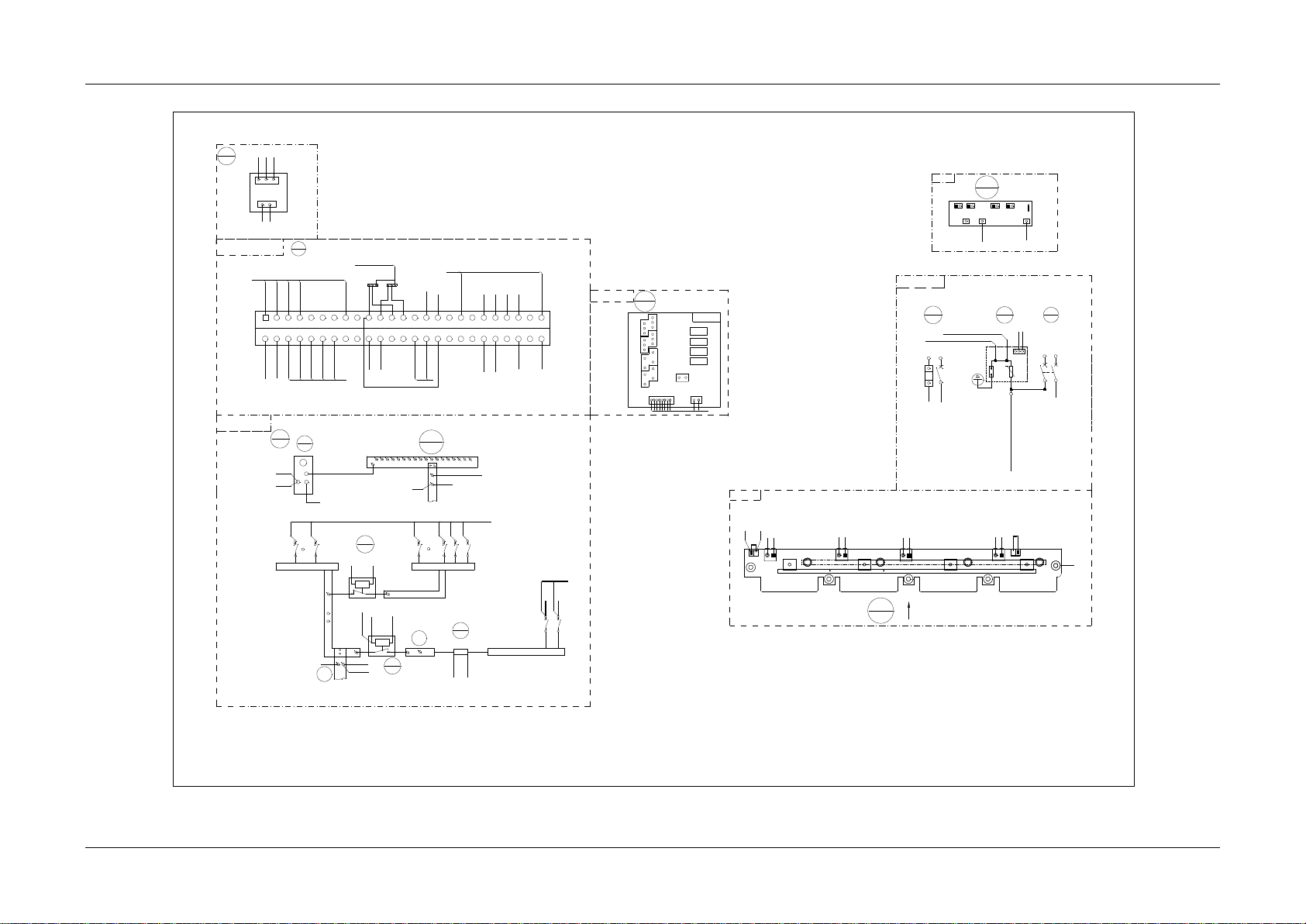
Appendix 3 Wiring Diagram 34
NetSure 731 A41 Subrack Power System User Manual
MFU
8
13
W2453X1
W2453X1
J6
21
J3
1+
1-
2+
2-
LCU+ controller busbar s ocket
J8
1
8
W80
J7
1 2
12345678910111213141516171819202122232425262728293031323334353637383940414243444546474849
50
13-J8-1
31-J42-CAN-
M221S
7
18-J1-1
11-2
11-1
31-J42-CAN+
13-J7-1
13-J7-2
13-J8-2
13-J8-3
13-J8-5
13-J8-4
13-J8-6
13-J8-7
13-J8-8
8-QFB2-1
8-QFB1-1
10-2
10-1
W80
W80
W84
W84
W80
W80
W80
W80
W80
W80
W80
9-BUS+-2
X6-1
X5-1
8-PL-1
W80
9-BUS+-1
W80
W80
8-PL-1
18
M34C3C1
18-J1-2
W80
J4
3+
3-
4+
4-
DO3
DO4
DO1
DO2
1
2
3
5-2
W07
2
1
1
2
PL
121
2
7-30
QFB1
QFB2
7-28
7-20
7-22
18-J2-1
18-J2-2
W80
1
2
7-45
7-43
NPL
8-B-
121
2
QFD1
QFD2
1
2
QFD3
1
2
QFD8
NPL
1
2
1
2
QFD9
QFD12
PL
0V
PE
5
1
BUS+
9
RB
10
KM1
11
KM2
12
2
9-2
1
7-29
W84
W80
W80
W84
W80
W80
7-35/7-49/7-50
9-BUS+-2
12-1
W84
4
2
W80
9-BUS+-1
X5-1
W80
8-QFD
Front view
1
2
15-J7
W80
W06
7-31/7-46
18-J2-3
W84
W80
Front top view (open the panel)
2
J2
1
2
3
J1
1
7-39
7-41
12-1
12-2
8-PL-1
W84
W84
8-PL
QFA
1
SPD1
2
QFA2
3
L1
1
3
2
4
N
L
N-1
PE
1
2
N L
2-L
3
4
W01W01
COM
NC
NO
W80
7-42
7-40
W01
W01
2-N-2
31-J1-L/31-J2-L/31-J3-L/31 -J4-L/3-2
2-N-2
W01
W01
N-2
31-J1-N/31-J2-N/32-J3-N /32-J4-N
3-4/1-4
8-PL-2
W06
J6
J3
15
M2433X2
J7
J5
J1 J2 J4
v-
v+
PE
5-4
W06
DCSPD
15-J6
W06
31-H5
W07
2-NC
2-COM
H5
DC-
DC-
L N
L
N L N
L N
J2
J1
J4
J3
H2
H1
J13
J11
H3 H4
DC+
U1 U2
DC+DC-
J12 U3
DC+
U4
DC+
DC-
J14
U11
U12
U13
U14
DC-
DC+
1-2
2-N-1
1-2
J41
CAN+CAN-
J42
CAN+ CAN-
W01
1-2
1-2
W80
31
W2493ZX1
W80
7-4
7-2
W01
W01
W01
2-N-1
2-N-1
2-N-1
5-4
W07
Front view
MFU DC wiring diagram
Rear top view
To SPD PE bar
To the positive busbar of the module
To the negative busbar of the module
Note: Connet X5-1 to the X6-1 and the cable of the temperature sensor.
User interface board 1
Single-phase AC
input with the SPD
Subrack
Front top view of the back plat (with the controller and rectifier)
Figure 10 NetSure 731 A41-S2 wiring diagram
Page 43
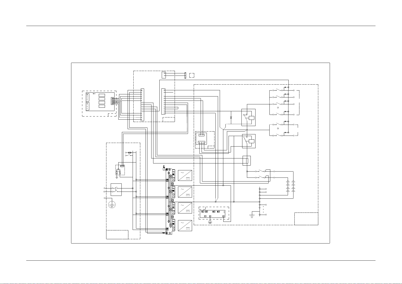
Appendix 4 Schematic Diagram 35
NetSure 731 A41 Subrack Power System User Manual
Appendix 4 Schematic Diagram
Battery 1
Battery 2
QFB2
H4
RS1
QFD12
PL
Class C SPD
H3
H2
H1
KMD1
LLVD Contactor
NPL
KMD2
N
Main input
QFA1
AC Distribtion Unit
L
BLVD Contactor
SPD1
PE
1
2
3
4
L
N
PE
COM
NC
NO
H5
DC-
DC-
L N
L N
L N L N
J2
J1
J4J3
H2
H1
J13
J11
H3 H4
DC+
U1 U2 DC+
DC-J12
U3
DC+
U4
DC+
DCJ14
U11
U12
U13 U14
DC-
DC+
J41
CAN+
CAN-
J42
CAN+
CAN-
2
1
CANCAN+
Controller M225S
Positive Busbar
12
QFB1
12
12
QFD9
12
QFD8
12
QFD3
12
QFD2
12
QFD1
12
2
J2
1
2
3
J1
1
2
1
2
1
1
2
DC+
DC-
TEMP
J6
1
2
3
4
5
6
7
8
9
10
11
12
13
14
15
1
2
3
4
5
6
7
8
9
10
11
12
J7
W34C3C1
1
2
3
J2
X4-1
PD1
PD2
MB
PD3
ST1
OC1+
OC1OC2+
OC2-
BAT1_SH+
BAT1_SHBAT_FUSE1
BAT_FUSE2
LOAD_FUSE
GND
CREALY3
CREALY4
+5V
POWERPOWER-
POWER+
BLVD_CTRL-
BLVD_CTRL+
DI_SPD+
DI_SPDDI_DOOR+
DI_DOORD02M
DO2
M3_AVREF
V_TEMP
M225S1X1
J1
1
8
DO3
DO4
DO5
DO6
J3 J2
D1
QFA2
J6
J3
J7J5
J1 J2 J4
v-
v+
PE
DCSPD
Optional
AC output
Terminal
1
3
1D1
1D2
1D3
1D8
1D9
1D12
DC Distribtion Unit
Figure 11 Schematic diagram of NetSure 731 A41-S1
Page 44
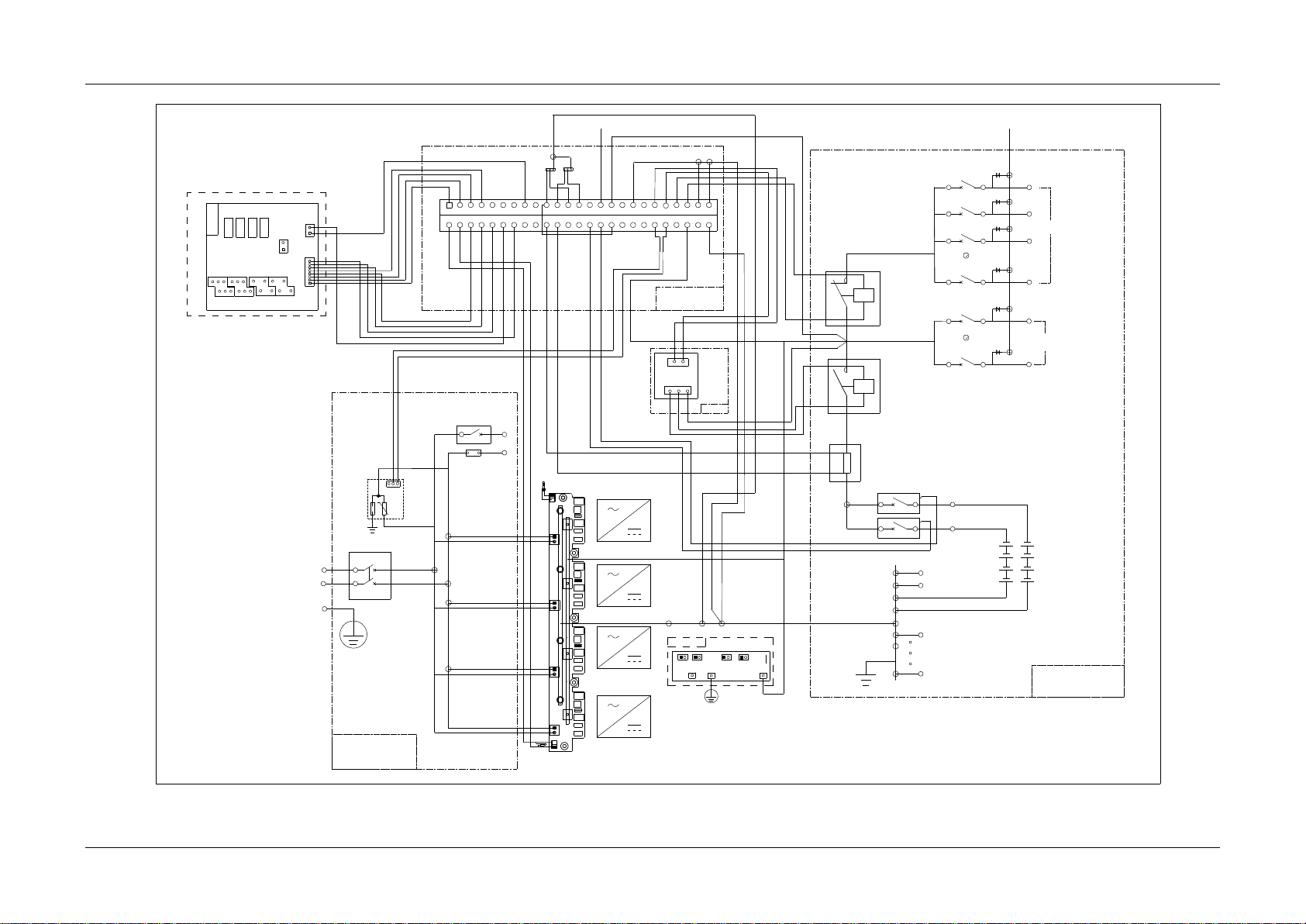
Appendix 4 Schematic Diagram 36
NetSure 731 A41 Subrack Power System User Manual
QFB2
H4
RS1
QFD12
PL
H3
H2
H1
KMD1
NPL
KMD2
N
QFA1
L
N
L
QFA2
SPD1
PE
1
2
3
4
L
N
PE
COM
NC
NO
1
2
Terminal
H5
DC-
DC-
L N
L N
L N
L N
J2
J1
J4
J3
H2
H1
J13
J11
H3
H4
DC+
U1
U2 DC+
DC-J12
U3
DC+
U4
DC+
DCJ14
U11
U12
U13
U14
DC-
DC+
J41
CAN+
CAN-
J42
CAN+
CAN-
2
1
12345678910111213141516171819202122232425262728293031323334353637383940414243444546474849
50
CAN-
CAN+
X5-1
J6
J3
J7
J5
J1 J2 J4
v-
v+
PE
DCSPD
12
QFB1
12
X6-1
W2453X1
J6
21
J3
1+ 1-
2+
2-
J8
1
8
J7
1
2
J4
3+
3-
4+ 4-
DO3
DO4
DO1
DO2
12
QFD9
12
QFD8
12
QFD3
12
QFD2
12
QFD1
12
2
J2
1
2
3
J1
1
2
1
2
1
1
2
DC+
DC-
W34C3C1
PD2
1D1
1D2
1D3
1D8
1D9
1D12
AC output
Class C SPD
Main input
AC Distribtion Unit
DC Distribtion Unit
LLVD Contactor
BLVD Contactor
Battery 1
Battery 2
Positive Busbar
Controller M221S
Figure 12 Schematic diagram of NetSure 731 A41-S2
 Loading...