

Vertiv Tech NetSure 731 A41-S1, NetSure 731 A41-S2, NetSure 731 A41-S8 User Manual

NetSure 731 A41 插框电源系统
用户手册
NetSure 731 A41 Subrack Power
System
User Manual
资料版本 V1.1
归档日期 2017-12-31
BOM 编码 31013139
Version V1.1
Revision date December 31, 2017
BOM 31013139
维谛技术有限公司为客户提供全方位的技术支
持,用户可与就近的维谛技术有限公司办事处
或客户服务中心联系,也可直接与公司总部联
系。
维谛技术有限公司
版权所有,保留一切权利。内容如有改动,恕
不另行通知。
维谛技术有限公司
地址:深圳市南山区学苑大道 1001 号南山智园
B2 栋
邮编:518055
公司网址:www.vertivco.com
客户服务热线:4008876510
E-mail:vertivc.service@vertivco.com
Vertiv Tech provides customers with technical
support. Users may contact the nearest Vertiv
local sales office or service center.
Copyright © 2017 by Vertiv Tech Co., Ltd.
All rights reserved. The contents in this document
are subject to change without notice.
Vertiv Tech Co., Ltd.
Address: Block B2, Nanshan I Park, No.1001
Xueyuan Road, Nanshan District, Shenzhen,
518055, P.R.China
Homepage: www.vertivco.com
E-mail: overseas.support@vertivco.com

Safety Precautions
To reduce the chance of accident, please read the safety precautions very carefully before operation. The
"Caution, Notice, Warning, Danger" in this book do not represent all the safety points to be observed, and are
only supplement to various safety points. Therefore, the installation and operation personnel must be strictly
trained and master the correct operations and all the safety points before actual operation.
When operating Vertiv products, the safety rules in the industry, the general safety points and special safety
instructions specified in this book must be strictly observed.
Electrical Safety
I. Hazardous voltage
Danger
Some components of the power system carry hazardous voltage in operation. Direct contact or indirect contact through
moist objects with these components will result in fatal injury.
Safety rules in the industry must be observed when installing the power system. The installation personnel must
be licensed to operate high voltage and AC power.
In operation, the installation personnel are not allowed to wear conductive objects such as watches, bracelets,
bangles, rings.
When water or moisture is found on the Subrack, turn off the power immediately. In moist environment,
precautions must be taken to keep moisture out of the power system.
"Prohibit" warning label must be attached to the switches and buttons that are not permitted to operate during
installation.
Danger
High voltage operation may cause fire and electric shock. The connection and wiring of AC cables must be in compliance
with the local rules and regulations. Only those who are licensed to operate high voltage and AC power can perform high
voltage operations.
II. Tools
Warning
In high voltage and AC operation, special tools must be used. No common or self-carried tools should be used.
III. Thunderstorm
Danger
Never operate on high voltage, AC, iron tower or mast in the thunderstorm.
In thunderstorms, a strong electromagnetic field will be generated in the air. Therefore the equipment should be
well earthed in time to avoid damage by lightning strikes.
IV. ESD
Notice
The static electricity generated by the human body will damage the static sensitive elements on PCBs, such as large-scale
ICs. Before touching any plug-in board, PCB or IC chip, ESD wrist strap must be worn to prevent body static from
damaging the sensitive components. The other end of the ESD wrist strap must be well earthed.
V. Short circuit
Danger
During operation, never short the positive and negative poles of the DC distribution unit of the system or the non-grounding
pole and the earth. The power system is a constant voltage DC power equipment, short circuit will result in equipment
burning and endanger human safety.
Check carefully the polarity of the cable and connection terminal when performing DC live operations.
As the operation space in the DC distribution unit is very tight, please carefully select the operation space.
Never wear a watch, bracelet, bangle, ring, or other conductive objects during operation.
Insulated tools must be used.
In live operation, keep the arm muscle tense, so that when tool connection is loosened, the free movement of
the human body and tool is reduced to a minimum.
VI. Dangerous energy
Warning
More than 240VA system capacity, keep away from hazardous energy and avoid bridge connection.
Battery
Danger
Before any operation on battery, read carefully the safety precautions for battery transportation and the correct battery
connection method.
Non-standard operation on the battery will cause danger. In operation, precautions should be taken to prevent
battery short circuit and overflow of electrolyte. The overflow of electrolyte will erode the metal objects and PCBs,
thus causing equipment damage and short circuit of PCBs.
Before any operation on battery, pay attention to the following points:
Remove the watch, bracelet, bangle, ring, and other metal objects on the wrist.
Use special insulated tools.
Use eye protection device, and take preventive measures.
Wear rubber gloves and apron to guard against electrolyte overflow.
In battery transportation, the electrode of the battery should always be kept facing upward. Never put the battery
upside down or slanted.
Battery installation requires reliable grounding. And battery is connected before accessing the battery protection
device.
Others
I. Sharp object
Warning
When moving equipment by hand, protective gloves should be worn to avoid injury by sharp object.
II. Cable connection
Notice
Please verify the compliance of the cable and cable label with the actual installation prior to cable connection.
III. Binding the signal lines
Notice
The signal lines should be bound separately from heavy current and high voltage lines, with binding interval of at least
150mm.


Contents
Chapter 1 Overview ............................................................................................................................................................ 1
1.1 Composition and Configuration ............................................................................................................................. 1
Chapter 2 Installation Instruction ......................................................................................................................................... 3
2.1 Safety Regulation .................................................................................................................................................. 3
2.2 Preparation ........................................................................................................................................................... 3
2.3 Mechanical Installation .......................................................................................................................................... 4
2.4 Electrical Installation ............................................................................................................................................. 6
2.4.1 Power System Cabling Method ................................................................................................................. 6
2.4.2 Connecting AC Cables .............................................................................................................................. 7
2.4.3 Connecting Load Cables ........................................................................................................................... 7
2.4.4 Connecting Battery Cables ........................................................................................................................ 8
2.4.5 Connecting Signal Cables ......................................................................................................................... 8
Chapter 3 Commissioning ................................................................................................................................ ................. 15
3.1 Installation Check and Startup ............................................................................................................................ 15
3.2 Basic Settings ..................................................................................................................................................... 16
3.3 Alarm Check And System Operation Status Check ............................................................................................ 17
3.4 Final Steps .......................................................................................................................................................... 18
Chapter 4 Troubleshooting ................................................................................................................................................ 19
4.1 Controller Alarms And Fault Handling ................................................................................................................. 19
4.2 Rectifier Fault Handling ....................................................................................................................................... 22
4.2.2 Rectifier Fan Replacement ...................................................................................................................... 24
Appendix 1 Technical And Engineering Data .................................................................................................................... 26
Appendix 2 Installation Instruction Of Battery Rack .......................................................................................................... 29
1. Installation Instruction Of Two-Layer And Four-Layer Battery Rack ..................................................................... 29
2. Installation Instruction Of Three-Layer Battery Rack ............................................................................................. 31
3. Fixing The Battery Rack ........................................................................................................................................ 32
Appendix 3 Wiring Diagram ............................................................................................................................................... 33
Appendix 4 Schematic Diagram ........................................................................................................................................ 35

Chapter 1 Overview 1
NetSure 731 A41 Subrack Power System User Manual
Chapter 1 Overview
This chapter introduces model composition and configuration and features of NetSure 731A41-S1 and NerSure
731A41-S2 (abbreviated as 'power system' hereinafter).
1.1 Composition and Configuration
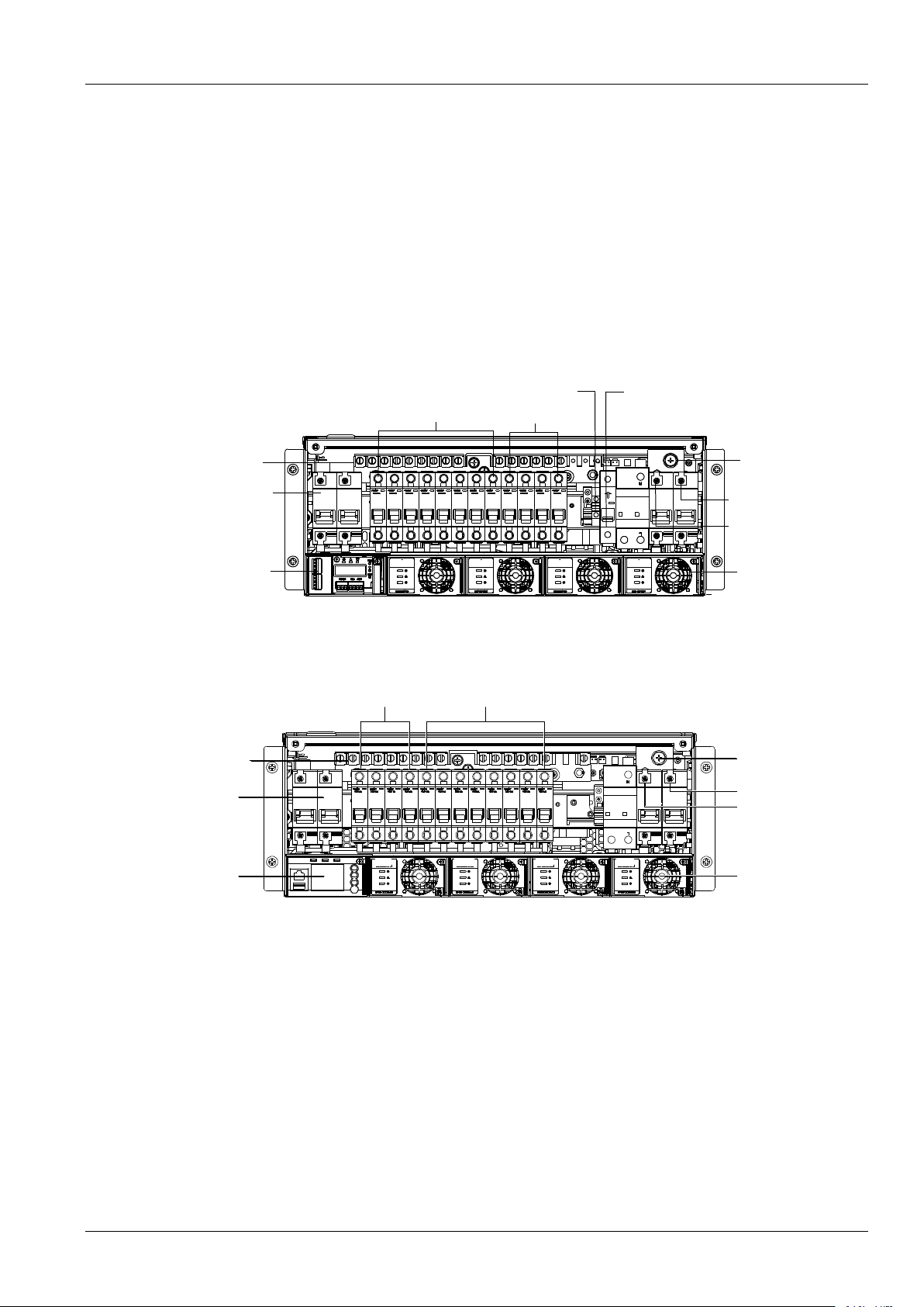
Composition
The power system is composed of power distribution、rectifier modules and controller module.
Take NetSure731A41-S1 for example, the internal structure is shown as Figure 1-1.
Positive terminal
Battery MCB
Controller
Rectifier
AC input terminal N
AC input terminal L
Earthing screw
AC output terminal L
AC output terminal N
Non-prority load
Prority load
Figure 1-1 NetSure 731 A41- S1/S2 system instruction
The internal structure of NetSure731A41-S8 is as shown in Figure 1-3.
监控模块
电池空开
正接线端子
重要负载(PL) 非重要负载(NPL)
接地螺钉
整流模块
交流输入N
交流输入L
Prority load
Non-proity load
Positive terminal
Battery MCB
Controller
Earthing screw
AC input terminal N
AC input terminal L
Rectifier
Figure 1-1 NetSure 731 A41- S8 system instruction

2 Chapter 1 Overview
NetSure 731 A41 Subrack Power System User Manual
Configuration
The configuration of the power system is listed in Table 1-1.
Table 1-1 Configuration of power system
Item
NetSure 731 A41-S1
NetSure 731 A41-S2
NetSure 731 A41-S8
Controller
Model:M225S
Model:M221S/M222S
Model:M830B
Rectifier
Model:
R48-3000e3 or R48-3000A3
Maximum configuration:4 pieces
Model:
R48-3000e3 or R48-3000A3
Maximum configuration:4 pieces
Model:
R48-3000e3 or R48-3000A3 or
R48-3500e3
Maximum configuration:4 pieces
AC power
distribution
L+N+PE/220Vac
L+N+PE/220Vac
L+N+PE/220Vac
DC power
distribution
PL:
32A/1P×2;16A/1P×2 MCB
NPL:
63A/1P×2;32A/1P×4;16A/1P×2
MCB
PL:
32A/1P×2;16A/1P×2 MCB
NPL:
63A/1P×2; 32A/1P×4;16A/1P×2
MCB
PL:
32A/1P×2;16A/1P×2 MCB
NPL:
63A/1P×2; 32A/1P×4;16A/1P×2 MCB
AC output MCB
1×16A/1P
1×16A/1P
NA
Battery MCB
2×125A/1P
2×125A/1P
2×125A/1P
AC SPD
1 piece
1piece
1piece
DC SPD
1piece
1piece
1piece
Cover
Optional
Optional
Optional
BLVD controller
control mode
Controller power-losing mode
Controller power-losing mode
Controller power-losing mode
Main Features
The rectifier uses the active Power Factor Compensation(PFC) technology and the power factor is up to 0.99.
The power system has wide AC input voltage: 85Vac~300Vac.
The rectifier uses soft switching technology, raising the efficiency above 95.5%.
The rectifier has Ultra-low radiation. With advanced EMC design, the rectifier meets international standards such
as CE、NEBS and YD/T983.Both the conducted and radiated interference reach Class B.
The rectifier safety design complies UL,CE and NEBS.
The rectifier is of high power density.
The rectifier is hot pluggable. It takes less than1 min to replace a rectifier.
The rectifier has two optional over-voltage protection methods: hardware protection and software protection. The
latter one also has two optional modes: lock-out at the first over-voltage and lock-out at the second
over-voltage.
The controller module has perfect battery management. The management functions includes BLVD,
temperature compensation, auto voltage regulation , stepless current limiting ,battery capacity calculation and
on-line battery test, etc.
History alarm records:M221S/M222S controller supports 200 history alarms and 1000 history data records,
M225S controller supports 200 history alarms and 512 history data records. And M820B/M830B supports
historical alarm record up to 3000 pcs and historical record up to 60000 pcs.
Battery test data: can record up to 10 sets of battery test data.
The power system is of network design. Providing multiple communication ports (such as RS232, modem and
dry contacts), which enables flexible networking and remote monitoring.
The power system has perfect lighting protection at both AC side and DC side.
The power system has complete fault protection and fault alarm functions.
The power system uses " controller power-losing " control mode . In the indoor or outdoor equipment room
without guard and maintenance, the " controller power- losing mode" can protect the battery from deep
discharge.

Chapter 2 Installation Instruction 3
NetSure 731 A41 Subrack Power System User Manual
Chapter 2 Installation Instruction
2.1 Safety Regulation
Certain components in this power system carry hazardous voltage and current. Always following the instructions
below:
1.Only the adequately trained personnel with satisfactory knowledge of the power system can carry out the
installation. The most recent revision of these safety rules and local safety rules in force shall be adhered to during
the installation.
2.All external circuits that are below 48V and connected to the power system must comply with the requirements of
SELV as defined in IEC 60950.
3.Make sure that the power (mains and battery) to the system is cut off before any operations can be carried out
within the system cabinet.
4.The power cabinets shall be kept locked and placed in a locked room. The key keeper should be the one
responsible for the power system.
5.The wiring of the power distribution cables should be arranged carefully so that the cables are kept away from the
maintenance personnel.
2.2 Preparation
Unpacking inspection
The equipment should be unpacked and inspected after it arrives at the installation site. The inspection shall be done
by representatives of both the user and Vertiv Tech Co., Ltd.
To inspect the equipment, you should open the packing case, take out the packing list and check against the packing
list that the equipment is correct and complete. Make sure that the equipment is delivered intact.
Cables
The cable should be selected in accordance with relevant industry standards.
It is recommended to use the RVVZ cables as AC cables. The cable should reach at least +70°C temperature
durability. With cable length shorter than 30 meters, the Cross-Sectional Area (CSA) calculation should be based on
the current density of 3.5A/mm2. The suggested CSA value is no less than the Table 2-1.
Table 2-1 AC cable CSA selection
AC MCB rated current
Max. AC input current
Min cable CSA
Max cable CSA
125A
74A
25mm2
50mm2
The CSA of DC cable depends on the current flowing through the cable and the allowable voltage drop. To select the
battery cable CSA, see Table 2-2,select the DC load cable CSA according to the Table 2-3.
Table 2-2 Battery cable CSA selection
Battery MCB rated current
Max. battery current
Min cable CSA
Max cable length( volt drop:
0.5V with max. CSA)
125A
105A
35mm2
6m
Note:
1. The specs are applicable at ambient temperature of 25°C.
2. The battery cable should reach at least +90°C heat durability. It is recommended to use double-insulated copper-core flame
retardant cable as battery cable.
4 Chapter 2 Installation Instruction
NetSure 731 A41 Subrack Power System User Manual
Table 2-3 DC load cable CSA selection
Load route
rated current
Max. output
current
Min. cable
CSA
Max cable length ( volt drop: 0.5V
with min. CSA)
Max. cable
CSA
Max cable length ( volt drop: 0.5V
with max. CSA)
63A
50A
16mm2
9m
25mm2
14m
32A
25A
10mm2
11m
25mm2
29m
16A
12A
6 mm2
14m
25mm2
48m
Note: The specs are applicable at ambient temperature of 25°C. If the temperature is higher than this, the CSA of the cable should
be increased.
To prevent the air switching capacity is too large, the load doesn't work when overload. Recommended the capacity
of the air switching is up to 1.5~2 times of the load peak.
The CSA of the system grounding cables should be consistent with the largest power distribution cables. The CSA
value is no less than 25mm2.
AC distribution、DC distribution interface definition see Table 2-4.
Table 2-4 AC distribution、DC distribution interface definition
Connector name
Connector specifications
Wiring instruction
AC power
distribution
AC input MCB
H type terminal, max. cable CSA 50mm2
AC power line
Grounding busbar
One M8 bolt, OT type wiring terminal, max. cable CSA 35mm2
Connected to the
grounding bar of the
building
DC power
distribution
Battery output MCB
H type terminal, max. cable CSA 50mm2
Connected to the
battery port
Negative output MCB
H type terminal, max. cable CSA 25mm2
Connected to the users
negative load port
Positive busbar
Terminal subrack terminal:cable CSA ≤ 50mm2
Connected to the users
positive load port
2.3 Mechanical Installation
Note
1. The cabinet or rack that installed in the subrack must provide fireproof and electric protection casing, or install in cement or
other difficult to burn, at the same time keep enough distance to other combustible material.
2. For the convenience of maintenance, users should maintain a clearance of 800mm at the front of the power system.
3. Subrack cannot be installed against the wall, it must leave enough space for heat dissipation.
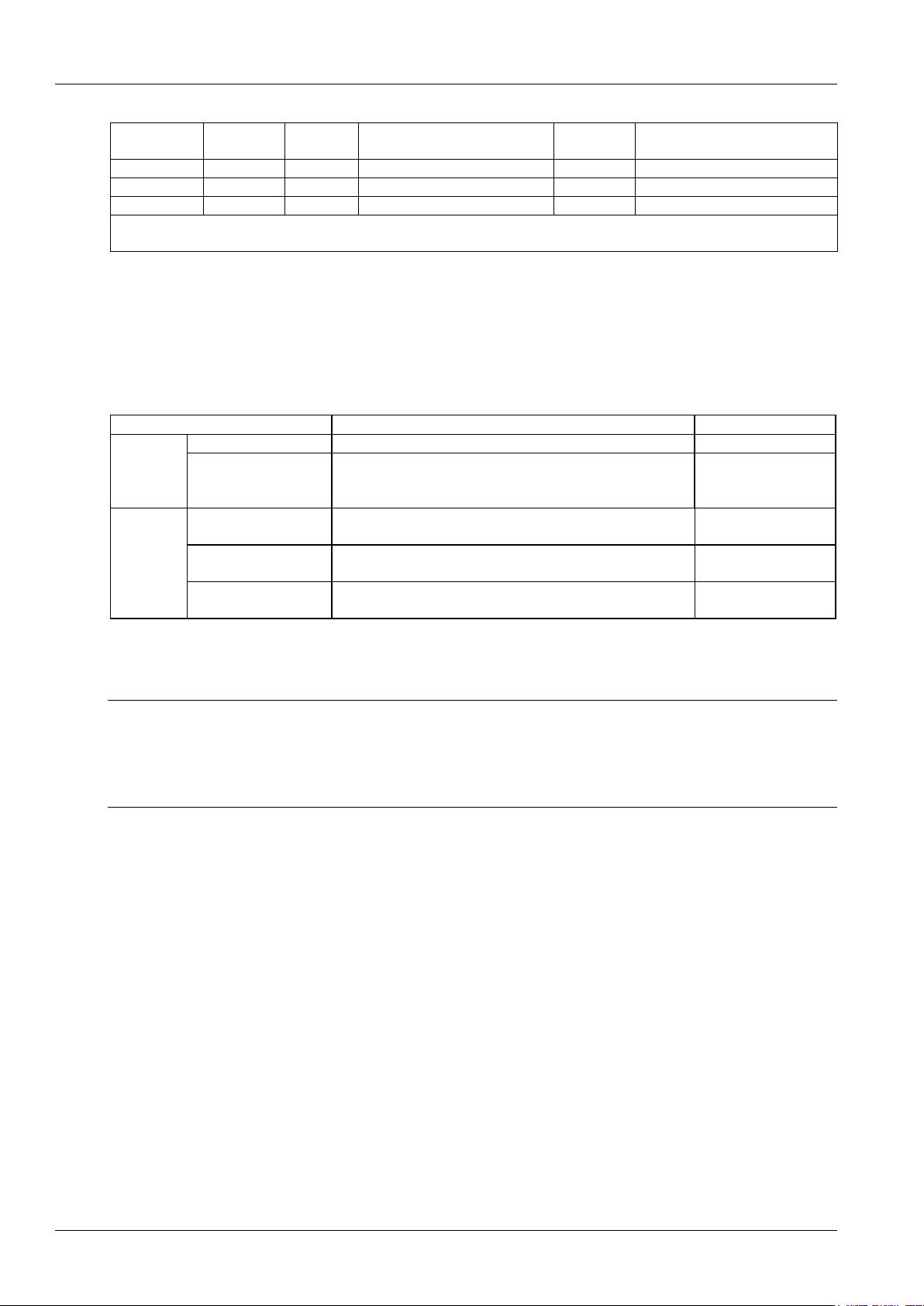
Installed on the battery rack
Fix the subrack power system to the battery rack through the connectors with M6 bolts, as show in Figure 2-1.
Chapter 2 Installation Instruction 5
NetSure 731 A41 Subrack Power System User Manual
Connector
M6 screw
Subrack
power system
Connector
M6 screw
Battery bracket
Battery rack
Power system
Figure 2-1 Cabinet and rack installation
Installed in cabinet
Insert the subrack power system to the matching cabinet, as shown in Figure 2-2.
电源插框
Power subrack
Figure 2-2 Installed in the cabinet system
The engineering graphics of the subrack power system as shown in Figure 2-3.
101.6
177.0
37.7
465.1
482.6
7.0
R3.5
10.0
Figure 2-3 Installation size of NetSure 731 A41(unit::mm)
6 Chapter 2 Installation Instruction
NetSure 731 A41 Subrack Power System User Manual
Note
1. Tighten the captive screw of the MFU Panel by the cross head screwdriver when there is no operation.
2. Also tighten the handle by the cross head screwdriver.
3. Please plug in the new modules or installing a new panel after removing the rectifier module.
2.4 Electrical Installation
2.4.1 Power System Cabling Method
Cabling from the top of the power system
Epoxy board top cover and rubber ring top cover are optional for this system.
Note
If the user requires the system to meet the CE certification, install the epoxy board top cover to be installed at a distance of 1.8
meters high above the ground.
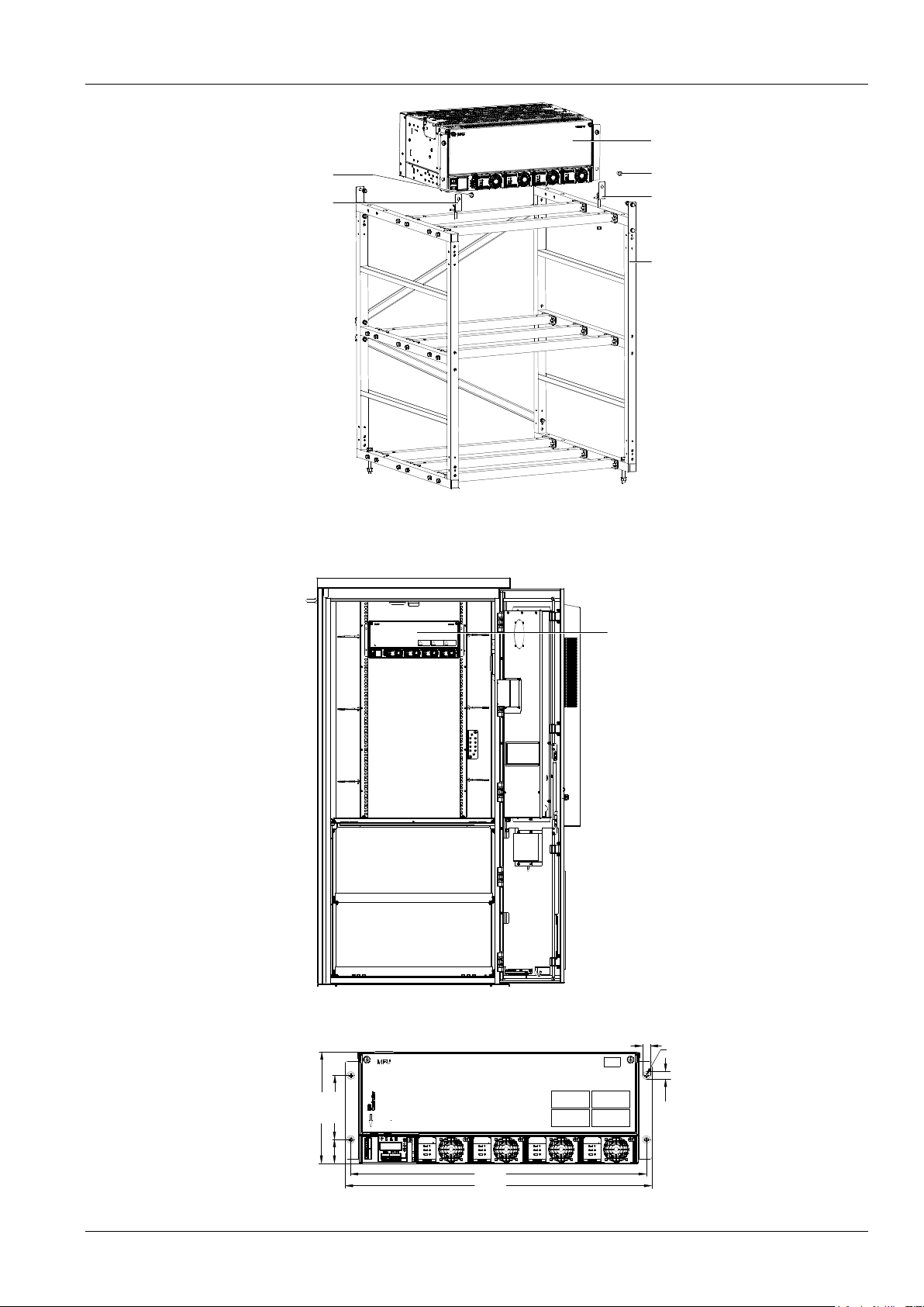
Epoxy board top cover for MFU unit cabling. As shown in the Figure 2-4.
Cable outlet area
Cable-bundling plate
Signal cable
outlet holes
Cable outlet area
Square unit
Figure 2-4 Cable entry illustration of the MFU unit
Rubber ring top cover for MFU unit cabling as shown in Figure 2-5.
Cable outlet area
Latex unit
Figure 2-5 Cable entry illustration of the MFU unit
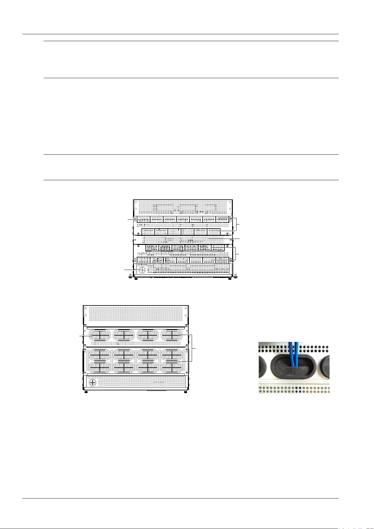
Cabling from side of the power system
Use a cross head screwdriver to remove two screws which fix the cabling panel at side of cabling area, then the cable
can be led out from the cabling area, as shown in Figure 2-6.
 Loading...