

Vertiv Tech NetSure 2100 A31-S1 Installation And Commissioning Manual
Parameter
category
Parameter
Description
AC input
System Input
TN or TT, single-phase (L+N+PE)
Rated input line voltage
220Vac
Input phase voltage range
85Vac ~ 300Vac (output derating
below 176Vac)
Input frequency range
45Hz~65Hz
Rated input frequency
50Hz
Maximum input current
12.3A
DC output
Default output DC voltage
-53.5Vdc
Standard configuration
output current
0 ~ 34.4A
Mechanical
Dimension(W × D × H)
43.6mm × 482mm × 240mm
Subrack power system
weight(kg)
≤ 4kg (excluding rectifiers)
Rectifier weight (kg)
≤ 0.6kg
Environmental
Operating temperature
-5°C ~ +40°C
Relative humidity
≤ 90%RH (30°C)
Altitude
≤2000m (derating is necessary
above 2000m)
Over-voltage/pollution
degree
Over-voltage: II; Pollution degree:2
Load route rated
current
Max. output
current
Min. cable CSA
Max cable length ( volt drop:
0.5V with min. CSA)
30A
20A
4mm2
2.5m
20A
10A
1.5mm2
1.9m
10A
5A
1.5mm2
3.8m
Load route rated
current
Max. output
current
Min. cable CSA
Max cable length ( volt drop:
0.5V with min. CSA)
Note: The specs are applicable at ambient temperature of 25°C. If the temperature
is higher than this, the CSA of the cable should be increased. The maximal cable
CSA should not larger than 10mm2
32
20
Wall
465
Expansion pipe M6 65
×
Flat washer Ф6, spring washerФ6, nut M6 (4 group)
Danger
Danger
NetSure 2100 A31-S1 Subrack Power
System Installation And
Commissioning Manual
1 Technical Parameters
See Table 1-1 for the technical data of NetSure 2100 A31-S1 subrack power system
(power system for short).
Table 1-1 Technical data
The CSA of DC cable depends on the current flowing through the cable, the
allowable voltage drop and the load peak capacity. The recommended load peak
capacity is 1/2 to 2/3 of the MCB/fuse capacity.
The CSA of grounding cable should not less than 2.5mm2, and yellow-green double
color cable is recommended.
2.3 Installing Power System
The power system can be installed against the wall or installed into 19 inch rack.
Note
1. When installing the power system against the wall, make sure that the wall strength and
thickness meet the load-bearing and expansion bolt installation requirements.
2. The three brackets are fixed on both sides of the subrack power system before delivery.
1. If wall-mounting installation is used, firstly remove the three brackets, turn the
bracket with the grounding screw to make the grounding screw facing forward, and
then fasten the bracket to the front of the subrack left side wall, meanwhile,
respectively fix the other two brackets after rotation to the middle of the subrack left
and right side wall. The position of the bracket is shown in Figure 2-2.
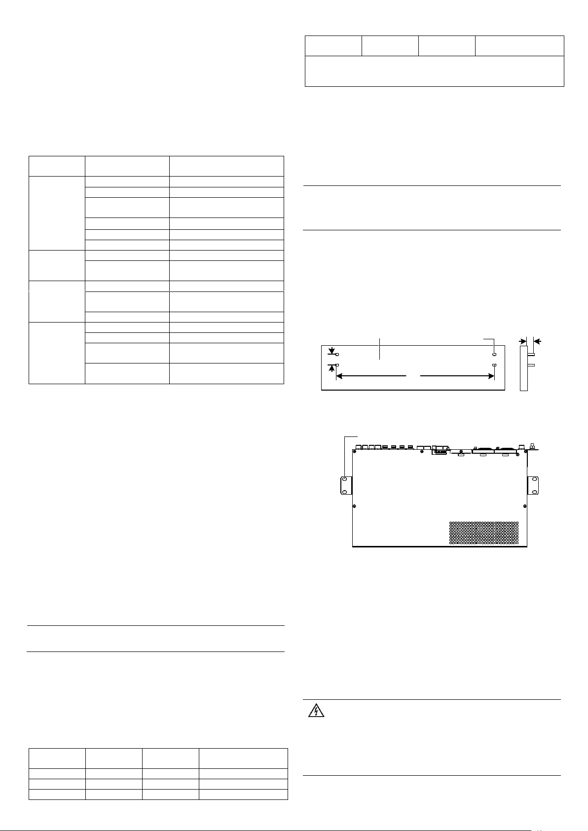
2. By referring to the dimension shown in Figure 2-1, mark the central points of the
installation holes on the floor. Use an electric drill (aiguille: Φ8) to dig holes (depth:
45mm) at the marked points. Clean the holes off dust. Put the four expansion pipes
(M6 × 65) into the holes and keep 20mm exposed.
2 Installation
2.1 Safety Regulations
1. Only the adequately trained personnel with satisfactory knowledge of the power
system can carry out the installation and maintenance.
2. Prevent fire disaster and personnel injury.
3. Provide AC power supply that meets the requirement to equipment.
4. Make sure the equipment is well grounding.
5. Keep the equipment clean and dry.
6. Avoid of touching the bare parts of the circuit.
7. In case of suspicious failure, only can carry out 'Off' operation, shall not carry out
'On' operation.
8. It is strictly forbidden to stand or place objects on the equipment body and
accessories.
2.2 Preparation
Unpacking inspection
To inspect the equipment, you should open the packing case, take out the packing
list and check against the packing list that the equipment is correct and complete.
Make sure that the equipment is delivered intact.
Note
The rectifiers were installed in the subrack power system before delivery.
Cables
The AC cable CSA should take into account the requirements like temperature rise,
voltage drop, mechanical strength and the cable design should meet relevant
industry standards. With cable length shorter than 30 meters, the CSA calculation
should be based on the current density of 2.5A/mm2. The suggested CSA value is
no less than 10mm2.
Select the DC load cable CSA according to the Table 2-1.
Table 2-1 DC load cable CSA selection
Figure 2-1 Installation dimension of cabinet base
3. As shown in Figure 2-2, use four groups of flat washer Ф6, spring washer Ф6 and
nut M6 to fix the power system on the wall.
Figure 2-2 Fixing the power system
4. After the installation, the cabinet should stand firmly no matter how it is shaken.
5. If rack mounting installation is used, firstly remove the three brackets, turn the
bracket with the grounding screw to make the grounding screw facing forward, and
then fasten the bracket to the front of the subrack left side wall, meanwhile, fix any
one of the other two brackets after rotation to the front of the subrack right side wall
(the rest bracket is no need to be fixed). The position of the bracket is shown in
Figure 2-2, use the fixing screws to fasten the subrack power system to the rack
through bracket.
2.4 Cable Connection
All the cables entering or outgoing the power system must be put into the metal pipe
for protection. The metal pipe should be connected to the PE bar reliably. Plastic
coated metal hoses are recommended.
1. Switch off all MCBs before the electrical connection.
2. Only the qualified personnel can do the mains cable connection.
3. Before electrical connection, make sure all the AC MCBs of the power system are
switched off, the AC 230/400V 20A double pole C type MCB is recommended.
4. There is a dangerous voltage in the primary circuit, disconnect the power supply before
maintenance.
1
AC input terminal L
AC input terminal N
Grounding terminal
Load output route 1-
Battery-
Battery+
Load output route 2Load output route 3-
Load output route 3+
Load output route 2+
Load output route 1+
RS232 port
DB9 port
1 (Tx)
2
2 (Rx)
3
3 (GND)
5
No.
Check content
1
Check that the power system is horizontally, vertically and steadily fixed
2
Check that all the bolts are tightened, especially those in electrical
connections. Check that the bolts have plain washers and spring
washers and are not reversed
3
Check that there are no unwanted materials inside the cabinet and clear
up the unwanted materials
4
Check that the power system is intact. If there are scratches, paint them
immediately with antirust paint to prevent corrosion
5
Check the correctness of all MCBs and cables specifications
6
Check the correctness of input and output cable connection, and
communication between the power system and the system grounding.
Make sure that all the cable connections are firm and reliable and the
cable binding is tidy and normative
7
Check the correctness of the battery strings polarities
8
Measure the resistance value between the positive terminal and
negative terminal and phase- to - phase resistance value in the AC loop.
Make sure that there is no short-circuit
9
Check the AC input and distribution. Check that the color of the AC
cables is normative, the cables are laid stably, and the safety labels are
complete
10
Check that the rectifiers are clipped tightly
11
Check that all the MCBs are switched off
Check item
OK
Remark
Make sure that all the MCBs are switched off.
Measure the AC input voltage. Make sure the input voltage
is within the allowable range.
Umin= V
Make sure that the communication and dry contact alarm
output cable are connected to the monitoring board
Make sure that the temperature sensor is installed correctly
Use a voltmeter to measure the battery string voltage and
make sure the battery polarities are correct
Umin= V
Check with an ohmmeter that there is no short circuit
between the positive & negative terminal of DC output,
between the positive & negative battery poles or AC input
terminals (Note: Pull out all modules before the check and
restore them after the check)
Check item
OK
Remark
Switch on the system AC output MCB, the green LED on the
rectifier will be on after a certain delay
Switch on the load MCB. Use a multimeter to check the
voltage of both ends of load, if it shows 53.5V ± 0.5V, the
voltage is normal
Switch on the battery MCB
2.4.1 Connecting Earth Cable
Connect one end of the earth cable to the grounding terminal (see Figure 2-3), and
solder the other end to the grounding metal base outside the power system.
2.4.2 Connecting AC Input Cables
1. The routing method of the AC input cables is the same as that of the earth cables.
Connect the live line (L) and neutral line (N) of the AC input cables respectively to
the lower terminals of the power system AC input terminal L and AC input terminal N,
as shown in Figure 2-3.
Figure 2-3 Illutration of connection terminal
2.4.3 Connecting DC Cables
The power system can be connected with three route of loads respectively
controlled by three MCBs, as shown in Figure 2-3. Connect the negative load cable
to the corresponding load '-' and then connect the positive load cable to the
corresponding load '+' (see Figure 2-3).
2.4.4 Connecting Battery Cable
The power system can be accessed in one group of batteries controlled by a battery
MCB, as shown in Figure 2-3. During connection, connect the negative battery
cable to the battery terminal '-' and then connect the positive battery cable to the
battery terminal '+' (see Figure 2-3).
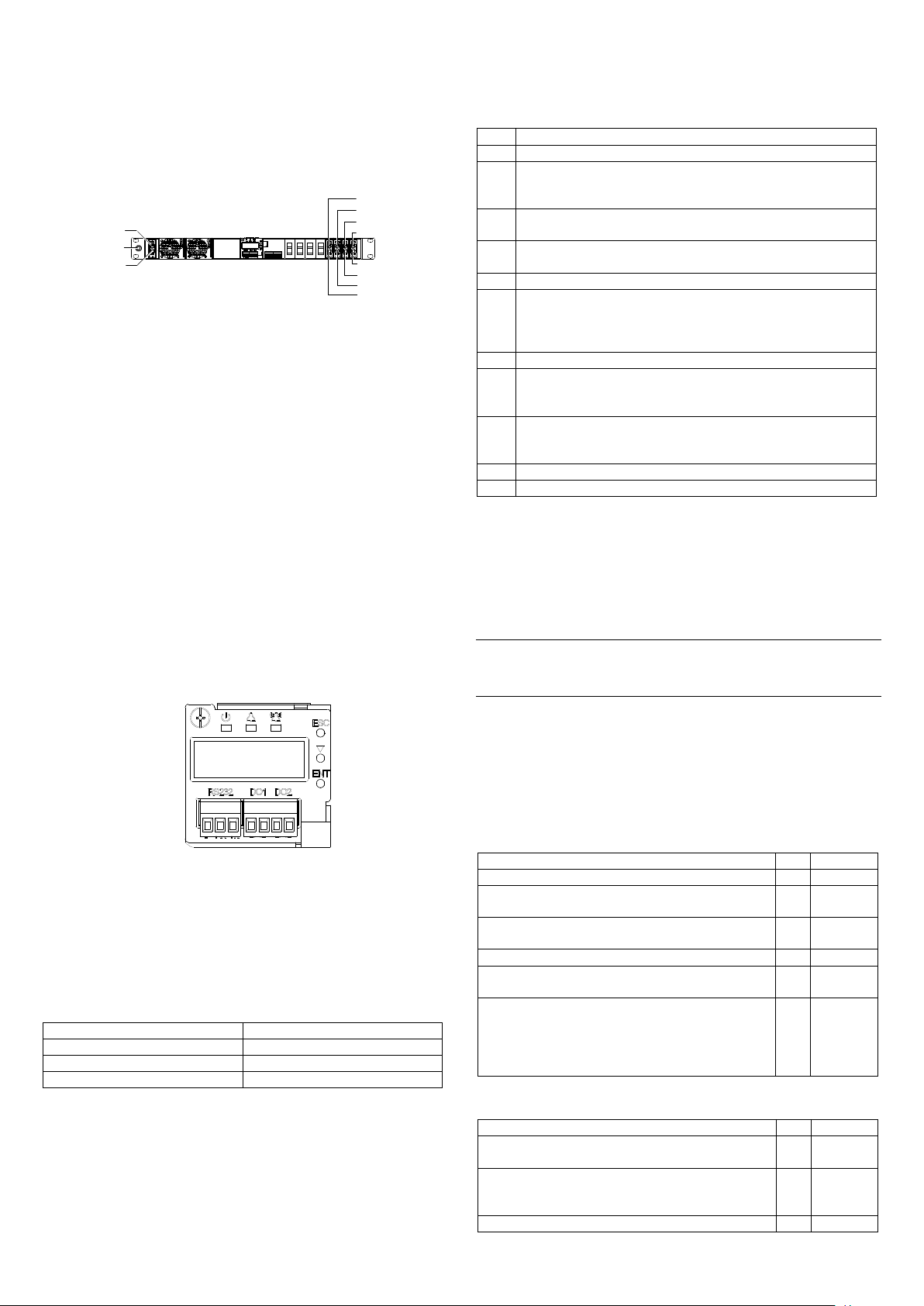
2.4.5 Connecting Communication Cable
Connecting dry contact output port
The controller is configured with two pairs of alarm dry contact output (DO1 ~ DO2)
as standard configuration and four expanded outputs (DO3 ~ DO6) as optional. The
dry contact that generating corresponding alarm is normally closed, users can
connect according to actual needs. When wiring, take out the female of the 4-pin
phoenix terminal bound at the controller handle, connect the multi-core
communication cable with the pipe terminal to the corresponding female of the
phoenix terminal according to the dry contact silkprint on the controller, and then
insert the terminal into the controller front panel. The position of communication
terminal and port definition are shown in Figure 2-4 (Users need to prepare signal
cable themselves).
Figure 2-4 Illutration of controller front panel
Connecting RS232 port
The RS232 port is used for communication with the host. The correlation of the
RS232 and DB9 port on the host is shown in Table 2-2. When wiring, take out the
female of the 3-pin phoenix terminal bound at the controller handle, connect the
multi-core communication cable with the pipe terminal to the corresponding female
of the phoenix terminal according to the RS232 port silkprint on the controller, and
then insert the terminal into the controller front panel, as shown in Figure 2-4 (Users
need to prepare signal cable themselves).
Table 2-2 Correlation of ports
2.5 Installation Check
After the installation, you should carry out the inspection procedures given in
Table 2-3.
Table 2-3 Installation check list
3 Testing
During testing, the corresponding safety regulations must be observed, and the
testing procedures should be followed strictly. The system has been tested before
delivery, the user does not need to carry on the field testing.
3.1 Testing Distribution Unit And Rectifiers
Note
Before the test, inform the chief manufacturer representative. Only trained electrical
engineer can maintain and operate this equipment. In operation, the installation personnel
are not allowed to wear conductive objects such as watches, bracelets, bangles and rings.
During operation, parts of this equipment carry hazardous voltage. Misoperation
may result in severe or fatal injuries and property damage. Before the test, check
the equipment to ensure the proper grounding. Installation check must be done
before testing. Then the batteries can be charged for the first time.
Make sure that the AC output MCBs, rectifier MCBs and load MCBs are switched off.
Make sure that all the devices are properly installed.
Please check the power system according to below listed items.
Startup preparations
2.4.6 Connecting Temperature Compensation Cable
If the user selects the temperature compensation cable, first loosen the captive
screw in the upper left of the controller, and slowly pull the controller out of the
power system until the 3pin temperature sensing interface J2 is exposed on the
monitoring board. Then table out the temperature compensation cable and insert
the cable into the interface, and then slowly push the controller into the power
system and fix the captive screw.
Startup
2
 Loading...