

Page 1

XTE 802G Generator Room
Walk-In-Cabinet
Description and Installation Manual
Specification Number: F2019014
Page 2

Vertiv™ XTE 802G Generator Room Walk-In-Cabinet Description and Installation Manual
The information contained in this document is subject to change without
notice and may not be suitable for all applications. While every precaution has
been taken to ensure the accuracy and completeness of this document, Vertiv
assumes no responsibility and disclaims all liability for damages resulting from
use of this information or for any errors or omissions. Refer to other local
practices or building codes as applicable for the correct methods, tools, and
materials to be used in performing procedures not specifically described in
this document.
The products covered by this instruction manual are manufactured and/or
sold by Vertiv. This document is the property of Vertiv and contains
confidential and proprietary information owned by Vertiv. Any copying, use or
disclosure of it without the written permission of Vertiv is strictly prohibited.
Names of companies and products are trademarks or registered trademarks of
the respective companies. Any questions regarding usage of trademark
names should be directed to the original manufacturer.
Technical Support Site
If you encounter any installation or operational issues with your product, check the pertinent section of this
manual to see if the issue can be resolved by following outlined procedures.
Visit https://www.vertiv.com/en-us/support/ for additional assistance.
Vertiv™ XTE 802G Generator Room Walk-In-Cabinet Description and Installation Manual
Page 3

Vertiv™ XTE 802G Generator Room Walk-In-Cabinet Description and Installation Manual
iii
TABLE OF CONTENTS
Admonishments Used in this Document .......................................................................................................................... v
Important Safety Instructions ............................................................................................................................................ vi
1 Purpose of this Document ............................................................................................................................................... 1
2 Product Description .......................................................................................................................................................... 1
2.1 General ..................................................................................................................................................................................................................................................................................... 1
2.2 Part Numbers .................................................................................................................................................................................................................................................................... 2
2.3 Application .......................................................................................................................................................................................................................................................................... 3
2.4 Standards Compliance ............................................................................................................................................................................................................................................. 3
2.5 Safety Listed AC or DC Components......................................................................................................................................................................................................... 3
2.6 Dimensions, Weights, and Physical Specifications ........................................................................................................................................................................ 4
2.7 Features and Options .............................................................................................................................................................................................................................................. 11
3 Sequence of Procedures ............................................................................................................................................... 20
3.1 General ................................................................................................................................................................................................................................................................................ 20
4 Front Door .......................................................................................................................................................................... 21
4.1 Safety Precautions ..................................................................................................................................................................................................................................................... 21
4.2 Locking Mechanism ................................................................................................................................................................................................................................................. 21
4.3 Securing Mechanism ............................................................................................................................................................................................................................................... 21
4.4 Door Intrusion Alarm Switch Operation ................................................................................................................................................................................................. 21
5 Installation Considerations .......................................................................................................................................... 22
5.1 Important Safety Instructions ......................................................................................................................................................................................................................... 22
5.2 Installation Overview ............................................................................................................................................................................................................................................... 22
5.3 Tools and Test Equipment Required for Installation ................................................................................................................................................................ 23
6 XTE 802G Placement ..................................................................................................................................................... 24
6.1 Overview ............................................................................................................................................................................................................................................................................ 24
6.2 Site Selection ................................................................................................................................................................................................................................................................ 24
6.3 Foundation Kit Installation ................................................................................................................................................................................................................................. 25
6.3.1 Helical Foundation Kit Installation (P/N D1000-0000-0101) .................................................................................................................... 25
6.4 Combo Platform Installation ............................................................................................................................................................................................................................ 28
6.4.1 Combo Helical Platform Installation (P/N D1000-0010-0171) .................................................................................................................. 28
6.4.2 Combo Concrete / Gravity Platform Installation (P/N D1000-0010-0179) .................................................................................... 31
6.5 Transportation and Storage ............................................................................................................................................................................................................................. 35
6.6 Unpacking and Preparing the XTE 802G at the Installation Site ................................................................................................................................ 36
6.7 Preparing to Lift the XTE 802G .................................................................................................................................................................................................................... 37
6.8 Lifting the XTE 802G ............................................................................................................................................................................................................................................. 39
6.9 Placing the XTE 802G ........................................................................................................................................................................................................................................... 41
6.9.1 On Approved Foundation Kit .................................................................................................................................................................................................... 41
7 Installing Interconnect Frame ..................................................................................................................................... 43
8 Sealing Cable Entries and Openings with Factory Cover-Plates ..................................................................... 45
8.1 General ................................................................................................................................................................................................................................................................................ 45
8.2 Generator Installation ............................................................................................................................................................................................................................................ 45
9 Grounding the XTE 802G ............................................................................................................................................. 46
9.1 Important Safety Instructions ........................................................................................................................................................................................................................ 46
Page 4

Vertiv™ XTE 802G Generator Room Walk-In-Cabinet Description and Installation Manual
iv
9.2 Safety Precautions ................................................................................................................................................................................................................................................... 46
9.3 General ................................................................................................................................................................................................................................................................................ 46
9.4 Master Ground Bar (MGB) ............................................................................................................................................................................................................................... 46
9.5 Ground Bar (Interior) ............................................................................................................................................................................................................................................. 46
10 DC Power ........................................................................................................................................................................... 52
10.1 Important Safety Instructions ......................................................................................................................................................................................................................... 52
10.2 Safety Precautions .................................................................................................................................................................................................................................................... 52
10.3 General ................................................................................................................................................................................................................................................................................. 52
10.4 -48 VDC Interior Lights Wiring Block ...................................................................................................................................................................................................... 52
10.5 Optional +24 VDC Smoke Detector Wiring Junction Box .................................................................................................................................................. 54
11 OSP Cables ........................................................................................................................................................................ 55
11.1 Important Safety Instructions ......................................................................................................................................................................................................................... 55
11.2 Safety Precautions .................................................................................................................................................................................................................................................... 55
11.3 General ................................................................................................................................................................................................................................................................................. 55
11.4 Sealing Cable Entries .............................................................................................................................................................................................................................................. 55
12 Alarm Wiring ..................................................................................................................................................................... 56
13 DC Power, Outdoor Enclosure & Service Contacts .............................................................................................. 58
Page 5
Vertiv™ XTE 802G Generator Room Walk-In-Cabinet Description and Installation Manual
v
DANGER
in death or serious injury if not avoided
WARNING
result in
death or serious injury if not avoid
a risk only to equipment, software, data, or service
CAUTION
result in minor or moderate injury if not avoided
used for situations that pose a risk only to equipment, data, or service, even if such use
appears to be permitted in some of the applicable standards
ALERT
equipment, software, data, or service
ALERT
equipment damage, software corruption, data loss, or service interruption
FIRE SAFETY
or policies, or of the locations of fire
SAFETY
policies not relat
Admonishments Used in this Document
! Warns of a hazard the reader
! Warns of a potential hazard the reader
ed. This admonition is not used for situations that pose
! Warns of a potential hazard the reader
! Alerts the reader to an action that
will
be exposed to that will
. (ANSI, OSHA)
. (ANSI, OSHA) This admonition is not
must be avoided
. (ISO)
may
be exposed to that
. (ANSI)
may
be exposed to that
. (OSHA)
in order to protect
likely
result
could
could
! Alerts the reader to an action that
! Informs the reader of fire safety information, reminders, precautions,
! Informs the reader of general safety information, reminders, precautions, or
ed to a particular source of hazard or to fire safety. (ISO, ANSI, OSHA)
-fighting and fire-safety equipment. (ISO)
must be performed
in order to prevent
. (ISO)
Page 6

Vertiv™ XTE 802G Generator Room Walk-In-Cabinet Description and Installation Manual
vi
Important Safety Instructions
Safety Admonishments Definitions
Definitions of the safety admonishments used in this document are listed under “Admonishments Used in this Document” on page v.
You Must Follow Approved Safety Procedures
DANGER! Performing the following procedures may expose you to hazards. These procedures should be performed by
qualified technicians familiar with the hazards associated with this type of equipment. These hazards may include shock,
energy, and/or burns. To avoid these hazards:
a) The tasks should be performed in the order indicated.
b) Remove watches, rings, and other metal objects.
c) Prior to contacting any uninsulated surface or termination, use a voltmeter to verify that no voltage or the expected
voltage is present. Check for voltage with both AC and DC voltmeters prior to making contact.
d) Wear eye protection.
e) Use certified and well maintained insulated tools. Use double insulated tools appropriately rated for the work to be
performed.
Buried Utilities
CAUTION! When installing the enclosure, ensure the site is free of any buried utilities. Call 811 before installation. Severe
damage, serious injury, or death can occur if buried utilities are not identified prior to installation.
Personal Protective Equipment (PPE)
DANGER! ARC FLASH AND SHOCK HAZARD.
Appropriate PPE and tools required when working on this equipment. An appropriate flash protection boundary analysis
should be done to determine the “hazard/risk” category, and to select proper PPE.
Only authorized and properly trained personnel should be allowed to install, inspect, operate, or maintain the equipment.
Do not work on LIVE parts. If required to work or operate live parts, obtain appropriate Energized Work Permits as required
by the local authority, per NFPA 70E “Standard for Electrical Safety in the Workplace”.
Generator and Associated Equipment
Refer to the generator and associated equipment manufacturers documentation for specific generator and associated equipment
safety instructions.
Page 7

Vertiv™ XTE 802G Generator Room Walk-In-Cabinet Description and Installation Manual
vii
General Safety Precautions
The following precautions shall be observed at all time when handling and installing the enclosure:
• Observe all safety precautions against personal injury and equipment damage.
• The procedures outlined in this manual are only recommended guidelines. Ensure that all NEC (National Electric Code) and
local codes for safety and wiring are followed.
- Use listed two-hole compression connectors (lugs) to terminate all ground connections. Selected lug shall match wire
and type, and crimped applied as specified by the lug manufacturer.
- Apply NO-OX-ID-A to all ground connections.
- Insulation of field-wire conductors should be rated no less than 90 °C, and sized in a manner that is consistent with the
NEC and local codes.
• Always use an approved voltage detector, when approaching an enclosure, to verify no leaks or shorts are presents on the
external body.
• Read “Specific Safety Precautions” starting on page viii in its entirety prior to attempting to handle or secure the enclosure.
• A minimum of two persons are required to safely install the enclosure.
• Hard hats and steel-toed boots should be worn while maneuvering the enclosure.
• Safety glasses should always be on while on-site.
• Safety gloves should be on when working in temperature extremes, with batteries, or with sharp objects.
• All electricians, operators, and technicians have been trained for the task at hand.
• Keep bystanders away.
• Ensure that all personnel on site are familiar with the first-aid kit location and emergency procedures in the event of an injury.
• Never leave the enclosure unattended. If leaving the site, close and secure the enclosure.
Page 8

Vertiv™ XTE 802G Generator Room Walk-In-Cabinet Description and Installation Manual
viii
Specific Safety Precautions
DANGER! ELECTRICAL HAZARD
The equipment shall be installed and serviced by trained service personnel in accordance with the applicable requirements of
the current edition of the American National Standards Institute (ANSI) approved National Fire Protection Association's
(NFPA) National Electrical Code (NEC) (NFPA 70) or Canadian Electrical Code; and the applicable sections of the National
Electrical Safety Code (NESC) (ANSI C2). For operation in countries where the NEC or NESC is not recognized, follow
applicable codes.
All electrical procedures should be performed by a licensed electrician.
Observe all safety precautions as specified by local building codes. If local building codes specify procedures different from
those in this section, follow local codes.
DANGER! RISK OF ELECTRICAL SHOCK, GENERAL
All enclosure grounding and ground ring must be installed and verified prior to connecting any power cables (AC or DC) and
turning-up of enclosure.
When connecting any discrete power connection, make the connection first with the ground/return and break last with
ground/return.
Do not install equipment showing any physical damage.
If packaging is damaged, do not accept receipt from the shipper.
DANGER! RISK OF ELECTRICAL SHOCK, OSP CABLES
If joint buried cables are used, check the cable sheath for voltage in accordance with local standards. If voltage is detected,
do not proceed with the installation. Contact the supervisor and do not proceed until the voltage hazard is eliminated.
WARNING! RISK OF INJURY TO EYES AND SKIN, FROM OPTIC DEVICES
Do not look into a fiber cable or device, nor hold such cable or device against body, fabric or other material.
CAUTION! TO AVOID EQUIPMENT DAMAGE:
DO NOT REMOVE the exterior packaging or wrap from the enclosure until the enclosure is transported to the installation site.
Control moisture and condensation inside the enclosure until it is turned up for service.
CAUTION! PREVENT EQUIPMENT DAMAGE, FROM CONDENSATION
Until the enclosure is turned up for service, the bags of desiccant shipped with the enclosure must remain in the enclosure to
prevent condensation.
Once service is in-place, remove the desiccant.
DANGER! PREVENT EQUIPMENT DAMAGE, MAINTAIN VENTILATION
To optimize the service life of this equipment, make sure there are no obstructions in front of the ventilation openings.
WARNING! RISK OF EXPLOSION
For safety reasons, never restrict or block the airflow through the door or entry panel ventilation openings.
CAUTION! PREVENT EQUIPMENT DAMAGE, OPERATING TEMPERATURE
The enclosure is approved for operation in an environment with an expected temperature range of -40 °F
to +46 °C) and 0% to 95% relative humidity range, condensing. Do not use at temperatures or humidity exceeding these
ranges.
The enclosure is not for indoor use.
to +115 °F (–40 °C
Page 9

Vertiv™ XTE 802G Generator Room Walk-In-Cabinet Description and Installation Manual
ix
WARNING! PREVENT INJURIES, FROM LIFTING THE ENCLOSURE
Follow all local safety practices while lifting the enclosure. Safety equipment, signage, traffic control and all required Personal
Protective Equipment (PPE) shall be used.
Keep unnecessary personnel and bystanders clear of work areas at all times.
Do not lift the enclosure over people. Do not let anyone work, stand, or pass under a lifted enclosure.
Do not move or lift the enclosure with a door open.
Only properly trained and certified operators shall operate any crane or lifting equipment.
Do not allow the lifting equipment or enclosure to touch any electrical wiring or equipment.
Operate all lifting equipment within safety constraints, as defined by the manufacturer and local practices; for example, do not
exceed the capacity of reach.
Crane Operation:
Only properly trained operators shall operate the crane.
Do not operate the crane until all stabilizers are extended. The stabilizers must be in firm contact with the ground or other
adequate support structure. Do not retract or extend the stabilizers when the enclosure is suspended from the crane.
Only the crane rigging crew should set up the crane and rigging.
Do not exceed the lifting capacity of the crane.
Use all four (4) provided lifting points (eyes) at the top corners of the enclosure to lift the enclosure.
Use crane spreader frames to prevent enclosure framework warping due to side loading.
Never route straps, cables or chains through the fork-lift channels in the base for a vertical crane lift.
Do not use slings, clevises or shackles of insufficient capacity.
Forklift Operation:
Only properly trained operators shall operate the forklift.
Do not exceed the lifting capacity of the forklift.
Forklifts shall have a minimum fork length of 72 inches (183 cm).
Page 10

Vertiv™ XTE 802G Generator Room Walk-In-Cabinet Description and Installation Manual
x
This page intentionally left blank.
Page 11
Vertiv™ XTE 802G Generator Room Walk-In-Cabinet Description and Installation Manual
1
Front
Front
Rear
1 Purpose of this Document
This document provides description and installation instructions for the XTE 802G Generator Room; Spec. No. F2019014, including
associated foundation kits and platforms.
Procedures related to the provisioning, start-up, and acceptance of the generator and associated equipment are not covered in this
document.
Documents that supplement the information in this document are referenced in “Sequence of Procedures” on page 20.
2 Product Description
2.1 General
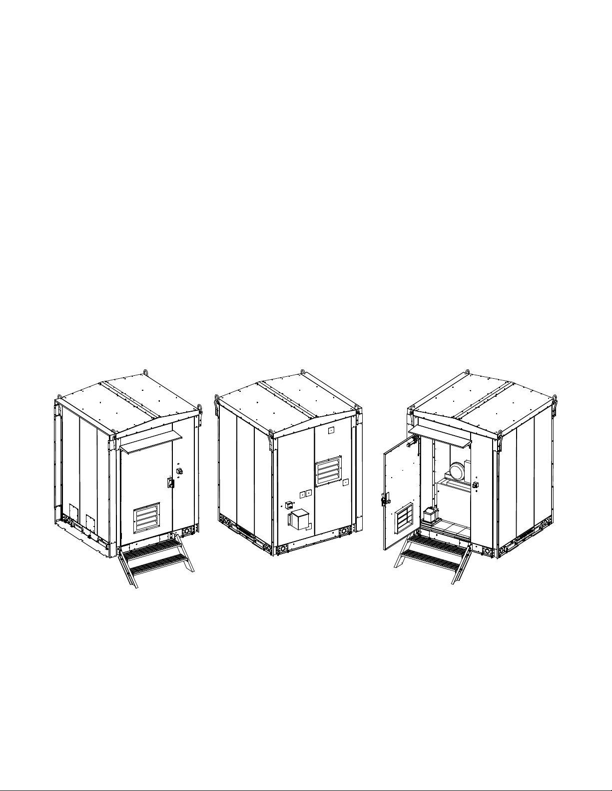
The XTE 802G Generator Room is a companion enclosure for the XTE 802 Walk-In-Cabinet (WIC). The XTE 802G can be used to
protect a 20 kW generator in snowy climates. See Figure 2-1 for overall views of the XTE 802G Generator Room. See Figure 2-2 for
an illustration of the XTE 802G mounted next to an XTE 802.
Figure 2-1: Overall Views of XTE 802G Generator Room
Page 12
Vertiv™ XTE 802G Generator Room Walk-In-Cabinet Description and Installation Manual
2
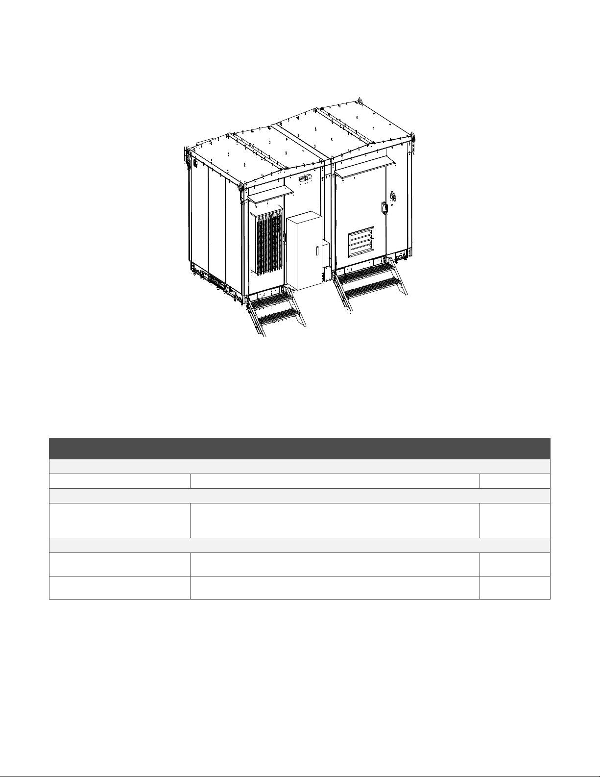
Front
Figure 2-2: Illustration of XTE 802G Generator Room Mounted Next to an XTE 802 Walk-In-Cabinet (WIC)
2.2 Part Numbers
Refer to Table 2-1 for applicable product part numbers.
Table 2-1: XTE 802G Generator Room Part Numbers and Descriptions
Part Number Description NEQ
XTE 802G Generator Room
F2019014 ATT 6X6 Generator Room BLD.44436
Foundation Options
D1000-0000-0101
(stand-alone application)
D1000-0010-0171 Combo Helical Platform - (1) Platform, (2) Stairs, (4) 8" x 7' Helical Piers with Leveling
D1000-0010-0179 Combo Concrete / On the Ground Platform - (1) Platform, (2) Stairs, (3) Skis with Leveling
WIC Helical Foundation Kit – (4) WIC Corner Plates, (1) Two Step Stair, and (4) 6” x 7’ Helical
Piers with Leveling Hardware.
(two required, one for the XTE 802 and one for the XTE 802G)
Combo Platforms
Hardware
Hardware
NEQ.19785
NEQ.44467
NEQ.44466
Page 13

Vertiv™ XTE 802G Generator Room Walk-In-Cabinet Description and Installation Manual
3
2.3 Application
The XTE 802G Generator Room is designed to house and protect a Kohler 20 kW diesel generator.
• The XTE 802G Generator Room is designed to provide secure and water-tight housing for the generator and associated
equipment including the generator battery.
• The XTE 802G Generator Room depends upon a proven structural system and integrated mechanical components.
• The XTE 802G Generator Room has several mounting options, primarily helical and concrete pier.
2.4 Standards Compliance
The XTE 802G Generator Room is designed to meet the following standards where applicable:
• CSA Certificate of Compliance #70193287.
- CLASS - C321111 - INDUSTRIAL CONTROL EQUIPMENT - Enclosures for Electrical Equipment
- CLASS - C321191 - INDUSTRIAL CONTROL EQUIPMENT - Enclosures for Electrical Equipment – US
- Enclosure Type 3R
NOTE!
APPLICABLE REQUIREMENTS
• National Building Code - Canada, 2005.
• National Building Code - USA, 2012.
• ASTM A653 - Galvanized Steel.
• Welding Conformance to CWB - CSA Standard W47.1 and AWS – D1.2, D1.3 and D1.6.
• Designed to meet Seismic Zone 4, water intrusion, impact resistance.
• Telcordia GR487 compliant for corrosion and ultraviolet radiation.
This unit is intended for industrial and/or power distribution equipment applications. These components are
intended for the installation of industrial electrical equipment and/or power distribution equipment where the complete
assembly is approved for installation in non-hazardous locations in accordance with the National Electric Code (NEC) and
Canadian Electric Code (CEC).
a) CSA C22.2 No, 94.1-07 / UL 50 12th Ed (Harmonized) Enclosures for Electrical Equipment, Non-Environmental
Considerations.
b) CSA C22.2 No. 94.2-07 / UL 50E 1st Ed (Harmonized) Enclosures for Electrical Equipment, Environmental
Considerations.
• Electrical certification as per CSA and NFPA70 (NEC) requirements.
• Installation method compliant to AT&T TP76300.
2.5 Safety Listed AC or DC Components
A typical XTE 802G Generator Room only utilizes listed or recognized components for the United States and/or Canada.
Page 14

Vertiv™ XTE 802G Generator Room Walk-In-Cabinet Description and Installation Manual
4
2.6 Dimensions, Weights, and Physical Specifications
Dimensions
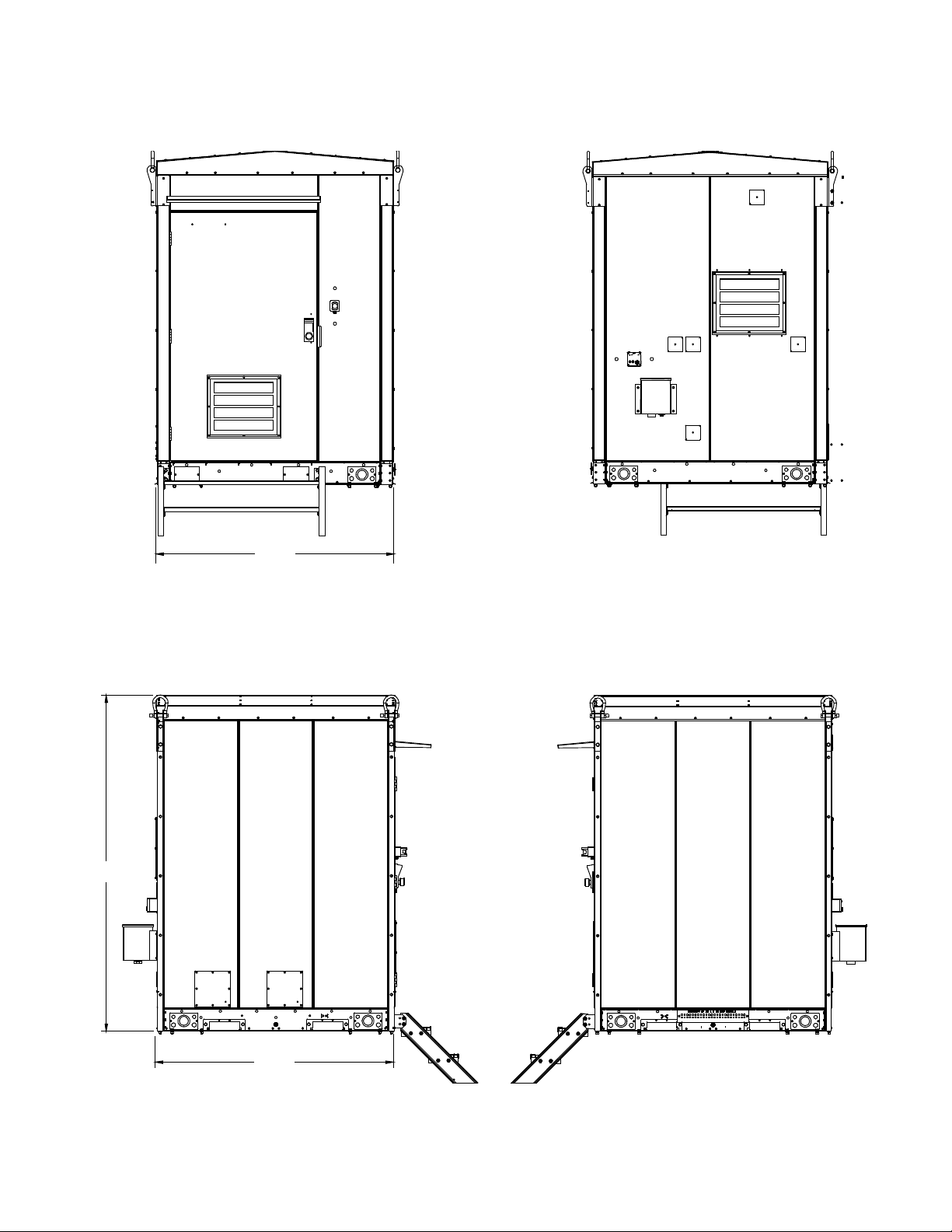
• See Figure 2-3 for overall dimensions.
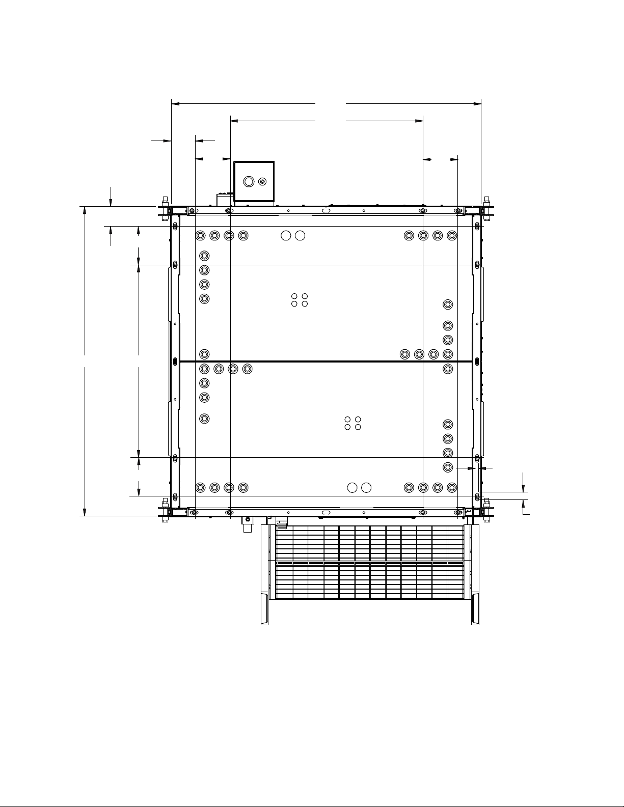
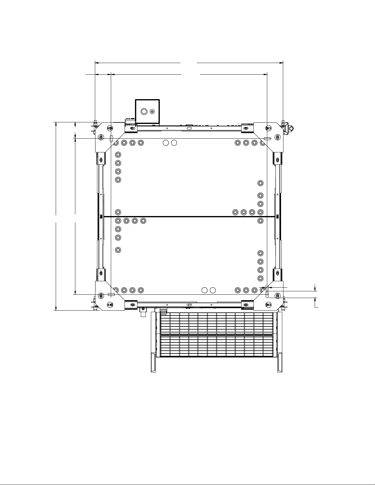
• See Figure 2-4 for mounting hole dimensions without corner plates and Figure 2-5 for mounting hole dimensions with corner
plates.
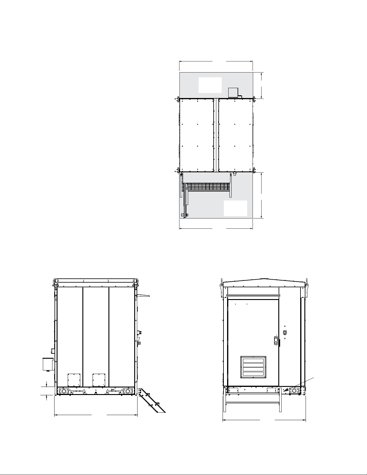
• See Figure 2-6 for working space clearances.
• See Figure 2-7 for base dimensions.
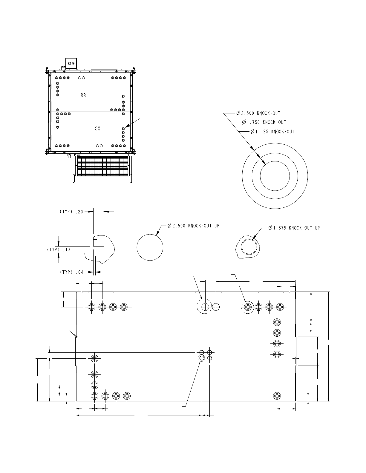
• See Figure 2-8 and Figure 2-9 for conduit knockout locations and dimensions.
Specifications
• External Dimensions – 80” x 80” x 113”
• Internal Height – 96.5"
• Internal Width – 71.4"
• Internal Length – 71.4"
• Weight – Empty: 2400 lbs.
As Installed: 4750 lbs.
• One (1) hour fire rating.
• Common equipment kit (lighting, etc.).
• Fully integrated internal grounding system.
• Externally mounted color matched unistrut channels on each lifting strap for mounting external equipment.
• Color – Pebble-Gray, RAL7032.
• Finish – Standard finish is multistage dry powder polyester paint for maximum durability and performance against corrosion.
Optional exterior finishes also available upon request.
Page 15
5
Figure 2-3: Overall Dimensions
Notes:
1. All dimensions are in inches,
unless otherwise specified.
80.00
Left Side
Right Side
113.06
80.00
Front
Rear
Vertiv™ XTE 802G Generator Room Walk-In-Cabinet Description and Installation Manual
Page 16
Vertiv™ XTE 802G Generator Room Walk-In-Cabinet Description and Installation Manual
6
2.00
80.26
80.26
Figure 2-4: Mounting Hole Dimensions (without corner plates)
50.00
6.07
5.14
10.00
49.97
9.06
9.06
Bottom View
10.00
Front
Notes:
1. All dimensions are in inches,
unless otherwise specified.
0.81
Page 17
7
Figure 2-5: Mounting Hole Dimensions (with corner plates)
Notes:
1. All dimensions are in inches,
unless otherwise specified.
82.99
2.43
Vertiv™ XTE 802G Generator Room Walk-In-Cabinet Description and Installation Manual
82.99
7.07
7.07
68.85
68.85
Bottom View
1.13
Front
Page 18
Vertiv™ XTE 802G Generator Room Walk-In-Cabinet Description and Installation Manual
8
Top View
Notes:
1. All dimensions are in inches,
unless otherwise specified.
36
48
80.00
80.00
Working
Space
Working
Space
Notes:
1. All dimensions are in inches,
unless otherwise specified.
Base
80.00
Front
80.00
7.59
Left Side
Figure 2-6: Working Space Clearances
Figure 2-7: Base Dimensions
Page 19
9
Figure 2-8: Conduit Knockout Locations in Base Pan
Bottom Cover Panel Conduit Knockout Locations and Dimensions
20X Detail B
Bottom View
Typ. Conduit Knockout
(see Detail B)
Front
2x
5.35
3x 5.30
14.73
14.92
2x 3.70
1.85
1.94
43.36 2.70
6.40 3x 3.70
6x 3.70
1.85
6.40
3x 3.70
2x 9.92
2x 12.34
2x 0.29
37.84
10.55
6.40
3.63
27.43
See Detail C
See Detail B
See Detail A
See Detail D
Detail A
2X Detail C
4X Detail D
Notes:
1. All dimensions are in inches,
unless otherwise specified.
Vertiv™ XTE 802G Generator Room Walk-In-Cabinet Description and Installation Manual
Page 20
Vertiv™ XTE 802G Generator Room Walk-In-Cabinet Description and Installation Manual
10
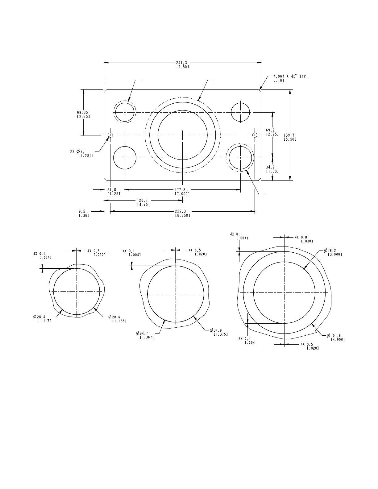
Notes:
1. All dimensions are in mm [inches].
2. All dimensions are to outside surface.
See Detail A
See Detail C
See Detail B
2X Detai l A
2X Detail B
Detail C
Figure 2-9: Base Side Plate Conduit Knockout Dimensions
Page 21

Vertiv™ XTE 802G Generator Room Walk-In-Cabinet Description and Installation Manual
11
2.7 Features and Options
Perspective Views
For illustrations of the XTE 802G, refer to the following.
• Refer to Figure 2-10 for perspective views with major features identified.
• Refer to Figure 2-11 for wall detail views.
• Refer to Figure 2-12 for top view of floor; including floor cable entry ports locations.
• Refer to Figure 2-13 for door intrusion switch location.
Construction
Welded galvanized steel construction with outstanding impact and corrosion resistance.
• Interlocking steel panels construction.
• Walls, floor and ceiling are made of 14 gauge steel.
• Ceiling joists with 12 gauge steel.
• Floor Load: 200 pounds per square foot minimum (uniform with full-support foundation).
• Roof Live and Impact Load: 300 PSF (maximum).
• Wind Speed: 180 mph.
Protection
Powder coat finish. Meets GR487 Telcordia mechanical and environmental standards for telecom cabinets.
• Protects against rain, sleet, snow, splashing water and damage from external ice formation.
• Optional exterior finishes including brick, stone and exposed aggregate are available upon request.
Mounting Base
Cable mounting base with 360 degree access to floor penetrations for easy conduit and cable entries into the XTE 802G Generator
Room. See
Figure 2-7 on page 8.
• Fork lift tubes on left and right sides of cabinet.
• Base includes steel cover plates front and back to accommodate cabling.
Common Equipment Kit
• Interior -48 VDC Lights
• Optional +24 VDC Smoke Detector
• Door Contacts
• Halo ground, interior isolated copper ground bar, H taps for ground terminal and external isolate ground bar, ground entry /
exit plate as per ATT grounding specification.
Page 22

Vertiv™ XTE 802G Generator Room Walk-In-Cabinet Description and Installation Manual
12
Access Door and Hardware
• Type: 16 gauge galvanized steel commercial grade insulated door.
• Size: 48" x 84" outward opening.
• Frame: 16 gauge galvanized steel frame.
• Door Lock: KABA Simplex L1000 Series, Model 1021B, Mechanical w/Best core.
• Hinges: (3) stainless steel with non-removable pin (per door).
• Door Holder: positive engagement latch with bumper stop.
• Closer: adjustable-hydraulic.
• Drip Cap: 12" drip cap above doorway.
Master Ground Bar (MGB)
The XTE 802G contains one (1) 24-position galvanized steel Master Ground Gar (MGB) mounted to the outside of the right side of the
base assembly. The all-metal structure of the XTE 802G is bonded together using the PANI method for grounding.
Ground Bar (Interior)
A ten (10) position ground bar is located at the inside rear of the XTE 802G. This ground bar is mounted on isolators. The default
ground lug geometry is two hole with 1/4” post and 5/8” spacing.
NOTE!
Two (2) hole lugs are required on all ground bar terminations.
Lifting
The XTE 802G Generator Room is equipped with one lifting lug at the top of each corner that allow it to be lifted and lowered into
position. The base is also equipped with fork lift pockets that allow the use of a forklift to offload and lower to the mounting base at
the site.
Door Intrusion Alarm Switch
A door intrusion alarm switch is provided. See Figure 2-13 for location and “Door Intrusion Alarm Switch Operation” on page 21 for
operation.
Alarms
The XTE 802G Generator Room is equipped with a door intrusion alarm switch. This switch can be wired to the alarm block located
on the XTE 802 Walk-In-Cabinet (WIC). The intrusion alarm triggers whenever the door is opened. It can be disabled by pulling the
alarm plunger completely forward.
Light Switch
A light switch is provided for the three (3) interior ceiling mounted LED lights. The light switch is located to the right of the door as
you enter.
Cable Entry Ports
• The XTE 802G has one (1) cutout in the floor which is equipped with Roxtec 4/4 EzEntry ports (see Figure 2-12 for location).
• The XTE 802G also contains a floor access plate which contains four (4) 1.37 inch conduit knockout holes (see Figure 2-12
for location).
• The XTE 802G base pan also includes conduit knockouts (see Figure 2-8 on page 9).
Page 23

Vertiv™ XTE 802G Generator Room Walk-In-Cabinet Description and Installation Manual
13
Working Space Requirements
See Figure 2-6 on page 8 for working space requirements.
Foundation Options
Helical Foundation Kit - Single Point Leveling (P/N D1000-0000-0101)
(for Mounting XTE 802G Separate from the XTE 802) (Two Required)
Consists of four (4) self drilling helicals, four (4) corner plates, leveling hardware, and stairs. Each helical is 6 inches in diameter and 7
feet in length. One helical will be located in each corner and will be drilled into the ground to 11 inches of grade (on the door side of
the unit if on a slope). One leveling hardware set will be installed in each helical, then the four (4) corner plates will be installed on top
of the leveling hardware. The unit will then be bolted to the corner plates using the appropriate provided hardware. The stairs are
then attached to the unit.
NOTE!
For grounding purposes, NEC requires a minimum of 10 vertical feet of helical in the ground.
Combo Foundation Options
Combo Helical Platform (P/N D1000-0010-0171)
If ordered through CEEOT, this platform will ship to the site completely configured with XTE 802 and XTE 802G including all conduit
and cabling. Consists of four (4) self drilling helicals, one (1) platform, two (2) stairs, and leveling hardware. Each helical is 8 inches in
diameter and 7 feet in length. Each helical will be drilled into the ground to 6 inches of grade (on the door side of the unit if on a
slope). Four leveling hardware sets will be installed in each helical, then the platform will be installed on top of the leveling hardware.
The stairs are then attached to the XTE 802 and the XTE 802G.
NOTE!
Combo Concrete / On the Ground Platform (P/N D1000-0010-0179)
If ordered through CEEOT, this platform will ship to the site completely configured with XTE 802 and XTE 802G including all conduit
and cabling. Platform ships complete. Consists of three (3) skis, one (1) platform, two (2) stairs, and leveling hardware. Platform is
simply lifted and set on the ground or concrete. Each ski has three leveling points for adjustments. The stairs are then attached to
the XTE 802 and the XTE 802G.
For grounding purposes, NEC requires a minimum of 10 vertical feet of helical in the ground.
Page 24

Vertiv™ XTE 802G Generator Room Walk-In-Cabinet Description and Installation Manual
14
Insulated Roof
WIC Interconnect
Panels and
Hardware
Exterior Ground Bar
Front
Front
Air
Intake
Lifting Hinges (4)
Access
Panels
Wide
Door
E-Stop
Switch
2-inch Insulated Wall
Panels with 2-inch Air Gap
Rear
Rear
Removable Cable
Entry Covers
Access
Panels
Forklift Pockets
Generator Radiator
Exhaust Vent
Alarm Panel
Fill Box
Figure 2-10: Perspective Views with Major Features Identified
Page 25

15
Figure 2-11: Wall Detail Views (cont’d on next page)
Vertiv™ XTE 802G Generator Room Walk-In-Cabinet Description and Installation Manual
Page 26

Vertiv™ XTE 802G Generator Room Walk-In-Cabinet Description and Installation Manual
16
Figure 2-11: Wall Detail Views (cont’d from previous page, cont’d on next page)
Page 27

Vertiv™ XTE 802G Generator Room Walk-In-Cabinet Description and Installation Manual
17
Figure 2-11: Wall Detail Views (cont’d from previous page, cont’d on next page)
Page 28

Vertiv™ XTE 802G Generator Room Walk-In-Cabinet Description and Installation Manual
18
Figure 2-11: Wall Detail Views (cont’d from previous page)
Page 29

19
Figure 2-12: Top View of Floor and Floor Cable Entry Ports
Roxtec
Conduit
Plate
Front Door
Empty
Generator
Battery
Front Door
With Generator Installed
Door Intrusion Switch
Vertiv™ XTE 802G Generator Room Walk-In-Cabinet Description and Installation Manual
Figure 2-13: Door Intrusion Switch Location
Page 30

Vertiv™ XTE 802G Generator Room Walk-In-Cabinet Description and Installation Manual
20
Provides information that will help the project engineer determine an appropriate use and location for
the XTE 802G, including associated foundation options.
Front Door
21
Describes the front door and operation of the front door intrusion alarm switch.
Installation Considerations
22
Provides installation overview.
Describes the transportation and storage requirements, the safe handling of the XTE 802G, and the
procedures to install the XTE 802G and associated foundation options.
Provides an installation diagram to assemble the sheet metal frame furnished to fill in the gap between
the installed XTE 802 and XTE 802G.
Sealing Cable Entries
45
Provides methods for sealing cable entries.
Grounding the XTE 802G
46
Describes the grounding requirements for the XTE 802G.
Provides DC wiring information for the interior DC lights and optional DC smoke detector.
OSP Cables
55
Provides procedures for preparing the cable sheaths and routing the cables within the XTE 802G.
Alarm Wiring
56
Describes the wiring for the XTE 802G alarms.
3 Sequence of Procedures
3.1 General
Perform the procedures in Table 3-1 (in the order listed) to fully install the XTE 802G.
Other practices and manufacturer’s documents will be required to complete the installation of the system. This includes, but is not
limited to:
• OSP cable fishing, sealing, grounding, splicing, and termination.
• Equipment manufacturer’s drawings and documentation.
• Refer also to…
- SD-2019014-01 (XTE 802G Schematic Drawings).
- J-2019014-01 (XTE 802G Job Drawings)
Table 3-1: Sequence of Procedures
Section in this Document Starting on Page Description
Product Description 1
XTE 802G Placement 24
Installing Interconnect Frame 43
DC Power 52
Page 31

Vertiv™ XTE 802G Generator Room Walk-In-Cabinet Description and Installation Manual
21
Front Door Intrusion Alarm Switch View
4 Front Door
4.1 Safety Precautions
DANGER! RISK OF ELECTRICAL SHOCK, AC
Proper actions, include, but not limited to:
• Verify before contacting the XTE 802G that no current leakage or ground fault condition is present.
• Verify a proper ground is in place.
WARNING! RISK OF EXPLOSION
For safety reasons, never restrict or block the airflow through the door or entry panel ventilation openings.
4.2 Locking Mechanism
The front door is equipped with a KABA Simplex L1000 Series, Model 1021B, Mechanical w/Best core door lock.
4.3 Securing Mechanism
The front door is equipped with a positive engagement latch with bumper stop to secure the door in an open position and an
adjustable-hydraulic closure.
4.4 Door Intrusion Alarm Switch Operation
The front door is equipped with a door intrusion alarm switch. The intrusion alarm switch can be connected to the alarm block
located on the XTE 802 Walk-In-Cabinet (WIC). If connected to an alarm sending device, an alarm can be sent whenever the front
door is opened. The intrusion alarm can be disabled while performing routine maintenance as described in the following procedure.
Refer to Figure 2-13 on page 19 for location of the intrusion alarm switch. Refer to Figure 4-1 for an illustration of the intrusion alarm
switch.
Procedure
1. Open the front door. If connected properly, the intrusion alarm activates.
2. Pull the plunger on the switch to silence the alarm.
3. The intrusion alarm can be reset by pushing the plunger back in, or by closing the front door.
Figure 4-1: Intrusion Alarm Switch
Page 32

Vertiv™ XTE 802G Generator Room Walk-In-Cabinet Description and Installation Manual
22
5 Installation Considerations
NOTE!
If holes are drilled into the exterior of this XTE 802G and not filled using a seal tight connector, the manufacturer’s
warranty will be void.
5.1 Important Safety Instructions
DANGER! Adhere to the “Important Safety Instructions” starting on page vi.
5.2 Installation Overview
The following is the recommended sequence for the installation and start-up procedures. The sequence may change according to job
and site conditions.
• Ensure all site drawings and approvals are in place.
• Obtain the recommended tools and test equipment.
• Read “Important Safety Instructions” starting on page vi carefully.
• Check that all the equipment and materials have been delivered.
• Proceed with the physical installation of the XTE 802G.
• Install and verify ground cables.
• Install and verify the DC power.
• Route, splice, and verify the OSP cables.
• Install and verify the alarm cables.
Page 33

Vertiv™ XTE 802G Generator Room Walk-In-Cabinet Description and Installation Manual
23
5.3 Tools and Test Equipment Required for Installation
The following tools, test equipment and materials are required for the physical installation of the XTE 802G:
• Non-contact voltage detector
• Digital multimeter (DMM), 0 to 200 V dc, 0 to 300 V ac
- Digital clamp-on meter, 0 to 30 A dc, 0 to 60 V ac, recommended
• Torque wrench
• Ratchet drive, extensions, sockets
• Carpenter’s level
• Lineman’s scissors
• Lineman’s strippers
• Lineman’s cutters
• Appropriate crimping tool with dies
• Electrician’s insulated screwdrivers, Phillips, No. 1 and 2
• Electrician’s insulated screwdrivers, flat-blade, small and large
• Insulated nut drivers for battery installation.
• Silicone sealant
• NO-OX-ID-A or approved equivalent
Outside the scope of this document are the tools to fish, splice, and terminate OSP cables.
Equipment associated with lifting the XTE 802G by the eyebolts is listed separately, in a subsequent section.
Page 34

Vertiv™ XTE 802G Generator Room Walk-In-Cabinet Description and Installation Manual
24
6 XTE 802G Placement
6.1 Overview
This section contains the procedures required for physical installation of the XTE 802G.
6.2 Site Selection
Obtain rights-of-way and other permits (building permit, electrical permit, etc.), depending on local codes and authorities, prior to
installing the XTE 802G.
The XTE 802G is to be installed using one of the following approved foundation kits and options:
1. WIC Helical Foundation Kit - Helicals screw into the ground 6 feet removing the need for a ground ring. Two kits required,
one for the XTE 802 and one for the XTE 802G.
2. Combo Helical Platform - Helicals screw into the ground 6 feet removing the need for a ground ring.
3. Combo Concrete / On The Ground Platform - To be installed on grade or on concrete.
Site Location Considerations
Consider the following when deciding on the location for the XTE 802G.
• Place the XTE 802G on servitudes, on dedicated (recorded) easements, or on property owned by the company. Avoid any
unrecorded easements.
• Use public road and street rights of way only where there is enough space to place the XTE 802G and provide safe working
conditions. The XTE 802G should be easily accessible with adequate parking to ensure safety for people and vehicles. Place
the XTE 802G where it will not create a visual or physical obstruction to either vehicles or pedestrians.
• Select locations that will minimize accidental or intentional vandalism. Consider the use of protective posts/bollards when
the XTE 802G is located near parking areas where vehicles could back into it.
• Do not place the XTE 802G in ditches or areas subject to flooding.
• Figure 2-6 on page 8 shows the minimum working space allowed between the XTE 802G and any obstruction including
fences, hedges, etc. Working space consists of adequate area for craft personnel to perform work and maintenance
procedures as defined in the National Electric Code (NEC).
• Where ordinances or other standards require that the XTE 802G be placed behind vegetation, preference should be given to
evergreens that will not produce leaves, sticky pollen or waste that could fall and clog the climate control units vents.
• If the area is subject to freezing temperatures, be sure to comply with the local building codes and footing requirements to
eliminate the possibility of frost heave.
• Minimize snow buildup around the XTE 802G and its externally mounted components.
• Placement should support access for snow removal equipment in the event of a snow/ice storm.
Page 35

Vertiv™ XTE 802G Generator Room Walk-In-Cabinet Description and Installation Manual
25
11”
6.3 Foundation Kit Installation
6.3.1 Helical Foundation Kit Installation (P/N D1000-0000-0101)
Helical Foundation Kit Installation Procedure
1. Assemble the universal driving tool on the correct Kelly bar adapter.
2. Connect Kelly bar adapter to Kelly bar on the drive head.
3. Move drive tool assembly to first helical and attach universal driving tool to helical plate paying attention to keeping the Kelly
bar as centered in the helical as possible. The leveling hardware can be used for this temporary attachment.
4. Lift helical upright allowing it to swing free of the ground.
5. Maneuver the helical directly over the installation point.
6. Lower the helical until the point of the helical is forced into the ground on target.
7. Screw helical 12 inches into the ground and plumb using a level on 2 sides 90 degrees from each other.
8. Continue screwing the helical into the ground while correcting the Kelly bars orientation so the helical embeds itself straight.
A ground man can be of assistance in keeping the foundation plumb during the installation.
9. Drive the helical until the helical plate is 11 inches above grade orientated as shown in Figure 6-1. Stop the driving tool
assembly. Disconnect the universal driving tool from the helical plate.
Figure 6-1: Diagram of Properly Installed Pier
Page 36

Vertiv™ XTE 802G Generator Room Walk-In-Cabinet Description and Installation Manual
26
10. Repeat steps 3 through 9 for all helicals paying attention to helical plate orientations and to accomplish 68.85 inch centers
between all four helicals. See Figure 6-2.
Figure 6-2: Helical Plate Orientations and Center to Center Adjustments
11. Install leveling hardware in the center on each helical. Each helical has one set of leveling hardware and each set of leveling
hardware consists of one threaded rod, four nuts, eight washers, and four lock washers. See Figure 6-3.
Figure 6-3: Install Leveling Hardware
Page 37

Vertiv™ XTE 802G Generator Room Walk-In-Cabinet Description and Installation Manual
27
12. Install the four corner plates on the leveling hardware, one in each corner. See Figure 6-4.
Figure 6-4: Install Four Corner Plates
13. Level and secure all the leveling hardware on the corner plates and helicals, paying attention to 68.85 inch centers. The
leveling hardware should not be installed outside the 3 inch radius of the helical pipe. The corner plates have elongated
holes for 2 inches of play. There is a lot of room for adjustments to accomplish the 68.85 inch centers. See Figure 6-2 and
Figure 6-5.
Figure 6-5: Helicals and Corner Plates
14. Lift and set XTE 802G on Helical Foundation Kit. Be sure to bolt the XTE 802G base to the corner plates prior to releasing all
of the weight of the XTE 802G on the corner plates. See “XTE 802G Lifting and Placement Procedures” starting on page 39.
15. Once all hardware is installed connecting the XTE 802G base to all corner plates, tighten and secure all the hardware.
16. Install the stairs using the provided hardware.
The helical foundation is designed to minimize soil disturbance and time involved for installation compared to other types of
foundations. The minimum requirements for properly installed helical pier are 1) to achieve penetration so the pier’s top base plate is
11 inches above grade and 2) achieve a minimum torque value of 3,000 foot-pounds. A maximum torque value of 15,000 foot-pounds
should be used. In the event the helical foundation cannot be installed per the standard procedure above, one of the following
Alternative Procedures should be used.
Page 38

Vertiv™ XTE 802G Generator Room Walk-In-Cabinet Description and Installation Manual
28
Alternative Installation Procedure #1 (6 Inch Auger)
1. Using a 6 inch auger, drill to a depth of 5 to 7 feet while minimizing enlargement of the bore. Drill the pier into the hole using
the standard methodology and parameters.
2. Fill and tamp any space around the top of the helical with dirt or small gravel.
Alternative Installation Procedure #2 (New Location)
In the event the base-plate is more than 11 inches above grade, due to subsurface conditions including bedrock, boulders and other
immovable objects;
1. Consider changing the location several feet while maintaining the required minimum antenna separation requirements.
Follow the steps of appropriate procedures above.
NOTE!
If more than one helical is unable to be driven to the required depth, please consult Vertiv engineering. For
grounding purposes, NEC requires a minimum of 10 vertical feet of helical in the ground. Consult the NEC to determine if a
ground ring is required for your installation.
6.4 Combo Platform Installation
6.4.1 Combo Helical Platform Installation (P/N D1000-0010-0171)
This platform is designed to be installed on helicals and it accommodates both the XTE 802 and XTE 802G. The default location for
the XTE 802G is to the right of the XTE 802 next to the ATS but the XTE 802G can be mounted on either side of the XTE 802 to
support any site layout. All conduits and cabling is installed at WWT so a completely configured platform can be installed at the site.
Simply install the helicals in the ground then lift and set the platform onto the helicals. See Figure 6-6.
Combo Helical Platform Installation Procedure
1. Assemble the universal driving tool on the correct Kelly bar adapter.
2. Connect Kelly bar adapter to Kelly bar on the drive head.
3. Move drive tool assembly to first helical and attach universal driving tool to helical plate paying attention to keeping the Kelly
bar as centered in the helical as possible. The leveling hardware can be used for this temporary attachment.
4. Lift helical upright allowing it to swing free of the ground.
5. Maneuver the helical directly over the installation point.
6. Lower the helical until the point of the helical is forced into the ground on target.
7. Screw helical 12 inches into the ground and plumb using a level on 2 sides 90 degrees from each other.
8. Continue screwing the helical into the ground while correcting the Kelly bars orientation so the helical embeds itself straight.
A ground man can be of assistance in keeping the foundation plumb during the installation.
9. Drive the helical until the top of the helical plate is 7 inches above grade. Stop the driving tool assembly. Disconnect the
universal driving tool from the helical plate.
10. Repeat steps 3 through 9 for all helicals paying attention to helical plate orientations and to accomplish 74 inch and 86 inch
centers between all four helicals. See Figure 6-6.
11. Install leveling hardware in each helical. Each helical has four sets of leveling hardware and each set of leveling hardware
consists of one threaded rod, four nuts, eight washers, and four lock washers. Leave the top washer, lock washer, and nut off
until platform is set.
Page 39

Vertiv™ XTE 802G Generator Room Walk-In-Cabinet Description and Installation Manual
29
12. Lift and set the platform onto the leveling hardware and level the platform.
13. Install the top washer, lock washer, and nut on all threaded rods to secure the platform.
14. Install the stairs on the XTE 802 using the provided hardware.
15. Install the stairs on the XTE 802G using the provided hardware.
The helical foundation is designed to minimize soil disturbance and time involved for installation compared to other types of
foundations. The torque value of a properly installed helical is a minimum of 3,000 foot-pounds and a maximum of 15,000 footpounds. In the event the helical foundation cannot be installed per the standard procedure above, one of the following Alternative
Procedures should be used.
Alternative Installation Procedure #1 (8 Inch Auger)
1. Using an 8 inch auger, drill to a depth of 5 to 7 feet while minimizing enlargement of the bore. Drill the pier into the hole using
the standard methodology and parameters.
2. Fill and tamp any space around the top of the helical with dirt or small gravel.
Alternative Installation Procedure #2 (New Location)
In the event the base-plate is more than 7 inches above grade, due to subsurface conditions including bedrock, boulders and other
immovable objects;
1. Consider changing the location several feet while maintaining the required minimum antenna separation requirements.
Follow the steps of appropriate procedures above.
NOTE!
If more than one helical is unable to be driven to the required depth, please consult Vertiv engineering. For
grounding purposes, NEC requires a minimum of 10 vertical feet of helical in the ground. Consult the NEC to determine if a
ground ring is required for your installation.
Page 40

Vertiv™ XTE 802G Generator Room Walk-In-Cabinet Description and Installation Manual
30
Figure 6-6: XTE 802 and XTE 802G Combo Helical Platform
Page 41

Vertiv™ XTE 802G Generator Room Walk-In-Cabinet Description and Installation Manual
31
6.4.2 Combo Concrete / Gravity Platform Installation (P/N D1000-0010-0179)
Combo Concrete Platform
This platform is designed to be set on concrete piers or pad and it accommodates both the XTE 802 and XTE 802G. The default
location for the XTE 802G is to the right of the XTE 802 next to the ATS but the XTE 802G can be mounted on either side of the XTE
802 to support any site layout. All conduits and cabling is installed at WWT so a completely configured platform can be installed at
the site. The legs use single-bolt leveling and are pre-installed. Simply lift and set on concrete piers or pad. Anchor holes are
provided for anchoring into the concrete. See Figure 6-7.
Combo Gravity Platform
This platform is designed to be set on the ground and it accommodates both the XTE 802 and XTE 802G. The default location for
the XTE 802G is to the right of the XTE 802 next to the ATS but the XTE 802G can be mounted on either side of the XTE 802 to
support any site layout. All conduits and cabling is installed at WWT so a completely configured platform can be installed at the site.
The legs use single-bolt leveling and are pre-installed. Simply lift and set on the ground. Anchor holes are provided for anchoring to
the ground if necessary. See Figure 6-8.
Grade Considerations
1. Ground/gravel should be normally dry and have good drainage.
2. Ground/gravel should be level or very close.
Concrete Pier Installation Considerations
1. Height of concrete piers must be constructed to grade level. If grade is not level, maintain an 18 inch height between grade
and the XTE 802G base on the side with the door. The 18 inch height is required for the stairs to mount properly.
2. Depth of concrete piers must be determined by region and take into consideration such items but not limited to depth of
frost line, soil type, general climate conditions, and site drainage.
3. 4000 PSI concrete strength should be considered as a minimum type of pier construction, but can vary based on local
architectural standards and approvals.
4. Maximum pier diameter: 30 inches
5. Minimum pier diameter: 18 inches.
6. Anchor bolts can be drilled in the concrete piers after the platform is set. Be sure to align all nine concrete piers under each
of three connection points under each of three skis. Anchor hardware could be anything between a 5/8 inch anchor (would
need washers) to a 1 inch anchor (no washers needed).
7. XTE 802 fully loaded is 6500 lbs.
8. Platform is 2050 lbs.
9. XTE 802G with full tank is 4750 lbs.
Existing Concrete Pad Considerations
1. Concrete area should be a minimum of 110" x 184" if the concrete is at grade level. This leaves one foot around the base of
the XTE 802 and XTE 802G and does not accommodate the stairs.
2. Concrete area should be a minimum of 134" x 184" if above grade to accommodate for the stairs.
3. XTE 802 fully loaded is 6500 lbs.
4. Platform is 2050 lbs.
5. XTE 802G with full tank is 4750 lbs.
Page 42

Vertiv™ XTE 802G Generator Room Walk-In-Cabinet Description and Installation Manual
32
Combo Concrete / Gravity Platform Installation Procedure
1. The On The Ground (Gravity) Foundation Kit ships assembled so lift and set it on grade or concrete in desired location.
2. Level the platform by adjusting the leveling hardware between the frame and the nine leveling points. Start by leveling the
four corners first then adjust the remaining leveling points. Once leveling is achieved secure the hardware.
3. Install the stairs on the XTE 802 using the provided hardware.
4. Install the stairs on the XTE 802G using the provided hardware.
Page 43

33
Figure 6-7: Combo Concrete Platform
Vertiv™ XTE 802G Generator Room Walk-In-Cabinet Description and Installation Manual
Page 44

Vertiv™ XTE 802G Generator Room Walk-In-Cabinet Description and Installation Manual
34
Figure 6-8: Combo Gravity Platform
Page 45

Vertiv™ XTE 802G Generator Room Walk-In-Cabinet Description and Installation Manual
35
6.5 Transportation and Storage
Safety Precautions
WARNING! PREVENT INJURIES, FROM LIFTING THE XTE 802G
Follow all local safety practices while lifting the XTE 802G. Safety equipment, signage, traffic control and all required Personal
Protective Equipment (PPE) shall be used.
Keep unnecessary personnel and bystanders clear of work areas at all times.
Do not lift the XTE 802G over people. Do not let anyone work, stand, or pass under a lifted XTE 802G.
Do not move or lift the XTE 802G with a door open.
Only properly trained and certified operators shall operate any crane or lifting equipment.
Do not allow the lifting equipment or XTE 802G to touch any electrical wiring or equipment.
Operate all lifting equipment within safety constraints, as defined by the manufacturer and local practices; for example, do not
exceed the capacity of reach.
Crane Operation:
Only properly trained operators shall operate the crane.
Do not operate the crane until all stabilizers are extended. The stabilizers must be in firm contact with the ground or other
adequate support structure. Do not retract or extend the stabilizers when the XTE 802G is suspended from the crane.
Only the crane rigging crew should set up the crane and rigging.
Do not exceed the lifting capacity of the crane.
Use all four (4) provided lifting points (eyes) at the top corners of the XTE 802G to lift the XTE 802G.
Use crane spreader frames to prevent XTE 802G framework warping due to side loading.
Never route straps, cables or chains through the fork-lift channels in the base for a vertical crane lift.
Do not use slings, clevises or shackles of insufficient capacity.
Forklift Operation:
Only properly trained operators shall operate the forklift.
Do not exceed the lifting capacity of the forklift.
Forklifts shall have a minimum fork length of 72 inches (183 cm).
Page 46

Vertiv™ XTE 802G Generator Room Walk-In-Cabinet Description and Installation Manual
36
DANGER! RISK OF ELECTRICAL SHOCK, GENERAL
Do not install equipment showing any physical damage. If packaging is damaged, do not accept receipt from the shipper.
CAUTION! PREVENT EQUIPMENT DAMAGE, PROPER HANDLING
Do not stack nor lay the XTE 802G on its side.
WARNING! RISK OF INJURY, FROM UNSECURED XTE 802G
Do not pull cables or terminate cables until XTE 802G has been properly secured in its mounted position.
CAUTION! PREVENT EQUIPMENT DAMAGE, FROM CONDENSATION
Until the XTE 802G is secured and sealed, weather protection shall be maintained to prevent moisture and condensation
from entering ports or openings into the conditioned space within.
General
For short-term storage, the XTE 802G should not be exposed to temperatures that exceed the temperature range of –40 °C (–40 °F)
to +70 °C (+158 °F).
For long-term storage, the XTE 802G and packaging should be kept dry and not be exposed to temperatures outside the range of –10
°C (+14 °F) to +40 °C (+104 °F).
Once packaging has been discarded and the XTE 802G has been securely placed in its mounted position, the XTE 802G may be
exposed to conditions from –40 °C (–40 °F) to +46 °C (+115 °F).
6.6 Unpacking and Preparing the XTE 802G at the Installation Site
Safety Precautions
DANGER! Do not install any additional equipment until the XTE 802G is secured in its mounted position.
CAUTION! TO AVOID EQUIPMENT DAMAGE:
DO NOT REMOVE the exterior packaging or wrap from the XTE 802G until the XTE 802G is transported to the installation
site. Control moisture and condensation inside the XTE 802G until it is turned up for service.
General
• The XTE 802G is shipped from the manufacturer with plastic wrap to protect the XTE 802G during shipment.
• If the external packaging appears excessively damaged, do not accept the unit from the shipper as interior damage may not
be apparent.
• CAREFULLY remove all packaging material from around the XTE 802G. Dispose of the packaging according to local
practices.
• On receipt at the site, inspect the XTE 802G to make sure there is no damage to equipment. Check the packing slip to make
sure all components are received. If any components are damaged or not received, contact your supervisor for further
instructions.
• Close and latch all doors in preparation for XTE 802G placement.
WARNING! Do not open any doors on the XTE 802G unless it is secured in its mounted position, or securely restrained
against unexpected movement or tipping.
Page 47

Vertiv™ XTE 802G Generator Room Walk-In-Cabinet Description and Installation Manual
37
6.7 Preparing to Lift the XTE 802G
General
Refer to “Transportation and Storage” on page 35.
Required Equipment When Using a Crane:
• A crane capable of lifting the shipped weight of the equipped XTE 802G plus a safety margin.
- 10,000 lbs (4536 kg), or greater.
• Four (4) wire-rope slings, 8-ft. (2.4 m) long (minimum). Slings should each have the capacity to support the entire shipped
weight of the equipped XTE 802G to prevent potential cascading failures.
- 8,000 lbs (3629 kg)
• Spreader frames are required for shorter slings to prevent XTE 802G framework damage due to side-loading forces at the
top corner lifting eyes. Lifting forces shall be vertical only and applied only at the lifting eyes.
• Four (4) connecting links (clevises), to attach the wire-rope slings to the XTE 802G lifting eyebolts. Connecting links should
each have the capacity to support the entire shipped weight of the equipped XTE 802G to prevent potential cascading
failures.
- 8,000 lbs (3629 kg)
• A 75-ft (20 m) rope, 5/8” (1.5 cm) in diameter, to use as a tagline. A tagline is used to guide the XTE 802G into position while
it is lifted and lowered.
Required Equipment When Using a Forklift:
• A forklift capable of lifting the shipped weight of the equipped XTE 802G plus a safety margin.
- 10,000 lbs (4536 kg), or greater.
• Forklifts shall have a minimum fork length of 72 inches (183 cm).
Preparing to Lift the XTE 802G Procedure
1. If not previously done, unpack the XTE 802G according to the instruction in “Unpacking and Preparing the XTE 802G at the
Installation Site” on page 36.
2. If XTE 802G base cable entry covers are installed, remove the bolts from the XTE 802G base cable entry covers and set aside
the covers and hardware for later re-use. See Figure 6-9.
Page 48

Vertiv™ XTE 802G Generator Room Walk-In-Cabinet Description and Installation Manual
38
Removable Base
Cable Entry Covers
Figure 6-9: Removing Base Cable Entry Covers
Page 49

Vertiv™ XTE 802G Generator Room Walk-In-Cabinet Description and Installation Manual
39
6.8 Lifting the XTE 802G
Safety Precautions
DANGER! The maximum XTE 802G weight when lifted shall not exceed equipment ratings!
Procedure (When Using a Crane)
1. Close and latch all doors before lifting and placing the XTE 802G.
2. Inspect the lifting eyebolts and ensure eyebolts and roof are secure and free of damage.
3. Install a clevis and shackle or a threaded shackle in each eyebolt at the top of the XTE 802G as shown in Figure 6-10.
4. Insert all four (4) 8 feet minimum lifting slings securely through all four clevises or shackles as shown in Figure 6-10. Never
route straps, cables or chains through the forklift channels in the base for a vertical crane lift.
NOTE!
eyebolts in a vertical direction.
NOTE!
NOTE!
5. Tie a 75-ft. rope to a lifting eyebolt so it can be used as a tag line.
6. Never work under the XTE 802G while it is suspended above the ground.
7. Lift the XTE 802G off the truck and place it into its mounted position using the tagline to guide it into position. Continue with
the “Placing the ” procedure on 41.
If slings are not long enough (8-ft. [2.4 m] or longer), use a spreader bar to be sure the cables pull on the lifting
It is important that the length of each sling allow for an angle 45 degree or more.
Failure to maintain a 45 degree angle or greater and using all four eyebolts will void any warranty or service claim.
Procedure (When Using a Forklift)
1. Close and latch all doors before lifting and placing the XTE 802G.
2. Lift the XTE 802G using the forklift pockets located in the base of the XTE 802G.
3. Never work under the XTE 802G while it is suspended above the ground.
4. Lift the XTE 802G off the truck and place it into its mounted position. Continue with the “Placing the ” procedure on 41.
Page 50

Vertiv™ XTE 802G Generator Room Walk-In-Cabinet Description and Installation Manual
40
Typical sling
arrangement
Shackle
Direction
of pull
The angle
between the sling
cables and the top
of the cabinet shall
not be less than 45°
Never use the sling without
clevises or shackles as this
may break the eyebolts
Shackle
Top of WIC
Lifting Brackets
and Shackles
(4 places)
Figure 6-10: Lifting the XTE 802G
Page 51

Vertiv™ XTE 802G Generator Room Walk-In-Cabinet Description and Installation Manual
41
6.9 Placing the XTE 802G
6.9.1 On Approved Foundation Kit
Approved Foundation Kits:
• WIC Helical Foundation Kit
• Combo Helical Platform
• Combo Concrete / On The Ground Platform
The following is a typical guide. Consult your company policies for your specific installation requirements.
Perform the following steps in placing and securing the XTE 802G.
Procedure
ALERT! During lifting, the XTE 802G must be lowered so that the XTE 802G is level and parallel to the piers. Place the XTE
802G so that it lines up with the bolt locations and clears any conduits.
1. Set XTE 802G on foundation kit. Be sure to install and secure provided hardware between XTE 802G base and foundation kit
prior to setting the full weight of the XTE 802G.
2. Check to be sure the XTE 802G is properly placed.
3. Loosen the slings or remove forklift so that the full weight of the XTE 802G rests on the foundation kit.
4. Secure the XTE 802G by bolting it to the mounting plates that are attached to the top of the piers using appropriate bolting
material. Add top washers and nuts to leveling hardware and tighten. See Figure 6-11.
NOTE!
washers. Two nuts and washers sandwich the pier top plate and the other two nuts and washers sandwich the XTE 802G
mounting plate.
5. Verify hardware between XTE 802G base and foundation kit is tight and secure.
6. Remove the slings, spreader bars, and tagline (if using a crane).
ALERT! If the XTE 802G will not be powered up for an extended period, place a heat source, such as two 120 VAC 150 W
incandescent lamps inside the XTE 802G to prevent condensation. Suspend lamps to prevent contact with any structures or
equipment inside the XTE 802G.
Each pier has four sets of leveling hardware. Each set of leveling hardware has one threaded rod and four nuts and
Page 52

Vertiv™ XTE 802G Generator Room Walk-In-Cabinet Description and Installation Manual
42
Threaded Rod into Pier
Sandwich WIC Mounting Plate Between
Top Sets of Washers and Nuts
Sandwich Pier Top Plate Between
Bottom Sets of Washers and Nuts
WIC Mounting Plates and Hardware
Figure 6-11: Bolting XTE 802G to Pier
Page 53

Vertiv™ XTE 802G Generator Room Walk-In-Cabinet Description and Installation Manual
43
7 Installing Interconnect Frame
A sheet metal frame is furnished to fill in the gap between the installed XTE 802 and XTE 802G. Refer to Figure 7-1 for assembly
details.
Figure 7-1: Interconnect Frame (cont’d on next page)
Page 54

Vertiv™ XTE 802G Generator Room Walk-In-Cabinet Description and Installation Manual
44
Figure 7-1: Interconnect Frame (cont’d from previous page)
Page 55

Vertiv™ XTE 802G Generator Room Walk-In-Cabinet Description and Installation Manual
45
8 Sealing Cable Entries and Openings with Factory Cover-
Plates
8.1 General
In keeping with best industry practices, seal all cable grommets penetrations against weather, rodent and insect intrusions.
It is extremely important to maintain a well-sealed XTE 802G. Failure to do so can jeopardize the enclosed electronic equipment, as
well as the proper functioning of the XTE 802G systems. All cable transitions into the XTE 802G must be properly sealed as required.
Refer to the following procedure to seal cable entries with duct sealing foam:
1. Route the cables into the XTE 802G through bottom-entry conduits (preferred) or through side-entry conduits in the XTE
802G base structure (if absolutely necessary). The bottom-entry and removable side-entry plates have pre-configured
knockout stampings to facilitate conduit connections.
2. Route the OSP cables into the XTE 802G by removing a Roxtec port frame from the finished floor inside the XTE 802G. Use
a fiberglass fish tape from a side-entry port to extend to below the Roxtec port. Reach down through the finished floor to the
fish tape, and use it to route pull cord or cables as required. Conduit knockouts are directly below each Roxtec port in the
XTE 802G base pan.
3. Route OSP cables to equipment through the Roxtec port frame, securing to cable rack and equipment frames as required.
4. Seal all conduit openings with Roxtec blocks, duct sealing foam or the equivalent against weather, animal and insect intrusion
into the XTE 802G.
5. Replace port covers, Roxtec port frames and any other material removed during installation.
6. Verify that cables are routed as required and that all cable entries are properly sealed.
8.2 Generator Installation
After installation of a generator in this enclosure, it is the end-user’s responsibility to seal the enclosure to maintain the rain-proof
rating.
Page 56

Vertiv™ XTE 802G Generator Room Walk-In-Cabinet Description and Installation Manual
46
9 Grounding the XTE 802G
9.1 Important Safety Instructions
DANGER! Adhere to the “Important Safety Instructions” starting on page vi.
9.2 Safety Precautions
DANGER! RISK OF ELECTRICAL SHOCK, GENERAL
All XTE 802G grounding must be installed and verified prior to connecting any power cables (AC or DC) and turning-up of
the XTE 802G.
Ensure that all NEC (National Electric Code), CSA (Canadian Electric Code) and local codes for safety and wiring are followed.
Consideration for corporate standards also apply.
9.3 General
All external ground wires shall only be terminated to the Master Ground Bar (MGB) located at the base of the right side of the XTE
802G (see Figure 9-1).
All internal ground wires shall be terminated to an interior ground bar prior to any externally derived electrical power being connected
to the XTE 802G (see Figure 9-2).
All XTE 802G grounding must be installed prior to turn up of XTE 802G.
• The internal XTE 802G frame and all attached equipment are factory grounded to the XTE 802G interior ground bar.
• A 2 AWG green conductor is factory connected from the XTE 802G interior ground bar to the Master Ground Bar (MGB)
located on the lower right exterior of the XTE 802G.
• The XTE 802G structure is separately grounded to the Master Ground Bar (MGB).
9.4 Master Ground Bar (MGB)
ALERT! Grounding should be accomplished according to local practices and in accordance with the latest NEC codes.
Refer to Figure 9-3, Figure 9-4, and Figure 9-5 for XTE 802G site grounding schemes.
Procedure
1. Connect one provided stranded cable from the Master Ground Bar (MGB) to site ground per local practices. Refer to Figure
9-1 for location.
2. The Master Ground Bar (MGB) is configured to terminate 2-hole lugs, 3/8” hardware, on 1” center spacing (see Figure 9-1).
3. Allow for a 0.125” minimum space between adjacent lugs.
9.5 Ground Bar (Interior)
See Figure 9-2.
Page 57

47
Figure 9-1: XTE 802G Master Ground Bar (MGB) Location
1.48
12X
.910
11X .920
4.00
24.00
24X .438
2X .438
24X .438 x .688 OBROUND
2X .56
1.56
2X
2.00
2.44
Master Ground Bar (MGB)
Location
Master Ground Bar (MGB)
Front
Vertiv™ XTE 802G Generator Room Walk-In-Cabinet Description and Installation Manual
Page 58

Vertiv™ XTE 802G Generator Room Walk-In-Cabinet Description and Installation Manual
48
Ground Bar
Front
Figure 9-2: XTE 802G Ground Bar (Interior) Location
Page 59

Vertiv™ XTE 802G Generator Room Walk-In-Cabinet Description and Installation Manual
49
(Contractor Installed)
(Contractor Installed)
To the tower ground.
Use one provided #2
stranded cable from the
master ground bar.
Terminate one provided
#2 AWG solid pre-lugged
cable from the master
ground bar to the ground
connection on each WIC
corner plate.
To WIC corner plate
on opposite side.
To WIC corner plate
on opposite side.
Helical
Anchors
Master Ground Bar
(right side)
Front
Grounding
Conductor
Size
Minimum Bending Radius (inches)
(Insulated RHH/RHW)
Solid
(Uninsulated)
Recommended Required
6 AWG 12 2 1-1/2
4 AWG 12 3 na
2 AWG 12 3 2
1/0 AWG 12 4 na
4/0 AWG 12 4 na
750 kcmil 12 7 na
XTE 802G Site Grounding (Helical Foundation)
Figure 9-3: XTE 802G Site Grounding Scheme (Helical Foundation)
Page 60

Vertiv™ XTE 802G Generator Room Walk-In-Cabinet Description and Installation Manual
50
Grounding
Conductor
Size
Minimum Bending Radius (inches)
(Insulated RHH/RHW)
Solid
(Uninsulated)
Recommended Required
6 AWG 12 2 1-1/2
4 AWG 12 3 na
2 AWG 12 3 2
1/0 AWG 12 4 na
4/0 AWG 12 4 na
750 kcmil 12 7 na
(Contractor Installed)
(Contractor Installed)
To the tower ground.
Use one provided #2
stranded cable from the
master ground bar.
Terminate one provided
#2 AWG solid pre-lugged
cable from the master
ground bar to the ground
connection on the frame
or beam.
Helical
Anchors
Master Ground Bar
(right side)
Front
XTE 802 and XTE 802G Combo Site Grounding (Helical Foundation)
Figure 9-4: Combo Site Grounding Scheme (Helical Foundation)
Page 61

Vertiv™ XTE 802G Generator Room Walk-In-Cabinet Description and Installation Manual
51
Grounding
Conductor
Size
Minimum Bending Radius (inches)
(Insulated RHH/RHW)
Solid
(Uninsulated)
Recommended Required
6 AWG 12 2 1-1/2
4 AWG 12 3 na
2 AWG 12 3 2
1/0 AWG 12 4 na
4/0 AWG 12 4 na
750 kcmil 12 7 na
XTE 802 and XTE 802G Combo Site Grounding
(Concrete / On the Ground Platform Foundation)
To the ground ring.
(Contractor Installed) (Contractor Installed)
To the tower ground.
Use second provided #2
stranded cable from the
master ground bar.
Use one provided #2
stranded cable from the
master ground bar.
(Contractor Installed)
Terminate one provided
#2 AWG solid pre-lugged
cable from the master
ground bar to the ground
connection on the frame
or beam.
Master Ground Bar
(right side)
Front
Figure 9-5: Combo Site Grounding Scheme (Concrete / On the Ground Platform Foundation)
Page 62

Vertiv™ XTE 802G Generator Room Walk-In-Cabinet Description and Installation Manual
52
10 DC Power
10.1 Important Safety Instructions
DANGER! Adhere to the “Important Safety Instructions” starting on page vi.
10.2 Safety Precautions
DANGER! RISK OF ELECTRICAL SHOCK, GENERAL
All ground connections must be installed and verified prior to connecting any power cables (AC or DC) and turning-up of the
XTE 802G.
When connecting any discrete power connection, make the connection first with the ground/return and break last with
ground/return.
Remove rings, metallic wrist bands, or bracelets, etc.
Do not install equipment showing any physical damage.
DANGER! RISK OF ELECTRICAL SHOCK, DC
A maintenance Battery Switch / Breaker does NOT isolate both legs of a battery circuit, nor do the batteries have a protective
fuse. Proceed with caution and use only insulated tools when working around batteries or any DC potential.
Always be sure that any connection points have been de-energized.
Fuses can produce sparks during interruption or clearing of a fault, so only use fuses provided with safety caps or enclosed
holders, where applicable.
10.3 General
Refer to “Grounding the XTE 802G” on page 46 for information on XTE 802G grounding.
Refer to the schematic diagram provided with the XTE 802G.
10.4 -48 VDC Interior Lights Wiring Block
Connect -48 VDC to the interior lights wiring block as shown in Figure 10-1.
Page 63

53
Figure 10-1: Interior Lights Wiring Block
Vertiv™ XTE 802G Generator Room Walk-In-Cabinet Description and Installation Manual
Page 64

Vertiv™ XTE 802G Generator Room Walk-In-Cabinet Description and Installation Manual
54
10.5 Optional +24 VDC Smoke Detector Wiring Junction Box
Connect +24 VDC to the optional smoke detector wiring junction box as shown in Figure 10-2.
Figure 10-2: Smoke Detector Wiring Junction Box
Page 65

Vertiv™ XTE 802G Generator Room Walk-In-Cabinet Description and Installation Manual
55
11 OSP Cables
11.1 Important Safety Instructions
DANGER! Adhere to the “Important Safety Instructions” starting on page vi.
11.2 Safety Precautions
DANGER! RISK OF ELECTRICAL SHOCK, OSP CABLES
If buried cables are used, check the cable sheath for voltage in accordance with local standards. If voltage is detected, do not
proceed with the installation. Contact the supervisor and do not proceed until the voltage hazard is eliminated.
11.3 General
Install OSP cables as required per site requirements.
11.4 Sealing Cable Entries
After cables are installed, refer to “Sealing Cable Entries” on page 45 and seal all cable entries.
Page 66

Vertiv™ XTE 802G Generator Room Walk-In-Cabinet Description and Installation Manual
56
Front Door Intrusion Alarm Switch
Note: This wiring of the intrusion switch results
in a Normally Closed (open on alarm) circuit.
12 Alarm Wiring
The XTE 802G is equipped with a door intrusion alarm switch. This switch can be wired to the alarm block located on the XTE 802.
See Figure 12-1. Refer also to the XTE 802 documentation.
Figure 12-1: Door Intrusion Alarm Switch Wiring
Page 67

Vertiv™ XTE 802G Generator Room Walk-In-Cabinet Description and Installation Manual
57
This page intentionally left blank.
Page 68

Vertiv™ XTE 802G Generator Room Walk-In-Cabinet Description and Installation Manual
58
CUSTOMER SERVICE (PRE-SHIPMENT)
Email
CustomerService.ESNA@Vertiv.com
Phone
1.800.800.1280 option 1
CUSTOMER SUPPORT CENTER (POST-SHIPMENT)
Email
ESNACustomerSupportCenter@Vertiv.com
Phone
1.800.800.1280 option 9
PRODUCTS
Email
AccountManagement.ESNA@Vertiv.com
For product pricing
[1]
and bid responses for custom configured DC
Management.
SPARE PARTS
DCpower.Spares@Vertiv.com
OSP.Spares@Vertiv.com
Phone
1.800.800.1280 option 5
DC POWER DEPOT REPAIR
Email
DCpower.Repair@Vertiv.com
Creates and processes RMAs for depot repair and refurbishment.
Phone
1.800.800.1280 option 5
Website
Vertiv.com/DCpowerRMA
INSTALLATION & AFTER MARKET SERVICES
Email
ESNA.FieldService@Vertiv.com
Provides quotes for engineering, furnishing and installation of DC
field services of existing DC equipment.
TECHNICAL SUPPORT
Email
DCpower.TAC@Vertiv.com
Answers technical product questions about DC power systems and
contractual agreements for repair.
Phone
13 DC Power, Outdoor Enclosure & Service Contacts
Phone
Email
1.800.800.1280 option 2
Call Customer Service for purchase order status, expediting
requests and order tracking.
After an order has shipped, contact our Customer Support Center
with post-shipment related questions, concerns or claims.
power systems and outdoor enclosures for customers and channel
partners (Reps, VARs & Distributors), contact Account
Pricing and purchase orders for spare parts, including but not
limited to breakers, cables, fuses, rectifier fans, misc. breaker and
fuse panels, enclosure fans, doors and switches, etc.
Determines repair and refurbishment lead times and pricing based
on warranties/contractual agreements.
Provides repair shipping information and status.
Phone
1.800.800.1280 option 5
1.800.800.5260
[1] Contact Spare Parts for parts and accessories.
power systems, telecom & IT equipment, cabling infrastructure, and
outdoor enclosures; determines status of warranties and
Page 69

Vertiv™ XTE 802G Generator Room Walk-In-Cabinet Description and Installation Manual
Connect with Vertiv on Social Media
https://www.facebook.com/vertivI
https://www.instagram.com/vertiv/
https://www.linkedin.com/company/vertiv/
https://www.twitter.com/vertiv/
Page 70

Vertiv.com | Vertiv Headquarters, 1050 Dearborn Drive, Columbus, OH, 43085, USA
© 2020 Vertiv Group Corp. All rights reserved. Vertiv™ and the Vertiv logo are trademarks or registered trademarks of Vertiv Group
Corp. All other names and logos referred to are trade names, trademarks or registered trademarks of their respective owners. While
every precaution has been taken to ensure accuracy and completeness here, Vertiv Group Corp. assumes no responsibility, and
disclaims all liability, for damages resulting from use of this information or for any errors or omissions. Specifications, rebates and
other promotional offers are subject to change at Vertiv’s sole discretion upon notice.
10011011_REVA
 Loading...