

Page 1

1
Vertiv I Liebert® ™ I User Manual
VRC Split System
VRC2 Series Rack Cooler
VRC3 Series Condensing Unit
User Manual
Page 2

Page 3

VRC Split System
User Manual
Version
V1.3
Revision date
Aug 26, 2020
BOM
31014128
Page 4

Page 5

Copyright by Vertiv Group Corp.
The content in this document is subject to change without notice. All rights, including rights of
translation, reproduced by printing, copying or similar methods and even of parts are reserved.
Violators will be liable for damages. All rights, including rights deriving from patent license or
registration of a utility model or design, are reserved. No part of this document may be reproduced or
transmitted in any form or by any means without the prior written consent of Vertiv Group Corp.
Notice
The purchased products, services and features are stipulated by the contract made between Vertiv
Group Corp. and the customer. All or part of the products, services and features described in this
document may not be within the purchasing scope or the usage scope. Unless otherwise specified in
the contract, all statements, information recommendations in this document are provided "AS IS"
without warranties, guarantees or representations of any kind, either express or implied. The
information in this document is subject to change without notice. Every effort has been made in the
preparation of this document to ensure the accuracy of the contents, but all statements, information
recommendations in this document do not constitute a warranty of any kind, express or implied.
Vertiv
United States
Australia & New
Indonesia
Malaysia
Singapore
Service Calls
Zealand
Service Calls
Service Calls
Service Calls
1 800 543 2378
Service Calls
0817 988 2288
19 211 1668
64674218
General Inquiries
1300 367 686
General Inquiries
General Inquiries
General Inquiries
1 800 543 2778
General Inquiries
021 251 3003
3 7884 5000
64674218
1 800 222 5877
1800 065 345
Romania: 800477000
Egypt, Bahrain: 390499717744
Croatia: 800989019
Greece: 80044146622
Qatar: 800100439
UAE: 800035702985
Ghana: 242426263
Saudi Arabia: 8008446628
Nigeria: 7080601125
Non-listed Countries: 49872327750
Turkey: 800448826888
Austria, Benelux, Czech Republic, France, Germany, Hungary, Ireland, Italy, Poland, Russia, Spain,
Sweden, Switzerland, UK, South Africa: 80011554499
Website: www.vertiv.com
For Technical Support, users may contact the nearest Vertiv local sales office or service center.
Page 6
Purpose of the Document
This document applies to the VRC2 series and VRC3 series of cooling solutions which maintain an optimal
environmental control mainly for technological ecosystems at minimal operating costs. This document gives
an overview of the technical specification. The figures used in this document are for reference only. Please
read this manual carefully.
Important Safety Instructions
The important safety instructions that should be followed during the installation and maintenance of the VRC
Split System are described in the following sections.
Read the manual prior to installation and operation of the unit. Only qualified personnel should move, install,
or service this equipment.
The user reads all of the precautions, compliance safety measures before working on the equipment. The
unit control must be used exclusively for the purpose for which it is intended; the manufacturer takes no
liability for incorrect use or modification to the unit control.
This manual is retained for the entire service life of the machine. The user must read all of the precautions,
danger, warnings cautionary measures mentioned in the manual prior to carrying out any operations on the
machine. Before performing any maintenance operation, switch off the machine to eliminate risks such as
electrical shocks, burns, automatic restarting, moving parts remote control.
Adhere to all the Warnings and Cautionary measures included in this manual. In the following sections, look
at the various cautionary measures and warnings that need to be read carefully prior to installing or operating
the system.
WARNING! Risk of improper wiring, piping, moving, lifting and handling. Can cause equipment damage,
serious injury or death. Installation and service of this equipment should be done only by qualified
personnel who have been specially-trained in the installation of air-conditioning equipment and who
are wearing appropriate, OSHA-approved PPE.
WARNING! The components of the unit are comparatively large and heavy. Therefore, there may be a
risk when the containment collapses. The collapse may result in physical injury, fatality and damage to
the equipment.
WARNING! Arc flash and electric shock hazard. Open all local and remote electric power-supply
disconnect switches, verify with a voltmeter that power is Off and wear appropriate, OSHA-approved
personal protective equipment (PPE) per NFPA 70E before working within the electric control enclosure.
Failure to comply can cause serious injury or death. Customer must provide earth ground to unit, per
NEC, CEC and local codes, as applicable. Before proceeding with installation, read all instructions, verify
that all the parts are included and check the nameplate to be sure the voltage matches available utility
power. The Liebert® controller does not isolate power from the unit, even in the “Unit Off” mode. Some
internal components require and receive power even during the “Unit Off” mode of the controller. The
Page 7
only way to ensure that there is NO voltage inside the unit is to install and open a remote disconnect
switch. Refer to unit electrical schematic. Follow all local codes.
WARNING! Risk of electric shock. Can cause equipment damage, injury or death. Open all local and
remote electric power supply disconnect switches and verify with a voltmeter that power is off before
working within any electric connection enclosures. Service and maintenance work must be performed
only by properly trained and qualified personnel and in accordance with applicable regulations and
manufacturers’ specifications. Opening or removing the covers to any equipment may expose
personnel to lethal voltages within the unit even when it is apparently not operating and the input
wiring is disconnected from the electrical source.
WARNING! Risk of electric shock. Can cause injury or death. Open all local and remote electric powersupply disconnect switches and verify that power is Off with a voltmeter before working within the
condensate pump electrical connection enclosure. The Liebert® controller does not isolate power from
the unit, even in the “Unit Off” mode. Some internal components require and receive power even
during the “Unit Off” mode of the Liebert® controller.
WARNING! Do not power on the unit until authorized technical personnel have confirmed that the unit
connections are correct.
WARNING! Risk of improper wire sizing/rating and loose electrical connections. Can cause overheated
wire and electrical connection terminals resulting in smoke, fire, equipment and building damage,
injury or death. Use correctly sized copper wire only and verify that all electrical connections are tight
before turning power On. Check all electrical connections periodically and tighten as necessary.
WARNING! During the operation of the precision air conditioner, very high voltage may be present in
the equipment. Adhere to all of the notes and warnings marked on the equipment or contained in this
manual, which may otherwise lead to an injury or fatality.
WARNING! Only qualified maintenance personnel can operate and handle the equipment. All
maintenance and operation must follow the local laws, especially the regulations about the electric
power, refrigeration, and production.
WARNING! Risk of contact with high-speed rotating fan blades. Can cause serious injury or death. Open
all local and remote electric power-supply disconnect switches, verify with a voltmeter that power is
off, and verify that all fan blades have stopped rotating before working in the unit cabinet or on the fan
assembly.
WARNING! Risk of hair, clothing and jewelry entanglement with high speed rotating fan blades. Can
cause equipment damage, serious injury or death. Keep hair, jewelry and loose clothing secured and
away from rotating fan blades during unit operation.
Page 8
WARNING! Risk of contact with extremely hot and/or cold surfaces. Can cause injury. Verify that all
components have reached a temperature that is safe for human contact or wear appropriate, OSHAapproved PPE before working within the electric connection enclosures or unit cabinet. Perform
maintenance only when the system is de-energized and component temperatures have become safe
for human contact.
CAUTION: Risk of contact with sharp edges, splinters, and exposed fasteners. Can cause injury. Only
properly trained and qualified personnel wearing appropriate, OSHA-approved PPE should attempt to
move, lift, remove packaging from or prepare the unit for installation.
WARNING! Risk of improper wiring, piping, moving, lifting and handling. Can cause equipment damage,
serious injury or death. Installation and service of this equipment should be done only by qualified
personnel who have been specially-trained in the installation of air-conditioning equipment and who
are wearing appropriate, OSHA-approved PPE.
CAUTION: Comply with the manufacturer’s instructions before and during maintenance. Failure to
observe this will result in the warranty becoming void. Adherence to the safety instructions is
mandatory to ensure personnel safety and prevent any environmental impact apart from equipment
damage. Unsuitable components will impede equipment performance and may cause equipment
shutdown. Therefore, Vertiv recommends the use of Vertiv OEM or Vertiv-approved components.
CAUTION: Avoid touching or having skin contact with the residual gas and oils in the compressor. Wear
long rubber gloves to handle contaminated parts. The air conditioning system contains refrigerant. The
release of refrigerant is harmful to the environment.
CAUTION: Certain circuits carry lethal voltages. Only professional technicians are allowed to maintain
the unit. Extra precautions should be taken when troubleshooting a live unit. Be particularly careful
troubleshooting with the unit’s power switched on.
CAUTION: If jumpers are used for troubleshooting, make sure to remove the jumpers after
troubleshooting. If the connected jumpers are not removed, they may bypass certain control functions
causing damage to the equipment.
Page 9

Preface
The Vertiv VRC2 series is a split-type cooling unit which should be installed at the bottom of the rack. It is
designed to be installed inside any 480 mm (19 in.) 2 or 4-post rack, including those developed by Vertiv. The
Vertiv VRC3 series is the split-type condensing unit designed for outdoor installation and must be installed
with the Vertiv VRC2 series to form a complete system.
This manual focuses on the using instructions, including overview, instructions for installation preparations,
mechanical installation, electrical installation, system startup and commissioning, controller operation,
system operation and maintenance troubleshooting, etc.
Please read this manual especially the warning information carefully before installing, maintaining and
troubleshooting the equipment.
Page 10

TABLE OF CONTENTS
1 Product Overview .............................................................................................................................................. 2
1.1 Product Introduction ......................................................................................................................... 2
1.2 Model Description ............................................................................................................................. 4
1.3 Model Nomenclature ........................................................................................................................ 4
1.4 Components ...................................................................................................................................... 5
1.5 Technical Specifications ..................................................................................................................... 9
2 Pre-Installation................................................................................................................................................. 13
2.1 Fittings ............................................................................................................................................. 13
2.2 Self-Prepared Materials ................................................................................................................... 13
2.3 Transportation and Movement ....................................................................................................... 14
2.4 Unpacking ........................................................................................................................................ 16
2.5 Equipment Installation Room Requirements................................................................................... 18
2.6 Environment .................................................................................................................................... 19
2.7 Installation Space Requirements ..................................................................................................... 19
2.8 Clearance Space .............................................................................................................................. 20
2.9 Weight Bearing Capacity ................................................................................................................. 22
2.10 Inspection ........................................................................................................................................ 22
3 Mechanical Installation .................................................................................................................................... 23
3.1 Installation Notes ............................................................................................................................ 23
3.2 System Installation Layout ............................................................................................................... 23
3.3 Installing the Unit ............................................................................................................................ 25
3.4 Connecting the Copper Pipes to the Unit ........................................................................................ 32
3.5 Refrigerant Charge ........................................................................................................................... 36
3.6 Installation/Pre-commissioning Check List ...................................................................................... 38
4 Electrical Installation ........................................................................................................................................ 39
4.1 Installation Notes ............................................................................................................................ 39
4.2 Cable Connection ............................................................................................................................ 39
4.3 Communication Cable Connecting .................................................................................................. 43
4.4 Installation Inspection ..................................................................................................................... 44
5 Controller Operation Instructions .................................................................................................................... 45
5.1 LCD Screen ....................................................................................................................................... 45
5.2 Control Buttons ............................................................................................................................... 45
5.3 ON Screen ........................................................................................................................................ 46
5.4 Normal Screen ................................................................................................................................. 46
5.5 Unit Working Icons .......................................................................................................................... 47
5.6 Menu ............................................................................................................................................... 47
6 Startup Commissioning .................................................................................................................................... 52
6.1 Preparations Before Commissioning ............................................................................................... 52
6.2 Start-up Inspection Checklist ........................................................................................................... 52
6.3 System Commissioning .................................................................................................................... 52
6.4 Commissioning Complete Inspection .............................................................................................. 53
7 System Operation and Maintenance ............................................................................................................... 54
7.1 Safety Instructions ........................................................................................................................... 54
7.2 Electrical Inspection ........................................................................................................................ 54
7.3 Indoor Unit Maintenance ................................................................................................................ 55
Page 11

7.4 Condensing Unit Maintenance ........................................................................................................ 56
7.5 Electrical Connection Maintenance ................................................................................................. 57
7.6 Cooling System Maintenance .......................................................................................................... 58
7.7 Leakage Detection (F-gas) ............................................................................................................... 58
7.8 System Diagnosis Testing ................................................................................................................. 59
7.9 Maintenance Inspection Checklist .................................................................................................. 60
8 Troubleshooting ............................................................................................................................................... 61
8.1 Troubleshooting............................................................................................................................... 61
8.2 Fan Troubleshooting ........................................................................................................................ 62
8.3 Fault Diagnosis and Handling of Electronic Expansion Valve .......................................................... 62
8.4 Fault Diagnosis and Handling of the Air Conditioning System ........................................................ 62
Appendix I: System Diagram (Standard Unit) .......................................................................................................... 64
Appendix II: System Diagram (Low Ambient Unit) .................................................................................................. 65
Appendix III: Wiring Diagram (VRC200/VRC201 Unit) ............................................................................................. 66
Appendix IV:Wiring Diagram (VRC300/VRC301 Unit) ............................................................................................. 67
Appendix V:Wiring Diagram (VRC350/VRC351 Unit) .............................................................................................. 68
Appendix VI:Wiring Diagram (VRC202 Unit) ........................................................................................................... 69
Appendix VII:Wiring Diagram (VRC302 Unit) .......................................................................................................... 70
Appendix VIII:Wiring Diagram (VRC352 Unit) ......................................................................................................... 71
Suppliers Declaration of Conformity ....................................................................................................................... 72
Page 12

1
Vertiv I VRC Split System I User Manual
PART I
GENERAL INFORMATION
Page 13
2
Vertiv I VRC Split System I User Manual
1 Product Overview
The Vertiv™ VRC2 series and VRC3 series are split-type cooling units for utilization in the rack which
does not permit any access to any unauthorized and unqualified personnel. If the rack is placed in
shopping malls, light industry, or any business environment, it must be used only by professionally
trained personnel. This chapter introduces the product description, model description, product
appearance, and main components of the cooling unit.
1.1 Product Introduction
The unit is a split-type conditioner which is designed to be installed inside the rack and includes a
separate indoor unit and outdoor condensing unit. The indoor unit is installed in the rack unit, which
contains EC fan, evaporator coil and the electronic expansion valve. The condensing unit should be
mostly installed external to the room in which the rack is placed as the unit includes compressor,
condenser coil and condenser fan.
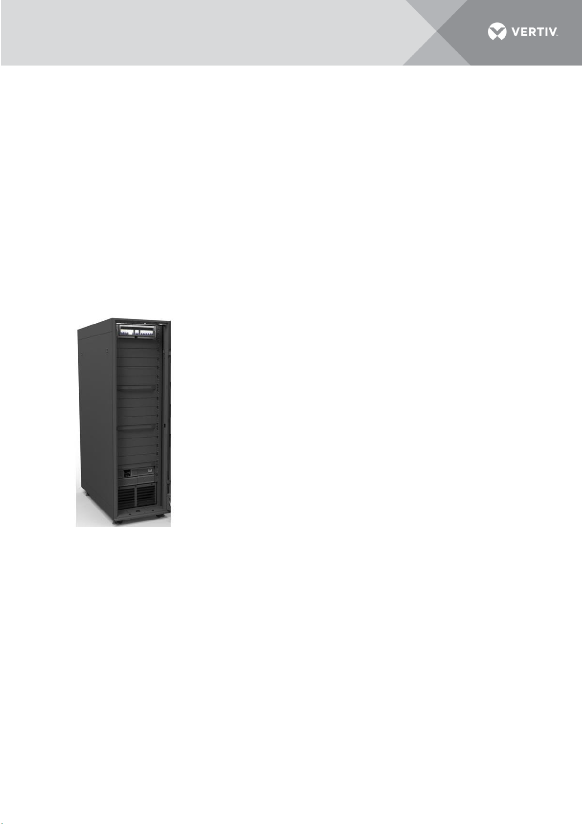
Primary technical details of the unit shown in Figure 1-1 are mentioned below:
• The unit can be installed inside the rack
• The airflow rate can be modulated based on site conditions
• The output cooling capacity modulates as per the cooling load demands
at site
• Operates on R410A refrigerant
• Quick installation and deployment being of a modular construction
• Less work and cost for installation compared to other air conditioners
• White space-saving owing to a relatively small-footprint and mounted
inside the rack utilizing lesser rack unit space
• With the unit installed inside the rack, the hot air from the rear side of the
rack is drawn inside the unit and cold conditioned air is discharged from the
front-side of the unit delivering it right in front of the server’s intake side.
• The unit can be installed on both the top and bottom of the rack inside
the rack.
• The unit also can be installed at the ceiling outside the rack.
• The direction of supply air discharged from the front side of the unit can
be changed by adjusting the grilles, up or down.
• The cooling capacity is modulated automatically by the built-in control
system and can range from 25% to 100%, about 0.9 kW to 3.5 kW. This makes
the unit best-suited for part-loads or dynamic cooling loads.
• The unit is built-in with high efficiency and reliable components which include the compressor,
electronic expansion valve, EC-fan and an advanced controller specifically designed by Vertiv for
this unit.
• Utilizes EC-fan technology for the evaporator fan which saves energy by varying the airflow rate
exactly as per the requirement.
• The condensing unit is equipped with a variable speed condenser fan with a speed variation
ranging from 30% to 100% of the entire operating range.
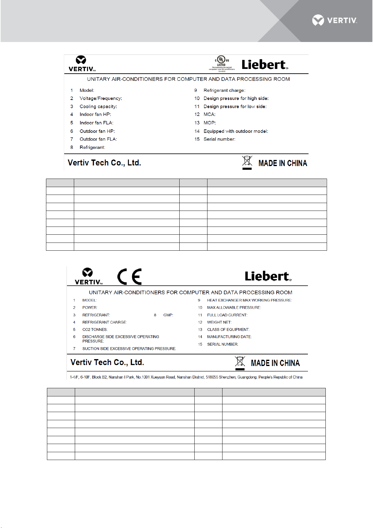
• Refer to Figure 1-2 for the nameplate description of the VRC2 Series Rack Cooler model:
Figure 1-1 Mounting
Location of the
Indoor Unit
Page 14
3
Vertiv I VRC Split System I User Manual
UL Model:
Position
Description
Position
Description
1
Unit defined by 6 digits
9
Refrigerant charge of the indoor unit
2
Supply Power
10
Discharge Side Excessive Operating Pressure
3
Cooling capacity
11
Suction Side Excessive Operating Pressure
4
Indoor fan power in total
12
Minimum Circuit Amps
5
Indoor fan full load current
13
Maximum Overcurrent Protection
6
Outdoor fan power
14
Equipped with outdoor model
7
Outdoor fan full load current
15
Serial Number
8
Refrigerant Category
CE Model:
Position
Description
Position
Description
1
Unit defined by 6 digits
9
Heat Exchange Max Working Pressure
2
Supply Power
10
Max Allowable Pressure of the Unit
3
Refrigerant Category
11
Full load Current
4
Refrigerant charge of the unit
12
Net weight
5
CO2 Tonnes
13
Class of Equipment
6
Discharge Side Excessive Operating Pressure
14
Manufacturing Date
7
Suction Side Excessive Operating Pressure
15
Serial Number
8
Global Warming Potential
Figure 1-2 Product Nameplate and Model Description
Page 15
4
Vertiv I VRC Split System I User Manual
1.2 Model Description
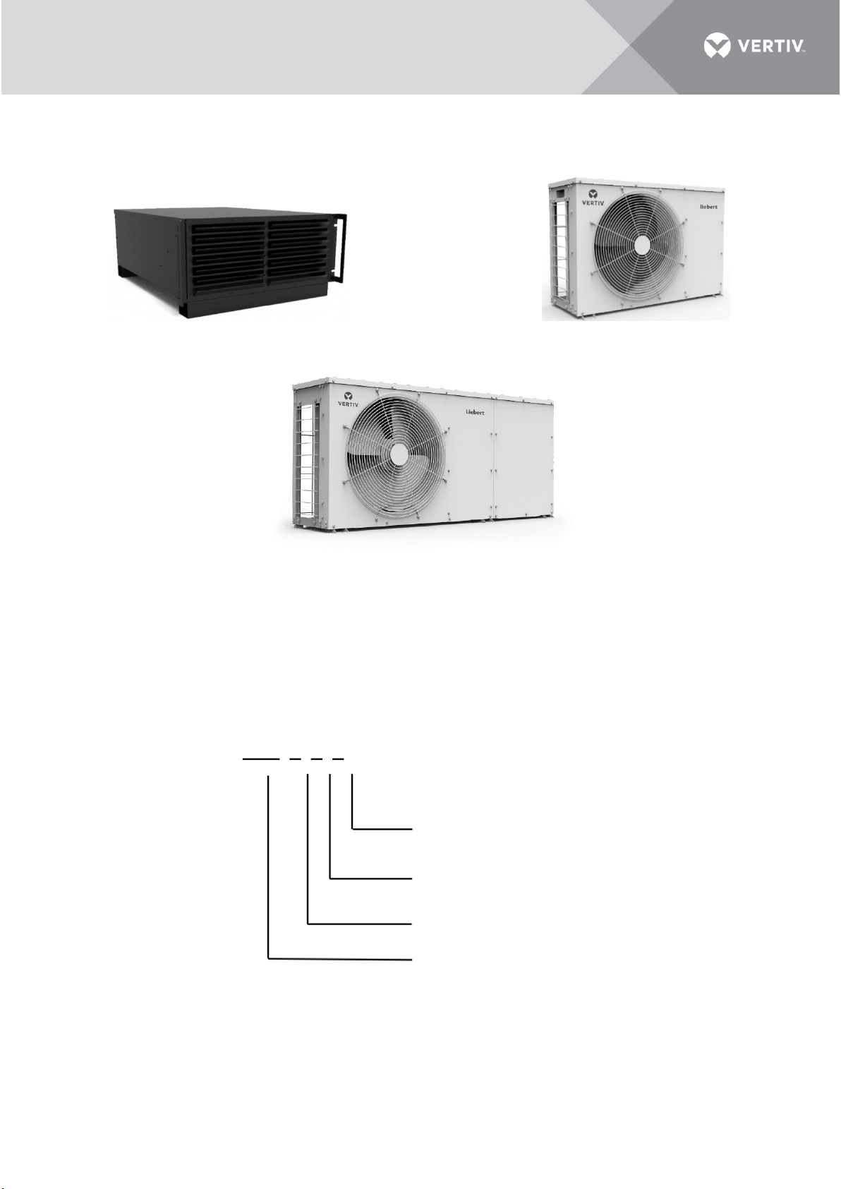
The physical appearance of air conditioner is shown in Figure 1-3.
Indoor unit Standard condensing unit
Low ambient condensing unit
Figure 1-3 Appearance of the Air Conditioner Units
The indoor unit is installed in the rack or at the ceiling. The condensing unit is mounted external to the
rack, preferably outside in an exposed environment.
1.3 Model Nomenclature
The nomenclature of the units is shown in Figure 1-4.
Figure 1-4 Nomenclature
0 = 120 V, 1 Ph, 60 Hz
1 = 208/230 V, 1 Ph, 60 Hz
2 = 230V, 1 Ph, 50/60 Hz
0 = Standard Unit
5 = Low Ambient Unit
2 = Split System Indoor Unit
3 = Split System Condensing Unit
VRC=Vertiv Rack Cooler
VRC 2 0 0
Page 16
5
Vertiv I VRC Split System I User Manual
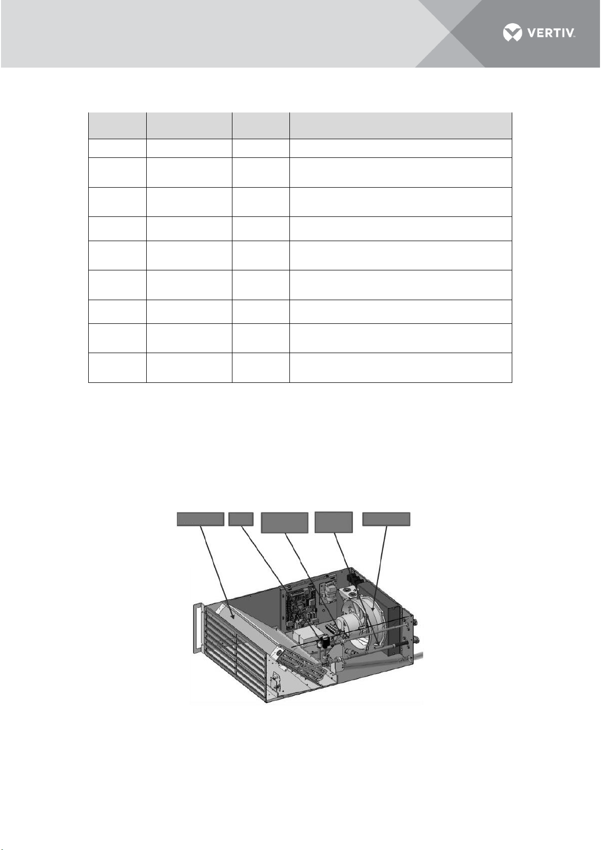
Table 1-1 mentions the description of the indoor and condensing units as per the nomenclature.
Table 1-1 Model Coding Description
Model
Power Supply
Part Code
Description
VRC200
120 V, 60 Hz
01304032
Indoor unit, 3.5 kW, 120 V
VRC300
208/230 V, 60 Hz
01304036
Condensing unit, 3.5 kW, 208/230 V for compressor
and 120 V for condensing fan
VRC350
208/230 V, 60 Hz
01304536
Low ambient condensing unit, 3.5 kW, 208/230 V for
compressor and 120 V for condensing fan
VRC201
208/230 V, 60 Hz
01304034
Indoor unit, 3.5 kW, 208/230 V
VRC301
208/230 V, 60Hz
01304035
Condensing unit, 3.5 kW, 208/230 V for compressor
208/230 V for condensing fan
VRC351
208/230 V, 60 Hz
01304537
Low ambient condensing unit, 3.5 kW, 208/230 V for
compressor 208/230 V for condensing fan
VRC202
230 V, 50/60 Hz
01304534
Indoor unit, 3.5 kW, 230 V
VRC302
230 V, 50/60 Hz
01304535
Condensing unit, 3.5 kW, 230 V for compressor 230 V
for condensing fan
VRC352
230 V, 50/60 Hz
01304538
Low ambient condensing unit, 3.5 kW, 230 V for
compressor 230 V for condensing fan
1.4 Components
The major components of the unit include the evaporator coil, condensate drain tray, evaporator EC
fan, electronic expansion valve (EEV), inverter rotary compressor, condenser coil and condenser fan.
1.4.1 Indoor Unit
The components of the indoor unit are depicted in Figure 1-5.
Figure 1-5 Indoor Unit
Indoor fan
Suction
temp.
Pressure
transducer
EEV
Evaporator
Page 17
6
Vertiv I VRC Split System I User Manual
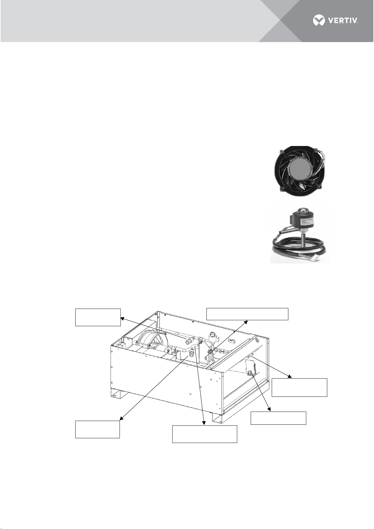
Evaporator Coil
The slant evaporator coil provides maximum surface area for heat transfer which ensures the delivered
SHR > 0.9 always. The coil is constructed from copper pipes with aluminum fins in a slit type
configuration. With low air pressure difference across the coil even at higher air flow rates, the coil
section is light and compact and has an easy access for removal and repair/replacement.
• Condensate Drain Tray
With a metallic condensate drain tray placed under the coil assembly, the entire condensate drain has
easy disposal/removal from the unit with a precise condensate outlet connection.
• Evaporator EC Fan
The indoor unit is equipped with a high-efficiency EC fan made of aluminum that
delivers high airflow rates to ensure the airflow demands are met during the
entire operational time. The EC fan has a smooth speed variation across its
operating speeds, working in synchronization with the entire system
components to deliver the precise output capacity.
• Electronic Expansion Valve
The system is incorporated with an electronic expansion valve that monitors
temperature and pressure signals simultaneously to maintain precise
adjustment of the refrigerant flow. The electronic expansion valve can ensure
even flow distribution of each end.
Sensors
Sensors provide important support for the precise control and reliable operation of indoor and outdoor
units. Figure 1-6 shows the position of the sensors in the indoor unit.
Figure 1-6 Indoor Unit Sensor Location
High pressure
transducer
Low pressure
transducer
Suction temperature
sensor
Supply air
temperature sensor
Return air temperature sensor
Water level sensor
Page 18
7
Vertiv I VRC Split System I User Manual
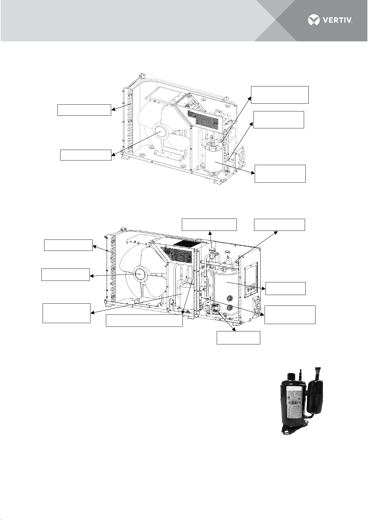
1.4.2 Condensing Unit
The components of the condensing unit are depicted in Figure 1-7 and Figure 1-8.
Figure 1-7 Standard Condensing Unit Internal Parts
Figure 1-8 Low Ambient Condensing Unit Internal Parts
• Compressor
The condensing unit is equipped with an inverter rotary compressor that works
on R410A refrigerant and which varies its cooling output capacity as per the
cooling demands. It ensures that the cooling capacity of the unit precisely
matches the cooling demand under all circumstances.
• Condenser Coil
The L-shaped condenser coil is designed for a maximum contact area. It is made
of copper with aluminum slit fin configuration.
Inverter rotary
compressor
Condenser coil
Condenser fan
Condenser fan
Condenser coil
Receiver
Inverter rotary
compressor
Discharge Hi-temp
switch
High pressure
switch
Discharge Hi-temp switch
High pressure
switch
Pressure switch
Head pressure valve
Solenoid valve
Page 19

8
Vertiv I VRC Split System I User Manual
• Condenser Fan
The condensing unit is equipped with an AC fan which varies the operating speed
as per the cooling variations of the compressor to always maintain a suitable
condensing pressure.
• Low Ambient Module
The low ambient module is equipped with a receiver, a solenoid valve and a head pressure control
valve. This module ensures that the air conditioner system can work at -34 °C (-29.2 °F).
Page 20
9
Vertiv I VRC Split System I User Manual
1.5 Technical Specifications
The detailed technical specifications which include the mechanical and the electrical details are listed
in Table 1-2.
Table 1-2 Technical Specifications
Parameters
Specification
Model
VRC200
VRC201
VRC202
VRC300
VRC301
VRC302
VRC350
VRC351
VRC352
Certification
UL 1995
(CSA C22.2 NO.236-11)
CE
(EN 60335-1;
EN 60335-2-40;
EN 55014-1;
EN 55014-2;
EN 61000-3-2;
EN 61000-3-3;
EN 50581)
UL 1995
(CSA C22.2 NO.236-11)
CE
(EN 60335-1;
EN 60335-2-40;
EN 55014-1;
EN 55014-2;
EN 61000-3-2;
EN 61000-3-3;
EN 50581)
UL 1995
(CSA C22.2 NO.236-11)
CE
(EN 60335-1;
EN 60335-240;
EN 55014-1;
EN 55014-2;
EN 61000-3-2;
EN 61000-3-3;
EN 50581)
Cooling
Capacity, kW
3.5
/
Air Volume,
m3/h (CFM)
750 (441)
/
Max Power
Input, kW
0.21
1.12
1.12
Input Voltage,
Vac
L1+L2+G,
120 Vac
L1+L2+G,
208/230 Vac
L+N+PE,
230 Vac
L1+L2+G,
208/230 Vac
L+N+PE,
230 Vac
L1+L2+L3+G,
208/230 Vac
L+N+PE,
230 Vac
Full Load
Amperage, A
2.1
1.7
1.5
7.2
7.2
6.5
7.2
7.2
6.5
Condenser FanFull Load
Amperage, A
/
0.87
0.37
0.37
0.87
0.37
0.37
Liquid Line
Solenoid Valve Full Load
Amperage, A
/
0.13
0.08
0.08
Dimensions
(W×D×H, mm
(in.))
442×602×264
(17.40×23.70×10.39)
786×282×527
(30.94×11.10×20.75)
1158×282×527
(45.60×11.10×20.75)
Frequency, Hz
60
60
50/60
60
60
50/60
60
60
50/60
Color
EG7021 (Black)
G103 (White)
IP Code
/
IPX4 (IEC 60529)
IPX4 (IEC 60529)
Net Weight, kg
(lbs.)
23 (50)
44 (97)
68 (150)
Gross Weight,
kg (lbs.)
51 (112)
70 (154)
85 (187)
Noise Level
(tested within
the rack)
<60 dB(A)
<55 dB(A)
<55 dB(A)
Operation
Temperature
range, °C (°F)
18 (64.4) to 40 (104)
-15 (5) to 45 (113)
-34 (-29.2) to 45 (113)
NOTE:
• The capacity value is measured under the conditions of indoor temperature dry bulb/wet bulb 35 °C
(95 °F), 20.6 °C (69 °F) and outdoor temperature 35 °C (95 °F).
• At the same working conditions, the low-temperature outdoor unit has a reduced capacity compared
with the standard outdoor unit.
• There are two control methods, supply control and return control. The return control mode is suggested
to be set in an open environment, while the supply control mode is suggested to be set in an enclosed
rack.
Page 21
10
Vertiv I VRC Split System I User Manual
• Supply air temperature set point varies between 12.8 °C (64.4 °F) and 23 °C (73.4 °F ). The recommended
supply air temperature set point is 21 °C (69.8 °F ).
• When the VRC unit is used in a closed rack, the heat load should be evenly placed in rack and unused rack
position should be covered with blanking plates.
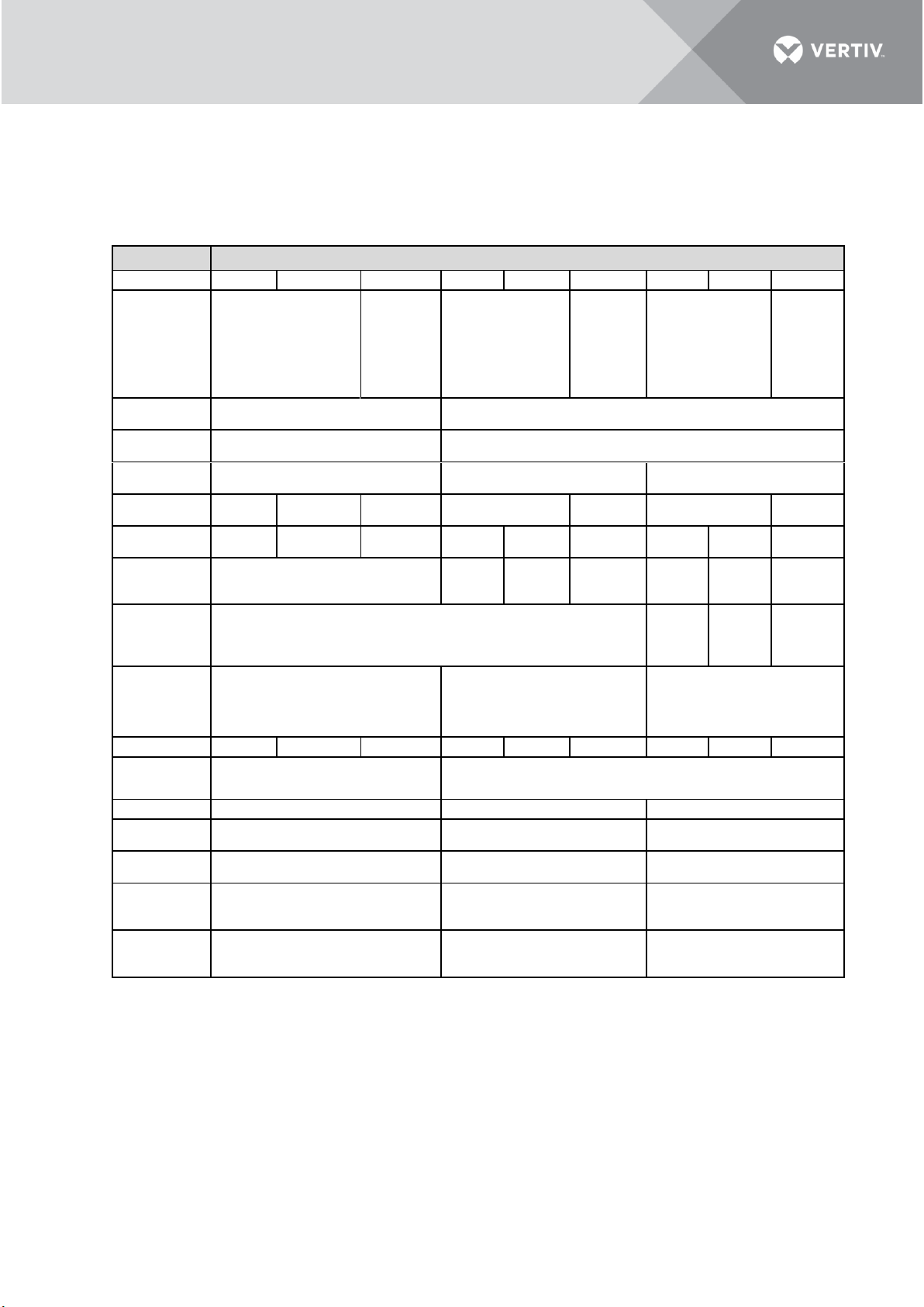
The maximum capacities vary with temperatures, as shown below.
Standard Condensing Unit
Maximum Capacity, kW
Condenser Air Temperature
29.4 °C
(85 °F )
35 °C
(95 °F )
40 °C
(104 °F )
Evaporator Air Temperature to IT
Devices
19 °C
(66 °F )
3.7
3.6
3.6
21 °C
(70 °F )
3.9
3.8
3.8
23 °C
(73 °F )
3.9
3.8
3.8
Standard Condensing Unit
Maximum Capacity, kW
Condenser Air Temperature
29.4 °C
(85 °F )
35 °C
(95 °F )
40 °C
(104 °F )
Evaporator Air Temperature to
Cooling Module
29.4 °C
(85 °F )
3.4
3.3
2.8
35 °C
(95 °F )
3.8
3.7
3.2
40 °C
(104 °F )
4.0
3.9
3.4
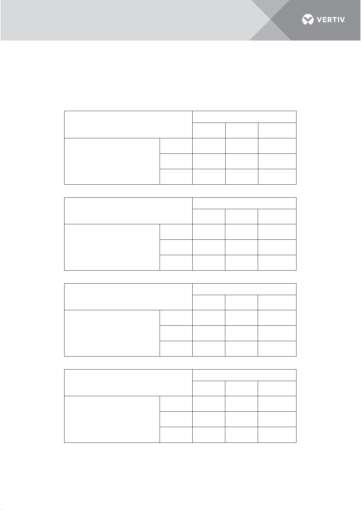
Low Ambient Condensing Unit
Maximum Capacity, kW
Condenser Air Temperature
29.4 °C
(85 °F )
35 °C
(95 °F )
40 °C
(104 °F )
Evaporator Air Temperature to IT
Devices
19 °C
(66 °F )
3.2
3.1
3.1
21 °C
(70 °F )
3.4
3.4
3.4
23 °C
(73 °F )
3.5
3.4
3.4
Low Ambient Condensing Unit
Maximum Capacity, kW
Condenser Air Temperature
29.4 °C
(85 °F )
35 °C
(95 °F )
40 °C
(104 °F )
Evaporator Air Temperature to
Cooling Module
29.4 °C
(85 °F )
3.1
3.0
2.5
35 °C
(95 °F )
3.5
3.4
2.9
40 °C
(104 °F )
3.6
3.5
3.0
Page 22
11
Vertiv I VRC Split System I User Manual
The minimum capacities vary with temperatures, as shown below.
Standard Condensing Unit
Minimum Capacity, kW
Condenser Air Temperature
29.4 °C
(85 °F )
35 °C
(95 °F )
40 °C
(104 °F )
Evaporator Air Temperature to IT
Devices
19 °C
(66 °F )
0.92
0.90
0.88
21 °C
(70 °F )
0.94
0.92
0.90
23 °C
(73 °F )
0.96
0.94
0.92
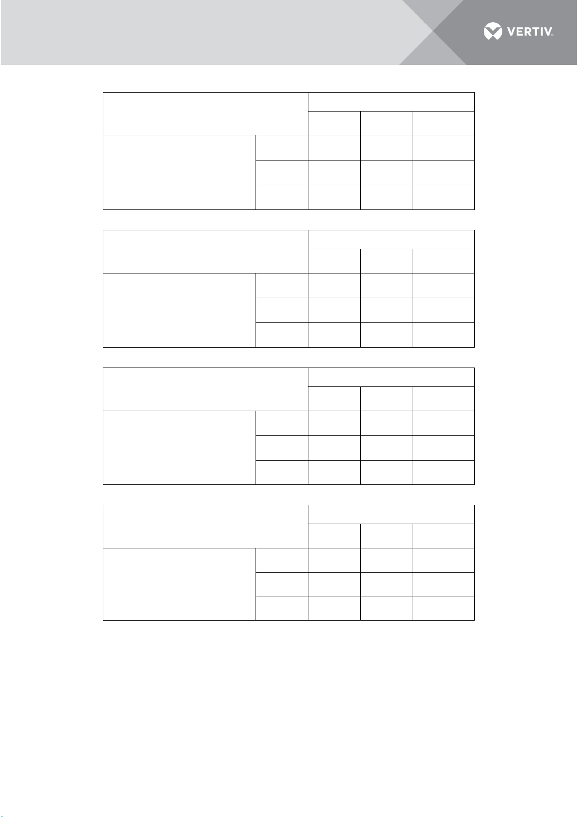
Standard Condensing Unit
Minimum Capacity, kW
Condenser Air Temperature
29.4 °C
(85 °F )
35 °C
(95 °F )
40 °C
(104 °F )
Evaporator Air Temperature to
Cooling Module
29.4 °C
(85 °F )
0.92
0.90
0.88
35 °C
(95 °F )
0.94
0.92
0.90
40 °C
(104 °F )
0.96
0.94
0.92
Low Ambient Condensing Unit
Minimum Capacity, kW
Condenser Air Temperature
29.4 °C
(85 °F )
35 °C
(95 °F )
40 °C
(104 °F )
Evaporator Air Temperature to IT
Devices
19 °C
(66 °F )
0.91
0.89
0.87
21° C
(70 °F )
0.93
0.91
0.89
23 °C
(73°F)
0.95
0.93
0.91
Low Ambient Condensing Unit
Minimum Capacity, kW
Condenser Air Temperature
29.4 °C
(85 °F )
35 °C
(95 °F )
40 °C
(104 °F )
Evaporator Air Temperature to
Cooling Module
29.4 °C
(85 °F )
0.91
0.89
0.87
35 °C
(95 °F )
0.93
0.91
0.89
40 °C
(104 °F )
0.95
0.93
0.91
Page 23

12
Vertiv I VRC Split System I User Manual
PART II
INSTALLATION
Page 24
13
Vertiv I VRC Split System I User Manual
2 Pre-Installation
The air conditioner is an equipment and requires installation works. The preliminary preparation is
very important. This chapter details the pre-installation, including how to prepare the installation
environment and space and reserve the maintenance space, the air conditioner running and storage
environment requirement, and how to unpack and inspect. Please read this chapter carefully before
installation.
WARNING! Risk of improper wiring, piping, moving, lifting and handling. Can cause equipment
damage, serious injury or death. Installation and service of this equipment should be done only
by qualified personnel who have been specially-trained in the installation of air-conditioning
equipment and who are wearing appropriate, OSHA-approved PPE.
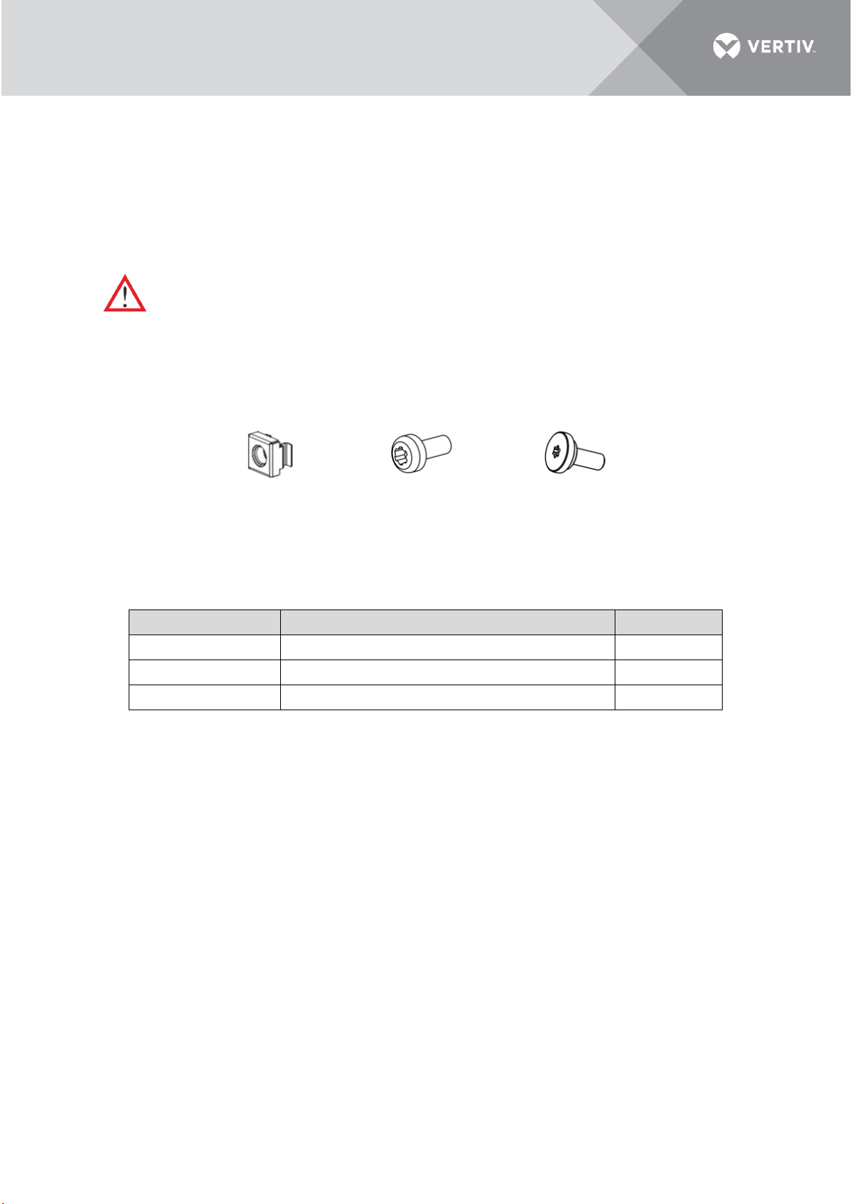
2.1 Fittings
The fittings are shown in Figure 2-1.
Figure 2-1 Fittings
The usage of fittings is shown in Table 2-1. They are included in the package.
Table 2-1 Fittings Instruction
2.2 Self-Prepared Materials
The cables routed from the room to the unit and the circuit breakers must be prepared at the customer
site or are to be obtained by the customer; the specifications for the same are given in the Table 2-2.
Fitting Utility
Usage
Quantity
M6 cage nut
Used with M6 pan-head screws for tightening pillars
6
M6 Pan-head screw
Used to install the VRC 20X unit
6
M5 center screw
Used to fasten the L-shape mounting rails
10
M6 Cage Nut
M6 Pan-head Screw
M5 Center Screw
Page 25
14
Vertiv I VRC Split System I User Manual
Table 2-2 Self-Prepared Materials
Parts
Specifications
External circuit breaker 1
Please refer to FLA (Full Load Amperage) of
indoor unit in Table 1-2
External circuit breaker 2
Please refer to FLA of condensing unit in
Table 1-2
Input power supply cables for indoor unit
Please refer to FLA of indoor unit in Table 1-
2
Input power supply cables for condensing unit
Please refer to FLA of condensing unit in
Table 1-2
Cables for condenser fan
Please refer to FLA of condenser fan in Table
1-2
Cables for liquid line solenoid valve (only used in VRC350,
VRC351 and VRC352)
Please refer to FLA of liquid line solenoid
valve in Table 1-2
Liquid copper pipe
Please refer to pipe connection of unit
Gas copper pipe
Please refer to pipe connection of unit
Communication line between indoor and condensing unit
Communication line with RJ45 ports
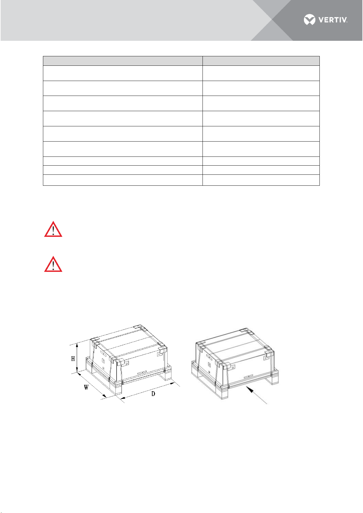
2.3 Transportation and Movement
WARNING! The components of the unit are comparatively large and heavy. Therefore, there may
be a risk when the containment collapses. The collapse may result in physical injury, fatality and
damage to the equipment.
CAUTION: Risk of contact with sharp edges, splinters, and exposed fasteners. Can cause injury.
Only properly trained and qualified personnel wearing appropriate, OSHA-approved PPE should
attempt to move, lift, remove packaging from or prepare the unit for installation.
The unit consists of an indoor unit and an outdoor unit. Both of them are comparatively heavy
equipment and need to be moved by hand pallet truck or electrical forklift to the vicinity of the predecided location to be installed. Table 2-3, Figure 2-2 and Figure 2-3 show the dimensions of the unit’s
component with the package.
Figure 2-2 Package Dimensions – Indoor Unit
Forklift direction
Page 26
15
Vertiv I VRC Split System I User Manual
Figure 2-3 Package Dimensions – Condensing Unit
The unit with packing dimensions and weights are listed in Table 2-3:
Table 2-3 Packaging Dimensions
Component
Packaging
Range of Dimensions
(Unit: mm (in.))
Weight with Package
(Unit: kg (lbs.))
H W D
Unit with
package
VRC200
VRC201
VRC202
Wooden
pallet with
cardboard
box
460
(18.11)
760
(29.92)
830
(32.68)
51
(112)
VRC300
VRC301
VRC302
750
(29.53)
480
(18.90)
970
(38.19)
70
(154)
VRC350
VRC351
VRC352
755
(29.72)
480
(18.90)
1350
(53.20)
85
(187)
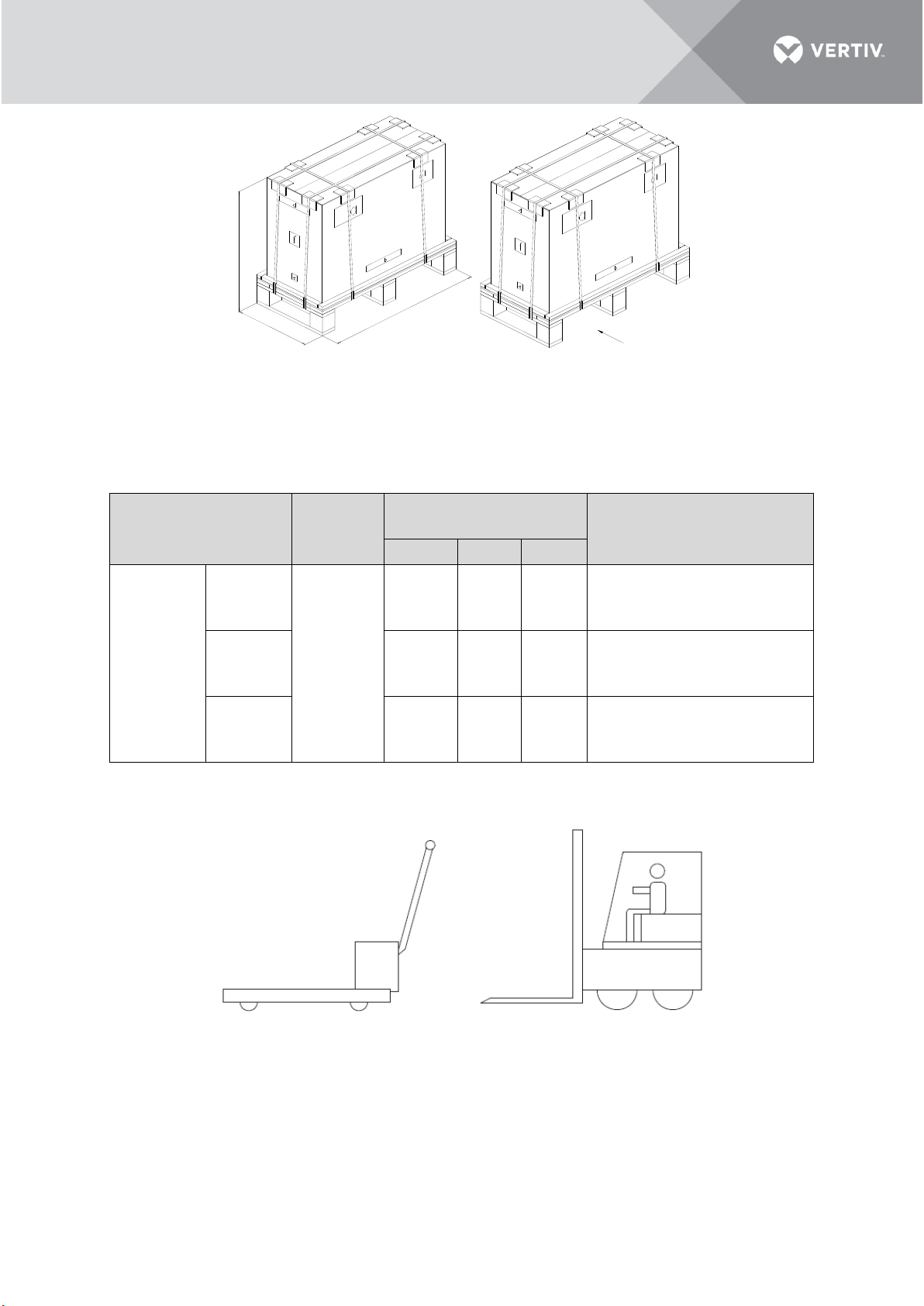
Figure 2-4 depicts the schematic diagram of a hand pallet truck and an electric forklift.
Figure 2-4 Hand Pallet Truck and Electric Forklift
If a hand pallet truck or an electric forklift truck is used, the tines of the hand pallet or electric forklift
must be aligned with the center of gravity to prevent the package from toppling or falling over as
depicted in Figure 2-5.
H
W
D
Forklift Direction
Forklift direction
Electrical forklift
Hand pallet truck
Page 27

16
Vertiv I VRC Split System I User Manual
Figure 2-5 Forklift Direction
While moving the package, the obliquity must be maintained at an angle of 90° ± 10°. As shown in
Figure 2-6, the 90° ± 10° obliquity is suitable to move the rack to the vicinity of the desired location.
Figure 2-6 Carrying Obliquity
NOTE:
• Ensure that the equipment stands upright.
• While using the forklift or the hand pallet truck, ensure that the fork arms (if adjustable and flexible)
open to the greatest extent. This is done so that the fork arms can be placed under the pallet of the
equipment in a precise manner.
• Ensure that the length of the fork arms match with that of the equipment.
2.4 Unpacking
Following are the steps and procedures that are to be observed during the unpacking process:
2.4.1 Unpacking of Indoor Unit
• The unpacking of the indoor unit from the packing materials is shown in Figure 2-7. Move the
equipment of the assembled package to an open, firm leveled ground in the vicinity of the
predetermined installation site.
• Cut off the packing strip on the package paper box using a utility knife followed by removing the
package paper box of the unit.
• Remove the packing materials, including paper cover, support cardboard, paper box, cushion and
paper corner in a specific order as mentioned from the top side of the unit.
• Remove the unit from the wooden pallet.
Forklift Direction
Forklift direction
Page 28

17
Vertiv I VRC Split System I User Manual
The accessory list of the indoor unit is shown in Table 2-4.
Figure 2-7 Unpacking Indoor Unit
Table 2-4 VRC2 Series Accessories
No.
Item
Quantity
1
Drainage Kit
Condensate Pump and Pump Bracket
1
2
Condensate Water Pipe (7.5 m /24.6 ft.)
1
3
Drain fitting
1
4
Display kit
Display and Display Magnetic Box
1 5 10 m (32.8 ft.) Cable of Display
1 6 0.5 m (1.6 ft.) Cable of Display
1
7
SIC Card Kit
1
8
L-shape Mounting Rail Kit
2 9 Cage Nuts (M6)
6
10
Pan-Head Screws M6x12 (Torx T30)
6
11
Center Screws M5x12 (Torx T20)
10
12
USB Converter Cable
1
13
Cable Ties 100x2,5
10
14
User Manual
1
15
VRC Cooling Unit
1
2.4.2 Unpacking of Condensing Unit
• The unpacking of the condensing unit from the packing materials is shown in Figure 2-8.
• Move the equipment of the assembled package to an open, firm leveled ground in the vicinity of
the installation site.
• Cut off the packing strip on the package paper box using a utility knife followed by removing the
package paper box of the unit.
• Remove the packing materials, including paper cover, support cardboard, paper box, cushion and
Display and display
magnetic box
(4)
VRC cooling unit
(15)
SIC card kit
(7)
Drain fitting
(3)
Condensate pump and
pump bracket
(1)
Condensate water pipe
(2)
EPE
L-shape mounting rail kit
(8)
Page 29

18
Vertiv I VRC Split System I User Manual
paper corner in a specific order as mentioned from the top side of the unit.
• Remove the unit from the wooden pallet.
Standard condensing unit Low ambient condensing unit
Figure 2-8 Unpacking Condensing Unit
NOTE: Packing materials of the unit are recyclable. Retain the packing materials for further use or dispose
them appropriately as per the protocols and local regulations.
The accessory list of the condensing unit is shown in Table 2-5.
Table 2-5 VRC3 Series Accessories
Sr No.
Item
Quantity
Model
1 Side Panel
2
VRC300
VRC301
VRC302
2 Front Panel
1
3 Screws (M4x10)
10
2.5 Equipment Installation Room Requirements
The requirements are as follows:
• To ensure the normal operation of environmental control system, the rack should be free from air
leakages that de-stabilize the temperature gradient and also could lead into moisture occurrence.
• The rack should have appropriate thermal separation.
• The condensing air entering the equipment room should be reduced to a minimum as the entry
of condensing air may increase the load of the system. It is recommended that the leakage rate
of condensing air be kept below 5% of the total internal airflow.
• All the doors and windows should be closed properly to avoid any air infiltration from outside into
the room.
NOTE: Avoid locating the indoor unit in concave or narrow areas which can affect the airflow. It is prohibited
to use the cooling unit in an unconducive condensing environment.
Page 30

19
Vertiv I VRC Split System I User Manual
2.6 Environment
Following are the requirements that need to be observed from the environment point of view for site
preparation of the unit:
• CAUTION: Keep the unit in a place far away from sparks or any heat source.
• CAUTION: Emission of erosive gases and organic solvents should not be near the unit.
2.6.1 Operating Environment
The operation environment requirements are mentioned in Table 2-6.
Table 2-6 Operating Environment
Item
Requirements
Installation position
The maximal equivalent length of piping between the indoor unit and
condensing unit [1]: 30 m (98.43 ft.)
Vertical distance ΔH [2]: -5 m (-16.40 ft.) ≤ ΔH ≤15 m (49.21 ft.)
Ambient temperature
Indoor: 18 °C to 40 °C (64.4 °F to 104 °F)
Standard condensing: -15 °C to 45 °C (5 °F to 113 °F)
Low ambient condensing unit: -34 °C to 45 °C (-29.2 °F to 113 °F)
Ambient humidity
17% to 60%
Protection level
Condensing unit: IPX4 (IEC 60529)
Altitude
< 1000 m (3280.84 ft.). For every 1000m increase in elevation, the evaporation
temperature drops by 0.5 °C (0.9 °F ) the net cooling capacity drops by 7%
NOTE:
[1] For the equivalent length of parts, refer to Table 3-7
[2] The value is positive if the condensing unit is installed above the indoor unit; negative if the indoor
unit is installed above the condensing unit
2.6.2 Storage Environment
The storage environment requirements are mentioned in Table 2-7.
Table 2-7 Storage Environment
Item
Requirements
Storage environment
Clean (without dust)
Ambient humidity
< 95% RH @40 °C (104 °F)
Ambient temperature
-40 °C to 70 °C (-40 °F to 158 °F)
Storage time
The total shipment and storage time should not exceed 6 months. Otherwise,
the performance needs to be re-calibrated
2.7 Installation Space Requirements
The indoor unit is a specifically engineered air conditioning unit. It is recommended to install the
indoor unit inside the rack at the lowest rack unit space, as shown in the installation section.
Page 31

20
Vertiv I VRC Split System I User Manual
2.8 Clearance Space
2.8.1 Indoor Unit
To facilitate ease of installation and maintenance, enough space must be provisioned at site. When the
indoor unit is installed in room, the distance from the front and other sides of the unit to the wall or
other obstacles must be greater than 1000 mm (30.00 in.) and 600 mm (18.00 in.) respectively, as
shown in Figure 2-9. When the indoor unit is installed in the rack, the distance from the front and rear
sides of the rack to the wall or other obstacles must be greater than 1000 mm (30.00 in.) and 600 mm
(18.00 in.) respectively.
Figure 2-9 Minimum Distance for Pull-out during Maintenance (Top View)
2.8.2 Condensing Unit
For standard condensing unit, it is not necessary to install air deflector when used in indoor
environment or in outdoor environment that are always greater than 0°C (32°F), see Figure 2-10. For
units without air deflector, the recommended clearance space is shown in Figure 2-11. Otherwise, it
is necessary to install air deflector when used in outdoor environment below 0°C (32°F), and the
necessary clearance space is shown in Figure 2-12. If there is no wall to meet the installation clearance,
it is recommended to use the low ambient condensing unit. Besides, it is necessary to use the low
ambient condensing unit when outdoor temperature is below -15°C (5°F).
Figure 2-10 Standard Condensing Unit Without Air Deflector for Indoor Use
600mm
[18'']
600mm
[18'']
600mm
[18'']
1000mm
Indoor
Indoor
Page 32

21
Vertiv I VRC Split System I User Manual
Figure 2-11 Clearance space required for standard condensing unit without air deflector for outdoor use
Figure 2-12 Clearance Space Required for Standard Condensing Unit With Air Deflector
Front
Outdoor
Wall
Standard outdoor unit
Back
Standard outdoor unit + air deflector
Wall
Back
Front
Necessary clearance when installing air deflector = 200 mm (7.9 in.)
≥450 mm (17.7 in.)
≥450 mm (17.7 in.)
≥450 mm (17.7 in.)
≥450 mm (17.7 in.)
≥450 mm (17.7 in.)
Outdoor
(Above 0°C (32°F) all year round)
Page 33

22
Vertiv I VRC Split System I User Manual
For low ambient condensing unit, the air deflector does not need to be installed. The distance from
the wall should be large enough to be maintained and the minimum distance from the front side
(supply air side) of the condensing unit should be 450 mm (17.72 in.) from any wall, obstacles or
adjacent devices. It is a must to provide these clearance distances as shown in Figure 2-13 to ensure
appropriate airflow across the condensing unit.
Figure 2-13 Recommended Clearance Space Required for Low Ambient Condensing Unit
2.9 Weight Bearing Capacity
The cooling unit will be installed inside the rack because the concentrated floor loading of the rack will
increase. Therefore, the weight bearing capacity of the floor of the computer room must be taken into
consideration.
2.10 Inspection
• The unit is pre-charged. Check that there is no refrigerant and oil leaks.
• Check the system fittings and its components against the packing list to ensure that everything is
in its designated position and the entire product assembly is intact.
• If any parts or components are missing or damaged, immediately report to the carrier. If hidden
damages are observed, then contact the local offices of that carrier as well as Vertiv Group Corp.
at the earliest.
Wall
Back
Front
Wall
Back
Front
≥450 mm (17.7 in.)
≥450 mm (17.7 in.)
Outdoor
Page 34

23
Vertiv I VRC Split System I User Manual
3 Mechanical Installation
Proper installation is essential to achieve the intended design performance of the equipment and to
maximize its service life. This chapter describes the mechanical installation of cooling system, including
installation notes, system installation layout, end installation, unit piping installation, installation
finishing work and installation check. This section should be used in conjunction with current
mechanical and electrical installation regulations.
3.1 Installation Notes
NOTE:
• The indoor unit needs to be installed inside the rack or in room.
• Before installation, make sure that the installation environment meets the requirements and there must
be sufficient provision for connecting the condensate drain line to the drain point.
• Follow the design drawings strictly when installing the equipment and reserve the space for maintenance.
The manufacturer’s engineering dimensions drawings can serve as a reference.
• Two persons are required for installation.
• Torx bits T20 and T30 are needed during installation, as shown in Figure 3-1.
Figure 3-1 Torx Bits
3.2 System Installation Layout
The overall layout of the unit which comprises both the indoor unit and the condensing unit is depicted
in Figure 3-2, Figure 3-3 and Figure 3-4.
Figure 3-2 Indoor Unit
Page 35

24
Vertiv I VRC Split System I User Manual
Figure 3-3 Standard Condensing Unit
Figure 3-4 Low Ambient Condensing Unit
The dimensions of indoor unit and condensing unit are listed in Table 3-1:
Table 3-1 Dimensions of Indoor and Condensing Unit
Component
Range of Dimensions (Unit: mm (in.))
H W D
Indoor Unit
VRC200
VRC201
VRC202
264
(10.39)
442
(17.40)
602
(23.70)
Condensing Unit
VRC300
VRC301
VRC302
527
(20.75)
786
(30.94)
282
(11.10)
VRC350
VRC351
VRC352
527
(20.75)
1158
(45.60)
282
(11.10)
Each standard condensing unit (VRC300, VRC301, VRC302) has a set of air deflector. The dimension of
the air deflector is shown in the Table 3-2.
Table 3-2 Dimension of Air Deflector
Component
Range of Dimensions (Unit: mm (in.))
h w d
Standard Condensing
Unit
VRC300
VRC301
VRC302
500
(19.68)
563
(22.17)
233
(9.17)
Page 36

25
Vertiv I VRC Split System I User Manual
3.3 Installing the Unit
3.3.1 Installing the Indoor Unit Inside the Rack
A front view with dimensions is shown in Figure 3-5 and Figure 3-6, which would help mount the unit
inside the rack.
Figure 3-5 Indoor Unit Dimensions
Figure 3-6 Front View of Indoor Unit
The detailed dimensions of the indoor unit with their weights are mentioned in Table 3-3.
Table 3-3 Dimensions of Cooling Unit
Model
Dimensions (W × D × H, mm (inch))
Net Weight (kg. (lbs))
Cooling unit
442 × 602 × 264
(17.40×23.70×10.39)
23.0 (50.7)
1. Mounting the L-shaped rails in the rack
Each of the two L-shape rails is comprised of two parts, a long front rail and a slotted rear bracket, as
shown in Figure 3-7. There are left and right VRC rails. The flanges of each of the front rails should be
on the bottom and pointing toward the center of the rack. Slip the slots in the rear rail bracket over
the pressed studs in the front rail part. Loosely fasten with nuts. Fasten the ends of the front rails and
rear brackets to the uprights using center screws M5x12 T20. Torque=4.0 Nm (2.95 ft.-lb.). Once in
place, tighten the nuts on the front rail part studs. Torque = 5.6 Nm (4.13 ft.-lb.).
W
H
D
491.6 mm
[19.35'']
465.0 mm
[18.31'']
442.0 mm
[17.40'']
263.5 mm
[10.37'']
219.0 mm
[8.62'']
146.0 mm
[5.75'']
Φ7.2 mm
[0.28'']
Page 37

26
Vertiv I VRC Split System I User Manual
Figure 3-7 L-Shape Rails Installation
2. Inserting the indoor unit into the rack
Insert the indoor unit into the front of the rack until its front brackets are against the rack’s uprights.
3. Fastening the indoor unit
Fasten the indoor unit front brackets to both front uprights using four M6 cage nuts and M6x12 T30
screws (5.6 Nm/4.13 ft.-lb. torque), as shown in Figure 3-8.
Figure 3-8 Indoor Unit Installation
NOTE:
• Make sure the indoor unit is installed horizontally, otherwise high-water level alarms may be triggered
incorrectly.
• For installation in a 2-post rack, please purchase accessory 2POSTRMKITVRC. Installation instructions
are included with this rail kit.
3.3.2 Installing the Condensing Unit
The physical appearance of the condensing unit is shown in Figure 3-3 and Figure 3-4. The top view of
the standard condensing unit is shown in Figure 3-9 and the low ambient condensing unit is shown in
Figure 3-10.
Left VertivTM VRC
front rail
Left VertivTM VRC
slotted rear bracket
Cross section of VertivTM VRC-S shown
for Illustrative purposes.
Slotted rear
bracket
Slotted rear
bracket
Front rail part
Front rail part
Page 38

27
Vertiv I VRC Split System I User Manual
Figure 3-9 Standard Condensing Unit Top View
Figure 3-10 Low Ambient Condensing Unit Top View
Table 3-4 Condensing Unit Dimensions
Model
Dimensions (W × D × H, mm
(in.))
Net Weight (kg (lbs.))
VRC300
VRC301
VRC302
786×282×527
(30.94×11.10×20.75)
44.0 (97.0)
VRC350
VRC351
VRC352
1158×282×527
(45.60×11.10×20.75)
68.0 (149.9)
The condensing unit must be installed vertically. The condensing unit can either be installed higher
than the indoor unit or lower than the indoor unit. Figure 3-11 shows the scenario where the
condensing unit is installed higher than the indoor unit. When installing the condensing unit 7.5m
higher than the indoor unit, a trap should be installed on the discharge pipe. This trap will retain
refrigerant oil in the off cycle of the compressor. When the compressor starts, oil in the trap will be
carried up and return to the compressor immediately.
829mm
[32.6'']
696mm
[27.4'']
298mm
[11.7'']
530mm
[20.9'']
R5mm
[R0.2'']
563mm
[22.2'']
1206mm
[47.5'']
1073mm
[42.2'']
316mm
[12.4'']
298mm
[11.7'']
R5mm
[R0.2'']
Page 39

28
Vertiv I VRC Split System I User Manual
Figure 3-11 Condensing Unit Installed Higher Than the Indoor Unit
Figure 3-12 shows the scenario where the condensing unit is installed lower than the indoor unit.
Figure 3-12 Condensing Unit Installed Lower Than the Indoor Unit
Outdoor unit
Liquid side pipe (no direct sunlight)
Isolation floor
Wall bushing
Trap
Rack
Indoor unit
Max
7.5m
[24.60 ft]
Sealing on inlets
Gas side pipe
Heat insulation
material
Floor
15m
[49.21ft]
Drain pipe of condensate water
(extend to outdoor to drain
condensate water)
1:200
Drain pipe of condensate water
(extend to outdoor to drain
condensate water)
1:200
Sealing on inlets
Gas side pipe
Heat insulation
material
Floor
Isolation floor
Wall bushing
Outdoor unit
Rack
Indoor unit
5m
[16.40ft]
Page 40

29
Vertiv I VRC Split System I User Manual
Table 3-5 shows the vertical distance between the indoor and the condensing unit.
Table 3-5 Vertical Distance Between Indoor Unit and Condensing Unit
Relative Position
Value
Condensing unit installed higher than indoor unit
Maximum: 15 m (49.21 ft.)
Condensing unit installed lower than indoor unit
Maximum: 5 m (16.40 ft.)
Following are the steps that need to be observed for the regular installation of the condensing unit:
1. Place the condensing unit on the base
2. Use expansion bolts to fix the condensing unit on the base.
If there are multiple condensing units, they need to be placed on top of the other. Figure 3-13 shows
how to place the condensing units.
Following points need to be taken into consideration during the installation of the condensing unit.
NOTE:
• The condensing unit must be placed appropriately in a safe place for maintenance. It should not be
installed on the bottom floor of the public site or kept in a residential area.
• It should not be kept in an environment where noise levels are considered crucial.
• Keep the condensing unit in a clean environment, free of debris, dust, and foreign matter. This is done to
avoid blocking of the heat exchanger and ensure an efficient cooling effect.
• There should be no steam, hot gas, or exhaust gas near the condensing unit.
• Preferably, keep 450 mm between the condensing unit and the wall, obstacles, or adjacent devices. For
standard condensing unit, if the condensing unit will be installed in an outdoor environment, the
recommended distance of the back side (return air side) from the wall should be 200 mm (7.87 in.). It is
a must to provide these clearance distances to ensure appropriate airflow across the condensing unit.
• Avoid keeping the condensing unit in places where snow may accumulate in the air intake side and air
outlet side.
• Preparing a base to bear the weight of the condensing unit is important where the base should be at least
50 mm (1.97 in.) higher than the ground and 50 mm (1.97 in.) wider than the condensing unit base.
• The weight is around 44 kg (97 lbs.) for standard condensing unit or 68 kg (150 lbs.) for low ambient
condensing unit. Therefore, utmost care must be taken while removing it. Any mishandling will result in
severe injury and damage to the equipment.
Page 41

30
Vertiv I VRC Split System I User Manual
Figure 3-13 Installing Multiple Condensing Units with One Above the Other
3.3.3 Installing the drain fitting to the indoor unit
Fasten the drain fitting to the drain port of the indoor unit, as shown in Figure 3-14. The drain fitting
contains a sealing block, which is used for preventing the water leaking from the drain fitting port.
Make sure the sealing block is installed tightly.
Figure 3-14 Installing the Drain Fitting
Airflow
Min. 50mm [1.97 in.]
50mm
[1.97 in.]
50mm
[1.97 in.]
Bracket
Outdoor
unit
Outdoor
unit
Airflow
4m
[13.12 ft.]
0.2m
[0.66 ft.]
Note:
1. Use 5# angle iron for bracket, when two
units are installed with one above the other.
2. Use 6.5# channel steel for bracket, when
three units are installed with one above
another.
Drain fitting
sealing block
Drain fitting
Base
Outdoor unit base
Page 42

31
Vertiv I VRC Split System I User Manual
3.3.4 Installing the Condensate Pump
NOTE: Please finish the cable connection in chapter 4 first, otherwise it will be difficult to connect the cables.
1. Divide the pump bracket into part 1 and part 2, as shown in Figure 3-15 and Figure 3-16.
Figure 3-15 Appearance of Pump Bracket
Figure 3-16 Internal Structure of Water Pump Bracket
2. Install the power cord and the L-shape pipe, as shown in Figure 3-17.
Figure 3-17 Internal Structure of Water Pump Bracket
3. Loosen the four screws in Figure 3-17 for about four turns.
4. Slide the pump bracket part 1 on L-shape mounting rail, as shown in Figure 3-18.
Figure 3-18 Installation of The Pump Kit
5. Install L-shape pipe to drain fitting, and fix it with a cable tie, as shown in Figure 3-18.
6. Tighten the four screws to fix the pump bracket part 1, as shown in Figure 3-17.
7. Tighten the two screws to install pump bracket part 2 to pump bracket part 1, as shown in Figure 3-
19.
Pump bracket
part 1
Pump bracket
part 2
Pump bracket
part 1
Screws (M5 x12)
L-shape pipe
Power cord
Drain fitting
Cable tie
Page 43

32
Vertiv I VRC Split System I User Manual
Figure 3-19 Installation of The Pump Bracket Part 2
There are one anti-Siphoning device and a condensate water pipe in indoor unit package. The antiSiphoning device is used to prevent siphonage and should be installed vertically on the pipe. The
condensate water pipe can be used to extend drainage lines.
Figure 3-20 Anti-Siphoning Device and Condensate Water Pipe
3.4 Connecting the Copper Pipes to the Unit
For standard condensing unit, if a deflector must be installed, install the air deflector first before
connecting the copper pipes, as shown in Figure 3-21. Otherwise, you can ignore the air deflector
installation steps.
Figure 3-21 Air Deflector Installation for Standard Condensing Unit
In this section, the general principles of connecting copper pipes, installation information about the
connectors and the required pipe connections will be explained in detail. Figure 3-22, Figure 3-23 and
Figure 3-24 show connectors on both the indoor and the condensing unit.
Pump bracket
part 2
Stainless steel pan
head screw * 4pcs
Front panel
*1pcs
Side panel
*2pcs
Air deflector
Page 44

33
Vertiv I VRC Split System I User Manual
General Principles
• Copper pipes with quick thread connectors must be used to connect the indoor and condensing
unit. If the pipe length exceeds the standard pipe length and a straight copper pipe is used, piping
joints must be brazed.
• Follow standard industry practices in selecting and placing pipes, evacuating the system, and
charging the system with refrigerant. The standard refrigerant of the unit is R410A. The charging
amount with low ambient condensing unit is 4.0kg (8.82 lbs), while the amount with standard
condensing unit is 1.3 kg (2.87 lbs).
• Avoid oil leakage and clogging in the system. Utmost care while considering these factors
minimizes the noise and vibration significantly.
Figure 3-22 Connectors of Indoor Unit
Figure 3-23 Connectors of Standard Condensing Unit
Figure 3-24 Connectors of Low Ambient Condensing Unit
• Use thermal insulation material to cover quick thread connectors of both indoor and condensing
Liquid pipe: 3/8''
Connector: 5/8'' -18UNF
Suction pipe: 1/2''
Connector: 3/4'' -16UNF
Drain pipe: 1/2 NPT
Liquid pipe: 3/8''
Connector: 5/8'' -18UNF
Suction pipe: 1/2''
Connector: 3/4'' -16UNF
Liquid pipe: 3/8''
Connector: 5/8'' -18UNF
Suction pipe: 1/2''
Connector: 3/4'' -16UNF
Needle valves
Page 45

34
Vertiv I VRC Split System I User Manual
units, after completing the installation and commission, as shown in Figure 3-25.
Figure 3-25 Keeping Copper Piping and Quick Thread Connector Insulated
Installation notes of the connector
Both top and bottom piping methods are compatible with the unit. The connectors of the unit are
located on the indoor unit and condensing unit. Utmost care must be taken while connecting the quick
thread connector.
Read the following steps thoroughly before making the connection:
• Remove the dust-proof caps.
• Wipe the coupling seats and threaded surface with a clean cloth carefully.
• Lubricate the male thread with refrigerant oil.
• Thread the coupling halves together manually (by hand) to ensure that the threads mate properly.
• Tighten the coupling body’s hexagon nut and union valve until a definite resistance is felt.
• Use a marker to draw a line lengthwise from the coupling unit to the bulkhead. Tighten the nuts
by an additional quarter turn with a wrench (22 mm for liquid pipe, 24 mm for suction pipe). The
misalignment of the lines shows how much the coupling has been tightened. The final quarter
turn is essential to ensuring that the joint doesn’t leak.
NOTE: The maximal equivalent length of piping between the indoor unit and condensing unit is 30 m (98.43
ft.).
Table 3-6 lists the equivalent length of the piping to be considered in the liquid line piping for the
bends and the elbows connector devices.
Table 3-6 Equivalent Length for Bends and Valves
Liquid pipe OD
(mm (inch))
Equivalent Length (m (ft.))
90° bend
45°bend
180° U bend
90° shut-off valve
Check valve
9.52 (3/8)
0.44
(1.44)
0.22
(0.72)
0.65
(2.13)
1.8
(5.91)
1.6
(5.25)
12.7 (1/2)
0.50
(1.64)
0.25
(0.82)
0.75
(2.46)
2.1
(6.90)
1.9
(6.23)
Page 46

35
Vertiv I VRC Split System I User Manual
The procedure for fitting the connectors of the condensing unit are mentioned in Figure 3-26. The
same can be replicated for fitting the connectors of the indoor unit.
Figure 3-26 Tightening the Connectors of The Condensing Unit
The recommended torque values are listed in Table 3-7.
Table 3-7 Torque Value for Tightening the Piping Connections
Coupling Size
Torque Value (Nm (ft.-lb.))
3/4” - 16UNF
25 – 32 (18-24)
5/8” - 18UNF
15 – 20 (11-15)
Required pipe connections
Following steps must be implemented during connection of the refrigerant pipe between the indoor
unit and the condensing unit.
• The liquid pipe functions as the refrigerant liquid pipe of the condensing unit outlet. Select an
appropriate pipe diameter and length for the pipe to ensure that the pressure drop of the
refrigerant liquid through the pipe during the unit operation doesn’t exceed 40kPa (5psi - 6psi).
• Install and remove the pipe with utmost care to prevent it from getting damaged. Use tube
benders and ensure that all the bends are made accurately prior to making connections to either
end.
• If the jointing mode is required, ensure all the refrigerant piping connections are made with silver
blazed joints.
• Check all the piping supports, test leakage, as well as dehydrate and evacuate the pipes before
usage. Use vibration isolation support to isolate the refrigeration pipes from the building.
• Use soft and flexible material for packing around the pipes to protect them from damage caused
due to openings in walls and to reduce vibration transmission.
• Use a thermal insulation material to cover the connecting copper piping and the quick thread
connectors of the indoor unit and condensing unit to ensure good performance of the unit.
• Connect pipes of the indoor and condensing units based on the labels. The unit adheres to the
quick connection mode.
• The unit has been charged with appropriate refrigerant and refrigerant oil (FV50S) before delivery.
However, if the connecting pipe between the condensing unit and indoor unit is longer than 10m
(32.8 ft.), add the refrigerant and refrigerant oil (FV50S) to the system to ensure normal system
operation.
Tighten with a wrench
Torque for gas line, thread 3/4'' -16UNF, 25-32 Nm (18-24 ft.-Ib.)
Torque for liquid line, thread 5/8'' -18UNF, 15-20 Nm (11-15 ft.-Ib.)
Page 47

36
Vertiv I VRC Split System I User Manual
• When installing the condensing unit 7.5m higher than the indoor unit, a trap should be installed
on the discharge pipe. This trap will retain refrigerant oil in the off cycle of the compressor.
When the compressor starts, oil in the trap will be carried up and return to the compressor
immediately.
Refrigerant and refrigerant oil must be added in accordance with the following formula:
Refrigerant and refrigerant oil amount to be added (kg (lbs.)) = Adding refrigerant and refrigerant
oil amount per meter of the liquid pipe (kg/m (lbs./ft.)) × [Total length of the liquid pipe (m (ft.)) –
10.0 m (32.8 ft.)]
Table 3-8 shows the refrigerant and refrigerant oil amount to be added per meter of the liquid pipe.
Table 3-8 Additional Refrigerant and Refrigerant Oil
Adding refrigerant amount per meter kg/m
(lbs./ft.)
Adding refrigerant oil (FV50S) amount per meter ml/m
(ml/ft.)
0.050 (0.034)
13.0 (4.0)
NOTE:
• Risk of oil contamination with moisture. Can cause equipment damage. VRC systems require the use of
PVE (FV50S) oil. PVE oil absorbs moisture at a much faster rate when exposed to air than previously used
oils. Because moisture is the enemy of a reliable refrigeration system, extreme care must be used when
opening systems during installation or service. If moisture is absorbed into the PVE oil, it will not be easily
removed and will not be removed through the normal evacuation process. If the oil is t oo wet, an oil
change might be required. PVE oils can act as a solvent in a refrigeration system. Maintaining system
cleanliness is extremely important because the oil tends to bring any foreign matter back to the
compressor.
• Risk of improper refrigerant charging can cause equipment damage.
3.5 Refrigerant Charge
The unit is usually pre-charged with the rated amount of refrigerant in factory, and the connectors of
the liquid and the suction lines are closed. Fill the suction and liquid pipe with 2.7 MPa(g) nitrogen at
the needle valves on suction and liquid pipe connectors, wait for at least 3 hours, and then check for
any leakage in the piping and connections. If no leakage is observed, vacuum the liquid and suction
lines at the needle valves. The absolute pressure after vacuuming should be below 20 Pa(a). Open the
connectors of the liquid and the suction lines after evacuation.
If the unit is not pre-charged, it is necessary to add refrigerant, as shown in Table 3-9. Open the
connectors of suction and liquid pipe, fill the suction and liquid pipe with 2.7 MPa(g) nitrogen at the
needle valves on suction and liquid pipe connectors, wait for at least 3 hours, and then check for any
leakage in the piping and connections. If there is no leakage observed, vacuum the unit at the needle
valves. The absolute pressure after vacuuming should be below 20 Pa(a). Add refrigerant to air
conditioner after evacuation.
For standard unit, the position of needle valves for vacuuming and charging the refrigerant is shown
in Figure 3-27.
Page 48

37
Vertiv I VRC Split System I User Manual
Figure 3-27 Charging the Refrigerant Gas
For low ambient condensing unit, position of needle valves for vacuuming and charging the refrigerant
is shown Figure 3-28. There is a receiver in the low ambient condensing unit. Point 1 and 2 represent
the needle valves, point 3 represents a needle valve at the inlet of the receiver depicted in Figure 3-
28. Vacuuming or charging the refrigerant from the three points simultaneously. If the vacuuming
operation is not carried out through point 3, the operation will fail.
Figure 3-28 Vacuuming and Charging for Low Ambient Condensing Unit
If it is necessary to add more refrigerant and refrigerant oil, please contact Vertiv for technical
assistance. For the exact amount of refrigerant and refrigerant oil to be charged in the system, refer to
Table 3-8 and Table 3-9.
Table 3-9 Amount of refrigerant to be charged in the system
Unit Type
Refrigerant Type
Refrigerant Charge (kg (lbs.))
VRC200/VRC300
R410A
1.30 (2.87)
VRC201/VRC301
VRC202/VRC302
VRC200/VRC350
4.00 (8.82)
VRC201/VRC351
VRC202/VRC352
Needle valves for vacuuming and
charging
Pressure gauge 2
Pressure gauge 1
Vacuum or charge
Page 49

38
Vertiv I VRC Split System I User Manual
3.6 Installation/Pre-commissioning Check List
After the unit is mounted and all the mechanical connections are completed, it is necessary to re-check
the installation as per the pre-commissioning checklist per Table 3-10.
Table 3-10 Mechanical Installation Checklist
Items
Results
Sufficient space for maintenance activities at site
All the fittings are connected firmly
The placement direction of the indoor unit is correct. The supply air is sent to the cold
aisle at the front, and the hot air is drawn back to the return air inlet of the unit at
the back
Foreign materials in and around the equipment are removed (such as shipping
materials, removed construction materials, tools, etc.)
The condensate pump and pipes are connected properly
All pipe joints are firmly fixed
All pipe connectors and fasteners are tightly fastened
Page 50

39
Vertiv I VRC Split System I User Manual
4 Electrical Installation
This chapter describes the electrical installation of the unit, including installation notes, cable
connection, communication cable connection and installation inspection.
4.1 Installation Notes
WARNING! Arc flash and electric shock hazard. Open all local and remote electric power-supply
disconnect switches, verify with a voltmeter that power is Off and wear appropriate, OSHAapproved personal protective equipment (PPE) per NFPA 70E before working within the electric
control enclosure. Failure to comply can cause serious injury or death. Customer must provide
earth ground to unit, per NEC, CEC and local codes, as applicable. Before proceeding with
installation, read all instructions, verify that all the parts are included and check the nameplate
to be sure the voltage matches available utility power. The Liebert® controller does not isolate
power from the unit, even in the “Unit Off” mode. Some internal components require and
receive power even during the “Unit Off” mode of the controller. The only way to ensure that
there is NO voltage inside the unit is to install and open a remote disconnect switch. Refer to
unit electrical schematic. Follow all local codes.
WARNING! Risk of electric shock. Can cause equipment damage, injury or death. Open all local
and remote electric power supply disconnect switches and verify with a voltmeter that power
is off before working within any electric connection enclosures. Service and maintenance work
must be performed only by properly trained and qualified personnel and in accordance with
applicable regulations and manufacturers’ specifications. Opening or removing the covers to
any equipment may expose personnel to lethal voltages within the unit even when it is
apparently not operating and the input wiring is disconnected from the electrical source.
WARNING! Risk of electric shock. Can cause injury or death. Open all local and remote electric
power-supply disconnect switches and verify that power is Off with a voltmeter before working
within the condensate pump electrical connection enclosure. The Liebert® controller does not
isolate power from the unit, even in the “Unit Off” mode. Some internal components require
and receive power even during the “Unit Off” mode of the Liebert® controller.
WARNING! Do not power on the unit until authorized technical personnel have confirmed that
the unit connections are correct.
WARNING! Risk of improper wire sizing/rating and loose electrical connections. Can cause
overheated wire and electrical connection terminals resulting in smoke, fire, equipment and
building damage, injury or death. Use correctly sized copper wire only and verify that all
electrical connections are tight before turning power On. Check all electrical connections
periodically and tighten as necessary.
4.2 Cable Connection
It is required to install circuit breakers between the unit and the power supply. The circuit breakers can
be selected based on the FLA of unit that is mentioned in Table 4-1.
Page 51

40
Vertiv I VRC Split System I User Manual
The cable connections for the indoor unit are operated through the cover panel at the back-side of the
unit as shown in Figure 4-1.
Figure 4-1 Cover Panel for Cabling Connections
The power cables can be selected based on the amperage ratings for each component listed in Table
4-1.
Table 4-1 Current Ratings of Components
Unit
Type
Input
Voltage
Frequency
FLA of
Compressor
(A)
FLA of Liquid
Line Solenoid
Valve (A)
FLA of Outdoor
Fan (A)
FLA of
Unit
(A)
VRC200
120 Vac
60 Hz
- - -
2.1
VRC201
208/230 Vac
60 Hz
- - -
1.7
VRC300
208/230 Vac
60 Hz
7.2 - 0.87
7.2
VRC301
208/230 Vac
60 Hz
7.2 - 0.37
7.2
VRC202
230 Vac
50/60 Hz
- - -
1.5
VRC302
230 Vac
50/60 Hz
6.5 - 0.37
6.5
VRC350
208/230 Vac
60 Hz
7.2
0.13
0.87
7.2
VRC351
208/230 Vac
60 Hz
7.2
0.08
0.37
7.2
VRC352
230 Vac
50/60 Hz
6.5
0.08
0.37
6.5
Back plate
Place for cable connection
Outdoor fan
hole
Indoor power
hole
Cover panel
Page 52

41
Vertiv I VRC Split System I User Manual
The cables of the indoor and the condensing units are depicted in Figure 4-2 and Figure 4-3.
Figure 4-2 Overview of the Cabling Connections (Standard Condensing Unit)
Figure 4-3 Overview of the Cabling Connections (Low Ambient Condensing)
Detailed input cabling connections of the indoor unit power terminal are shown in Figure 4-4.
Figure 4-4 Input Cabling Connections – Indoor Power Terminal
Display board
Indoor power
Outdoor power
Outdoor fan control
Communication RS485
Display board
Indoor Power
Outdoor Power
Outdoor fan control
Communication RS485
LLSV
RJ45-1/RJ45-2
Compressor
communication line
Display board plug
Terminal block for LLSV Power
and Outdoor Fan Power
Grounding
screw 2
Grounding
screw 1
Terminal block
for Input Power
Cable clamp 1
Cable clamp 3
Cable clamp 2
Page 53

42
Vertiv I VRC Split System I User Manual
Input cabling connections of the condensing unit power terminal block are shown in Figure 4-5.
Figure 4-5 Input Cabling Connections – Condensing Power Terminal
Detailed input cabling connections of the condensing unit electric box are shown in Figure 4-6 and
Figure 4-7.
Figure 4-6 Standard Condensing Unit Electric Connection Illustration
Figure 4-7 Low Ambient Condensing Unit Electric Connection Illustration
Cover plate
Outdoor unit
communication
terminal block
Input power
terminal block
Outdoor fan
terminal block
Sealing strip
Cross head screw
M4*10 × 8PCS
Terminal block for
Input Power
Inner cable hole
Terminal block for
Outdoor Fan Power
Grounding
screw2
Grounding
screw1
Compressor
communication
line
Cable
clamp1
Cable
clamp2
Cable
clamp3
External cable hole
Terminal block for
Input Power
Inner cable hole
Terminal block for
Grounding
screw2
Grounding screw1
Compressor
communication
line
Cable
clamp 1
Cable
clamp 2
Cable
clamp 3
External cable hole
Cable
clamp 4
Terminal block for
LLSV
Page 54

43
Vertiv I VRC Split System I User Manual
4.3 Communication Cable Connecting
4.3.1 Display cable connection
Two display cables shall be provided in the accessories kit. Insert one end of the cable into the display
board plug and connect the other end of the cable to the display board.
4.3.2 Communication connection
The RJ-45 cable (RS485-3) for connecting indoor and condensing unit must be provisioned by the
customer. The length of the communication line should be prepared according the actual installation
distance at site. The position and description of insert plug are shown in Figure 4-6 and Table 4-2.
There are two RJ-45 ports present on the unit for communication with third party monitoring systems
to enable remote monitoring of the unit. The RS485-1 (With 12 V power supply) could connect with
the SIC card monitoring kit. For detailed installation, please refer to RDU-SIC G2 Card Field Installation
for details. The RS485-2 is reserved, it can be used for communication with Vertiv rPDU. The
aforementioned connections are shown in Figure 4-8 and Table 4-2.
NOTE: The VRC has only one slave port for master (Modbus RTU slave). It cannot support two Modbus RTU
masters simultaneously.
Figure 4-8 Communication and Monitoring Cable Connections in the Indoor Unit
Table 4-2 Communication Port Description
Port type
RS485-1
RS485-2
Compressor Communication RS485-3
1
12 V
NC
NC
2
3
NC
NC
NC
4
GND
GND
GND
5 6 NC
NC
NC
7
D+
D+
D+
8
D-
D-
D-
SIC card
RJ-45
Reserved
RS485-2
RS485-1
Outdoor unit communication
RS485-3
Display
Page 55

44
Vertiv I VRC Split System I User Manual
4.4 Installation Inspection
After completing the electrical installation, inspect the installation according to Table 4-3.
Table 4-3 Installation Inspection
Items
Results
The power supply voltage meets the rated voltage on the unit nameplate
The system electric loop has no open circuit or short circuit
There must be no open-circuit or short-circuit in the electrical connections
The power cable and grounding cable to the air-break switch are connected
The ratings of the miniature circuit breakers and fuses are correct (refer to the unit
nameplates to select suitable miniature circuit breakers or fuses)
The control cables are connected firmly
All the cables connections are fastened appropriately, with no loose screws at the
connections
After confirming the above points, you can start the commissioning of the unit.
NOTE: Do not power on the unit until any Vertiv authorized technical personnel has checked and confirmed
the unit.
Page 56

45
Vertiv I VRC Split System I User Manual
5 Controller Operation Instructions
This chapter gives a detailed description on feature, appearance, LCD screen, control buttons, control
interface and menu structure of the air conditioner.
5.1 LCD Screen
The LCD screen displays English menus with white backlight. Figure 5-1 depicts the image of the
controller display.
Figure 5-1 Controller Display
5.2 Control Buttons
The micro-processing controller provides five control buttons, as shown in Figure 5-2.
Figure 5-2 Control Buttons
ESC button
Run indicator
Alarm indicator
Down Arrow
button
ENT button
Up Arrow
button
ON/ OFF button
LCD screen
RUN
ALARM
ENT
ESC
ENT
ESC
ESC button
Down Arrow
button
ENT button
Up Arrow
button
ON/ OFF button
Page 57

46
Vertiv I VRC Split System I User Manual
The functions of the control buttons are described in Table 5-1.
Table 5-1 Functional Description of the Controller Buttons
Key
Function Description
ON/OFF
Switch on/off the controller by pressing and holding the key for 3s
ENT
(Enter
button)
Enter the selected menu screen. Validate the parameter setting value
ESC
Exit the current menu and return to the normal screen or the previous menu screen. Abort
parameter change. Make the audible alarm silent
Up button
Move the cursor up or increase the parameter value. For a toggle selection: scroll through the
options. For a multi-screen menu: scroll up the screen
Down
button
Move the cursor down or decrease the parameter value. For a toggle selection: scroll through
the options. For a multi-screen menu: scroll down the screen
5.3 ON Screen
After the unit is powered on, the LCD screen will display the ON screen, and you can choose English or
Chinese on the display board.
5.4 Normal Screen
After the unit is powered on, the Normal screen will be displayed after 10 seconds, as shown in Figure
5-3. The temperature units of VRC200, VRC201 and VRC202 are Fahrenheit, Fahrenheit and Celsius,
respectively. The VRC200 is used as an example.
Figure 5-3 Normal Screen
In the upper half of the screen, the settings and the actual supply air temperature are displayed in the
first column, humidity in the second column, and return air temperature in the third column.
In the lower part of the screen, the unit output status (fan, cooling) and unit operation status (off,
running, standby locked) are displayed.
The icons on the main screen indicate the unit output status, unit property, and unit operating status.
The icons and their definitions are displayed in Table 5-2.
SUP 68 SUP - - % RET 90
70
- -
% 86
75
%
S /
ON
ACT
63
%
℉
℉
℉
℉
Page 58

47
Vertiv I VRC Split System I User Manual
Table 5-2 Controller Display Icon Details
Icons
Definitions
Fan rotating speed. The percentage of actual fan rotating speed
Compressor capacity. The percentage of actual compressor capacity
Unit property/operation status. S: single; ON: running; R-OFF: remote shutdown; L-OFF:
local shutdown; M-OFF: monitoring shutdown; MANU: manual mode; BKUP: backup; Lock:
Alarm lock
5.5 Unit Working Icons
The icons and their definitions are listed in Table 5-3.
Table 5-3 Description of Icons
Icon
Description
SUP
Supply air temperature setpoint
ACT
Actual air temperature
RET
Specified return temperature
The cooling output of compressor
Rotating speed rate of the fan, ranging from 30% to 100%
Unit attribute/running state. S: standalone; RUN: running; OFF: shutdown
5.6 Menu
Alarm Menu
Select Alarm Menu on Main Menu screen to enter the screen as shown in Figure 5-4. Press the Up or
Down button to scroll up or down the menu items.
<ALM Set>
<ALM Status>
<HP Abnormal>
Figure 5-4 Alarm Menu
Page 59

48
Vertiv I VRC Split System I User Manual
Alarm Status
The alarm status menu is used to monitor the current alarm status of the air conditioner unit. Alarm
or specific alarm information will not be displayed. The specific alarm information includes XX/YY,
alarm type, and alarm generation time, as shown in Figure 5-5. XX indicates the alarm serial number
(SN), and YY indicates the total number of reported alarms.
Figure 5-5 Current Alarm Menu
NOTE:
• The latest alarm SN is the biggest number. Press the Up or Down button to scroll through the alarm status
records if more than one alarm is activated.
• The current alarms are automatically cleared upon system power failure.
Alarm Set
On the Alarm Set menu, select to enter the alarm setup screen. Use the Up or Down key to query menu
items. The alarm setup menu includes Alarm Setpoint, System Alarms, and Alarm Handle, as shown in
Figure 5-6, Figure 5-7 and Figure 5-8. Parameter settings can be saved permanently.
Lo Sup Temp
Hi Sup Temp 80.6
Hi Ret Temp
℉
46.4
86
℉
℉
Figure 5-6 Items of the Alarm Value Setup Menu
Lo Sup Temp
Hi Sup Temp
ON
ON
ON
ON
Hi Ret Temp
Water HL
Figure 5-7 Items of the System Alarm Attribute Setup Menu
Clr HP Abnor
Filt Maint
Yes
No
Figure 5-8 Items of Alarm Handle Attribute Menu
Page 60

49
Vertiv I VRC Split System I User Manual
Temp Set
Select Main Menu > Temp Set to enter the screen as shown in Figure 5-9. The Temperature Setting
values will be permanently saved.
Ret Stpt
Sup Stpt
Ctrl Mode
Sup Air
Temp DB
60.8
℉
82.4
0.9
℉
℉
Cool Prop
9
℉
Figure 5-9 Temp & Hum Set Menu
NOTE:
• The specified temperature value is the target temperature for ensuring normal system running. When
the control mode is set to return or supply air, the specified temperature is the temperature of the return
air or supply air.
• The default control mode of the unit is return air control mode, and the setpoint is 25 °C (77 °F).
• If the indoor unit is used in the open rack, it is recommended to use return air control mode.
• If the indoor unit is used in the closed rack, it is recommended to use supply air control mode.
System Status
Select Main Menu > System State to enter the System State menu, as shown in Figure 5-10.
Fan 23 h
Comp 0
h
Figure 5-10 System Status
Run Time
You can query the operation time of the device on this menu, as shown in Figure 5-11.
<
Run Time
>
Figure 5-11 Run Time Menu
Page 61

50
Vertiv I VRC Split System I User Manual
Help Menu
The menu includes Date &Time information. You can view the relevant information, as shown in Figure
5-12.
<
Date&Time
>
Figure 5-12 Date & Time Menu
Date
2018
1
12
1
Date
Date
Time
(D)
(H)
(Y)
(M)
Time
20
30
Time
(M)
(S)
Page 62

51
Vertiv I VRC Split System I User Manual
PART III
SYSTEM OPERATION &
GENERAL MAINTENANCE
Page 63

52
Vertiv I VRC Split System I User Manual
6 Startup Commissioning
This chapter describes the startup commissioning, including specific operations.
6.1 Preparations Before Commissioning
6.1.1 Mechanical Part
• Ensure all valves are open in the refrigerant lines as per their initial valve opening set-points.
• Ensure that the amount of refrigerant charged inside the system is correct.
• Connect the condensate water drain system piping and inspect for any leakages in the connections.
• Ensure that the unit has a heat load of at least 0.9 KW. If not, use other heating devices that
compensate for the heat load to ensure necessary amount of heat load for commissioning.
6.1.2 Electronic part
• Ensure that the input voltage of the main power supply is within ± 10% of the rated voltage and
that the power disconnector is closed.
• Ensure that all electrical or control connections are correct and tighten all electrical and control
connectors.
• Ensure that the power cable and low-voltage control cable are separately arranged and far from
electromagnetic noise sources.
6.2 Start-up Inspection Checklist
Before powering up the unit, perform the mechanical and electrical inspections according to Table 6-
1.
Table 6-1 Start-Up Inspection Checklist
Inspection
Items
Remarks
Mechanical
inspection
The indoor unit and condensing unit have been connected as an entire system
All valves in system have been opened fully
Refrigerant and oil have been added as instructed
Drainage pipe has been connected properly and tightly
There is heat load for AC operating, if not, please increase the heat load by
some devices, such as heaters
Electrical
inspection
The AC mains voltage and frequency are normal, and the AC mains correction is
correct without any short circuit
All electrical or control connections are correct and tight
6.3 System Commissioning
The indoor and condensing units have been charged with the rated amount of refrigerant in factory,
when the indoor unit and condensing unit have been connected as an entire system at sites. Follow
the steps below to ensure the normal operation of the unit:
• Close all the circuit breakers of the unit only after a careful inspection of the entire unit installation.
Page 64

53
Vertiv I VRC Split System I User Manual
• Press and hold the ON button on the display board for 3 seconds to power up the unit.
• Pay attention to the controller display to ensure that no alarms or warnings is displayed.
• Ensure that the operating status of compressor, evaporator fan and condenser fan is smooth and
that there are no vibrations or any kind of noise from any of these components.
• Observe and monitor whether the system parameters are within the normal range, such as return
air temperature and supply air temperature etc. as per the set operational functionality.
• If any abnormal operation is noticed, stop the unit by pressing the ON/OFF button on the display
board for 3 seconds to disconnect all circuit breakers.
6.4 Commissioning Complete Inspection
Check according to Table 6-2 after commissioning.
Table 6-2 Checklist After Commissioning
Inspection Items
Inspection Results
All outputs are functional
The temperature settings are correct and are controlled within range
There is no abnormal alarms or warnings on the controller
All the other functions are set correctly
Page 65

54
Vertiv I VRC Split System I User Manual
7 System Operation and Maintenance
Periodic system maintenance is crucial to ensure product reliability and validity. This chapter expounds
the system maintenance of the air conditioner, including safety instructions, electric inspection, indoor
unit maintenance, outdoor unit maintenance, electrical connection maintenance, cooling system
maintenance, system diagnosis testing and maintenance inspection checklist.
7.1 Safety Instructions
Following are the safety instructions that need to be observed during the maintenance process:
WARNING! During the operation of the precision air conditioner, very high voltage may be
present in the equipment. Adhere to all of the notes and warnings marked on the equipment or
contained in this manual, which may otherwise lead to an injury or fatality.
WARNING! Only qualified maintenance personnel can operate and handle the equipment. All
maintenance and operation must follow the local laws, especially the regulations about the
electric power, refrigeration, and production.
WARNING! Risk of contact with high-speed rotating fan blades. Can cause serious injury or death.
Open all local and remote electric power-supply disconnect switches, verify with a voltmeter
that power is off, and verify that all fan blades have stopped rotating before working in the unit
cabinet or on the fan assembly.
WARNING! Risk of hair, clothing and jewelry entanglement with high speed rotating fan blades.
Can cause equipment damage, serious injury or death. Keep hair, jewelry and loose clothing
secured and away from rotating fan blades during unit operation.
WARNING! Risk of contact with extremely hot and/or cold surfaces. Can cause injury. Verify that
all components have reached a temperature that is safe for human contact or wear appropriate,
OSHA-approved PPE before working within the electric connection enclosures or unit cabinet.
Perform maintenance only when the system is de-energized and component temperatures have
become safe for human contact.
WARNING! Risk of improper wiring, piping, moving, lifting and handling. Can cause equipment
damage, serious injury or death. Installation and service of this equipment should be done only
by qualified personnel who have been specially-trained in the installation of air-conditioning
equipment and who are wearing appropriate, OSHA-approved PPE.
CAUTION: Comply with the manufacturer’s instructions before and during maintenance. Failure
to observe this will result in the warranty becoming void. Adherence to the safety instructions
is mandatory to ensure personnel safety and prevent any environmental impact apart from
equipment damage. Unsuitable components will impede equipment performance and may
cause equipment shutdown. Therefore, Vertiv recommends the use of Vertiv OEM or Vertivapproved components.
7.2 Electrical Inspection
Inspect the control board and temperature sensor every 6 months for loose electrical connections and
circuit corrosion.
Page 66

55
Vertiv I VRC Split System I User Manual
Following are the steps to inspect the boards:
Firmly tighten all the electrical contacts.
Clean the electrical and control components with a brush or by using compressed dry air.
7.3 Indoor Unit Maintenance
7.3.1 Evaporator Fan
Since the fan operates 24/7 throughout the year, any unusual airflow obstruction must be cleared in
time to avoid damage to the cooling system and other system components caused by reduced air
volume. Periodic inspection covers the state of the fan impellers, fastening of fan components,
abnormal noise of the fan, and cable connection of the fan.
Do not operate and maintain the fan in a running condition to avoid any injury to the operator
or any damage to the fan blades.
7.3.2 Return Air Filter
The return air filter is mounted on the back side of the indoor unit, as shown in Figure 7-1. To ensure
the normal operation of the filter, the filter service alarm logic is provided by the controller. The default
fan running time is 2000 hours (settable according to the local running environment). When the time
is exceeded, the filter service alarm is triggered. The filter needs to be replaced based on its clogged
condition. The filter must be checked for its condition once a month and be replaced as required.
Figure 7-1 Return Air Filter
7.3.3 Drainage Pump
Inspect the drain pipe for normal operation. Ensure no pipe buckling is present. If the pipe buckling
happens, the new pipe should be used. Ensure that reservoir, pump filter, and inlet tube are free of
sludge and debris. If not, please clean it.
Figure7-2 Condensate Pump Kit
Return air filter
Pump brackets
Pump
Pump reservoir
Page 67

56
Vertiv I VRC Split System I User Manual
Figure 7-3 Pump Filter
7.4 Condensing Unit Maintenance
7.4.1 Condenser
• Sometimes the airflow through the condensing unit is restricted. In such a scenario, use
compressed air or a fin cleaner (alkalescency) to clean the dust and debris that inhibit airflow off
the condenser. The compressed air should be blown in the reverse airflow direction.
• Check for bent or damaged fins and repair them, if necessary.
• Check the connection refrigerant pipes for signs of oil leakage and rectify it if any leakage is found.
7.4.2 Compressor
CAUTION: Avoid touching or having skin contact with the residual gas and oils in the compressor.
Wear long rubber gloves to handle contaminated parts. The air conditioning system contains
refrigerant. The release of refrigerant is harmful to the environment.
The compressor faults can be categorized into two types:
• Motor faults (such as winding burnout, insulation failure, short circuit between coils, etc.)
• Mechanical faults (such as compressor failure, relief valve faults, etc.)
If the operating pressure is not established, it means that the compressor has failed. Confirm if the
suction pressure and discharge pressure are balanced and verify that the motor does not rotate
reversely. The controller is streamlined with capabilities like powerful alarm and protection functions
to ensure safe operation of the compressor. Periodic checks of high pressure and low pressure along
with alarm protection for such pressure-related issues should be carried out by maintenance personnel
on a regular basis to rule out discrepancies.
7.4.3 Condenser Fan
The monthly inspection items of the fan include: motor operation status, impeller status, fan fixation
and clearance between fan and impeller. Inspect the motor bearing and impeller monthly and replace
it if any damaged impeller is found. Check that the impeller is tightly mounted on the rotor of the
motor and does not rub against its neighboring metal components during rotation. Since the fan kit
operates 24 hours every day continuously, any unusual airflow obstruction must be cleared in time to
avoid the damage to the cooling system and other system components caused by reduced air volume.
7.4.4 Receiver and Heating Belt
Periodically check the liquid level of the refrigerant in fluid reservoir to ensure that no refrigerant
leakage happens. For detailed operation, refer to 6.3 Check Refrigerant Charge Capacity of Low
Pump filter
Page 68

57
Vertiv I VRC Split System I User Manual
Ambient Condensing Unit.
Periodically check whether the heating belt works normally. When the system is powered on and
standby, and the high pressure is lower than 1.2 MPa, the heating belt preheats the receiver. If the
heating does not happen, check whether the heating belt or the pressure switch works normally. After
confirming the fault part(s), replace it or them.
NOTE:
• Wear long rubber gloves to handle contaminated parts.
• The air conditioning system contains refrigerant and the release of refrigerant to the atmosphere is
harmful to the environment.
7.5 Electrical Connection Maintenance
7.5.1 Electrical Maintenance
Check the appearance to the electrical connections and take actions according to the following
procedures:
Conduct overall electrical insulation test: find out the non-insulated contacts and rectify them
with proper insulation covering.
Disconnect all the fuses or MCBs of the control part during the test as the high supply voltage may
damage the control components.
Clean the electrical panel and control panel boards from dust with a brush or by blowing low
pressure dry compressed air.
Properly fasten all the electric connection terminals.
Check that the sockets and plugs are in good condition. Replace the loose ones with new sockets
and plugs.
If the power cables are damaged, the cables must be replaced by professional personnel to avoid
any non-standard installation practices.
7.5.2 Controller Connections Maintenance
Check the appearance to the control part and take actions according to the following procedures:
Check the appearance of the power module and measure the output voltage.
Check if the surface and interface of power protector board, ICOM edge controller board, EEV
controller board, EMI board, and compressor inverter board show any signs of aging or wear &
tear.
Clean up dust and dirt from the electrical control components and control board with a brush
using an electronic dust cleaning agent.
Check and fasten the input and output connectors of the power protector board, ICOM edge
controller board, EEV controller board, EMI board, and compressor inverter board.
Check whether the fan power cable and rotating speed feedback signal cable are firmly fixed.
Check whether the interconnection terminals between the control interface board and the
temperature sensor or pressure transducer are firmly fixed. If there is any loose, poor contact, or
fault, immediately replace the interconnection terminal.
Replace the faulty electrical components such as the control fuse (or air breaker) and control
Page 69

58
Vertiv I VRC Split System I User Manual
board.
Use the temperature measurement meter with high measurement precision to measure and
calibrate the reading of the temperature sensor.
Adjust the set points. Check the motion of each functional component according to the control
logic.
7.6 Cooling System Maintenance
The components of the cooling system must be inspected for any abnormalities in the operation
causing abrasions due to continuous operation. As the failure or damage of components is usually
accompanied by corresponding faults, regular checking needs to be carried out to prevent most of the
system faults.
The surface of the evaporator coil should be kept clean and have no rupture.
The major reasons for electronic expansion valve failure are related to electrical failure and/or
mechanical failure. The electrical failure may be attributed to the failure of the power supply of the
electronic expansion valve control panel and coil, loosely connected control board wiring pressure,
and temperature sensor failure. The mechanical failure may be the effect of blockage in the refrigerant
flow in an electronic expansion valve. Therefore, when the electronic expansion valve is faulty, pay
close attention to the control panel power supply, control board wiring, pressure and temperature
sensor wiring or the valve itself.
Refrigerant pipes must be properly fixed and should not vibrate against the wall, floor or the unit frame.
Inspect all refrigerant pipes and fixing bracket every six months for signs of wear.
7.7 Leakage Detection (F-gas)
For countries covered by the F-gas regulation, when the low ambient condensing unit (VRC352) is used,
both the indoor unit (VRC202) and the low ambient condensing unit should be checked for leakages
once a year according to mandatory rules. There are three holes in the indoor unit for detection, as
shown in Figure 7-4 and Figure 7-5.
The following section is a step-by-step illustration of the process of leak detection.
1. Remove the 8 screws, grille, water leakage detection board, and 2 rubber bushing in Figure 7-4
one by one.
2. Remove the 3 screws and cover plate in Figure 7-5.
3. Insert the sniffer into the VRC202 unit to check whether the refrigerant leaks in the areas in Figure
7-6. Check detection area (front) and detection area (rear) from the front and rear of the VRC202
unit, respectively.
4. Restore the VRC202 unit to its original state after the check is completed.
Page 70

59
Vertiv I VRC Split System I User Manual
Figure 7-4 Detection Holes in VRC202 (Front)
Figure 7-5 Detection Holes in VRC202 (Rear)
Figure 7-6 Detection Area in VRC202 (Rear)
7.8 System Diagnosis Testing
The microprocessor controller supports the manual mode and provides diagnostic functions such as
manually enabling and disabling parts. Such functions can be used to detect states of the system
functional parts.
Detection hole 2*pcs
Rubber bushing 2*pcs
Screw M3×8 * 8pcs
Water leakage detection board
Screw M4×10 * 3pcs
Cover plate 1*pcs
Detection hole 1*pcs
Detection area (rear)
Detection area (front)
Page 71

60
Vertiv I VRC Split System I User Manual
7.9 Maintenance Inspection Checklist
The maintenance checklist of the unit is provided in Table 7-1.
Table 7-1 Maintenance Checklist
VRC2/3
Date
Prepared by
Model
Serial Number
Type
Maintenance
Components:
Item
Result
Monthly:
Return air filter
Check for restricted air flow
Check the filter cleanliness
Clean the filter
Evaporator fan
and condenser
fan
Check if fan blades are distorted
Check if the fan generates any noise during operation
Check if the fan has stoped rotating
Check and fasten the circuit connector
The fan base should be firm
Drainage pump
Check whether filter is clogged or damaged
Clean the filter
Check whether the pipes are loose
Check whether there are impurities and debris in the water tray
Check the drain pump connection line for clogging
Check whether the cable of the drain pump is loose
Semiannually:
Compressor
Check if there is any signs of oil leakage
Check if there is abnormal vibration and noise of compressor
Condenser
Check the fins cleanness
Low ambient kit
Check if there is leakage
Check if heating belt works normally
Check if
pressure switch works normally
Check if the liquid line solenoid valve
wor
ks normally
Cooling system
Check suction pressure
Check discharge pressure
Check that there is no superheat
Check that there is no leakage in connection pipes
Charging the capacity of refrigerant
Electrical
control part
Check if the main circuit breaker and the circuit breaker cable of
the power module are tightly connected
Check and fasten the circuit connector
Check if the cables and the meter reading of each sensor are
within prescribed range
EEV electric
board
Check if the wiring and coil of the electronic expansion valve
control board are loose
Check electrical connections
Check the surface for signs of corrosion
Page 72

61
Vertiv I VRC Split System I User Manual
8 Troubleshooting
This chapter introduces the failure diagnosis and troubleshooting and can be used together with the
alarm section in Chapter 5.
CAUTION: Certain circuits carry lethal voltages. Only professional technicians are allowed to
maintain the unit. Extra precautions should be taken when troubleshooting a live unit. Be
particularly careful troubleshooting with the unit’s power switched on.
CAUTION: If jumpers are used for troubleshooting, make sure to remove the jumpers after
troubleshooting. If the connected jumpers are not removed, they may bypass certain control
functions causing damage to the equipment.
8.1 Troubleshooting
Trouble Shooting for the entire unit is listed in Table 8-1.
Table 8-1 Troubleshooting
Fault Occurrence
Possible Cause
Check or Remedy
High
temperature
alarm
Unreasonably high temperature
alarm setpoint
Check and reset high temperature alarm
setpoint
Overload condition
Check if the max. actual heating load is over
the rated value
Condenser fan does not run
normally or is faulty
Check if the fan power cable is disconnected
Compressor does not run
normally
Check if the compressor power cable is
disconnected
Low
temperature
alarm
Unreasonably low temperature
alarm setpoint
Check and reset low temperature alarm
setpoint
Evaporator fan does not run
normally or is faulty
Check if the fan power cable is disconnected
Compressor does not run
normally
Check if the compressor power cable is
disconnected
High pressure
alarm
Condenser fan does not run
normally or is faulty
Check if the fan power cable is disconnected
High pressure transducer is
abnormal
Check if the high pressure transducer is
normal
Insufficient condensing airflow
Remove debris from the coil and air inlet
Check if the fan speed controller operates
normally
Low pressure
alarm
Refrigerant leakage
Check for leaking points and re-charge
refrigerant
Condenser fan runs at full speed
when ambient temperature is
too low
Check if wire connection of outdoor fan is
reversed
EEV adjusts abnormally or is
closed
Check if the EEV coil or EEV cable is loose
Evaporator fan does not run
normally or is faulty
Check if the cable of fan is disconnected
Insufficient airflow across
evaporator coil
Remove debris from the coil and air inlet
The air humidity is too high
Use other dehumidifier to control the air
humidity
Page 73

62
Vertiv I VRC Split System I User Manual
Fault Occurrence
Possible Cause
Check or Remedy
Severe
condensation or
water leakage
EEV adjusts abnormally
Check if the EEV coil or EEV cable is loose
Compressor runs at high speed
Check if the compressor is out of control
The drainage pan or pipe is loose
or blocked
Check if drainage pipe is loose or clean the
debris in the drainage pan or pipe
Compressor
vibration or
abnormal noise
The mounting position is not
even
Check mounting position state
The fixing parts are loose
Check the fixing nuts of compressor and
fasten again
Compressor is faulty
Call the customer service hotline of Vertiv
8.2 Fan Troubleshooting
The fan troubleshooting is listed in Table 8-2
Table 8-2 Fan Fault Diagnosis and Handling
Symptom
Probable Causes
Check Items and Handling Methods
EC fan can’t
be started
The circuit breaker
is open
Check if the circuit breaker is closed
Fan power module
failure
Check the alarm indicator of the fan power module to if the control
board fails
The cable is faulty
Check if the cable from the main control board, fan fault detection
board, or power module to the control terminal bar is firmly fixed
Check if the cable from the control terminal bar to the plug wire
terminal of the fan is firmly fixed
8.3 Fault Diagnosis and Handling of Electronic Expansion Valve
As a key component for refrigerant system and cooling capacity adjustment, the working of the
electronic expansion valve is important. Table 8-3 describes the fault diagnosis and handling methods.
Table 8-3 Fault Diagnosis and Handling Methods
Symptom
Probable Causes
Check Items and Handling Methods
The
adjustment of
the electronic
expansion
valve is faulty
The temperature
sensor or pressure
transducer is faulty
Check if the sensor cable is firmly fixed
Check if the sensor cable position on the control board is
correct
The control board is
powered off
Check if the output fuse of the transformer has tripped/broken
Check if the input power of the control board of the electronic
expansion valve is of 24 V power supply
The cable connection
of the control board
is faulty
Check if the valve cable connection on the control board of the
electronic expansion valve is faulty
Check if the communication cable between the electronic
expansion valve control board and the main control board is
properly connected
8.4 Fault Diagnosis and Handling of the Air Conditioning System
When the air conditioning system component is faulty, identify the causes and tackle the problem to
Page 74

63
Vertiv I VRC Split System I User Manual
ensure normal operation of the unit. Table 8-4 describes the major faults and troubleshooting
methods.
Table 8-4 Refrigeration System Faults and Troubleshooting Methods
Symptom
Probable Causes
Check Items and Handling Methods
The surface of the
evaporator has
serious
condensation
The surface of the
evaporator is filth blocked
Check the surface of the evaporator. Blockage may
result in non-smooth discharge of the condensate
water
Air volume
decrease
The air filter is blocked
Periodically check the filter and replace it in a timely
manner to avoid air volume attenuation due to filth
blockage
The fan is faulty
Check if the fan is faulty. Table 8-1 describes the
diagnosis and handling methods
The evaporator is blocked
Check the surface of the micro-channel evaporator and
periodically handle the blockage problem
Page 75

64
Vertiv I VRC Split System I User Manual
Appendix I: System Diagram (Standard Unit)
Condenser
Outdoor unit
Discharge temperature
switch
Service
valve
Service
valve
High pressure
switch
Liquid quick
connector
Compressor
Gas quick
connector
Electronic expansion
valve
Evaporator
Distributor
Suction temperature
sensor
Gas line
Liquid line
Indoor unit
Low pressure
transducer
High pressure
transducer
Liquid quick
connector
Interconnecting piping
Gas quick
connector
Service
valve
Service
valve
Trap
Gas line Liquid line 7.5 m (24.6 ft)
For rising over 7.5
m (24.6 ft), trap
every 7.5 m (24.6
ft) or evenly
divided
Service
valve
Page 76

65
Vertiv I VRC Split System I User Manual
Appendix II: System Diagram (Low Ambient Unit)
Condenser
Outdoor unit
Check valve
Head
pressure
valve
Discharge
temperature
switch
Service
valve
Relief
valve
Pressure
switch
Solenoid
valve
Service
valve
High pressure
switch
Receiver
Service
valve
Liquid Quick
Connector
Electric
heating belt
Compressor
Gas quick
connector
Electronic expansion
valve
Evaporator
Distributor
Suction temperature
sensor
Gas line
Liquid line
Indoor unit
Low pressure
transducer
High pressure
transducer
Liquid quick connector
Interconnecting piping
Gas quick connector
Service
valve
Service
valve
Trap
Gas line Liquid line 7.5 m (24.6 ft)
For rising over 7.5
m (24.6 ft), trap
every 7.5 m (24.6
ft) or evenly
divided
Page 77

66
Vertiv I VRC Split System I User Manual
Appendix III: Wiring Diagram (VRC200/VRC201 Unit)
AC/DC power
Power protector
ACM02A1
Supply air temp. sensor
Return air temp. sensor
High pressure
transducer HPS
Water level sensor
WLS
ICOM edge
Controller
ACM05U1
EEV controller
Low pressure
transducer LPS
Indoor fan
Suction temp. sensor
EMI filter
ACM02X2
Terminal
Compressor
Communicatio
compressor
communicatio
Display
MBV outdoor fan
Earth ground
connection
Connection panel
Earth ground
connection
Line voltage
1 phase supply
See unit nameplate
for main supply wire
RDU-C
RDU-C
EEV
Page 78

67
Vertiv I VRC Split System I User Manual
Appendix IV:Wiring Diagram (VRC300/VRC301 Unit)
Inductor
L1
Compressor
inverter
Compressor
High pressure
switch
Temp. switch
Capacitor
Outdoor fan
EMI filter
Earth ground
connection
Connection panel
Earth ground
connection
Compressor
communication
Compressor
communication
Outdoor fan
See unit nameplate for
main supply wire sizing
Line voltage
1 phase supply
CON1
Page 79

68
Vertiv I VRC Split System I User Manual
Appendix V:Wiring Diagram (VRC350/VRC351 Unit)
Inductor
L1
Compressor
inverter
Compressor
High pressure
switch
Temp. switch
Capacitor
Outdoor fan
LLSV
EMI filter
RHTR
Earth ground
connection
Connection panel
Earth ground
connection
Compressor
communication
Low pressure
switch
Compressor
communication
LLSV outdoor fan
See unit nameplate for
main supply wire sizing
Line voltage
1 phase supply
CON1
Page 80

69
Vertiv I VRC Split System I User Manual
Appendix VI:Wiring Diagram (VRC202 Unit)
AC/DC power module
Power protector
ACM02A1
Supply air temp. sensor
Return air temp. sensor
High pressure
transducer HPS
Water level sensor
WLS
ICOM edge
Controller
ACM05U1
EEV controller
Low pressure
transducer LPS
Indoor fan
Suction temp. sensor
EMI filter
ACM02X2
Terminal block
Compressor
communication
Compressor
communication
Display
LLSV outdoor fan
Earth ground connection
Connection panel
Earth ground connection
Line voltage
1 phase supply
See unit nameplate for
main supply wire sizing
RDU-C
RDU-SIC
RDU-C
EEV
Page 81

70
Vertiv I VRC Split System I User Manual
Appendix VII:Wiring Diagram (VRC302 Unit)
Inductor
L2
Inductor
L1
Compressor
inverter
Compressor
High pressure
switch
Temp. switch
Capacitor
Outdoor fan
EMI filter
Earth ground
connection
Connection panel
Earth ground
connection
Compressor
communication
Compressor
communication
Outdoor fan
See unit nameplate for
main supply wire sizing
Line voltage
1 phase supply
CON1
Page 82

71
Vertiv I VRC Split System I User Manual
Appendix VIII:Wiring Diagram (VRC352 Unit)
Inductor
L2
Inductor
L1
Compressor
inverter
Compressor
High pressure
switch
Temp. switch
Capacitor
Outdoor fan
LLSV
EMI filter
RHTR
Earth ground
connection
Connection panel
Earth ground
connection
Compressor
communication
Low pressure
switch
Compressor
communication
LLSV outdoor fan
See unit nameplate
for main supply wire
sizing
Line voltage
1 phase supply
CON1
Page 83

Suppliers Declaration of Conformity
Unique Identifier: VRC200, VRC201, VRC300, VRC301, VRC350, VRC351
Party Issuing Supplier’s Declaration of Conformity
Vertiv Group Corp.
1050 Dearborn Drive
Columbus, OH 43085
US
Customer service hotline: 614-888-0246
FCC Compliance Statement (for products subject to Part 15)
This device complies with part 15 of the FCC Rules. Operation is subject to the following two conditions: (1)
This device may not cause harmful interference (2) this device must accept any interference received,
including interference that may cause undesired operation.
Note:
Note: This equipment has been tested and found to comply with the limits for a Class A digital device, pursuant
to part 15 of the FCC Rules. These limits are designed to provide reasonable protection against harmful
interference when the equipment is operated in a commercial environment. This equipment generates, uses
can radiate radio frequency energy and, if not installed and used in accordance with the instruction manual,
may cause harmful interference to radio communications. Operation of this equipment in a residential area
is likely to cause harmful interference in which case the user will be required to correct the interference at his
own expense.
Page 84

Vertiv.com I 1-4/F, 6-10F, Block B2, Nanshan I Park, No.1001 Xueyuan Road, Nanshan District, 518055 Shenzhen,
Guangdong, CHINA
© 2020 Vertiv Group Corp. All rights reserved. Vertiv and the Vertiv logo are trademarks or registered trademarks of
Vertiv Group Corp. All other names and logos referred to are trade names, trademarks or registered trademarks of their
respective owners. While every precaution has been taken to ensure accuracy and completeness here, Vertiv Group
Corp. assumes no responsibility, and disclaims all liability, for damages resulting from use of this information or for any
errors or omissions. Specifications are subject to change without notice.
V1.3 / REV 26-08-2020 / Code-31014128
 Loading...