

Page 1

NetSure™
Monitor Unit
User Manual (UM1M832DNA), Revision C
Specification Number: 1M832DNA
Model Number: M832DNA
Software Version 1.0
Page 2

2
The information contained in this document is subject to change without
notice and may not be suitable for all applications. While every precaution
has been taken to ensure accuracy and completeness herein, Vertiv Group
Corp. assumes no responsibility, and disclaims all liability, for damages
resulting from use of this information or for any errors or omissions. Refer
to other local practices or building codes as applicable for the correct
methods, tools, and materials to be used in performing procedures not
specifically described in this document.
This document may contain confidential and/or proprietary information of
Vertiv Group Corp., and its receipt or possession does not convey any right
to reproduce, disclose its contents, or to manufacture or sell anything that
it may describe. Reproduction, disclosure, or use without specific
authorization from Vertiv Group Corp. is strictly prohibited.
Vertiv and the Vertiv logo are trademarks or registered trademarks of
Vertiv Group Corp. All other names and logos referred to are trade names,
trademarks or registered trademarks of their respective owners.
© 2019 Vertiv Group Corp. All rights reserved.
Vertiv | NetSure Monitor Unit User Manual (UM1M832DNA) | Rev. C
Page 3

3
TABLE OF CONTENTS
Admonishments Used in this Document ............................................................ 6
Introduction ............................................................................................................... 7
Overview .......................................................................................................................................................................... 7
Monitor Unit Functionality............................................................................................................................. 7
Alarm Severity Levels........................................................................................................................................ 8
Data Logs ...................................................................................................................................................................... 9
External Interface Functions .................................................................................................................... 10
Operation ................................................................................................................... 11
Local Indicators ...................................................................................................................................................... 11
Passwords and Privilege Levels ............................................................................................................ 12
Multiple Languages Supported ............................................................................................................. 12
Using the Local Keypad and Display ............................................................................................... 12
Local Menu Navigation Keys and Local Display .......................................................................... 12
Local Display Menus ................................................................................................................................................ 13
Using the Web Interface ............................................................................................................................... 14
Overview ............................................................................................................................................................................. 14
Multiple Browsers Supported ......................................................................................................................... 14
Web Interface Screens ......................................................................................................................................... 14
Procedures ....................................................................................................................................................................... 14
Common Tasks Performed via the Local Keypad and/or Web
Interface ....................................................................................................................................................................... 23
Procedures ....................................................................................................................................................................... 23
TL1 Interface ........................................................................................................................................................... 32
General ................................................................................................................................................................................. 32
Monitor Unit TL1 Feature ................................................................................................................................... 33
Machine-to-Machine HTTP Interface ........................................................................................... 33
Description ....................................................................................................................................................................... 33
Using the Machine-to-Machine HTTP Interface Option..................................................... 33
EX
AMPLE ..........................................................................................................................................................................36
Resolving Alarms .................................................................................................................................................37
Local Display Menus ............................................................................................. 39
Overview ...................................................................................................................................................................... 39
Menus ............................................................................................................................................................................. 39
Factory Default Setpoints .......................................................................................................................... 39
Main Menu ................................................................................................................................................................. 39
Information Screens (accessed from the Main Menu) ................................................ 40
Alarm Menu ............................................................................................................................................................... 41
Settings Menu ........................................................................................................................................................ 42
Bay Current Menu .............................................................................................................................................. 46
Input Feeds Current and Voltage Menu ...................................................................................... 47
Distribution Panels Menu ........................................................................................................................... 48
Vertiv | NetSure Monitor Unit User Manual (UM1M832DNA) | Rev. C
Page 4

4
Description of Local Display Menus Programmable Parameters ............. 49
Settings Menu ........................................................................................................................................................ 49
Bay Settings Sub-Menu ...................................................................................................................................... 49
Distribution Panel Settings Sub-Menu ................................................................................................ 49
Feeds Settings Sub-Menu ................................................................................................................................ 50
Sys Settings Sub-Menu ...................................................................................................................................... 50
Comm Settings Sub-Menu .............................................................................................................................. 50
Web Interface Screens ......................................................................................... 52
Overview of Web Function ........................................................................................................................ 52
Homepage ................................................................................................................................................................. 52
System Status Information Area ......................................................................................................... 53
System Specifications Information Area ..................................................................................... 53
Monitor Unit Specifications Information Area ....................................................................... 53
Alarms Area .............................................................................................................................................................. 54
System Status Area .......................................................................................................................................... 55
Distribution Bay Tab ............................................................................................................................................... 55
Consumption Map Tab ....................................................................................................................................... 65
Bay Data Tab ................................................................................................................................................................ 66
Menu Navigation Area ................................................................................................................................... 67
Settings Menu ............................................................................................................................................................... 67
History Log Menu...................................................................................................................................................... 75
System Inventory Menu ...................................................................................................................................... 87
Advanced Settings Menu ................................................................................................................................. 88
Accessing the Monitor Unit via a Network Management System
(NMS) ....................................................................................................................... 122
General ........................................................................................................................................................................ 122
NMS Supported by SNMP Agent ..................................................................................................... 122
NMS Supported by SNMP v2 ....................................................................................................................... 122
NMS Supported by SNMP v3 ....................................................................................................................... 122
Parameter Setting in SNMP Manager..................................................................................................123
MIB Installation.................................................................................................................................................... 124
Installation ...................................................................................................................................................................... 124
Contents of the Monitor Unit’s MIB ...................................................................................................... 124
Accessing the Monitor Unit through an NMS ..................................................................... 124
Apply Administrative Privilege ................................................................................................................... 124
EEM Configure .................................................................................................................................................... 124
Accessing the Monitor Unit via TL1................................................................. 152
Accessing the TL1 Port .............................................................................................................................. 152
Port Connection ........................................................................................................................................................152
TL1 Port Connection Keep-Alive Feature ........................................................................................152
TL1 User Session .............................................................................................................................................. 152
Establishing a Session .........................................................................................................................................152
TL1 Autonomous Messages ..........................................................................................................................152
Vertiv | NetSure Monitor Unit User Manual (UM1M832DNA) | Rev. C
Page 5

5
TL1 Port Configuration ................................................................................................................................ 153
TL1 Commands, Autonomous Messages, and Error Codes Supported
by the Monitor Unit ........................................................................................................................................ 153
Format Overview of Required TL1 Messages.............................................................................. 153
Samples ............................................................................................................................................................................ 155
Table of TL1 Commands Supported ..................................................................................................... 157
Expanded Description of TL1 Commands Supported (in alphabetical
order) .................................................................................................................................................................................. 158
TL1 Autonomous Messages Supported (in alphabetical order) ............................... 167
List of Error Codes for TL1 Commands Supported (in alphabetical
order) ....................................................................................................................................................................................171
Replacement Procedures ................................................................................... 172
Monitor Unit Replacement ...................................................................................................................... 172
Specifications ........................................................................................................ 174
Vertiv | NetSure Monitor Unit User Manual (UM1M832DNA) | Rev. C
Page 6
6
DANGER
or serious injury if not avoided. (ANSI, OSHA)
WARNING
in death or serious injury if not
pose a risk only to equipment, software, data, or service. (ANSI)
CAUTION
in minor or moderate injury if not avoided. (
situations that pose a risk only to equipment, data, or service, even if such use appears to
be permitted in some of the applicable standards. (OSHA)
ALERT
equipment, software, data, or service. (ISO)
ALERT
equipment damage, software corruption, data loss, or service interruption. (ISO)
FIRE SAFETY
policies, or of the locations of fire
SAFETY
policies not
ADMONISHMENTS USED IN THIS DOCUMENT
! Warns of a hazard the reader
! Warns of a potential hazard the reader
avoided. This admonition is not used for situations that
! Warns of a potential hazard the reader
! Alerts the reader to an action that
! Alerts the reader to an action that
will
be exposed to that will
may
be exposed to that
may
be exposed to that
ANSI, OSHA) This admonition is not used for
must be avoided
in order to protect
must be performed
likely
result in death
could
could
in order to prevent
result
result
! Informs the reader of fire safety information, reminders, precautions, or
-fighting and fire-safety equipment. (ISO)
! Informs the reader of general safety information, reminders, precautions, or
related to a particular source of hazard or to fire safety. (ISO, ANSI, OSHA)
Vertiv | NetSure Monitor Unit User Manual (UM1M832DNA) | Rev. C
Page 7
7
INTRODUCTION
Refer also to the configuration drawing (C-drawing) furnished with your system for a list of factory default
settings.
Overview
• The monitor unit provides local and remote access to data and alarms for the voltage, current, power,
and energy delivered through a distribution bay.
• The monitor unit contains a color TFT display and keypad for local access.
• The monitor unit provides an Ethernet port and comes with comprehensive webpages for local and
remote access.
• The monitor unit can also be accessed via SNMP (v2 and v3), TL1 (over Ethernet), or MODBUS (over
Ethernet) for remote system management. A machine-to-machine HTTP interface is also available.
• The monitor unit supports software upgrade via its USB port.
• Optional monitor unit interface boards may be available in your system. These monitor unit interface
boards provide connections for binary inputs, programmable relay outputs, and temperature probes.
Monitor Unit Functionality
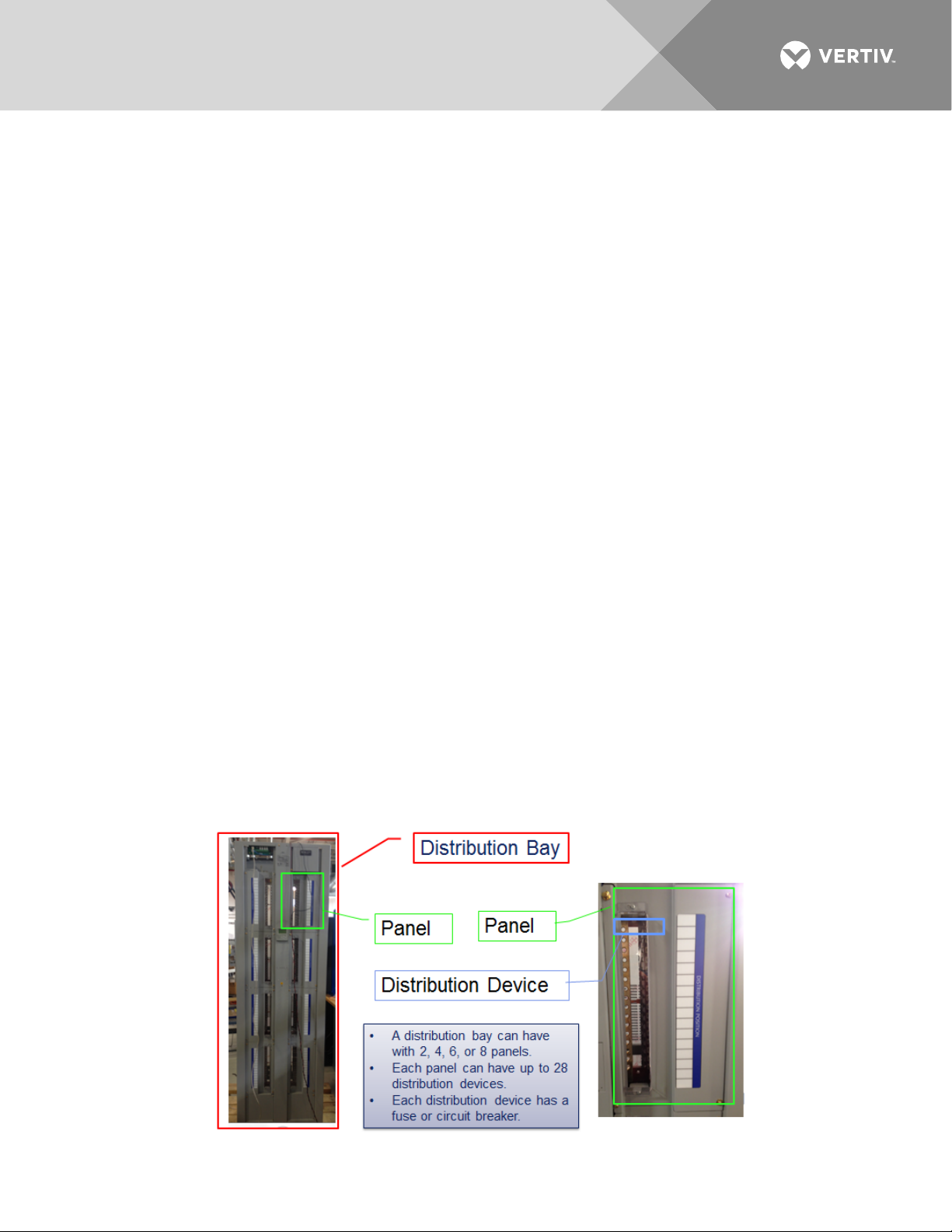
The monitor unit provides voltage, current, and status information about a distribution bay. It provides
summary information about the bay, summary information about each panel in the bay, and detailed information
about each distribution point in a panel. It also uses the consumption map so that the User can display
information about groups of distribution points.
The distribution system is a bay. A bay has locations for 2, 4, 6, or 8 panels. Some of the panel locations can
be empty, for future expansion. Each panel consists of up to 28 distribution devices. A bay has multiple
feeds, which are connections to incoming DC power. One or more panels are connected to each feed.
This picture shows these components:
Vertiv | NetSure Monitor Unit User Manual (UM1M832DNA) | Rev. C
Page 8
8
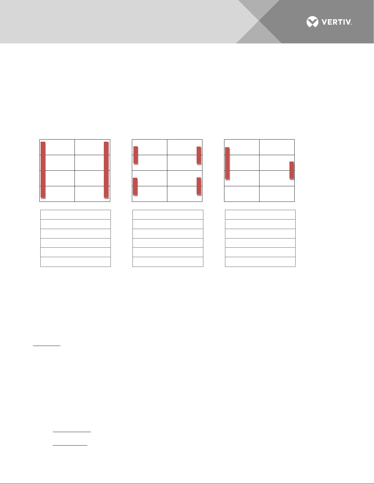
Feed #1: A, C, E, G
Feed #1: A, C
Feed #1: A
Feed #3: B, D
Feed #3: B
Feed #5: H
There is monitor unit for each bay. It is a stand-alone unit that will not manage multiple bays and will not
communicate back to the DC Power Plant which provides power to the bay. Distribution bays do not
communicate with each other; instead, information from multiple distribution bays can be collected by a
Network Management System.
Adjacent panels on each side of the bay can be interconnected, to share the same incoming feed. When panels
are connected together to share the same feed, there is one current and one voltage measurement for the
panel on the same feed.
These diagrams show some of the possible ways that panels can be interconnected:
Panel G Panel H Panel G Panel H Panel G Panel H
Panel E Panel F Panel E Panel F Panel E Panel F
Panel C Panel D Panel C Panel D Panel C Panel D
Panel A Panel B Panel A Panel B Panel A Panel B
2 Feeds 4 Feeds 5 Feeds
Feed #2: B, D, F, H Feed #2: E, G Feed #2: C, E, G
Feed #4: F, H Feed #4: D, F
Each panel can be a standard panel or an advanced panel. For each advanced panel, the monitor unit
measures current and fuse/CB status for each distribution device in the panel. Individual distribution devices
are not measured in a standard panel.
A load (in the consumption map) consists of a set of distribution devices (which can be collected together from
any panel in the bay).
A 2- or 3-pole circuit breaker is treated as one distribution device.
Summary: A bay consists of panels. The panels in a bay are grouped when they share the same feed. An
advanced panel consists of distribution devices. Distribution devices anywhere in the bay can be grouped
together as a load.
Alarm Severity Levels
The available alarms are programmed with an Alarm Severity Level. Each Alarm Severity Level has different
visual/audible alarm attributes. Available Alarm Severity Levels and their attributes are listed in Table 1.
Definition of the Alarm Severity Levels
Alarms can be assigned one of the following alarm severity levels.
Vertiv | NetSure Monitor Unit User Manual (UM1M832DNA) | Rev. C
• Critical Alarm: The fault endangers the systems continued function.
• Major Alarm: The fault reduces the systems functionality.
Page 9

9
Critical Alarm (CR)
ON
--
ON
Observation Alarm (OB)
OFF
ON
OFF
• Observation Alarm: Special operating condition.
Alarms can also set to be not active by assigning “No Alarm” in the alarms severity settings menu.
• No Alarm: The alarm is disabled and no alarm is given.
Table 1:
Alarm Severity Levels
Audible
Alarm Severity Levels Red LED Yellow LED
Alarm
Buzzer
Major Alarm (MJ) ON -- ON
No Alarm (NA) OFF OFF OFF
Notes
1. The alarm indicator turns OFF if the fault(s) that triggered the alarm clears.
2. The audible alarm can be silenced by pressing any key on the monitor unit local interface pad. The
audible alarm is also silenced if the fault(s) that triggered the alarm clears.
3. An audible alarm cutoff feature can be programmed that silences the audible alarm after a preset
programmable time period. The audible alarm can also be disabled.
The available alarms can also be mapped to alarm relays (located on optional interface boards installed in the
system) that can be wired to external alarm circuits.
Data Logs
The monitor unit acquires and analyses real time data from the system's components.
The monitor unit uses this data to process alarms and also records data in logs. The logs are viewed using the
Web Interface and consists of the following. Logs can be saved in the .html (Web page) or .txt (text) format.
• Alarm History Log: Records 4000 latest alarms. The Web Interface displays the latest 500 items.
Alarm log contains a history of alarms. Alarms are added to the alarm log when the alarm condition no
longer exists.
• Event Log: Records 500 latest events. Event log contains a history of key parameter changes made by
Users via the LCD or web pages.
• Data History Log: Records 60000 latest history data. The Web Interface displays the latest 500 items.
Data History log contains historical values for key system data points.
• System Log: Records 3000 items in run log. The Web Interface displays the latest 500 items. System
log contains internal history to assist with field troubleshooting by Vertiv personnel.
NOTE!
entries.
Vertiv | NetSure Monitor Unit User Manual (UM1M832DNA) | Rev. C
For all logs, once maximum number of log entries is reached, new entries overwrite the oldest
Page 10

10
External Interface Functions
10M/100M Ethernet Port Located on Monitor Unit’s Top Panel
An RJ-45 10BaseT jack is provided on the top panel of the monitor unit for connection to a computer for local
access to the monitor unit’s web pages or to a Local Area Network (LAN) for remote access to the monitor
unit’s web pages. This port supports Dynamic Host Configuration Protocol (DHCP) function. For remote
access, the communications cable should be a shielded cable.
NOTE!
Some systems may have an IB4 board with a second Ethernet port. If your system has an IB4
board, DO NOT connect your Local Area Network (LAN) to the monitor unit’s top panel Ethernet port.
10M Ethernet Port Located on Optional IB4 Board (if furnished)
An RJ-45 10BaseT jack is provided on the IB4 board (if furnished in your system) for connection to a Local
Area Network (LAN) for remote access to the monitor unit’s web pages. The communications cable should be
a shielded cable.
IB (Interface Board) (if furnished)
Some systems may be furnished with an IB (Interface Board) connected to the monitor unit.
The IB2 (Interface Board) provides four (4) programmable form C-relay outputs.
The relay outputs can be connected to customer external alarm circuits. Each relay output can be configured
to change state when one or more alarm events occur.
The relay outputs can also be connected to customer external equipment, so that the relay output can control
or interface with the customer external equipment.
TL1
See “TL1 Interface” starting on page 32.
Machine-to-Machine HTTP Interface
See “Machine-to-Machine HTTP Interface” starting on page 33.
Consumption Map (when used with advanced distribution panels)
The monitor unit has a consumption map function accessible via the Web pages. A User can designate a
system’s distribution device (connected to a customer load) to be monitored for consumption. Customer load
consumption parameters for this distribution device are displayed on the consumption map Web page.
Refer to “Consumption Map Tab” on page 65. Refer also to “Consumption Map Settings Tab Programmable
Parameter Descriptions” on page 69.
Vertiv | NetSure Monitor Unit User Manual (UM1M832DNA) | Rev. C
Page 11
11
Menu Navigation Keys
M832D
Status
Indicator (Green)
Minor Alarm
Indicator (Yellow)
Critical or Major
Alarm Indicator (Red)
ESC
ENT
OPERATION
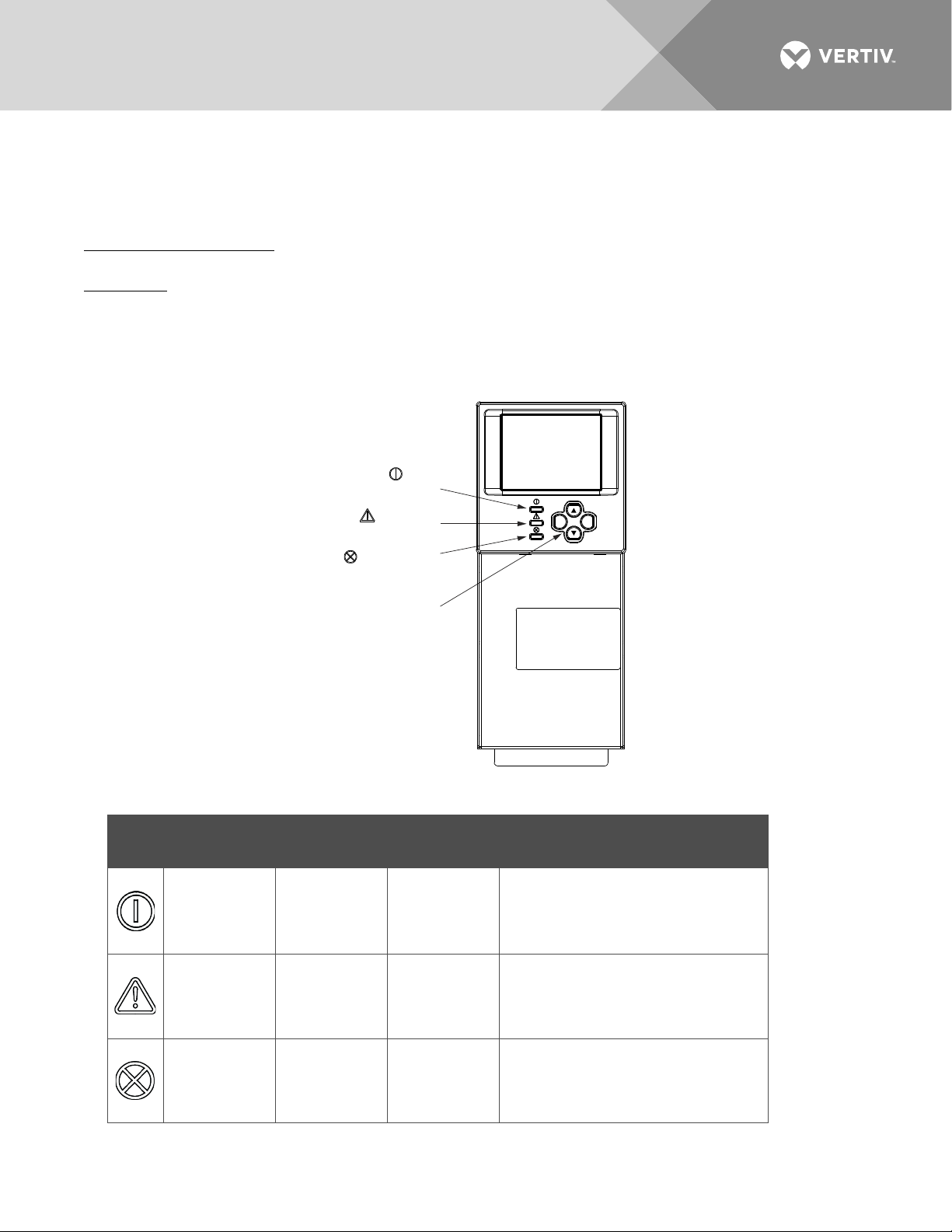
Local Indicators
Location and Identification: Refer to Figure 1.
Description: There are three (3) indicators located on the monitor unit’s front panel. Refer to Table 2 for the
function of the indicators.
Figure 1:
Table 2:
Local Indicators and Menu Navigation Keys Locations
Local Indicators
Vertiv | NetSure Monitor Unit User Manual (UM1M832DNA) | Rev. C
Indicator Normal State Fault State Fault Cause
Status
(Green)
Observation
Alarm
(Yellow)
Major or
Critical Alarm
(Red)
On Off No input power to the monitor unit.
The system has one or more active
Off On
Observation alarms. Alarm
conditions are programmable.
The system has one or more active
Off On
Major or Critical alarms. Alarm
conditions are programmable.
Page 12

12
The User can only read (browse) information in the
Level B (Operator)
none set
The User has access to the system "Control" menus.
The User has full access to all menus; including
Passwords and Privilege Levels
Users (for local and Web access to the monitor unit) are configured via the Web Interface.
NOTE!
change settings. Web access always requires a User name and password to be entered to gain access.
Users are configured with a User Name, password, and privilege level.
User Name: Maximum 8 Characters (0-9, a-z, A-Z, _).
Password: Maximum 13 Characters (0-9, a-z, A-Z, _). Passwords must be at least six (6) characters long.
NOTE!
terminated and the User needs to enter the User name and password again.
Privilege Level: Refer to Table 3. A User has access to his/her privilege level menus, plus all menus of the
lesser privilege levels.
Table 3:
Level A (Browser) none set
Anyone can browse the monitor unit via the local keypad and display. A password is required to
Once there has been no activity (entering data, navigating between pages, etc.), the session is
User Privilege Levels
Privilege Level
Default User Name
and Password
Authority
menus.
The User has access to the system "Settings" menus
Level C (Engineer) none set
Level D (Administrator) admin, 640275
and can download the configuration package. The
User does not have access to update the OS
application and modify, add, or delete Users.
update the OS application and modify, add, and
delete Users.
Multiple Languages Supported
Multiple languages are supported in the Local Interface and Web Interface. Refer to “Language Tab” on page
94.
Using the Local Keypad and Display
Local Menu Navigation Keys and Local Display
Location and Identification: Refer to Figure 1.
Description: There are four (4) menu navigation keys and a local display located on the monitor unit’s front
panel. Refer to Table 4 for the function of the menu navigation keys.
Vertiv | NetSure Monitor Unit User Manual (UM1M832DNA) | Rev. C
Page 13
13
Press this key to go back to a
Up Arrow
Press the up or down arrow keys
NOTE!
local display extinguishes and the monitor unit returns to the Main Menu. Press any key to re-activate
the local display.
Table 4.
Local Menu Navigation Keys
Key Symbol Key Name Function
ESC Escape
ENT Enter
Press any key to silence an audible alarm.
When the local display is lit, if no button is pushed for eight (8) minutes, the backlight of the
previous menu or to cancel
Down Arrow
setting a parameter.
Press this key to go forward to
the next menu, to select a
parameter to edit, or to validate a
parameter setting change.
to scroll through the menus or to
change the value of a parameter.
Press ESC and ENT together to
reset the monitor unit, then press
ENT to accept or ESC to cancel.
--
Local Display Menus
Refer to “Local Display Menus” on page 39.
NOTE!
Navigating the Menus
To Select a Sub-Menu:
Press the UP and DOWN keys to highlight the desired sub-menu.
Press the ENT key to enter the selected sub-menu.
To Select a User and Enter a Password:
To select a User, use the UP and DOWN keys to move the cursor to the Select User field. Press ENT. Use the
UP and DOWN keys to select a User previously programmed into the monitor unit. Press ENT to select the
User. Note that only Users programmed into the monitor unit are shown. Users are programmed via the Web
Interface.
To enter a password, use the UP and DOWN keys to move the cursor to the Enter Password field. Press ENT.
Use the UP and DOWN keys to choose a character. Press ENT to accept and move to the next character.
Continue this process until all characters are entered. Press ENT again to accept the password.
To Change a Parameter:
Press the UP and DOWN keys to move up and down the list of parameters.
Press ENT to select the parameter.
Press the UP and DOWN keys to change the parameter.
Press ENT to make the change. Press ESC to cancel the change.
A valid password is required to access menus that allow changing any power system parameter.
Vertiv | NetSure Monitor Unit User Manual (UM1M832DNA) | Rev. C
Page 14

14
Using the Web Interface
Overview
Via the Web Interface, a User (with proper access level) can:
• View real-time operating information.
• View and download information recorded in logs.
• Send control commands.
• Set programmable parameters.
• Download and upload configuration package.
• Download firmware to the monitor unit.
Multiple Browsers Supported
Multiple browsers are supported in the Web Interface. The User can use Internet Explorer, Chrome, Safari, or
Firefox.
Web Interface Screens
Refer to “Web Interface Screens” on page 52.
Procedures
Setting IPv4 Communications Parameters (if monitor unit not set as DHCP)
The monitor unit’s IPv4 parameters (IP, subnet mask, and gateway addresses) must be set to match your
company’s network settings. The default settings for these parameters are shown below.
• IP Address: 192.168.1.2
• Subnet Mask Address: 255.255.255.0
• Gateway Address: 192.168.1.1
Local Menu Navigation:
Main Menu / Settings Icon / Comm Settings / enter parameters.
Web Menu Navigation:
Advance Settings Menu / Ethernet Tab / enter parameters.
Setting IPv6 Communications Parameters (if monitor unit not set as DHCPv6)
The monitor unit’s IPv6 parameters (IPv6 address, IPv6 prefix, and IPv6 gateway address) must be set to match
your company’s network settings. The default settings for these parameters are shown below.
• Link-Local Address: fe80:209:f5ff:fe09:1002/64
• IPv6 Address: 20fa:fffd:fffc:fffb:fffa:fff9:fff8:fff7
• IPv6 Prefix: 0
• IPv6 Gateway: 20fa:1:fffe:ffff:fffe:fffd:ffff:fffe
Vertiv | NetSure Monitor Unit User Manual (UM1M832DNA) | Rev. C
Page 15

15
Local Menu Navigation:
Main Menu / Settings Icon / Comm Settings / enter parameters.
Web Menu Navigation:
Advance Settings Menu / Ethernet Tab / enter parameters.
Setting for DHCP and DHCPv6
The DHCP and DHCPv6 functions allow the monitor unit to acquire an IP address automatically. This function
can only be enabled or disabled via the local display and keypad. If this function is enabled and the acquisition
of an IP address fails, an alarm is generated. If the acquisition of an IP address is successful, you need to record
the IP address automatically acquired by the monitor unit to access the monitor unit via the Web Interface.
This IP address is displayed on the main system info screen (Main Menu / ESC) in the IP Address field or in the
local display menu (Main Menu / Settings Icon / Comm Settings) in the IP Address field below the DHCP
setting.
Local Menu Navigation:
Main Menu / Settings Icon / Comm Settings / DHCP (set to enabled) (can also view acquired IP address).
Main Menu / ESC (to view acquired IP address).
Web Menu Navigation:
None.
Connecting the Monitor Unit to your Local Area Network (LAN) when the System is NOT Equipped with an IB4 Board
An Ethernet port is located on the top panel of the monitor unit. This port supports Dynamic Host
Configuration Protocol (DHCP) function.
If your system does not have an IB4 board, connect the Local Area Network (LAN) to the monitor unit’s top
panel port. This port can be assigned an IP address or can be set for DHCP. If set for DHCP, it will get its IP
address from a DHCP server on the network. Refer to “Setting IPv4 Communications Parameters (if monitor
unit not set as DHCP)” on page 14 or “Setting IPv6 Communications Parameters (if monitor unit not set as
DHCPv6)” on page 14 to set the port parameters;
or,
“Setting for DHCP and DHCPv6” on page 15 to set the port as DHCP or DHCPv6.
Connecting the Monitor Unit to your Local Area Network (LAN) when the System IS Equipped with an IB4 Board
NOTE!
Your system may be furnished with an IB4 board. The IB4 board provides a second Ethernet
port. The Ethernet port located on the monitor unit’s top panel can ONLY be used to connect a
computer directly to the monitor unit. The Ethernet port located on the IB4 board can be used to
connect the monitor unit to your Local Area Network (LAN). Refer to your system’s documentation for
location of the IB4 board (if furnished).
NOTE!
If your system has an IB4 board, DO NOT connect your Local Area Network (LAN) to the
monitor unit top Ethernet port.
Some systems may have an IB4 board with a second Ethernet port. This port supports Dynamic Host
Configuration Protocol (DHCP) function. Refer to your system’s documentation for location of the IB4 board (if
furnished).
Vertiv | NetSure Monitor Unit User Manual (UM1M832DNA) | Rev. C
Page 16

16
If your system has an IB4 board, connect the Local Area Network (LAN) to the IB4 board port. The IB4 board
port can be assigned an IP address or can be set for DHCP. If it is set for DHCP, it will get its IP address from a
DHCP server on the network. Refer to “Setting IPv4 Communications Parameters (if monitor unit not set as
DHCP)” on page 14 or “Setting IPv6 Communications Parameters (if monitor unit not set as DHCPv6)” on page
14 to set the port parameters;
or,
“Setting for DHCP and DHCPv6” on page 15 to set the port as DHCP or DHCPv6.
Connecting a Local Computer Directly to the Monitor Unit when the System is NOT Equipped with an IB4 Board
An Ethernet port is located on the top panel of the monitor unit. This port supports Dynamic Host
Configuration Protocol (DHCP) function.
If your system does not have an IB4 board, perform the following procedure.
Procedure
1. Before connecting your computer directly to the monitor unit’s Ethernet port, use the following
procedure to record your computer’s network settings (so they can be returned to these values when
done) and then change these settings in your computer to match the communications settings
programmed in the monitor unit.
NOTE!
a) Record your computer’s network settings by launching Control Panel in your computer. Navigate
through Network and Sharing Center Local Area Connection Properties Internet Protocol
Version 4 (TCP/IPV4) Properties.
b) Record whether the "Obtain an IP address automatically" or "Use the following IP address" button is
selected. If "Use the following IP address" button is selected, also record the following:
IP Address:
Subnet Mask:
Default Gateway:
c) Record your monitor unit’s network settings by navigating the monitor unit’s local display panel to
Main Menu / Settings Icon / Comm Settings. Record the following monitor unit’s IP parameters. If
these parameters were not changed, they should be at the default values as shown in the example
section below.
IPv4
IP Address:
Subnet Mask:
Default Gateway:
Example:
IP Address: 192.168.1.2
Subnet Mask: 255.255.255.0
Default Gateway: 192.168.1.1
Windows 7 operating system is used in this procedure, other operating systems are similar.
IPv6
IPv6 Address:
IPv6 Prefix:
Vertiv | NetSure Monitor Unit User Manual (UM1M832DNA) | Rev. C
Page 17

17
IPv6 Gateway:
Example:
IPv6 Address: 20fa:fffd:fffc:fffb:fffa:fff9:fff8:fff7
IPv6 Prefix: 0
IPv6 Gateway: 20fa:1:fffe:ffff:fffe:fffd:ffff:fffe
d) Change your local computer’s network settings using the information you acquired in the above
step, except that the last part of the IP address needs to be replaced with any different number.
IPv4
IP Address:
Subnet Mask:
Default Gateway:
Example:
IP Address: 192.168.1.3
Subnet Mask: 255.255.255.0
Default Gateway: 192.168.1.1
IPv6
IPv6 Address:
IPv6 Prefix:
IPv6 Gateway:
Example:
IPv6 Address: 20fa:fffd:fffc:fffb:fffa:fff9:fff8:fff7
IPv6 Prefix: 0
IPv6 Gateway: 20fa:1:fffe:ffff:fffe:fffd:ffff:fffe
e) Select OK. Note that you may have to reboot your local computer for the settings to take effect.
Follow any instruction you see on the screen.
2. Connect your computer directly to the monitor unit’s Ethernet port (RJ-45 jack located on the top of
the monitor unit). See Figure 1. The monitor unit’s top panel port is configured with an IP address.
Default is 192.168.1.2. This is the address you will type into your Web browser to access the monitor
unit’s Web Interface. You will also have to set the properties on your computer (refer to the previous
procedure in step 1).
3. When finished, disconnect your computer from the monitor unit and, if necessary, reset your computer
network settings as recorded in step 1.
Connecting a Local Computer Directly to the Monitor Unit when the System IS Equipped with an IB4 Board
NOTE!
Your system may be furnished with an IB4 board. The IB4 board provides a second Ethernet
port. The Ethernet port located on the monitor unit’s top panel can ONLY be used to connect a
computer directly to the monitor unit. The Ethernet port located on the IB4 board can be used to
connect the monitor unit to your Local Area Network (LAN). Refer to your system’s documentation for
location of the IB4 board (if furnished).
An Ethernet port is located on the top panel of the monitor unit. This port supports Dynamic Host
Configuration Protocol (DHCP) function.
Vertiv | NetSure Monitor Unit User Manual (UM1M832DNA) | Rev. C
Page 18
18
Some systems may have an IB4 board with a second Ethernet port. Refer to your system’s documentation for
location of the IB4 board (if furnished).
If your system has an IB4 board, perform the following procedure.
Procedure
1. Connect your computer directly to the monitor unit’s Ethernet port (RJ-45 jack located on the top of the
monitor unit). See Figure 1. The monitor unit’s top panel port will have the following IPv4 Address:
192.168.100.100. Enter the address 192.168.100.100 in your Web browser to access the monitor unit’s
Web Interface via IPv4. The monitor unit’s top panel port will have the following IPv6 Address. IPv6
Link-Local Address: fe80::209:f5ff:fe09:1002/64 or IPv6 Address: 20fa:fffd:fffc:fffb:fffa:fff9:fff8:fff7. Enter
the IPv6 Link-Local Address: [fe80::209:f5ff:fe09:1002/64] or IPv6 Address:
[20fa:fffd:fffc:fffb:fffa:fff9:fff8:fff7] to access the monitor unit’s Web Interface via IPv6.
2. When finished, disconnect your computer from the monitor unit.
Disabling Proxy Server Settings to Enable a Connection to the Monitor Unit over an Intranet Network (if required)
NOTE!
This procedure needs to be performed only when the monitor unit is connected to an Intranet
and the User’s computer is set to access the Intranet through a proxy server. Note that if the monitor
unit is connected to the Internet and the User’s computer is connected to an Intranet, the User may not
be able to disable the proxy server and access the monitor unit.
If the monitor unit’s Ethernet port is connected to your company’s Intranet Network and your computer is also
connected to the Intranet Network but requires access via a proxy server, you must disable the proxy server
settings to access the monitor unit. Follow the procedure below to disable the proxy server settings.
Procedure
NOTE!
Internet Explorer is used in this procedure, other browsers are similar.
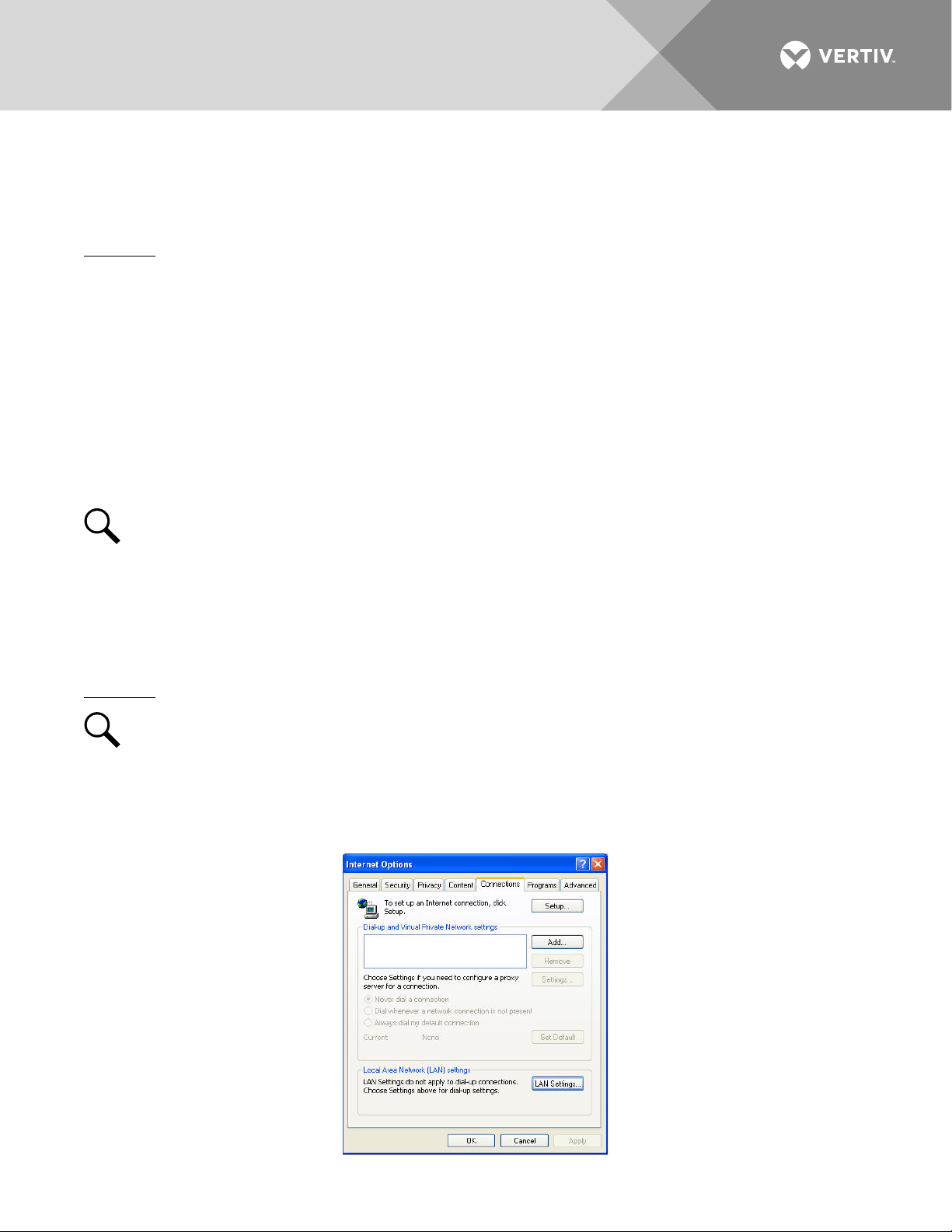
1. Launch “Internet Explorer”.
2. Select
Options” window, select the
Internet Options
from the
Tools
Connections
menu. The “Internet Options” window opens. In the “Internet
tab.
Vertiv | NetSure Monitor Unit User Manual (UM1M832DNA) | Rev. C
Page 19
19
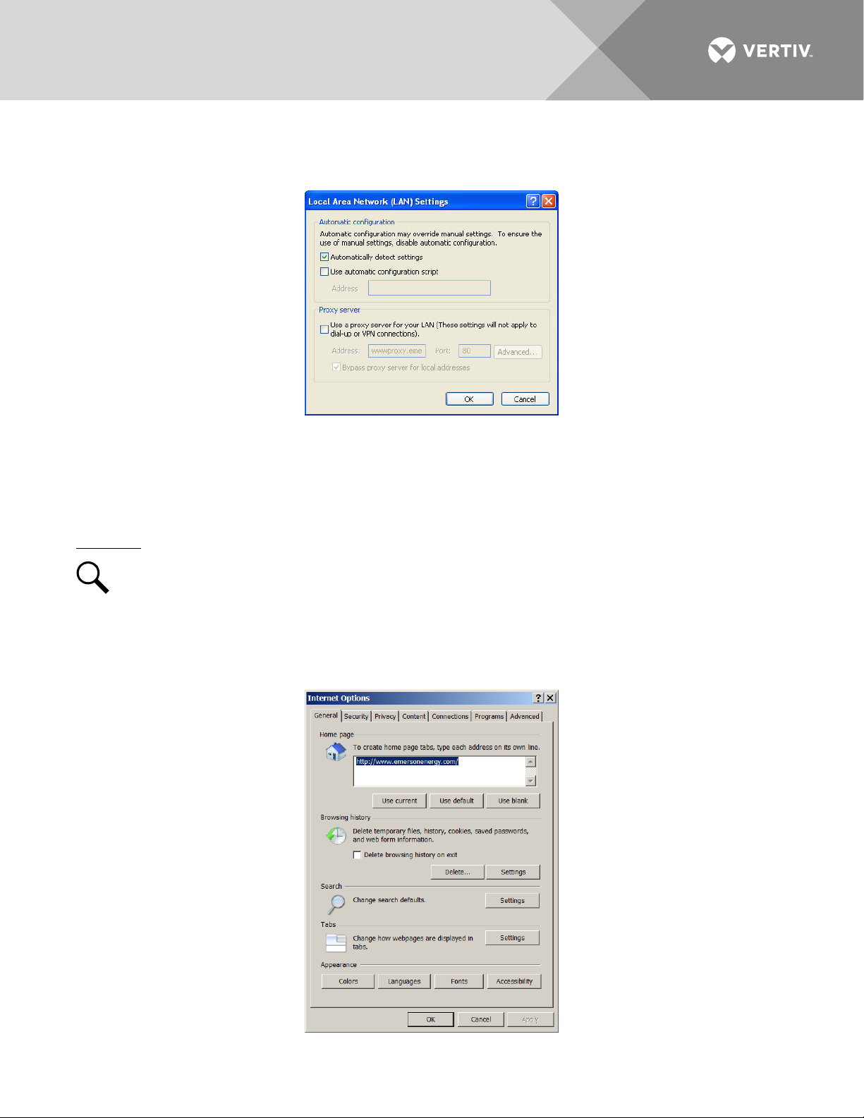
3. Click on the
LAN Settings...
button. The following window opens. In the LAN Settings window,
uncheck the Proxy Server box and click OK.
Internet Security Settings for Loading Files or Downloading Files into the Monitor Unit
Your computer’s security settings may prevent you from loading files or downloading files into the monitor unit.
Refer to the following procedure to set your computer’s security settings to allow for this.
Procedure
NOTE!
Internet Explorer is used in this procedure, other browsers are similar.
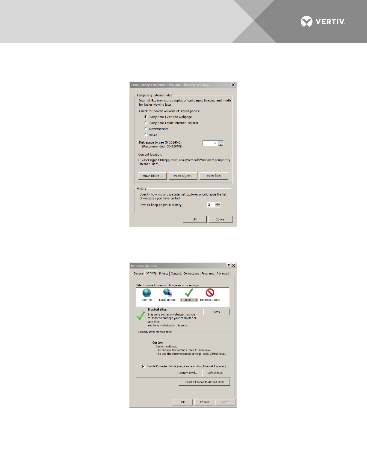
1. Launch “Internet Explorer”.
2. Select
Internet Options
Options” window, select the
from the
General
Tools
menu. The “Internet Options” window opens. In the “Internet
tab.
Vertiv | NetSure Monitor Unit User Manual (UM1M832DNA) | Rev. C
Page 20
20
3. Under “Browsing History”, click on the
window, choose “
Every time I visit the webpage
Settings
button. The following window opens. In the
” and click OK.
Settings
4. In the “Internet Options” window, select the
Security
tab.
Vertiv | NetSure Monitor Unit User Manual (UM1M832DNA) | Rev. C
Page 21
21
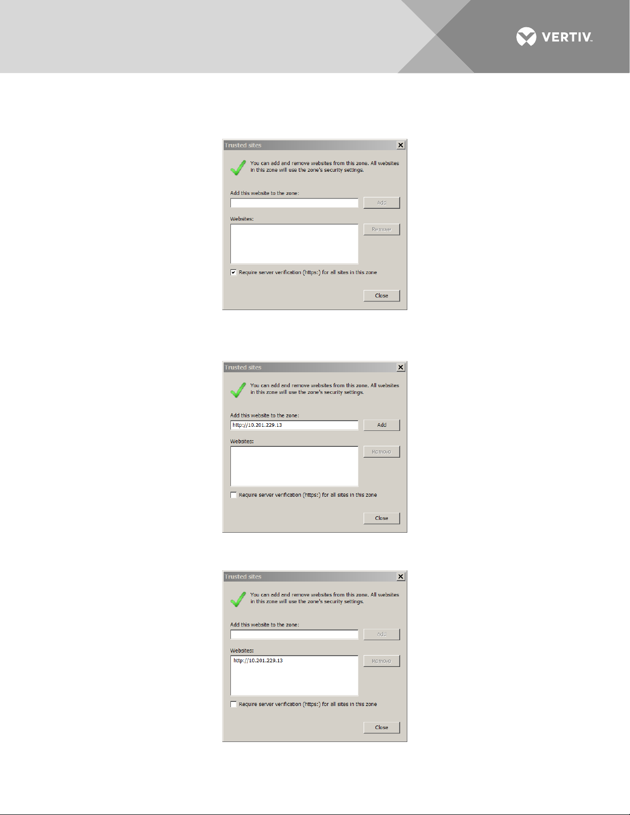
5. Click on
Trusted sites
. With “
Trusted sites
” selected, click “
Sites
”. The following window opens.
Uncheck the “Require server verification (https:) for all sites in the zone:” box if https is not being used.
6. In the
Trusted sites
window, type or copy the monitor unit URL in the “
Add this website to the zone:
box.
”
7. Click
Vertiv | NetSure Monitor Unit User Manual (UM1M832DNA) | Rev. C
Add
. The monitor unit URL is listed in the
Websites
: box. Click
Close
.
Page 22
22
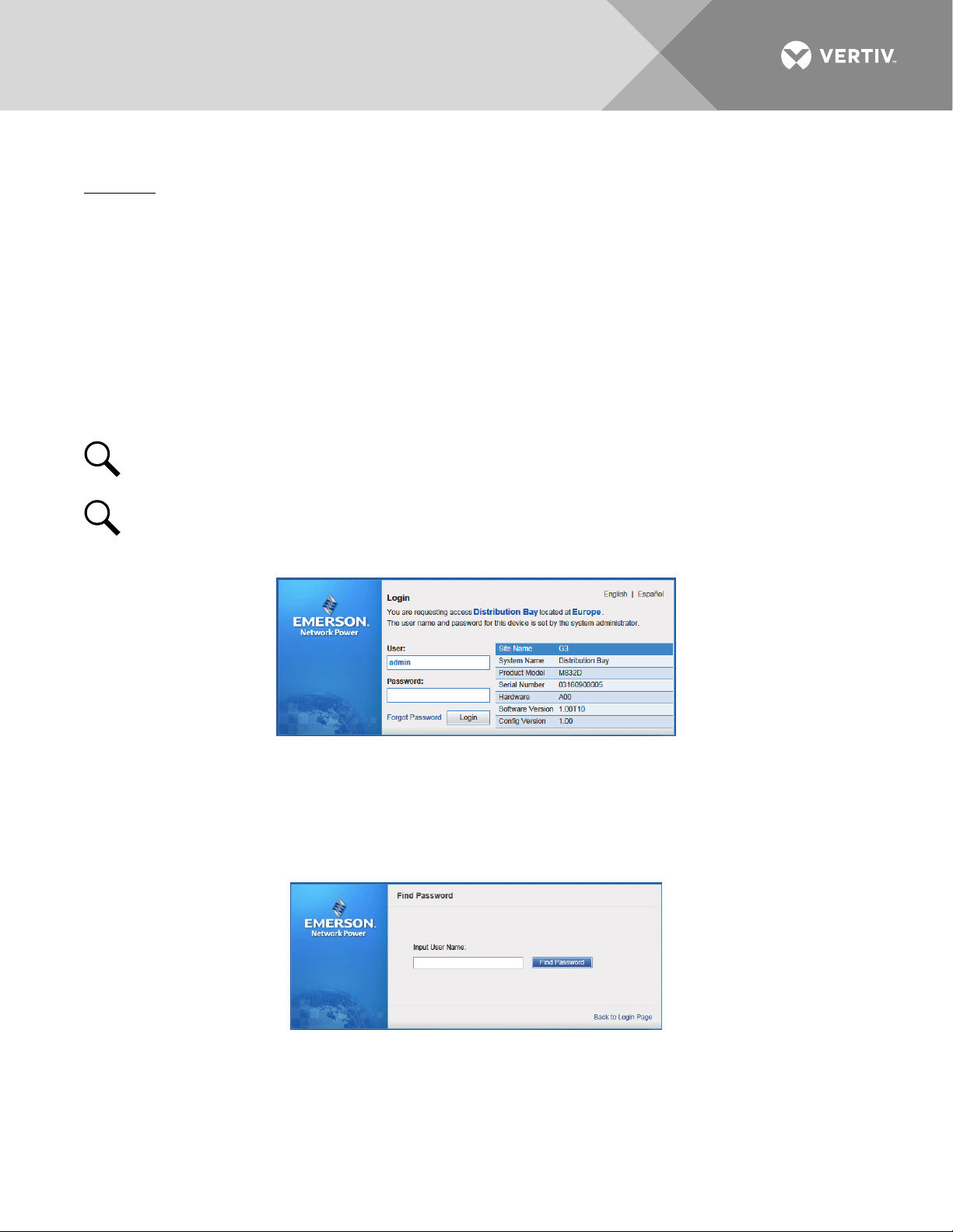
Logging into the Monitor Unit
Procedure
Internet Explorer, version 6 or newer, is supported (IE 8.0 is recommended). Chrome, Safari, and Firefox are also
supported.
1. In your browser, enter http:// and the monitor unit’s IP address (see “Connecting a Local Computer
Directly to the Monitor Unit when the System is NOT Equipped with an IB4 Board” on page 16 or
“Connecting a Local Computer Directly to the Monitor Unit when the System IS Equipped with an IB4
Board” on page 17) and press
ENTER
. If your site requires secure HTTP and you were furnished with an
monitor unit configuration with secure HTTP, enter https:// and the monitor unit’s IP address and press
ENTER
.
2. The following Web Interface Login window opens. Enter a valid
LOGIN
NOTE!
.
By default, the “User Name” is "admin" and the “Password” is “640275”. The password can be
User Name
and
Password
changed if necessary (see “Users Tab” on page 89).
NOTE!
Before entering a User Name and password, you can select a local language that the Web
Interface menus use from those listed in the top right corner of the login window. See “Language Tab”
on page 94.
3. After entering a valid
User Name
and
Password
and clicking
LOGIN
, the Web Interface "HOMEPAGE"
window opens. Refer to “Web Interface Screens” on page 52.
You can program a “Forgot Password” feature. Once programmed, if you forgot your password, click
Password
Password
in the login screen. A "Find Password" window opens. Enter your User Name and click
. The monitor unit sends the password to the email address programmed for this User Name.
, then click
Forgot
Find
• To set up the “Forgot Password” feature, you must have a User set up with an email address and you
must set up the Alarm Reporting SMTP section. To program the User, in the Web Interface, go to
Advanced Settings Menu / Users Tab / select the User / enter a valid email address for this User /
repeat for all Users (see “Users Tab” on page 89). To program the Alarm Reporting SMTP section, in the
Web Interface, go to Advanced Settings Menu / Alarm Report Tab / SMTP Section / enter at a minimum
Vertiv | NetSure Monitor Unit User Manual (UM1M832DNA) | Rev. C
Page 23

23
the following parameters: “Email To” address, Server IP (IPV4 Server address), Server Port, “Email From”
address. If email authentication is required, then the SMTP Account and SMTP Password needs to be
configured as well. (See “Alarm Report Tab” on page 104.)
Common Tasks Performed via the Local Keypad and/or Web Interface
Procedures
Refer also to “Local Display Menus” on page 39 and “Web Interface Screens” on page 52 for menu item
descriptions.
NOTE!
Ensure current configuration is backed up prior to changing settings (see “Backing Up the
Monitor Unit Configuration” on page 28). Create new backup files after every successful update for your
records and in case of monitor unit failure.
Setting Bay Parameters
Local Menu Navigation:
Main Menu / Settings Icon / Bay Settings.
Web Menu Navigation:
Home Page / Distribution Bay Tab / see “Distribution Bay Settings Web Page” on page 56.
Setting Input Feeds Parameters
Local Menu Navigation:
Main Menu / Settings Icon / Feeds Settings.
Web Menu Navigation:
Home Page / Distribution Bay Tab / see “Feed Settings Web Page” on page 58.
Setting Distribution Panels Parameters
Local Menu Navigation:
Main Menu / Settings Icon / Panel Settings.
Web Menu Navigation:
Home Page / Distribution Bay Tab / see “Standard Distribution Panel Settings Web Page” on page 61 and
“Advanced Distribution Panel Settings Web Page” on page 63.
Changing the Date and Time
Local Menu Navigation:
Main Menu / Settings Icon / Sys Settings / Date.
Main Menu / Settings Icon / Sys Settings / Time.
Vertiv | NetSure Monitor Unit User Manual (UM1M832DNA) | Rev. C
Page 24
24
Date: Use the Up Arrow and Down Arrow to select the date field. Press ENT. Use Up Arrow and Down
Arrow to select the year then press ENT, next use Up Arrow and Down Arrow to select the month then
press ENT, and finally use Up Arrow and Down Arrow to select the day then press ENT.
Time: Use the Up Arrow and Down Arrow to select the time field. Press ENT. Use Up Arrow and Down
Arrow to select the hour then press ENT, next use Up Arrow and Down Arrow to select the minute then
press ENT, and finally use Up Arrow and Down Arrow to select the second then press ENT.
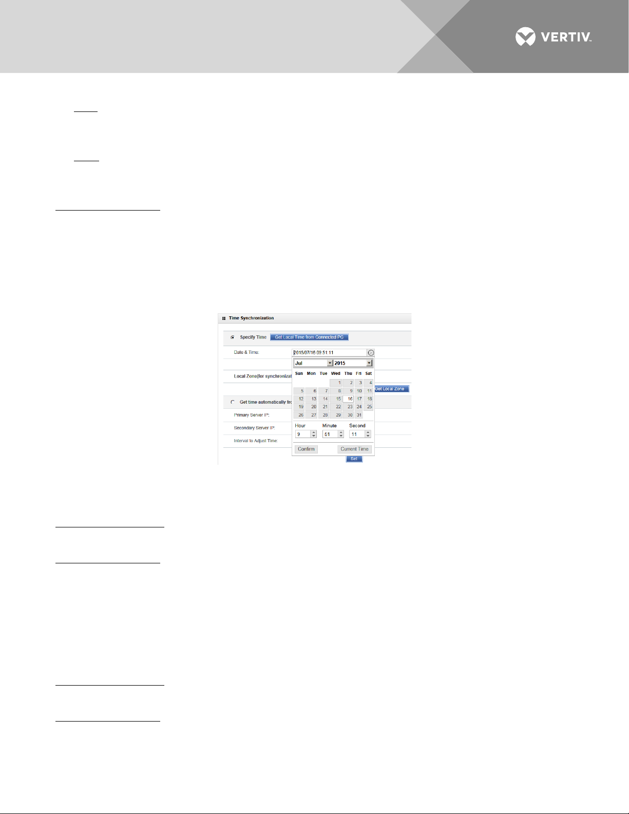
Web Menu Navigation:
Settings Menu / Quick Settings Tab / Time Settings.
In the Specify Time section, click on "Get Local Time from Connected PC" and then “Set” to automatically
set the date and time. To manually set the date and time, click on “the clock symbol” and enter the date
and time. See Figure 2. Then select the “Confirm” button. Then click on “Set” to save the change.
Figure 2:
Manual Date and Time Menu
Adding, Deleting, and Modifying Users
Local Menu Navigation:
None.
Web Menu Navigation:
Advance Settings Menu / Users Tab.
Setting IP Communications Parameters (if monitor unit not set as DHCP or DHCPv6)
See also “Setting IPv4 Communications Parameters (if monitor unit not set as DHCP)” on page 14 and “Setting
IPv6 Communications Parameters (if monitor unit not set as DHCPv6)” on page 14.
Local Menu Navigation:
Main Menu / Settings Icon / Comm Settings / enter parameters.
Web Menu Navigation:
Advance Settings Menu / Ethernet Tab / enter parameters.
Vertiv | NetSure Monitor Unit User Manual (UM1M832DNA) | Rev. C
Page 25

25
Setting for DHCP and DHCPv6
The DHCP and DHCPv6 functions allow the monitor unit to acquire an IP address automatically. This function
can only be enabled or disabled via the local display and keypad. If this function is enabled and the acquisition
of an IP address fails, an alarm is generated. If the acquisition of an IP address is successful, you need to record
the IP address automatically acquired by the monitor unit to access the monitor unit via the Web Interface.
This IP address is displayed on the main system info screen (Main Menu / ESC) in the IP Address field or in the
local display menu (Main Menu / Settings Icon / Comm Settings) in the IP Address field below the DHCP
setting.
Local Menu Navigation:
Main Menu / Settings Icon / Comm Settings / DHCP (set to enabled) (can also view acquired IP address).
Main Menu / ESC (to view acquired IP address).
Web Menu Navigation:
None.
Setting SNMP Parameters
Local Menu Navigation:
None.
Web Menu Navigation:
Advance Settings Menu / SNMP Tab.
Setting TL1 Parameters
Refer to the following procedures.
Setting TL1 Protocol Parameters
Local Menu Navigation:
None.
Web Menu Navigation:
Advance Settings Menu / Monitor Protocol Tab (set to TL1), then click the “Valid after Restart" button. Set the
TL1 protocol parameters as described under “TL1 Protocol” on page 116.
Setting TL1 Access Identifiers and Sub-Access Identifiers
Local Menu Navigation:
None.
Web Menu Navigation:
Advance Settings Menu / TL1 AID Group Tab. Set the TL1 access identifiers and sub-access identifiers as
described under “TL1 AID Group Tab” on page 118.
Enabling/Disabling and Configuring Pre-Defined TL1 Signals
Local Menu Navigation:
None.
Vertiv | NetSure Monitor Unit User Manual (UM1M832DNA) | Rev. C
Page 26

26
Web Menu Navigation:
Advance Settings Menu / TL1 AID Signal Tab. Assign signals to the TL1 access identifiers as described under
“TL1 AID Signal Tab” on page 120.
Assigning Severity Level to Alarms
Local Menu Navigation:
None.
Web Menu Navigation:
Advance Settings Menu / Alarms Tab and DI Alarms Tab.
Assigning Relays to Alarms
Local Menu Navigation:
None.
Web Menu Navigation:
Advance Settings Menu / Alarms Tab and DI Alarms Tab.
Setting Digital Inputs
Local Menu Navigation:
None.
Web Menu Navigation:
Advance Settings Menu / DI Alarms Tab
Disabling the Local Keypad Sound
Local Menu Navigation:
Main Menu / Settings Icon / Sys Settings / Keypad Voice.
Web Menu Navigation:
None.
Programming the Audible Alarm Feature
Local Menu Navigation:
Main Menu / Settings Icon / Sys Settings / Audible Alarm.
Web Menu Navigation:
None.
Blocking Alarms
Local Menu Navigation:
None.
Vertiv | NetSure Monitor Unit User Manual (UM1M832DNA) | Rev. C
Page 27

27
Web Menu Navigation:
Settings Menu / Quick Settings Tab / Outgoing Alarms Blocked.
Viewing Alarms
Local Menu Navigation:
Main Menu / Alarm Icon / ENT.
Web Menu Navigation:
Active alarms are listed in the lower right window pane. If the window pane is collapsed, click the "arrow" icon
to expand the alarm list.
Viewing System Status
Local Menu Navigation:
Main Menu / Bay Current Icon / ENT.
Main Menu / Input Feeds Current and Voltage Icon / ENT.
Main Menu / Distribution Panel Icons / ENT.
Web Menu Navigation:
System status is displayed in the right window pane of the Home page. Select the Distribution Bay tab and use
the interactive links to view the various system elements status pages. Select the Bay Data tab to view basic
bay data. See “Distribution Bay Tab” on page 55 and “Consumption Map Tab” on page 65.
Viewing the Monitor Unit’s Device Inventory
Local Menu Navigation:
Main Menu / ESC to view Info Screens / ENT to view Inventory.
Web Menu Navigation:
System Inventory Menu.
Clearing Data
Local Menu Navigation:
Main Menu / Settings Icon / select “Clear Datas” in the various settings menus.
Web Menu Navigation:
Home Page / Distribution Bay Tab / navigate the various interactive elements screens and select Clear Data in
the settings screens.
Clearing Logs
Local Menu Navigation:
None.
Web Menu Navigation:
Advance Settings Menu / Clear Data Tab / select log to clear.
Vertiv | NetSure Monitor Unit User Manual (UM1M832DNA) | Rev. C
Page 28

28
Using the Relay Test Feature
NOTE!
The relay test can only be performed when no alarms are present.
Refer to the following procedures.
Automatic Test
When placed in Relay Automatic Test Mode; all relays on an IB2 board de-energize (since Fail Safe is enabled,
relay 1on the 1st IB2 will be in alarm state, if wired for fail safe), then one-by-one each relay energizes for the
time period selected and then de-energizes. Relay 1 will stay in the alarm state during the rest of the relay tests.
Local Menu Navigation:
None.
Web Menu Navigation:
Advance Settings Menu / DO (Relay) Tab / set the Relay Test Time.
then
Advance Settings Menu / DO (Relay) Tab / Relay Test (set to Automatic).
NOTE!
The relay test can be exited at any time by setting the Relay Test to Disabled.
Manual Test
When placed in Relay Manual Test Mode, all relays on an interface board de-energize (since Fail Safe is enabled
relay 1 on the IB2 will be in alarm state, if wired for fail safe). Then you can individually change each relay’s
state. The relay changes state for the time period selected. At the end of the test, all relays are returned to
their normal state (if no alarms are present).
Local Menu Navigation:
None.
Web Menu Navigation:
Advance Settings Menu / DO (Relay) Tab / Relay Test (set to Manual).
then
Advance Settings Menu / DO (relay) / Relay (select the other state) then press the SET button.
then
Advance Settings Menu / DO (Relay) Tab / Relay Test (set to Disabled).
Backing Up the Monitor Unit Configuration
There are two steps in backing up the system’s monitor unit configuration:
• Save the monitor unit configuration package. This package includes the base configuration and any
changes made to alarm severity levels, relay assignments, and signal names.
ALERT! This file is NOT forward compatible.
• Save a file named "SettingParam.tar". This file contains changes made to system parameter settings and
alarm setpoints. A file named "SettingParam.tar" is automatically created/appended by the monitor unit
whenever a User (or the factory at the time of shipment) makes changes to parameter settings via the
Vertiv | NetSure Monitor Unit User Manual (UM1M832DNA) | Rev. C
Page 29

29
local display or Web Interface. This file can be saved to your computer so you can restore any custom
settings you may have made.
NOTE!
It is strongly recommended that you save a copy of the SettingParam.tar file whenever you
customize any parameter settings. Then, if you ever replace the monitor unit or perform a "Restore
Defaults" procedure, you can restore your customized settings by downloading the previously saved
SettingParam.tar file back into the monitor unit.
Prior to changing settings, ensure the current configuration package and "SettingParam.tar" files are backed up.
After making changes, create new backup files.
To aid in file management, you may change the name of the configuration package "app_cfg.tar" to differentiate
it from other "app_cfg.tar" files saved. The new name can use alpha and numeric characters preceding the
original "app_cfg.tar" name (the end of the new file name must always be "app_cfg.tar"; for example, an
acceptable filename would be "seville4app_cfg.tar").
To aid in file management, you may change the name of the "SettingParam.tar" file to differentiate it from other
"SettingParam.tar" files saved. The new name can use alpha and numeric characters preceding the original
"SettingParam.tar" name (the end of the new file name must always be "SettingParam.tar"; for example, an
acceptable filename would be "seville4SettingParam.tar").
Refer to the following procedures.
Saving the Configuration Package
Local Menu Navigation:
None.
Web Menu Navigation:
Advance Settings Menu / SW Maintenance Tab.
See “Upload/Download Procedure” on page 99 to save the "Configuration Package" to your computer.
Saving the SettingParam.tar File
Local Menu Navigation:
None.
Web Menu Navigation:
Advance Settings Menu / SW Maintenance Tab.
See “Retrieve SettingParam.tar Procedure” on page 98 to retrieve the SettingParam.tar file.
Reloading a Backed-Up Monitor Unit Configuration
There are two steps in reloading a backed-up monitor unit configuration.
• One step to reload the saved monitor unit configuration package.
• One step to reload the saved "SettingParam.tar" file.
Refer to the following procedures.
Reloading the Configuration Package
Local Menu Navigation:
None.
Vertiv | NetSure Monitor Unit User Manual (UM1M832DNA) | Rev. C
Page 30

30
Web Menu Navigation:
Advance Settings Menu / SW Maintenance Tab.
See “Upload/Download” on page 99 to download a configuration package into the monitor unit.
Reloading the SettingParam.tar File
Local Menu Navigation:
None.
Web Menu Navigation:
Advance Settings Menu / SW Maintenance Tab.
See “Upload/Download Procedure” on page 99 to download a "SettingParam.tar" file into the monitor unit.
Upgrading the Monitor Unit Using an Application ("All") Package
This procedure is typically used to upgrade your monitor unit when a new release of firmware is available for
you application. The name of the Application "All" Package file must end in .tar or .tar.gz. An Application “All”
package file has both the application (software) and configuration package and is usually supplied for an
application upgrade.
A User can copy an Application ("All") Package from your computer to a USB memory device. You can then
place the USB memory device into the monitor unit USB port and then download the file into the monitor unit.
If upgrading the monitor unit with a USB drive other than the supplied USB, the following USB drive
specifications must be adhered to:
• USB 2.0 or below, 32G or less, formatted fat32 file system.
Refer to the following procedures.
Local Menu Navigation (To Download an Application ("All") Package):
1. Copy the file to a USB memory device. The file must be in the root directory of the USB memory device.
The file must be named app_V#.#.##.tar.gz.
NOTE!
#.#.## is the revision number (i.e. 1.1.40, 4.1.40, etc.).
2. Connect the USB memory device to the USB port on the top of the monitor unit.
3. Navigate to “Main Menu / Settings Icon / Sys Settings / Update App / select yes”. Once Yes is selected
and confirmed, the configuration file located on the memory device located in the monitor unit's USB
port is loaded into the monitor unit.
4. Return to the Main Screen, and then reboot the monitor unit (press ENT and ESC at the same time).
5. The screen displays "OK to reboot? ESC to cancel! ENT to OK." Press ENT to reboot.
6. The monitor unit enters an initialization routine, which takes a few minutes. The routine is complete
and the monitor unit is operational when normal system voltage is displayed on the screen.
7. Remove the memory device.
Web Menu Navigation (To Download an Application ("All") Package):
Advance Settings Menu / SW Maintenance Tab. See “Upload/Download Procedure” on page 99 to download
an Application (“All”) Package into the monitor unit.
Vertiv | NetSure Monitor Unit User Manual (UM1M832DNA) | Rev. C
Page 31

31
Restoring Factory Default Configuration
This procedure is typically used to restore any changes made to any settings, relay assignments, alarm
severities, or signal names. This file is not shipped with the system. There are one or two steps required to
restore your monitor unit as shipped.
• One step to restore the factory default configuration (required only if you made any changes to relay
assignments, alarm severities, or signal names).
• One step to reload the "SettingParam.tar" file (required only if you made any system parameter settings
and alarm setpoints change).
Your system may have been configured for specific options at the factory which creates a
“SettingParam.tar” file. Restoring the factory default configuration returns the system to the settings of
the default configuration. These are the settings before specific options may have been configured by
the factory. To restore the system to the settings as shipped, after restoring the factory default
configuration, you must reload the factory “SettingParam.tar” file.
NOTE!
If a system was shipped with factory modified settings, the system may be supplied with a USB
memory device that contains a “SettingParam.tar” file as shipped. If provided, the “SettingParam.tar” file
has a seven-digit UIN (Unique Identification Number) preceding the “SettingParam.tar” filename. The
UIN identifies a “SettingParam.tar” file for use with a specific system. This file can be used to restore
your system to the configuration as shipped. Refer to “Reloading a Backed-Up Monitor Unit
Configuration” on page 29 to reload the supplied “SettingParam.tar” file.
Procedure
ALERT! When this procedure is performed, the monitor unit’s existing configuration and parameter
settings will be lost. The “SettingParam.tar” file is deleted. Before restoring the factory default
configuration, if you have made changes to any setting save the “SettingParam.tar” file or if you have
made any name changes, relay assignments, or alarm severities save the configuration package (see
Backing Up the Monitor Unit Configuration on page 28).
AFTER PERFORMING THIS PROCEDURE, RELOAD THE “SETTINGPARAM.TAR” FILE AND
CONFIGURATION PACKAGE, IF REQUIRED.
Local Menu Navigation:
Main Menu / Settings Icon / Sys Settings / Restore Default.
Web Menu Navigation:
Advance Settings Menu / SW Maintenance Tab.
See “Restore Factory Default Configuration Procedure” on page 96.
Rebooting the Monitor Unit
Local Menu Navigation:
At the Main Screen, press ENT and ESC at the same time to reset the monitor unit.
Web Menu Navigation:
Advance Settings Menu / SW Maintenance Tab / Reboot Controller button.
Vertiv | NetSure Monitor Unit User Manual (UM1M832DNA) | Rev. C
Page 32

32
Changing the Names of Items Displayed in the LCD and Web-Interface Menus
Local Menu Navigation:
None.
Web Menu Navigation:
In the following settings menus, enter a name and press “set”.
Distribution Bay
Home Page / Distribution Bay Tab / see “Distribution Bay Settings Web Page” on page 56.
Input Feeds
Home Page / Distribution Bay Tab / see “Feed Settings Web Page” on page 58.
Distribution Panels
Home Page / Distribution Bay Tab / see “Standard Distribution Panel Settings Web Page” on page 61 and
“Advanced Distribution Panel Settings Web Page” on page 63.
Web Menu Navigation:
For digital inputs and relays, navigate to the “DO (Relay)” tab in the Advance Settings menu. Press “Modify” and
enter the signal name parameter(s). When done, press “Set”.
Relay Outputs
Advance Settings Menu / DO (relay) Tab.
TL1 Interface
TL1 is available as an orderable option.
General
The monitor unit can operate as a Network Element (NE) in a Network Maintenance and Administration (NMA)
system. NMA is software developed by Bell Communications Research (Bellcore) to run on an Operations
System (OS). This system utilizes the Transaction Language 1 (TL1) command language.
It is beyond the scope of this manual to provide operational instructions for an NMA system and TL1
commands. Refer to the NMA system documentation and the appropriate Bellcore publications for operational
instructions.
Specifically, refer to the current issue of the following Bellcore publications for further information on the NMA
system and TL1 command language.
TR-NWT-000831
TR-NWT-000833
TR-NWT-000835
TR-NWT-000199
TA-NWT-000199
TA-NWT-000200
TA-NWT-001360
Vertiv | NetSure Monitor Unit User Manual (UM1M832DNA) | Rev. C
Page 33

33
Monitor Unit TL1 Feature
The monitor unit can send and receive TL1 messages and responses between itself and a customer client
application. This includes autonomous messages sent by the monitor unit to notify the customer client
application of alarms.
TL1 messages contain parameter values that indicate attributes and the state associated to signals. The
monitor unit provides configuration parameters for all signals as needed to specify values of the TL1 attributes
and states that are required in the TL1 messages. Configuration of TL1 attribute parameters is accessed
through the WEB interface.
Monitor Unit TL1 Port
The monitor unit TL1 port transports TL1 messages between the monitor unit and a customer network
operations center or client. Access through this interface is restricted to a User who logs on with the TL1
‘ACTIVATE-USER’ request message.
The monitor unit TL1 port uses the telnet protocol (not SSH) over the monitor unit’s Ethernet connection and
has requirements for specific operational settings. The monitor unit supports TL1 telnet operation over IPV4
and IPV6 networks. The monitor unit TL1 port is enabled and configured through the WEB interface.
Only one telnet connection through the monitor unit TL1 port is allowed at any time. The telnet connection is
disabled when the TL1 interface is not selected by the customer. The telnet connection is considered disabled
when all telnet ports indicate closed during a network scan of the Ethernet connection.
Monitor Unit TL1 Configuration
Webpages are provided in the monitor unit Web interface to configure signal parameters and settings that
specify the signal’s TL1 attributes. See “Setting TL1 Parameters” on page 25.
Machine-to-Machine HTTP Interface
Description
This interface option must be specified when the system is ordered. It is enabled or disabled at the factory.
The Machine-to-Machine HTTP Interface option provides the ability for a machine to poll the monitor unit
using a special URL for a pre-configured packet of information using HTTP-GET.
The URL requests are sent to the monitor unit using the same port as HTTP. Note this function is not available
over HTTPS. This interface assumes that the customer is on a secured network.
The interface can be used to retrieve data using third-party programs such as WGET and CURL.
The interface works with IPv4 and IPv6.
The interface is available from the monitor unit when the monitor unit uses a fixed IP address or a DHCP
address.
The interface only supports one request/query at a time.
Using the Machine-to-Machine HTTP Interface Option
Refer to the following.
Vertiv | NetSure Monitor Unit User Manual (UM1M832DNA) | Rev. C
Page 34

34
Request
The request consists of the scheme (http), authority (the IP address of the monitor unit), the path (/data), and
the query. The end of the query can be specified by # or by the end of the URL. Fragments are not supported.
The URL address should include /data; otherwise, it is not processed by this feature. The URL address can
contain /data? or /data/?.
The query (input parameters) in the request starts after the question mark (?).
There is an ampersand (&) between each field in the query.
The fields in the query can appear in any order.
The fields in the query are the starting time, the ending time, and 0 to 3 user keys. The starting time is
assumed to be 4 hours before the current time if it is not specified. It can be up to 4 hours in the past. The
ending time is assumed to be the current time if it is not specified. It can be up to 4 hours in the past.
The starting and ending time are specified in one of two ways. First, the time can be specified using “Unix
timestamps”. The format is the number of seconds since Jan 01, 1970 UTC. For example, March 19, 2015 at
7:44UTC is 1426794290. The starting and ending time using the Unix timestamp format is specified using the
field names stime and etime. The time is the local time on the monitor unit.
The starting and ending time can also be specified using YYYY-MM-DD HH:MM:SS. Note that dashes (-) are
used instead of slashes ‘/’. The starting and ending time using this format is specified using field names
starttime and endtime. The time is the local time on the monitor unit.
The URL can include 0, 1, 2, or 3 user keys. These keys are ASCII text (A-Z, a-z, 0-9, '-','.' '_', ‘~’), up to 16
characters in length. The keys are specified as ukey1, ukey2, and ukey3. The query can specify ukey3 without
specifying ukey1 and ukey2.
The monitor unit will respond to any abnormal request (two starting times, two ending times, ending time
before starting time, unrecognized keywords, fields that are too long, etc.) with an error response.
Response
The response to the HTTP request is provided as a CSV table. The CSV table starts with a header line. There
is one line (row) for each of the data records.
Error responses are also returned in CSV format.
Response Title
The header line contains the title for each field, enclosed in double quotes (“) and separated by commas. This
is the format of the title line:
“DateTime”, “Epoch Time”, “Status”, “<title1>”, “<title2>”, “<titleN>”, “UserKey1”, ”UserKey2”, “UserKey3”
The <title> fields are the Full English Name of the samples in the table. There is one title for each signal which
is sampled. The titles are enclosed in double quotes.
Response Data
Each row is one line. Each line is separated by a CR/LF.
Vertiv | NetSure Monitor Unit User Manual (UM1M832DNA) | Rev. C
Page 35

35
There is always at least one row in the response.
The fields in the response are DateTime, EpochTime, Status, Signal1…SignalN, Userkey1, Userkey2, Userkey3.
Fields are separated with commas. There is no space after each comma.
The DateTime field is the sample time specified using YYYY-MM-DD HH:MM:SS. The time is the local time on
the monitor unit. It is not enclosed in quotes.
The Epoch Time field is the sample time as the number of seconds since Jan 01, 1970 UTC. It is not enclosed
in quotes.
The Status field is the return status of the request. The possible values for this field are listed below. These
strings are enclosed in quotes.
“OK”
“No data in this time range.”
“The starting time and/or ending time is invalid.”
“The request is not understood.”
“Some requested signals are not available.”
The UserKey fields are the user keys, which were specified in the input request. The user keys are returned in
every row in the response. They are always the last three columns in the response.
If a key is not present, then the data field in the output is empty. For example, if only ukey3 is specified, the
output for the keys would be ,,<ukey3>. If no keys are specified, the output for the keys would be ,,.
The rows in the response always include the same number of columns (that is, the same number of comma’s).
The number of columns (comma’s) is the same whether the status is OK and data is provided or the status is
not OK and no data is provided. If the status is not OK, the response will be like:
7/1/2014 19:07,1404241623,”No data in this time range”,,,,,123,abc,foobar
Data Values
The data values in the response are selected using the Data History in the monitor unit. The signals that are
returned in the response are selected in the configuration files and are cannot be changed directly by the user.
The display format specified in the signal’s configuration is used to format the value in the response.
The following data types are supported: LONG, FLOAT, UNSIGNED LOG. ENUMs are not supported. Signals
which are not in one of these formats are not included in the header line or the data. These signals are skipped.
The data in the response contains one row for each minute between the starting and ending time specified in
the request.
The Storing Interval can be different than 60 seconds.
The data value in a row is the data at or before the one minute interval for that row.
Example: System Voltage is sampled every 5 minutes. The samples are:
54.2V at 12:10.10
Vertiv | NetSure Monitor Unit User Manual (UM1M832DNA) | Rev. C
Page 36

36
54.4V at 12:15.10
The data is request from 12:14 to 12:17. The data in the response would be:
12:14.00… 54.2…
12:15.00… 54.2…
12:16.00… 54.4…
12:17.00… 54.4…
EXAMPLE
The monitor unit can be accessed at 192.168.1.2.
Request
http://192.168.1.2?stime=1404061200&etime=140464799 ukey1=123, ukey2=abc, ukey3=foobar
Response
”DateTime”, “Epoch Time”, “Temperature”, “Supply Temp”, “OAT Temp”, “Temp Code” , ”UserKey1”, ”UserKey2”,
”UserKey3”
7/1/2014 19:07,1404241623,74.6,73.3,70.9,71.3,97,123,abc,foobar
7/1/2014 19:08,1404241723,75.6,74.3,71.9,72.3,97,123,abc,foobar
7/1/2014 19:10,1404241823,76.6,75.3,72.9,73.3,97,123,abc,foobar
Vertiv | NetSure Monitor Unit User Manual (UM1M832DNA) | Rev. C
Page 37

37
Table 5
Resolving Alarms
Table 5 lists the alarms that are shown in the Web Interface Advance Settings Menu under the Alarms Tab.
These are also the possible alarms that display in the alarm screens on the local display and Web Interface.
Table 5 also provides guidelines for fixing the condition that caused the alarm.
Refer also to the configuration drawing (C-drawing) furnished with your system for the factory default “Alarm
Severity Level” settings and “Alarm Relay” mapping to the available alarms.
Table 5:
Available Alarms
Alarm Name Alarm Description Action to Correct
Distribution Bay Alarms
High1 Current Alarm
Load current above high level 1
setting.
Check why load current is high.
High2 Current Alarm
SM-DUE Communicate Failure
Load current above high level 2
setting.
The SM-DUE has lost
communications with the controller.
Check communications cables.
CAN bus communications failure.
CAN Communication Failure
No devices communicating on CAN
Check communications cables.
bus.
Outgoing Alarms Blocked
Maintenance Time Limit Alarm
Alarm relays are forced in the "off"
state and alarms are blocked from
changing the relay state.
Monitor Unit issues a maintenance
alarm.
Verify why monitor unit setting was
changed before changing back.
Perform routine maintenance and
reset maintenance timer.
Config Error (Backup Config) Configuration error 1.
Reload configuration package.
Config Error (Default Config) Configuration error 2.
The DHCP function is enabled, but
DHCP Failure
effective IP address cannot be
Verify DHCP IP address.
acquired.
PLC Config Error PLC configuration error. Re-enter the PLC logic functions.
IB Communication Fail
Interface board communications
failure.
Check communications cables.
SMS Modem Fail SMS modem has failed. Check why SMS modem failed.
SNMP Config Error SNMP configuration error. --
Observation Summary Observation Summary alarm active. Troubleshoot alarm condition.
Major Summary Major Summary alarm active. Troubleshoot alarm condition.
Critical Summary Critical Summary alarm active. Troubleshoot alarm condition.
FA CB Alarm Panels ACEG FA/CB alarm on panel A, C, E, or G.
FA CB Alarm Panels BDFH FA/CB alarm on panel B, D, F, or H.
See why fuse or circuit breaker is
open.
See why fuse or circuit breaker is
open.
Vertiv | NetSure Monitor Unit User Manual (UM1M832DNA) | Rev. C
Page 38

38
Table 5
Alarm Name Alarm Description Action to Correct
Overcurrent on 1 or more feeds Overcurrent on 1 or more feeds. See why overcurrent condition.
Undervoltage on 1 or more
feeds
Undervoltage on 1 or more feeds. See why undervoltage condition.
Feed# Alarms
Over Voltage1 Alarm
DC input voltage is above over
voltage 1 threshold.
Check why voltage is high.
Over Voltage2 Alarm
Under Voltage1 Alarm
DC input voltage is above over
voltage 2 threshold.
DC input voltage is below under
voltage 1 threshold.
Check why voltage is low.
Under Voltage2 Alarm
DC input voltage is below under
voltage 2 threshold.
Current Hi1 Alarm Current above High 1 limit.
Check why current is high.
Current Hi2 Alarm Current above High 2 limit.
Feed Fuse Alarm Feed Fuse alarm active. See why feed fuse is open.
Panel# Alarms
Device1 High1 Curr Current 1 above High 1 limit.
Check why current is high. … …
Device16 High1 Curr Current 16 above High 1 limit.
Device1 High2 Curr Current 1 above High 2 limit.
Check why current is high. … …
Device16 High2 Curr Current 16 above High 2 limit.
Device1 Fuse Alarm (only if
supported, requires an
advanced distribution panel)
…
Device16 Fuse Alarm (only if
supported, requires an
advanced distribution panel)
The device fuse alarm is triggered
when there is a fuse alarm on the
panel and the current for the device
drops to zero at the same time.
Find out and eliminate the reason
the fuse or circuit breaker is open or
in the OFF position before replacing
or closing. Check for overload or
short circuit. If the fuse was
manually removed, check with the
person that removed it before
reinserting it. If the circuit breaker
was manually placed to the OFF
position, check with the person that
placed it in the OFF position before
turning it ON.
Find out and eliminate the reason
the fuse or circuit breaker is open or
in the OFF position before replacing
or closing. Check for overload or
Panel FA/CB Alarm
A fuse or circuit breaker on the panel
is open or in the OFF position.
short circuit.
SMDUH2 Communicate Failure
The SM-DUH2 has lost
communications with the controller.
Check communications cables.
Vertiv | NetSure Monitor Unit User Manual (UM1M832DNA) | Rev. C
Page 39

39
LOCAL DISPLAY MENUS
Overview
This section provides descriptions of the Local Display Menus. Refer also to “Passwords and Privilege Levels”
on page 12 and “Description of Local Display Menus Programmable Parameters” on page 49. For Web Interface,
refer to “Web Interface Screens” on page 52.
Menus
Figure 3 to Figure 14 provide flow diagrams of the menus accessed via the monitor unit local display and
keypad.
Factory Default Setpoints
Refer to the configuration drawing (C-drawing) furnished with your system for a list of factory default values.
Main Menu
The Main Menu is shown in Figure 3. This is the first screen displayed when the local display is activated by
pressing any key on the monitor unit’s top panel.
Figure 3:
Main Menu
Vertiv | NetSure Monitor Unit User Manual (UM1M832DNA) | Rev. C
Page 40

40
Information Screens (accessed from the Main Menu)
Information screens can be accessed from the Main Menu as shown in Figure 4.
Figure 4:
Information Screens
Vertiv | NetSure Monitor Unit User Manual (UM1M832DNA) | Rev. C
Page 41

41
Alarm Menu
The Alarm Menu can be accessed from the Main Menu as shown in Figure 5.
Figure 5:
Alarm Menu
Vertiv | NetSure Monitor Unit User Manual (UM1M832DNA) | Rev. C
Page 42

42
Settings Menu
The Settings Menu can be accessed from the Main Menu as shown in Figure 6.
Figure 6:
Settings Menu - Menu Selection
Vertiv | NetSure Monitor Unit User Manual (UM1M832DNA) | Rev. C
Page 43

43
Bay
Capacity :
2000A (10A to 6000A)
High Curr Lmt1:
80% (1% to 100%)
High Curr Lmt2:
90% (1% to 100%)
Num of Panels:
8 (2 / 4 / 6 / 8)
Clear Dat as:
Clear (Clear )
ENT
ESC
A
To Change a Parameter:
Press t he UP and D OWN keys to
move up and down list of param eters.
Press ENT to selec t the parameter.
Press t he UP and D OWN keys to
change the paramet er.
Press ENT to make t he chan ge.
Press ESC to canc el the change.
The parameter values shown i n ( ) ar e the
adjustm ent range or accept able values.
Bay >
To Change a Parameter:
Press t he UP and DO WN k eys to
mov
e up and down l ist of parameter s.
Press EN T to select the param eter.
Press t he UP and DO WN k eys to
change th e parameter .
Press EN T to make th e change.
Press ES C to cancel the chan ge.
The paramet er values s hown in ( ) are t he
adjustm ent ran ge or acceptabl e values.
To Sele ct a Sub-M enu:
Press t he UP and DO WN k eys to
highli ght the des ired sub- menu.
Press t he ENT key to en ter th e
selected s ub-menu .
Note: Items mark ed with an “ >” in dicates t here is a s ubmenu.
Press EN T to view th e submenu .
Panel
Panel A >
Panel B >
Panel C >
Panel D >
Panel E >
Panel F >
Panel G >
Panel H >
ENT
ESC
ESC
B
Panel >
Panel A
Panel Exists :
Used (Used / N ot Used)
Panel Type:
Standard (Standard / Advanc ed)
Num of Element s:
16 (1 to 40)
Feed ID:
1 (1 to 8)
Clear Dat as:
Clear (Clear)
Panel B
Panel Exists :
Used (Used / N ot Used)
Panel Type:
Advanced (Standar d / Advanced)
Num of Element s:
28 (1 to 40)
Feed ID:
1 (1 to 8)
Clear Dat as:
Clear (Clear)
Distribution Device >
A 01
Device Exists:
Used (Used / N ot Used)
Capacity:
300A (10A to 2000A)
High Curr Lmt1:
85% (1% to 100%)
High Curr Lmt2:
95% (1% to 100%)
Breaker P oles:
3 (1 to 4)
Clear Dat as:
Clear (Clear)
Distribution Device
A 01 >
A 02 >
...
A 39 >
A 40 >
ENT
ENT
ENT
ENT
ESC
ESC
(when used with advanced
distri bution pan els)
Figure 7:
Figure 8:
Settings Menu - Bay Menu
Settings Menu - Panel Menu
Vertiv | NetSure Monitor Unit User Manual (UM1M832DNA) | Rev. C
Page 44

44
ENT
(10mV to 50mV)
(500A to 2000A)
To Change a Parameter:
Press the UP and DOWN keys to
move up and down list of parameters.
Press ENT to select the parameter.
Press the UP and DOWN keys to
change the parameter.
Press ENT to make the change.
Press ESC to cancel the change.
The parameter values shown in ( ) are the
adjustment range or acceptable values.
To Select a Sub-Menu:
Press the UP and DOWN keys to
highlight the desired sub-menu.
Press the ENT key to enter the
selected sub-menu.
Figure 9:
Settings Menu - Feeds Menu
C
ESC
Feeds >
Note: Items marked with an “>” indicates there is a submenu.
Press ENT to view the submenu.
Feed 1 >
Feed 2 >
Feed 3 >
Feed 4 >
Feed 5 >
Feed 6 >
Feed 7 >
Feed 8 >
Feeds
ENT
ESC
Over Volt1:
55.0V (40V to 60V)
Over Volt2:
58.0V (40V to 60V)
Under Volt1:
44.0V (40V to 60V)
Under Volt2:
43.0V (40V to 60V)
Capacity:
1000A (10A to 2000A)
High Curr Lmt1:
80% (1% to 100%)
High Curr Lmt2:
90% (1% to 100%)
Shunt Voltage:
25mV
Shunt Current:
800A
Clear Datas:
Clear (Clear)
Feed 1
Vertiv | NetSure Monitor Unit User Manual (UM1M832DNA) | Rev. C
Page 45

45
LCD Language:
English (English / Espanol)
Keypad Voice:
On (On / Off)
Audible Alarm:
On (On / Off / 3 min / 10 min / 1 hr / 4 hrs)
Date:
2014-03-25
Time:
09:41:22
LCD Rotation:
Big Screen (Big Screen)
Restore Default:
No (No / Yes)
Update App:
No (No / Yes)
Sys Settings
D
ENT
ESC
ENT to move cursor to f irst field.
UP and DOWN to change value in field.
Repeat for all fields.
ENT to save the change.
ESC to cancel.
Sys Settings >
Change the language option here
that the LCD menus will use.
The local language selected in the
Web Interface Language Tab found
in the Advance Settings Menu is
displayed here along side the English
language option. Note that the English
language option is always displayed.
To Change a Parameter:
Press the UP and DOW N keys to
move up and down list of parameters.
Press ENT to select the parameter.
Press the UP and DOW N keys to
change the param eter.
Press ENT to make the change.
Press ESC to cancel the change.
The parameter values shown in ( ) ar e the
adjustment range or acceptable values.
Figure 10:
Settings Menu - Sys Settings Menu
Figure 11:
Vertiv | NetSure Monitor Unit User Manual (UM1M832DNA) | Rev. C
Settings Menu - Comm Settings Menu
Page 46

46
Bay Current Menu
The Bay Current Menu can be accessed from the Main Menu as shown in Figure 12.
Figure 12:
Bay Current Menu
Vertiv | NetSure Monitor Unit User Manual (UM1M832DNA) | Rev. C
Page 47

47
Input Feeds Current and Voltage Menu
The Input Feeds Current and Voltage Menu can be accessed from the Main Menu as shown in Figure 13.
Figure 13:
Input Feeds Current and Voltage Menu
Vertiv | NetSure Monitor Unit User Manual (UM1M832DNA) | Rev. C
Page 48

48
Distribution Panels Menu
The Distribution Panels Menu can be accessed from the Main Menu as shown in Figure 14.
Figure 14:
Distribution Panels Menu
Vertiv | NetSure Monitor Unit User Manual (UM1M832DNA) | Rev. C
Page 49

49
DESCRIPTION OF LOCAL DISPLAY MENUS PROGRAMMABLE PARAMETERS
The following are descriptions of the programmable parameters presented in the local display menus.
Settings Menu
See Figure 6.
Bay Settings Sub-Menu
• Capacity: Enter the bay’s capacity.
• High Curr Lmt1: Enter the bay’s high current 1 alarm setpoint. Enter the percentage value of the
"capacity" for alarm.
• High Curr Lmt2: Enter the bay’s high current 2 alarm setpoint. Enter the percentage value of the
"capacity" for alarm.
• Num of Panels: Enter the number of panels installed in the bay.
• Clear Datas: Clears the data stored for the bay.
Distribution Panel Settings Sub-Menu
Select a distribution panel from the panels listed in the menu.
• Panel Exists: Select “Used” or “Not Used”.
• Panel Type: Select “Standard” or “Advanced”.
• Num of Elements: Enter the number of distribution devices that are installed in the distribution panel.
• Feed ID: Assigned which input feed is connected to the distribution panel. Note: Program the "Feed ID"
for panels starting from panels at the top, to the panels at the bottom.
• Clear Datas: Clears the data stored for the panel.
• Distribution Device (Advanced Panels Only): Select a distribution device from the distribution
devices listed in the menu.
- Device Exists: Select “Used” or “Not Used”.
- Capacity: Enter the distribution device’s capacity.
- High Curr Lmt1: Enter the distribution device’s high current 1 alarm setpoint. Enter the percentage
value of the "capacity" for alarm.
- High Curr Lmt2: Enter the distribution device’s high current 2 alarm setpoint. Enter the
percentage value of the "capacity" for alarm.
- Breaker Poles: Enter the number of poles the distribution device has.
- Clear Datas: Clears the data stored for the distribution device.
Vertiv | NetSure Monitor Unit User Manual (UM1M832DNA) | Rev. C
Page 50

50
Feeds Settings Sub-Menu
Select an input feed from the feeds listed in the menu.
• Over Volt1: Enter the feed’s over voltage 1 alarm setpoint.
• Over Volt2: Enter the feed’s over voltage 2 alarm setpoint.
• Under Volt1: Enter the feed’s under voltage 1 alarm setpoint.
• Under Volt2: Enter the feed’s under voltage 2 alarm setpoint.
• Capacity: Enter the feed’s capacity.
• High Curr Lmt1: Enter the feed’s high current 1 alarm setpoint. Enter the percentage value of the
"capacity" for alarm.
• High Curr Lmt2: Enter the feed’s high current 2 alarm setpoint. Enter the percentage value of the
"capacity" for alarm.
• Shunt Voltage: Enter the feed’s shunt voltage rating.
• Shunt Current: Enter the feed’s shunt current rating.
• Clear Datas: Clears the data stored for this feed.
Sys Settings Sub-Menu
• LCD Language: Select the language the menus are displayed in.
• Keypad Voice: Sets the keypad sound on or off.
• Audible Alarm
- Off: Disables the audible alarm.
- On: When a new alarm occurs, the audible alarm sounds. Press any key to silence the audible alarm.
- 3 min / 10 min / 1 hr / 4 hrs: When a new alarm occurs, the audible alarm sounds. The audible
alarm automatically silences after the selected time period.
• Date: Sets the date. Refer to “Changing the Date and Time” on page 23 for a procedure to change the
date.
• Time: Sets the time. Refer to “Changing the Date and Time” on page 23 for a procedure to change the
time.
• LCD Rotation: not applicable.
- Big Screen: Only setting available.
• Restore Default: Restores the monitor unit’s default settings.
• Update App: Updates the monitor unit’s application.
Comm Settings Sub-Menu
• Protocol: Select "EEM", "TL1",or "Modbus" as the protocol.
Vertiv | NetSure Monitor Unit User Manual (UM1M832DNA) | Rev. C
Page 51

51
• DHCP: The DHCP function allows the monitor unit to acquire an IP address automatically. This
function can only be enabled or disabled via the local display and keypad. If this function is enabled and
the acquisition of an IP address fails, an alarm is generated. If the acquisition of an IP address is
successful, you need to record the IP address automatically acquired by the monitor unit to access the
monitor unit via the Web Interface. This IP address is displayed in the IP Address field below the DHCP
setting in the local display menu (Main Menu / Settings Icon / Comm Settings).
• IP Address: Sets the monitor unit's IPv4 address. Enter the address in the format nnn.nnn.nnn.nnn,
where 0 ≤ nnn ≤ 255. The address must be a valid address and must not be 255.255.255.255.
• Mask: Sets the monitor unit's IPv4 network netmask. Enter the address in the format nnn.nnn.nnn.nnn,
where 0 ≤ nnn ≤ 255.
• Gateway: Sets the monitor unit's IPv4 gateway address. Enter the address in the format
nnn.nnn.nnn.nnn, where 0 ≤ nnn ≤ 255. This is the address of the gateway of the network on which the
monitor unit resides. The address must be a valid address and must not be 255.255.255.255.
• IPV6 DHCP: The IPV6 DHCP function allows the monitor unit to acquire an IP address automatically.
This function can only be enabled or disabled via the local display and keypad. If this function is enabled
and the acquisition of an IP address fails, an alarm is generated. If the acquisition of an IP address is
successful, you need to record the IP address automatically acquired by the monitor unit to access the
monitor unit via the Web Interface. This IP address is displayed in the IP Address field below the DHCP
setting in the local display menu (Main Menu / Settings Icon / Comm Settings).
• IPV6 IP: Sets the monitor unit's IPv6 address. Enter the address in the format
nnnn:nnnn:nnnn:nnnn:nnnn:nnnn:nnnn:nnnn, nnnn must follow IPv6 address rules.
• IPV6 Prefix: Sets the monitor unit's IPv6 prefix.
• IPV6 Gateway: Sets the monitor unit's IPv6 gateway address. Enter the address in the format
nnnn:nnnn:nnnn:nnnn:nnnn:nnnn:nnnn:nnnn, nnnn must follow IPv6 address rules.
Vertiv | NetSure Monitor Unit User Manual (UM1M832DNA) | Rev. C
Page 52

52
WEB INTERFACE SCREENS
Overview of Web Function
This section provides descriptions of the Web Interface Screens. Refer also to “Passwords and Privilege Levels”
on page 12 and “Using the Web Interface” on page 14. For Local Display Menus, refer to “Local Display Menus”
on page 39.
NOTE!
Best viewed at 1024 x 768 resolution.
Homepage
In the Web Interface, after entering a valid
window opens. See also “Logging into the Monitor Unit” on page 22.
Figure 15:
Monitor Unit Homepage
User Name
and
Password
and clicking
LOGIN
, the "Homepage"
The homepage window is divided into six areas:
1. System Status Information Area
2. System Specifications Information Area
3. Monitor Unit Specifications Information Area
4. Alarms Area
5. System Status Area
6. Menu Navigation Area
Vertiv | NetSure Monitor Unit User Manual (UM1M832DNA) | Rev. C
Page 53

53
System Status Information Area
Bay output current is displayed here.
System Specifications Information Area
System specifications are displayed here.
Monitor Unit Specifications Information Area
Monitor unit specifications are displayed here.
Figure 16:
System Status Information, System Specifications Information, and Monitor Unit Specifications
Information Areas
Vertiv | NetSure Monitor Unit User Manual (UM1M832DNA) | Rev. C
Page 54

54
Alarms Area
Any alarms active in the power system are shown in this area.
When viewing the alarms, click the “arrow” icon to collapse the alarm list. Click the "arrow" icon to expand
the alarm list. Also located next to the “arrow” icon is a check box named “Auto Popup”. When this box is
checked and the alarm window is collapsed, a new alarm will cause the alarm window to expand.
Figure 17:
Alarms Area
The alarms area contains tabs to allow viewing all alarms or a type of alarm (severity). For example, click the
Critical tab to display alarms set as Critical alarms.
NOTE!
Observation alarms are color-coded yellow, major alarms are color-coded orange, and critical
alarms are color-coded red.
Figure 18:
Critical Alarms Tab
Vertiv | NetSure Monitor Unit User Manual (UM1M832DNA) | Rev. C
Page 55

55
System Status Area
System status is displayed in this area and consists of a Distribution Bay tab, a Consumption Map tab, and a Bay
Data tab.
Distribution Bay Tab
The Distribution Bay tab displays distribution bay status in a graphical block diagram format.
Figure 19:
Distribution Bay Tab
The Distribution Bay tab status area is User interactive. It has interactive links. Clicking on the various element
links will take you to that element’s Web page. For example, clicking on the Feed # 1 element opens the Web
Page shown in Figure 21. This topic is further explained in the next sections.
Vertiv | NetSure Monitor Unit User Manual (UM1M832DNA) | Rev. C
Page 56

56
Distribution Bay Settings Web Page
Click in Figure 19 to go to the Distribution Bay Settings Web Page. Click the X to close the window and go
back to the Distribution Bay Web Page.
To change a programmable parameter, select or enter a new value for the parameter then click on “Set” to
change the value.
Figure 20:
Distribution Bay Settings Web Page
• Bay Full Name: Name displayed in the Web Interface menus.
• Bay Abbr Name: Name displayed in the local display menus.
• Site Name: Enter a name for the site the bay is located in.
• Capacity: Enter the bay’s capacity.
• High Current Limit 1: Enter the bay’s high current 1 alarm setpoint. Enter the percentage value of the
"capacity" for alarm.
• High Current Limit 2: Enter the bay’s high current 2 alarm setpoint. Enter the percentage value of the
"capacity" for alarm.
• Number of Panels: Enter the number of panels installed in the bay.
• Clear Data: Clears the data stored for the bay.
Vertiv | NetSure Monitor Unit User Manual (UM1M832DNA) | Rev. C
Page 57

57
Feed Web Page
Click on the Feed 1 element in Figure 19 opens the Web Page shown in Figure 21.
The Feed Web Page allows you to view feed data and set feed parameters.
The peak values (peak for 24 hours, etc.) are captured as soon as they happen. The total power for
24/week/month are not recorded until the period has passed (meaning the total for 24 hours isn't recorded until
24 hours have passed, etc.).
Figure 21:
Feed Web Page
Clicking here opens the following Web page.
Vertiv | NetSure Monitor Unit User Manual (UM1M832DNA) | Rev. C
Page 58

58
Feed Settings Web Page
Click in Figure 21 to go to the Feed Settings Web Page. Click the X to close the window and go back to
the Feed Web Page.
To change a programmable parameter, select or enter a new value for the parameter then click on “Set” to
change the value.
Figure 22:
Feed Settings Web Page
• Feed Full Name: Name displayed in the Web Interface menus.
• Feed Abbr Name: Name displayed in the local display menus.
• Over Volt1: Enter the feed’s over voltage 1 alarm setpoint.
Vertiv | NetSure Monitor Unit User Manual (UM1M832DNA) | Rev. C
Page 59

59
• Over Volt2: Enter the feed’s over voltage 2 alarm setpoint.
• Under Volt1: Enter the feed’s under voltage 1 alarm setpoint.
• Under Volt2: Enter the feed’s under voltage 2 alarm setpoint.
• Capacity: Enter the feed’s capacity.
• High Current Limit 1: Enter the feed’s high current 1 alarm setpoint. Enter the percentage value of the
"capacity" for alarm.
• High Current Limit 2: Enter the feed’s high current 2 alarm setpoint. Enter the percentage value of the
"capacity" for alarm.
• Shunt Voltage: Enter the feed’s shunt voltage rating.
• Shunt Current: Enter the feed’s shunt current rating.
• Clear Accumulated Data: Clears the data stored for this feed.
Vertiv | NetSure Monitor Unit User Manual (UM1M832DNA) | Rev. C
Page 60

60
Standard Distribution Panel Web Page
Click on a Distribution Panel (set as standard) element in Figure 19 opens the Web Page shown in Figure 23.
The Standard Distribution Panel Web Page allows you to view standard distribution panel data and set standard
distribution panel parameters.
Figure 23:
Standard Distribution Panel Web Page
Clicking here opens the following Web page.
Vertiv | NetSure Monitor Unit User Manual (UM1M832DNA) | Rev. C
Page 61

61
Standard Distribution Panel Settings Web Page
Click in Figure 23 to go to the Standard Distribution Panel Settings Web Page. Click the X to close the
window and go back to the Standard Distribution Panel Web Page.
To change a programmable parameter, select or enter a new value for the parameter then click on “Set” to
change the value.
Figure 24:
Standard Distribution Panel Settings Web Page
• Panel Full Name: Name displayed in the Web Interface menus.
• PaneL Abbr Name: Name displayed in the local display menus.
• Feed ID: Assigned which input feed is connected to the distribution panel. Note: Program the "Feed ID"
for panels starting from panels at the top, to the panels at the bottom.
• Panel Exists: Select “Used” or “Not Used”.
• Panel Type: Select “Standard” or “Advanced”.
• Num of Distribution Elements: Enter the number of distribution devices that are installed in the
distribution panel.
• Clear All Data: Clears the data stored for the panel.
Vertiv | NetSure Monitor Unit User Manual (UM1M832DNA) | Rev. C
Page 62

62
Advanced Distribution Panel Web Page
Click on a Distribution Panel (set as advanced) element in Figure 19 opens the Web Page shown in Figure 25.
The Advanced Distribution Panel Web Page allows you to view advanced distribution panel data and set
advanced distribution panel parameters.
Figure 25:
Advanced Distribution Panel Web Page
Clicking here opens the following Web page.
Vertiv | NetSure Monitor Unit User Manual (UM1M832DNA) | Rev. C
Page 63

63
Advanced Distribution Panel Settings Web Page
Click in the top right corner of Figure 25 to go to the Advanced Distribution Panel Settings Web Page.
Click the X to close the window and go back to the Advanced Distribution Panel Web Page.
To change a programmable parameter, select or enter a new value for the parameter then click on “Set” to
change the value.
Figure 26:
Advanced Distribution Panel Settings Web Page
• Panel Full Name: Name displayed in the Web Interface menus.
• PaneL Abbr Name: Name displayed in the local display menus.
• Feed ID: Assigned which input feed is connected to the distribution panel. Note: Program the "Feed ID"
for panels starting from panels at the top, to the panels at the bottom.
• Panel Exists: Select “Used” or “Not Used”.
• Panel Type: Select “Standard” or “Advanced”.
• Num of Distribution Elements: Enter the number of distribution devices that are installed in the
distribution panel.
• Clear All Data: Clears the data stored for the panel.
Vertiv | NetSure Monitor Unit User Manual (UM1M832DNA) | Rev. C
Page 64

64
Advanced Distribution Panel Device Settings Web Page
Click above a devices status bar in Figure 25 to go to the Advanced Distribution Panel Device Settings
Web Page. Click the X to close the window and go back to the Advanced Distribution Panel Web Page.
To change a programmable parameter, select or enter a new value for the parameter then click on “Set” to
change the value.
Figure 27:
Advanced Distribution Panel Device Settings Web Page
• Device Full Name: Name displayed in the Web Interface menus.
• Device Abbr Name: Name displayed in the local display menus.
• Device Exists: Select “Used” or “Not Used”.
• Capacity: Enter the distribution device’s capacity.
• High Current Limit 1: Enter the distribution device’s high current 1 alarm setpoint. Enter the
percentage value of the "capacity" for alarm.
• High Current Limit 2: Enter the distribution device’s high current 2 alarm setpoint. Enter the
percentage value of the "capacity" for alarm.
• Breaker Poles: Enter the number of poles the distribution device has.
• Clear All Data: Clears the data stored for the distribution device.
Vertiv | NetSure Monitor Unit User Manual (UM1M832DNA) | Rev. C
Page 65

65
Consumption Map Tab
The Consumption Map feature is only available for systems with advance distribution panels.
Refer also to “Consumption Map Settings Tab Programmable Parameter Descriptions” on page 69 to program
the Consumption Map.
The Consumption Map tab displays the customers whose loads are being monitored for consumption in a grid
list of customer load icons.
Click the symbol in a load icon to display the consumption details for that customer.
Each load icon shows the customer name and total current.
• Green Icon: Customer load current is in normal state.
• Yellow Icon: Customer load current is greater than Alarm Level 1.
• Red Icon: Customer load current is greater than Alarm Level 2.
• Grey Icon: Customer load current is 0.
• White Icon: Customer load has not been configured.
Figure 28:
Consumption Map Tab
Vertiv | NetSure Monitor Unit User Manual (UM1M832DNA) | Rev. C
Page 66

66
Bay Data Tab
The Bay Data tab displays general status information as shown in the following illustration.
Figure 29:
Bay Data Tab
Vertiv | NetSure Monitor Unit User Manual (UM1M832DNA) | Rev. C
Page 67

67
Menu Navigation Area
Available menus are displayed in this area. When a menu is clicked on, the system status screen is replaced
with the selected menu’s screen. Note that there is a menu item named HOME to return to the system status
screen.
Figure 30:
Menu Navigation Area
Settings Menu
See Figure 31.
The Settings Menu allows you to change (if you have the proper privilege level programmed in your User
settings) the settings of the various programmable parameters. Settings are grouped per function. Select a tab
in the Settings Menu to change that function’s programmable parameters.
Changing Programmable Parameters in the Settings Menu
To change a programmable parameter, select or enter a new value for the parameter then click on “Set” to
change the value.
Vertiv | NetSure Monitor Unit User Manual (UM1M832DNA) | Rev. C
Page 68

68
Quick Settings Tab Programmable Parameter Descriptions
Figure 31:
Settings Menu - Quick Settings Tab
• Site Settings: Enter a "Site Name" and "Site Location".
• Time Settings: Enter the time or select "Get Local Time from Connected PC". In the Time Settings
section, click on "Get Local Time from Connected PC" and then “Set” to automatically set the date and
time. To manually set the date and time, click on “the clock symbol” and enter the date and time. Then
select the “Confirm” button. See Figure 32. In the Time Settings section, click on “Set” to save the
change.
Figure 32:
Manual Date and Time Menu
• Signal Settings:
- Outgoing Alarms Blocked:
Normal: Alarms are processed normally.
Blocked: Forces the alarm relays in the "off" state and blocks alarms from changing the relay state.
Vertiv | NetSure Monitor Unit User Manual (UM1M832DNA) | Rev. C
Page 69

69
Consumption Map Settings Tab Programmable Parameter Descriptions
The Consumption Map Settings tab is used to set the Consumption Map feature. The Consumption Map
feature is only available for systems with advance distribution panels.
The Consumption Map Settings tab is divided into two parts. The left part is the load distribution device list,
which will be used to designate the customer load distribution device to be monitored for consumption. The
right part is the customer load icons displayed in a grid list.
NOTE!
Consumption Map set up.
For the Computer: Go to Control Panel / Display and verify that the 100% setting is selected.
For the Internet Explorer Browser: Verify that the screen display setting is at 100% (lower right corner of
screen).
For the Chrome Browser: On the tool bar, right side, click on the icon with 3 dots. Verify that the zoom
level is set to 100%.
For the Firefox Browser: On the tool bar, right side, click on the icon with the 3 horizontal bars. Verify
that the zoom level is set to 100%.
Figure 33:
Settings Menu - Consumption Map Settings Tab
The remote monitoring device needs to be set up for 100% on the display to perform the
Vertiv | NetSure Monitor Unit User Manual (UM1M832DNA) | Rev. C
Page 70

70
Selecting a Distribution Panel to be Monitored for Consumption and Assigning a Customer Load Icon
1. In the drop down list box, select a distribution panel.
Figure 34:
Selecting a Distribution Panel
2. The load distribution device for the selected distribution panel are displayed. Select a customer load
icon in the grid list displayed on the right side.
Figure 35:
Selecting a Customer Load Icon
3. Drag one or more of the displayed load distribution devices from the left side to the selected customer
load icon in the grid list displayed on the right side. Once a load distribution device has been
designated, it will become greyed out and cannot be dragged again. You can add up to twenty (20) load
distribution devices to a customer load icon.
Vertiv | NetSure Monitor Unit User Manual (UM1M832DNA) | Rev. C
Page 71

71
Figure 36:
Dragging Load Distribution Device Icons
4. Click the "Show Designation" button to see the designation selected.
Figure 37:
Show Designation Before Designate Button is Clicked
Vertiv | NetSure Monitor Unit User Manual (UM1M832DNA) | Rev. C
Page 72

72
Figure 38:
Show Designation After Designate Button is Clicked
5. Click the "Designate" button to set the designation.
Figure 39:
Load Distribution Devices Designated to Customer Load Icon
Vertiv | NetSure Monitor Unit User Manual (UM1M832DNA) | Rev. C
Page 73

73
Setting the Customer Load Icons Parameters
1. Click the symbol next to the customer load icon to be set. The following window opens. Enter the
customer load icon parameters and click Set.
Figure 40:
Setting the Customer Icons Parameters
• Name: The name of the customer.
• Capacity: Enter a value for the customer load device current rating.
• Alarm Level 1: If the customer load(s) exceeds the percent of the total device current rating entered
for Alarm Level 1, the icon representing the customer load turns yellow, which indicates an observation
alarm.
• Alarm Level 2: If the customer load(s) exceeds the percent of the total device current rating entered
for Alarm Level 2, the icon representing the customer load turns red, which indicates an major alarm.
Vertiv | NetSure Monitor Unit User Manual (UM1M832DNA) | Rev. C
Page 74

74
Time Settings Tab Programmable Parameter Descriptions
See also “Changing the Date and Time” on page 23.
Figure 41:
Settings Menu - Time Settings Tab
• Specify Time
- Get Local Time from Connected PC: Allows you to automatically set the time. When selected, the
monitor unit will get the same time as the connected PC.
- Date & Time: Allows you to manually set the date and time. To manually set the date and time,
click on “the clock symbol” and enter the date and time. Then select the “Confirm” button. See
Figure 32.
• Local Zone (for synchronization with time servers): When selected, the monitor unit will get the local
zone automatically or you can enter the zone.
• Get time automatically from the following servers.
- When selected, the monitor unit will get the time from the selected time server. The monitor unit will
also adjust the time per the "Local Zone" setting.
Vertiv | NetSure Monitor Unit User Manual (UM1M832DNA) | Rev. C
Page 75

75
History Log Menu
The History Log Menu allows you to view and save the various logs available in the monitor unit.
Alarm History Log Tab
Alarm log contains a history of alarms. Alarms are added to the alarm log when the alarm condition no longer
exists.
Select Device and Time
Select the "Device" to query from the drop-down list box. Select the "from" and "to" time.
Figure 42:
Alarm History Log Device and Time Selection
Vertiv | NetSure Monitor Unit User Manual (UM1M832DNA) | Rev. C
Page 76

76
Query Alarm History Log
Click “Query” to query for alarms within selected time slot. The Web page displays the last 500 entries.
Figure 43:
Alarm History Log Query
Vertiv | NetSure Monitor Unit User Manual (UM1M832DNA) | Rev. C
Page 77

77
Upload Alarm History Log
Click “Upload” to open the log into another window. You can then save the log as an .html (Web page) or .txt
(text) file.
Figure 44:
Alarm History Log Upload
Vertiv | NetSure Monitor Unit User Manual (UM1M832DNA) | Rev. C
Page 78

78
Event Log Tab
Event log contains a history of key parameter changes made by Users via the LCD or web pages.
Select Time
Select the "from" and "to" time.
Figure 45:
Event Log Time Selection
Vertiv | NetSure Monitor Unit User Manual (UM1M832DNA) | Rev. C
Page 79

79
Query Event Log
Click “Query” to query the Event Log. The Web page displays the last 500 entries.
Figure 46:
Event Log Query
Vertiv | NetSure Monitor Unit User Manual (UM1M832DNA) | Rev. C
Page 80

80
Upload Event Log
Click “Upload” to open the log into another window. You can then save the log as an .html (Web page) or .txt
(text) file.
Figure 47:
Event Log Upload
Vertiv | NetSure Monitor Unit User Manual (UM1M832DNA) | Rev. C
Page 81

81
Data History Log Tab
Data History log contains historical values for key system data points.
Select Device and Time
Select the "Device" to query from the drop-down list box. Select the "from" and "to" time.
Figure 48:
Data History Log Device and Time
Vertiv | NetSure Monitor Unit User Manual (UM1M832DNA) | Rev. C
Page 82

82
Query Data History Log
Click “Query” to query for Date History within selected time slot. The Web page displays the last 500 entries.
Figure 49:
Data History Log Query
Vertiv | NetSure Monitor Unit User Manual (UM1M832DNA) | Rev. C
Page 83

83
Upload Data History Log
Click “Upload” to open the log into another window. You can then save the log as an .html (Web page) or .txt
(text) file.
Figure 50:
Data History Log Upload
Vertiv | NetSure Monitor Unit User Manual (UM1M832DNA) | Rev. C
Page 84

84
System Log Tab
System log contains internal history to assist with field troubleshooting by Vertiv personnel.
Select Time
Select the "from" and "to" time.
Figure 51:
System Log Time Selection
Vertiv | NetSure Monitor Unit User Manual (UM1M832DNA) | Rev. C
Page 85

85
Query System Log
Click “Query” to query the System Log. The Web page displays the last 500 entries.
Figure 52:
System Log Query
Vertiv | NetSure Monitor Unit User Manual (UM1M832DNA) | Rev. C
Page 86

86
Upload System Log
Click “Upload” to open the log into another window. You can then save the log as an .html (Web page) or .txt
(text) file.
Figure 53.:
System Log Upload
Vertiv | NetSure Monitor Unit User Manual (UM1M832DNA) | Rev. C
Page 87

87
System Inventory Menu
The System Inventory Menu allows you to view product information of the intelligent devices (i.e. rectifiers,
converters, SMDUs, IB, etc.) connected to the monitor unit.
Figure 54:
System Inventory Menu
Vertiv | NetSure Monitor Unit User Manual (UM1M832DNA) | Rev. C
Page 88

88
Advanced Settings Menu
The Advanced Settings Menu allows you to change (if you have the proper privilege level programmed in your
User settings) the settings of the various advanced programmable parameters. Settings are grouped per
function. Select a tab in the Advanced Settings Menu to change that functions programmable parameters.
An orange “arrow” icon or indicates there are additional tabs. Click the orange "arrow" icon to view the
additional tabs.
Ethernet Tab
You can configure the monitor unit's network parameters. IPv4: IP Address, Subnet Mask, and Default Gateway.
IPv6: IPv6 Address, IPv6 Prefix, and IPv6 Gateway. After modifying the network parameters, click "Save" to
validate the change made to the parameters.
NOTE!
Figure 55:
Ethernet Tab
After changing the IP Address, you will need to login again with the new IP address.
Vertiv | NetSure Monitor Unit User Manual (UM1M832DNA) | Rev. C
Page 89

89
Users Tab
You can add, edit, and delete Users. These are the Users that can log onto the monitor unit both locally (local
display access) or remotely using the Web Interface.
Figure 56:
Users Tab
Adding a User
1. Enter the User’s Name in the “User Name” field (8 characters maximum; the valid characters are 0-9, a-z,
A-Z, and _).
2. Select the privilege of the User from those listed in the "Privilege" drop-down list box. See "User Privilege
Level" below for a description.
3. Enter an E-Mail address for this User.
4. Enter a password for this User in the "Password" field (13 characters maximum; the valid characters are
0-9, a-z, A-Z, and _). Passwords must be at least six (6) characters long.
5. Re-enter the password for this User in the "Confirm" field.
6. Click the "Add" button to add the User.
NOTE!
To reset the form (i.e. to start over) and erase all information entered, click on the “Reset”
button.
Vertiv | NetSure Monitor Unit User Manual (UM1M832DNA) | Rev. C
Page 90

90
Level B (Operator)
none set
The User has access to the system "Control" menus.
The User has access to the system "Settings" menus
Modifying an Existing User
1. Select the User to be modified from those listed in the "User Information” list.
2. Modify the parameters of this User in the "User Name", "Privilege ", “E-Mail”, and/or "Password" field.
3. Click the "Modify" button to modify the parameters of this User.
NOTE!
To reset the form (i.e. to start over) and erase all information entered, click on the “Reset”
button.
Deleting a User
1. Select the User to be deleted from those listed in the "User Information" list.
2. Click the "Delete" button to delete this User.
User Privilege Levels
A User is assigned one of the following "Privilege Levels".
Each Privilege Level gives a User access to specific menus. A User has access to his/her level menus, plus all
menus of the lesser privilege levels.
Table 6:
Access Level
(Privilege Level)
User Privilege Levels
Default User Name
and Password
Level A (Browser) none set
Authority
The User can only read (browse) information in the
menus.
Level C (Engineer) none set
Level D (Administrator) admin, 640275
Vertiv | NetSure Monitor Unit User Manual (UM1M832DNA) | Rev. C
and can download the configuration package. The
User does not have access to update the OS
application and modify, add, or delete Users.
The User has full access to all menus; including
update the OS application and modify, add, and
delete Users.
Page 91

91
SNMP Tab
Configures SNMP V2 and V3 parameters.
Accepted Trap Level Parameter Description
• Accepted Trap Level: Sets SNMP V2 and V3 trap level.
Adding an Entry
1. Enter the parameters in the parameter fields.
2. Click the "Add" button to add the entry.
NOTE!
To reset the form (i.e. to start over) and erase all information entered, click on the “Reset”
button.
Modifying an Existing Entry
1. Select the Entry to be modified from those listed at the top of the screen.
2. Modify the parameters.
3. Click the "Modify" button to modify the parameters for this Entry.
NOTE!
To reset the form (i.e. to start over) and erase all information entered, click on the “Reset”
button.
Deleting an Entry
1. Select the Entry to be deleted from those listed at the top of the screen.
2. Click the "Delete" button to delete this Entry.
Vertiv | NetSure Monitor Unit User Manual (UM1M832DNA) | Rev. C
Page 92

92
IPV6 checkbox
NMSV2 Configuration Description (Network Management System)
Configures SNMP Version 1 and 2 parameters.
You can configure the following parameters.
• NMS IP: The permitted IP to access the NMSV2 agent. Check the IPV6 box when entering an IPV6
address.
• Public Community: The public community string.
• Private Community: The private community string.
• Trap Enabled: Trap function enabled or disabled.
NOTE!
access to computers with an IP addess.
NOTE!
button.
Figure 57:
SNMP - NMSV2 Configuration
Only listed IP Addresses will have SNMP access. Enter 0.0.0.0 for the IP address to grant
To reset the form (i.e. to start over) and erase all information entered, click on the “Reset”
Vertiv | NetSure Monitor Unit User Manual (UM1M832DNA) | Rev. C
appears once you
start typing an
NMS IP. Check
the IPV6 box
when entering an
IPV6 address.
Page 93

93
Check the
NMSV3 Configuration Description (Network Management System)
Configures SNMP Version 3 parameters.
You can configure the following parameters.
• Use Name: The permitted User to access the NMSV3 agent.
• Priv Password DES: The privacy DES password used to encrypt the data.
• Auth Password MD5: The authorization MD5 password used to encrypt the digital signature.
• Trap Enabled: Trap function enabled or disabled.
• Trap IP: The IP to which the trap is sent. Check the IPV6 box when entering an IPV6 trap address.
• Trap Security Level: The SNMP v3 data security level (NoAuthNoPriv, AuthNoPriv, or AuthPriv).
- NoAuthNoPriv: SNMP messages are sent without authentication and without privacy.
- AuthNoPriv: SNMP messages are sent with authentication but without privacy.
- AuthPriv: SNMP messages are sent with authentication and with privacy.
NOTE!
adjusted.
NOTE!
/ SW Maintenance Tab / Restore Factory Defaults / Reboot Monitor Unit).
Figure 58:
SNMP - NMSV3 Configuration
For SNMP v3, the security level for Get and Set operations is set to “AuthPriv” and cannot be
Monitor unit must be reset after configuration of initial SNMP v3 User (Advanced Settings Menu
IPV6 box
when entering
an IPV6 trap
address.
Vertiv | NetSure Monitor Unit User Manual (UM1M832DNA) | Rev. C
Page 94

94
Language Tab
The local display and Web Interface always has an English language option. Multiple local languages are also
supported. One local language option is displayed at a time with the English language option. To select
another local language option to display, use the Web Interface Language Tab.
You can select from the following local languages: Spanish, French, and Simplified Chinese. Once you select a
new local language, the monitor unit is automatically rebooted to make the selected local language valid.
Figure 59:
Figure 60:
Language Tab
Selecting the Local Language for the Local Display and Web Interface Menus
Vertiv | NetSure Monitor Unit User Manual (UM1M832DNA) | Rev. C
Page 95

95
SW Maintenance Tab
Allows you to perform software maintenance procedures.
Figure 61:
SW Maintenance Tab
Vertiv | NetSure Monitor Unit User Manual (UM1M832DNA) | Rev. C
Page 96

96
Restore Factory Default Configuration Procedure
See also “Restoring Factory Default Configuration” on page 31.
This procedure is typically used to restore any changes made to any settings, relay assignments, alarm
severities, or signal names. This file is not shipped with the system. There are one or two steps required to
restore your monitor unit as shipped.
• One step to restore the factory default configuration (required only if you made any changes to relay
assignments, alarm severities, or signal names).
• One step to reload the "SettingParam.tar" file (required only if you made any setting changes like alarm
thresholds).
Your system may have been configured for specific options at the factory which creates a “SettingParam.tar”
file. Restoring the factory default configuration returns the system to the settings of the default configuration.
These are the settings before specific options may have been configured by the factory. To restore the system
to the settings as shipped, after restoring the factory default configuration, you must reload the factory
“SettingParam.tar” file.
NOTE!
If a system was shipped with factory modified settings, the system may be supplied with a USB
memory device that contains a “SettingParam.tar” file as shipped. If provided, the “SettingParam.tar” file
has a seven-digit UIN (Unique Identification Number) preceding the “SettingParam.tar” filename. The
UIN identifies a “SettingParam.tar” file for use with a specific system. This file can be used to restore
your system to the configuration as shipped. Refer to “Reloading a Backed-Up Monitor Unit
Configuration” on page 29 to reload the supplied “SettingParam.tar” file.
Procedure
ALERT! When this procedure is performed, the monitor unit’s existing configuration and parameter
settings will be lost. The “SettingParam.tar” file is deleted. Before restoring the factory default
configuration, if you have made changes to any setting save the “SettingParam.tar” file or if you have
made any name changes, relay assignments, or alarm severities save the configuration package (see
“Backing Up the Monitor Unit Configuration” on page 28).
AFTER PERFORMING THIS PROCEDURE, RELOAD THE “SETTINGPARAM.TAR” FILE AND
CONFIGURATION PACKAGE, IF REQUIRED.
1. Click on the “Restore Defaults” button.
2. Click “OK” in the system reboot warning screen to confirm to overwrite the existing configuration
package in memory with the stored configuration package.
The monitor unit will automatically reboot. All settings WILL BE restored to the defaults of the stored
configuration package.
NOTE!
After rebooting, you must exit your browser and re-login to see any changes made.
Vertiv | NetSure Monitor Unit User Manual (UM1M832DNA) | Rev. C
Page 97

97
Figure 62:
Restore Factory Defaults
Vertiv | NetSure Monitor Unit User Manual (UM1M832DNA) | Rev. C
Page 98

98
Retrieve SettingParam.tar Procedure
See also “Backing Up the Monitor Unit Configuration” on page 28.
A file named “SettingParam.tar” is automatically created/appended by the monitor unit whenever a User (or the
factory at the time of shipment) makes changes to any parameter settings via the local display or Web
Interface. This file contains changes made to alarm setpoints. This file can be saved to your computer so you
can restore any custom settings you may have made.
NOTE!
It is strongly recommended that you save a copy of the SettingParam.tar file whenever you
customize any parameter settings. Then, if you ever replace the monitor unit or perform a "Restore
Defaults" procedure, you can restore your customized settings by downloading the previously saved
SettingParam.tar file back into the monitor unit.
Prior to changing settings, ensure the current configuration package and "SettingParam.tar" files are backed up.
After making changes, create new backup files.
Procedure
1. Click on the “Retrieve File” button to save the file named "SettingParam.tar" to your computer. Select
where you want the file to be copied to on your computer.
NOTE!
Ensure Internet Explorer security settings are set to enable a file to be copied to your computer.
To aid in file management, you may change the name of the “SettingParam.tar” file to differentiate it from
other "SettingParam.tar" files saved. The new name can use alpha and numeric characters preceding the
original “SettingParam.tar” name (the end of the new file name must always be “SettingParam.tar”; for
example, an acceptable filename would be “seville4SettingParam.tar”).
Figure 63:
Retrieve SettingParam.tar
Vertiv | NetSure Monitor Unit User Manual (UM1M832DNA) | Rev. C
Page 99

99
Upload/Download Procedure
See also “Backing Up the Monitor Unit Configuration” on page 28, “Reloading a Backed-Up Monitor Unit
Configuration” on page 29, and “Upgrading the Monitor Unit Using an Application ("All") Package” on page 30.
You can download (from your computer into the monitor unit) a configuration package, application ("All")
package, language package (filename of each has a tar or tar.gz extension), or “SettingParam.tar file”.
You can upload (from the monitor unit to your computer) a configuration package or language package.
Procedure
1. To upload or download a file, you need to shut down the monitor unit first. When you select the SW
Maintenance Tab, click on the “Stop Controller” button.
Figure 64:
Upload/Download - Stop Monitor Unit
2. The following window opens.
Figure 65:
Upload/Download --Monitor Unit Stopped
3. Click "OK".
4. The following window opens.
Vertiv | NetSure Monitor Unit User Manual (UM1M832DNA) | Rev. C
Page 100

100
Figure 66:
Upload/Download File
ALERT! Never navigate from this Web page without first clicking on "Start Controller". If you do, you will
not have Web access. A manual system reset is required to restore Web access.
5. To download (from your computer into the monitor unit) a configuration package, application ("All")
package, language package, or a "SettingParam.tar" file; click the "Browse..." button and navigate to the
folder where the file to download is located. Select the file to be downloaded and then click the
"Download to Controller" button. Click "Start Controller" to restart the monitor unit with the downloaded
file installed.
To upload a file to your computer, select "Configuration Package" or "Language Package" from the "File
in Controller" drop-down list box, and click on the "Upload to Computer" button to save the file to your
computer. Select where you want the file to be copied to on your computer. Click "Start Controller" to
restart the monitor unit.
ALERT! A configuration package can only be downloaded to a monitor unit with the same software
version the file was created from. This file is NOT forward compatible.
NOTE!
Ensure Internet Explorer security settings are set to enable a file to be copied to your computer.
NOTE!
A Configuration Package is a package of files containing all the default parameter settings and
any User changes to alarm severity levels, relay assignments, and signal names.
NOTE!
An Application “All” package file has both the application (software) and configuration package
and is usually supplied for an application upgrade.
NOTE!
A Language Package is a package of files containing all the default names of the parameters in
two languages. Typically these would be in English and Chinese. The language package cannot be
changed by the User. Consult Vertiv if a different language package is required.
NOTE!
A file named “SettingParam.tar” is automatically created/appended by the monitor unit
whenever a User (or the factory at the time of shipment) makes changes to any parameter settings via
the local display or Web Interface.
Vertiv | NetSure Monitor Unit User Manual (UM1M832DNA) | Rev. C
 Loading...