

Page 1
User Manual
4-Port Secure KVM Mini-Matrix
Products covered by this manual:
Cybex SCM145 – Secure Mini-Matrix KVM 4-Port DVI video, w/DPP
Cybex SCM145H – Secure Mini-Matrix KVM 4-Port HDMI video, w/DPP
Document Number HDC10370 Rev. F
Page 2

Table of Contents
SECTIONS
TABLE OF CONTENTS
1 2 3 4 65
Introduction .......................................................... 2
Package Contents.............................................................2
Overview ............................................................. 3
Safety Precautions ............................................................3
Safety Precautions - Précautions de sécurité (French) .........................4
User Guidance & Precautions..................................................5
Main Features .................................................................7
Tamper Evident Labels . . . . . . . . . . . . . . . . . . . . . . . . . . . . . . . . . . . . . . . . . . . . . . . . . . . . . . . .9
Active Anti-Tampering System ................................................9
Product Enclosure Warning Label .............................................9
Equipment Requirements ....................................................10
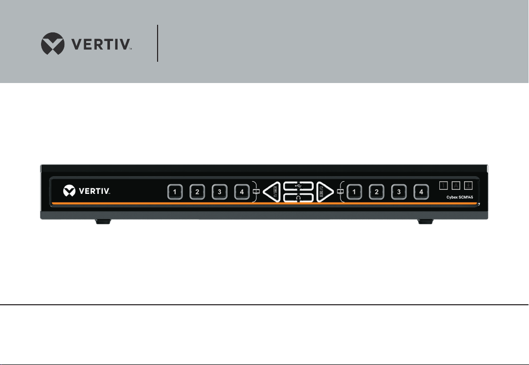
Features – Cybex SCM145/Cybex SCM145H Front Panel ......................12
Features – Cybex SCM145 Rear Panel .........................................13
Features – Cybex SCM145H Rear Panel .......................................14
Product Specifications .......................................................15
Installation........................................................... 16
Before Installation ............................................................16
Installation ...................................................................17
Typical system installation diagram Cybex SCM145/Cybex SCM145H ........ 20
Vertiv 4- Port Secure KV M Mini-Matrix
Operation ............................................................21
TROUBLESHOOTING.................................................. 25
INFORMATION ....................................................... 29
BACK TO TABLE OF CONTENTS >
1
Page 3

Table of Contents
INTRODUCTION
SECTIONS
1
2 3 4 65
Thank you for purchasing this Vertiv Secure product designed for use in secure
defense and intelligence installations. The product provides the highest security
safeguards and features that meet today’s IA (information assurance) computing
requirements as defined in the latest PSS Protec tion Profile Rev 3.0.
Secure meeting rooms or manager offices in secure organizations often have
multiple comp uters to be displayed simultaneously on desk top display and large
screen.
Vertiv mini matrixes allow users to connect multiple computers and proje ct their
outputs on 2 connected displays. Users are also able
to switch their mouse and keyboard between the connected computers.
This User Manual provides all the details you’ll need to install and operate your
new product.
Intended Audience
This document is intended for the following professionals:
• System Administrators/IT Managers
• End Users
Package Contents
Inside product packaging you will find the following:
• Vertiv Secure Product
• AC Power Cord
• User Guidance Documentation
Vertiv 4- Port Secure KV M Mini-Matrix
Important Security Note:
If you are aware of p otential security vuln erability while ins talling or operating
this product, we encourage you to contact us immediately in one of the
following ways:
• Email: Secure@VertivCo.com
• Tel: +1-888-793-8763
Important: This produc t is equipped with always-on active anti-tampering
system. Any at tempt to open the product enclosure will ac tivate the antitamper triggers and render the unit inoperable and warrant y void.
Revision
A – Initial Release, 24 Feb 2015
B – Corrections, 5 April 2015
C – Product image updates, 25 May 2015
D – User Guidance changes, 16 June 2015
E – Correction to Features sec tion, 13 August 2015
F – Changing to VERTIV branding, 15 May 2019
BACK TO TABLE OF CONTENTS >
2
Page 4

Table of Contents
SECTIONS
1 3 4 65
OVERVIEW
Safety Precautions
Please read the following safety precautions carefully before using the produc t:
• Before cleaning, disconnec t the product from any electric al power supply.
• Do not expose the product to excessive humidity or moisture.
• Do not store or use for extensive period of time in extreme thermal
conditions – it may shorten product lifetime.
• Install the product only on a clean secure surface.
• If the produc t is not used for a long period of time, disconnect it from
ele ctric al powe r.
• If any of the following situations occurs, have the product checked by a
qualified service technician:
– Liquid penetrates the product’s case.
– The product is exposed to excessive m oisture, water or any other liquid .
– The produc t is not working well even after carefully following the
instructions in this user ’s manual.
– The produc t has been dropped or is physically damaged.
– The produc t shows obvious signs of breakage or loose internal parts.
– In case of external power supply – If power supply overheats, is broken
or damaged, or has a damaged cable.
2
• The produc t should be stored and used only in temperature and humidity
controlled environments as defined in the product’s environmental
specifications.
• Never attempt to open the product enclosure. Any attempt to open the
enclosure will permanently damage the product.
• The product contains a no n-replaceable internal battery. Never attempt to
replace the bat ter y or open the enclosure.
• This produc t is equipped with always-on active anti-tampering system.
Any attempt to open the product enclosure will activate the anti-tamper
triggers and render the unit inoperable and warranty void.
Vertiv 4- Port Secure KV M Mini-Matrix
BACK TO TABLE OF CONTENTS >
3
Page 5

Table of Contents
SECTIONS
1 3 4 65
2
OVERVIEW
Safety Precautions - Précautions de sécurité (French)
Veuillez lire attentivement les précautions de sécurité suivantes avant d’utiliser
le produit:
• Avant nettoyage, débranchez l’appareil de l’alimentation DC / AC.
• Assurez-vous de ne pas exposer l’appareil à une humidité excessive.
• Assurez-vous d’installer l’appareil sur une surface sécurisée propre.
• Ne placez pas le cordon d’alimentation DC en travers d’un passage.
• Si l’appareil n’est pas utilisé de longtemps, retirez l’alimentation murale de
la prise électrique.
• L’appareil devra être rangé uniquement dans des environnements à
humidité et température contrôlées comme défini dans les caractéristiques
environnementales du produit.
• L’alimentation murale utilisée avec cet appareil devra être du modèle
fourni par le fabricant ou un équivalent certifié fourni par le fabricant ou
fournisseur de service autorisé.
• Si une des situations suivantes survenait, faites vérifier l’appareil par un
technicien de maintenance qualifié:
– En cas d’alimentation externe - L’alimentation de l’appareil surchauf fe,
est endommagée, cassée ou dégage de la fumée
– ou provoque des court circuits de la prise du secteur.
– Un liquide a pénétré dans le boîtier de l’appareil.
– L’appareil est exposé à de l’humidité excessive ou à l’eau.
– L’appareil ne fonctionne pas correctement même après avoir suivi
attentivement les instructions contenues dans ce guide de l’utilisateur.
– L’appareil est tombé ou est physiquement endommagé.
• L’appareil présente des signes évidents de pièce interne cassée ou
desserrée
• L’appareil contient une batterie interne. La batterie n’est pas remplaçable.
N’essayez jamais de remplacer la bat terie car toute tentative d’ouvrir le
boîtier de l’appareil entraînerait des dommages permanents à l’appareil.
• Ce produit est équipé d’toujours-sur le système anti-sabotage active.
Toute tentative d’ouvrir le boîtier du p roduit va activer le dé clencheur antisabotage et de rendre l’unité vide inutilisable et garantie.
Vertiv 4- Port Secure KV M Mini-Matrix
BACK TO TABLE OF CONTENTS >
4
Page 6

Table of Contents
SECTIONS
1 3 4 65
2
OVERVIEW
User Guidance & Precautions
Please read the following User Guidance & Precauti ons carefully before using the
product:
1. As product powers-up it performs a self-test procedure. In case of self- test
failure for any reas on, including jammed bu ttons, the product w ill be Inoperable.
Self-test failure will be indicated by the following abnormal LED behavior:
a. All channel-select LEDs will be turned ON and then OFF;
b. A specific, predefined LED combination will be turned ON;
c. The predefined LED combination will indicate the problem type (jammed
buttons, firmware integrity).
Try to power cycle product. If problem persists please contact your system
administrator or technical support.
2. Product power-up and RFD behavior:
a. By default, after pro duct power-up, the active channel will b e computer #1,
indicated by the applicable front panel push button LED lit.
b. Product Restore-to-Factory-Default (RFD) function is available via a
physical control button on rear panel. Use a sharp object or paper clip to
hold RFD button pressed for several seconds to initiate an RFD action.
c. RFD action will be indicated by front panel LEDs blinking all together.
d. When product boots after RFD, keyboard and mouse will be mapped to
the active channel #1 and defaul t settings will be restore d, erasing all user-
set definitions.
3. The appropriate usage of peripherals (e.g. keyboard, mouse, display,
authentication device) is described in detail in this User Manual’s appropriate
sections. Do not connect any authentication device with an ex ternal power
source to product.
4. For se curity reasons produc ts do not support wireless keyboards and mice. In
any case do not connect wireless keyboard/mouse to product.
5. For security reasons products do not support microphone/line-in audio
input. In any case do not connec t a microphone to product audio output
port, including headsets.
6. Product is equipped with always-on ac tive anti-tampering system. Any
attempt to open product enclosure will activate the anti-tamper system
indicated by all channel-select LEDs f lashing continuously. In this case,
product will be inoperable and warranty void. If produc t enclosure appears
disrupted or if all channel-select LEDs f lash continuously, please remove
product from service immediately and contact technical support.
7. In case a connected device is rejec ted in the console port group the user will
have the following visual indications:
a. When connecting a non-qualified keyboard, the keyboard will be non-
functional with no visible keyboard strokes on screen when using the
keyboard.
b. When connec ting a non-qualified mouse, the mouse will be non-
functional with mouse cursor frozen on screen.
c. When connecting a non-qualified display, the video diagnostic LED will
flash green and video will not work.
d. When conne cting a non-qualif ied USB device, DPP LED will flash gre en and
USB device will be inoperable.
8. Product has a remote control port in the back panel labeled RCU. Do not use
this port - it is inoperable and for future use.
Vertiv 4- Port Secure KV M Mini-Matrix
BACK TO TABLE OF CONTENTS >
5
Page 7

Table of Contents
SECTIONS
1 3 4 65
2
OVERVIEW
User Guidance & Precautions (Cont.)
9. Important! Before re-allocating computers to channels, it is mandatory to
power cycle product, keeping it powered OFF for more than 1 minute.
10. Product log access and administrator configuration options are described in
product Administrator Guide.
11. Authentication session will be terminated once product power is down or
user intentionally terminates session.
12. If you are aware of any potential securit y vulnerability while installing or
operating product, please remove product from service immediately and
contact us in one of the ways listed in this manual.
Vertiv 4- Port Secure KV M Mini-Matrix
BACK TO TABLE OF CONTENTS >
6
Page 8

Table of Contents
SECTIONS
1 3 4 65
2
OVERVIEW
Main Features
Product is designed, manufactured and delivered in security-controlled
environments. Below is a summar y of the main advanced features incorporated
in product:
Advanced isolation between computers and shared peripherals
The emulations of keyboard, mouse and display EDID, prevent direct contact
between computers and shared peripherals. Product design achieves maximal
securit y by keeping the video path separate with keyboard and mouse switched
together, purging keyboard buffer when switching channels. All these features
contribute to strong isolation between computer interfaces, maintained even
when produc t is powered off.
Unidirectional data flow: USB, audio and video
Unique hardware architecture components prevent unauthorized data flow,
including:
• Optical unidirectional data flow diodes in the USB data path that filtrate
and reject unqualified USB devices;
• Secure analog audio diodes that prevent audio eavesdropping with no
support for microphone or any other audio-input device;
• Video path is kept separate from all other traffic, enforcing unidirectional
native video f low. EDID emulation is done at power up and block s all
EDID/MCCS writes. For DisplayPort video, filtration of AUX channel exists
to reject unauthorized transactions.
Isolation of power domains
Complete isolation of power domains prevents signaling attacks.
Secure administrator access & log functions
Product incorporates secure administrator access and log functions to provide
auditable trail for all product security events, including battery backup life for
anti-tampering and log functions. Non-reprogrammable firmware prevents the
ability to tamper with product logic.
Always-on, active anti-tamper system
Active anti-tampering system prevents malicious insertion of hardware implant
such as wireless key-logger inside product enclosure.. Any anti-tampering
attempt causes isolation of all computers and peripheral devices rendering
product inoperable and showing clear indications of tampering event to user.
Holographic security tamper-evident labels are placed on the enclosure to
provide a clear visual indication if product has been opened or compromised.
Metal enclosure is designed to resist mechanical tampering with all
microcontrollers protected against firmware-read, modification and rewrite.
Duplicate Output Displays
The Mini Matrix allows the user to duplicate the output displays making it eas y to
project various sources in secure meeting rooms
Vertiv 4- Port Secure KV M Mini-Matrix
BACK TO TABLE OF CONTENTS >
7
Page 9

Table of Contents
OVERVIEW
Main Features (Cont.)
SECTIONS
1 3 4 65
2
DVI-I and HDMI Video Support
The Switches sup port varied video inputs of DV I-I and HDMI. DVI mod el supports
HDMI and VGA via compatible cables.
VDT Switching
VDT enables eas y switching of keyboard and m ouse by moving mouse based on
4 possible presets for monitor positioning.
Resolutions Supported
Switches support video resolutions of up to 4K-2K Ultra HD (3840 X 2160 pixels).
Audio Switching
Allows you to share speakers and headphones between computers.
Toggle Audio feature
Front panel Toggle Audio button enables to leave audio in a specific channel.
Vertiv 4- Port Secure KV M Mini-Matrix
Filtered USB (DPP) feature (applicable models)
DPP feature enables to connect authorized USB devices to produc t. Product is
designed wi th complete isolation bet ween DPP data, such as user authent ication
smart card reader data, and all other produc t traffic.
The DPP feature can be managed via Configurable Device Filtering (CDF)
mechanism with configuration permissions limited to authenticated
administrators. For more details please refer to the “DPP Configuration Manual”.
“Freeze DPP” feature
Dedicated “Freeze DPP” slider on front panel enables to lock this function to
a specific channel. When locked, switching channels will not affect processes
performed by the USB device connected to the locked channel.
BACK TO TABLE OF CONTENTS >
8
Page 10
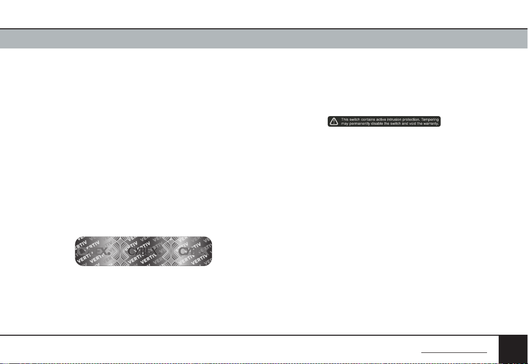
Table of Contents
OVERVIEW
SECTIONS
1 3 4 65
2
Tamper Evident Labels
Product uses holographic tamper evident labels to provide visual indications
in case of an enclosure intrusion at tempt. When opening product packaging
inspect the tampering evident labels.
Vertiv Tamper Evident Label
If for any reason one or more tamper-evident label is missing, appears
disrupted, or look s different than the example shown here, please call
Technical Support and avoid using that product.
Active Anti-Tampering System
Product is equipped with always-on active anti-tampering system. If mechanic al
intrusion is detected by this system, the Product will be permanently disabled
and all LEDs will blink continuously.
If product indicates “tampered state” (all LEDs blinking) – please call
Technical Support and avoid using that product.
Vertiv Tamper Evident Label
Vertiv 4- Port Secure KV M Mini-Matrix
Product Enclosure Warning Label
Product has the following warning sticker on a prominent location on the
product enclosure:
Vertiv Tam per Warning La bel
BACK TO TABLE OF CONTENTS >
9
Page 11

Table of Contents
SECTIONS
OVERVIEW
Equipment Requirements
1 3 4 65
2
Cables
It is highly recommended to use Vertiv Cable Kits for product to ensure optimal
security and performance.
One Cable Kit is required per connected computer.
Operating Systems
Product is compatible with devices running on the following operating systems:
• Microsoft® Windows®
• Red Hat®, Ubuntu® and other Linux® platforms
• Mac OS® X v10.3 and higher.
USB Keyboard console p ort
The produc t console USB keyboard por t is compatible with Standard USB
keyboards.
Vertiv 4- Port Secure KV M Mini-Matrix
Notes:
a. Console USB keyboard and mouse ports are switchable, i.e. you can
connect keyboard to mouse port and vice versa. However, for optimal
operation it is recommended to connect USB keyboard to console USB
keyboard port and USB mouse to console USB mouse port.
b. For securit y reasons products do not suppor t wireless keyboards. In any
case do not connect wireless keyboard to product.
c. Non-standard keyboards, such as keyboards with integrated USB hubs
and other USB-integrated devices, may not be fully supported due
to security policy. If they are suppor ted, only classical keyboard (HID)
operation will be func tional. It is recommended to use standard USB
keyboards.
BACK TO TABLE OF CONTENTS >
10
Page 12

Table of Contents
OVERVIEW
SECTIONS
1 3 4 65
2
USB Mouse console port
The produc t console USB mouse port is compatible with standard USB mice.
Notes:
a. Console USB keyboard and mouse ports are switchable, i.e. you can
connect keyboard to mouse port and vice versa. However, for optimal
operation it is recommended to connect USB keyboard to console USB
keyboard port and USB mouse to console USB mouse port.
b. Console USB mouse port supports Standard KVM Extender composite
device having a keyboard/mouse functions.
c. For security reasons product s do not support wireless mice. In any case
do not connec t wireless mouse to product.
PS/2 Mouse and Keyboard console ports
The produc t console PS/2 keyboard and mouse por ts are compatible with
standard PS/2 keyboards and mice.
Vertiv 4- Port Secure KV M Mini-Matrix
User Display
The Switch consol e video port is compati ble with the following t ypes of displays:
• Cybex SCM145 supports DVI-I displays as well as VGA and HDMI via
compatible cables.
• Cybex SCM145H supports HDMI displays.
User Audio Devices
Product is compatible with the following t ypes of user audio devices:
• Stereo headphones;
• Amplified stereo speakers.
Note: In any case do not connect a mic rophone to product audi o output port
including headsets.
BACK TO TABLE OF CONTENTS >
11
Page 13

Table of Contents
SECTIONS
1 3 4 65
OVERVIEW
Features – Cybex SCM145/Cybex SCM145H Front Panel
2
Vertiv 4- Port Secure KV M Mini-Matrix
32 541 6
1 No. 1-4 Compute r No. 1 display Push-But ton and LED 7 Num Lock LED
2 Keyboar d and Mouse toggle and LE D 8 C aps Lock LED
3 DPP Freeze tog gle and LED 9 Scroll Lock LED
4 Audio Freeze to ggle and LED 10 Tamper Evident Labels
5 Keyboar d and Mouse toggle and LE D
6 No. 1-4 Compute r No. 2 display Push-But ton and LED
7 8 9
BACK TO TABLE OF CONTENTS >
1010
12
Page 14

Table of Contents
NOTICE!
8830-16646 Rev. A00
SECTIONS
OVERVIEW
Features – Cybex SCM145 Rear Panel
1 3 4 65
2
This RCU
port has not
been certified
by Common
Criteria.
Vertiv 4- Port Secure KV M Mini-Matrix
32 4 5 6 7 1098
111
12 13 15 1614
1 DPP console ja ck 7 PS/2 Mouse Ja ck 13 User Disp lay #2 output DVI-I vid eo jack
2 DPP LED 8 Keyboar d and Mouse Input Jack - Com puter #4 14 User Displ ay #1 st atus LED
3 Remote control (non-operative, for future use) 9 Audio Inp ut Jack - Computer #4 15 User Displ ay #1 out put DVI-I video j ack
4 Audio Outp ut Jack 10 USB Jack - Compute r #4 16 No. 4 compute r display DVI-I vide o input jack
5 USB Console Key board and Mouse Jack 11 Powe r Input Jack
6 PS/2 Keybo ard Jack 12 Resto re to default
BACK TO TABLE OF CONTENTS >
13
Page 15

Table of Contents
NOTICE!
8830-16646 Rev. A00
SECTIONS
OVERVIEW
Features – Cybex SCM145H Rear Panel
1 3 4 65
2
This RCU
port has not
been certified
by Common
Criteria.
1 DPP console ja ck 7 PS/2 Mouse Ja ck 13 User Disp lay #2 output HDMI video j ack
2 DPP LED 8 Keyboar d and Mouse Input Jack - Com puter #4 14 User Displ ay #1 st atus LED
3 Remote control (non-operative, for future use) 9 Audio Inp ut Jack - Computer #4 15 User Displ ay #1 out put HDMI video jack
4 Audio Outp ut Jack 10 USB Jack - Compute r #4 16 No. 4 compute r display HDMI video inp ut jack
5 USB Console Key board and Mouse Jack 11 Powe r Input Jack
6 PS/2 Keybo ard Jack 12 Resto re to default
Vertiv 4- Port Secure KV M Mini-Matrix
32 4 5 6 7 1098
12 13 15 1614
111
BACK TO TABLE OF CONTENTS >
14
Page 16

Table of Contents
OVERVIEW
Product Specifications
SECTIONS
1 3 4 65
2
Enclosure Metal enclosure
Power Requirements 35W internal
AC Input 100 to 240VAC
No. of Sec ure Channels 4
No. of User s Supported 2
Cybex SCM145: DVI- I DIsplays (Suppor ts HDMI
Displays Supported
Resolution Support
Console Keyboard Input
Console Mouse Input
Console DPP Input USB Type A
Console D isplay Port
Console A udio Out 1/8" (3.5mm) stereo jac k
CPU Keyboard/Mouse Ports USB Type-B jack
Vertiv 4- Port Secure KV M Mini-Matrix
and VGA via com patible cables)
Cybex SCM145H: HDMI DIsplays
Cyb ex SC M145 suppor ts up to HD resolution s
(1920 X 1200 p ixels).
Cyb ex SC M145H supp orts up to 4K-2K Ultra HD
resoluti ons (3840 X 2160 pixels).
USB Type-A femal e connector or PS/2 Min i-DIN
6 pin female co nnector
USB Type-A femal e connector or PS/2 Min i-DIN
6 pin female co nnector
Cybex SCM145: 2 x DVI- I female connector s
Cybex SCM145H: 2 x HDM I female connector s
CPU DPP Por ts USB Type-B jack
CPU Audio In put 1/8" (3.5mm) stereo jac k
Front Panel indicators
CPU Vide o Input Port
Operating Temp 32° to 104° F (0° to 40 ° C)
Storage Temp -4° to 140° F (-20° to 60° C )
Humidity 0-80% RH, non-condensing
Warranty 2 years
Product design life-cycle 10 year s
CAPS LOCK, N UM LO CK, SCL LOCK
Freeze audio a nd Freeze DPP controls
Cybex SCM145: DVI- I female connecto r
Cyb ex SC M145H: HDMI female connec tor
BACK TO TABLE OF CONTENTS >
15
Page 17

Table of Contents
INSTALLATION
Before Installation
SECTIONS
1 2 4 65
3
Unpacking the Product
Before opening the product packaging, inspect the packaging condition to
assure that product was not damaged during delivery.
When opening the package, inspec t that the product Tamper Evident Labels are
intact.
Important:
1. If the unit’s enclosure appears disrupted or if all channel-select LEDs
flash continuously, please remove product from service immediately and
contact Technical Support at: http://www.VertivCo.com
2. Do not connect product to computing devices:
a. That are TEMPEST computers;
b. That include telecommunication equipment;
c. That include frame grabber video cards
d. That include special audio processing cards.
Vertiv 4- Port Secure KV M Mini-Matrix
Where to locate the Pro duct?
The enclosure of the produc t is designed for desktop or under the table
configurations. An optional Mount Kit is available.
Product must be located in a secure and well protected environment to prevent
potential at tacker access.
Consider the following when deciding where to place product:
• Product front panel must be visible to the user at all times.
• The location of the computers in relation to the product and the length of
available cables (typically 1.8 m)
Warning: Avoid placing cables near fluorescent lights, air-conditioning
equipment, RF equipment or machines that create electrical noise (e.g.,
vacuum cleaners).
BACK TO TABLE OF CONTENTS >
16
Page 18

Table of Contents
INSTALLATION
Installation
SECTIONS
1 2 4 65
3
Step 1 – Connecting devices to product console
Product re quires connection of all d evices and computers prior to p owering it up.
Note: some devices such as user display would not be recognized if
connected after product is already powered up.
See figures above for connector locations.
• Connect us er display. Mark which display is coupled wi th which computer.
It is also recommended to mark which computer is coupled with which
channel.
• Connect us er keyboard and mouse to console keyboard an d mouse ports.
• Connect headphones/speakers to console audio out port (optional).
• If the computer uses a smart card reader/USB device, connec t the smart
card reader/USB device to the console DPP p ort (optional, model p ending).
Vertiv 4- Port Secure KV M Mini-Matrix
Notes:
1. Console USB keyboard and mouse por ts are switchable, i.e. you can
connect keyboard to mouse port and vice versa. However, for optimal
operation it is recommended to connect USB keyboard to console USB
keyboard port and USB mouse to console USB mouse port.
2. For security reasons produc ts do not support wireless keyboards. In any
case do not connect wireless keyboard to product.
3. Non -standard keyboards, su ch as keyboards with integrate d USB hubs and
other USB-integrated devices, may not be fully supported due to security
policy. If the y are supported, only classical keybo ard (HID) operation will be
functional. It is recommended to use standard USB keyboards.
4. Console USB mouse por t suppor ts Standard K VM Extender composite
device having a keyboard/mouse functions.
BACK TO TABLE OF CONTENTS >
17
Page 19

Table of Contents
INSTALLATION
SECTIONS
1 2 4 65
3
Step 2 – Connecting the Computers
• Using USB cables, connect each computer to the USB type B port in
“computer interface ports” area on product.
• If computer uses audio output, e.g. speakers/headphones, connect audio
cable from its audio output port to the corresponding audio input port
on product.
• If the computer uses a smart card reader/USB device, connect a USB cable
between the DPP-enabled computer and the corresponding DPP port on
product.
Note:
1. If the number of product channels is larger than the number of sources
used, make sure the computers are connected in a row starting from
computer #1. For example, if there are 3 channels used, con nect computers
to channels #1, #2 and then #3.
2. The USB cable must be connected directly to a free USB port on the
computer, with no USB hubs or other devices in between.
Vertiv 4- Port Secure KV M Mini-Matrix
Step 3 – Power up
• Connect AC power cord.
• Power up user display/s. Select through display setup menu the
appropriate video input if applicable.
• Power up the connected computers.
• Power up the product.
When you power up your computers, the product emulates display, mouse
and keyboard on each port and allows your computers to boot normally. You
should be able to move the mouse cursor on the primary display connected to
computer #1.
Check to see that the keyboard and mouse are working properly on each
computer.
Repeat this check with all occupied ports to verif y that all computers are
connected and responding correctly.
If you encounter an error, check your cable connections for that computer and
reboot. If the problem persists, please refer to the Troubleshooting section in
this User Manual.
BACK TO TABLE OF CONTENTS >
18
Page 20

Table of Contents
INSTALLATION
SECTIONS
1 2 4 65
3
Step 4 – DPP Installation (applicable models)
In case computer and product support DPP functionality, such as user
authentication smart card reader, do the following:
1. Connect USB device, such as smart card reader, to DPP port on product
console
2. Connect DPP input port on product to any free USB port on computer using
a USB cable.Note: Do not connect the USB cable if DPP functionality is not
needed for that computer.
If only some o f the computers use DPP functionalit y, such as use r authentication,
make sure that computer #1 is connected to the USB device. If needed, switch
channels/computer mapping to create this configuration.
When produc t is powered ON and connected USB device is qualified and ready
for use, the DPP status LED will illuminate steady green.
In case the conn ected USB device cannot be detected by th e secure product, the
DPP status LED will not illuminate at all.
The USB device will be detected only if it is fully compliant with USB 1.1 or USB
2.0 standard and is included in the list of recognized USB devices defined by the
administrator when configuring DPP functionality.
Vertiv 4- Port Secure KV M Mini-Matrix
Possible reasons for USB device not being detected:
• Non-standard USB device
• Device only operating in USB 3.0 mode
• Failed USB Device
In this case you will have to use a different USB device.
If the device is detected but is not authorized, the device will be rejected for
securit y reasons. This will be indicated by DPP status LED flashing green.
Smart card readers and CACs are included in the authorized USB devices list by
default.
BACK TO TABLE OF CONTENTS >
19
Page 21

Table of Contents
SECTIONS
1 2 4 65
INSTALLATION
Typical system installation diagram Cybex SCM145/Cybex SCM145H
Secondary Display
Computers
DPP
3
Primary Display
Audio
Mouse
Keyboard
Vertiv 4- Port Secure KV M Mini-Matrix
BACK TO TABLE OF CONTENTS >
20
Page 22

Table of Contents
SECTIONS
1 2 3 65
OPERATION
Operation
Now that you have connected your console and computers to the MiniMatrix, it is ready for use. By default computer #1 is projected on display #1 and
computer #2 is projec ted on display 2. Keyboard, mouse and audio are mapped
to computer #1.
To change the projec ted display you can use the physical push buttons.
Note: The Secure KVM Mini-Matrix does not have a power switch. It is highly
recommended that the product will be powered continuously.
Note: Keyboard, Mouse and Audio will always be mapped to one of the
projecte d channels. If it was mappe d to a channel which is no longer disp layed
it will automatically be switched to the lowest channel # currently projec ted.
For example, if channel 1 and 2 are projected and mouse and keyboard are
mapped to channel 2. Once the user will choose to project channel 1 instead
of channel 2, mouse and keyboard will automatic ally be mapped to channel 1.
To change the mapping of the keyboard, mouse and audio between active
channels use the push buttons on the switch.
Notes:
1. Keyboard shortcut keys are to be pressed sequentially
2. CTRL key refers to LEFT C TRL key.
`~1!2@3#4$5%6^7&8*9(0)-_=
Tab
Q W E R T Y U I O P
Caps
A S D F G H J K L
Shift
Z X C V B N M
CtrlCtrl Alt Alt
+
Delete
}
[{]
:
“
;
‘
?/>.<
,
Page
Num
Insert
Home
=
/
UP
Lock
|
Page
Delete
End
Down
\
Enter
é
Shift
Ctrl
ç ê è
7 8 9
4 5 6
1 2 3
0
*
-
+
Enter
,
4
Operating the KVM Switch
1. Self-Test Procedure:
As produc t powers-up it performs a self-test procedure. In cas e of self- test failure
for any reason, including jammed buttons, the product will be Inoperable. Selftest failure will be indicated by the following abnormal LED behavior:
• All channel-select LEDs will be turned ON and then OFF;
• A specific, predefined LED combination will be turned ON;
• The predefined LED combination will indicate the problem type (jammed
buttons, firmware integrity).
Try to power cycle product. If problem persists please contact your system
administrator or technical support.
Now that produc t, computers and peripherals are connected and powered up,
it is ready for use.
2. Default Channel
After product boots up, blue LEDs stripe will illuminate and the default active
channel will be channel #1. This will be indicated by white color illumination of
push-but ton #1.
Vertiv 4- Port Secure KV M Mini-Matrix
BACK TO TABLE OF CONTENTS >
21
Page 23

Table of Contents
OPERATION
SECTIONS
1 2 3 65
4
3. Product M apping to Sources
Product mapping to sources is indicated by stickers/labels specif ying which
channel is mapped to which computer.
4. Front Panel Push-Buttons
Following power up, the default channel is #1.
The user can select any other channel by pressing the appropriate front panel
push button.
The mouse cursor will be positioned at the center of the selected computer
display. If computer is connected to multiple displays, the cursor will be
positioned at the center of the primary display.
The currently selected channel is indicated by white color illumination of the
appropriate push-button.
Once a different channel is selected – video, keyboard, mouse, audio and
DPP functions follow selected channel, unless Freeze DPP function has been
activated (see below for details).
5. DPP Port (applicable models)
The produc t is equipped with DPP port enabling connectivity to external USBdevices such as smartcard reader.
The filtered USB function (DPP) enables to control which USB devices will be
operative when connected to produc t.
For more details on configuration options, p lease refer to the “DPP Configuration
Manual”.
Vertiv 4- Port Secure KV M Mini-Matrix
Summary of rules that apply to DPP switching:
It is assumed that a “connected channel” is when:
1. Product is powered ON
2. The USB device connec ted to produc t console is qualified and ready for use,
as indicated by the DPP status LED illuminating steady green.
3. The channel DPP port on product is connected via USB cable to a USB port
on computer.
• When the USB device connected to the DPP console port is qualified, the
DPP status LED on the front panel would illuminate steady green.
– When connecting a USB device that is not qualified or rejec ted for
securit y reasons to the product ’s DPP port, the DPP LED will f lash green
and USB device will b e inoperable. In such case the USB device must b e
replaced with a qualified device.
– When connecting a USB device to the product’s DPP por t that is
undetec table for any reason (e.g. faile d device, non-standard d evice etc.),
the DPP LED will not illuminate at all and USB device will be inoperable.
In such case the USB device must be replaced with a qualified device.
• Since channel #1 is the default active channel after power up and in case
only some of the channels operate with a USB device, it is recommended
to make sure computer #1 is connec ted to USB device.
• Once the user switches channels, for example to channel #3, DPP
functionality will move to computer #3 and be indicated by channel #3
DPP LED turning steady green.
• In case user switches to a channel that is not connec ted to a USB device,
the previous USB connection will be terminated and no new connection
will be established.
BACK TO TABLE OF CONTENTS >
22
Page 24

Table of Contents
OPERATION
SECTIONS
1 2 3 65
4
• In case “Freeze DPP” slider was moved to activate DPP function for
computer #1, for example, switching to a different channel would keep
DPP function locked to channel #1. To release “Freeze DPP” function from
channel #1, the user will need to move the “Freeze DPP” slider again to its
original position. The release will be indicated by the channel #1 DPP LED
being turned off.
• In case Restore-to-Default was performed while “Freeze DPP” slider was
activated on a specific channel, af ter boot up this function will be locked
to computer #1.
6. Using “DPP Freeze” feature
Move the “DPP Freeze” slider to lock DPP function to a specific channel. The DPP
status LED will indicate that this option has been a ctivated and to which channel
the DPP func tion is locked to at the moment . This means that switching channels
would not affect the processes performed by the USB device connected to that
channel.
7. Using “Audio Freeze” feature
Press audio toggle button to lock Audio func tion to a specific channel. The LED
will indicate this option has been activated and to which channel the Audio is
locked to at the moment. This means that switching channels would leave Audio
active on current channel.
Vertiv 4- Port Secure KV M Mini-Matrix
8. Keyboard Status Indication
In order to enhance usability, product provides keyboard status indications
via dedicated LEDs located on product front panel. To maintain the required
unidirectional connectivit y between keybo ard and product, these indication are
not given on the keyboard itself as done with non-secure produc ts
The keyboard status indications are given via 3 LEDs on the front panel of the
product:
• CL – CAPS Lock
• SL – SCROLL Lock
• NL – NUM Lock
The indications behave the same as the LEDs on the keyboard as if it was
connected directly to computer.
Switching from channel to channel may change the status of the LEDs based on
the current set tings on the computer connec ted to the active channel.
BACK TO TABLE OF CONTENTS >
23
Page 25

Table of Contents
SECTIONS
1 2 3 65
OPERATION
9. VDT
It is also possible to switch mouse and keyboard between active channels using
mouse movement. Dragging the mouse curser from one display to another will
make the curser disappear from source display (computer) and appear in target
display (computer) in exactly the same relative location.
By default VDT is disabled. To enable or disable VDT use the following key
combination:
CTRL , CTRL, F11, v
Once enabled it is essential that the displays are positioned in a correct way. The
following presets exist on the Mini-matrix:
CTRL , CTRL, F11, f (default)
1 2
CTRL , CTRL, F11, f
2
1
4
Vertiv 4- Port Secure KV M Mini-Matrix
BACK TO TABLE OF CONTENTS >
24
Page 26

Table of Contents
SECTIONS
TROUBLESHOOTING
Troubleshooting Guide
1 2 3 4 6
5
Important Security Note:
If you are aware of p otential security vuln erability while ins talling or operating
this product, we encourage you to contact us immediately in one of the
following ways:
• Email: Secure@VertivCo.com
• Tel: +1-888-793-8763
Important: If the unit’s enclosure appears disrupted or if all LEDs flash
continuously, please remove product from service immediately and contact
Technical Suppor t at www.VertivCo.com
Important: This produc t is equipped with always-on active anti-tampering
system. Any at tempt to open the product enclosure will ac tivate the antitamper triggers and render the unit inoperable and warrant y void.
Vertiv 4- Port Secure KV M Mini-Matrix
General
As produ ct powers-up al l channel-sel ect LEDs are turn ed ON and then OFF.
After that a specif ic, predefined LED combination is turned ON. Product is
inoperable.
• The produc t did not pass self-test pro ce dure. Tr y to p ower cycle product. I f
problem persists pleas e contact your system ad ministrator or our technical
support.
No power - No v ideo output, non e of the front panel L EDs are illuminati ng.
• Check AC power cable connection to make sure product receives power
properly. Replace cable if ne eded. If problem persists, contac t your system
administrator or our technical support.
Product enclosure appears disrupted or all channel-select LEDs flash
continuously.
• The produc t may have been tampered with. Please remove product from
service immediately and contact Technical Support.
BACK TO TABLE OF CONTENTS >
25
Page 27

Table of Contents
SECTIONS
TROUBLESHOOTING
1 2 3 4 6
5
Keyboard
Mouse and keyboard are not working (two channels)
• Check that computer USB and video cables are not crossed i.e. computer
#1 video is connec ted to channel #1 while USB keyboard and mous e cables
are connected to channel #2.
Keyboard does not work (all channels)
• Check that the keyboard you are using is properly connected to product.
• Check that the USB cable between the product and computer is properly
connected.
• Try connecting keyboard to a different USB port on computer.
• Make sure the keyboard works when direc tly connected to computer, i.e.
the HID USB driver is installed on computer; this may require computer
reboot.
• It is recommended to use standard USB keyboards and not a keyboard
with an integrated USB hub or other USB-integrated devices.
• If the computer is coming out of standby mode, allow up to one minute
to regain mouse function.
• Try a different keyboard.
• Do not use a wireless keyboard.
Vertiv 4- Port Secure KV M Mini-Matrix
Mouse
Mouse and keyboard are not working (two channels)
• Check that computer USB and video cables are not crossed i.e. computer
#1 video is connec ted to channel #1 while USB keyboard and mous e cables
are connected to channel #2.
Mouse does not work (all channels)
• Check that the mouse you are using is properly connected to product.
• Check that USB cable between the produc t and computer is properly
connected.
• Try connecting mouse to a dif ferent USB port on computer.
• Make sure the mouse works when directly connecte d to computer, i.e. the
HID USB driver is installed on computer; this may require computer reboot.
• It is recommended to use standard USB mice.
• If the computer is coming out of standby mode, allow up to one minute
to regain mouse function.
• Try a different mouse.
• Do not use a wireless mouse.
Both keyboard and mouse are not working (one channel)
• Use computer Device Manager Utility to see product and solve problem.
BACK TO TABLE OF CONTENTS >
26
Page 28

Table of Contents
SECTIONS
TROUBLESHOOTING
Video
1 2 3 4 6
5
No video image in user display (all channels)
• Check that displays are properly powered.
• Check that video cable is properly secured at both sides.
• Check at the displays’ on-screen menu that sources selected match the
cables connected to displays.
• Check if display video mode is the same as computer’s video mode (e.g.
DVI and DVI, etc.).
• Check that displays’ diagnostic LED is steady green – if not, change
displays, change displays’ cables or call technical support.
No video image in user display (specific channel)
• Reboot product first, then disconnect and reconnect the video cable and
reboot the computer.
• Check that the video cable connecting computer and product is properly
secured at both sides.
• Check that computer video output is sent to the connected video
connector (if computer supports multiple displays).
• Check that computer resolution matches connected display capabilities.
• Connect the display/s directly to the computer to confirm that video
output is available and that a good image is shown.
Vertiv 4- Port Secure KV M Mini-Matrix
Bad video image quality (some or all channels)
• Check that all video cables are properly connected to product, computer,
and display.
• Check that cables are original cables supplied by Vertiv.
• With everything connected, power-cycle the product to reset the video.
Make sure the Video Diagnostic LED is solid green.
• Check that the displays that you are using support the resolution and
refresh-rate setting on computer.
• Lower the video resolution of your computer.
• Connect displays directly to computer showing bad video image to see if
problem persists.
BACK TO TABLE OF CONTENTS >
27
Page 29

Table of Contents
SECTIONS
1 2 3 4 6
TROUBLESHOOTING
DPP
DPP is not working (two channels)
• Check that computer USB and video cables are not crossed i.e. computer
#1 video is connected to channel #1 while USB device is connected to
channel #2.
DPP is not working (all channels)
• Check that the USB device is properly connected to product console.
• Check that the DPP status LED is steady green. If DPP status LED is not
illuminated at all the device is not recognized by the product. If DPP
status LED is flashing green device is rejected or non- qualified for security
reasons. To resolve please contact your system administrator.
DPP is not working (one channel only)
• Check that device is working properly when connected directly to
computer.
• Check that there is a USB cable connec ted between the compu ter and the
relevant DPP input port on product.
5
Vertiv 4- Port Secure KV M Mini-Matrix
BACK TO TABLE OF CONTENTS >
28
Page 30

Table of Contents
SECTIONS
1 2 3 4 65
INFORMATION
COPYRIGHT AND LEGAL NOTICE
Vertiv, Vertiv Network Power and the Vertiv Network Power logo are trademarks
or service marks of Ver tiv Electric
Co. Avocent and the Avocent logo are trademarks or ser vice marks of Avocent
Corporation. This document may contain confidential and/or proprietary
information of Avocent Corporation, and its receipt or possession does not
convey any right to reproduce, disclose its contents, or to manufacture or sell
anything that it may describe. Reproduc tion, disclosure, or use without specific
authorization from Avocent Corporation is strictly prohibited.
©2015 Avocent Corporation. All rights reser ved.
The information and specifications in this document are subject to change
without prior notice.
Images are for demonstration purposes only.
6
Vertiv 4- Port Secure KV M Mini-Matrix
BACK TO TABLE OF CONTENTS >
29
Page 31

© 2015 All rights reser ved.
 Loading...