

Page 1
LIEBERT® RDUA G2
Intelligent Monitoring Solution
FEATURES
The Liebert® RDU-A G2 allows
data center managers to perform
the following operations through
a secure web page:
Monitoring of the health and
status of the equipment
Monitoring of environmental
conditions i.e. temperature
and humidity, leak and smoke.
Monitor the improved
communication speed in
transmitting control or
commands to the equipment
and parameter setting
Records Data and Logs of
historical information of
alarms and notifications
3rd Party Communications:
SNMP
The Liebert® RDU-A G2 is an infrastructure management
solution from Vertiv that allows data center administrators to
manage environmental conditions i.e. temperature and
humidity, leak, smoke, vibrations and digital inputs and
outputs. It is also capable of monitoring infrastructure
appliances such as UPS, precision cooling units, generator
sets and etc. The Liebert® RDU-A G2 is equipped with a
built-in web server, eliminating the need to perform a
software installation.
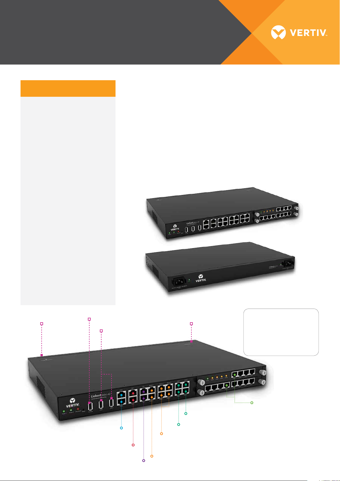
FRONT
Modbus 485
Dry contacts
Analog Signals
Power Input 1
100 ~ 240VAC
Console Port USB
USB Camera /
Modem Port
Network Port 1 and 2
10/100Mbps
Relay Output 1 and 2
+12Vdc @ 0.2A
Digital Input 1 and 2
+12Vdc @ 0.1A
Power Input 2
100 ~ 240VAC
COM Port 3 (2 ports)
COM Port 1, 2
Sensor Port 1 (2 ports)
Sensor Port 2 (2 ports)
+12Vdc @ 0.2A
Smoke Sensor Port 1 and 2
+12Vdc @ 0.1A
BACK
LEGEND:
Modbus 485 Com Port
Environmental Sensor Port
Contact Closure Output Port
Ethernet and SNMP Port
2 Slots for optional
4COM Port Card / 8DIAI
Card / 8DOAO Card
Page 2
LIEBERT® RDUA G2
The Liebert® RDU-A G2 serves as the communication gateway for the equipment and the Liebert® RDU-M solution. It
intelligently collects and communicates data and commands, giving IT administrators a comprehensive view of what’s
happening at the equipment level of the facility.
Infrastructure Management
1. Modbus 485 and/or SNMP
Communications
i. Default of 16 devices in an
RDU module (Can be all
Modbus 485, or all SNMP, or
a Mix).
ii. Can be extended to have
additional 16 devices more
by purchasing licenses to
make the total to a maximum
of 32.
iii. Each COM port can support a
maximum of 4 daisy chained
connection (need to be same
device) BUT maximum Per
device will still be 32 devices.
Note: If communicating to a 3rd part
will need to get SNMP MIB File for SNMP
communication and Modbus Reference Library
for Modbus communication to build driver. This
will incur additional charges.
y device,
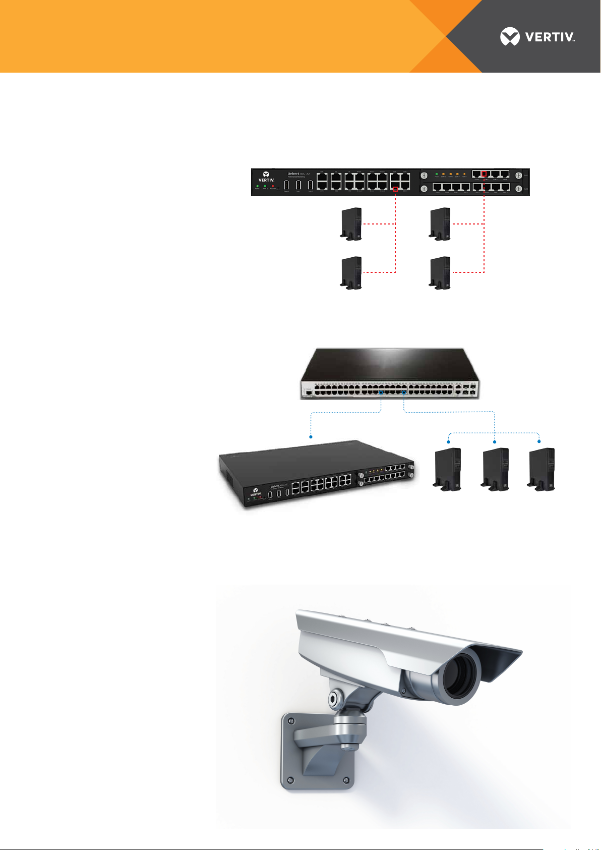
Modbus 485 Communications
485 Daisy Chain
High Level Modbus 485
Communications
High Level Modbus 485
Communications
SNMP Communications
Network Cable Network Cable
485 Daisy Chain
3rd Party
Network Switch
Video
surveillance
1. Directly connect 1 x IP Camera
2. Connect 4 x IP Cameras via NVR
RDU-A G2 Module
Page 3

LIEBERT® RDUA G2
Environmental:
1. Temp and Temp/Hum Sensor
i. By default (without the optional
THUB) it can support up to 32
sensors
ii. When THUB is connected, total
maximum will be 80 sensors
iii. Sensor Port 1 can only support
Temp and/or Temp/Humid Sensor
(max 16)
iv. Sensor port 2 supports 16 knots.
When 2 x 4DIF sensors are
connected with all of the ports
used, this will be considered as 10
knots (2x4DIF + 8 Sensors), the
remaining 6 knots can be used for
T /TH sensors.
Note: Each knot is considered to be 1 Sensor
EXCEPT for the Smoke and Infrared Sensors which is
considered to be 4 knots each.
Temperature Sensor
Temperature Sensor
4DI Modular Extension
(For sensor port 2)
Standard RJ45 Straight through patch cable
Leak
InfraredSmoke
Door
2. Digital Input Sensor (Door Sensor, Water Leak Sensor, Smoke Sensor, Motion Sensor, Vibration Sensor)
i. By default (without the optional 8DIAI Extension card) it can support up to 12
(8 of the 12 will be coming from 4DI sensor connected to the Sensor Port).
ii. When 2 pieces of 8DIAI cards are connected, maximum of 28 Digital Input Sensors
3. Analog Input Sensor
i. Maximum of 16 inputs using 2 pieces of 8DIAI optional card
4. Analog Output
i. Maximum of 16 outputs using 2 pieces of 8DOAO card
5 .Digital Output
i. Maximum of 18 (2 default digital output + 16 from 2 pieces of 8DOAO card)
Note: When using Smoke and Infrared Sensors, it is considered to be 4 knots each or an equivalent of 4 sensors each.
Environmental: RDU-THUB
RDU-A Generation 2
Can connect to any RS485 port of RDU-A G2
1. 16 Sensor port extension hub
i. Each sensor can have up to a
Standard RJ45 Straight through patch cable
maximum of 3 sensors each.
ii. Each of the sensor ports can
RDU-THUB
only accept Temperature and/or
Temperature/Humidity sensors
(This cannot accept DI sensors or
Standard RJ45 Straight through patch cable
any 4DI/4DIF)
iii. Maximum of 48 sensors in 1
RDU-THUB. Total maximum when
connected to the RDU-A G2 will
be 80 sensors (32 on RDU-A G2 +
48 on RDU-THUB)
iv. 1 RDU-A G2 can only support 1
RDU-THUB
Page 4

LIEBERT® RDUA G2
Mechanical Specifications
External model Measurement Valve Error
Height 43mm <±0.5 mm
RDU-A G2
Width 440mm <±1 mm
Depth 311mm <±1 mm
Weight <8kg
Height 20mm <±0.5 mm
IRM-4COM
Width 158mm <±1 mm
IRM-8DIAI
IRM-8DOAO
Depth 199mm <±1 mm
Weight <1kg
Environment Conditions
Item Requirement
Application location Usually in data center or computer room, with air conditioner
Working temperature -10ºC ~ +60ºC
Relative humidity 5%RH ~ 95%RH, no condensing
Working environment
Air pressure 70kpa ~ 106kpa
Storage temperature -40ºC ~ +70ºC
Cooling Natural cooling
Dust: compliant with the indoor requirements of GR-63. No corrosive gas, flammable gas, oily mist, steam,
water drops or salt
Power distribution
network
TT/TN
Protection level IP20
Performance Specifications
Ports Cable standard Distance (unit: m)
SENSOR1 Standard category 4 twisted-pair cable ≤ 100
SENSOR2 Standard category 4 twisted-pair cable ≤ 100
DI ports Standard category 4 twisted-pair cable ≤ 100
DO ports Standard category 4 twisted-pair cable ≤ 100
COM ports Standard category 4 twisted-pair cable ≤ 100
Product Certificate: RDU-A G2 satisfies CE allege.
VertivCo.com
© 2017 Vertiv C o. All rights reser ved. Vertiv, the Vertiv lo go are trademarks or re gistered tradem arks of Vertiv Co. All othe r names and logos r eferred to are trade na mes, trademarks o r registered trade marks of their respe ctive owners. Whi le every
precauti on has been taken to en sure accuracy and c ompleteness he rein, Vertiv Co. as sumes no respons ibility, and discla ims all liability, for d amages resultin g from use of this informa tion or for any errors or o missions. Spe cifications are s ubject to change
without notice.
Vertiv-Liebert®RDU-AG2-DS-EN-Asia-V1
 Loading...