

Page 1

NetSure™ IPE Series
Rectifier
Installation and User Manual
Specification Number: 561664, 561665, 561666
Model Number: R48-1000C
Page 2

Vertiv™ NetSure™ IPE Series Rectifier Installation and User Manual
The information contained in this document is subject to change without
notice and may not be suitable for all applications. While every precaution has
been taken to ensure the accuracy and completeness of this document, Vertiv
assumes no responsibility and disclaims all liability for damages resulting from
use of this information or for any errors or omissions. Refer to other local
practices or building codes as applicable for the correct methods, tools, and
materials to be used in performing procedures not specifically described in
this document.
The products covered by this instruction manual are manufactured and/or
sold by Vertiv. This document is the property of Vertiv and contains
confidential and proprietary information owned by Vertiv. Any copying, use or
disclosure of it without the written permission of Vertiv is strictly prohibited.
Names of companies and products are trademarks or registered trademarks of
the respective companies. Any questions regarding usage of trademark
names should be directed to the original manufacturer.
Technical Support Site
If you encounter any installation or operational issues with your product, check the pertinent section of this
manual to see if the issue can be resolved by following outlined procedures.
Visit https://www.vertiv.com/en-us/support/ for additional assistance.
Vertiv™ NetSure™ IPE Series Rectifier Installation and User Manual
Page 3

Vertiv™ NetSure™ IPE Series Rectifier Installation and User Manual
iii
TABLE OF CONTENTS
Admonishments Used in this Document .......................................................................................................................... v
Important Safety Instructions ............................................................................................................................................ vi
Static Warning ....................................................................................................................................................................... viii
1 Introduction ......................................................................................................................................................................... 1
1.1 Ordering Structure ........................................................................................................................................................................................................................................................ 1
1.1.1 Configurations ............................................................................................................................................................................................................................................ 1
1.1.2 Circuit breaker option ......................................................................................................................................................................................................................... 1
1.1.3 GMT fuse option ....................................................................................................................................................................................................................................... 1
1.1.4 What is in the box ................................................................................................................................................................................................................................... 2
1.1.5 Replacement components ............................................................................................................................................................................................................. 3
1.2 Rectifier Overview ........................................................................................................................................................................................................................................................ 4
1.3 Rectifier Specifications ............................................................................................................................................................................................................................................ 4
1.3.1 DC output ratings ................................................................................................................................................................................................................................... 4
1.3.2 AC input ratings ....................................................................................................................................................................................................................................... 6
1.3.3 Environmental ratings ..................................................................................................................................................................................................................... 10
1.3.4 Compliance information
1.3.5 Standard features ................................................................................................................................................................................................................................. 11
1.3.6 Mechanical specifications ............................................................................................................................................................................................................ 12
2 Installation ......................................................................................................................................................................... 14
2.1 General Requirements ........................................................................................................................................................................................................................................... 14
2.2 Tools and Test Equipment Required for Installation ................................................................................................................................................................ 14
2.3 Installing the Rectifier .............................................................................................................................................................................................................................................15
2.3.1 General ...........................................................................................................................................................................................................................................................15
2.3.2 Front door ....................................................................................................................................................................................................................................................15
2.3.3
Pole installation
2.3.4 Wall installation procedure
2.4 Installing GMT Fuses (P/N 561666 [R48-1000C-6] Only) ................................................................................................................................................. 20
3 Making Electrical Connections ................................................................................................................................... 20
3.1 Important Safety Instructions ........................................................................................................................................................................................................................ 20
3.2 Wiring Considerations........................................................................................................................................................................................................................................... 20
3.3 Frame Ground Connection ............................................................................................................................................................................................................................... 20
3.4 Customer Wiring to the Mating Connectors ..................................................................................................................................................................................... 21
3.5 Electrical Connections Diagrams ................................................................................................................................................................................................................26
3.6 External Alarm and Control Connections ........................................................................................................................................................................................... 30
3.6.1 General ......................................................................................................................................................................................................................................................... 30
3.6.2 Alarm and Control Connections ........................................................................................................................................................................................... 30
3.6.3 Changing the Alarm Relay Configuration for the Rectifier Fail Alarm and AC Fail Alarm ................................................ 31
3.7 Nominal 120 VAC / 208 VAC / 220 VAC / 230 VAC / 240 VAC Input and AC Input Equipment Grounding
Connections .................................................................................................................................................................................................................................................................... 32
3.8 -48 VDC Output Connections ........................................................................................................................................................................................................................ 32
3.9 -48 VDC Input Connections ............................................................................................................................................................................................................................. 32
3.10 Paralleling Rectifiers ................................................................................................................................................................................................................................................ 32
............................................................................................................................................................................................................... 10
proc
edure
........................................................................................................................................................................................................15
........................................................................................................................................................................................................ 18
Page 4

Vertiv™ NetSure™ IPE Series Rectifier Installation and User Manual
iv
3.10.1 Two Paralleled Rectifiers or One Plus One with Redundancy ................................................................................................................... 32
3.10.2 Three Paralleled Rectifiers or Two Plus One with Redundancy ............................................................................................................. 34
3.11 Final Step ........................................................................................................................................................................................................................................................................... 35
4 Initially Starting and Checking Rectifier Operation ............................................................................................. 36
4.1 Initially Starting the Rectifier .......................................................................................................................................................................................................................... 36
4.2 Checking System Status .................................................................................................................................................................................................................................... 36
5 Operation ........................................................................................................................................................................... 37
5.1 Local Indicators ........................................................................................................................................................................................................................................................... 37
5.2 Rectifier High Voltage Shutdown and Lockout Restart ........................................................................................................................................................ 37
6 Troubleshooting and Repair ........................................................................................................................................ 38
6.1 Contact Information .................................................................................................................................................................................................................................................38
6.2 Troubleshooting ..........................................................................................................................................................................................................................................................38
6.3 Repair ...............................................................................................................................................................................................................................................................................38
7 DC Power, Outdoor Enclosure & Service Contacts ............................................................................................. 40
Page 5
Vertiv™ NetSure™ IPE Series Rectifier Installation and User Manual
v
DANGER!
in death or serious injury if not avoided. (ANSI, OSHA)
WARNING!
result in
death or serious injury if not avoided. This admonition is not used for situations that pose a
risk only to equipment, software, data, or service. (ANSI)
CAUTION!
result in minor or moderate injury if not avoided. (ANSI, OSHA) This admonition is not
used for situations that pose a risk only to equipment, data, or service, even if such use
appears to
ALERT!
equipment, software, data, or service. (ISO)
ALERT!
equipment damage, software corruption, data loss, or service interruption. (ISO)
FIRE SAFETY!
or policies, or of the locations of fire
SAFETY!
policies not related to a particular source of hazard or to fire safety. (ISO, ANSI, OSHA)
Admonishments Used in this Document
Warns of a hazard the reader
Warns of a potential hazard the reader
Warns of a potential hazard the reader
be permitted in some of the applicable standards. (OSHA)
Alerts the reader to an action that
will
be exposed to that will
may
be exposed to that
may
be exposed to that
must be avoided
likely
result
could
could
in order to protect
Alerts the reader to an action that
Informs the reader of fire safety information, reminders, precautions,
Informs the reader of general safety information, reminders, precautions, or
-fighting and fire-safety equipment. (ISO)
must be performed
in order to prevent
Page 6

Vertiv™ NetSure™ IPE Series Rectifier Installation and User Manual
vi
Important Safety Instructions
Safety Admonishments Definitions
Definitions of the safety admonishments used in this document are listed under “Admonishments Used in this Document” on page v.
General Safety
DANGER! YOU MUST FOLLOW APPROVED SAFETY PROCEDURES.
Performing the following procedures may expose you to hazards. These procedures should be performed by qualified
technicians familiar with the hazards associated with this type of equipment. These hazards may include shock, energy,
and/or burns. To avoid these hazards:
a) The tasks should be performed in the order indicated.
b) Remove watches, rings, and other metal objects.
c) Prior to contacting any uninsulated surface or termination, use a voltmeter to verify that no voltage or the expected
voltage is present. Check for voltage with both AC and DC voltmeters prior to making contact.
d) Wear eye protection.
e) Use certified and well maintained insulated tools. Use double insulated tools appropriately rated for the work to be
performed.
Voltages
AC Input Voltages
DANGER! This system operates from AC input voltage capable of producing fatal electrical shock. AC input power must be
completely disconnected from the branch circuits wiring used to provide power to the system before any AC electrical
connections are made. Follow local lockout/tagout procedures to ensure upstream branch circuit breakers remain de-
energized during installation. DO NOT apply AC input power to the system until all electrical connections have been
completed and checked.
DC Output and Battery Voltages
DANGER! This system produces DC power and may have a battery source connected to it. Although the DC voltage is not
hazardously high, the rectifiers and/or battery can deliver large amounts of current. Exercise extreme caution not to
inadvertently contact or have any tool inadvertently contact an output terminal or battery terminal or exposed wire
connected to an output terminal or battery terminal. NEVER allow a metal object, such as a tool, to contact more than one
termination or battery terminal at a time, or to simultaneously contact a termination or battery terminal and a grounded
object. Even a momentary short circuit can cause sparking, explosion, and injury.
DANGER! Follow local lockout/tagout procedures to ensure DC branch circuit protection devices remain de-energized
during installation at loads, as required.
Page 7

Vertiv™ NetSure™ IPE Series Rectifier Installation and User Manual
vii
Personal Protective Equipment (PPE)
DANGER! ARC FLASH AND SHOCK HAZARD.
Appropriate PPE and tools required when working on this equipment. An appropriate flash protection boundary analysis
should be done to determine the “hazard/risk” category, and to select proper PPE.
Only authorized and properly trained personnel should be allowed to install, inspect, operate, or maintain the equipment.
Do not work on LIVE parts. If required to work or operate live parts, obtain appropriate Energized Work Permits as required
by the local authority, per NFPA 70E “Standard for Electrical Safety in the Workplace”.
Hazardous Voltage
DANGER! HAZARD OF ELECTRICAL SHOCK.
More than one disconnect may be required to de-energize the system before servicing.
Handling Equipment Containing Static Sensitive Components
ALERT! Installation or removal of equipment containing static sensitive components requires careful handling. Before
handling any equipment containing static sensitive components, read and follow the instructions contained on the Static
Warning Page.
Page 8

Vertiv™ NetSure™ IPE Series Rectifier Installation and User Manual
viii
Static Warning
This equipment contains static sensitive components. The warnings listed below must be observed to prevent damage to
these components. Disregarding any of these warnings may result in personal injury or damage to the equipment.
1. Strictly adhere to the procedures provided in this document.
2. Before touching any equipment containing static sensitive components, discharge all static electricity from yourself by
wearing a wrist strap grounded through a one megohm resistor. Some wrist straps have a built-in one megohm resistor;
no external resistor is necessary. Read and follow wrist strap manufacturer’s instructions outlining use of a specific wrist
strap.
3. Do not touch traces or components on equipment containing static sensitive components. Handle equipment
containing static sensitive components only by the edges that do not have connector pads.
4. After removing equipment containing static sensitive components, place the equipment only on static dissipative
surfaces such as conductive foam or ESD bag. Do not use ordinary Styrofoam or ordinary plastic.
5. Store and ship equipment containing static sensitive components only in static shielding containers.
6. If necessary to repair equipment containing static sensitive components, wear an appropriately grounded wrist strap,
work on a conductive surface, use a grounded soldering iron, and use grounded test equipment.
Page 9

Vertiv™ NetSure™ IPE Series Rectifier Installation and User Manual
1
1 Introduction
The NetSure IPE SERIES provides a rectifier mounted inside an environmentally protective enclosure. The NetSure IPE SERIES
rectifier can be wall or pole mounted.
1.1 Ordering Structure
1.1.1 Configurations
The NetSure IPE SERIES rectifier can be provided in three (3) configurations.
• Bulk Output: Spec. No. 561664 (R48-1000C-4).
• Output Fed through an Internal 30 A Circuit Breaker:
Spec. No. 561665 (R48-1000C-5).
• Output Fed through an Internal 6-Position GMT Fuse Block: Spec. No. 561666 (R48-1000C-6).
1.1.2 Circuit breaker option
Spec. No. 561665 (R48-1000C-5): A 30 A internal circuit breaker is provided.
1.1.3 GMT fuse option
Spec. No. 561666 (R48-1000C-6): An internal 6-position GMT fuse block is provided.
Specify fuses from Table 1-1.
• Maximum GMT fuse size is 10 A.
• At +65 °C (+149 °F), a space is required between GMT fuses greater than 5 A.
• When used for power distribution, load should not exceed 80% of device rating, except 10 A fuses, for which load should not
exceed 70% of device rating.
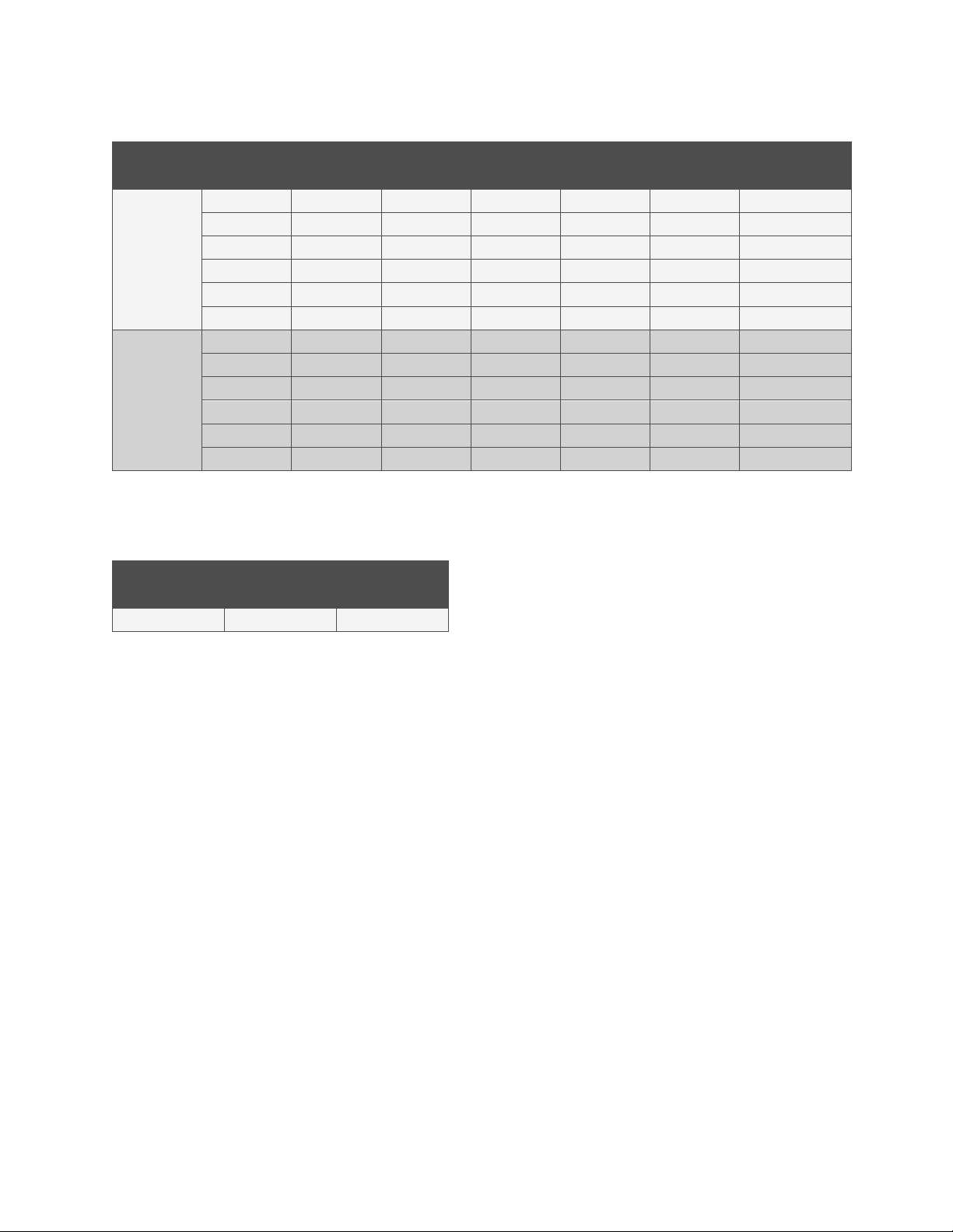
Table 1-1: GMT Fuses
Ampere Rating Part Number Fuse Color
1/4 248610200 Violet
1/2 248610300 Red
3/4 248610500 Brown
1-1/3 248610700 White
2 248610800 Orange
3 248610900 Blue
5 248611000 Green
7-1/2 248611300 Black-White
10 248611200 Red-White
Page 10

Vertiv™ NetSure™ IPE Series Rectifier Installation and User Manual
2
1.1.4 What is in the box
Refer to Table 1-2.
Table 1-2:
Item
(1) 21503878 Mounting Bracket Kit X X X
(2) 632404V1 Mounting Bracket (Big) X X X
(1) 632404V2 Mounting Bracket (Small) X X X
(2) 21101742 Sealing Cable Adapter (Single Large) (DC Input, Bulk DC
Output, 30 A Breaker Output, AC Input)
(1) 21101743 Sealing Cable Adapter (Single Small) (AC Input) X X X
(3) 21101744 Sealing Cable Adapter (Three Cables) (Alarm, GMT Output) X X X
(1) 63126350 Door Hardware Tool X X X
(2) 26011153 M8 Bolts w/ Flat Washer and Lock Washer X X X
(4) 26011018 M5 Bolts w/ Flat Washer and Lock Washer X X X
(2) 26011356 M5 Flat Head Screws X X X
(2) 63126330 Pole Mount Band X X X
(1) 14190607 AC Input Connector (Customer Side) X X X
(2) 14190609 DC Output Connector for GMT Fuse Option (Customer
Side)
(1) 14190611 Alarm Connector (Customer Side) X X X
(1) 14190615 DC Input Connector (Customer Side) X X X
(1) 14190623 DC Output Connector for Bulk Output or Internal Circuit
Breaker Option (Customer Side)
(6) 21101745 Sealing Pin for Unused Holes in Sealing Cable Adapters X X X
(1) UM1R481000CNA Installation and User Manual X X X
P/N 561664
(R48-1000C-4)
X X X
-- -- X
X X --
P/N 561665
(R48-1000C-5)
P/N 561666
(R48-1000C-6)
Page 11

Vertiv™ NetSure™ IPE Series Rectifier Installation and User Manual
3
1.1.5 Replacement components
The input/output terminations are connectorized. For a replacement mating connector, order from Table 1-3. Refer also to Table 1-3
for other replacement components.
Table 1-3: Replacement Components
Part Number Description
14190607 AC Input Connector (Customer Side)
14190609 DC Output Connector for GMT Fuse Option (Customer Side)
14190611 Alarm Connector (Customer Side)
14190615 DC Input Connector (Customer Side)
14190623 DC Output Connector for Bulk Output or Internal Circuit Breaker Option (Customer Side)
63126330 Pole Mount Band
21101742 Sealing Cable Adapter (Single Large) (DC Input, Bulk DC Output, 30 A Breaker Output, AC Input)
21101743 Sealing Cable Adapter (Single Small) (AC Input)
21101744 Sealing Cable Adapter (Three Cables) (Alarm, GMT Output)
21101745 Sealing Pin for Unused Holes in Sealing Cable Adapters
21101755 Door Gasket
Page 12
Vertiv™ NetSure™ IPE Series Rectifier Installation and User Manual
4
Output Voltage (V)
Output Current (A)
1.2 Rectifier Overview
The rectifier provides load power during normal operating conditions. The rectifier is a constant power design. The rectifier is rated
at its maximum output power. This means that, within the normal operating ambient temperature range and input voltage range, the
maximum available output power is a constant 1000 W. Within these ranges, the rectifier operates in one of three modes, depending
upon load demands. Transition between modes is completely automatic. If ambient temperature rises above or input voltage falls
below acceptable values, the rectifier continues to operate but at derated output power levels.
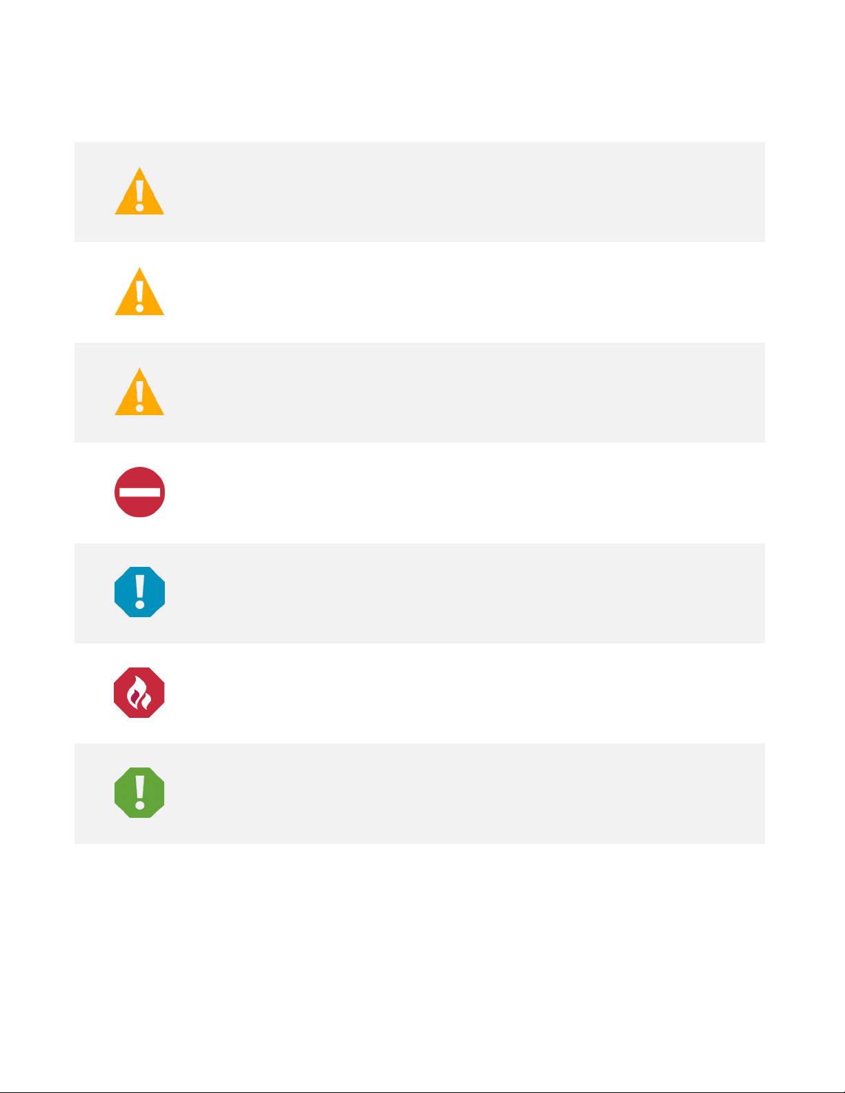
• Constant Voltage Mode: For any initial output voltage setting from -42 VDC to -58 VDC (factory set at -54 VDC), output
voltage remains constant regardless of load. This is the normal operating condition, in which loads are being supplied. The
rectifier operates in the Constant Voltage Mode unless load increases to the point where the product of load current and
output voltage is approximately 1000 W.
• Constant Power Mode: As load increases above approximately 1000 W (non-adjustable), output current continues to
increase, but output voltage decreases as required to maintain constant output power. The rectifier operates in the Constant
Power Mode unless load continues to increase to the point where the current limit setting is reached.
• Constant Current Mode: If load increases to the current limit setting, output voltage decreases linearly to maintain output
current at the current limit setting.
1.3 Rectifier Specifications
The specifications are for a single unit only, unless otherwise noted.
1.3.1 DC output ratings
1. Voltage: -42 VDC to -58 VDC, positive ground. Output voltage is factory set at -54 VDC.
2. Output Power and Current:
a) 1000 W (20.83 A) @ 200 VAC to 250 VAC input and -48 VDC output.
b) 700 W (14.58 A) @ 120 VAC input and -48 VDC output.
3. Output Characteristics: Refer to Figure 1-1 for a graph of output voltage vs. output current.
Figure 1-1: Output Voltage vs. Output Current
Output Voltage vs. Output Current
at Maximum Power 1000 W
60
50
40
30
20
10
0
0 2 4 6 8 10 12 14 16 18 20 22 24
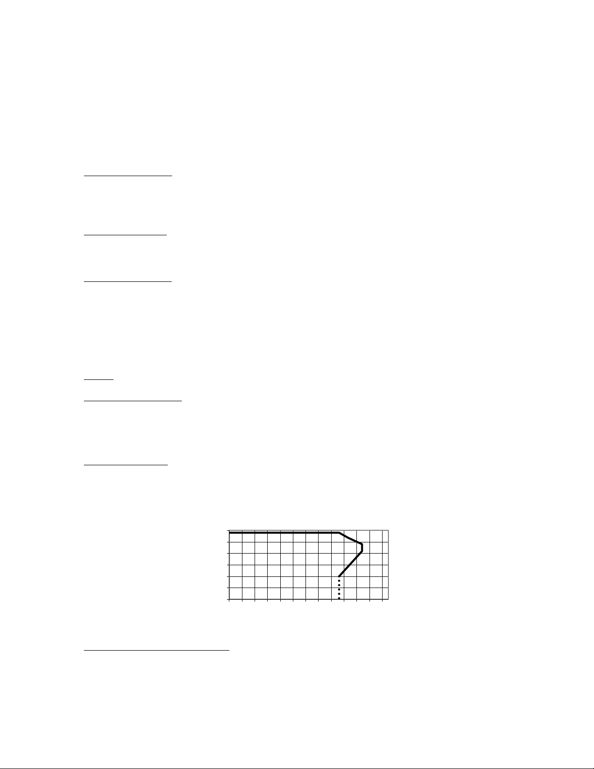
4. Power Derating Based on Input Voltage: The rectifier power varies with changes in input voltage. It uses an advanced power
limitation method. The lower input threshold is 85 VAC. The rectifier can provide its maximum rated power (1000 W) as long
as the input voltage is within the range of 176 VAC to 300 VAC. Below 176 VAC, and down to 85 VAC, the rectifier will
continue to operate normally but will be in a power derating mode. The relationship between the output power and input
voltage is illustrated in Figure 1-2.
Page 13
Vertiv™ NetSure™ IPE Series Rectifier Installation and User Manual
5
% of Output Power
Input Voltage (Vac)
% of Output Power
Temperature (℃)
Figure 1-2: Power Derating Based on Input Voltage
Output Power vs. Input Voltage
and Vo >48 V at Temp ≤55℃
120.0%
100.0%
80.0%
60.0%
40.0%
20.0%
0.0%
0 50 100 150 200 250 300 350
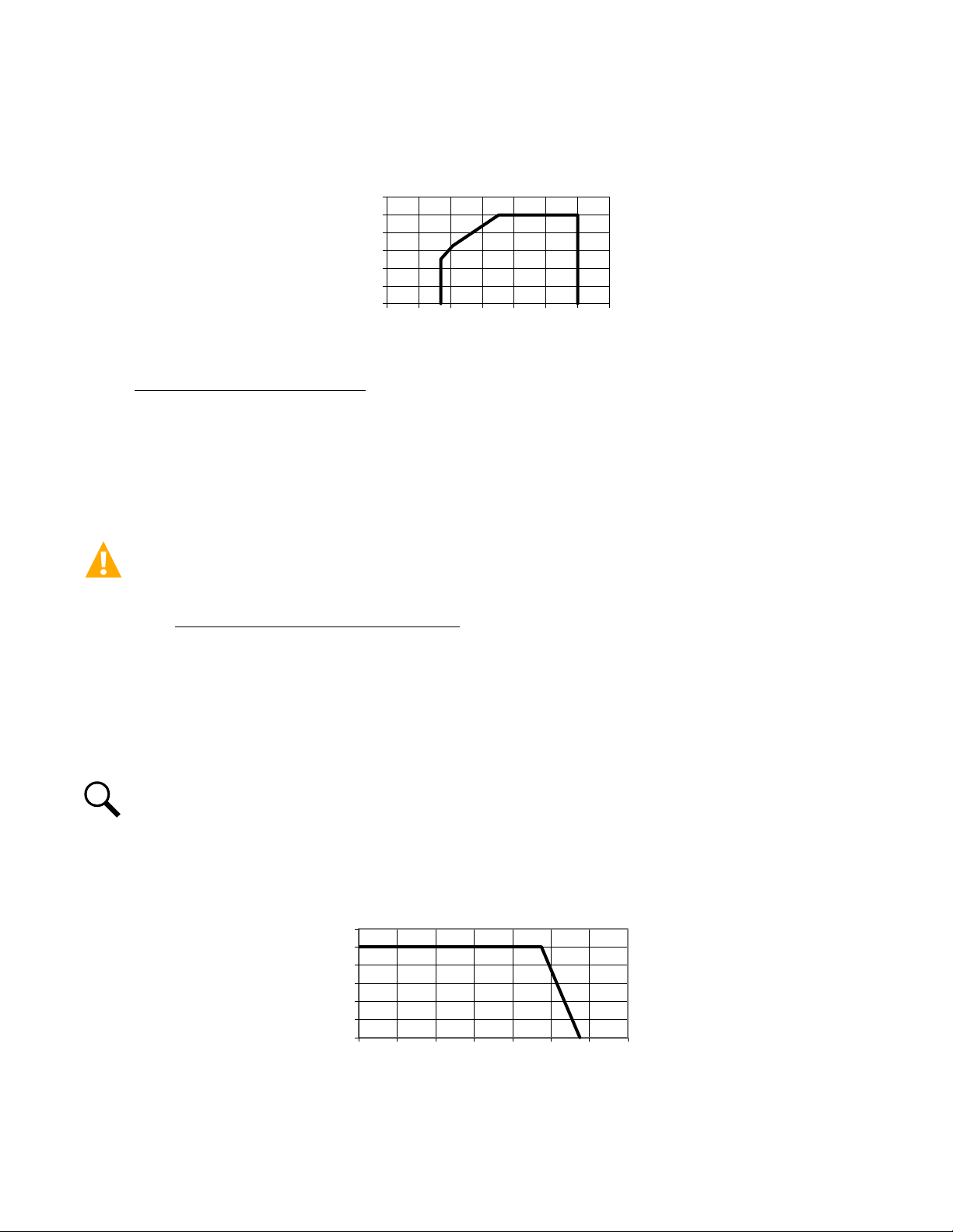
5. Power Derating Based on Temperature: The rectifier delivers full power when operating at an ambient temperature of +55 °C
(+131 °F) or below. The rectifier continuously monitors the ambient temperature surrounding the power conversion circuit. If
this temperature for any reason (such as a high ambient temperature) increases above approximately +55 °C (+131 °F), the
rectifier will not shut down. Rather, the rectifier limits its maximum output power to maintain the temperature of the power
conversion circuit within design parameters. Operation between +55 °C (+131 °C) and +75 °C (+167 °F) will result in output
power being decreased. Full power capability is restored when the temperature decreases to below approximately +55 °C
(+131 °F). Refer to Figure 1-3 to view the relationship between the output power and the ambient temperature.
WARNING! The module is rated for continuous operation at full output power up to +55 °C (+131 °F). Operation between
+55 °C (+131 °F) and +75 °C (+167 °F) will result in output power decrease. Operation above +75 °C (+167 °F) is considered
abnormal and should be used on a temporary
1
Temporary Operation at Abnormal Temperature: Temporary operation is defined as a period of not more than eight
1
basis only.
consecutive hours per day, and a total of not more than 15 days in a year. (This refers to a total of 120 hours in any
given year, but no more than 15 occurrences in that one-year period.)
Other power rating values are as follows (refer to Figure 1-3):
a) At an ambient temperature of +65 °C (+149 °F), the power delivered by the rectifier is 500 W.
b) At an ambient temperature of +75 °C (+167 °F), the power delivered by the rectifier is 0 W.
NOTE!
If used outdoors under full solar radiation, in an ambient of 46 °C the product is rated for 561 W per Telcordia GR-
487-CORE.
Figure 1-3: Power Derating Based on Temperature
Output Power vs. Temperature
at 290 Vac ≥ Vin ≥ 176 Vac
120
100
80
60
40
20
0
-40 -20 0 20 40 60 80 100
Page 14

Vertiv™ NetSure™ IPE Series Rectifier Installation and User Manual
6
6. Regulation:
a) Static: Steady state regulation is ±0.6% as controlled within the rectifier for any and all combinations of load from no
load to full load, input voltage, and input frequency at a constant ambient temperature.
b) Dynamic: Response time ≤200 us and overshoot ≤5% for load changes at 50% - 25% - 50%
and 50% - 75% - 50% at rated output current.
For any step load change within the range of 10% to 90% of full load within 50 us, per Telcordia GR-947-CORE, the
maximum voltage transient will not exceed 5% of the initial steady state voltage within 50±10 us. Recovery to within 1%
of the initial steady state voltage does not exceed 1 milliseconds.
7. Filtering:
a) Voice Band Noise: Peak-peak voltage is ≤200 mV at 0 MHZ to 20 MHZ and normal output voltage.
b) Wide Band Noise: Wideband noise voltage is ≤50 mV at 3.4 kHz to 150 kHz and ≤20 mV at 0.15 MHz to 30 MHz.
c) Discrete Noise Voltage: Discrete noise voltage is ≤5 mV at 3.4 kHz to 150 kHz, ≤3 mV at 150 kHz to 200 kHz, ≤2 mV at
200 kHz to 500 kHz, and ≤1 mV at 500 kHz to 30000 kHz.
d) Psophometric Noise: Psophometric noise is ≤2 mV typical at 220 VAC input, 53.5 VDC output, and 30% to 90% of rated
load for more than one rectifier.
1.3.2 AC input ratings
1. Voltage: Nominal 120 VAC / 208 VAC / 220 VAC / 230 VAC / 240 VAC, single phase, 3-wire, 50 Hz / 60 Hz, with an operating
range of 85 VAC to 300 VAC. Acceptable input frequency range is 45 Hz to 65 Hz.
Permitted Variation: 85 VAC to 300 VAC.
2. Harmonic Content (THD): Meets EN61000-3-2. ≤5% from 50% to 100% of rated output current at 220 VAC.
3. Inrush Current: Peak does not exceed 1.5 times of the peak value of the maximum steady-state input current at full load, 220
VAC input voltage, and for any duration of AC input interrupts. Under the above conditions, standard AC distribution circuit
breakers will not trip.
4. Typical Input Data: 50 Hz input.
a) Refer to Table 1-4.
b) Maximum Input Current: Refer to Table 1-5.
c) Efficiency Curve: Refer to Figure 1-4.
5. Typical Input Data: 60 Hz input.
a) Refer to Table 1-6.
b) Maximum Input Current: Refer to Table 1-7.
c) Efficiency Curve: Refer to Figure 1-5 and Figure 1-6.
Page 15
7
Table 1-4: Typical Input Data with 50 Hz Input
Vertiv™ NetSure™ IPE Series Rectifier Installation and User Manual
Nominal
Input Voltage
208
240
Note:
System output is initially adjusted to 54 volts DC as measured at the system sense point at 50% of full load
Percent
of Full Load
0 0.286 55.84 4.73 0.10023 -- 16.137
25 1.26 258.754 245.374 0.9 48 57 90.79 77.1101
50 2.34 485.81 479.1 4 0.98624 94.33 92.6646
75 3.489 725.77 721.56 0.99407 94.81 127.7476
100 4.66 970. 24 967.15 0.99682 94.76 172.9354
110 5.01 1041.68 1038.95 0.99725 94.70 187.9968
0 0.33 73.4 4.908 0.06636 -- 16.745
25 1.12 265.36 244.52 0.92218 91.16 73.7573
50 2.02 482.99 477.956 0.9897 7 94.59 88.2566
75 3.015 724.2 719.46 0.99357 95.10 120.301
100 4.033 969.3 966.68 0.99727 95.09 161.8856
110 4.32 1037.32 103 5.1 0.99778 95.05 174.7991
Input Current
(Amperes)
and nominal input. “Percent of Full Load” refers to percent of 17.24 amperes.
Table 1-5: Maximum Input Current with 50 Hz Input
Nominal Input
Voltage
Input
Voltage
Input Current
(Amperes)
Input
VA
Input
Watts
Power
Factor
Efficiency
%
Heat Dissipation
BTU/Hr
208/240 176 7.5
Note:
At 100% of full load with output adjusted to 58 volts DC as
measured at the output terminals.
Page 16

Vertiv™ NetSure™ IPE Series Rectifier Installation and User Manual
8
Table 1-6: Typical Input Data with 60 Hz Input
Nominal
Input Voltage
120
208
240
Percent
of Full Load
0 0.233 28.132 4.863 0.17286 -- 16.59
25 2.175 262.037 256.726 0.97973 90.76 80.96
50 4.185 503.75 499.92 0.99241 93.09 117.85
75 6.278 754.97 751.24 0.99505 92.94 181.02
100 -- -- -- -- -- --
110 -- -- -- -- -- --
0 0. 34 67.243 4.713 0.07574 -- 16.08
25 1.284 263.654 245.112 0.92942 90.80 76.95
50 2.35 487.82 478.89 0.98189 94.35 92.36
75 3.49 726.85 721.46 0.99271 94.81 1 27.7 7
100 4.66 970. 53 966.92 0.99636 94.78 172.29
110 5.006 1042 .06 1038.81 0.99693 94.70 187.70
0 0.381 87.67 4.728 0.05362 -- 16.13
25 1.155 272.863 244.46 0.89528 91.15 73.79
50 2.027 4 84.678 478.99 0.98601 94.37 91.97
75 3.02 725.35 719.45 0.9919 95.10 120.31
100 4.023 966.79 963.65 0.99679 95.12 160.58
110 4.31 1037.7 2 1035.15 0.99752 95.05 174.97
Input Current
(Amperes)
Input
VA
Input
Watts
Power
Factor
Efficiency
%
Heat Dissipation
BTU/Hr
Note:
System output is initially adjusted to 54 volts DC as measured at the system sense point at 50% of full load
and nominal input. “Percent of Full Load” refers to percent of 17.24 amperes.
Table 1-7: Maximum Input Current with 60 Hz Input
Nominal Input
Voltage
208/240 176 7.5
Note:
At 100% of full load with output adjusted to 58 volts DC as
Input
Voltage
Input Current
(Amperes)
measured at the output terminals.
Page 17

9
Figure 1-4: Efficiency Curve (@ 230 VAC, 50 Hz)
Efficiency (%)
98
96
94
92
90
88
86
84
0 10 20 30 40 50 60 70 80 90 100
Figure 1-5: Efficiency Curve (@ 240 VAC, 60 Hz)
98
Vertiv™ NetSure™ IPE Series Rectifier Installation and User Manual
Efficiency Curve
Load (% of rated load)
Efficiency Curve
96
94
92
90
88
Efficiency (%)
86
84
0 10 20 30 40 50 60 70 80 90 100 110 120
Figure 1-6: Efficiency Curve (@ 120 VAC, 60 Hz)
98
96
94
92
90
Load (% of rated load)
Efficiency Curve
88
Efficiency (%)
86
84
0 10 20 30 40 50 60 70 80 90 100 110 120
Load (% of rated load)
Page 18

Vertiv™ NetSure™ IPE Series Rectifier Installation and User Manual
10
1.3.3 Environmental ratings
1. Operating Ambient Temperature Range:
a) -40 °C (-40 °F) to +55 °C (+131 °F) with full power performance.
b) +55 °C (+131 °F) to +75 °C (+167 °F) with derating output.
c) Temperature Coefficient: 0.02% per degrees Celsius.
2. Storage Ambient Temperature Range: -40 °C (-40 °F) to +70 °C (+158 °F).
3. Relative Humidity: This rectifier is capable of operating in an ambient relative humidity range of 0% to 95%.
4. Altitude: -200 feet (- 61 m) to 13000 feet (3900 m).
5. Surge Protection: EN61000-4-5 up to level 4, Telcordia GR-1089-Core, IEEE C62.41-2002, YD/T 731-2002.
Performance Criteria B.
AC Power Terminals
Test Level
Line to Line Line to Ground
± 4 kV ± 4 kV 2 ohms B
NA ± 6 kV 12 ohms B
Source
Impedance
Performance
Criteria
DC Power Terminals:
Test Level
Line to Line Line to Ground
± 500 V ± 500 V 2 ohms B
± 800 V ± 800 V 2 ohms B
Source
Impedance
Performance
Criteria
The test method is described in EN 61000-4-5. In this test the DC-cables shall
be 5 m long.
6. High Voltage Category (per UL60950): III
7. Power Distribution System: TN/TT/IT
8. EMI/RFI Suppression:
a) The rectifier conforms to the requirements of FCC rules Part 15, Class B for radiated and conducted emissions limits.
b) The rectifier conforms to the requirements of European Norm, EN55022, Class B for radiated and conducted emissions
limits.
1.3.4 Compliance information
1. EMC: ETSI EN 300 386, FCC CFR 47 Part 15 class B, Telcordia GR-1089-CORE.
2. EMI Load Range: 10% to 100%.
3. Safety: IEC 60950, EN 60950.
Page 19

11
4. Product is GR-3108 Class 4 compliant.
1.3.5 Standard features
1. Type of Power Conversion Circuit: High frequency.
2. Input Protection:
a) Input Over/Under Voltage Protection: The rectifier will shut down at low or high voltage input; based on the following
voltage levels:
Low Voltage Disable Point: 80 VAC, ±5 V; hysteresis is at least 15 VAC for restart.
High Voltage Disable Point: 305 VAC, ±5 V; hysteresis is at least 10 VAC for restart.
Vertiv™ NetSure™ IPE Series Rectifier Installation and User Manual
b) Between 85 VAC and 176 VAC the output power will be
derated linearly based on the input voltage as
follows:
At input voltage of 85 VAC with output >48 VDC, maximum output power is 500 W.
At input voltage of 176 VAC with output >48 VDC, maximum output power is 1000 W.
3. Output Protection:
a) Overload / Reverse Current: The rectifier has a 28 A fuse wire in the negative output DC bus. This fuse is not customer
replaceable.
b) Current Limiting: The rectifier has a current limit function. The current limit point is factory set at 20.83 A. The current
limit accuracy is ±1.5 A when the output voltage ranges from 42 VDC to 48 VDC.
c) Advanced Current Limit Function: The rectifier has an advanced Current Limit Function. When a short circuit occurs
at the rectifier output terminals, the rectifier will keep its output current at a constant value (factory set at 17 A ± 6 A).
This function effectively protects the rectifier and the equipment connected to the rectifier. When the short circuit fault
is cleared, the rectifier will automatically restore back to normal operation.
d) High Voltage Shutdown:
• Fixed Control: If rectifier output voltage exceeds a factory set value of 59.5 VDC and the rectifier is delivering more
than 10% of its rated current, the rectifier shuts down. (The restart hysteresis is 0.5 V ±0.2 V.)
The rectifier then restarts and a HVSD restart timer starts (factory set at 5 minutes). If output voltage again
exceeds the high voltage shutdown value before the HVSD restart timer expires, the rectifier shuts down and locks
out. Manual restart is then required (by turning power to the rectifier off , waiting until the LEDs on the rectifier
extinguish, then turning power to the rectifier on). If the rectifier does not experience a high voltage condition
before the HVSD restart timer expires, the restart circuit is reset.
If two or more rectifiers are paralleled, only the rectifier causing the high voltage condition shuts down.
• Backup: If rectifier output voltage exceeds 59.5 VDC ±0.5 V (non-adjustable), the rectifier shuts down. The
rectifier then restarts and a HVSD restart timer starts (factory set at 5 minutes). If output voltage again exceeds
the high voltage shutdown value before the HVSD restart timer expires, the rectifier shuts down and locks out.
Manual restart is then required (by turning power to the rectifier off, waiting until the LEDs on the rectifier
extinguish, then turning power to the rectifier on).
4. Over-Temperature Protection: The rectifier provides over temperature protection by derating output power and recovers
automatically.
Page 20

Vertiv™ NetSure™ IPE Series Rectifier Installation and User Manual
12
5. Active Load Sharing: The rectifier uses advanced digital active load sharing technology that maintains balancing to within 5%
of rated current.
6. Paralleling: Up to three (3) rectifiers can be connected in parallel in one system. Do not exceed the load rating of a single
rectifier. See “Paralleling Rectifiers” on page 32.
7. Rectifier Output Current Imbalance:
a) When the average current of all rectifier modules is greater than 20% of full rated current, and the difference between
local rectifier current and average current is greater than 16% of full rated current, the yellow protection indicator will
illuminate.
b) When the average current of all rectifier modules is greater than 10% of full rated current, and local rectifier current is
less than 2% of full rated current, then the red fault indicator will illuminate.
8. Monitoring Function: The rectifier has a built-in advanced DSP that monitors and controls the operation of the rectifier.
1.3.6 Mechanical specifications
1. Dimensions and Weight:
Refer to
2. Indicators (located behind door):
a) Power (Green LED)
b) Protection (Yellow LED)
c) Alarm (Red LED)
Figure 1-7.
Page 21

13
Figure 1-7: Overall Dimensions
Notes:
1. Dimensions are in inches,
unless otherwise specified.
2. Finish: Aluminum with
Powder Painted.
3. Weight:
Bottom View
Vertiv™ NetSure™ IPE Series Rectifier Installation and User Manual
Net: 5 kg (11 lbs.)
Shipping:
Rear View
7.68
Top View
3.66
14.17
4.61
17.05
Front View
Right Side ViewLeft Side View
Page 22

Vertiv™ NetSure™ IPE Series Rectifier Installation and User Manual
14
2 Installation
2.1 General Requirements
CAUTION! PREVENT EQUIPMENT DAMAGE, FROM CONDENSATION
Until the product is turned up for service, the top cover of the product should remain closed as delivered from the factory. If
the top cover of the product is opened when in storage, it shall be placed in its sealed protective packaging with the provided
desiccant bags to prevent condensation. Once the product is in service, the heat generated by the product is sufficient to
prevent humidity build up.
• This product is intended for installation in network telecommunications facilities (CO, vault, hut or other electronic equipment
enclosure) or as an outside plant cabinet.
• This product is intended to be connected to the common bonding network in a network telecommunications facility (CO,
vault hut or other equipment enclosure).
• The DC return connection to this system can remain isolated from system frame and chassis (DC-I). The DC return is not
connected to the power supply chassis from the factory.
• This product is suitable for installation as part of the Common Bonding Network (CBN).
2.2 Tools and Test Equipment Required for Installation
The following tools, test equipment and materials are required for the physical installation of the product:
• Non-Contact Voltage Detector
• Digital Multimeter (DMM), 0 VDC to 200 VDC, 0 VAC to 300 VAC
• Torque Wrench
• Ratchet, 1/2”, 3/8” and 1/4” Drives
• Socket Set Range from M4 to M13
• 3” and 6” Extensions, 1/4” and1/2” Drive
• Carpenters Level
• Lineman’s Scissors
• Lineman’s Strippers
• Lineman’s Cutters
• Crimping Tool with Dies for 6 AWG to 14 AWG
• Electrician’s Insulated Screwdrivers, Phillips, No. 1 and 2
• Electrician’s Insulated Screwdrivers, Flat Blade, Small and Large
• NO-OX-ID or Approved Equivalent
Page 23

Vertiv™ NetSure™ IPE Series Rectifier Installation and User Manual
15
Front View Front
1
3
2.3 Installing the Rectifier
2.3.1 General
The rectifier can be pole mounted or secured to a suitable wall.
For mounting; use a corrosion inhibiting compound (CIC) that is conductive inside the tapped mounting holes to keep water away, or
use organically plated stainless steel bolts. See Figure 2-3 and Figure 2-7.
2.3.2 Front door
If the front door is opened during installation, perform the following procedure to properly close and secure the door.
Procedure
1. Close the door.
2. Hand tighten each screw, ensuring the screw and washer beneath it are centered in the mounting hole.
3. Torqued each screw in the following order (Figure 2-1) to 29 Kgf cm (2.9 Nm) (25 in-lbs).
Figure 2-1: Torque Sequence
2
4
1
23
4
2.3.3 Pole installation procedure
NOTE!
1. Unpack the rectifier and mounting accessories.
2. Install the mounting bracket (big) in the appropriate top position on the pole with the supplied pole mount band. Tighten the
Torque all hardware to the values shown in the illustrations.
pole mount band to the pole (torque to 45 in-lbs). The pole mount band accommodates poles from 6” to 12” in diameter.
Refer to Figure 2-2.
3. Install mounting brackets to the rear panel of the rectifier with the supplied hardware. Refer to Figure 2-3.
4. Secure the top of the rectifier to the pole by securing the mounting bracket (small) to the mounting bracket (big) with the
supplied M8 bolts. Refer to Figure 2-4.
Page 24

Vertiv™ NetSure™ IPE Series Rectifier Installation and User Manual
16
Pole
Mounting Bracket (Big)
P/N: 632404V1
Pole Mount Band
P/N: 63126330
Torque to 5.08 Nm (45 in-lbs).
M5 Flat Head Screws (2)
P/N: 26011356
Torque to
2.02 to 2.69 Nm
(18 to 24 in-lbs).
M5 Bolts (2)
P/N: 26011018
Torque to
2.02 to 2.69 Nm
(18 to 24 in-lbs).
For mounting; use a corrosion inhibiting
compound (CIC) that is conductive inside
the tapped mounting holes to keep water
away, or use organically plated stainless
steel bolts.
Mounting Bracket (Small)
P/N: 632404V2
Mounting Bracket (Big)
P/N: 632404V1
5. Secure the bottom of the rectifier to the pole by securing the mounting bracket (big) to the pole with the supplied pole
mount band. Torque to 45 in-lbs . Refer to Figure 2-5.
Figure 2-2: Installing the Mounting Bracket to the Pole with the Pole Mount Band
Figure 2-3: Installing the Mounting Brackets to the Rectifier
Page 25

17
Figure 2-4: Securing the Rectifier to the Pole at the Top
M8 Bolts
(2 places)
P/N: 26011153
Torque to
13 to 16 Nm
(115 to 141 in-lbs).
Door hardware (4X)
torque is 29 Kgf cm
(2.9 Nm) (25 in-lbs).
Pole Mount Band
P/N: 63126330
Torque to 5.08 Nm (45 in-lbs).
Mounting Bracket (Big)
P/N: 632404V1
Vertiv™ NetSure™ IPE Series Rectifier Installation and User Manual
Figure 2-5: Securing the Rectifier to the Pole at the Bottom
Page 26

Vertiv™ NetSure™ IPE Series Rectifier Installation and User Manual
18
5
(0.2)
Mounting Bracket (Big)
P/N: 632404V1
Mounting Bracket (Big)
P/N: 632404V1
M5 Bolts (4)
P/N: 26011018
Torque to
2.02 to 2.69 Nm
(18 to 24 in-lbs).
For mounting; use a corrosion inhibiting
compound (CIC) that is conductive inside
the tapped mounting holes to keep water
away, or use organically plated stainless
steel bolts.
2.3.4 Wall installation procedure
1. Drill appropriately sized holes for the customer provided M5 wall anchors being used into the wall as shown in Figure 2-6.
Note that the rectifier can be mounted horizontal or vertical. Figure 2-6 shows horizontal mounting. Install the M5 wall
anchors into the holes.
2. Install mounting brackets to the rear panel of the rectifier. Refer to Figure 2-7.
3. Secure the rectifier to the wall using the wall anchors previously installed. Refer to Figure 2-8.
Figure 2-6: Wall Mounting Hole Positions
80
Dia.
(3)
mm
(inch)
405
(16)
Figure 2-7: Installing the Mounting Brackets to the Rectifier
Page 27

19
Figure 2-8: Securing the Rectifier to the Wall
Wall
Vertiv™ NetSure™ IPE Series Rectifier Installation and User Manual
Page 28

Vertiv™ NetSure™ IPE Series Rectifier Installation and User Manual
20
GMT Fuses
2.4 Installing GMT Fuses (P/N 561666 [R48-1000C-6] Only)
If the rectifier is equipped with an optional internal 6-position GMT fuse block, install appropriately sized GMT fuses into this fuse
block.
Procedure
1. Loosen the screws on the rectifier front door (four) and open the front door, as show in Figure 2-9.
2. Install the GMT fuses. Record fuse information on the label next to the fuse block.
3. Close the rectifier front door by following the procedure in “Front door” on page 15.
Figure 2-9: Installing GMT Fuses (P/N 561666 [R48-1000C-6] Only)
3 Making Electrical Connections
3.1 Important Safety Instructions
DANGER! Adhere to the “Important Safety Instructions” presented at the front of this document.
3.2 Wiring Considerations
All wiring and branch circuit protection should follow the current edition of the American National Standards Institute (ANSI)
approved National Fire Protection Association's (NFPA) National Electrical Code (NEC), and applicable local codes. For operation in
countries where the NEC is not recognized, follow applicable codes.
3.3 Frame Ground Connection
For grounding requirements, refer to the current edition of the American National Standards Institute (ANSI) approved National Fire
Protection Association’s (NFPA) National Electrical Code (NEC), applicable local codes, and your specific site requirements.
Captive fasteners (for M8 bolts) for frame ground lugs are located on each mounting bracket. Holes are spaced on 1-inch centers.
Refer to Figure 3-1 for location.
Page 29

21
Figure 3-1: Frame Grounding Location
Captive Fasteners
for Frame Ground Lugs
(M8 on 1-inch centers)
Rear
Captive Fasteners
for Frame Ground Lugs
(M8 on 1-inch centers)
Vertiv™ NetSure™ IPE Series Rectifier Installation and User Manual
3.4 Customer Wiring to the Mating Connectors
Procedure
NOTE!
NOTE!
inside the connector housing as the sleeve is tightened to the connector housing. Perform these steps in the correct order to
prevent this from happening.
1. Strip 7.5 ± 0.5 mm (0.3 ± 0.02 inch) of insulation off the wires.
2. With the dust cap installed, unscrew the sleeve from the connector housing to expose the wiring terminals.
3. Remove the rear pressing nut.
4. Separate the sleeve from the sealing cable adapter housing.
5. Slide the cable(s) through the rear pressing nut, then through the appropriate opening(s) in the sealing cable adapter
NOTE!
6. Slide the appropriate wires into the appropriate pins of the connector housing. Tighten the screw in the connector housing
Refer to
Figure 3-2
through
Figure 3-6
as this procedure is performed.
If the sleeve and sealing cable adapter housing are not separated before installing the cable, the cable may twist
installed in the sealing cable adapter housing, and finally through the sleeve.
If multiple sealing cable adapters are furnished, select and install the appropriate sealing cable adapter.
to secure the wire. Torque to 0.8 Nm (7 in-lbs).
7. Tighten the sleeve to the connector housing.
8. Slide the sealing cable adapter housing into the sleeve.
9. Tighten the rear pressing nut to the sleeve. Torque to 6.5 Nm (58 in-lbs).
Page 30

Vertiv™ NetSure™ IPE Series Rectifier Installation and User Manual
22
Sealing
Cable
Adapter
P/N 14190611 (Alarm Cable)
Dust
Cap
Connector
Housing
Sleeve
Rear
Pressing
Nut
Sealing
Cable
Adapter
Housing
NOTE! If the sleeve and sealing cable adapter housing
are not separated before installing the cable, the cable
may twist inside the connector housing as the sleeve is
tightened to the connector housing. Perform these steps
in the correct order to prevent this from happening.
1. Strip 7.5 ± 0.5 mm (0.3 ± 0.02 inch)
of insulation off the wires.
2. With the dust cap installed, unscrew the sleeve from
the connector housing to expose the wiring terminals.
3. Remove the rear pressing nut.
4. Separate the sleeve from the sealing cable adapter
housing.
5. Slide the cable(s) through the rear pressing nut,
then through the appropriate opening(s) in the
sealing cable adapter installed in the sealing cable
adapter housing, and finally through the sleeve.
NOTE: If multiple sealing cable adapters are
furnished, select and install the appropriate sealing
cable adapter.
6. Slide the appropriate wires into the appropriate pins
of the connector housing. Tighten the screw in the
connector housing to secure the wire.
Torque to 0.8 N m (7 in-lbs).
7. Tighten the sleeve to the connector housing.
8. Slide the sealing cable adapter housing into the
sleeve.
9. Tighten the rear pressing nut to the sleeve.
Torque to 6.5 N m (58 in-lbs).
Sealing cable adapter provided.
Maximum cable diameter is 6.1 mm to 8.1
mm (0.24” to 0.32”).
Insert provided plug into any empty cable
hole. If this connector is not used, place
dust cap onto connector.
The following are some cable choices that
fit this connector:
Alarm Contact Cabling:
Belden Waterdog 5504G1 (6/C) 22AWG,
300V
CAN Bus Cabling:
Belden Waterdog 5502G1 (4/C) 22AWG,
300V
Note: Cable choices should be based on
the environment that the power system is
located as well as any National Electrical
Code and local regulations. Choices
above are just examples of cables that will
fit.
3
4 5
1 8
2
6
7
Rectifier Fail to terminals 1 and 2.
AC Fail to terminals 3 and 4.
Fuse or Circuir Breaker Alarm to
terminals 7 and 8 (if available).
CAN_H to terminal 5.
CAN_L to terminal 6.
ALARM
Pins for wire connections.
Accepts 22 AWG wires maximum.
Figure 3-2: Customer Wiring to the Mating Connector P/N 14190611 (Alarm Connector)
(Mates to Connector Labeled Y in Figure 3-7 to Figure 3-9)
Page 31

Vertiv™ NetSure™ IPE Series Rectifier Installation and User Manual
23
P/N 14190607 (AC Input)
Dust
Cap
Connector
Housing
Sleeve
Rear
Pressing
Nut
NOTE! If the sleeve and sealing cable adapter housing
are not separated before installing the cable, the cable
may twist inside the connector housing as the sleeve is
tightened to the connector housing. Perform these steps
in the correct order to prevent this from happening.
1. Strip 7.5 ± 0.5 mm (0.3 ± 0.02 inch)
of insulation off the wires.
2. With the dust cap installed, unscrew the sleeve from
the connector housing to expose the wiring terminals.
3. Remove the rear pressing nut.
4. Separate the sleeve from the sealing cable adapter
housing.
5. Slide the cable(s) through the rear pressing nut,
then through the appropriate opening(s) in the
sealing cable adapter installed in the sealing cable
adapter housing, and finally through the sleeve.
NOTE: If multiple sealing cable adapters are
furnished, select and install the appropriate sealing
cable adapter.
6. Slide the appropriate wires into the appropriate pins
of the connector housing. Tighten the screw in the
connector housing to secure the wire.
Torque to 0.8 N m (7 in-lbs).
7. Tighten the sleeve to the connector housing.
8. Slide the sealing cable adapter housing into the
sleeve.
9. Tighten the rear pressing nut to the sleeve.
Torque to 6.5 N m (58 in-lbs).
Sealing
Cable
Adapter
Housing
Two sealing cable adapters provided.
Maximum cable diameter is 8.92 mm to 9.45 mm
(0.35” to 0.37”) for small cable adapter.
Maximum cable diameter is 12.5 mm to 16 mm
(0.49” to 0.63”) large cable adapter.
The following are some cable choices that fit this
connector:
Southwire Royal SJ00W, 14/3, 300V
General Cable HF360 Carolprene SJ00W, 14/3,
300V
Note: Cable choices should be based on the
environment that the power system is located as
well as any National Electrical Code and local
regulations. Choices above are just examples of
cables that will fit.
Sealing
Cable
Adapter
GND
GND
L2/N
L2/N
L1
L1
AC INPUT
Line to terminal L1.
Line/Neutral to terminal L2/N.
Ground to terminal GND.
Pins for wire connections.
Accepts wires in the range
of 22 AWG to 11 AWG.
Figure 3-3: Customer Wiring to the Mating Connector P/N 14190607 (AC Input Connector)
(Mates to Connector Labeled X in Figure 3-7 to Figure 3-9)
Page 32

Vertiv™ NetSure™ IPE Series Rectifier Installation and User Manual
24
P/N 14190623 (-48 VDC Output)
Dust
Cap
Connector
Housing
Sleeve
Sealing
Cable
Adapter
Sealing
Cable
Adapter
Housing
Rear
Pressing
Nut
NOTE! If the sleeve and sealing cable adapter housing
are not separated before installing the cable, the cable
may twist inside the connector housing as the sleeve is
tightened to the connector housing. Perform these steps
in the correct order to prevent this from happening.
1. Strip 7.5 ± 0.5 mm (0.3 ± 0.02 inch)
of insulation off the wires.
2. With the dust cap installed, unscrew the sleeve from
the connector housing to expose the wiring terminals.
3. Remove the rear pressing nut.
4. Separate the sleeve from the sealing cable adapter
housing.
5. Slide the cable(s) through the rear pressing nut,
then through the appropriate opening(s) in the
sealing cable adapter installed in the sealing cable
adapter housing, and finally through the sleeve.
NOTE: If multiple sealing cable adapters are
furnished, select and install the appropriate sealing
cable adapter.
6. Slide the appropriate wires into the appropriate pins
of the connector housing. Tighten the screw in the
connector housing to secure the wire.
Torque to 0.8 N m (7 in-lbs).
7. Tighten the sleeve to the connector housing.
8. Slide the sealing cable adapter housing into the
sleeve.
9. Tighten the rear pressing nut to the sleeve.
Torque to 6.5 N m (58 in-lbs).
Sealing cable adapter provided.
Maximum cable diameter is 12.5 mm to
16 mm (0.49” to 0.63”).
The following are some cable choices
that fit this connector:
WR-VG102ST-BRDA, 10/2, 600V from
Rosenberger
HF382 Carolprene SJ00W, 10/2, 300V
from General Cable
Note: Cable choices should be based on
the environment that the power system is
located as well as any National Electrical
Code and local regulations. Choices
above are just examples of cables that
will fit.
Pins for wire connections.
Accepts wires in the range
of 22 AWG to 10 AWG.
3+
4+ 4-
1+ 1-
2+
3-
2-
-48 VDC OUTPUT
Return to terminal 3+
-48 VDC to terminal 3-.
Figure 3-4: Customer Wiring to the Mating Connector P/N 14190623 (-48 VDC Output Connector)
(Mates to Connector Labeled Z in Figure 3-7 and Figure 3-8) (this connector is not used with Spec. No. 561666)
Page 33

Vertiv™ NetSure™ IPE Series Rectifier Installation and User Manual
25
Sealing cable adapter provided.
Maximum cable diameter is 6.1 mm to 8.1 mm
(0.24” to 0.32”)”.
Insert provided plug into any empty cable hole.
The following are some cable choices that fit this
connector:
General Cable HF312 Carolprene SJ00W, 16/2,
300V
Belden Waterdog 5240U1 (2/C) 16AWG, 300V
Note: Cable choices should be based on the environment that the power system is located as well as
any National Electrical Code and local regulations.
Choices above are just examples of cables that will
fit.
Dust
Cap
Connector
Housing
Sleeve
Sealing
Cable
Adapter
Rear
Pressing
Nut
P/N 14190609
(-48 VDC GMT Fuse Output)
3+
4+ 4-
1+ 1-
2+
3-
2-
3+
4+ 4-
1+ 1-
2+
3-
2-
-48 VDC OUTPUT 1
Load 1: Return to terminal 1+, -48 VDC to terminal 1-.
Load 2: Return to terminal 3+, -48 VDC to terminal 3-.
Load 3: Return to terminal 4+, -48 VDC to terminal 4-.
-48 VDC OUTPUT 2
Load 4: Return to terminal 1+, -48 VDC to terminal 1-.
Load 5: Return to terminal 3+, -48 VDC to terminal 3-.
Load 6: Return to terminal 4+, -48 VDC to terminal 4-.
Pins for wire connections.
Accepts wires in the range
of 22 AWG to 16 AWG.
NOTE! If the sleeve and sealing cable adapter housing
are not separated before installing the cable, the cable
may twist inside the connector housing as the sleeve is
tightened to the connector housing. Perform these steps
in the correct order to prevent this from happening.
1. Strip 7.5 ± 0.5 mm (0.3 ± 0.02 inch)
of insulation off the wires.
2. With the dust cap installed, unscrew the sleeve from
the connector housing to expose the wiring terminals.
3. Remove the rear pressing nut.
4. Separate the sleeve from the sealing cable adapter
housing.
5. Slide the cable(s) through the rear pressing nut,
then through the appropriate opening(s) in the
sealing cable adapter installed in the sealing cable
adapter housing, and finally through the sleeve.
NOTE: If multiple sealing cable adapters are
furnished, select and install the appropriate sealing
cable adapter.
6. Slide the appropriate wires into the appropriate pins
of the connector housing. Tighten the screw in the
connector housing to secure the wire.
Torque to 0.8 N m (7 in-lbs).
7. Tighten the sleeve to the connector housing.
8. Slide the sealing cable adapter housing into the
sleeve.
9. Tighten the rear pressing nut to the sleeve.
Torque to 6.5 N m (58 in-lbs).
Sealing
Cable
Adapter
Housing
Figure 3-5: Customer Wiring to the Mating Connector P/N 14190609 (-48 VDC GMT Output Connector)
(Mates to Connector Labeled Z in Figure 3-9) (this connector is not used with Spec. No. 561664 or Spec. No.
561665)
Page 34

Vertiv™ NetSure™ IPE Series Rectifier Installation and User Manual
26
-48 VDC INPUT
Return to terminal 3+.
-48 VDC to terminal 3-.
3+
4+ 4-
1+ 1-
2+
3-
2-
Pins for wire connections.
Accepts wires in the range
of 22 AWG to 10 AWG.
Sealing cable adapter provided.
Maximum cable diameter is 12.5 mm to
16 mm (0.49” to 0.63”).
The following are some cable choices
that fit this connector:
WR-VG102ST-BRDA, 10/2, 600V from
Rosenberger
HF382 Carolprene SJ00W, 10/2, 300V
from General Cable
Note: Cable choices should be based on
the environment that the power system is
located as well as any National Electrical
Code and local regulations. Choices
above are just examples of cables that
will fit.
P/N 14190615 (-48 VDC Input)
Dust
Cap
Connector
Housing
Sleeve
Sealing
Cable
Adapter
Rear
Pressing
Nut
NOTE! If the sleeve and sealing cable adapter housing
are not separated before installing the cable, the cable
may twist inside the connector housing as the sleeve is
tightened to the connector housing. Perform these steps
in the correct order to prevent this from happening.
1. Strip 7.5 ± 0.5 mm (0.3 ± 0.02 inch)
of insulation off the wires.
2. With the dust cap installed, unscrew the sleeve from
the connector housing to expose the wiring terminals.
3. Remove the rear pressing nut.
4. Separate the sleeve from the sealing cable adapter
housing.
5. Slide the cable(s) through the rear pressing nut,
then through the appropriate opening(s) in the
sealing cable adapter installed in the sealing cable
adapter housing, and finally through the sleeve.
NOTE: If multiple sealing cable adapters are
furnished, select and install the appropriate sealing
cable adapter.
6. Slide the appropriate wires into the appropriate pins
of the connector housing. Tighten the screw in the
connector housing to secure the wire.
Torque to 0.8 N m (7 in-lbs).
7. Tighten the sleeve to the connector housing.
8. Slide the sealing cable adapter housing into the
sleeve.
9. Tighten the rear pressing nut to the sleeve.
Torque to 6.5 N m (58 in-lbs).
Sealing
Cable
Adapter
Housing
Figure 3-6: Customer Wiring to the Mating Connector P/N 14190615 (-48 VDC Input Connector)
(Mates to Connector Labeled W in Figure 3-7 to Figure 3-9)
3.5 Electrical Connections Diagrams
Refer to Figure 3-7 through Figure 3-9.
Page 35

27
Figure 3-7: Electrical Connections Diagram - External, P/N 561664 (R48-1000C-4)
Customer Wiring
DC OUTPUT
Return -48 VDC
LOAD 1
3+
3-
3+
4+ 4-
1+ 1-
2+
3-
2-
DC INPUT
+ -
DC Input
DC INPUT
3+ 3-
3+
4+ 4-
1+ 1-
2+
3-
2-
ALARM
Rect Fail AC Fail CAN
1 65432 87
3
4 5
1 8
2
6
7
DC OUTPUT
DC INPUT
NO
CONNECTION
ALARM
AC INPUT
Connectors Inf ormation
Designation
Vertiv P/N
AC Input 14190607
Alarm 14190611
Vertiv P/N
14190611
No Connection No Connection
DC Input 14190615
Vertiv P/N
14190615
DC Output 14190623
Mfgr P/N
CT93-3TK1X
Mfgr P/N
CT93-3TK1X
CT93-8TK1Y
Mfgr P/N
CT93-8TK1Y
No Connection
CT93-8TK1W A001
Mfgr P/N
CT93-8TK1W A001
CT93-8TK1Z A001
Mfgr P/N
CT93-8TK1Z A001
Vertiv P/N
14190623
AC INPUT
AC Input
L1 L2/N GND
GND
GND
L2/N
L2/N
L1
L1
Vertiv P/N
14190607
SINGLE PHASE
120 VAC or 208 VAC to 240 VAC
CAN_H CAN_L
X
(X)
Y
(Y)
W
(W)
Z
(Z)
Vertiv™ NetSure™ IPE Series Rectifier Installation and User Manual
Page 36

Vertiv™ NetSure™ IPE Series Rectifier Installation and User Manual
28
Customer Wiring
DC OUTPUT
Return -48 VDC
LOAD 1
3+
3-
3+
4+ 4-
1+ 1-
2+
3-
2-
DC INPUT
+ -
DC INPUT
DC INPUT
3+ 3-
3+
4+ 4-
1+ 1-
2+
3-
2-
ALARM
Rect Fail AC Fail CAN
1 65432 87
CB Alarm
3
4 5
1 8
2
6
7
DC OUTPUT
DC INPUT
NO
CONNECTION
ALARM
AC INPUT
Connectors Inf ormation
Designation Vertiv P/N
AC Input 14190607
Alarm 14190611
No Connection No Con nection
DC Input 14190615
DC Output 14190623
Mfgr P/N
CT93-3TK1X
CT93-8TK1Y
No Connection
CT93-8TK1W A001
CT93-8TK1Z A001
CAN_H CAN_L
Vertiv P/N
14190611
Vertiv P/N
14190615
Vertiv P/N
14190623
AC INPUT
AC Input
L1 L2/N GND
GND
GND
L2/N
L2/N
L1
L1
Vertiv P/N
14190607
SINGLE PHASE
120 VAC or 208 VAC to 240 VAC
X
YW
Z
(X)(Y)(W)(Z)
Mfgr P/N
CT93-3TK1X
Mfgr P/N
CT93-8TK1Y
Mfgr P/N
CT93-8TK1W A001
Mfgr P/N
CT93-8TK1Z A001
Figure 3-8: Electrical Connections Diagram - External, P/N 561665 (R48-1000C-5)
Page 37

29
Figure 3-9: Electrical Connections Diagram - External, P/N 561666 (R48-1000C-6)
DC OUTPUT 2
DC INPUT
ALARM
AC INPUT
DC OUTPUT 1
Connectors I nfor mation
Designat ion Vertiv P/N
AC Input 14190607
Alarm 14190611
DC Output 1 14190609
DC Input 14190615
DC Output 2 14190609
Mfgr P/N
CT93-3TK1X
CT93-8TK1Y
CT93-8TK1Z
CT93-8TK1W A001
CT93-8TK1Z
Customer Wiring
DC INPUT
+ -
DC INPUT
CAN_H CAN_L
DC INPUT
3+ 3-
ALARM
Rect Fail AC Fail CAN Fuse Alarm
1 2 3 4 5 6 7 8
3
4 5
1 8
2
6
7
3+
4+ 4-
1+ 1-
2+
3-
2-
DC OUTPUT 1
Return -48 VDC
LOAD 4
DC OUTPUT 2
Return -48 VDC
OUTPUT2 OUTPUT2OUTPUT2
1+ 1- 3-3+ 4+ 4-
LOAD 5
LOAD 6
OUTPUT1 OUTPUT1OUTPUT1
1+ 1- 3-3+ 4+ 4-
LOAD 1
LOAD 2
LOAD 3
3+
4+ 4-
1+ 1-
2+
3-
2-
3+
4+ 4-
1+ 1-
2+
3-
2-
Vertiv P/N
14190611
Vertiv P/N
14190615
Vertiv P/N
14190609
Vertiv P/N
14190609
AC INPUT
AC Input
L1 L2/N GND
GND
GND
L2/N
L2/N
L1
L1
Vertiv P/N
14190607
SINGLE PHASE
120 VAC or 208 VAC to 240 VAC
X
YW
Z Z
(X)
(Y)(W)
(Z)(Z)
Mfgr P/N
CT93-3TK1X
Mfgr P/N
CT93-8TK1Y
Mfgr P/N
CT93-8TK1Z
Mfgr P/N
CT93-8TK1Z
Mfgr P/N
CT93-8TK1W A001
Vertiv™ NetSure™ IPE Series Rectifier Installation and User Manual
Page 38

Vertiv™ NetSure™ IPE Series Rectifier Installation and User Manual
30
3.6 External Alarm and Control Connections
3.6.1 General
The rectifier is equipped with plug-in alarm connectors located on the bottom of the enclosure. Mating connectors are provided.
Customer must provide wiring to the mating connector. Maximum wire size is 22 AWG. See Figure 3-2. Refer also to Figure 3-7
through Figure 3-9. See also “Customer Wiring to the Mating Connectors” starting on page 21.
Contact Ratings (UL / CSA Rating):
NOTE!
• Maximum Switching Power: 60 W, 125 VA.
• Maximum Switching Voltage: 220 VDC, 250 VAC.
• Maximum Switching Current: 2 A.
• Maximum Carrying Current: 2 A.
To remain NEBS compliant, the alarm contacts must remain below 60 volts and 100 VA.
3.6.2 Alarm and Control Connections
Rectifier Fail Alarm
A rectifier fail alarm activates if any of the conditions listed in Table 5-1 on page 37 under “Red (Alarm)” indicator occur.
Contacts close between terminals 1 and 2 on the alarm connector during a rectifier fail alarm condition (factory default).
There is an option to change the alarm relay contact configuration to indicate an alarm when the contacts open.
Refer to “Changing the Alarm Relay Configuration for the Rectifier Fail Alarm and AC Fail Alarm” on page 31.
AC Fail Alarm
An AC fail alarm activates if AC input voltage is lost.
Contacts close between terminals 3 and 4 on the alarm connector during an AC fail alarm condition (factory default).
There is an option to change the alarm relay contact configuration to indicate an alarm when the contacts open.
Refer to “Changing the Alarm Relay Configuration for the Rectifier Fail Alarm and AC Fail Alarm” on page 31.
CAN
Terminal 5 on the Alarm Connector: CAN_H.
Terminal 6 on the Alarm Connector: CAN_L.
Circuit Breaker Alarm (P/N 561665 [R48-1000C-5] only)
A circuit breaker alarm activates if the internal circuit breaker opens.
Contacts close between terminals 7 and 8 on the alarm connector during a circuit breaker alarm condition.
Fuse Alarm (P/N 561666 [R48-1000C-6] only)
A fuse alarm activates if any of the internal GMT fuses open.
Contacts close between terminals 7 and 8 on the alarm connector during a fuse alarm condition.
Page 39

Vertiv™ NetSure™ IPE Series Rectifier Installation and User Manual
31
J10
1
1
3
3
1
1
3
3
J12
J10
J12
Jumper Positions for
Alarm when Contact
Closes
Jumper Positions for
Alarm when Contact
Opens
J10 Rectifier Fail Alarm
Contact Configuration
1
1
3
3
J12 AC Fail Alarm
Contact Configuration
J10
J12
3.6.3 Changing the Alarm Relay Configuration for the Rectifier Fail Alarm and AC Fail
Alarm
By default, the rectifier fail alarm and AC fail alarm relay contacts close during an alarm condition. A jumper option is available to
change these to indicate an alarm when the relay contact opens. Refer to the following procedure.
Procedure
1. Loosen the screws on the rectifier front door (four) and open the front door.
2. Locate the J10 and J12 jumpers. See Figure 3-10. J10 jumper is associated with the rectifier fail alarm. J12 jumper is
associated with the AC fail alarm.
3. Refer to Figure 3-10 and set the J10 and J12 jumpers per site requirements.
4. Close the rectifier front door by following the procedure in “Front door” on page 15.
Figure 3-10: J10 and J12 Jumpers
Page 40

Vertiv™ NetSure™ IPE Series Rectifier Installation and User Manual
32
3.7 Nominal 120 VAC / 208 VAC / 220 VAC / 230 VAC / 240 VAC Input and
AC Input Equipment Grounding Connections
The rectifier is equipped with plug-in AC input connectors located on the bottom of the enclosure. Mating connectors are provided.
Customer must provide wiring to the mating connector. See Figure 3-3. Refer also to Figure 3-7 through Figure 3-9. See also
“Customer Wiring to the Mating Connectors” starting on page 21.
• Recommended AC input wire size is 14 AWG.
• This rectifier requires an external AC input branch circuit protective device rated for 15 A.
3.8 -48 VDC Output Connections
WARNING! Check for correct polarity before making connections.
CAUTION! Spec. No. 561665 (R48-1000C-5) includes an internal output circuit breaker. This circuit breaker is shipped in
the “ON” position.
The rectifier is equipped with plug-in DC output connectors located on the bottom of the enclosure. Mating connectors are provided.
Customer must provide wiring to the mating connector. See Figure 3-4 and Figure 3-5. Refer also to Figure 3-7 through Figure 3-9.
See also “Customer Wiring to the Mating Connectors” starting on page 21.
• Spec. Nos. 561664 (R48-1000C-4) and 561665 (R48-1000C-5): Recommended DC output wire size is 10 AWG.
• Spec. No. 561666 (R48-1000C-6): Maximum DC output wire size is 16 AWG.
3.9 -48 VDC Input Connections
WARNING! Check for correct polarity before making connections.
The rectifier is equipped with plug-in -48 VDC input connectors located on the bottom of the enclosure. Mating connectors are
provided. Customer must provide wiring to the mating connector. See Figure 3-6. Refer also to Figure 3-7 through Figure 3-9. See
also “Customer Wiring to the Mating Connectors” starting on page 21.
• Wire size is determined by site requirements. Maximum -48 VDC input wire size is 10 AWG.
3.10 Paralleling Rectifiers
NOTE!
Only the outputs of Spec. Nos. 561664 (R48-1000C-4) and 561665 (R48-1000C-5) can be paralleled.
3.10.1 Two Paralleled Rectifiers or One Plus One with Redundancy
This is the recommended connections for paralleling two rectifiers. Note that the CAN Bus is wired from rectifier to rectifier. The
rectifiers do not have a controller to monitor the rectifiers or the batteries. This arrangement can be used in a 1 plus 1 redundant
arrangement (total load is 1000 Watts) or as two rectifiers paralleled without redundancy (2000 Watts). The second battery can be
used in either configuration, depending on the load level being used and the on battery life expected. Refer to Figure 3-11.
Page 41

33
Procedure
RectifierRectifier
X
YW
Z
X
YW
Z
CAN Bus
Positive Busbar
Negative Busbar
Battery
+
-
Battery
+-
CUSTOMER LOAD
CONNECTIONS
CUSTOMER LOAD
CONNECTIONS
Z – DC Output
Y – Alarm (CAN BUS TERMINALS 5 & 6)
X – AC Input
Vertiv™ NetSure™ IPE Series Rectifier Installation and User Manual
NOTE!
Refer to “External Alarm and Control Connections” on page 30 as this procedure is performed.
To parallel rectifiers, connect the CAN bus of each rectifier together. Connect CAN_H to CAN_H and CAN_L to CAN_L. To connect
the CAN Bus terminals together, use a 2-conductor 22 AWG cable from rectifier to rectifier.
1. Two P/N 14190611 connectors are required (one for each rectifier). One 2-conductor 22 AWG cable is required (length to
span between the two rectifiers being paralleled).
2. Connect one lead of the 22 AWG cable to terminal 5 of the first rectifier’s 14190611 connector (this is the CAN_H lead, note
the wire color). Connect the other lead of the 22 AWG cable to terminal 6 of the first rectifier’s 14190611 connector (this is the
CAN_L lead, note the wire color). Reassemble the 14190611 connector.
3. Connect the CAN_H lead at the other end of the 22 AWG cable (color noted above) to terminal 5 of the second rectifier’s
14190611 connector. Connect the CAN_L lead at the other end of the 22 AWG cable (color noted above) to terminal 6 of the
second rectifier’s 14190611 connector. Reassemble the 14190611 connector.
4. Plug each 14190611 connector into the "Y" position on each rectifier. Refer to Figure 3-7 through Figure 3-9.
5. Connect the AC power to the “X” connector position. Refer to Figure 3-7 through Figure 3-9 for wiring information. Use 14
AWG wire for each of the connections.
6. Connect the load leads to the connector for the DC output connector on the rectifier. Refer to Figure 3-7 through Figure
3-9 for wiring information. Connect the other end of the load leads to the busbars for the customer loads.
7. Connect the batteries to the busbars. Refer to Figure 3-11 for connection information.
8. Apply AC voltage to the input of the rectifiers and verify that the rectifiers power up and output 54 VDC.
Figure 3-11: Two Paralleled Rectifiers or One Plus One with Redundancy
Page 42

Vertiv™ NetSure™ IPE Series Rectifier Installation and User Manual
34
3.10.2 Three Paralleled Rectifiers or Two Plus One with Redundancy
This is the recommended connections for paralleling three rectifiers. Note that the CAN Bus is wired from rectifier to rectifier. The
rectifiers do not have a controller to monitor the rectifiers or the batteries. This arrangement can be used in a 2 plus 1 redundant
arrangement (total load is 2000 Watts) or as three rectifiers paralleled without redundancy (3000 Watts). Refer to Figure 3-12.
Procedure
NOTE!
Refer to “External Alarm and Control Connections” on page 30 as this procedure is performed.
To parallel rectifiers, connect the CAN bus of each rectifier together. Connect CAN_H to CAN_H and CAN_L to CAN_L. To connect
the CAN Bus terminals together, use a 2-conductor 22 AWG cable from rectifier to rectifier. Note that two cables are connected to the
center rectifier.
1. Three P/N 14190611 connectors are required (one for each rectifier). 2-conductor 22 AWG cable is required (length to span
between the three rectifiers being paralleled).
2. Connect one lead of the 22 AWG cable to terminal 5 of the first rectifier’s 14190611 connector (this is the CAN_H lead, note
the wire color). Connect the other lead of the 22 AWG cable to terminal 6 of the first rectifier’s 14190611 connector (this is the
CAN_L lead, note the wire color). Reassemble the 14190611 connector.
3. Connect the CAN_H lead at the other end of the 22 AWG cable (color noted above) to terminal 5 of the third rectifier’s
14190611 connector. Connect the CAN_L lead at the other end of the 22 AWG cable (color noted above) to terminal 6 of the
third rectifier’s 14190611 connector. Reassemble the 14190611 connector.
4. Plug each 14190611 connector into the "Y" position on each rectifier (rectifiers 1 and 3). Refer to Figure 3-7 through Figure
3-9.
5. Cut each of the 22 AWG cables long enough to make a connection to the center (second) rectifier.
6. Disassemble the third P/N 14190611 and insert the two CAN Bus cables from the two other connectors through the red cable
sealing adapter and the remaining loose parts.
7. Connect the CAN_H lead at the other end of the 22 AWG cable (color noted above) to terminal 5 of the second rectifier’s
14190611 connector. Connect the CAN_L lead at the other end of the 22 AWG cable (color noted above) to terminal 6 of the
second rectifier’s 14190611 connector. Note that there are two wires in each connector. Reassemble the 14190611 connector.
8. Plug the 14190611 connector into the "Y" position on the rectifier (rectifier 2). Refer to Figure 3-7 through Figure 3-9.
9. Connect the AC power to the “X” connector position. Refer to Figure 3-7 through Figure 3-9 for wiring information. Use 14
AWG wire for each of the connections.
10. Connect the load leads to the connector for the DC output connector on the rectifier. Refer to Figure 3-7 through Figure
3-9 for wiring information. Connect the other end of the load leads to the busbars for the customer loads.
11. Connect the batteries to the busbars. Refer to Figure 3-12 for connection information.
12. Apply AC voltage to the input of the rectifiers and verify that the rectifiers power up and output 54 VDC.
Page 43

35
Figure 3-12: Three Paralleled Rectifiers or Two Plus One with Redundancy
Z – DC Output
Y – Alarm (CAN BUS TERMINALS 5 & 6)
X – AC Input
RectifierRectifier
X
YW
Z
X
YW
Z
CAN Bus CAN Bus
Positive Busbar
Negative Busbar
Rectifier
X
YW
Z
Battery
+
-
Battery
+-
CUSTOMER LOAD
CONNECTIONS
CUSTOMER LOAD
CONNECTIONS
Battery
+-
Vertiv™ NetSure™ IPE Series Rectifier Installation and User Manual
3.11 Final Step
If any of the five (5) connectors located on the bottom of the unit are left unused, screw the provided connector dust cover onto the
unused connector.
Page 44

Vertiv™ NetSure™ IPE Series Rectifier Installation and User Manual
36
Location of Circuit Breaker
(P/N 561665 Only)
This circuit breaker is
shipped in the “ON”
position.
4 Initially Starting and Checking Rectifier Operation
4.1 Initially Starting the Rectifier
Procedure
CAUTION! Spec. No. 561665 (R48-1000C-5) includes an internal output circuit breaker. This circuit breaker is shipped in
the “ON” position. See Figure 4-1.
1. Apply rectifier AC input power to the system by closing the external AC disconnect or protective device. The rectifier
automatically starts.
Figure 4-1: Circuit Breaker, Spec. No. 561665 (R48-1000C-5)
4.2 Checking System Status
DANGER! Hazardous voltages are exposed when the cover is opened and power is applied to the product.
Procedure
1. Observe the status of the rectifier’s local indicators. If operating normally, the status of these is as shown in Table 4-1. See
Figure 5-1 for location.
2. If the front door is open, close the rectifier front door by following the procedure in “Front door” on page 15.
Table 4-1: Status and Alarm Indicators
Indicator Normal State
Power (Green) On
Protection (Yellow) Off or Flashing
Alarm (Red) Off
Page 45

Vertiv™ NetSure™ IPE Series Rectifier Installation and User Manual
37
LED Indicators
Red
Yellow
Green
5 Operation
5.1 Local Indicators
There are three (3) indicators located inside the rectifier enclosure. See Figure 5-1 for location and Table 5-1 for indicator functions.
NOTE!
AC voltage must be present at the rectifier input terminals for indicators to be functional.
Figure 5-1: Local Indicator Locations
5.2 Rectifier High Voltage Shutdown and Lockout Restart
Proc
edure
1. Remove AC input power to the rectifier. Wait 30 seconds or more (until the LEDs on the rectifier extinguish). Re-apply AC
input power to the rectifier.
Table 5-1: Rectifier Indicators
Indicator Normal State Alarm State Alarm Cause
Power
(Green)
Protection
(Yellow)
Alarm
(Red)
On Off
Off or Flashing On
Off On
No input voltage.
Internal input fuse open.
AC input under/over voltage.
PFC output under/over voltage.
Moderate load sharing imbalance.
Rectifier over-temperature protection.
Rectifier operating in an output power derating mode (rectifier derates when
rectifier temperature rises above or input voltage falls below acceptable values).
Severe load sharing imbalance.
Rectifier output disabled for any reason, including overvoltage shutdown and
internal output fuse open.
Page 46

Vertiv™ NetSure™ IPE Series Rectifier Installation and User Manual
38
6 Troubleshooting and
Repair
6.1 Contact Information
Refer to “DC Power, Outdoor Enclosure & Service Contacts” on page 40 for support contact information.
6.2 Troubleshooting
Rectifier Current Sharing Imbalance
When multiple rectifiers are operating in parallel and the load is greater than 20%, if the current sharing imbalance among them is
greater than 3%, replace the rectifier exhibiting the current imbalance.
Rectifier Fault Symptoms and
The fault indicators that can be displayed by the rectifier are as follows. Refer to Table 6-1 for a list of possible causes and corrective
actions.
• Power Indicator (Green) Off
• Protection Indicator (Yellow) ON
• Alarm Indicator (Red) ON
Troubleshooting
6.3 Repair
When a trouble symptom is localized to a faulty rectifier, the rectifier should be replaced in its entirety. No attempt should be made to
troubleshoot or repair individual components inside the rectifier enclosure.
Table 6-1: Rectifier Troubleshooting
Symptom Possible Cause(s) Suggested Action(s)
Power Indicator
(Green) Off
Protection Indicator
(Yellow) On
Alarm Indicator
(Red) On
No input voltage. Make sure there is input voltage.
Internal input fuse open. Replace the rectifier.
AC input under/over voltage. Correct the AC input voltage to within the acceptable range.
PFC under/over voltage. Replace the rectifier.
Moderate load sharing imbalance. Replace the rectifier.
Rectifier over-temperature protection. Ambient temperature too high.
Severe load sharing imbalance.
Rectifier output disabled for any reason,
including overvoltage shutdown and
internal output fuse open.
Remove then re-apply AC input power to the rectifier. If rectifier
fails to start or shuts down again; replace the rectifier.
Page 47

Vertiv™ NetSure™ IPE Series Rectifier Installation and User Manual
39
This page intentionally left blank.
Page 48

Vertiv™ NetSure™ IPE Series Rectifier Installation and User Manual
40
CUSTOMER SERVICE (PRE-SHIPMENT)
CustomerService.ESNA@Vertiv.com
Phone
1.800.800.1280 option 1
CUSTOMER SUPPORT CENTER (POST-SHIPMENT)
ESNACustomerSupportCenter@Vertiv.co
m
Phone
1.800.800.1280 option 9
PRODUCTS
AccountManagement.ESNA@Vertiv.com
For product pricing
[1]
and bid responses for custom configured DC
Management.
SPARE PARTS
DCpower.Spares@Vertiv.com
OSP.Spares@Vertiv.com
Phone
1.800.800.1280 option 5
DC POWER DEPOT REPAIR
Email
DCpower.Repair@Vertiv.com
Phone
1.800.800.1280 option 5
Website
Vertiv.com/DCpowerRMA
INSTALLATION & AFTER MARKET SERVICES
Email
ESNA.FieldService@Vertiv.com
Provides quotes for engineering, furnishing and installation of DC
TECHNICAL SUPPORT
Email
DCpower.TAC@Vertiv.com
Answers technical product questions about DC power systems and
contractual agreements for repair.
Phone
1.800.800.5260
7 DC Power, Outdoor Enclosure & Service Contacts
Email
Email
Email
Phone
Email
1.800.800.1280 option 2
Call Customer Service for purchase order status, expediting
requests and order tracking.
After an order has shipped, contact our Customer Support Center
with post-shipment related questions, concerns or claims.
power systems and outdoor enclosures for customers and channel
partners (Reps, VARs & Distributors), contact Account
Pricing and purchase orders for spare parts, including but not
limited to breakers, cables, fuses, rectifier fans, misc. breaker and
fuse panels, enclosure fans, doors and switches, etc.
Creates and processes RMAs for depot repair and refurbishment.
Determines repair and refurbishment lead times and pricing based
on warranties/contractual agreements.
Provides repair shipping information and status.
Phone
1.800.800.1280 option 5
[1] Contact Spare Parts for parts and accessories.
power systems, telecom & IT equipment, cabling infrastructure, and
field services of existing DC equipment.
outdoor enclosures; determines status of warranties and
Page 49

Vertiv™ NetSure™ IPE Series Rectifier Installation and User Manual
Connect with Vertiv on Social Media
https://www.facebook.com/vertivI
https://www.instagram.com/vertiv/
https://www.linkedin.com/company/vertiv/
https://www.twitter.com/vertiv/
Page 50

Vertiv.com | Vertiv Headquarters, 1050 Dearborn Drive, Columbus, OH, 43085, USA
© 2020 Vertiv Group Corp. All rights reserved. Vertiv™ and the Vertiv logo are trademarks or registered trademarks of Vertiv Group
Corp. All other names and logos referred to are trade names, trademarks or registered trademarks of their respective owners. While
every precaution has been taken to ensure accuracy and completeness here, Vertiv Group Corp. assumes no responsibility, and
disclaims all liability, for damages resulting from use of this information or for any errors or omissions. Specifications, rebates and
other promotional offers are subject to change at Vertiv’s sole discretion upon notice.
UM1R481000CNA_REVG
 Loading...