

Page 1
Version Nr. 1-1 - 23.08.2017 Doc. Nr. 994020009 1 / 14
Table of Content OC 4020009
1. User manual 2 ...................................................................................................................
2. Legal regulations 2 ...........................................................................................................
3. Safety instructions 3 ........................................................................................................
4. Technical information 4 ...................................................................................................
5. Technical data 4 ................................................................................................................
7. Mounting 5 .........................................................................................................................
8. Electrical connection 6 .....................................................................................................
9. Controller Layout Description 8 .....................................................................................
10. Wiring diagram 9 ............................................................................................................
11. Taking into operation 11 ...............................................................................................
12. Trouble shooting 12 ......................................................................................................
13. Maintenance & Cleaning 12 ..........................................................................................
14. Transport & Storage 12 .................................................................................................
15. Parts supplied 14 ............................................................................................................
Page 2
Version Nr. 1-1 - 23.08.2017 Doc. Nr. 994020009 2 / 14
1. User manual
This instruction manual contains information and instructions to enable the user to work safely,
correctly and economically on the unit. Understanding and adhering to the manual can help one:
Avoid any dangers.
●
Reduce repair costs and stoppages.
●
Extend and improve the reliability and working life of the unit.
●
PLEASE ENSURE TO USE THE RIGHT VERSION OF THE INSTRUCTION MANUAL SUITABLE FOR
YOUR UNIT.
Conditions of use
The unit is to be used exclusively for the dissipation of heat from control cabinets and enclosures in
order to protect temperature sensitive components in an industrial environment. To meet the
conditions of use, all the information and instructions in the instruction manual must be adhered to.
General danger
Indicates compulsory safety regulations which are not
covered by a specific pictogram such as one of the following.
High electric voltage
Indicates electric shock danger.
Important safety instruction
Indicates instructions for safe maintenance and operation of
the unit.
Attention
Indicates possible burns from hot components.
Attention
Indicates possible damage to the unit.
Instruction
Indicates possible danger to the environment.
2. Legal regulations
Liability
The information, data and instructions contained in this instruction manual are current at the time of
going to press. We reserve the right to make technical changes to the unit in the course of its
development. Therefore, no claims can be accepted for previously delivered units based on the
information, diagrams or descriptions contained in this manual. No liability can be accepted for
damage and production caused by:
Page 3
Version Nr. 1-1 - 23.08.2017 Doc. Nr. 994020009 3 / 14
Disregarding the instruction manual
●
Operating error
●
Inappropriate work on or with the unit
●
The use of non-specified spare parts and accessories
●
Unauthorised modifications or changes to the unit by the user or his personnel
●
The supplier is only liable for errors and omissions as outlined in the guarantee conditions contained in
the main contractual agreement. Claims for damages on any grounds are excluded.
3. Safety instructions
Upon delivery the unit is already meeting current technical standards therefore it can be safely taken
into operation. Only trained specialists are allowed to work on the unit. Unauthorised personnel must
be prohibited from working on the unit. Operating personnel must inform their superiors immediately if
any malfunction of the unit becomes apparent.
Please note that before starting to work on or with the unit, a procedure must be carried out inside the
cabinet on which the unit is to be mounted.
Before commencing work inside the cabinet, the control cabinet manufacturer's instruction must be
read with regards to:
Safety instructions.
●
Instructions on taking the cabinet out of operation.
●
Instructions on the prevention of unauthorised cabinet reconnection.
●
The electric equipment meets the valid safety regulations. One can find dangerous voltages (above 50
V AC or above 100 V DC)
Behind the control cabinet doors.
●
On the power supply in the unit housing.
●
The unit has to be fused according to the type plate and the wiring diagram, and must be protected
externally from overloading and electrical faults via suitable protective devices such as ground fault
protection breakers.
Danger through incorrect work on the unit
The unit can only be installed and maintained by technical competent and
qualified personnel, using only supplied material according to the supplied
instructions.
Danger from electrical voltage
Only specialised personnel are allowed to maintain and clean the unit. The
personnel must ensure that for the duration of the maintenance and cleaning, the
unit is disconnected from the electrical supply.
Attention
Damage to the unit through the use of inappropriate cleaning materials. Please do
not use aggressive cleaning material.
Instruction
Damage to the environment through unauthorised disposal. All spare parts and
associated material must be disposed according to the environmental laws.
Page 4

Version Nr. 1-1 - 23.08.2017 Doc. Nr. 994020009 4 / 14
4. Technical information
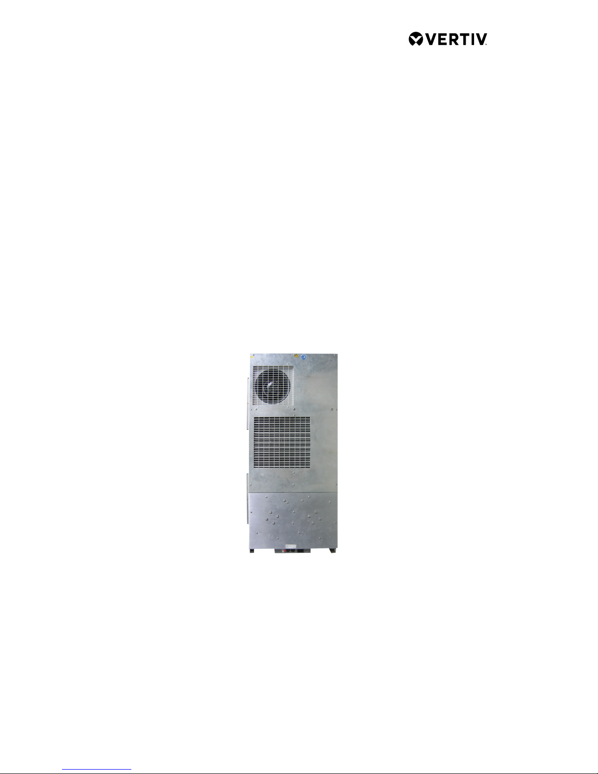
The cooling unit is intended to be used as a complementary accessory to larger industrial
equipment. The unit is used where heat needs to be dissipated from electrical control cabinets or
similar enclosures in order to protect heat sensitive components. It is not intended for household use.
The unit has two completely separate air circuits which ensure that the clean cabinet air does not
come into contact with the ambient air which may well be dirty or polluted. Control cabinet cooling
units can dissipate large quantities of heat from sealed enclosures such as electrical enclosures into
the ambient air and at the same time reduce the cabinet internal temperature to below that of the
ambient air.
The unit can function without problems in extreme ambient conditions (e.g. dusty and oily air) with
a standard operating temperature ranging between -20°C and +55°C. Units can be ordered with an
additional electrical cabinet heater. For the cooling capacities and evironmental ratings please refer to
the type plate data.
5. Technical data
Customer order number 1.920.906.0
Order Number 4020009
Cooling capacity L35L35 1,8 kW
Compressor Rotary piston compressor
Refrigerant / GWP R134a / 1430
Refrigerant charge 650 g / 23 oz
High / low pressure 45 / 44 bar
440 / 140 psig
Temperature range +20°C - +55°C
Mounting External
Housing Material Aluminum
Dimension HxWxD 1,066 x 486 x 157 (173) mm
Weight 36 kg
Voltage / Frequency 230 V ~ 50/60 Hz
Rated current 5.6 A
Current L35L35 5.6 A
Starting current 22 A
Nominal power L35L35 1,22 kW
Max. power 1,25 kW
Fuse 2 x 16 A (T)
Connection Cable
IP class EN 60529 External circuit: IP 44
Internal circuit: IP 55
Approvals CE, cURus, SA32278
Page 5
Version Nr. 1-1 - 23.08.2017 Doc. Nr. 994020009 5 / 14
7. Mounting
Always disconnect the power supply before opening the unit.
Heat load to be dissipated from enclosure should not exceed specific cooling output of the unit at any
condition. At cooling unit selection always cater for a safety margin of at least 15% extra cooling
output in the worst conditions. Air inlets and outlets must be completely free from obstruction.
Ensure that flows of air leaving and entering the cooling unit, internal and external, are not obstructed.
Cooling unit enclosure air suction hole must be installed in the highest possible point. When installing
the unit on a door ensure it can take the weight.
Before drilling the enclosure ensure the fixing elements and couplings will not interfere with the
equipment inside the enclosure itself. Disconnect power before starting any work inside the enclosure.
Following this 1:1 Scale Drilling Template drill the holes and make the required cuts on the enclosure.
This template may have been affected by storage conditions, please check this template by verifying
values of the largest dimensions before drilling. Fit the sealing strip on the cooling unit on the side
connected to the enclosure and follow the installation diagram.
Page 6

Version Nr. 1-1 - 23.08.2017 Doc. Nr. 994020009 6 / 14
8. Electrical connection
High electric voltage present. Installation, maintenance, cleaning and
any other work must be carried out by qualified personnel only. The
personnel must ensure that for the duration of this work the unit and
the cabinet are disconnected from the electrical supply and protected
against unauthorised/accidental reconnection.
Note: As soon as preperations are finished, mounting procedures may proceed.
Connection to the main electrical supply
The mains connection is made via a connector / terminal block. To connect the unit to the mains
proceed as follows:
Take the control cabinet out of operation in the prescribed manner.
●
See the connection details on the circuit diagram.
●
Attention
Between contact 3 & 4 there is a 12V DC potential. These connections are to be connected to a door
switch only! If no door switch is used, these contacts are to be bridged and protected from
unauthorized and/or accidental external contact. Contacts 1 & 2 are potential free and require an
external power source if wired to operate external components (indicator lamps, switches...). The load
on these contacts is not to exceed 30V DC, 4 A or 120/250V AC, 4 A. If wired to external components it
must be ensured that the wiring and connections are double insulated and safe against touch and
protected from unauthorized and/or accidental external contact.
Ensure that the correct polarity is maintained. The fans should have
clockwise rotation.
Fault warning connection
The fault warning is connected via terminals 1 & 2 on the connection terminal block. The temp.
adjustment range is between 25°C (left-hand stop) and 55°C (right-hand stop). The alarm temp. is
preset at 55°C.
To change the alarm setting:
Remove the outer cover.
●
Remove the fixing screws from the PCB cover and the earth wire from inside it.
●
Lift off the PCB cover
●
Using a screwdriver turn the alarm temp. potentiometer on the PC-board slightly to the right (higher)
●
or the left (lower)
please note that the setting for the alarm signal must be at least 5°C higher than the setting for the
●
cabinet's internal temperature
Close the unit as prescribed.
●
Check that the new setting meets requirments and if not repeat the above process.
Door contact switch connection
Page 7

Version Nr. 1-1 - 23.08.2017 Doc. Nr. 994020009 7 / 14
If required the unit can be switched on or off via a door contact switch (terminal 3 & 4). When
delivered the door contact terminals are bridged.
To connect the door contact switch:
Remove the bridge from terminals 3 & 4.
●
Connect the door contact switch to terminals 3 & 4.
●
The contact must be closed when the cabinet door is closed.
●
Page 8

Version Nr. 1-1 - 23.08.2017 Doc. Nr. 994020009 8 / 14
9. Controller Layout Description
FDP_PP Full display port and programming port
AIO Aux. Input optional
HC Heater control
AC Alarm control
TC Temperature control
OS Optional Sensor
DC Door contact
AO Alarm output
PI Power in
CO Compressor out
CC Capacitor compressor
AFO Umgebungslüfter aus
CAF Kondensator Umgebungslüfter
IFO Ambient fan out
CIF Capacitor ambient fan
TB Test button
SDP Simple display port
DP Diagnose port
T Transformer
Page 9

Version Nr. 1-1 - 23.08.2017 Doc. Nr. 994020009 9 / 14
10. Wiring diagram
M1 Radial fan cold side
M2R Radial fan warm side right
M2L Radial fan warm side left
M3 Compressor motor
C1 Capacitor for M1
C2R Capacitor for M2R
C2L Capacitor for M2L
C3 Capacitor for M3
C4 Capacitor for M2L & M2R
X1 Supply connector
X2 Alarm connector
V Varistor
H1 Heater element
FN Neutral line fuse
FL Live line fuse
Temp. Control temperature adjustment potentiometer
Alarm Alarm temperature adjustment potentiometer
Heater Heater temperature adjustment potentiometer
1,2 Alarm contact NC
3,4 Door contact NC
P Power
C Compressor
CC Compressor capacitor
AF Ambient fan
AFC Ambient fan capacitor
IF Internal fan
IFC Internal fan capacitor
TB Test button
N Neutral
L1 Live, 230V
PE Earth
TS Temp. sensor
IS Ice sensor
Temperature settings
PositionTemp °C Alarm °CHeater °C
1 20 25 -5
2 25 30 0
3 30 35 5
4 35 40 10
5 40 45 15
6 45 50 20
7 50 55 25
Page 10

Version Nr. 1-1 - 23.08.2017 Doc. Nr. 994020009 10 / 14
Page 11

Version Nr. 1-1 - 23.08.2017 Doc. Nr. 994020009 11 / 14
11. Taking into operation
Attention!
The unit can be damaged by lack of lubricant. To ensure that the compressor is adequately lubricated
the oil, which has been displaced during transport, must be allowed to flow back into it. The unit must
therefore be allowed to stand for at least 30 min. before being connected to the mains and taken into
operation. Upon connection the internal fan will start working. If the temperature inside the enclosure
is higher than the set value of the controller both the compressor and external air fan start working.
Once the air inside the enclosure reaches the set temperature the compressor and external fan will
stop.
The unit is pre-set at 35°C, which is suitable for most of the electronic devices.
Page 12

Version Nr. 1-1 - 23.08.2017 Doc. Nr. 994020009 12 / 14
12. Trouble shooting
Failure Condition Cause Solution
Unit
doesn't
cool
Internal fan does not work Power not connected. Verify power supply
Internal fan works, external fan
and compressor don't work
Enclosure temperature is
below
setting temperature (St)
Verify values of parameter
"St"
Door switch contact is open Verify door switch
Controller doesn't work Replace controller
Internal fan works, external fan
and compressor don't work.
Display shows alternating OFF
and temperature
The sequence of the phases
inside the power supply
connector is incorrect
Change phases inside
power
supply connector
Unit
doesn't
cool
External and internal fan work,
compressor does not work
Compressor motor electrical
failure
Have compressor replaced
by qualified service
technician
Capacitor for compressor failed Replace capacitor
Compressor works, external fan
doesn't work
External fan needs to be
replaced
Replace external fan
Enclosure
temperature
too hot
Compressor and fans (external
and internal) work all the time
Cooling unit undersized
Enclosure needs a cooling
unit with with higher
capacity
Compressor and external fan
work in alternating mode
(ON / OFF)
Thermal compressor protector
triggered
Verify if ambient
temperature
is too high,clean condenser
Refrigerant leakage Contact dealer/service center
Excessive
condensate
Enclosure door open
Ambient air gets into the
enclosure
Ensure door is closed, add
a door switch and connect
it to controller
Enclosure door closed
Enclosure IP protection class
is below IP54
Seal all openings of the
enclosure
Damaged or misplaced sealing
strip
Repair sealing strip
accordingly
13. Maintenance & Cleaning
Always switch power supply off before starting any maintenance on
the unit.
The cooling unit is generally maintenance free and can be operated without filters in most
environments. For units with filters these should be checked, cleaned and if necessary replaced on a
regular basis. In addition the unit should have regular functional tests (approx. every 2,000 hours
depending on the grade of ambient pollution).
Disposal.
The cooling unit contains R134a refrigerant and small quantities of lubricating oil. Replacement,
repairs and final disposal must be done according to the regulations of each country for these
substances.
14. Transport & Storage
Malfunction due to transport damage
On delivery the carton box containing the unit must be examined for signs of transport damage. Any
transport damage to the carton box could indicate that the unit itself has been damaged in transit
which in the worst case could mean that the unit will not function.
Page 13

Version Nr. 1-1 - 23.08.2017 Doc. Nr. 994020009 13 / 14
The unit can only be stored in locations which meet the following conditions:
temperature range: - 40°C to + 70°C
●
Relative humidity (at 25°C): max. 95 %
●
Returning the unit
To avoid transport damage the unit should be returned in the original packing or in a packing case and
must be strapped to a pallet. If the unit cannot be returned in the original packing please ensure that:
A space of at least 30 mm. must be maintained at all points between the unit and the external
●
packing.
The unit must be shipped in the same position as it was mounted.
●
The unit must be protected by shock resistant padding (hard foam corner pieces, strips or cardboard
●
corner pieces).
Page 14

Version Nr. 1-1 - 23.08.2017 Doc. Nr. 994020009 14 / 14
15. Parts supplied
1 x Outdoor cabinet air conditioner
1 x Instruction manual
1 x CE Conformity declaration
1 x Connector with bridged door contacts
1 x Lid deflector (with fasteners)
1m PVC hose 6x9mm clear soft, flexible
 Loading...