

Page 1

NetSure™ SM-DU+
Supervision Module for Distribution Unit
Plus
Installation and User Manual
Specification Number: 10010507
Model Number: SM-DU+
Page 2

Vertiv™ NetSure™ Supervision Module for Distribution Unit Plus Installation and User Manual
The information contained in this document is subject to change without
notice and may not be suitable for all applications. While every precaution has
been taken to ensure the accuracy and completeness of this document, Vertiv
assumes no responsibility and disclaims all liability for damages resulting from
use of this information or for any errors or omissions. Refer to other local
practices or building codes as applicable for the correct methods, tools, and
materials to be used in performing procedures not specifically described in
this document.
The products covered by this instruction manual are manufactured and/or
sold by Vertiv. This document is the property of Vertiv and contains
confidential and proprietary information owned by Vertiv. Any copying, use or
disclosure of it without the written permission of Vertiv is strictly prohibited.
Names of companies and products are trademarks or registered trademarks of
the respective companies. Any questions regarding usage of trademark
names should be directed to the original manufacturer.
Technical Support Site
If you encounter any installation or operational issues with your product, check the pertinent section of this
manual to see if the issue can be resolved by following outlined procedures.
Visit https://www.vertiv.com/en-us/support/ for additional assistance.
Vertiv™ NetSure™ Supervision Module for Distribution Unit Plus Installation and User Manual
Page 3

Vertiv™ NetSure™ Supervision Module for Distribution Unit Plus Installation and User Manual
iii
TABLE OF CONTENTS
Admonishments Used in this Document ......................................................................................................................... iv
Important Safety Instructions ............................................................................................................................................. v
Static Warning ......................................................................................................................................................................... vi
1 Introduction ......................................................................................................................................................................... 1
1.1 Overview ................................................................................................................................................................................................................................................................................. 1
1.2 Technical Specifications ......................................................................................................................................................................................................................................... 1
2 Switch Settings .................................................................................................................................................................. 3
2.1 General .................................................................................................................................................................................................................................................................................. 3
3 Installation ........................................................................................................................................................................... 5
3.1 Mounting ............................................................................................................................................................................................................................................................................... 5
4 Electrical Connections ..................................................................................................................................................... 5
4.1 Important Safety Instructions ............................................................................................................................................................................................................................ 5
4.2 Wiring Considerations............................................................................................................................................................................................................................................... 5
4.3 Frame Grounding Connection........................................................................................................................................................................................................................... 5
4.4 Load Shunt Input Connections ........................................................................................................................................................................................................................ 6
4.5 Fuse Alarm (FA) Input Connections ........................................................................................................................................................................................................... 6
4.6 Input Power Connections ...................................................................................................................................................................................................................................... 8
4.7 NCU CAN Bus Connections ................................................................................................................................................................................................................................ 9
5 Operation ............................................................................................................................................................................ 11
5.1 Indicators ............................................................................................................................................................................................................................................................................ 11
5.2 Configuring the NCU SM-DU+ Parameters........................................................................................................................................................................................ 12
Page 4
Vertiv™ NetSure™ Supervision Module for Distribution Unit Plus Installation and User Manual
iv
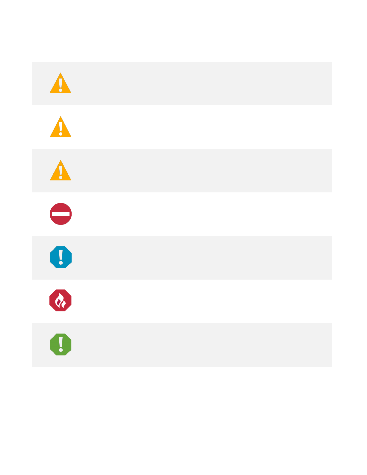
DANGER!
in death or serious injury if not avoided. (ANSI, OSHA)
WARNING!
result in
death or
risk only to equipment, software, data, or service. (ANSI)
CAUTION!
result in minor or moderate injury if not avoided. (ANSI, OSHA) This admonition is not
used for situations that pose a risk only to equipment, data, or service, even if such use
appears to be permitted in some of the applicable standards. (OSHA)
ALERT!
equipment, software, data, or service. (ISO)
ALERT!
equipment damage, software corruption, data lo
FIRE SAFETY!
or policies, or of the locations of fire
SAFETY!
policies not related to a particular source of hazard or to fire safety. (ISO, ANSI, OSHA)
Admonishments Used in this Document
Warns of a hazard the reader
Warns of a potential hazard the reader
serious injury if not avoided. This admonition is not used for situations that pose a
Warns of a potential hazard the reader
Alerts the reader to an action that
will
be exposed to that will
may
be exposed to that
may
be exposed to that
must be avoided
likely
result
could
could
in order to protect
Alerts the reader to an action that
Informs the reader of fire safety information, reminders, precautions,
Informs the reader of general safety information, reminders, precautions, or
-fighting and fire-safety equipment. (ISO)
must be performed
ss, or service interruption. (ISO)
in order to prevent
Page 5

Vertiv™ NetSure™ Supervision Module for Distribution Unit Plus Installation and User Manual
v
Important Safety Instructions
Safety Admonishments Definitions
Definitions of the safety admonishments used in this document are listed under “Admonishments Used in this Document” on page iv.
General Safety
DANGER! YOU MUST FOLLOW APPROVED SAFETY PROCEDURES.
Performing the following procedures may expose you to hazards. These procedures should be performed by qualified
technicians familiar with the hazards associated with this type of equipment. These hazards may include shock, energy,
and/or burns. To avoid these hazards:
a) The tasks should be performed in the order indicated.
b) Remove watches, rings, and other metal objects.
c) Prior to contacting any uninsulated surface or termination, use a voltmeter to verify that no voltage or the expected
voltage is present. Check for voltage with both AC and DC voltmeters prior to making contact.
d) Wear eye protection.
e) Use certified and well maintained insulated tools. Use double insulated tools appropriately rated for the work to be
performed.
Personal Protective Equipment (PPE)
DANGER! ARC FLASH AND SHOCK HAZARD.
Appropriate PPE and tools required when working on this equipment. An appropriate flash protection boundary analysis
should be done to determine the “hazard/risk” category, and to select proper PPE.
Only authorized and properly trained personnel should be allowed to install, inspect, operate, or maintain the equipment.
Do not work on LIVE parts. If required to work or operate live parts, obtain appropriate Energized Work Permits as required
by the local authority, per NFPA 70E “Standard for Electrical Safety in the Workplace”.
Handling Equipment Containing Static Sensitive Components
ALERT! Installation or removal of equipment containing static sensitive components requires careful handling. Before
handling any equipment containing static sensitive components, read and follow the instructions contained on the Static
Warning Page.
Page 6

Vertiv™ NetSure™ Supervision Module for Distribution Unit Plus Installation and User Manual
vi
Static Warning
This equipment contains static sensitive components. The warnings listed below must be observed to prevent damage to
these components. Disregarding any of these warnings may result in personal injury or damage to the equipment.
1. Strictly adhere to the procedures provided in this document.
2. Before touching any equipment containing static sensitive components, discharge all static electricity from yourself by
wearing a wrist strap grounded through a one megohm resistor. Some wrist straps have a built-in one megohm resistor;
no external resistor is necessary. Read and follow wrist strap manufacturer’s instructions outlining use of a specific wrist
strap.
3. Do not touch traces or components on equipment containing static sensitive components. Handle equipment
containing static sensitive components only by the edges that do not have connector pads.
4. After removing equipment containing static sensitive components, place the equipment only on static dissipative
surfaces such as conductive foam or ESD bag. Do not use ordinary Styrofoam or ordinary plastic.
5. Store and ship equipment containing static sensitive components only in static shielding containers.
6. If necessary to repair equipment containing static sensitive components, wear an appropriately grounded wrist strap,
work on a conductive surface, use a grounded soldering iron, and use grounded test equipment.
Page 7
Vertiv™ NetSure™ Supervision Module for Distribution Unit Plus Installation and User Manual
1
SM-DU+ Assembly
1 Introduction
1.1 Overview
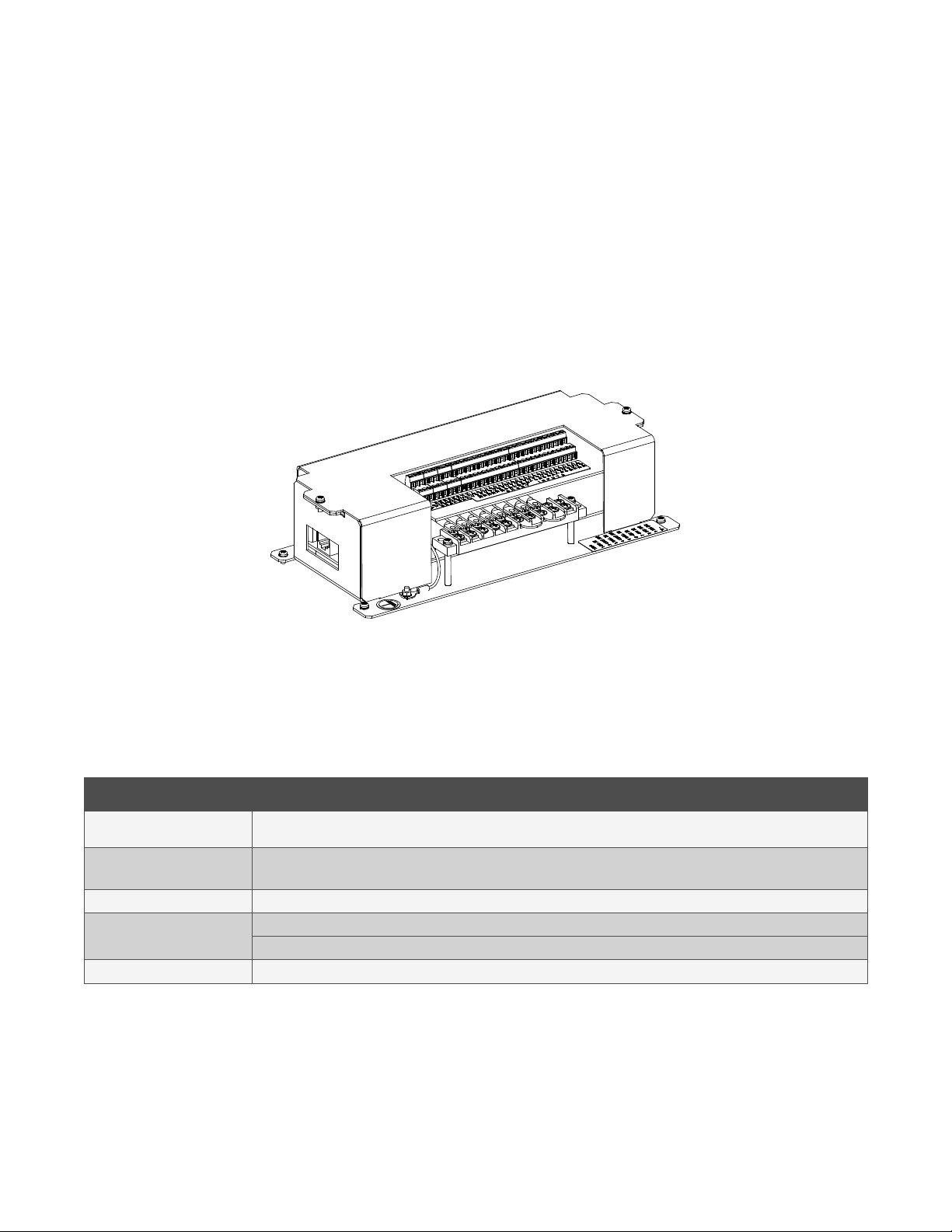
This assembly consists of an SM-DU+ enclosed in a sheet metal housing. This assembly is used in applications where an SM-DU+ is
mounted external to a power system equipped with an NCU controller. The SM-DU+ assembly is used to connect load shunts and
fuse alarm signals to the NCU controller. The SM-DU+ assembly provides twenty-five (25) load shunt monitoring inputs and fourteen
(14) fuse alarm monitoring inputs.
The SM-DU+ assembly connects into the NCU CAN bus. Up to eight (8) SM-DU+ assemblies can be connected to an NCU. Refer to
Figure 1-1 for an illustration of the SM-DU+ assembly.
Figure 1-1: SM-DU+ Assembly
1.2 Technical Specifications
See Table 1-1.
Table 1-1: Technical Specifications
Item Description
Operating Voltage
Operating
Temperature Range
Communication CAN Bus
Input Signals
Dimensions
Nominal: -48 VDC.
Input Voltage Range: -19 VDC to -60 VDC.
Normal Operation Temperature Range: -10°C to +65°C.
Non Destructive Range: -40°C to +75°C.
Fourteen (14) Fuse Alarm (Bus- base of 0 VDC, >10 VDC alarm, <10 VDC normal).
Twenty-Five (25) Load Shunts (25 mV DC to 75 mV DC Shunt)
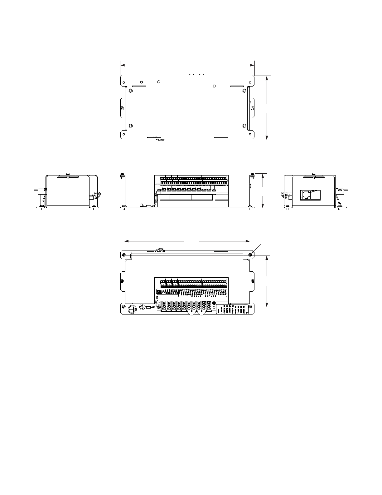
See Figure 1-2.
Page 8
Vertiv™ NetSure™ Supervision Module for Distribution Unit Plus Installation and User Manual
2
10.00
4.76
9.43
3.86
Diameter 0.14” (4-places)
2.57
Notes:
1. All dimensions are in inches,
unless otherwise specified.
Front
Bottom
Top
Left Side Right Side
Figure 1-2: Dimensions
Page 9
Vertiv™ NetSure™ Supervision Module for Distribution Unit Plus Installation and User Manual
3
Switch SW2
Switch SW1
SW1
SW2
on
5678
123
4
off
on
5
678
1
234
off
Power
CAN
RS485RS485
RS232
SW1
SW2
J1
J7
ShuntShunt
J8
J6
Fuse
J3
J4
J4A
J5
ON
OFF
Green Indicator
8 7 6 5 4 3 2 1
8 7 6 5 4 3 2 1
SM-DU+ Circuit Board
2 Switch Settings
2.1 General
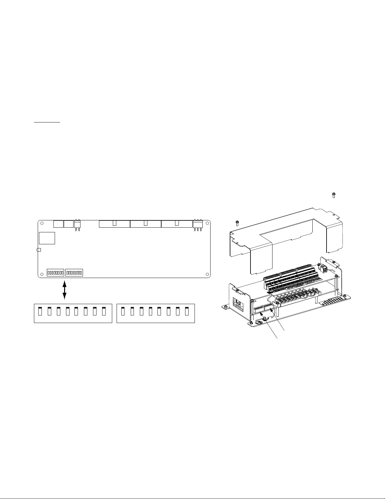
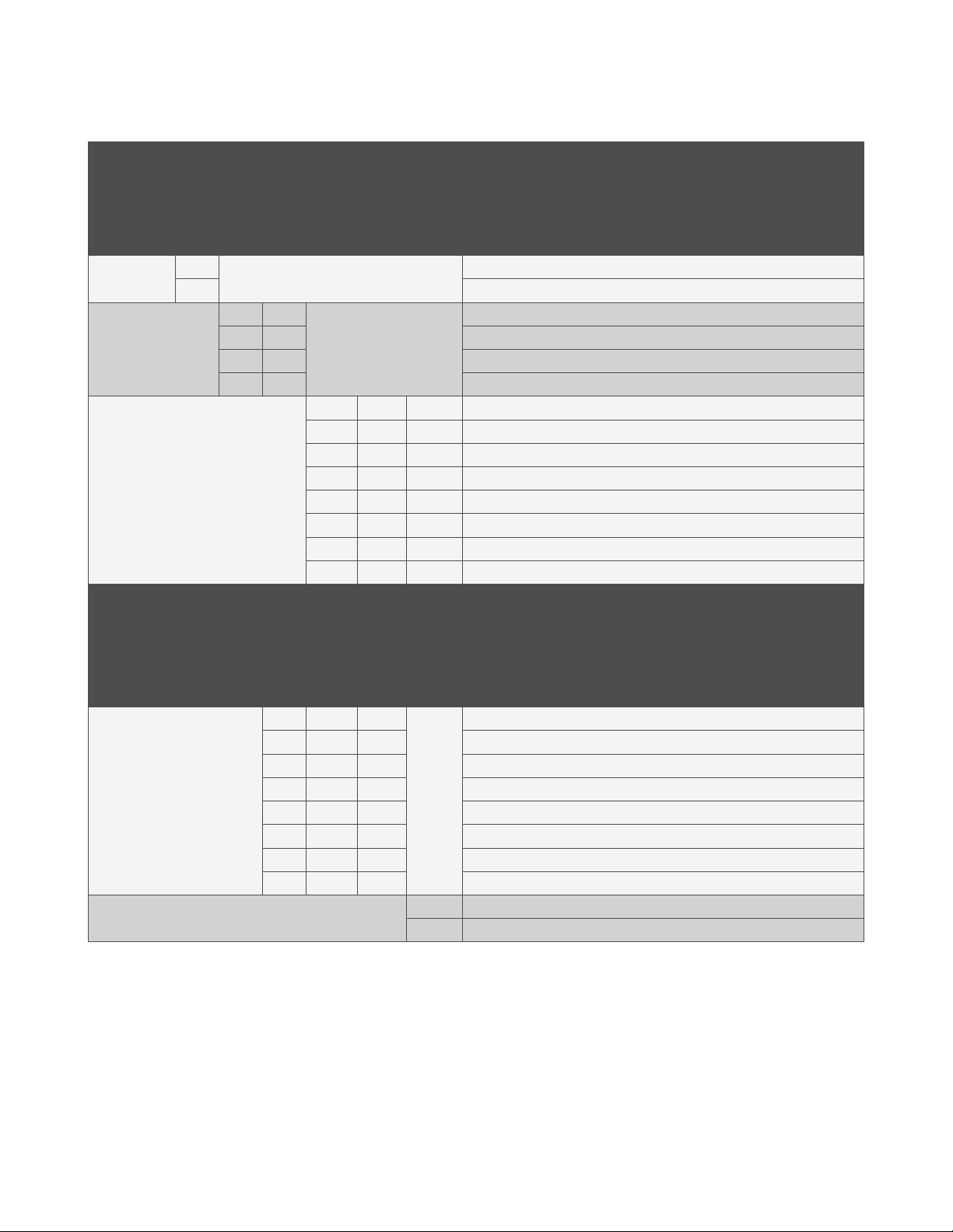
The SM-DU+ assembly uses two (2) 8-bit switches for parameter settings (SW1 and SW2). Refer to Figure 2-1 for SW1 and SW2
locations. Refer to Table 2-1 for SW1 and SW2 settings.
Perform the following procedure to make switch setting adjustments.
Procedure
1. Remove the top cover to access the switches.
2. Set SW1 and SW2 per site requirements. Refer to Figure 2-1 for location. See Table 2-1 for setting descriptions. (Set the
addressing switches on each SM-DU+ assembly installed in the system to a unique address per Table 2-1.)
Figure 2-1: SM-DU+ Assembly Switch Locations
Page 10
Vertiv™ NetSure™ Supervision Module for Distribution Unit Plus Installation and User Manual
4
(note 1)
(note 1)
(note 1)
(Setting for 1st SM-DU+ in System)
(Setting for 2nd SM-DU+ in System)
(Setting for 3rd SM-DU+ in System)
(Setting for 4th SM-DU+ in System)
(Setting for 5th SM-DU+ in System)
(Setting for 6th SM-DU+ in System)
(Setting for 7th SM-DU+ in System)
(Setting for 8th SM-DU+ in System)
(note 1)
Table 2-1: SM-DU+ Switch Settings
DIP Switch SW1
Reserved
1 2 3 4 5 6 7 8
NA
DIP Switch SW2
HW/S
Shunt Voltage
W
OFF
ON Shunt parameter is set through software
OFF OFF
NA
Reserved Communications Address
OFF ON Shunt Voltage: 50mV
ON OFF Shunt Voltage: 60mV
ON ON Shunt Voltage: 75mV
OFF OFF OFF Shunt Current: 500 A
OFF OFF ON Shunt Current: 100 A
OFF ON OFF Shunt Current: 200 A
NA
OFF ON ON Shunt Current: 300 A
Shunt
Current
NA
NA
ON OFF OFF Shunt Current: 400 A
ON OFF ON Shunt Current: 1000 A
ON ON OFF Shunt Current: 1500 A
ON ON ON Shunt Current: 2000 A
Baud
Rate
Description of Status
Shunt parameter is set through DIP switch.
Shunt Voltage: 25mV
Description of Status
.
1 2 3 4 5 6 7 8
OFF OFF OFF
OFF OFF ON Address 2#
OFF ON OFF Address 3#
NA
OFF ON ON Address 4#
ON OFF OFF Address 5#
ON OFF ON Address 6#
ON ON OFF Address 7#
ON ON ON Address 8#
NA
Note 1: Default Setting
Address 1#
NA
OFF 19200
ON 9600
Page 11
Vertiv™ NetSure™ Supervision Module for Distribution Unit Plus Installation and User Manual
5
SM-DU+ Assembly Top View
Frame Ground
(Torque to 6 in-lbs.)
3 Installation
3.1 Mounting
The SM-DU+ assembly provides mounting holes in each corner. Refer to Figure 1-2 for location and dimensions.
4 Electrical Connections
4.1 Important Safety Instructions
DANGER! Adhere to the “Important Safety Instructions” starting on page v.
4.2 Wiring Considerations
All wiring should follow the current edition of the American National Standards Institute (ANSI) approved National Fire Protection
Association's (NFPA) National Electrical Code (NEC), and applicable local codes. For operation in countries where the NEC is not
recognized, follow applicable codes.
4.3 Frame Grounding Connection
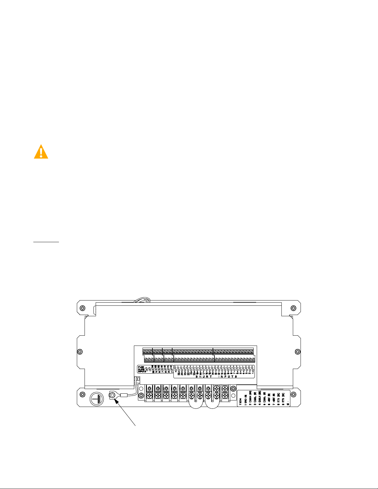
A frame ground stud (M3) is located on the outside of the SM-DU+ assembly.
Procedure
1. Connect a frame ground lead to the frame ground stud located on the SM-DU+ assembly. Refer to Figure 4-1 for location.
Recommended torque is 6 in-lbs.
Figure 4-1: SM-DU+ Assembly Frame Grounding Connection
Page 12
Vertiv™ NetSure™ Supervision Module for Distribution Unit Plus Installation and User Manual
6
Connect to SM-DU+ FA InputConnect to -48 VDC
External Fuse Alarm
Form-C Relay Contact
NO
COM
NC
X
4.4 Load Shunt Input Connections
The SM-DU+ assembly provides connections for up to twenty-five (25) load shunt inputs.
See also “Switch Settings” on page 3.
Procedure
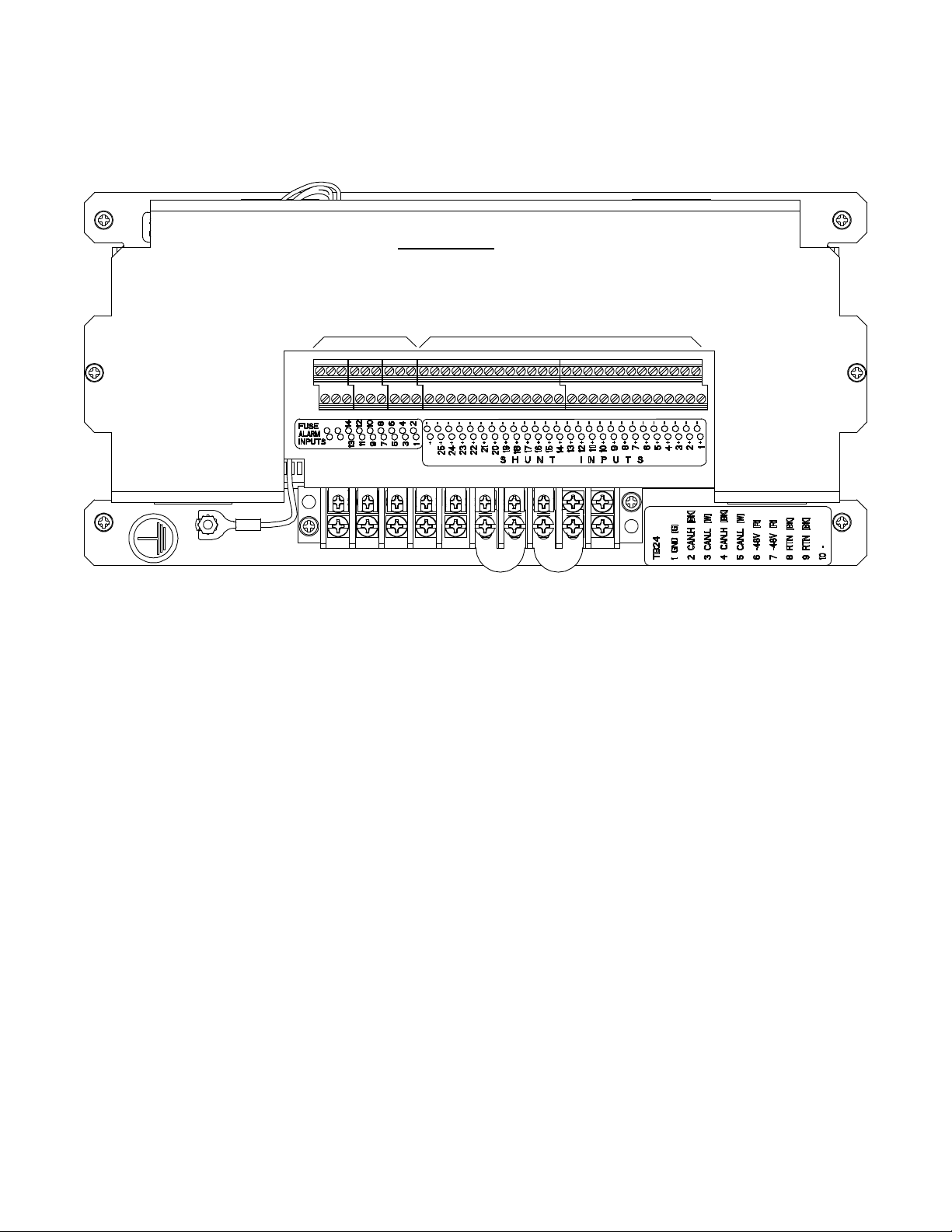
1. Connect up to twenty-five (25) load shunt inputs to the SM-DU+ assembly. Observe proper polarity. Refer to Figure 4-2 and
the label on the SM-DU+ assembly for connection point identification.
NOTE!
on the SM-DU+ assembly. Connect the negative side of the shunt to the negative shunt input on the SM-DU+ assembly.
The shunt needs to be installed in the hot (-48V) bus. Connect the plus side of the shunt to the positive shunt input
4.5 Fuse Alarm (FA) Input Connections
The SM-DU+ assembly provides connections for up to fourteen (14) fuse alarm (FA) inputs.
Procedure
1. Connect up to fourteen (14) fuse alarm (FA) inputs to the SM-DU+ assembly. Refer to Figure 4-2 and the label on the SM-
DU+ assembly for connection point identification.
- When a -48 VDC signal is applied to a fuse alarm input, the associated fuse alarm is inactive.
- When a -48 VDC signal is removed from a fuse alarm input, the associated fuse alarm is active.
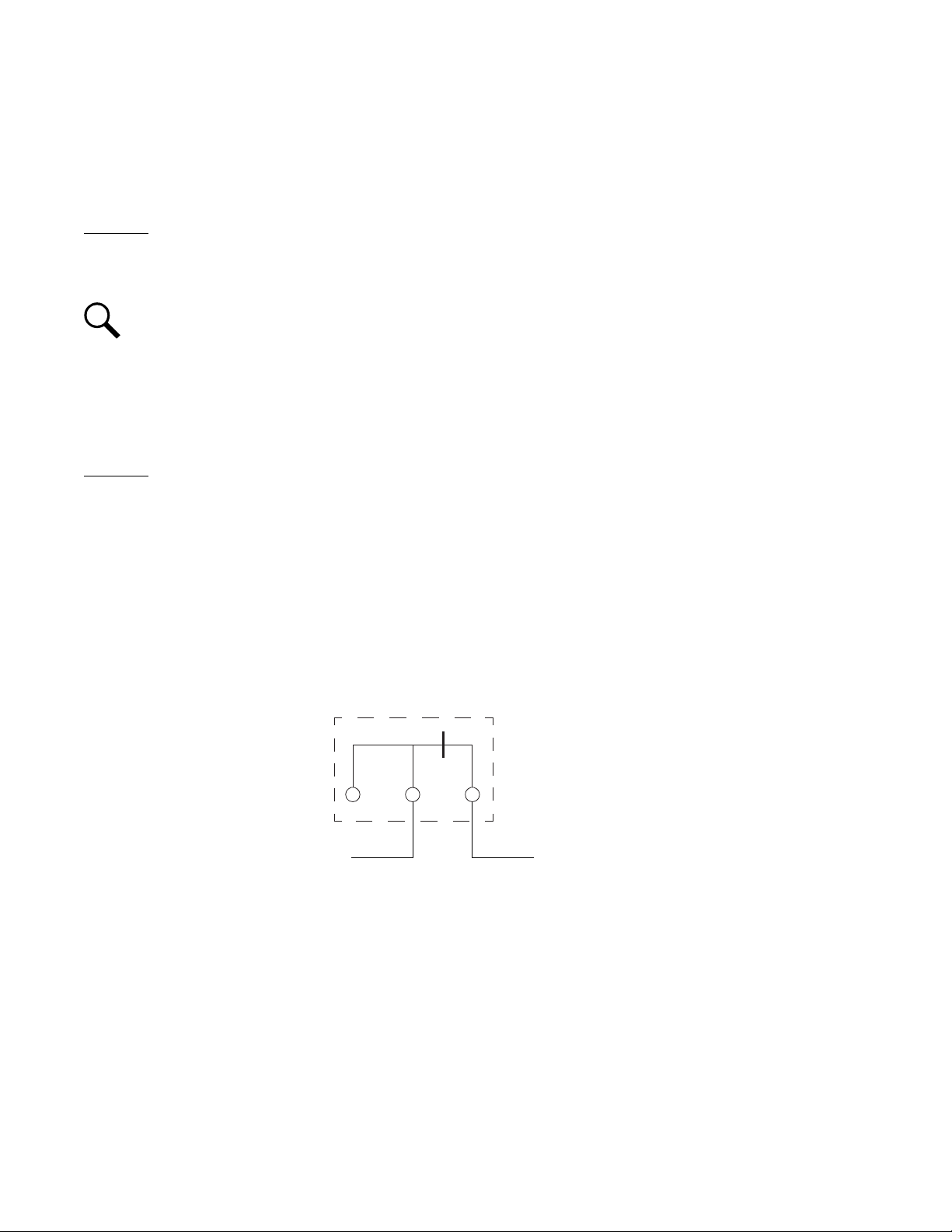
It is suggested to use an external fuse alarm Form-C relay contact. Connect the common (COM) terminal of the external fuse
alarm Form-C relay to a -48 VDC source and connect the normally closed (NC) terminal of the external fuse alarm Form-C
relay to one of the SM-DU+ FA inputs, as shown below.
2. Any of the fourteen (14) fuse alarms not being used needs to have their severity set to NA to indicate that this fuse alarm
input is not being used. Refer to the NCU manual for details.
Page 13
Vertiv™ NetSure™ Supervision Module for Distribution Unit Plus Installation and User Manual
7
Terminal Blocks
Wire Size Capacity: 16-26 AWG.
Recommended Torque: 2.2 in-lbs.
SM-DU+ Assembly Top View
FUSE ALARM
INPUTS
SHUNT
INPUTS
(+Shunt)
(-Shunt)
Figure 4-2: SM-DU+ Assembly Shunt and Fuse Alarm (FA) Inputs Connections
Page 14
Vertiv™ NetSure™ Supervision Module for Distribution Unit Plus Installation and User Manual
8
Screw: #6-32 Philslot
Recommended Lug: #6 Spade
Distance between Barriers: 0.30”
Torque: 9.0 in-lbs.
Use cable P/N 557012 to connect -48V and RTN
to the SM-DU+ Assembly.
-48V: Red Wire
RTN: Black W ire
-48V: Red Wire RTN: Black W ire
SM-DU+ Assembly Top View
P/N 557012 Cable Assembly (provided)
4.6 Input Power Connections
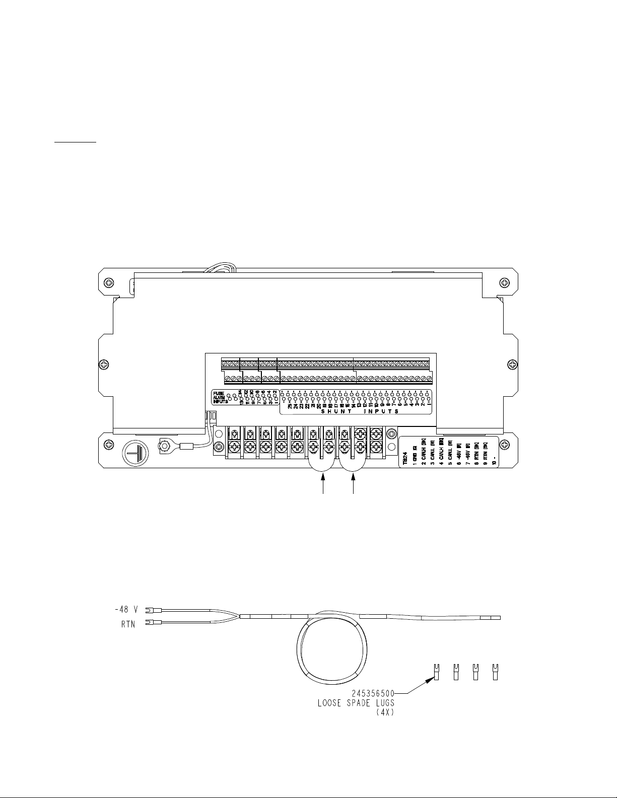
Input power must be supplied to each SM-DU+ assembly installed in the system. A cable is factory provided for this connection. The
ungrounded input lead should be fused at 1 ampere. Refer to Figure 4-3 for input power connection location.
Procedure
1. Connect the spade lug end of cable P/N 557012 provided to the appropriate terminals located on the SM-DU+ assembly (see
Figure 4-3.). Red to a -48V terminal, Black to a RTN terminal.
2. Route this cable to the input power source. Cut this cable to length and terminate it with the supplied spade lugs. Connect
Red to the -48V power source terminal. Connect Black to a RTN power source terminal.
Figure 4-3: SM-DU+ Assembly Input Power Connections
Page 15
Vertiv™ NetSure™ Supervision Module for Distribution Unit Plus Installation and User Manual
9
4.7 NCU CAN Bus Connections
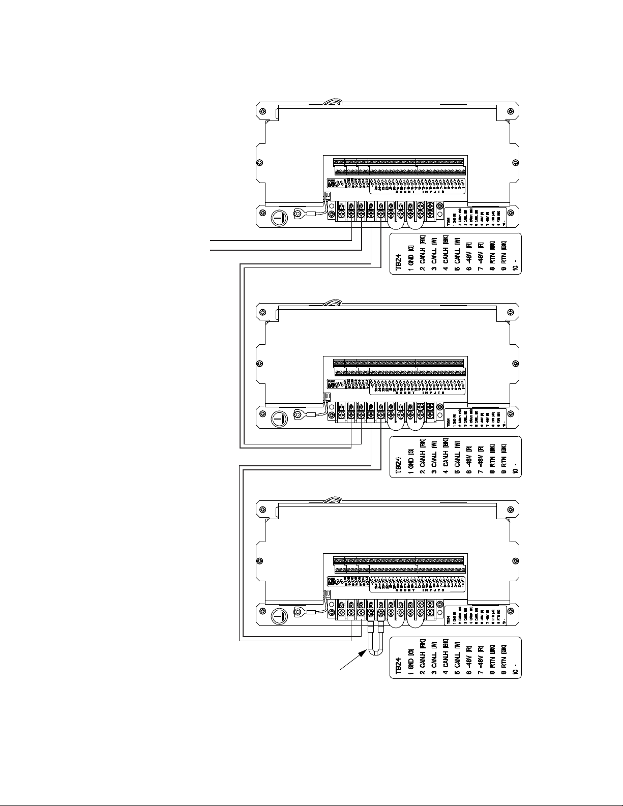
Refer to Figure 4-4.
Procedure (Connecting First SM-DU+ Assembly to NCU)
1. Connect the SM-DU+ assembly into the NCU CAN Bus. Connect CAN_H to CAN_H. Connect CAN_L to CAN_L. Refer to the
system documentation for NCU CAN port description and location. Cable P/N 562868 provided. Refer to Table 4-1 for cable
information. Refer to Figure 4-4 for an interconnect diagram.
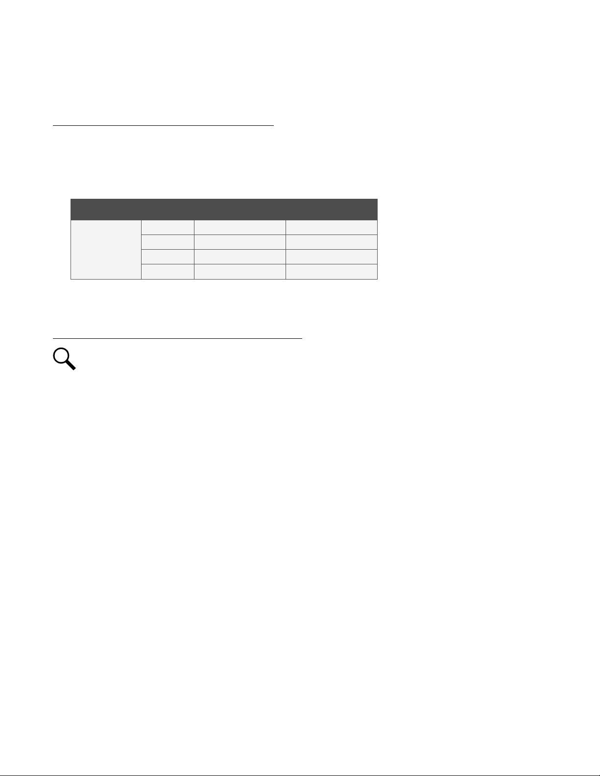
Table 4-1: CAN Bus Cable P/N 562868
Connector Pin No. Color Signal Symbol
1 W/O CAN_L
RJ-45
* For use with NetSure 8200 and NetSure 802 retrofit kits.
2 O CAN_H
4* BL CAN_H
5* W/BL CAN_L
Procedure (Connecting Multiple SM-DU+ Assemblies Together)
NOTE!
The NCU can communicate with up to eight (8) SM-DU+ assemblies. Set each SM-DU+ assembly to a unique
address number.
1. To connect multiple SM-DU+ assemblies together, for all assemblies connect the CAN_H terminals together and connect the
CAN_L terminals together (CAN_H to CAN_H, CAN_L to CAN_L). See Figure 4-4 for an interconnect diagram.
2. Connect a termination resistor such as P/N 561768 to the last SM-DU+ assembly in the NCU CAN bus. Connect to CAN_H
and CAN_L terminals along with the CAN_H and CAN_L leads factory connected to the terminal block. See Figure 4-4.
Page 16
Vertiv™ NetSure™ Supervision Module for Distribution Unit Plus Installation and User Manual
10
To power system’s
CAN L Terminal.
To power system’s
CAN H Terminal.
Screw: #6-32 Philslot
Recommended Lug: #6 Spade
Distance between Barriers: 0.30”
Torque: 9.0 in-lbs.
SM-DU+ Assembly Top View
SM-DU+ Assembly Top View
SM-DU+ Assembly Top View
Remove the termination
resistor from power system
CAN bus terminal block and
place it here (or use P/N
561768 termination resistor).
Cable P/N 562868 provided.
Twisted Wire Pair
CAN_H to CAN_H
CAN_L to CAN_L
Twisted Wire Pair
CAN_H to CAN_H
CAN_L to CAN_L
Figure 4-4: SM-DU+ Assembly CAN Bus Connections
Page 17
Vertiv™ NetSure™ Supervision Module for Distribution Unit Plus Installation and User Manual
11
Green Indicator
5 Operation
The SM-DU+ assembly monitors load shunt inputs and fuse alarm inputs and reports this data to the NCU controller.
5.1 Indicators
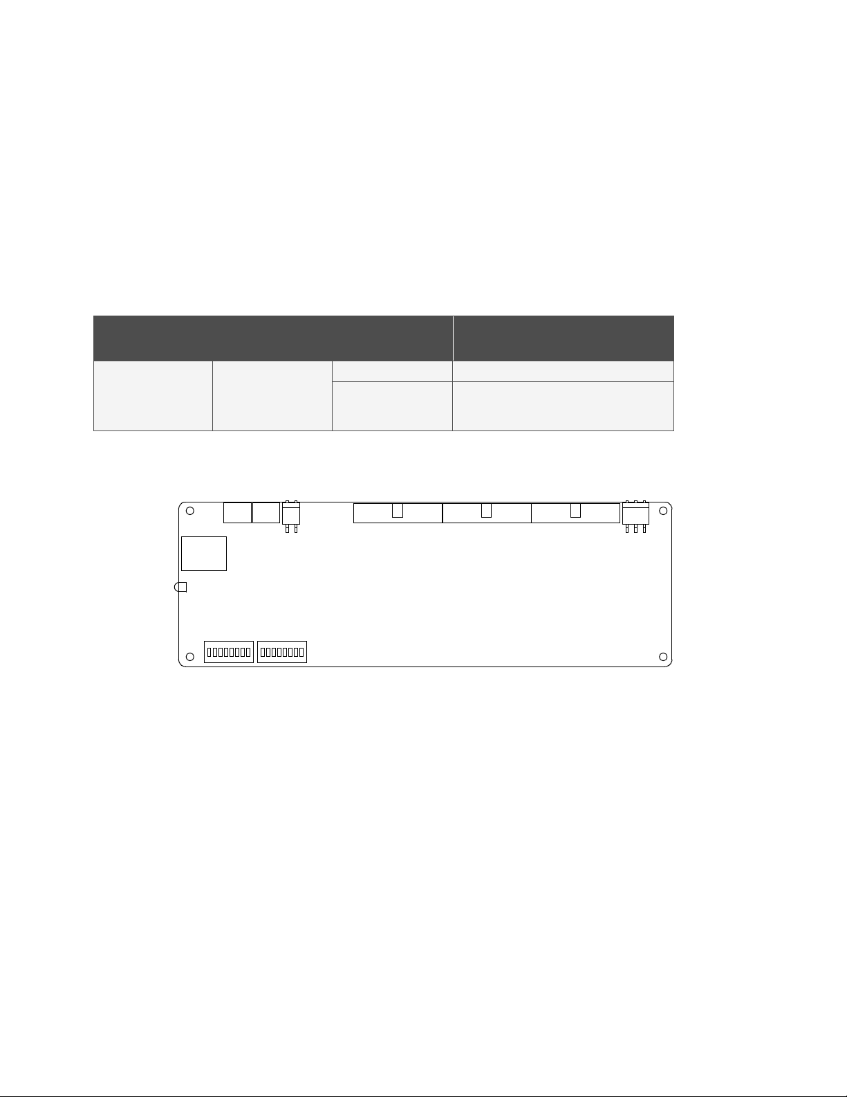
There is one (1) status and alarm indicator located on the SM-DU+ circuit card. The function of this indicator is as shown in Table 5-1.
Refer to Figure 5-1 for location.
Table 5-1: SM-DU+ Circuit Card Indicator
Indicator Normal State Fault State Fault Cause
Off SM-DU+ is non-operational.
Operation
(Green)
On
Flashing
A 1/3Hz flashing indicates the SM-DU+ is being
identified by the Controller.
A 1Hz flashing indicates a communication failure.
Figure 5-1: SM-DU+ Circuit Card Indicator Location
Page 18

Vertiv™ NetSure™ Supervision Module for Distribution Unit Plus Installation and User Manual
12
5.2 Configuring the NCU SM-DU+ Parameters
Refer to the NCU controller manual (UM1M830BNA) for detailed instructions on how to program the monitored inputs to the SM-DU+
assembly.
Page 19

Vertiv™ NetSure™ Supervision Module for Distribution Unit Plus Installation and User Manual
Connect with Vertiv on Social Media
https://www.facebook.com/vertivI
https://www.instagram.com/vertiv/
https://www.linkedin.com/company/vertiv/
https://www.twitter.com/vertiv/
Page 20

Vertiv.com | Vertiv Headquarters, 1050 Dearborn Drive, Columbus, OH, 43085, USA
© 2020 Vertiv Group Corp. All rights reserved. Vertiv™ and the Vertiv logo are trademarks or registered trademarks of Vertiv Group
Corp. All other names and logos referred to are trade names, trademarks or registered trademarks of their respective owners. While
every precaution has been taken to ensure accuracy and completeness here, Vertiv Group Corp. assumes no responsibility, and
disclaims all liability, for damages resulting from use of this information or for any errors or omissions. Specifications, rebates and
other promotional offers are subject to change at Vertiv’s sole discretion upon notice.
UM10010507_REVB
 Loading...