

Page 1
NetSure™ 7100
Ordering Guide
Compact DC Power System
582137100101-106
Page 2
NetSure™ 7100 Ordering Guide
Description
The modular NetSure™ 7100 Compact Series 19”W power system with 3500 watt rectifiers provides up to 500 amps of current for -48
volt systems in 6RU of space for outdoor applications or 8RU of space for indoor applications. The basic components of the power
system include the NetSure Control Unit (NCU), module mounting shelves which house the rectifiers, and a distribution cabinet.
Low voltage disconnect options can be included for load shedding, discharge time improvement and battery health.
Click on a page number below to jump to that page. To return to the Table of Contents, click on the header of any page.
Table of Contents
Step 1. Choose Power System ........................................................................................2
Step 2. Optional - 19" or 23" Relay Rack ..............................................................................3
Step 3. Choose Distribution Devices ..................................................................................3
Step 4. Choose Controller ............................................................................................5
Step 5. Optional - Choose Controller Interfaces .......................................................................6
Step 6. Optional - Choose Battery Tray Kits and Battery Lug Kits .....................................................6
Step 7. Optional - Choose Accessories ...............................................................................7
Step 8. Choose Rectifiers ...........................................................................................7
Note: All of the above items ship loose and must be installed in the field by the end user.
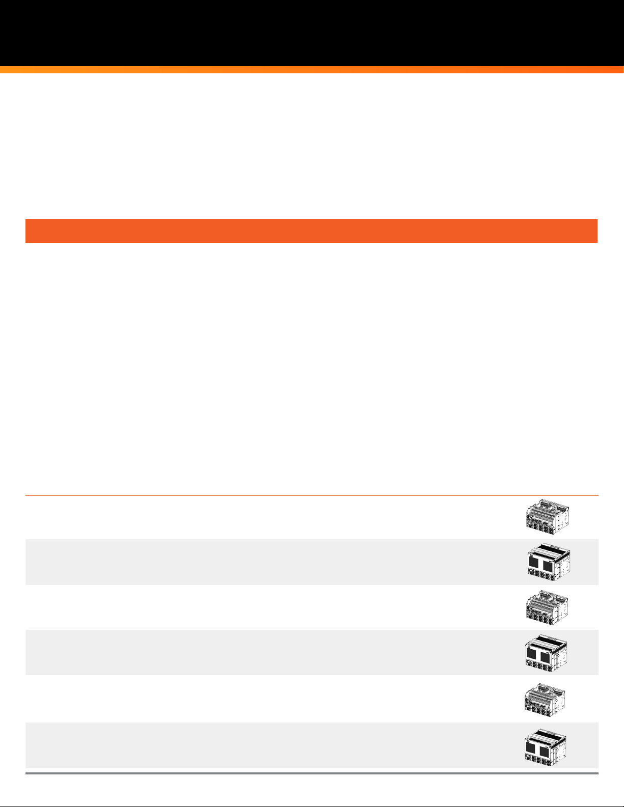
Step 1. Choose Power System
Select one, quantity of one.
Vertiv™ Part Number Description Qt y.
582137100101
582137100102
582137100103
582137100104
582137100105 -48 VDC 500 A Power System e/w LVBD. 6RU
-48 VDC 500 A Power System e/w (2)
LVLD and LVBD.
-48 VDC 500 A Power System e/w
(2) LVLD and LVBD.
-48 VDC 500 A Power System e/w
no LVD's.
-48 VDC 500 A Power System e/w
no LVD's.
Rack
Space
6RU
8RU
6RU
8RU
Notes Pictorial
For Outdoor Cabinet Installation. No front
door and top cover. (21) load
circuit breaker positions.
For Indoor applications (21) load circuit
breaker positions.
For Outdoor Cabinet Installation. No front
door and top cover. (21) load
circuit breaker positions.
For Indoor applications (21) load circuit
breaker positions.
For Outdoor Cabinet Installation. No front
door and top cover.
582137100106 -48VDC 500A Power System e/w LVBD. 8RU
Vertiv™ | NetSure™ 7100 Ordering Guide | (RA04/20) 2
For Indoor applications (21) load circuit
breaker positions.
Page 3

Step 2. Optional - 19"W or 23"W Relay Rack
Select one, quantity of one.
Vertiv™ Part Number Description Qt y.
559824 Relay rack, 84.000”H x 21.000”W x 15”D 45RU 19" - Welded
559823 Relay rack, 84.000”H x 20.375”W x 15”D 45RU 19" - Seismic
563922 Relay rack, 84.000”H x 21.800”W x 18”D 45RU 19" - Seismic e/w 6" rails
559817 Relay rack, 51.906”H x 24.376”W x 15”D 28RU
559818 Relay rack, 72.000”H x 24.375”W x 15”D 37RU
559820 Relay rack, 84.000”H x 24.375”W x 15”D 45RU
559819 Relay rack, 84.000”H x 25.000”W x 15”D 45RU
562353 Relay rack, 84.000”H x 25.800”W x 18”D 45RU
559821 Relay rack, 90.000”H x 24.375”W x 15”D 48RU
559822 Relay rack, 96.000”H x 24.375”W x 15”D 51RU
Rack
Space
Notes Pictorial
23" - Welded. Requires 19" to 23"W
adapter for mounting power system.
23" - Welded. Requires 19" to 23"W
adapter for mounting power system.
23" - Welded. Requires 19" to 23"W
adapter for mounting power system.
23" - Seismic. Requires 19" to 23"W
adapter for mounting power system.
23" - Seismic e/w 6" rails. Requires 19"
to 23"W adapter for mounting
power system.
23" - Welded. Requires 19" to 23"W
adapter for mounting power system.
23" - Welded. Requires 19" to 23"W
adapter for mounting power system.
Step 3. Choose Distribution Devices
Step 3a. Choose Bullet-Nose Type Circuit Breakers
Vertiv™ Part Number Ampere Rating Description Qty Notes Pictorial
Electrical Trip Toggle Handle Bullet Breakers
102272 1 White toggle handle Occupies one position
102273 3 White toggle handle Occupies one position
102274 5 White toggle handle Occupies one position
102275 10 White toggle handle Occupies one position
102276 15 White toggle handle Occupies one position
102277 20 White toggle handle Occupies one position
102278 25 White toggle handle Occupies one position
102279 30 White toggle handle Occupies one position
102280 35 White toggle handle Occupies one position
102281 40 White toggle handle Occupies one position
121998 45 White toggle handle Occupies one position
102282 50 White toggle handle Occupies one position
102283 60 White toggle handle Occupies one position
102284 70 White toggle handle Occupies one position
102285 75 White toggle handle Occupies one position
121996 80 White toggle handle Occupies one position
138887 90 White toggle handle Occupies one position
102286 100 White toggle handle Occupies one position
516991 125 White toggle handle Occupies two positions
3Vertiv™ | NetSure™ 7100 Ordering Guide | (RA04/20)
Page 4

NetSure™ 7100 Ordering Guide
Step 3a. (Continued)
Vertiv™ Part Number Ampere Rating Description Qty Notes Pictorial
Electrical Trip Toggle Handle Bullet Breakers
516993 150 White toggle handle Occupies two positions
144883 175 White toggle handle Occupies two positions
121831 200 White toggle handle Occupies two positions
144885 225 White toggle handle Occupies three positions
121835 250 White toggle handle Occupies three positions
149075 300 White toggle handle Occupies three positions
Vertiv™ Part Number Ampere Rating Description Qty Notes Pictorial
Electrical/Mechanical Trip Toggle Handle Bullet Breakers
101596 1 Black toggle handle Occupies one position
101597 3 Black toggle handle Occupies one position
101598 5 Black toggle handle Occupies one position
101599 10 Black toggle handle Occupies one position
101600 15 Black toggle handle Occupies one position
101601 20 Black toggle handle Occupies one position
101602 25 Black toggle handle Occupies one position
101603 30 Black toggle handle Occupies one position
101604 35 Black toggle handle Occupies one position
101605 40 Black toggle handle Occupies one position
121997 45 Black toggle handle Occupies one position
101606 50 Black toggle handle Occupies one position
101607 60 Black toggle handle Occupies one position
101608 70 Black toggle handle Occupies one position
101609 75 Black toggle handle Occupies one position
121995 80 Black toggle handle Occupies one position
138888 90 Black toggle handle Occupies one position
101610 100 Black toggle handle Occupies one position
516838 125 Black toggle handle Occupies two positions
516839 150 Black toggle handle Occupies two positions
144884 175 Black toggle handle Occupies two positions
121832 200 Black toggle handle Occupies two positions
144886 225 Black toggle handle Occupies three positions
121836 250 Black toggle handle Occupies three positions
149076 300 Black toggle handle Occupies three positions
Vertiv™ | NetSure™ 7100 Ordering Guide | (RA04/20)
4
Page 5

Step 3b. Choose Bullet-Nose Type Bypass Bus Bar
Vertiv™ Part Number Description Qty Notes Pictorial
535015 Bullet Nose Bypass Busbar Occupies one position
Step 3c. Choose Lug Adapters
Vertiv™ Part Number Description Qty Notes Pictorial
563191 Two pole lug adapter Required for two pole breaker, one each for hot and return.
563193 Three pole lug adapter Required for three pole breaker, one each for hot and return.
Step 4. Choose Controller
Select one, quantity of one.
Vertiv™ Part Number Description Qty Notes Pictorial
1M830BNA10009548
1M830BNA10008994
1M830BNA10008996
NCU Controller for 582137100101 and 102.
(1) LVBD and (2) LVLD.
NCU Controller for 582137100103 and 104.
No LVD’s.
NCU Controller for 582137100105 and
106. LVBD.
5Vertiv™ | NetSure™ 7100 Ordering Guide | (RA04/20)
Page 6

NetSure™ 7100 Ordering Guide
Step 5. Optional - Controller Interfaces
Vertiv™ Part Number Description Qty Notes Pictorial
556155
552992
04119122 10 m temperature probe extension Provides 10 meter extension for temperature probe.
552822 0.3m temperature probe Temperature sensor, spare part.
547490 SMTEMP, 8 input temperature module
565458 SM Temp to CAN connection cable, 25-ft.
431300200
431300300
Temperature probe, 3.3m, includes
0.3 m sensor
Temperature probe, 10.3m, includes
0.3m sensor
1 amp in-line fuse pigtail kit with 3/8"
ring lug
1 amp in-line fuse pigtail kit with 5/16"
ring lug
Provides temperature monitoring and alarming for
battery or ambient. Battery-assigned probes provide
temperature compensation and battery thermal
runaway management.
Provides temperature monitoring and alarming for
battery or ambient. Battery-assigned probes provide
temperature compensation and battery thermal
runaway management.
Provides (8) temperature inputs. Maximum quantity of
eight per system. Mounts external to power system.
Used for connecting to battery or bus potentials for
use with digital inputs on the IB2 Interface board or
battery midpoint inputs on the EIB card.
Used for connecting to battery or bus potentials for
use with digital inputs on the IB2 Interface board or
battery midpoint inputs on the EIB card.
Step 6. Optional - Battery Tray Kit & Battery Lug Kits
Vertiv Part Number Description Qty Notes Pictorial
Includes 100A battery disconnect breaker and battery
582137100SK001
588820200SK001
588820200SK002
588820200SK004
19"W Battery tray assembly with 100A
battery disconnect.
23"W Battery tray assembly with 100A
battery disconnect.
23"W Battery tray assembly with 150A
battery disconnect.
23"W Battery tray assembly with 200A
battery disconnect.
disconnect breaker box. Tray, battery disconnect
breaker and battery disconnect box are all assembled in
the field. Battery cable included. Mounts in a 19"W relay
rack. 22.5" depth. Tray is dark gray in color.
Includes 100A battery disconnect breaker and battery
disconnect breaker box. Tray, battery disconnect
breaker and battery disconnect box are all assembled in
the field. Battery cable included. Mounts in a 23"W relay
rack. 22.5" depth. Tray is dark gray in color.
Includes 150A battery disconnect breaker and battery
disconnect breaker box. Tray, battery disconnect
breaker and battery disconnect box are all assembled in
the field. Battery cable included. Mounts in a 23"W relay
rack. 22.5" depth. Tray is dark gray in color.
Includes 200A battery disconnect breaker and
battery disconnect breaker box. Tray, battery
disconnect breaker and battery disconnect box are all
assembled in the field. Battery cable included. Mounts in
a 23"W relay rack. 22.5" depth. Tray is dark gray in color.
Vertiv™ | NetSure™ 7100 Ordering Guide | (RA04/20)
6
Page 7

Vertiv™ Part Number Description Qty Notes Pictorial
528234
528236
528235
528237
2 AWG 90 degree short tongue battery
lug kit
2 AWG 90 degree long tongue battery
lug kit
1/0 AWG 90 degree short tongue battery
lug kit
1/0 AWG 90 degree long tongue battery
lug kit
Step 7. Optional - Accessories
Vertiv™ Part Number Description Qty Notes Pictorial
553630 6RU 19"W to 23" W Relay Rack Adapter Kit
565533 Wall Mount Bracket Kit
SXA1100035/1 Rectifier Blank Cover Panel
362736700 Relay Rack Cable Bracket
562977 Earthquake Anchor Kit
Step 8. Order Rectifiers
See instruction manuals for de-rating information due to temperature
Slots for (9) rectifiers in each power system.
Vertiv™ Part Number Description Qty Notes Pictorial
1R483500E3
Please SAV E this form to your desktop. Then email the completed form to: AccountManagement.ESNA@Vertiv.com
Contact your local sales representative with questions or call 1-800-800-1280 for support.
Rectifier, R48-3500e3, 48VDC, 3500 watts,
high efficiency, 1 RU
Provides 72.9 amps at -48VDC
SUBMIT
7Vertiv™ | NetSure™ 7100 Ordering Guide | (RA04/20)
Page 8

Vertiv.com | Vertiv Headquarters, 1050 Dearborn Drive, Columbus, OH, 43085, USA
© 2020 Vertiv G roup Corp. All right s reserved. Vertiv ™ and the Vertiv logo are tr ademarks or regis tered trademarks of Ver tiv Group Corp. All o ther names and log os referred to are trade n ames, trademar ks or registered tra demarks of their res pective owners . While every
precauti on has been taken to en sure accuracy and c ompleteness he re, Vertiv Group Cor p. assumes no resp onsibility, and dis claims all liabili ty, for damages resu lting from use of this inf ormation or for any erro rs or omissions . Specificatio ns, rebates and oth er promotional
oers are su bject to change at Ver tiv’s sole discret ion upon notice.
DC- 00115 (RA04/20)
 Loading...