

Page 1

Liebert®
Mini-Mate2™ ThermalManagementSystem
Installer/User Guide
2-ton and 3-ton Capacity, 50 and 60Hz
Page 2

The information contained in this document is subject to change without notice
and may not be suitable for all applications. While every precaution has been
taken to ensure the accuracy and completeness of this document, Vertiv
assumes no responsibility and disclaims all liability for damages resulting from
use of this information or for any errors or omissions. Refer to other local
practices or building codes as applicable for the correct methods, tools, and
materials to be used in performing procedures not specifically described in this
document.
The products covered by this instruction manual are manufactured and/or sold
by Vertiv. This document is the property of Vertiv and contains confidential
and proprietary information owned by Vertiv. Any copying, use or disclosure of
it without the written permission of Vertiv is strictly prohibited.
Names of companies and products are trademarks or registered trademarks of
the respective companies. Any questions regarding usage of trademark names
should be directed to the original manufacturer.
Technical Support Site
If you encounter any installation or operational issues with your product, check the pertinent section of this
manual to see if the issue can be resolved by following outlined procedures.
Visit https://www.Vertiv.com/en-us/support/ for additional assistance.
Vertiv | Li ebert® Mini-Mate2™ Installer/Us er Guide
Page 3

TABLE OF CONTENTS
1 Important Safety Instructions 1
1.1 Agency Listed 6
2 Nomenclature 7
2.1 Nomenclature for Evaporator and Chilled Water Units 7
2.2 Nomenclature for Split System Condensing Units 9
2.2.1 Indoor Condensing Units for Air Cooled Split Systems 9
2.2.2 Outdoor Prop Fan Condensing Units for Air Cooled Split Systems 10
2.2.3 Water/Glycol-cooled Condensing Units 11
2.3 System Configurations 12
3 Site Preparation and Equipment Handling 15
3.1 Planning Dimensions 15
3.2 Room Preparation 15
3.2.1 Duct Work Considerations for the Indoor Air Cooled Condensing Unit 15
3.3 Application Limits 16
3.4 Indoor Unit Weights 17
3.5 Location Considerations 18
3.5.1 Location Considerations for Evaporator, Indoor Condensing,andChilled WaterUnits 18
3.5.2 Location Considerations for an Outdoor Condensing Unit 19
3.6 Equipment Inspection and Handling 19
3.7 Packaging Material 19
4 Installation 21
4.1 Installing Ceiling Mounted EvaporatorsandCondensing Units 21
4.1.1 Installing Suspension Rods andMounting Ceiling Units 21
4.1.2 Close Coupled Installations forIndoorCondensingUnits 23
4.2 Installing Air Distribution Components for Evaporators 24
4.2.1 Installing a Plenum 24
4.2.2 Installing a Filter Box 24
4.2.3 Guidelines for Ducted Systems 25
5 Piping and Refrigerant Requirements 27
5.1 Fluid Piping Required 28
5.1.1 Drain Line Installation Requirements 28
5.1.2 Condensate Drain Pump Kit 30
5.1.3 Water Supply Line to the Humidifier 31
5.1.4 Chilled Water Loop Piping 31
5.1.5 Water/Glycol Loop Piping 32
5.1.6 Free Cooling Coil Piping 33
5.1.7 Hot Water Reheat Coil Piping 33
5.2 Refrigerant Piping 34
i
Page 4

5.2.1 Piping when Condensing Unit is Above or Below Evaporator 35
5.2.2 Refrigerant Line Sizes and Equivalent Lengths 36
5.2.3 Refrigerant Charge Requirements 37
5.2.4 Field Fabricated Refrigeration Piping 39
5.2.5 Evacuation and Leak Testing Air Cooled Systems 39
5.2.6 Charging Air Cooled Systems 41
5.2.7 Field Charge Verification forAir Cooled Systems 42
5.2.8 Documenting Refrigerant Charge on AirCooled Units 42
5.2.9 Evacuation and Leak-testing Water/Glycol-cooled Systems 43
5.2.10 Charging Water/Glycol-cooled Systems 45
5.2.11 Optimizing Refrigerant Charge on Water/Glycol Units 46
5.2.12 Documenting Refrigerant Charge on Water/Glycol Cooled Units 46
6 Electrical Connection Requirements 47
6.1 Input Power Connection Requirements 48
6.2 Control Wiring Connection Requirements 49
6.2.1 Wall Box Controller Control Connections 49
6.2.2 Split-system Condensing-unit Control Connections 49
6.2.3 Water/Glycol Cooled Unit Control Connections 49
6.2.4 Additional Control Connections 49
7 Checklist for Completed Installation 51
8 Initial Start up Checks andCommissioningProcedure forWarrantyInspection 53
9 Microprocessor Control 55
9.1 Controller Operation 55
9.1.1 Powering On/Off with Wall Mounted Display 56
9.1.2 Silencing an Audible Alarm 56
9.2 Main Menu <MENU> 57
9.2.1 To Select a Menu Option 57
9.2.2 Main Menu Options 57
9.2.3 Editing Setpoints 60
9.2.4 Viewing Unit Status 60
9.2.5 Viewing Active Alarms 61
9.2.6 Setting Controller Time 61
9.2.7 Setting Controller Date 61
9.2.8 Programming Setback 61
9.2.9 Editing Setup Operation 62
9.2.10 Changing Setpoint and Setup Passwords 64
9.2.11 Calibrating Sensors and Setting Sensor Response Delay 64
9.2.12 Enabling/Disabling Alarms 65
9.2.13 Setting Alarm Delays 65
9.2.14 Activating the Common Alarm Relay 66
ii
Vertiv | Li ebert® Mini-Mate2™ Installer/Us er Guide
Page 5

9.2.15 Configuring Custom Alarms 67
9.2.16 Customizing Alarm Message Text 67
9.2.17 LCD Display Contrast 67
9.2.18 Non-Volatile Memory 67
9.2.19 Equipment Options DIP Switches 68
9.3 Running Diagnostics 68
9.3.1 Showing Test Inputs 68
9.3.2 Testing Outputs 69
9.3.3 Testing the Microcontroller 70
9.4 System Control and Performance 72
9.4.1 Temperature Control 73
9.4.2 Reheat 73
9.4.3 Humidity Control 74
9.4.4 Load Control 75
9.4.5 Monitoring 75
9.5 Alarm Notification, Acknowledgment, and Descriptions 76
9.5.1 Custom Alarms 76
9.5.2 High Head Pressure Alarm 76
9.5.3 Humidity Level Alarms 77
9.5.4 Temperature Level Alarms 77
9.5.5 High Water Alarm 77
9.5.6 Loss of Power Alarm 77
9.5.7 Short Cycle Alarm 77
9.5.8 Loss of Water Flow Alarm 78
9.5.9 Change Filter Alarm 78
9.5.10 High Temperature Alarm 78
9.5.11 Smoke Alarm 78
10 Maintenance 79
10.1 System Testing 80
10.1.1 Environmental Control Function Tests 80
10.1.2 Cooling Test 80
10.1.3 Heating Test 80
10.1.4 Humidification Test 80
10.1.5 Dehumidification Test 80
10.1.6 Smoke Sensor Test 80
10.1.7 Remote Shutdown Test 81
10.2 Filter Maintenance 81
10.3 Electric Panel Maintenance 81
10.4 Direct Drive Blower Package Maintenance 81
10.4.1 Fan Impeller and Motor Bearing Maintenance 81
iii
Page 6

10.4.2 Motor Replacement 81
10.4.3 Air Distribution Inspection 81
10.4.4 Removing the Blower from the Evaporator 81
10.4.5 High Static, Belt Drive Blower Package (Option) Maintenance 82
10.4.6 Belt Maintenance 82
10.5 Electric Reheat Maintenance 82
10.6 Refrigeration System Maintenance 83
10.6.1 Refrigeration Suction Pressure 83
10.6.2 Refrigeration Discharge Pressure 83
10.6.3 Thermostatic Expansion Valve (TXV) Maintenance 83
10.6.4 Air Cooled Condensing Unit Maintenance 83
10.6.5 Hot Gas Bypass Operation and Maintenance 84
10.6.6 Coaxial Condenser Maintenance (Water/Glycol Cooled Condensers Only) 86
10.6.7 Regulating Valve Maintenance (Water/Glycol Cooled Condensers Only) 86
10.6.8 Glycol Solution Maintenance 86
10.7 Compressor Maintenance 87
10.7.1 Mechanical Failure of the Compressor 87
10.7.2 Electrical Failure of the Compressor 87
10.7.3 Replacement Compressors 88
10.7.4 Replacing a Failed Compressor 88
10.8 Steam Generating Humidifier Maintenance 88
10.8.1 Operating the Humidifier 89
10.8.2 Replacing the Canister 90
10.8.3 Circuit Board Adjustments 90
11 Preventive Maintenance Checklist 93
12 Troubleshooting 99
Appendices 103
Appendix A: Technical Support and Contacts 103
Appendix B: Submittal Drawings 105
iv
Vertiv | Li ebert® Mini-Mate2™ Installer/Us er Guide
Page 7

1 IMPORTANT SAFETY INSTRUCTIONS
SAVE THESE INSTRUCTIONS
This manual contains important safety instructions that should be followed during the installation and maintenance of the
Liebert®Mini-Mate2. Read this manual thoroughly before attempting to install or operate this unit.
Only qualified personnel should move, install or service this equipment.
Adhere to all warnings, cautions, notices and installation, operating and safety instructions on the unit and in this manual.
Follow all installation, operation and maintenance instructions and all applicable national and local building, electrical and
plumbing codes.
WARNING! Arc flash and electric shock hazard. Open all local and remote electric power-supply disconnect
switches, verify with a voltmeter that power is Off and wear appropriate, OSHA-approved personal protective
equipment (PPE) per NFPA 70E before working within the electric control enclosure. Failure to comply can
cause serious injury or death. Customer must provide earth ground to unit, per NEC, CEC and local codes, as
applicable. Before proceeding with installation, read all instructions, verify that all the parts are included and
check the nameplate to be sure the voltage matches available utility power. The Liebert® controller does not
isolate power from the unit, even in the “Unit Off” mode. Some internal components require and receive
power even during the “Unit Off” mode of the controller. The only way to ensure that there is NO voltage
inside the unit is to install and open a remote disconnect switch. Refer to unit electrical schematic. Follow all
local codes.
WARNING! Risk of electric shock. Can cause equipment damage, injury or death. Open all local and remote
electric power supply disconnect switches and verify with a voltmeter that power is off before working within
any electric connection enclosures. Service and maintenance work must be performed only by properly
trained and qualified personnel and in accordance with applicable regulations and manufacturers’
specifications. Opening or removing the covers to any equipment may expose personnel to lethal voltages
within the unit even when it is apparently not operating and the input wiring is disconnected from the
electrical source.
WARNING! Risk of over pressurization of the refrigeration system. Can cause piping rupture, explosive
discharge of high pressure refrigerant, loss of refrigerant, environmental pollution, equipment damage,
injury, or death. This unit contains fluids and gases under high pressure. Use extreme caution when
charging the refrigerant system. Do not pressurize the system higher than the design pressure marked on
the unit's nameplate. Relieve pressure before cutting into or making connections/disconnections to the
piping system. Local building or plumbing codes may require installing a pressure-relief device in the
system.
Consult local building and plumbing codes for installation requirements of additional pressure-relief devices
when isolation valves are field installed. Do not isolate any refrigerant circuits from over pressurization
protection. The PFH condensing units include a factory installed pressure relief valve mounted on top of the
receiver. The valve is rated for a maximum working pressure of 475 psig.
1 Important Safety Instructions
1
Page 8

WARNING! Risk of contact with high-speed, rotating fan blades. Can cause injury or death. Open all local and
remote electric power-supply disconnect switches, verify with a voltmeter that power is off, and verify that all
fan blades have stopped rotating before working in the unit cabinet.
WARNING! Risk of electric shock. Can cause serious injury or death. The microprocessor does not isolate
power from the unit, even in the "Unit Off" mode. Some internal components require and receive power even
during the "unit off" mode of the control. Open all local and remote electric power disconnect switches and
verify with a voltmeter that power is Off before working on any component of the system.
WARNING! Risk of improper wiring, piping, moving, lifting and handling. Can cause equipment damage,
serious injury or death. Installation and service of this equipment should be done only by qualified personnel,
wearing appropriate, OSHA-approved PPE, who have been specially-trained in the installation of airconditioning equipment.
WARNING! Risk of improper wire and loose electrical connections. Can cause overheated wire and electrical
connection terminals resulting in smoke, fire, equipment and building damage, injury or death. Use correctly
sized copper wire only and verify that all electrical connections are tight before turning power On. Check all
electrical connections periodically and tighten as necessary.
WARNING! Risk of ceiling collapse and heavy unit falling. Can cause building and equipment damage, serious
injury or death. Verify that the supporting roof structure is capable of supporting the weight of the unit(s)
and the accessories. See Indoor Unit Weights on page17, for the unit weights. Securely anchor the top ends
of the suspension rods and verify that all nuts are tight.
WARNING! Risk of smoke and fire. Can cause activation of fire suppression systems, building evacuation,
dispatching of fire/rescue equipment and personnel and catastrophic canister failure resulting in water
leaks, equipment damage, injury or death. Using a humidifier canister that has reached the end of it’s service
life can be extremely hazardous. If the canister cannot be replaced immediately at the end of life condition,
turn Off the power and water supply to the humidifier and remove the canister until a replacement canister
can be installed. Do not ignore humidifier problem alarms. Resetting humidifier without addressing cause
may result in fire or damage due to leaking water.
CAUTION: Risk of excessive refrigerant line pressure. Can cause tubing and component rupture resulting in
equipment damage and personal injury. Do not close off any field installed refrigerant-line isolation valve for
repairs unless a pressure-relief valve is field- installed in the line between the isolation valve and the check
valve. The pressure-relief valve must be rated 5% to 10% higher than the system-design pressure. An
increase in ambient temperature can cause the pressure of the isolated refrigerant to rise and exceed the
system-design pressure rating (marked on the unit nameplate).
2
Vertiv | Li ebert® Mini-Mate2™ Installer/Us er Guide
Page 9

NOTICE
CAUTION: Risk of contact with sharp edges, splinters, and exposed fasteners. Can cause injury. Only
properly trained and qualified personnel wearing appropriate, OSHA-approved PPE should attempt to move,
lift, remove packaging from or prepare the unit for installation.
CAUTION: Risk of contact with hot surfaces. Can cause injury. The compressor, refrigerant discharge lines,
fan motor, and some electrical components are extremely hot during unit operation. Allow sufficient time for
them to cool to a touch-safe temperature before working within the unit cabinet. Use extreme caution and
wear appropriate, OSHA-approved PPE when working on or near hot components.
CAUTION: Risk of contact with hot surfaces. Can cause burn injury. The humidifier canister and steam
discharge lines are extremely hot during operation. Allow sufficient time for them to cool to a touch-safe
temperature before handling. Use extreme caution and wear appropriate, OSHA-approved PPE when
performing maintenance on the humidifier.
CAUTION: Risk of contacting caustic substances. Can cause injury. Avoid touching or contacting the gas and
oils with exposed skin. Severe burns will result. Wear appropriate, OSHA-approved PPE when handling
contaminated parts.
Risk of oil contamination with water. Can cause equipment damage.
Liebert®Mini-Mate2DX systems require the use of POE (polyolester) oil. POE oil absorbs water at a much
faster rate when exposed to air than previously used oils. Because water is the enemy of a reliable refrigeration
system, extreme care must be used when opening systems during installation or service. If water is absorbed
into the POE oil, it will not be easily removed and will not be removed through the normal evacuation process. If
the oil is too wet, it may require an oil change. POE oils also have a property that makes them act as a solvent
in a refrigeration system. Maintaining system cleanliness is extremely important because the oil will tend to
bring any foreign matter back to the compressor.
1 Important Safety Instructions
3
Page 10

NOTICE
NOTICE
Risk of clogged or leaking drain lines and leaking water supply lines. Can cause equipment and building
damage.
This unit requires a water drain connection. Drain lines must be inspected at start-up and periodically, and
maintenance must be performed to ensure that drain water runs freely through the drain system and that lines
are clear and free of obstructions and in good condition with no visible sign of damage or leaks. This unit may
also require an external water supply to operate.
Improper installation, application and service practices can result in water leakage from the unit. Water
leakage can result in catastrophic and expensive building and equipment damage and loss of critical data
center equipment.
Do not locate unit directly above any equipment that could sustain water damage.
We recommend installing a monitored fluid-detection system to immediately discover and report coolant fluid
system and condensate drain line leaks.
Risk of leaking water/glycol. Can cause equipment and building damage.
Improper installation, application, and service practices can result in water leakage from the unit. Do not mount
this unit over equipment and furniture that can be damaged by leaking water. Install a water-tight drain pan
with a drain connection under the cooling unit and the ceiling mounted water/glycol condensing unit. Route the
drain line to a frequently-used maintenance sink so that running water can be observed and reported in a
timely manner. Post a sign to alert people to report water flowing from the secondary drain pan. We
recommend installing monitored leak detection equipment for the unit and supply lines and in the secondary
drain pan. Check drain lines periodically for leaks, sediment buildup, obstructions, kinks and/or damage and
verify that they are free running.
4
Vertiv | Li ebert® Mini-Mate2™ Installer/Us er Guide
Page 11

NOTICE
Risk of piping system corrosion and freezing fluids. Can cause leaks resulting in equipment and very expensive
building damage. Cooling coils and piping systems are at high risk of freezing and premature corrosion. Fluids
in these systems must contain the proper antifreeze and inhibitors to prevent freezing and premature coil and
piping corrosion. The water or water/glycol solution must be analyzed by a competent local water treatment
specialist before start up to establish the inhibitor and antifreeze solution requirement and at regularly
scheduled intervals throughout the life of the system to determine the pattern of inhibitor depletion.
The complexity of water/glycol solution condition problems and the variations of required treatment programs
make it extremely important to obtain the advice of a competent and experienced water treatment specialist
and follow a regularly scheduled coolant fluid system maintenance program.
Water chemistry varies greatly by location, as do the required additives, called inhibitors, that reduce the
corrosive effect of the fluids on the piping systems and components. The chemistry of the water used must be
considered, because water from some sources may contain corrosive elements that reduce the effectiveness of
the inhibited formulation. Sediment deposits prevent the formation of a protective oxide layer on the inside of
the coolant system components and piping. The water/coolant fluid must be treated and circulating through
the system continuously to prevent the buildup of sediment deposits and or growth of sulfate reducing
bacteria.
Proper inhibitor maintenance must be performed in order to prevent corrosion of the system. Consult glycol
manufacturer for testing and maintenance of inhibitors.
Commercial ethylene glycol, when pure, is generally less corrosive to the common metals of construction than
water itself. It will, however, assume the corrosivity of the water from which it is prepared and may become
increasingly corrosive with use if not properly inhibited.
NOTICE
NOTICE
We recommend installing a monitored fluid-detection system that is wired to activate the automatic-closure of
field installed coolant fluid supply and return shut-off valves to reduce the amount of coolant fluid leakage and
consequential equipment and building damage. The shut-off valves must be sized to close-off against the
maximum coolant fluid system pressure in case of a catastrophic fluid leak.
Risk of frozen pipes and corrosion from improper coolant mixture. Can cause water leaks resulting in
equipment and building damage.
When piping or the cooling unit may be exposed to freezing temperatures, charge the system with the proper
percentage of glycol and water for the coldest design ambient temperature. Automotive antifreeze is
unacceptable and must NOT be used in any glycol fluid system. Use only HVAC glycol solution that meets the
requirements of recommended industry practices.
Risk of no flow condition. Can cause equipment damage. Do not leave the water/coolant fluid-supply circuit in a
no flow condition. Idle fluid allows the collection of sediment that prevents the formation of a protective oxide
layer on the inside of tubes. Keep unit switched On and water/coolant fluid supply circuit system operating
continuously.
1 Important Safety Instructions
5
Page 12

NOTICE
NOTICE
NOTICE
NOTICE
Risk of improper water supply. Can reduce humidifier efficiency or obstruct humidifier plumbing.
Do not use completely demineralized water with this unit. The water must contain minerals for the electrode
principle to work.
Do not use a hot water source. It will cause deposits that will eventually block the fill-valve opening.
Risk of water backing up in the drain line. Leaking and overflowing water can cause equipment and building
damage.
Do not install an external trap in the drain line. This line already has a factory installed trap inside the cabinet.
Installation of a second trap will prevent drain water flow and will cause the water to overflow the drain pan.
This line may contain boiling water. Use copper or other material that is rated for handling boiling water for the
drain line. Sagging condensate drain lines may inadvertently create an external trap.
Risk of doorway/hallway interference. Can cause unit and/or structure damage. The unit may be too large to fit
through a doorway or hallway while on the skid. Measure the unit and passageway dimensions, and refer to the
installation plans prior to moving the unit to verify clearances.
Risk of damage from forklift. Can cause unit damage. Keep tines of the forklift level and at a height suitable to
fit below the skid and/or unit to prevent exterior and/or underside damage.
NOTICE
Risk of improper storage. Can cause unit damage.
Keep the unit upright, indoors and protected from dampness, freezing temperatures and contact damage.
1.1 Agency Listed
Standard 60-Hz units are CSA Certified to the harmonized U.S. and Canadian product safety standard CSA C22.2 No
236/UL 1995 for “Heating and Cooling Equipment” and are marked with the CSA c-us logo.
6
Vertiv | Li ebert® Mini-Mate2™ Installer/Us er Guide
Page 13
2 NOMENCLATURE
This section describes the model-number configuration for Liebert® Mini-Mate2 units and components.
2.1 Nomenclature for Evaporator and Chilled Water Units
Table 2.2 below describes each digit of the model number.
Table 2.1 Nomenclature Example
1 2 3 4 5 6 7 8 9 10 11 12
M M D 3 6 E N P R E D 5
Table 2.2 Nomenclature Digit Definitions for Evaporator and Chilled Water Units
Digit Description
Digits 1 and 2 = the base unit
MM = Mini-Mate2
Digit3 = Disconnect
D = Disconnect switch
Digit4 a nd 5 = Nominal Capacity
24 = 24kBtuh, 60Hzevaporator
35 = 35 kBtuh, 50Hz evaporator
36 = 36 kBtuh, 60Hz evaporator
39 = 39 kBtuh, 3-ton, 50Hz, chilled water
40 = 40 kBtuh, 3-ton, 60Hz, chilled water
2 Nomenclature
Digit6 = Cooling type
C = Chilled-water cooled
E = Split-system evaporator (See Nomenclature for Split System Condensing Units on page9.)
K = Split-system evaporator with free cooling (See Nomenclature for Split System CondensingUnitson page9.)
Digit7 = Refrigerant/Valve type
N = R-407C field supplied
2 = 2-way standard pressure chilled water valve
3 = 3-way standard pressure chilled water valve
Digit8 = Supply power
A = 460V /3ph / 60Hz(3-toncapacity only)
M = 380/415V / 3ph / 50Hz (3-ton capacity only)
P = 208/230V / 1ph / 60Hz
S = 220V / 1ph /50Hz (3-ton capacity only)
Y = 208/230V / 3ph / 60Hz(3-toncapacity only)
X = 277V / 1ph / 60Hz
7
Page 14

Table 2.2 Nomenclature Digit Definitions for Evaporator and Chilled Water Units (continued)
Digit Description
Digit9 = Hum idification
R = Remote Humidifier Contact (without canister humidifier)
J = Canister Humidifier and Remote Humidifier Contact
Digit10 = Reheat
0 = No reheat
E = Electric reheat
S = SCR reheat (for DXevaporator without free cooling option)
H = Hot water reheat (chilled water systems only)
Digit11 = Blower type
D = Direct-drive internal blower
B = Belt-drive external blower
Digit12 = Sensor packages
N = Base package of filter-clog and high-temperature sensor
2 = Smoke sensor +Base package
4 = IS-UNITY-DP (BMS) + B ase Pack age
5 = IS-UNITY-DP (BMS) + Smoke sensor+ Base package
8
Vertiv | Li ebert® Mini-Mate2™ Installer/Us er Guide
Page 15
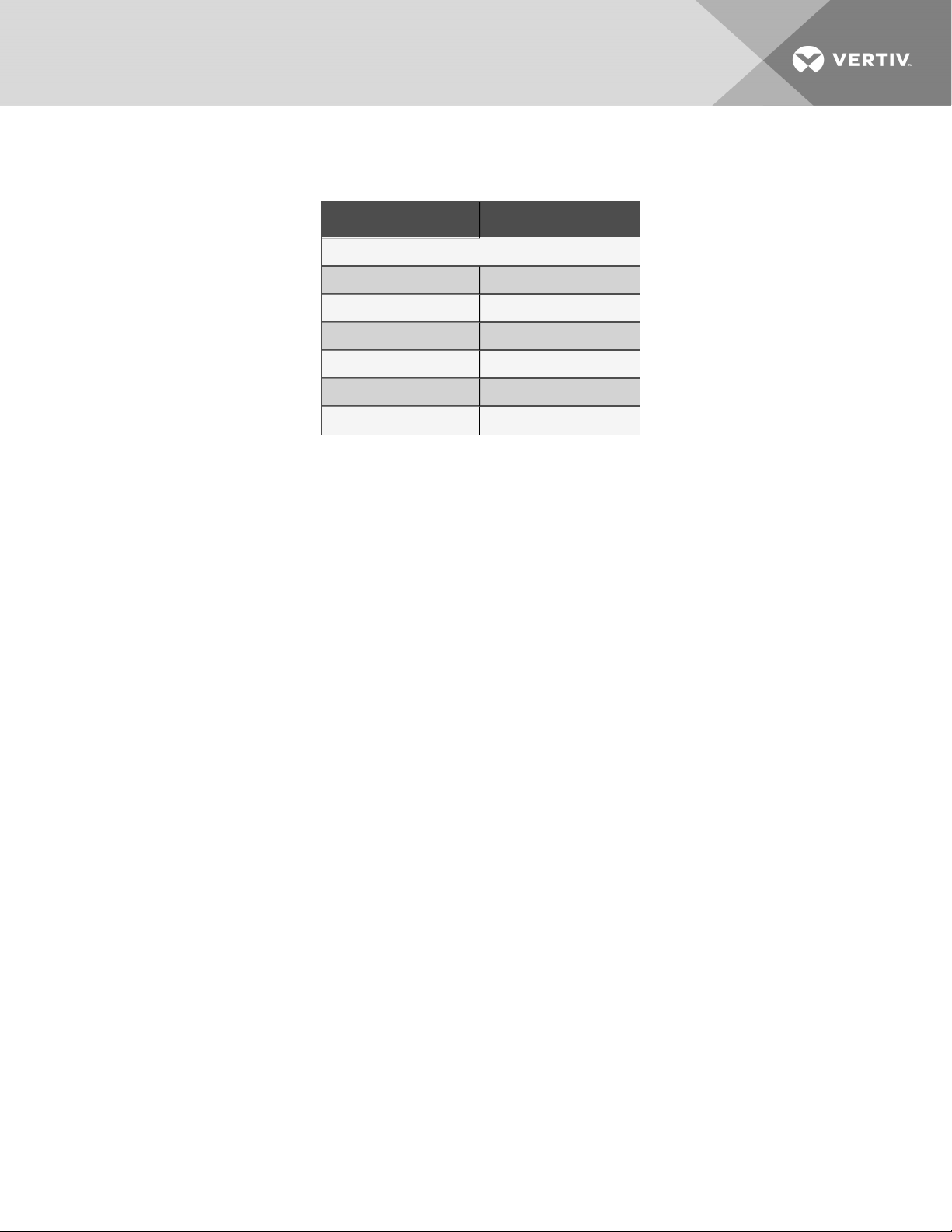
2.2 Nomenclature for Split System Condensing Units
This section describes the model number configuration for Mini-Mate2 splitssystem condensing units.
2.2.1 Indoor Condensing Units for Air Cooled Split Systems
Table 2.4 below describes each digit of the model number.
Table 2.3 Indoor, Air Cooled Condensing Unit Nomenclature Example
1 2 3 4 5 6 7 8 9 10
M C D 3 6 A L A H N
Table 2.4 Nomenclature Digit Definitions for Indoor, Air Cooled Condensing Units
Digit Description
Digits 1 to 2 = the base unit
MC = Mini-Mate2 condensing unit
Digit3 = Disconnect
D = Disconnect switch
Digit4 a nd 5 = Nominal Capacity
24 = 24 kBtuh,60Hz
35 = 35 kBtuh, 50Hz
36 = 36 kBtuh, 60Hz
Digit6 = Cooling type
A = Air Cooled
Digit7 = Head-pressure control
L = Liebert® Lee-Temp™ Receiver
Digit8 = Supply power
A = 460V /3ph / 60Hz(3-toncapacity only)
M = 380/415V / 3ph / 50Hz (3-ton capacity only)
P = 208/230V / 1ph / 60Hz
S = 220V / 1ph /50Hz (3-ton capacity only)
X = 277V / 1ph / 60 Hz
Y = 208/230V / 3ph / 60Hz(3-toncapacity only)
Digit9 = Hot-gas bypass
H = Hot-gas bypass
Digit10 = Refrigerant
N = R-407C field charged
2 Nomenclature
9
Page 16
2.2.2 Outdoor Prop Fan Condensing Units for Air Cooled Split Systems
Table 2.6 below describes each digit of the model number.
Table 2.5 Prop Fan Condensing Unit Nomenclature Example
1 2 3 4 5 6 7 8 9 10 11
P F H 0 3 7 A — P L N
Table 2.6 Nomenclature Digit Definitions for Outdoor, Prop Fan Condensing Units
Digit Description
Digits 1 to 3 = the base unit
PFH = Prop-fan condensing unitwith hot gas bypass
Digit4 = Sound level
0 = Standard
Z = Quiet-Line
Digit5 and 6 = Nominal Capacity
27 = 27 kBtuh, 60Hz
36 = 36 kBtuh, 50Hz
37 = 37 kBtuh, 60Hz
Digit7 = Cooling type
A = Air-cooled
Digit8 = Coiltype
— = Standard coil
C = Coated coil (epoxy with UVtopcoat)
Digit9 = Supply power
A = 460V /3ph / 60Hz(3-toncapacity only)
B = 575V /3ph / 60Hz(3-ton capacity only, Quiet-Line not available)
M = 380/415V / 3ph / 50Hz (3-ton capacity only)
P = 208/230V / 1ph / 60Hz
S = 220V / 1ph /50Hz (3-ton capacity only)
Y = 208/230V / 3ph / 60Hz(3-toncapacity only)
Digit10 = Ambient rating/Control
L = 95°F Ambient, Liebert® Lee-Temp™
H = 105°F Ambient, Liebert®Lee-Temp™
Digit11 = Refrigerant
N = R-407C field charged
10
Vertiv | Li ebert® Mini-Mate2™ Installer/Us er Guide
Page 17
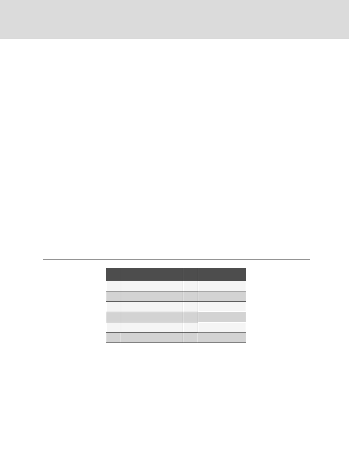
2.2.3 Water/Glycol-cooled Condensing Units
Table 2.8 below describes each digit of the model number.
Table 2.7 Remote, Indoor Water/Glycol Condensing Unit Nomenclature Example
1 2 3 4 5 6 7 8 9 10
M C D 3 8 W 2 A H N
Table 2.8 Nomenclature Digit Definitions for Indoor, Water/Glycol Cooled Condensing Units
Digit Description
Digits 1 to 2 = the base unit
MC = Mini-Mate2 condensing unit
Digit3 = Disconnect
D = Disconnect switch
Digit4 a nd 5 = Nominal Capacity
26 = 26 kBtuh, 2-ton, 60Hz
37 = 37 kBtuh, 3-ton, 50Hz
38 = 38 kBtuh, 3-ton, 60Hz
Digit6 = Cooling type
W = Water/Glycol-cooled
Digit7 = Head-pressure control
2 = 2-way standard-pressure fluid-regulatingvalv e
3 = 3-way standard-pressure fluid-regulating valve
D = 2-way high pressure fluid-regulating valve
T = 3-way high pressure fluid-regulatingvalv e
Digit8 = Supply power
A = 460V /3ph / 60Hz(3-toncapacity only)
M = 380/415V / 3ph / 50Hz (3-ton capacity only)
P = 208/230V / 1ph / 60Hz
S = 220V / 1ph /50Hz (3-ton capacity only)
X = 277V / 1ph / 60 Hz
Y = 208/230V / 3ph / 60Hz(3-toncapacity only)
Digit9 = Hot-gas bypass
H = Hot-gas bypass
Digit10 = Refrigerant
N = R-407C field charged
2 Nomenclature
11
Page 18
2.3 System Configurations
The following figures show the available capacity and cooling options for the Liebert® Mini-Mate2.
Figure 2.1 Air Cooled Units
Item Description
1 Splitsystem (indoor condensingunit)with supply/return air plenum
2 Split-system (indoor condensingunit)with ducted supply/returnair
3 Split-system (outdoor condensing unit) with supply/returnair plenum
4 Split-system (outdoorcondensing unit) with ducted supply/return air
5 Indoorcondensing unit
6 Evaporator
7 Outdoor condensingunit
12
Vertiv | Li ebert® Mini-Mate2™ Installer/Us er Guide
Page 19
Figure 2.2 Water/Glycol Cooled Units
2 Nomenclature
Item Description Item Description
Split-system glycol cooled
1
with supply/return air plenum
Split-system glycol cooled
2
with ducted supply/returnair
Split-system water-cooled
3
with supply/return air plenum
Split-system water-cooled
4
with ducted supply/returnair
6 Expansion tank
7 Pump
8 Water/glycol condensing unit
9 Evaporator
5 Drycooler 10 Cooling tower
13
Page 20
Figure 2.3 Chilled Water Units
Item Description
1 Chilled-water cooled with supply/return air plenum
2 Chilled-water cooled withducted supply/return air
14
Vertiv | Li ebert® Mini-Mate2™ Installer/Us er Guide
Page 21
3 SITE PREPARATION AND EQUIPMENT HANDLING
NOTE: Before installing unit, determine whether any building alterations are required to run piping, wiring and duct
work. Follow all unit dimensional drawings and refer to the submittal engineering dimensional drawings of individual
units for proper clearances.
3.1 Planning Dimensions
The unit dimensions are described in the submittal documents included in the Submittal Drawings.
The following table lists the relevant documents by number and title.
Table 3.1 Dimension Planning Drawings
Docu ment Number Title
Split System Evaporators/Chilled Water Units
DPN000193 Evaporator/Chilled Water and Option Dimensions, All Direct Drive Blower Units
DPN000194 Evaporator/Chilled Water Dimensions, All Belt Drive Blower Units
IndoorCondensingUnits
DPN004420 Cabinet Dimensions, Air Cooled Units
DPN004421 Cabinet Dimensions, Water/Glycol Cooled Units
3.2 Room Preparation
The room should be well insulated and must have a sealed vapor barrier. The vapor barrier in the ceiling and walls can be a
polyethylene film. Paint on concrete walls and floors should be vapor resistant.
NOTE: The vapor barrier is the single most important requirement for maintaining environmental control in the
conditioned area.
Outside or fresh air should be kept to a minimum when tight temperature and humidity control is required. Outside air adds
to the site’s cooling, heating, dehumidifying and humidifying loads. Doors should be properly sealed to minimize leaks and
should not contain ventilation grilles.
NOTE: Temperature and humidity sensors are located in the wall box. Proper and efficient cooling requires placing
the wall box where discharge air does not directly blow on the sensors.
3.2.1 Duct Work Considerations for the Indoor Air Cooled Condensing Unit
Observe the following when planning the installation of the indoor air cooled condensing unit:
Ensure a satisfactory source of clean air for the condensing unit supply and a means to discharge the hot air without
allowing the supply and discharge air to mix. Consider duct work to outdoor air. Duct work for outdoor air to and from the
condensing unit is optional.
The total external static pressure for the inlet and outlet ducts, including grille, must not exceed 0.5in. of water. Hood intake
and duct work cross-sectional area dimensions should be equal to or greater than the area of the condensing unit intake
flange.
For all duct work installation, see Guidelines for Ducted Systems on page25
3 S ite Preparation and Equipment Handling
15
Page 22
3.3 Application Limits
Table 3.2 Application Limits for Evaporator and Chilled-water Units
Input voltage Range o f Return Air Co nditions to the U nit*
Minimum Maximum Dry Bu lb Temperature Relative Humidity
–5% +10% 65 to 85°F (18 to 29°C) 20 to 80%
*The unit will operate at these conditions, but it willnot control to these condition extremes.
Table 3.3 Application Limits for Indoor and Outdoor Air-cooled Condensing Unit
Input Voltage
Condensing Unit Type
Minimum Maximum Minimum Maximum
Entering Dry Bulb Air Temperature
115°F (48°C)standard-
–5% +10%
Outdoor Prop-fan
condensing unit
–30°F (–34°C)
ambient unit*
125°F (52°C)high-ambient
unit*
–5% +10%
Indoorair cooled condensing
unit
–30°F (–34°C) 115°F (48°C)*
*Unit capacity ratings are stated for 95°F (35°C) for standard units and 1 05°F (41°C) for PFH high-ambient units. Exceeding these rating points by 20°F
(11°C) will result in lower cooling ca pacities, but will notdamage the equipment.
Table 3.4 Application Limits for Indoor Water/Glycol Cooled Condensing Unit
Input voltage E ntering fluid temperature
Minimum Maximum Minimum* Maximum
–5% +10% 65°F (18°C)* 115°F (46°C)
*Operation below 65°F (18°C) may result in fluid noise and reduced valve life.
16
Vertiv | Li ebert® Mini-Mate2™ Installer/Us er Guide
Page 23
3.4 Indoor Unit Weights
Table 3.5 Indoor Unit Weights
Model # Weight, lb (kg)
Cooling Units *
MMD24E 225 (102)
MMD35E 225 (102)
MMD36E 225 (102)
MMD39C 230 (104)
MMD40C 230 (104)
High static Blower Module 85 (39)
3 S ite Preparation and Equipment Handling
17
Page 24
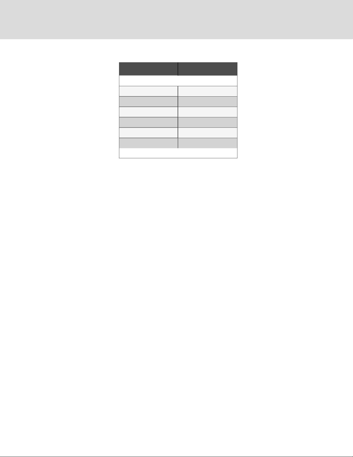
Table 3.5 Indoor Unit Weights (continued)
Model # Weight, lb (kg)
IndoorCondensingUnits
MCD24A 230 (104)
MCD35A 240 (109)
MCD36A 240 (109)
MCD26W 1 75 (79)
MCD37W 220 (100 )
MCD38W 220 (100)
*Add20 lb. (9kg) to units with free cooling or hot water reheat coils.
3.5 Location Considerations
When determining installation locations, consider that these units contain water and that water leaks can cause damage to
sensitive equipment and furniture below.
NOTICE
Risk of leaking water/glycol. Can cause equipment and building damage.
Improper installation, application, and service practices can result in water leakage from the unit. Do not mount
this unit over equipment and furniture that can be damaged by leaking water. Install a water-tight drain pan
with a drain connection under the cooling unit and the ceiling mounted water/glycol condensing unit. Route the
drain line to a frequently-used maintenance sink so that running water can be observed and reported in a
timely manner. Post a sign to alert people to report water flowing from the secondary drain pan. We
recommend installing monitored leak detection equipment for the unit and supply lines and in the secondary
drain pan. Check drain lines periodically for leaks, sediment buildup, obstructions, kinks and/or damage and
verify that they are free running.
3.5.1 Location Considerations for Evaporator, Indoor Condensing,andChilled WaterUnits
The evaporator or chilled water unit is usually mounted above the suspended ceiling and must be securely mounted to the
roof structure. For ducted systems, the evaporator may be located in a different room from the heat-producing equipment.
For a split system with an indoor condensing unit, the condensing unit may be:
• Installed above the suspended ceiling near the evaporator or closely-coupled with the evaporator.
• In any remote indoor area, subject to the requirements detailed in Piping when Condensing Unit is Above or
Below Evaporator on page35.
Refer to Refrigerant Line Sizes and Equivalent Lengths on page36 for maximum refrigerant line lengths.
The ceiling and ceiling supports of existing buildings may require reinforcement. Be sure to follow all applicable national
and local codes.
Install the ceiling-mounting over an unobstructed floor space if possible. This will allow easy access for routine maintenance
or service. Do not attach additional devices (such as smoke detectors, etc.) to the housing, as they could interfere with the
maintenance or service.
18
Vertiv | Li ebert® Mini-Mate2™ Installer/Us er Guide
Page 25

NOTE: Temperature and humidity sensors are in the wall box. Install the wall box where discharge air DOES NOT
blow directly on the sensors.
Do not install units in areas where normal unit operating sound may disturb the working environment.
When installing an air cooled or water/glycol cooled unit inside a space, ensure that national and local codes are met for
refrigerant concentration limits that might vary with building type and use.
3.5.2 Location Considerations for an Outdoor Condensing Unit
For a split system with an air cooled, outdoor condensing unit, the condensing unit may be mounted on the roof or remotely
in any outdoor area.
Observe the following when planning the installation of the outdoor unit:
• To ensure a satisfactory air supply, locate air cooled condensing units in an environment with clear air, away
from loose dirt and foreign matter that may clog the coil.
• Condensing units must not be located in the vicinity of steam, hot air or fume exhausts or closer than 18 inches
from a wall, obstruction or adjacent unit.
• Avoid areas where heavy snow will accumulate at air inlet and discharge locations.
• The condensing unit should be located for maximum security and maintenance accessibility. Avoid groundlevel sites with public access. Install a solid base, capable of supporting the weight of the condensing unit.
• The base should be at least 2in. (51mm) higher than the surrounding grade and 2 in. (51mm) larger than the
dimensions of the condensing-unit base. For snowy areas, a base of sufficient height to clear snow accumulation
must be installed.
• Securely attach the unit to the base using the holes provided in the unit mounting rails to prevent unit
movement that might stress refrigerant piping and electrical wiring.
Before beginning, refer to Piping and Refrigerant Requirements on page27 for unit placement, piping guidelines, and
refrigerant-charge requirements for your system.
The condensing unit must be located within the maximum distance from evaporator guidelines listed in 5.2.1 on page35.
3.6 Equipment Inspection and Handling
CAUTION: Risk of contact with sharp edges, splinters, and exposed fasteners. Can cause injury. Only
properly trained and qualified personnel wearing appropriate, OSHA-approved PPE should attempt to move,
lift, remove packaging from or prepare the unit for installation.
Do not uncrate the equipment until it is close to its final location. All required assemblies are banded and shipped in
corrugated containers. If any damage is discovered when the unit is uncrated, report it to the shipper immediately. If any
concealed damage is later discovered, report it to the shipper and to your Vertiv representative.
3.7 Packaging Material
All material used to package this unit is recyclable. Save it for future use or dispose of the material appropriately.
3 S ite Preparation and Equipment Handling
19
Page 26

This page intentionally left blank
20
Vertiv | Li ebert® Mini-Mate2™ Installer/Us er Guide
Page 27

4 INSTALLATION
Refer to the appropriate installation procedures depending the configuration and options of your Liebert® Mini-Mate2
Thermal Management System.
4.1 Installing Ceiling Mounted EvaporatorsandCondensing Units
WARNING! Risk of ceiling collapse and heavy unit falling. Can cause building and equipment damage, serious
injury or death. Verify that the supporting roof structure is capable of supporting the weight of the unit(s)
and the accessories. See Indoor Unit Weights on page17, for the unit weights. Securely anchor the top ends
of the suspension rods and verify that all nuts are tight.
NOTICE
Risk of leaking water/glycol. Can cause equipment and building damage.
Improper installation, application, and service practices can result in water leakage from the unit. Do not mount
this unit over equipment and furniture that can be damaged by leaking water. Install a water-tight drain pan
with a drain connection under the cooling unit and the ceiling mounted water/glycol condensing unit. Route the
drain line to a frequently-used maintenance sink so that running water can be observed and reported in a
timely manner. Post a sign to alert people to report water flowing from the secondary drain pan. We
recommend installing monitored leak detection equipment for the unit and supply lines and in the secondary
drain pan. Check drain lines periodically for leaks, sediment buildup, obstructions, kinks and/or damage and
verify that they are free running.
4.1.1 Installing Suspension Rods andMounting Ceiling Units
Refer to the Location Considerations on page18 before beginning installation. These instructions apply to evaporators,
indoor air cooled condensing units, and indoor water/glycol cooled condensing units.
NOTE: Follow all national and local building, electrical and plumbing codes.
• The ceiling and ceiling supports of existing buildings may require reinforcements.
• Four 3/8-in. 16 TPI threaded suspension rods are required and field supplied.
• For units with a high-static blower module, two additional suspension rods are required. Hang the evaporator
before raising/attaching the high-static blower module.
• The factory-supplied 3/8-in. 16 TPI hardware kit includes the remaining installation hardware.
• Recommended clearance between ceiling grids and building structural members is the unit’s height plus 3in.
(76mm).
To install the suspension rods:
1. Install the four field supplied 3/8-in.-16 TPI threaded rods by suspending them from suitable building structural
members so that they will align with the four mounting locations on the unit base.
2. Securely anchor the top ends of the suspension rods with field supplied nuts.
3. Make sure all nuts are tight and locked.
4 Installation
21
Page 28
To lift and install the unit on the rods:
1. Using a suitable lifting device that is rated for the weight of the unit (see Indoor Unit Weights on page17), raise
the unit and pass the threaded rods through the four mounting locations in the unit base.
2. Attach the threaded rods to the flanges using the plain nuts to hold the unit in place as shown in Figure 4.1
below.
3. Slowly lower the lifting device, making sure that the rods securely hold the weight of the unit.
4. Adjust the plain nuts to distribute the weight of the unit evenly by the rods, making sure that the unit does not
rest on the ceiling grid and that the unit is level.
NOTE: Evaporator units must be level to properly drain condensate. This does not apply to condensing units.
5. Use the Nylock nuts to "jam" the plain nuts in place as shown in Figure 4.1 below.
Figure 4.1 Installing Threaded Rods and Hardware of Ceiling Mounted Units
Item Description Item Description
1 3/8-in. threaded rod, field supplied 7 3/8-in. fender washer
2 3/8-in. hex nut 8 3/8-in. hex nut
3 3/8-in. washer 9 3/8-in. Nylock locking nut
4 Sleeve 10 Unit base pan (reference)
5 Bracket on unit
6 Isolator
22
Vertiv | Li ebert® Mini-Mate2™ Installer/Us er Guide
Page 29
4.1.2 Close Coupled Installations forIndoorCondensingUnits
You can mount the evaporator and indoor condensing units directly next to each other, close coupled.
Close coupled installations may take advantage of a single point power kit to allow one power feed to provide input for both
evaporator and condensing units.
To Install Close Coupled Indoor Units
1. If you are using a single point power kit:
• Install the single point power box into the evaporator before assembling the condensing unit to the
evaporator and before raising the unit to the ceiling.
• Route power wire flex conduit into condensing unit when raising units to ceiling.
• Refer to the instructions supplied with kit for details
2. Raise the units to the ceiling before connecting them. See Installing Suspension Rods andMounting Ceiling
Units on page21.
3. Align the four bolt holes in the condensing unit with cage nuts provided on the evaporator.
4. Insert rubber spacers and secure with hardware (field provided).
5. Align the refrigerant connections as shown in Figure 4.2 below.
6. Braze the refrigerant connections together as detailed in Refrigerant Piping on page34.
Figure 4.2 Evaporator/Condensing Unit Close Coupling Connections
4 Installation
Item Description
1 Close-coupled connections
2 Spacer between evaporator and condensing unit in close coupled installations
23
Page 30

4.2 Installing Air Distribution Components for Evaporators
Your indoor units may include a filter box, ducting, plenums, and grilles. Refer to the appropriate installation procedures for
each.
4.2.1 Installing a Plenum
The 2- and 3-ton, non-ducted evaporators can use the optional ceiling mounted plenum to provide four-way air distribution.
The plenum fastens to the bottom of the evaporator. The plenum includes a 16-in.x25-in.x4-in.
(406-mmx635-mmx102-mm) MERV8 filter (per ASHRAE52.2-2007).
To Install the Plenum
1. Make sure that the evaporator is mounted above the bottom of the T-bar supports with at least 30in.(762mm)
clearance from the return air end to the wall (to provide clearance for replacing filter).
2. Check the contents of the plenum kit.
3. Follow the installation instructions included with the plenum kit.
NOTE: Do not operate the unit without filters installed in the return air system.
4.2.2 Installing a Filter Box
The optional filter box attaches directly to the return air opening of the evaporator. The filter box includes one MERV 8 filter
(per ASHRAE 52.2-2007), 20in. x 20 in. x 4 in. (508mmx508mmx102mm).
NOTE: Do not operate the unit without filters installed in return air system.
24
Vertiv | Li ebert® Mini-Mate2™ Installer/Us er Guide
Page 31

4.2.3 Guidelines for Ducted Systems
Observe the following for all duct work:
• Duct work should be fabricated and installed in accordance with local and national codes
• Use flexible duct work or nonflammable cloth collars to attach duct work to the unit and to control vibration
transmission to the building.
• Attach the duct work to the unit using the flanges provided.
• Locate the unit and duct work so that the discharge air does not short-circuit to the return air inlet.
• Duct work that runs through a conditioned space or is exposed to areas where condensation may occur must
be insulated. Insulation of duct work is vital to prevent condensation during the cooling cycle.
• The use of a vapor barrier is required to prevent absorption of moisture from the surrounding air into the
insulation.
• If the return air duct is short or if noise is likely to be a problem, sound-absorbing insulation should be used
inside the duct.
• Duct work should be suspended using flexible hangers. Duct work should not be fastened directly to the
building structure.
• For multiple unit installations, space the units so that the hot condensing unit exhaust air is not directed toward
the air inlet of an adjacent unit.
Consider the following in specific applications of duct work to evaporator or chilled water units:
• The duct work should be designed based on the unit size and high-speed air flow shown in Table 4.1 below.
Table 4.1 Duct Work for Cooling Unit Air Flow at0.3iwg(75PA) ESP
Fan Speed 2 Ton , CFM (CMH) 3 Ton , CFM (CMH)
High 885 (1504) 1250 (212 4)
Low (direct drive blowersonly) 800 (1359) 1000 (1699)
• The evaporator has a maximum allowable external static pressure of 03in. wg (75Pa) with the internal, direct
drive blower option..
4 Installation
25
Page 32

Consider the following in specific applications of duct work to condensing units:
• In applications where the ceiling plenum is used as the heat rejection domain, the discharge air must be
directed away from the condensing unit air inlet and a screen must be added to the end of the discharge duct
to protect service personnel. Locate the air discharge a minimum of 4 ft from an adjacent wall. Failure to do so
may result in reduced air flow and poor system performance.
• If the condensing unit draws air from the outside of the building, rain hoods must be installed. Hood intake and
duct work cross-sectional area dimensions should be equal to or greater than the area of the condensing unit
intake flange. In addition, install a triple-layer bird screen over rain hood openings to eliminate the possibility of
insects, birds, water, or debris entering the unit. Avoid directing the hot exhaust air toward adjacent doors or
windows.
Table 4.2 Indoor Condensing Unit Airflow, CFM at0.5iwg(124PA) esp
2 Ton 3 Ton
1000 1 430
26
Vertiv | Li ebert® Mini-Mate2™ Installer/Us er Guide
Page 33

5 PIPING AND REFRIGERANT REQUIREMENTS
All field supplied refrigeration piping to the unit must be sweat copper. Use prevailing good piping practices for all
connections which include brazing copper pipes using a brazing alloy of minimum temperature of 1350 °F (732 °C) and
adhering to all local codes. All other fluid connections to units, with the exception of the condensate drain, are sweat copper.
Factory installed piping brackets must not be removed. Field installed piping must be installed in accordance with local
codes and must be properly assembled, supported, isolated and insulated. Avoid piping runs through noise sensitive areas,
such as office walls and conference rooms.
The following pipe connections are required:
• A drain line from the evaporator coil drain pan.
• A drain line from the secondary drain pan (if applicable).
• A water supply line to the optional humidifier (if applicable).
• On split systems systems: refrigerant piping connections between the evaporator unit and the condensing unit.
• On chilled water systems: connections to the building chilled water source. See Chilled Water Loop Piping on
page31, for additional requirements.
• On water/glycol systems: connections to a water or glycol loop. See Water/Glycol Loop Piping on page32, for
additional requirements.
Refer to specific text and detailed diagrams in this manual for other unit-specific piping requirements.
The pipe connection locations, piping general arrangement and schematics are described in the submittal documents
included in the Submittal Drawings.
The following tables list the relevant documents by number and title.
Table 5.1 Piping General Arrangement Drawings
Docu ment Number Title
DPN004409 PipingSchematic, Water/Glycol Cooled
DPN004410 Piping Schema tic, Air Cooled and Chilled Water
DPN000197 Piping Schematic, Free Coolingand Hot Water Reheat Options
Table 5.2 Piping Connection Drawings
Docu ment Number Title
Evaporator and Chilled-water Units
DPN004303 Piping Connections
Split-system Indoor Condensing Units
DPN004420 Piping Connections, Air Cooled condensingunit
DPN004421 P iping Connections, Water/Glycol-cooled condensing unit
5 Pi pin g and Refrigerant Requirements
27
Page 34

5.1 Fluid Piping Required
5.1.1 Drain Line Installation Requirements
NOTICE
Risk of water backing up in the drain line. Leaking and overflowing water can cause equipment and building
damage.
Do not install an external trap in the drain line. This line already has a factory installed trap inside the cabinet.
Installation of a second trap will prevent drain water flow and will cause the water to overflow the drain pan.
This line may contain boiling water. Use copper or other material that is rated for handling boiling water for the
drain line. Sagging condensate drain lines may inadvertently create an external trap.
A 3/4 in. (19.1mm) NPT-female connection is provided for the evaporator-unit condensate drain. This connection also drains
the humidifier if applicable. The evaporator drain pan includes a float switch to prevent unit operation if the drain becomes
blocked.
28
Vertiv | Li ebert® Mini-Mate2™ Installer/Us er Guide
Page 35

Observe the following requirements and refer to Figure 5.1 below, when installing and routing the drain line:
• The drain line must be sized for 2gpm (7.6 l/m) flow.
• The drain line must be located so it will not be exposed to freezing temperatures.
• The drain should be the full size of the drain connection.
• The drain line must slope continuously away from the unit.
• Do not externally trap the drain line.
• The drain line must be rigid enough that it does not sag between supports, which unintentionally creates traps.
• Use copper or other material suitable for draining water that can reach temperatures up to 212°F (100°C).
• When the evaporator is installed below the level of the gravity fed drain line, the optional condensate pump kit
is required. See Condensate Drain Pump Kit on the next page.
NOTE: Remove the shipping band from the float switch in the evaporator pan before operating the unit.
Figure 5.1 Correct and Incorrect Gravity Drains
Table 5.3 Gravity Fed Drain Line Figure Descriptions
Item Description
1 Correct drain installation.
2 Incorrect. Do not trap ex ternally.
3 Incorrect. Sagging between supports and bowed line causes unintentional external traps.
4 Continuous downwardslope away from the unit.
5 Unit
6 External trap
7 Unintentional traps from bowing of line. Lines must be rigid enough not to bow or sag between supports, creating a trap.
5 Pi pin g and Refrigerant Requirements
29
Page 36

5.1.2 Condensate Drain Pump Kit
WARNING! Risk of electric shock. Can cause equipment damage, injury or death. Open all local and remote
electric power supply disconnect switches and verify with a voltmeter that power is off before working within
any electric connection enclosures. Service and maintenance work must be performed only by properly
trained and qualified personnel and in accordance with applicable regulations and manufacturers’
specifications. Opening or removing the covers to any equipment may expose personnel to lethal voltages
within the unit even when it is apparently not operating and the input wiring is disconnected from the
electrical source.
The optional condensate pump kit is required when the evaporator is installed below the level of the gravity fed drain line.
The condensate pump is field installed alongside the evaporator unit.
Table 5.4 Condensate Drain Pump Drawings
Docu ment Number Title
DPN004445 Field Installed Pump Connection
To Install the Condensate Drain Pump
1. Refer to the instructions and drawings supplied with the pump. The preferred mounting method is to attach the
pump to the unit with the mounting bracket kit instead of mounting the pump to duct work.
2. Disconnect all power to the unit.
3. Remove the access panels.
NOTE: Remove the shipping band from the float switch in the evaporator pan.
4. Use mounting brackets if the pump is not attached to duct work.
5. The pump inlet must be at least 1/2in. (13mm) below the evaporator drain. Mount the pump to the unit exterior
as shown the piping-connection diagram for your unit, see Table 5.4 above.
6. Connect 3/4 in. flexible rubber tubing with a hose clamp (both supplied with pump kit) to the 3/4in. hose barb
fitting on the pump.
7. Connect the evaporator drain to 3/4 in. NPT female hose assembly on the pump inlet using 3/4 in. hard pipe.
Do not install a trap in the line. Provide at least 1 in. (25mm) clearance between the access panel and the drain
line. Support the piping as required.
8. Connect a drain line to the pump discharge 3/8 in. O.D. Cu (compression fitting provided).
9. Connect electric leads L1 and L2 to the unit line-voltage terminal block. Connect the ground lead to the lug
near the terminal block.
10. Connect wires from the auxiliary pump contacts to unit terminals TB1-8 and TB1-9 to enable unit shut down
upon high-water condition in the pump.
11. Reinstall the access panels.
30
Vertiv | Li ebert® Mini-Mate2™ Installer/Us er Guide
Page 37

12. Reconnect power to the unit.
13. Run the unit to make sure the pump works properly. Operate the pump and check the drain line and discharge
line for leaks. Correct as needed.
NOTE: 3/4-in. flexible rubber tubing assembly (supplied with pump kit) must be installed on pump end of rigid piping
(field provided and supported as required).
5.1.3 Water Supply Line to the Humidifier
Units supplied with the optional humidifier package have a 1/4-in. (6.2-mm) OD copper compression fitting with ferrule at
the water supply connection.
• The supply pressure range is 10psig to 150psig (69to1034kPag).
• The required flow rate is 1 gpm (3.8 lpm).
• Install a shutoff valve in the supply line to isolate the humidifier for maintenance.
NOTE: Do not route humidifier water supply line in front of the filter-box access panel.
To Install the Water Supply
1. Cut the tube square and remove any burrs.
2. Slide nut, then the sleeve on tube. The threaded end of the nut faces the end of the tube.
3. Insert the tube into the fitting, seating it against the stop shoulder and tighten the nut hand-tight to the body.
4. Use a wrench to tighten the nut 1-1/4 to 2-1/4 turns.
NOTICE
Risk of improper tightening of the piping fittings. Can damage fittings and cause leaks.
Use caution not to over-tighten or under-tighten the piping fittings.
5.1.4 Chilled Water Loop Piping
NOTICE
Risk of piping system corrosion and freezing fluids. Can cause leaks resulting in equipment and very expensive
building damage. Cooling coils and piping systems are at high risk of freezing and premature corrosion. Fluids
in these systems must contain the proper antifreeze and inhibitors to prevent freezing and premature coil and
piping corrosion. The water or water/glycol solution must be analyzed by a competent local water treatment
specialist before start up to establish the inhibitor and antifreeze solution requirement and at regularly
scheduled intervals throughout the life of the system to determine the pattern of inhibitor depletion.
The complexity of water/glycol solution condition problems and the variations of required treatment programs
make it extremely important to obtain the advice of a competent and experienced water treatment specialist
and follow a regularly scheduled coolant fluid system maintenance program.
Water chemistry varies greatly by location, as do the required additives, called inhibitors, that reduce the
corrosive effect of the fluids on the piping systems and components. The chemistry of the water used must be
considered, because water from some sources may contain corrosive elements that reduce the effectiveness of
the inhibited formulation. Sediment deposits prevent the formation of a protective oxide layer on the inside of
the coolant system components and piping. The water/coolant fluid must be treated and circulating through
the system continuously to prevent the buildup of sediment deposits and or growth of sulfate reducing
bacteria.
5 Pi pin g and Refrigerant Requirements
31
Page 38

Proper inhibitor maintenance must be performed in order to prevent corrosion of the system. Consult glycol
manufacturer for testing and maintenance of inhibitors.
Commercial ethylene glycol, when pure, is generally less corrosive to the common metals of construction than
water itself. It will, however, assume the corrosivity of the water from which it is prepared and may become
increasingly corrosive with use if not properly inhibited.
We recommend installing a monitored fluid-detection system that is wired to activate the automatic-closure of
field installed coolant fluid supply and return shut-off valves to reduce the amount of coolant fluid leakage and
consequential equipment and building damage. The shut-off valves must be sized to close-off against the
maximum coolant fluid system pressure in case of a catastrophic fluid leak.
NOTICE
Risk of no flow condition. Can cause equipment damage.
Do not leave the water/coolant fluid-supply circuit in a no flow condition. Idle fluid allows the collection of
sediment that prevents the formation of a protective oxide layer on the inside of tubes. Keep unit switched On
and water/coolant fluid supply circuit system operating continuously.
See Table 5.5 below, for the chilled water loop requirements.
Install manual service shutoff valves at the supply and return lines of each unit. These shutoff valves are used for routine
service and for emergency isolation of the unit.
Refer to the appropriate piping general arrangement schematics for your system for the recommended, field installed
hardware such as shut-off valves and hose bibs. See Table 5.1 on page27.
NOTE: Chilled water supply and return lines must be insulated to prevent condensation of the lines.
Table 5.5 Requirements for Chilled Water Loop nstallation
Minimum Recommended
water temperature, °F(°C)
42 (5.5) 300 (2068) 7/8 O.D. Cu
Standard-pressure valve
design pressure, Psig(Kpag)
Supp ly/Return
Connection Sizes,
in.
5.1.5 Water/Glycol Loop Piping
NOTICE
Risk of frozen pipes and corrosion from improper coolant mixture. Can cause water leaks resulting in
equipment and building damage.
When piping or the cooling unit may be exposed to freezing temperatures, charge the system with the proper
percentage of glycol and water for the coldest design ambient temperature. Automotive antifreeze is
unacceptable and must NOT be used in any glycol fluid system. Use only HVAC glycol solution that meets the
requirements of recommended industry practices.
Do not use galvanized pipe.
Install manual service shut-off valves at the supply and return line to each unit. This permits routine service and emergency
isolation of the unit. Refer to the appropriate submittal drawing for the piping-connection sizes of your unit, see Table 5.2
on page27.
Refer to the appropriate piping general arrangement schematics for your system for the recommended, field installed
hardware such as shut-off valves. See Table 5.1 on page27.
32
Vertiv | Li ebert® Mini-Mate2™ Installer/Us er Guide
Page 39

When the fluid quality is poor, we recommend installing a 16-20# mesh Y-strainer filter in the supply line to extend the
service life of the coaxial condensers. These filters must be easily replaced or cleaned.
The standard maximum fluid pressure is 150 psig (1034 kPa) and 350 psig (2413 kPa) for high pressure systems. For
applications above this pressure, contact a Vertiv representative.
The water/glycol cooled system will operate in conjunction with a cooling tower, city water or drycooler.
NOTE: HVAC grade ethylene or propylene glycol should be used on glycol systems. Automotive antifreeze must not
be used.
Water/Glycol Coolant Regulating Valve
Water/glycol cooled units include a coolant flow regulating valve that is factory-adjusted and should not need field
adjustment.
Standard pressure and high pressure valves are adjusted differently. Contact Vertiv technical support before making any
adjustments.
5.1.6 Free Cooling Coil Piping
An optional, free cooling coil outlet can be field-piped to the condensing-unit inlet on water-cooled systems if a 3-way
regulating valve is installed inside the water/glycol condensing unit.
Refer to the appropriate piping general arrangement schematics for your system for the details of a free cooling coil
installation. See Table 5.1 on page27.
NOTE: If the free cooling coil is piped to an open water tower, a CU/NI (copper/nickel) type coil must be ordered to
prevent corrosion of the copper tubes, or a heat exchanger must separate the tower water from the free cooling loop.
5.1.7 Hot Water Reheat Coil Piping
On chilled water systems, building hot water can be piped to a factory installed hot water reheat coil, located downstream
of the cooling coil. A factory installed solenoid valve opens upon a call for reheat.
Refer to the appropriate piping general arrangement schematics for your system for the details of a hot water reheat coil
installation. See Piping General Arrangement Drawings on page27.
5 Pi pin g and Refrigerant Requirements
33
Page 40

5.2 Refrigerant Piping
WARNING! Risk of over pressurization of the refrigeration system. Can cause piping rupture, explosive
discharge of high pressure refrigerant, loss of refrigerant, environmental pollution, equipment damage,
injury, or death. This unit contains fluids and gases under high pressure. Use extreme caution when
charging the refrigerant system. Do not pressurize the system higher than the design pressure marked on
the unit's nameplate. Relieve pressure before cutting into or making connections/disconnections to the
piping system. Local building or plumbing codes may require installing a pressure-relief device in the
system.
Consult local building and plumbing codes for installation requirements of additional pressure-relief devices
when isolation valves are field installed. Do not isolate any refrigerant circuits from over pressurization
protection. The PFH condensing units include a factory installed pressure relief valve mounted on top of the
receiver. The valve is rated for a maximum working pressure of 475 psig.
NOTICE
Risk of oil contamination with water. Can cause equipment damage.
Liebert®Mini-Mate2DX systems require the use of POE (polyolester) oil. POE oil absorbs water at a much
faster rate when exposed to air than previously used oils. Because water is the enemy of a reliable refrigeration
system, extreme care must be used when opening systems during installation or service. If water is absorbed
into the POE oil, it will not be easily removed and will not be removed through the normal evacuation process. If
the oil is too wet, it may require an oil change. POE oils also have a property that makes them act as a solvent
in a refrigeration system. Maintaining system cleanliness is extremely important because the oil will tend to
bring any foreign matter back to the compressor.
NOTICE
Risk of improper refrigerant charging. Can cause equipment damage.
Refrigerant charge must be weighed into compressorized systems before they are started.
Split systems require two refrigerant lines between the evaporator and the condensing unit:
• One insulated copper suction line
• One copper liquid line
34
Vertiv | Li ebert® Mini-Mate2™ Installer/Us er Guide
Page 41

Observe the following requirements for all field supplied refrigeration piping:
• All piping must be ACR type copper.
• For all piping connections, use prevailing good piping practices, which includes brazing copper pipes using a
brazing alloy of a minimum temperature of 1350°F(732°C) and adhere to local codes.
• Factory-installed piping brackets must not be removed.
• Piping must be installed in accordance with local codes and must be properly assembled, supported, isolated,
and insulated.
• Use prevailing good refrigeration practices such as piping supports, leak testing, evacuation, dehydration and
charging of the refrigeration circuits.
• Isolate the refrigeration piping from the building with vibration-isolating supports.
• Avoid piping runs through noise-sensitive areas such as office walls and conference rooms.
• When sealing openings in walls and to reduce vibration transmission, use a soft, flexible material to pack
around the tubes to prevent tube damage.
• When installing remote condensing units above the evaporator, the suction gas lines should be trapped at the
evaporator. These traps will retain refrigerant oil in the off cycle. When the unit starts, oil in the traps is carried
up the vertical risers and returns to the compressors.
5.2.1 Piping when Condensing Unit is Above or Below Evaporator
Refer to Table 5.6 below, for the maximum vertical rise/fall between condensing unit and evaporator.
When installing remote condensing units above the evaporator, trap the suction gas line at the evaporator as shown in
Figure 5.2 on the next page. This trap will retain refrigerant oil during the "Off" cycle. When the unit starts, oil in the trap is
carried up the vertical riser and returns to the compressor. For rises over 25ft(7.6m), trap every 20ft(6m) or evenly
divided.
When installing remote condensing units below the evaporator, trap the suction gas line with an inverted trap the height of
the evaporator as shown Figure 5.2 on the next page. This prevents refrigerant migration to the compressor during "Off"
cycles. The maximum recommended vertical-level drop to condensing unit is15ft(4.6m).
Table 5.6 Pipe Length and Condensing Unit Elevation relative to evaporator
Nomin al
SystemSize, ton
2 150 (45) 40 (12) 15 (4.6)
3 150 (45) 50 (15) 15 (4.6)
Maximum recommended total equivalent pipe length is150 ft (46m). Suction and liquid lines may require
additional specialty items when vertical lines exceed 20 ft (6m) and/or condensingunit installation
is m ore than 15 ft (4.6m) below the evaporator. Contact Vertiv Technical Support for assistance.
Maximum Equivalent
PipeLength, ft (m)
Maximum
Condensing Unit Level
Abo veEvaporator, ft(m)
Maximum
Condensing Unit Level
BelowEvaporator, ft(m)
5 Pi pin g and Refrigerant Requirements
35
Page 42

Figure 5.2 Refrigerant piping diagram when condenser is above or below evaporator
NOTE: Any horizontal pipe must be pitched down toward the condensing unit at a minimum rate of 1/2in. (13mm) per
10ft(3m) to assure oil return to compressor.
Item Description
1 Condensing unit above evaporator
2 Condensing unit below evaporator
3 Evaporator
4 Condensing unit
5.2.2 Refrigerant Line Sizes and Equivalent Lengths
The following tables list information required to field-install the refrigerant piping for the system.
The pipe connection sizes for your equipment are included in the appropriate submittal documents included in the
Submittal Drawings.
Table 5.7 Recommended Refrigerant Line Sizes, O.D. cu by Equivalent Length
Equivalent Length,
ft(m)
50 (15) 7/8” 3/8” 7/8” 1 /2”
75 (23) 7/8” 3/8” 7/8” 1 /2”
100 (30) 7/8” 1/2” 1-1/8”
125 (38) 7/8” 1/2” 1-1/8”
150 (45) 7/8” 1/2” 1-1/8”
1. Consult factory for proper line sizingfor runs longer than 150ft (45m).
2. Downsize vertical riser one trade size (1-1/8" to 7/8").
3. Suction-line and liquid line sizing based on < 3 psi pressure drop in each and on suction-line refrigerant velocities >700FPM(3.6m/s),
horizontal and 1000FPM(5.1m/s)vertical.
Source:DPN000 788 Rev. 13
Suction Liquid Suction Liquid
2 Ton 3 Ton
2
2
2
1/2”
1/2”
1/2”
36
Vertiv | Li ebert® Mini-Mate2™ Installer/Us er Guide
Page 43

Table 5.8 Equivalent Lengths for Various Pipe Fittings, ft (m)
Copper Pipe
OD, in.
90 Degree
Elbow Co pper
1/2 0.8 (0.24) 1.3 (0.39) 0.4 (0.12) 2. 5 (0.76) 0.26 (0.0 7) 7.0 (2.1 3) 4.0 (1.21)
5/8 0.9 (0.27) 1.4 (0.42) 0.5 (0.15) 2.5 (0.76) 0.28 (0.08) 9.5 (2.89) 5.0 (1.52)
3/4 1. 0 (0.3) 1. 5 (0.45) 0.6 (0.18) 2.5 (0.76) 0.3 (0.09) 12.0 (3.65) 6.5 (1.98)
7/8 1.45 (0.44) 1. 8 (0.54) 0.8 (0.24) 3.6 (1. 09) 0.36 (0.1) 17.2 (5.24) 9.5 (2. 89)
1-1/8 1.85 (0.56) 2.2 (0.67) 1.0 (0.3) 4.6 (1. 4) 0.48 (0.14) 22.5 (6.85) 12. 0 (3.65)
1-3/8 2.4 (0.73) 2.9 (0.88) 1 .3 (0.39) 6.4 (1.95) 0.65 (0.19) 32.0 (9.75) 16.0 (4.87)
1-5/8 2.9 (0.88) 3.5 (1.06) 1.6 (0.48) 7.2 (2.19) 0.72 (0.21 ) 36.0 (10. 97) 1 9.5 (5.94)
Refrigerant trap = Four times equivalent lengthof pipe per thistable
5.2.3 Refrigerant Charge Requirements
Table 5.9 R-407C Refrigerant Unit Charge
Model #
60 Hz 50Hz
MMD24E/K — 7 (0.198)
MMD36E/K MMD35E/K 7 (0.198)
90 Degree
Elbow Cast
45 D egree
Elbow
Tee
Gate
Valve
Charge R-407C, oz (kg)
Globe
Valve
Angle
Valve
MCD24AL_HN — 134 (3.80)
MCD36AL_HN MCD35AL_HN 213 (6.04)
MCD26W_HN — 41 (1.16)
MCD38W_HN MCD37W_HN 54 (1. 54)
PFH027A-_LN — 134 (3.80)
PFH027A-_HN — 213 (6.04)
PFHZ27A-_LN — 213 (6.04)
PFH037 A-_LN PFH036A-_LN 213 (6.04)
PFH037 A-_HN PFH036A-_HN 426 (12.08)
PFHZ37A-_LN PFHZ36A-_LN 426 (12.08)
1. Use Table 5. 10 on the next page to determine the charge to be added for field-fabricated refrigerant lines.
5 Pi pin g and Refrigerant Requirements
37
Page 44

Table 5.10 Line Charges of R-407C Refrigerant Using Type-L Copper Tube
Line Size, OD, in. Liqu id Line, lb/100ft (kg/30m) Suction Lin e, lb/100ft (kg/30m)
3/8
1/2
5/8
3/4
7/8
1-1/8
1-3/8
Source:DPN003099 Rev. 1
3.6 (1.6) —
6.7 (3.0) 0.2 (0.1 )
10. 8 (4.8) 0. 3 (0.1)
16.1 (7.2) 0.4 (0.2)
22.3 (10.0) 0.5 (0.3)
38.0 (17. 0) 0.9 (0.4)
57.9 (25. 9) 1 .4 (0.7)
38
Vertiv | Li ebert® Mini-Mate2™ Installer/Us er Guide
Page 45

5.2.4 Field Fabricated Refrigeration Piping
Use copper pipe with high-temperature brazed joints for all field-fabricated refrigeration piping. Use a brazing alloy with a
minimum temperature of 1350°F (732°C), such as Sil-Fos. Avoid soft solders such as 50/50 or 95/5.
1. Measure pipe runs and calculate pipe size and equivalent feet of suction and liquid lines per the tables in
Refrigerant Line Sizes and Equivalent Lengths on page36.
2. Determine the type of trap to use on the suction line next to the evaporator based on the position of the
condensing unit per Piping when Condensing Unit is Above or Below Evaporator on page35.
3. Determine the number and placement of traps on vertical rises, and install traps on the suction-line piping at
the base of a rise over 5 ft (1.5 m) and every 20 ft (6 m) of vertical rise.
4. The evaporator and condensing units come with an inert gas holding charge. Release pressure before cutting
the spun-closed end of the piping.
NOTE: You can only evacuate the system properly if you open the hot gas bypass and liquid line solenoid valves (if
equipped)inside the condensing unit and you account for all check valves, see Figure 5.3 on the next page. Connect
manifold-gauge hoses to the discharge and suction line Schrader ports, remove the solenoid valve holding coils from
the hot gas bypass and liquid line solenoid valves (if equipped), and apply a solenoid valve service magnet to the
valves to obtain a proper vacuum.
5. Use a flow of dry nitrogen through the piping during brazing to prevent formation of copper oxide scale inside
the piping. A pure dry nitrogen flow of 1to3ft3/min (0.5to1.5 l/s) inside the pipe during brazing is sufficient to
displace the air. Control the flow using a suitable metering device.
NOTE: Copper oxide forms when copper is heated in the presence of air. POE oil will dissolve these oxides from inside
the copper pipes and deposit them throughout the system, clogging filter driers and affecting other system
components.
5.2.5 Evacuation and Leak Testing Air Cooled Systems
For proper leak check and evacuation, you must open all system valves and account for all check valves, see Figure 5.3 on
the next page.
5 Pi pin g and Refrigerant Requirements
39
Page 46

Figure 5.3 Valves and Connections
Item Description
1 Apply a ma nifold gauge hose on the suction line Schrader port.
2 Apply a manifold gauge hose on the discharge line Schrader port.
3 Unplug the wires and remove the solenoid-valve holding coils, then a pply solenoid-valve service magnets to the valves.
4 Suction line
5 Liquid injection-valve bulb
Schrader port with v alve core
NOTE: The syst em includes a factory- nst alled Schrader valve with core in the liquid line downstream of the receiver. Proper evacuation of
6
the condenser side of the system can be accomplished only using the downstream Schrader valve. See the appropriate piping schematic
for your system in Submittal Drawings.
7 Scroll compressor
8 High-pressure switch
9 Condenser coil
10 Hot gas bypass solenoid valve
11 Hot gas bypass control valve
40
Vertiv | Li ebert® Mini-Mate2™ Installer/Us er Guide
Page 47

Item Description
12 Liquidinjection
13 Three way head pressure control va lve
14 Check valve
15 P ressure-balancing valve
16 Sight glass
17 Pressure-relief valve
18 Lee-Temp receiver
19 Receiver-heater pressure-limitingswitch
20 Liquid-line solenoid valve
21 Liquidline
To Evacuate and Leak Test the System
1. Open the liquid line solenoid valve and hot gas bypass solenoid valve by removing the holding coils, and apply
a solenoid valve service magnet to the valves.
2. Connect manifold gauge hoses on the discharge and suction line Schrader ports, open the service valves, and
place a 150Psig(1034kPa)charge of dry nitrogen with a tracer of refrigerant, then check the system for leaks
with a suitable leak detector.
3. After completion of leak testing, release the test pressure, (observe local code) and pull an initial deep vacuum
of 500microns on the system with a suitable pump.
4. After fourhours, check the pressure readings and, if they have not changed, break vacuum with dry nitrogen.
Pull a second and third vacuum to 500 microns or less. Re-check the pressure after two hours. When the three
checks are complete, proceed to Charging Air Cooled Systems below.
5.2.6 Charging Air Cooled Systems
NOTICE
Risk of improper refrigerant charging. Can cause equipment damage.
R-407C is a blended refrigerant and must be introduced and charged from the cylinder only as a liquid.
When adding liquid refrigerant to an operating system, it may be necessary to add the refrigerant through the
valve in the compressor suction line. Care must be exercised to avoid damage to the compressor. We
recommend connecting a sight glass between the charging hose and the compressor suction service valve.
This will permit adjustment of the cylinder hand valve so that liquid can leave the cylinder while allowing vapor
to enter the compressor.
To Calculate the Charge for the System
1. Check the nameplate on the indoor unit for refrigerant type to use.
2. Refer to Table 5.9 on page37, and Table 5.10 on page38, and calculate the amount of charge for the system
including the evaporator, condensing unit, and interconnecting piping.
3. Accurately weigh-in as much of the system charge as possible before re-installing coils on liquid line solenoid
valve and hot gas bypass solenoid valve, and starting the unit.
5 Pi pin g and Refrigerant Requirements
41
Page 48

5.2.7 Field Charge Verification forAir Cooled Systems
An integral sight glass is provided with the receiver to assist in field-charge verification. During charge verification, set the
control temperature down to keep the system running. If the system is equipped with hot gas bypass, de-energize it by
removing power from the hot gas solenoid valve coil. To remove power, disconnect the solenoid leads from the unit
contactor in the electric box, see Figure 5.3 on page40. When charge verification is complete, replace and secure all wire
connections and covers.
During operation at design ambient temperatures, (95 or 105°F; 35 or 41°C) the charge level is above the sight glass in the
receiver. If levels are below the sight glass, an under-charge condition is likely. If levels are above the sight glass and higher
discharge pressures than normal are observed, an overcharge condition may be likely. However, verify that other highdischarge pressure causes such as dirty coil and restricted air flow are not responsible before removing charge.
At temperatures below design ambient temperature, refrigerant backs into the condenser coil and the level in the receiver
drops below the sight glass. If you are trying to verify charge level at lower ambient temperatures, block the condenser coil
to maintain 240psig (1655kPa) discharge pressure to ensure the head pressure control valve is closed. At these conditions
the charge level should be above the sight glass in the receiver.
NOTE: If no level is visible in the sight glass, add charge until the level is in the middle of the sightglass. Check the
discharge pressure during this procedure and adjust coil restrictions to maintain 240psig(1655kPa). Once the
charge is in the middle of the sight glass, add additional system charge per Table 5.11 below. After charging,
unblock the coil and allow the unit to operate normally. After conditions have stabilized, restrict the coil if required to
maintain 240psig(1655kPa) discharge pressure and verify that the charge level is above the sight glass.
Table 5.11 Field Verification Charge Addition
Model Numbers R-407C
60Hz 50Hz oz (kg)
PFH027A-_L — 4 (0.11)
MCD24AL_HN — 4 (0.11)
PFH027A-_H — 18 (0.51 )
PFHZ27A-_L — 18 (0.51)
PFH037 A-_L PFH036A-_L 18 (0.51)
MCD36AL_HN — 18 (0.51)
PFH042A-_L PFH041A-_L 18 (0. 51)
PFH037 A-_H PFH036A-_H 8 (0.23)
PFHZ37A-_L PFHZ36A-_L 8 (0.23)
PFH042A-_H PFH041A-_H 8 (0.23)
PFHZ42A-_L PFHZ 41A-_L 8 (0.23)
See Table 5. 9 on page37, for base charge amount of the condensing unit.
5.2.8 Documenting Refrigerant Charge on AirCooled Units
When the unit is charged, you must record the total system charge value on the condensing unit's serial tag. The total
system charge includes the evaporator, condensing unit, and interconnecting lines.
42
Vertiv | Li ebert® Mini-Mate2™ Installer/Us er Guide
Page 49

5.2.9 Evacuation and Leak-testing Water/Glycol-cooled Systems
For proper leak check and evacuation, you must open all system valves and account for all check valves, see Figure 5.4 on
the next page.
5 Pi pin g and Refrigerant Requirements
43
Page 50

Figure 5.4 Valves and Connections for Remote Water/Glycol Condensing Unit
Item D escription
1 Apply a manifold gauge hose on the suction-line Schrader port.
2 Apply a manifold gauge hose on the discharge-line Schrader port.
3 Unplug the wiresand remove the solenoid-valve holding coil, then apply a solenoid-valve service magnet to the valv e.
4 Suction line
5 Liquidinjection-valve bulb
6 Schrader port with v alve core
7 Scroll compressor
8 High pressure switch
9 Tube in tube condenser
10 Hotgas bypasssolenoid valve
11 Hot gas bypass control valve
12 Liquidinjection
13 Liquidline
14 Water/Glycol return line
44
Vertiv | Li ebert® Mini-Mate2™ Installer/Us er Guide
Page 51

Item D escription
15 Fluid return from unit
16 Shut-off valves (required, field supplied)
17 Hose bibs(required, field supplied)
18 Fluid supply to unit
19 Two way water regulating valve
20 Water/Glycol supply line
21 Three way water regulating valve (optional)
To Evacuate and Leak Test the System
1. Open the hot gas bypass solenoid valve by removing the holding coil, and apply a solenoid-valve service
magnet to the valve.
2. Connect a manifold gauge hose on the discharge- and suction-line Schrader ports, open the service valve, and
place a 150Psig(1034kPa)charge of dry nitrogen with a tracer of refrigerant, then check the system for leaks
with a suitable leak detector.
3. After completion of leak testing, release the test pressure, (observe local code) and pull an initial deep vacuum
of 500microns on the system with a suitable pump.
4. After four hours, check the pressure readings and, if they have not changed, break vacuum with dry nitrogen.
Pull a second and third vacuum to 500 microns or less. Re-check the pressure after twohours. When the three
checks are complete, proceed to Charging Water/Glycol-cooled Systems below.
5.2.10 Charging Water/Glycol-cooled Systems
NOTICE
Risk of improper refrigerant charging. Can cause equipment damage.
R-407C is a blended refrigerant and must be introduced and charged from the cylinder only as a liquid.
When adding liquid refrigerant to an operating system, it may be necessary to add the refrigerant through the
valve in the compressor suction line. Care must be exercised to avoid damage to the compressor. We
recommend connecting a sight glass between the charging hose and the compressor suction service valve.
This will permit adjustment of the cylinder hand valve so that liquid can leave the cylinder while allowing vapor
to enter the compressor.
To calculate the charge for the system:
1. Check the nameplate on the indoor unit for refrigerant type to use.
2. Refer to Table 5.9 on page37, and Table 5.10 on page38, and calculate the amount of charge for the system
including the evaporator, condensing unit, and interconnecting piping.
3. Accurately weigh in as much of the system charge as possible before re-installing the coil on the hot gas
bypass solenoid valve and starting the unit.
5 Pi pin g and Refrigerant Requirements
45
Page 52

5.2.11 Optimizing Refrigerant Charge on Water/Glycol Units
1. Operate the unit at full heat load, normal room conditions and normal water/glycol fluid temperatures for a
minimum of 30 minutes before measuring stable unit superheat and sub-cooling temperatures and adjusting
charge levels.
• Condensing temperatures should be in range of 100 to 130°F (38 to 54°C) depending on fluid type and
fluid temperature.
• Full heat load is required to stabilize the system.
2. Attach pressure and temperature instruments to the liquid line of the condensing unit. Use the factory installed
Schrader valve located in the liquid line of the condenser. Measure the initial sub-cooling.
NOTE: To determine sub-cooling measurement, a liquid line pressure reading (at the factory installed Schrader tap)
must be measured along with the temperature reading on the liquid line. Convert the liquid line pressure reading into
a liquid temperature by utilizing a pressure temperature guide. Subtract the measured temperature from the liquid
saturation temperature. The difference is sub-cooling.
3. Adjust refrigerant charge levels as needed to achieve sub-cooling range of 12 to 14°F (6.7to7.8°C) while
maintaining full load conditions.
5.2.12 Documenting Refrigerant Charge on Water/Glycol Cooled Units
When the unit is charged, you must record the total system charge value on the condensing unit's serial tag. The total
system charge includes the evaporator, condensing unit, and interconnecting lines.
46
Vertiv | Li ebert® Mini-Mate2™ Installer/Us er Guide
Page 53

6 ELECTRICAL CONNECTION REQUIREMENTS
WARNING! Arc flash and electric shock hazard. Open all local and remote electric power-supply disconnect
switches, verify with a voltmeter that power is Off and wear appropriate, OSHA-approved personal protective
equipment (PPE) per NFPA 70E before working within the electric control enclosure. Failure to comply can
cause serious injury or death. Customer must provide earth ground to unit, per NEC, CEC and local codes, as
applicable. Before proceeding with installation, read all instructions, verify that all the parts are included and
check the nameplate to be sure the voltage matches available utility power. The Liebert® controller does not
isolate power from the unit, even in the “Unit Off” mode. Some internal components require and receive
power even during the “Unit Off” mode of the controller. The only way to ensure that there is NO voltage
inside the unit is to install and open a remote disconnect switch. Refer to unit electrical schematic. Follow all
local codes.
WARNING! Risk of improper wire and loose electrical connections. Can cause overheated wire and electrical
connection terminals resulting in smoke, fire, equipment and building damage, injury or death. Use correctly
sized copper wire only and verify that all electrical connections are tight before turning power On. Check all
electrical connections periodically and tighten as necessary.
NOTE: Seal openings around piping and electrical connections to prevent air leakage. Failure to do so could reduce
the unit's cooling performance.
NOTICE
Risk of improper electrical supply connection. Can cause equipment damage.
See transformer label for primary tap connections. Installer will need to change transformer primary taps if
applied unit voltage is other than pre-wired tap voltage.
All power and control wiring and ground connections must be in accordance with the National Electrical Code and local
codes. Refer to the equipment serial-tag data for electrical requirements.
A manual electrical disconnect switch should be installed in accordance with local codes and distribution system. Consult
local codes for external disconnect requirements.
NOTE: Input-power requirements: For 3-phase units, only 3 power wires and an earth ground are required.
Each unit is shipped from the factory with internal wiring completed. Refer to the unit's electrical schematic when making
connections. Electrical connections to be supplied by the users and made at the installation site are:
• Power supply to each ceiling unit.
• Power supply to outdoor condensing unit, if applicable.
• Control wiring (shielded) between the evaporator unit and condensing unit, if applicable.
• Control wiring (shielded) between the control panel (wall box) and the evaporator or chilled water unit's control
board.
The electrical connections are described in the submittal documents included in the Submittal Drawings.
The following table lists the relevant documents by number and title.
6 Electrical Connection Requirements
47
Page 54

Table 6.1 Electrical Field Connection Drawings
Docu ment Number Title
Evaporator and Chilled Water Units
DPN000195 Electrical Connections
DPN000196 Single Point Power Kit for Close-coupled units
DPN004851 Arrangement and Dimensions, UnitMounted IS-UNITY-DP for BMS Communication
DPN004911 Arrangement and Dimensions, WallMounted IS-UNITY-DP for BMS Communication
DPN004854 Electrical Connections, IS-UNITY-DP for BMS Communication
Split System IndoorCondensing Units
DPN000207 Electrical Connections, Air Cooled condensing units
DPN000209 Electrical Connections, Water/Glycol Cooledcondensing units
6.1 Input Power Connection Requirements
WARNING! Risk of loose electrical connections. Can cause overheating of wire, smoke and fire resulting in
building and equipment damage, injury or death. Use copper wiring only. Verify that all connections are
tight.
NOTE: Refer to specifications for full load amp and wire size amp ratings.
Voltage supplied must agree with the voltage specified on the unit serial tag. If a field supplied disconnect switch is
required, it may be bolted to the ceiling unit, but not to any of the removable panels. This would interfere with access to the
unit. Make sure that no refrigerant lines are punctured when mounting the disconnect switch.
Route the electrical-service conduit through the hole provided in the cabinet and terminate it at the electric box. Make
connections at the factory terminal block or disconnect switch, L1, L2, L3. Connect earth ground to lug provided. See
transformer label for primary tap connections. Installer will need to change transformer primary taps if applied unit voltage
is other than pre-wired tap voltage. For 208 VAC applications, the low voltage transformer tap must be changed. Refer to
the electrical schematic.
An optional single point power kit is available for units that are close coupled (See Close Coupled Installations
forIndoorCondensingUnits on page23). This kit should be mounted inside the evaporator before installing the unit in the
ceiling. Specific installation instructions are included with the single point power kit.
48
Vertiv | Li ebert® Mini-Mate2™ Installer/Us er Guide
Page 55

6.2 Control Wiring Connection Requirements
6.2.1 Wall Box Controller Control Connections
A four conductor (thermostat type) field supplied, shielded wire must be connected between the evaporator control board
and the wall box display. Refer to the appropriate submittal drawings for your system for electrical connections. See Table
6.1 on the previous page.
6.2.2 Split-system Condensing-unit Control Connections
A field supplied, shielded, four wire control connection (24 VAC) is required between the evaporator and the condensing
unit.
Control wiring must be installed in accordance with the National Electrical Code (NEC) Class 1 or Class 2 circuit according
to wire-routing conditions chosen and local codes. Water/glycol cooled units require a Class 1 circuit. If installing a Glycol
unit, see Water/Glycol Cooled Unit Control Connections below, for specific requirements.
Control wiring between the evaporator and the condensing unit must be shielded and sized for a voltage drop of less than
onevolt, see Table 6.2 below, for recommended minimumgauge by distance. Connect the shield wire to earth (ground) at
the Liebert® equipment. Avoid running the low voltage connections near high voltage lines or loads such as light ballasts.
NOTE: Do not connect additional electrical devices to the control circuit. The internal control transformer is only sized
for factory-supplied components. Refer to the appropriate submittal drawings for your system for electrical
connections. See Table 6.1 on the previous page.
Table 6.2 Recommended Minimum Wire Size
Maximum Distance,* ft (m) Minimum Wire Gaug e, AWG(mm2)
50 (15) 20 (0.75)
75 (23) 18 (1.0)
100 (30) 18 (1.0)
150 (45) 16 (1.5)
* One-way control wire run between outdoor condensing unit and ev aporator.
6.2.3 Water/Glycol Cooled Unit Control Connections
Glycol-cooled units require an additional field supplied, two conductor (thermostat type) wire connection between the
evaporator unit and the drycooler. Units with water tower loops can be wired for circulation pump/valve requirement. A
Class 1 circuit is required for water/glycol units. Control wiring must be installed in accordance with NEC and local codes.
Refer to the appropriate submittal drawings for your system for electrical connections. See Table 6.1 on the previous page.
6.2.4 Additional Control Connections
If your system includes other, optional monitoring and control devices, additional control wiring will be required.
6 Electrical Connection Requirements
49
Page 56

This page intentionally left blank
50
Vertiv | Li ebert® Mini-Mate2™ Installer/Us er Guide
Page 57

7 CHECKLIST FOR COMPLETED INSTALLATION
1. Proper clearances for service access have been maintained around the equipment.
2. Equipment is level and mounting fasteners are tight.
3. Piping completed to refrigerant or coolant loop (if required). Refrigerant charge added.
4. Condensate pump installed (if required).
5. Drain line(s) connected and checked for leaks.
6. Water-supply line connected to humidifier (if required). Routed to allow air filter removal.
7. All piping connections are checked for leaks. (Correct as required.)
8. Field-provided, water tight, secondary drain pan with drain is installed under all cooling units and ceiling
mounted water/glycol condensing units.
9. Drain from secondary drain pan is routed to a frequently used maintenance sink with signs posted to alert
people to report water/glycol flowing from drain pan.
10. Filter box installed on ducted units.
11. Ducting completed or optional plenum installed.
12. Filters installed in return air duct.
13. Line voltage to power wiring matches equipment serial tag.
14. Power wiring connections completed between disconnect switch, evaporator and condensing unit, including
earth ground.
15. Power-line circuit breakers or fuses have proper ratings for equipment installed.
16. Wall-mounted control is mounted and wired to the cooling unit.
17. Shielded control wiring connections used and completed to evaporator and condensing unit (if required),
including wiring to wall mounted control panel and optional controls.
18. Control-panel DIP switches set based on customer requirements.
19. All wiring connections are tight.
20. Foreign materials have been removed from inside and around all equipment installed (shipping materials,
construction materials, tools, etc.)
21. Fans and blowers rotate freely without unusual noise.
22. Inspect all piping connections for leaks during initial operation. Correct as needed.
23. Rubber band is removed from evaporator condensate pan float switch.
7 Checklist for Compl eted Install ation
51
Page 58

This page intentionally left blank
52
Vertiv | Li ebert® Mini-Mate2™ Installer/Us er Guide
Page 59

8 INITIAL START UP CHECKS ANDCOMMISSIONINGPROCEDURE
FORWARRANTYINSPECTION
WARNING! Arc flash and electric shock hazard. Open all local and remote electric power-supply disconnect
switches, verify with a voltmeter that power is Off and wear appropriate, OSHA-approved personal protective
equipment (PPE) per NFPA 70E before working within the electric control enclosure. Failure to comply can
cause serious injury or death. Customer must provide earth ground to unit, per NEC, CEC and local codes, as
applicable. Before proceeding with installation, read all instructions, verify that all the parts are included and
check the nameplate to be sure the voltage matches available utility power. The Liebert® controller does not
isolate power from the unit, even in the “Unit Off” mode. Some internal components require and receive
power even during the “Unit Off” mode of the controller. The only way to ensure that there is NO voltage
inside the unit is to install and open a remote disconnect switch. Refer to unit electrical schematic. Follow all
local codes.
WARNING! Risk of improper wiring, piping, moving, lifting and handling. Can cause equipment damage,
serious injury or death. Installation and service of this equipment should be done only by qualified personnel,
wearing appropriate, OSHA-approved PPE, who have been specially-trained in the installation of airconditioning equipment.
• Confirm that all items on Checklist for Completed Installation on page51, have been done.
• Locate “Liebert® Mini-Mate2 Warranty Inspection Check Sheet” in the unit’s electric panel. (PSWI-8542409CO).
• Complete “Liebert® Mini-Mate2 Warranty Inspection Check Sheet” during start-up. (PSWI-8542-409CO).
• Forward the completed “Liebert® Mini-Mate2 Warranty Inspection Check Sheet” to your local sales office. This
information must be completed and forwarded to validate warranty.
• Contact your local sales representative or technical support if you have any questions or problems during unit
start-up and commissioning. Visit https://www.vertiv.com/en-us/support/ or call 1-800-543-2778 for contacts.
8 In itial Start up Checks andCommissioni ng Procedure forWarrantyIn spection
53
Page 60

This page intentionally left blank
54
Vertiv | Li ebert® Mini-Mate2™ Installer/Us er Guide
Page 61

9 MICROPROCESSOR CONTROL
The Microprocessor Control for the Liebert® Mini-Mate2 features a menu driven LCD. The menus, control features, and
circuit board are described in this section. Detailed information concerning controls (System Control and Performance on
page72) and alarms (Alarm Notification, Acknowledgment, and Descriptions on page76) are provided.
9.1 Controller Operation
Setpoints, DIP switch settings and other selections were made during factory testing of your unit and are based upon typical
operating experience. Other default selections were made according to options included with your unit.
NOTE: Only make adjustments to the factory-default settings if they do not meet your specifications.
When adjusting setpoints and configuration, allowable ranges are displayed by pressing the help key. If enabled, a password
is required to change setpoints, time delays, and other settings.
The default display normally shows the present room temperature, humidity, active status functions (cooling, heating,
dehumidifying, humidifying), fan speed, and active alarms.
The controller includes an LCDdisplay and eight buttons to navigate the display.
9 Microprocessor Control
55
Page 62

Figure 9.1 Control Keys on the Wall Mounted Display
Item Description
1 I/O (On/Off)
2 Menu, displays program menu
3 Up arrow, increases parameter value in a settings mode
4 Escape, backs-up to a preview menu
5 Enter, saves settings/changes
6 Downarrow, decreases parameter value in a settings mode
7 Alarm Silence/Help, silences active alarm(s). Displays helptext when there is no alarm.
8 HI/LO, selects fa ns speed. Available on units with direct drive blowers only.
9.1.1 Powering On/Off with Wall Mounted Display
To Power On the System
Press I/O after power is applied.
To Power Off the System
Press I/O before power is disconnected.
9.1.2 Silencing an Audible Alarm
Active alarms are displayed on the LCD screen and sound an audible beeper.
To Silence an Audible Alarm
Press the Alarm Silence/Help button. The alarm notification remains visible on the LCD screen.
56
Vertiv | Li ebert® Mini-Mate2™ Installer/Us er Guide
Page 63

9.2 Main Menu <MENU>
The menu options are shown in Figure 9.2 on page59. The options differ only slightly depending on the size of the unit.
The differences are noted in the option descriptions.
9.2.1 To Select a Menu Option
1. Press the MENU key.
2. Use the Up/Down arrows to highlight a selection, then press Enter.
9.2.2 Main Menu Options
Setpoints
See Editing Setpoints on page60.
Status
See Viewing Unit Status on page60.
Active Alarms
See Viewing Active Alarms on page61.
Time
See Setting Controller Time on page61.
Date
See Setting Controller Date on page61.
Setback
See Programming Setback on page61.
Setup Operation
See Editing Setup Operation on page62
Setpoint Password
See Changing Setpoint and Setup Passwords on page64
Setup Password
See Changing Setpoint and Setup Passwords on page64.
Calibrate Sensors
See Calibrating Sensors and Setting Sensor Response Delay on page64.
Alarm Enable
See Enabling/Disabling Alarms on page65.
Alarm Time Delay
9 Microprocessor Control
See Setting Alarm Delays on page65.
57
Page 64

Common Alarm Enable
See Activating the Common Alarm Relay on page66.
Custom Alarms
See Configuring Custom Alarms on page67.
Custom Text
See Customizing Alarm Message Text on page67.
Diagnostics
See Running Diagnostics on page68.
58
Vertiv | Li ebert® Mini-Mate2™ Installer/Us er Guide
Page 65

Figure 9.2 Control Menu Example
9 Microprocessor Control
59
Page 66

9.2.3 Editing Setpoints
Setpoints are kept in non-volatile memory. The setpoint options are:
• Temperature Setpoints
• Temperature Sensitivity
• Humidity Setpoint
• Humidity Sensitivity
• High Temperature Alarm
• Low Temperature Alarm
• High Humidity Alarm
• Low Humidity Alarm
Table 9.1 below, lists the default setting and allowed range for each setpoint.
Table 9.1 Default Setpoints and Allowable Ranges
Setpoint Default Range
Temperature Setpoint 72°F 40-90°F (5-32°C)
Temperature Sensitivity 2.0°F 1 -9.9°F (0.6-5.6°C)
Humidity Setpoint 50% 20-80% RH
Humidity Sensitivity 5% 1-30% RH
High Tem perature Alarm 80°F 35-95°F (2-35°C)
Low Temperature Alarm 65°F 35-95°F (2-35°C)
High Humidity Alarm 60% 15-85% RH
Low Humidity Alarm 40% 15-85% RH
To Adjust a Setpoint
1. Press the MENU key.
2. Use the Up/Down arrows to highlight SETPOINTS, then press Enter.
3. Use the Up/Down arrows to highlight a setpoint option, then press Enter.
4. Use the Up/Down arrows to change the value, then press Enter to store the value.
9.2.4 Viewing Unit Status
The Status options displays percentage heating, cooling, dehumidifying and humidifying status of the unit.
To View the Unit Status
1. Press the MENU key.
2. Use the Up/Down arrows to highlight STATUS, then press Enter.
60
Vertiv | Li ebert® Mini-Mate2™ Installer/Us er Guide
Page 67

9.2.5 Viewing Active Alarms
Alarms display on the LCD as No Alarm Present or Alarm XX of YY where XX is the number of the alarm and YY is the total
number of active alarms.
To View Active Alarms
1. Press the MENU key.
2. Use the Up/Down arrows to highlight ACTIVE ALARMS, then press Enter.
3. If there is more than one active alarm, use the Up/Down Arrows to scroll through the alarms list.
9.2.6 Setting Controller Time
The controller time clock must be set to allow for the setback control. The clock uses the 24 hour system (that is, 12
midnight is entered as 24:00).
To Set the Time
1. Press the MENU key.
2. Use the Up/Down arrows to highlight TIME, then press Enter.
3. Use the Up/Down arrows to change the each character, pressing Enter to store it and move to the next
character.
NOTE: Date and time features have a battery backup.
9.2.7 Setting Controller Date
The controller date must be set to allow for the setback control.
To Set the Date
1. Press the MENU key.
2. Use the Up/Down arrows to highlight DATE, then press Enter.
3. Use the Up/Down arrows to change the each character, pressing Enter to store it and move to the next
character.
NOTE: Date and time features have a battery back-up.
9.2.8 Programming Setback
The microprocessor can be programmed for night and weekend setback. Two events can be programmed for a five day
work week and two events can be programmed for a two day weekend. Use Table 9.2 on the next page, to devise a
setback plan.
9 Microprocessor Control
61
Page 68

To Program a Setback Plan
1. Press the MENU key.
2. Use the Up/Down arrows to highlight SETBACK, then press Enter.
3. Use the Up/Down arrows to change the values, then press Enter to store the value.
Table 9.2 Night and Weekend Setback Plan
Event Weekend Weekday
Time 1
Temperature 1
Sensitivity 1
Humidity 1
Humidity Sensitivity 1
Time 2
Temperature 2
Sensitivity 2
Humidity 2
Humidity Sensitivity 2
9.2.9 Editing Setup Operation
System setup parameters are kept in non-volatile memory.
To Edit the Setup
1. Press the MENU key.
2. Use the Up/Down arrows to highlight SETUP OPERATION, then press Enter.
3. Use the Up/Down arrows to highlight a set-up option, then press Enter.
4. Use the Up/Down arrows to change the value, then press Enter to store the value.
Table 9.3 below, lists the default setting and allowed range for each function.
Table 9.3 Setup Functions, DefaultValues,andAllowableRanges
Fun ction Default Range
Restart Tim e Delay 0.1min
C/F Degrees
Humidity Control Rel Relative or Absolute
°F °C or °F
0 to 9.9 min
(0 = m anual restart)
62
Vertiv | Li ebert® Mini-Mate2™ Installer/Us er Guide
Page 69

Setup Options
Restart Time Delay
Selects a delay before restarting the unit after main power is restored to the unit.
• Delay can be set from 0.1 minutes (6 seconds) to 9.9 minutes.
• If several units are operating, set different delays for a sequential start-up.
• Setting the value to zero prevents unit restart when power is restored. In this case, the unit must be restarted
manually by pressing the “On/Off” button on the keypad.
C/F Degrees
Selects Fahrenheit (F) or Celsius (C) for display readings/setpoints.
Humidity Control Method
Selects relative (direct) or absolute (predictive) for humidity control. The LCD displays the percentage relative
humidity for both methods of control and if “absolute” is selected, the adjusted humidity reading is also displayed.
• If relative is selected, the RH control is taken directly from the RH sensor.
• If absolute is selected, the RH control automatically adjusts when return air temperature deviates from the
desired temperature setpoint (i.e., predictive humidity control). Predictive humidity control automatically
adjusts the humidity level ~2% RH for each degree difference between the return air temperature and the
temperature setpoint.
For more details about selecting the humidity control method, see Humidity Control and Over Cooling below.
Humidity Control and Over Cooling
When using the relative (direct) humidity control method, unnecessary dehumidification can result when over cooling occurs
during a dehumidification cycle. This happens when a higher than normal RH reading is caused by over cooling the room
(about 2% RH for each degree of over cooling). This temperature drop extends the dehumidification cycle. Later, when
dehumidification ends and the temperature rises to the setpoint, the RH reading falls to a reading lower than actually
desired. If the temperature drop significant enough, the percentage RH could be low enough to activate the humidifier.
Using the absolute (predictive) humidity method may avoid over dehumidification. When over-cooling causes an increase in
the RH reading, the humidity-control program estimates what the RH will be when the dehumidification cycle ends and
temperature returns to the setpoint and allows the dehumidification cycle to end at the proper time. Predictive humidity
control can greatly reduce energy consumption by minimizing compressor/reheat operation and eliminating unnecessary
operation.
9 Microprocessor Control
63
Page 70

9.2.10 Changing Setpoint and Setup Passwords
When you attempt to make changes, the display prompts you for a three digit password. The passwords provide system
security, so that only authorized personnel may make changes. If unauthorized changes occur, the passwords may be
compromised and new ones should be set.
The system includes two passwords with the following factory-default settings:
• Default set-up password : 3 - 2 - 1
• Default setpoint password : 1 - 2 - 3
To Change a Password
First enter the default password, then enter the new password.
NOTE: The password function can be disabled by setting DIP switch 8 in the wall box to OFF and then cycling power
to the unit.
9.2.11 Calibrating Sensors and Setting Sensor Response Delay
If you suspect that the temperature and/or humidity readings are not accurate, you can calibrate the sensors to match the
display using your portable, calibrated test instrument and the CALIBRATE SENSORS menu. The temperature sensor can
be calibrated +5°F. The humidity sensor can be calibrated ±10% RH.
If the sensors are subject to frequent wide temperature and humidity swings, it may be necessary to shorten the cycling by
increasing the sensor time delay. If the sensors are located too close to the air discharge, they will likely experience rapid
swings in measurement. Another method in reducing compressor cycling is to increase the temperature and/or humidity
sensitivity.
The calibration and delay options are:
• SET TEMP CAL: Calibrates the temperature sensor ±5°F (±2.8°C).
• SET HUM CAL: Calibrates the humidity sensor ±10%.
• SET TEMP DELAY: Sets the time delay for sensor response 10to 90seconds (default setting is 50 seconds).
• SET HUMID DELAY: Sets the time delay for sensor response 10to 90seconds (default setting is 50 seconds).
To Calibrate a Sensor
1. Make sure the unit is operating and has maintained stable operating conditions for at least 15 minutes.
2. Place the test instrument as close as possible to the sensors to obtain an accurate reading for comparison.
3. At the controller, press the MENU key.
4. Use the Up/Down arrows to highlight CALIBRATE SENSORS, then press Enter.
5. Use the Up/Down arrows to highlight a calibration option, then press Enter.
6. Use the Up/Down arrows to adjust the unit's sensor reading to match the reading from the test device, then
press Enter to store the value.
IMPORTANT! When calibrating the humidity sensor, the calibration value is always displayed in "% RH," even when
absolute humidity control is selected for the unit. If absolute humidity control is selected, the Normal Status Display
displays the adjusted reading, which may not agree with the relative humidity reading that displays in calibration.
64
Vertiv | Li ebert® Mini-Mate2™ Installer/Us er Guide
Page 71

To Set Sensor Response Time Delay
1. Press the MENU key.
2. Use the Up/Down arrows to highlight CALIBRATE SENSORS, then press Enter.
3. Use the Up/Down arrows to highlight a set-delay option, then press Enter.
4. Use the Up/Down arrows to adjust the delay, then press Enter to store the value.
9.2.12 Enabling/Disabling Alarms
Many individual alarms may be enabled or disabled. When enabled, an alarm annunciates audibly, visibly, and
communicates to a connected site monitoring system. When disabled, the alarm is completely ignored.
The alarms available for adjustment are:
• Custom Alarm #1
• Custom Alarm #2
• High Temperature
• Low Temperature
• High Humidity
• Low Humidity
• Short Cycle
• Loss of Power
To Set enable or Disable an Alarm
1. Press the MENU key.
2. Use the Up/Down arrows to highlight ALARM ENABLE, then press Enter.
3. Use the Up/Down arrows to highlight an alarm option, then press Enter.
4. Use the Up/Down arrows to enable/disable, then press Enter to store the value.
NOTE: When the alarm is disabled it will not report to the wall box or the common alarm relay.
NOTE: Even when the high water alarm is disabled, the unit automatically shuts off when a high water incident
occurs. Also, the optional, factory installed smoke sensor automatically shuts off the evaporator unit when smoke is
detected even if the alarm is disabled.
NOTE: The standard, factory installed high water alarm and high head pressure alarms cannot be disabled.
9.2.13 Setting Alarm Delays
For each alarm, you can set an amount of time to delay the notification after an alarm condition occurs. If the alarm condition
resolves before the delay elapses, there is no alarm notification and the time delay resets automatically. The delay may be
set for 0to 255 seconds, in one second intervals. Table 9.4 on the next page, lists each alarm and the default delay setting.
NOTE: Software alarms such as loss of power and short cycle, should be left at the factory default of 0.
9 Microprocessor Control
65
Page 72

To Set Alarm Delay Times
1. Press the MENU key.
2. Use the Up/Down arrows to highlight ALARM TIME DELAY, then press Enter.
3. Use the Up/Down arrows to highlight an alarm option, then press Enter.
4. Use the Up/Down arrows to select the delay, then press Enter to store the value.
5. Repeat steps 3 and 4 for each alarm delay to set.
Table 9.4 Default Alarm Delay Times
Alarm Default Time Delay, Seconds
Hum Prob 2
High Head Pressure 2
Custom Alarm #1 0
Custom Alarm #2 6
High Tem perature 30
Low Temperature 30
High Humidity 30
Low Humidity 30
Short Cycle 0
Lossof Power 0
NOTE: The delay for the standard, factory installed high head pressure alarm is not adjustable.
9.2.14 Activating the Common Alarm Relay
Each alarm can be set to activate the common alarm relay. The common alarm relay is K5. See Enabling/Disabling Alarms
on the previous page, for the list of available alarms.
When set to YES (enabled), the relay energizes immediately when the alarm annunciates and de-energizes when the alarm
is acknowledged. When set to NO (disabled), an alarm has no effect on the common-alarm relay.
To Set an Alarm to Trigger the Common Alarm Relay
1. Press the MENU key.
2. Use the Up/Down arrows to highlight COMMON ALARM ENABLE, then press Enter.
3. Use the Up/Down arrows to highlight an alarm option, then press Enter.
4. Use the Up/Down arrows to select YES/NO, then press Enter to store the value.
5. Repeat steps 3 and 4 for each common alarm to activate.
66
Vertiv | Li ebert® Mini-Mate2™ Installer/Us er Guide
Page 73

9.2.15 Configuring Custom Alarms
You can select custom alarm messages from a list of standard messages or you can create up to two custom-text messages
for selection. The following are the messages available for custom alarms:
• Filter Clog
• Humidifier Problem
• Water Flow Loss
• Loss of Air Flow
• Smoke Detected
• Custom Text #1 (See Customizing Alarm Message Text below. to create a custom message.)
• Custom Text #2 (See Customizing Alarm Message Text below. to create a custom message.)
To Select the Message for a Custom Alarm
1. Press the MENU key.
2. Use the Up/Down arrows to highlight CUSTOM ALARMS, then press Enter.
3. Use the Up/Down arrows to highlight the alarm, then press Enter.
4. Use the Up/Down arrows to select the message, then press Enter to store the value.
9.2.16 Customizing Alarm Message Text
IMPORTANT! If using custom text messages, notify maintenance personnel of the alarm function and required action.
You can create custom messages for your custom alarms up to 20 characters in length including blank spaces or any of the
following alphanumeric characters and symbols:
A, B, C, D, E, F, G, H, I, J, K, L, M, N, O, P, Q, R, S, T, U, V, W, X, Y, Z
#, %, *, -
0,1, 2, 3, 4, 5, 6, 7, 8, 9
To Create Custom Text Message
1. Press the MENU key.
2. Use the Up/Down arrows to highlight CUSTOM TEXT, then press Enter.
3. Use the Up/Down arrows to highlight the custom-text option, then press Enter.
4. Use the Up/Down arrows to select the character, press Enter to store the value until the entire message is
stored.
5. To use the custom message, select it from the CUSTOMALARMS menu. See Configuring Custom Alarms
above.
9.2.17 LCD Display Contrast
You can adjust the level of contrast to help with the viewing angle of the LCD disposal using a potentiometer screw inside
the wall box next to the display.
9.2.18 Non-Volatile Memory
All critical information is stored in non-volatile memory. Setpoints and setup parameters are kept inside the microcontroller in EEPROM.
9 Microprocessor Control
67
Page 74

9.2.19 Equipment Options DIP Switches
Equipment options are selected and enabled using a set of DIP switches mounted on the control board inside the ceiling
mounted evaporator. The switches are factory-set and should not be changed.
The switch settings on the control board are recognized by the microprocessor control and may be reviewed in the LCD
display. Table 9.5 below, shows the setting options. See Editing Setup Operation on page62, to review the settings on the
display.
Figure 9.3 on page71 shows the DIP switches on control board in the evaporator unit. Figure 9.4 on page72shows the
DIP switches on control board in the wall-mounted controller.
NOTE: To update the DIP switch settings, power must be cycled Off, then On from the unit disconnect switch.
Table 9.5 Equipment Option DIP Switch Settings (onUnit Control Board)
Switch OFF Position ON Position
1 Compressor Chill Water
2 Staged Reheat SCR Reheat
3 Not Used. Must remain in OFF position.
4 Not Used. Must remain in OFF position.
5 Enable Reheat Disable Reheat
6 Enable Humidifier Disable Humidifier
7 Enable Dehumidifier Disable Dehumidifier
8 Electric Reheat Gas Reheat
Table 9.6 DIP Switch Settings onWall Box Board
Switch OFF Position ON Position
1 Beeper Disable Beeper Enable
2 Not Used. Must rem ain in OFF position.
3 Not Used. Must remain in OFF position.
4 Not Used. Must remain in OFF position.
5 Not Used. Must remain in OFF position.
6 Compressor on continuously for tight control. Economy Mode
7 Disable Setback Enable Setback
8 Enable Password Disable Password
9.3 Running Diagnostics
Using the diagnostics tools, you can view system inputs and outputs and test the micro-controller without interrupting
normal operation of the unit. Testing system outputs temporarily suspends normal system control and operation.
9.3.1 Showing Test Inputs
You can view the input state of the devices listed in Table 9.7 on the facing page, with the unit on and the fan running.
68
Vertiv | Li ebert® Mini-Mate2™ Installer/Us er Guide
Page 75

To Show Test Inputs
1. Press the MENU key.
2. Use the Up/Down arrows to highlight DIAGNOSTICS, then press Enter.
3. Use the Up/Down arrows to highlight TEST INPUTS, then press Enter.
4. Use the Up/Down arrows to scroll through the inputs list.
Table 9.7 Test Inputs
Input Circuit Normal S tatus
High Water Alarm Off unless High Water Alarm is active.
High Head Pressure
Alarm
Custom alarm #1 Off unless this special customer selectable alarm is active.
Custom alarm #2 Off unless this special customer selectable alarm is active.
Power
Off unless High Head Pressure Alarm is active.
On unlessunit is turned off through the wall box or any of the following optional devices: high temperature sensor, High Water
Alarm or Rem ote Shutdown.
9.3.2 Testing Outputs
NOTICE
Risk of overheating the compressor during the Test Output mode. Testing the compressor output for more than
a few seconds can cause compressor damage.
Extended unit operation in the Test Outputs mode may damage the unit. Do not operate the unit in the Test
Outputs mode any longer than is necessary for troubleshooting.
NOTICE
Risk of extended unit operation in the test outputs mode for troubleshooting. Can cause damage to the unit.
Do not operate unit in the test outputs mode any longer than is necessary for troubleshooting.
The outputs available are:
• Normal fan:Normal speed fan contactor.
• Low speed fan: Low-speed fan contactor (on direct drive blower units only).
• Humidifier: Steam humidifier contact (if present).
• Cool: Compressor contactor or chilled. water valve.
• HGBP: Hot gas bypass valve.
• Reheat: Reheat contactor (if present).
• Common alarm: Common alarm relay.
When testing outputs, the unit is effectively turned off. When stepping from one load to the next, the previous load is
automatically turned off if it was on.
NOTE: Compressor is limited to 15 seconds On to prevent damage.
NOTE: When testing outputs, the fan is turned On with all loads. After six minutes without user input, the controller
automatically exits test output mode and returns to normal operation.
9 Microprocessor Control
69
Page 76

To Test the Outputs
1. Press the MENU key.
2. Use the Up/Down arrows to highlight DIAGNOSTICS, then press Enter.
3. Use the Up/Down arrows to highlight TEST OUTPUTS, then press Enter.
4. Use the Up/Down arrows to highlight the output to test, the press Enter to toggle the load on/off.
The output remains for 5minutes unless toggled Off, when you step to the next load, or when you exit the testoutputs function.
9.3.3 Testing the Microcontroller
When selected, the micro-controller performs a self-test that lasts approximately 10seconds. When the test is complete, the
display shows the ROM checksum, ROM part number, and the firmware revision number.
To Test the Micro-Controller
1. Press the MENU key.
2. Use the Up/Down arrows to highlight DIAGNOSTICS, then press Enter.
3. Use the Up/Down arrows to highlight TEST MICRO-CONTROLLER, then press Enter.
Figure 9.3 on the facing page, shows the control board in the evaporator unit. Figure 9.4 on page72,shows the
connections on control board in the wall mounted controller.
70
Vertiv | Li ebert® Mini-Mate2™ Installer/Us er Guide
Page 77

Figure 9.3 Control Board Inside the Evaporator
Item Description
1 DIPswitches 1 – 8
Table 9.8 Connections/Functions ofControlBoardInsideEvaporator
Connection Function C on nection Function
TB2-4 Hot Gas B ypass TB1-2 Customer Alarm Connection #1
TB2-3 High Head Alarm Connection TB1 -1 Customer Alarm Connection (Common)
TB2-2 Heat Rejection (24VAC+) TB3-4 Connection to Terminal #4 Wall Box
TB2-1 Heat Rejection (24 VAC GND) TB3-3 Connection to Terminal #3 Wall Box
TB1-9 Condensate Pump Aux Alarm TB3-2 Connection to Terminal #2 Wall Box
TB1-8 Condensate Pump Aux Alarm TB3-1 Connection to Terminal #1 Wall Box
9 Microprocessor Control
71
Page 78

Table 9.8 Connections/Functions ofControlBoardInsideEvaporator (continued)
Connection Function C on nection Function
TB1-7 Common Alarm Connection TB4-2 Site MonitoringConnection (-)
TB1-6 Common Alarm Connection TB4-1 Site Monitoring Connection (+)
TB1-5 Remote Shutdown P16 Rem ote SensorConnection
TB1-4 Rem ote Shutdown
TB1-3 Customer Alarm Connection #2
Figure 9.4 Control Board Inside the Wall Mounted Controller
Item Description
1 TB3-1
2 TB3-2
3 TB3-3
4 TB3-4
5 DIP switches 1 to 8
9.4 System Control and Performance
This section describes how the Mini-Mate2 responds to operator input and room conditions.
72
Vertiv | Li ebert® Mini-Mate2™ Installer/Us er Guide
Page 79

9.4.1 Temperature Control
The following describes the methods of temperature control and determining cooling requirement for the various MiniMate2 cooling types.
Control Type Response Proportional Control
The percent requirement for temperature control is determined by the difference between the return air temperature and
the temperature setpoint. As the return air temperature rises above the temperature setpoint, the percent cooling required
increases proportionally (from 0 to 100%) over a temperature band equal to the temperature sensitivity plus1°F. The
heating requirement is determined in a similar manner as the temperature decreases below the setpoint. With this control
type, the temperature at which the room is controlled increases as the room load increases. At full load, the room is
controlled to a temperature equal to the setpoint plus the sensitivity.
Cooling Operation for Compressorized(DX)Systems
Cooling is activated when the temperature control calculates a cooling requirement of 100% and deactivated when the
cooling requirement drops below 50%. Hot gas bypass is activated when a call for cooling occurs unless there is also a call
for dehumidification.
Table 9.9 Hot Gas Bypass Response
to Cooling and Dehumidification Modes
Mode Hot Gas Gypass
Cooling only ON
Dehumidification only O FF
Cooling with Dehumidification OFF
Cooling Operation forChilled Water Systems
The chilled water control valve is adjusted by a slow-acting non-spring return motor based on cooling and dehumidification
requirements.
Cooling Operation forDX Systems with Free Cooling Coil
When free cooling is available, the free cooling control valve is adjusted by a slow acting, spring return motor based on
cooling and dehumidification requirements.
9.4.2 Reheat
The following describes the methods of reheat control and determining reheat requirement for the various Mini-Mate2
cooling types.
Ground Current Detector
A ground current detector (GCD) is factory installed on all units with reheat. The GCD detects reheat leakage current and
shuts-down operation of the reheat. A steady green LED indicates that the reheat is operating properly. A red LED indicates
that the reheat has failed and both the reheat element and GCD must be replaced.
WARNING! Risk of ground-fault protection failure. Can cause smoke, fire, equipment and building damage,
injury, or death. Do not remove or disable the ground current detector.
9 Microprocessor Control
73
Page 80

Figure 9.5 Ground Current Detector
Electric or Hot Water Reheat
The reheat stage activates when the temperature control calculates a requirement of 100%. The reheat is deactivates when
the heat requirement is 50% less than the activation point.
SCR Electric Reheat
The SCR proportionally controls the stainless-steel reheat feature to maintain the selected room temperature. The rapid
cycling of the SCR controller provides precise temperature control, while the constant element temperature improves
heater life. During SCR operation, the compressors operate continuously and the heaters are modulated to provide
temperature control.
The display status shows when the unit is cooling and heating. The control automatically locks the compressor cooling in the
ON position except when the temperature falls below the low-temperature-alarm setpoint. When temperature falls below the
low temperature setpoint, cooling is disabled until the room temperature reaches this minimum temperature setpoint.
9.4.3 Humidity Control
The following describes the methods of humidity control and determining humidification/dehumidification requirement for
the various Mini-Mate2 cooling types.
Humidification Operation
The humidifier activates when the humidity control calculates a 100% humidification requirement, and it is deactivates when
the humidification requirement falls below 50%.
74
Vertiv | Li ebert® Mini-Mate2™ Installer/Us er Guide
Page 81

Dehumidification/Humidification Percent Required
The humidity control for the Mini-Mate2 is based on a calculated percent requirement for dehumidification or
humidification. The percent requirement is calculated from the difference between the sensor reading and the humidity
setpoint, divided by the sensitivity. The control method is selectable between relative and absolute. Relative humidity
control is the default.
Dehumidification Operation forCompressorized(DX) Systems
Dehumidification in the standard configuration operates the compressor without the hot gas bypass active. The fan operates
at low speed unless the cooling requirement reaches 100%. At 100% cooling requirement, the low-speed fan is disabled
(unless manually overridden) until the cooling requirement decreases to 0%. Dehumidification is also disabled if the heating
requirement exceeds 125% and is re-enabled when the heating requirement reaches 50%.
Dehumidification Lockout
Dehumidification is locked out if over cooling occurs. Dehumidification is disabled at 125% (first stage) and 200% (all
stages) heating requirement. Dehumidification is re-enabled at 66% and 33% heating requirement.
9.4.4 Load Control
The control system monitors the compressor and prevents it from turning on within a three minute period of being OFF. If
this ON-OFF-ON cycle occurs too often (for example: 10 times in a one hour period), a Short Cycle Alarm occurs.
9.4.5 Monitoring
IS-UNITY-DP BMS Monitoring Solution—Factory Installed
The IS-UNITY-DP card is a factory installed option, providing full building-management system (BMS) access via
BACnet/Modbus IP and BACnet/Modbus 485. Card provides access and supports SNMP v1/v2c/v3 and Liebert® Nform™.
The card is factory installed in a unit mounted external enclosure and and is factory wired for communication to and
powered from the Liebert® Mini-Mate2 unit. Field wiring to other systems required to access features.
IS-UNITY-DP BMS Monitoring Solution—Field Installed
The IS-UNITY-DP card provides full building management system (BMS) access via BACnet/Modbus IP and
BACnet/Modbus 485. Card provides access and supports SNMP v1/v2c/v3 and Liebert® Nform™.
• The unit mount kit for field-installation includes the IS-UNITY-DP card, power/communication interface card,
enclosure, all required power and communication wires to the Liebert® Mini-Mate2 unit, and full instructions.
Field supplied wiring to other systems required to access features.
• The wall mount kit for field installation includes the IS-UNITY-DP card, power/communication interface card,
painted enclosure, 120V wall outlet transformer with 6 ft (2 m) low voltage power wire, and full instructions.
Field supplied wiring for communication to Liebert® Mini-Mate2 and to other systems is required to access
features.
9 Microprocessor Control
75
Page 82

9.5 Alarm Notification, Acknowledgment, and Descriptions
The microprocessor control system audibly and visually signals all enabled alarms including custom alarms. See
Configuring Custom Alarms on page67, for settings and customization options.
When a new alarm occurs, it is displayed on the screen and the audible alarm is activated. (If communicating with a
Liebert® Monitoring product, the alarm is also transmitted). The message “PRESS ALARM SILENCE” prompts you to
silence the alarm. After the alarm is silenced, the display return to the Normal Status display. Alarms can also be silenced
through communication with a Liebert® Monitoring product unit. See Viewing Active Alarms on page61.
Many alarms reset automatically when the alarm condition is no longer represented and after it has been acknowledged by
being silenced. The exceptions are:
• Software alarms: Loss of Power alarms reset automatically 30 seconds after being silenced or acknowledged.
Short Cycle alarms reset automatically 90 minutes after being silenced or acknowledged.
• Alarms that monitor overload or high pressure switches may require a manual reset depending upon the
model.
The following sections describe and provide troubleshooting suggestions for each type of alarm. See Troubleshooting on
page99 for additional details. If you need further assistance, contact your Vertiv representative.
NOTE: Alarms are specific at the time the unit is ordered. Additional devices and wiring at the factory may be
required for some alarms.
9.5.1 Custom Alarms
Custom alarm(s) messages are programmed at the LCD display. The message displayed may be included in a list of
provided alarms or it may be customized text (for up to two alarms). See Configuring Custom Alarms on page67.
IMPORTANT! If using custom text messages, notify maintenance personnel of the alarm function and required action.
9.5.2 High Head Pressure Alarm
Compressor head pressure is monitored with a pressure-sensor switch. (One SPDT pressure switch is used per refrigeration
circuit). If head pressure exceeds 400 psig (2760kPag), the switch turns off the compressor contactor and sends an input
signal to the control.
Acknowledge the condition by pressing the alarm silence button on the wall box, which will clear if the high head pressure is
alleviated.
If the head pressure alarm activates three times, the alarm locks until the unit is serviced. After the head pressure problem
is fixed, reset the control by disconnecting power to the evaporator unit.
To Address a High Head Pressure Alarm
• On air cooled systems: Check for power shut off to the condensing unit, condensing unit fan not working,
defective head pressure control valves, dirty condenser coils or crimped lines. Also, make sure that side switch
on the compressor contactors close to energize the condensing unit control circuit.
• On water/glycol cooled system: Check water regulating valves. Verify water/glycol flow (pumps are operating
and service valves are open). Is water tower or drycooler operating? Is the coolant temperature entering the
condensing unit at or below design conditions? Is AUX relay (terminals 70 and 71) operating during cooling to
turn on the drycooler?
76
Vertiv | Li ebert® Mini-Mate2™ Installer/Us er Guide
Page 83

9.5.3 Humidity Level Alarms
The humidity alarm may be activated under the following conditions:
• High: The room return air humidity exceeds the pre-set high-humidity alarm setpoint. Is the unit set up for
dehumidification? Check DIP switch.
• Low: The room return air humidity is below the low humidity alarm setpoint. Is the unit setup for humidification?
Check DIP switch.
• High and low humidity (simultaneously): The simultaneous display of two alarms results in loss of the humidity
input signal, and dashes (- - -) are displayed for the humidity reading on the display. If this condition occurs, the
control system deactivates both humidification and dehumidification. Check for a disconnected cable or failed
sensor.
NOTE: Check for proper setpoints. Does the room have a vapor barrier to seal it from outdoor humidity? Are doors or
windows open to outside air?
9.5.4 Temperature Level Alarms
The temperature level alarm may be activated under the following conditions:
• High: Room return air temperature increases to the high-temperature alarm setpoint. Check for proper setpoint
value. Is the room load more than the unit can handle (unit capacity is too small)? Make sure cooling
components are operating (compressor or valves).
• Low: The room return air temperature decreases to the low-temperature alarm setpoint. Check for proper
setpoint value. Make sure all heating components are operating (contactors, reheats, etc.). Are reheats drawing
the proper current (refer to amp rating on nameplate)?
• High and low simultaneously: The simultaneous display of the two alarms results in loss of the temperature
input signal (or the humidity is out of sensor range-15 to 85% RH), and dashes (---) are displayed for the
temperature reading on the display. If this condition occurs, the control system initiates 100% cooling. Check for
a disconnected cable or a failed sensor.
NOTE: Check for proper setpoints. Does the room have a vapor barrier to seal it from outdoor humidity? Are doors or
windows open to outside air?
9.5.5 High Water Alarm
A float switch in the evaporator pan shuts down the evaporator when a high water level occurs. Clear the drain and reset
power to the unit to clear the alarm.
9.5.6 Loss of Power Alarm
The Loss of Power alarm activates (after power is restored to the unit) if the unit has lost power or the disconnect switch was
incorrectly turned off before the unit’s On switch was pressed. A Liebert® remote monitoring unit (optional) will immediately
indicate loss of power.
9.5.7 Short Cycle Alarm
A Short Cycle alarm occurs if the compressor system exceeds 10 cooling-start attempts in a 1-hour period. This may happen
if the refrigerant level is low or if the cooling load is small compared to the unit’s capacity. Check for leaks, crimped lines
and defective components. If the cooling load is low, increase sensitivity to reduce cycle.
9 Microprocessor Control
77
Page 84

9.5.8 Loss of Water Flow Alarm
NOTE: This alarm may not be available depending on cooling type, unit options and alarm customization.
The Loss of Water Flow alarm occurs if no water flow is detected in the chilled water or condensing unit water supply line.
An external flow switch is required for this alarm. Determine whether service valves are closed, pumps are not working, etc.
9.5.9 Change Filter Alarm
NOTE: This alarm may not be available depending on cooling type and alarm customization.
Periodically, the return air filters in the evaporator must be changed. The Change Filter alarm indicates that filter
replacement is necessary. A differential air-pressure switch closes when the pressure drop across the filters becomes
excessive. The switch is adjustable using the procedure on the switch label.
9.5.10 High Temperature Alarm
NOTE: This alarm may not be available depending on cooling type and alarm customization.
The high-temperature alarm occurs when the temperature exceeds high temperature sensor setpoint of 125°F (52°C). The
optional high temperature sensor is a bi-metal operated sensing device with a closed switch under normal conditions.
Connected between pins 1-8 and 1-9, this device shuts down the entire unit.
9.5.11 Smoke Alarm
NOTE: This alarm may not be available depending on cooling type, unit options, and alarm customization.
The smoke alarm occurs when the smoke sensor detects smoke. The sensor constantly samples return air through a tube.
The sensor's power supply is located in the electric panel. The smoke sensor shuts down the unit upon detecting smoke, and
activates visual and audible alarms. This smoke sensor is not intended to function as or replace any room smoke detection
system that may be required by local or national codes. Locate the source of the smoke and follow appropriate emergency
procedures.
78
Vertiv | Li ebert® Mini-Mate2™ Installer/Us er Guide
Page 85

10 MAINTENANCE
Use copies of the Preventive Maintenance Checklist on page93 to record preventive maintenance inspections.
WARNING! Arc flash and electric shock hazard. Open all local and remote electric power-supply disconnect
switches, verify with a voltmeter that power is Off and wear appropriate, OSHA-approved personal protective
equipment (PPE) per NFPA 70E before working within the electric control enclosure. Failure to comply can
cause serious injury or death. Customer must provide earth ground to unit, per NEC, CEC and local codes, as
applicable. Before proceeding with installation, read all instructions, verify that all the parts are included and
check the nameplate to be sure the voltage matches available utility power. The Liebert® controller does not
isolate power from the unit, even in the “Unit Off” mode. Some internal components require and receive
power even during the “Unit Off” mode of the controller. The only way to ensure that there is NO voltage
inside the unit is to install and open a remote disconnect switch. Refer to unit electrical schematic. Follow all
local codes.
WARNING! Risk of electric shock. Can cause equipment damage, injury or death. Open all local and remote
electric power supply disconnect switches and verify with a voltmeter that power is off before working within
any electric connection enclosures. Service and maintenance work must be performed only by properly
trained and qualified personnel and in accordance with applicable regulations and manufacturers’
specifications. Opening or removing the covers to any equipment may expose personnel to lethal voltages
within the unit even when it is apparently not operating and the input wiring is disconnected from the
electrical source.
WARNING! Risk of improper wiring, piping, moving, lifting and handling. Can cause equipment damage,
serious injury or death. Installation and service of this equipment should be done only by qualified personnel,
wearing appropriate, OSHA-approved PPE, who have been specially-trained in the installation of airconditioning equipment.
The Liebert® Mini-Mate2 units are single components in the facility heat removal system. The system includes air
distribution (duct systems), heat rejection (condensing units or chilled water), and indoor cooling and humidity loads
(equipment load, location, outside air infiltration). Proper application and maintenance of the entire system is critical to the
life and reliability of the thermal management units.
• Good maintenance practices are essential to minimizing operation costs and maximizing product life.
• Read and follow monthly and semi-annual maintenance schedules included in this manual. These MINIMUM
maintenance intervals may need to be more frequent based on site-specific conditions.
• We recommend the use of trained and authorized service personnel, extended service contracts and factoryspecified replacement parts. Contact your Vertiv sales representative.
10 Maintenan ce
79
Page 86

10.1 System Testing
WARNING! Arc flash and electric shock hazard. Open all local and remote electric power-supply disconnect
switches, verify with a voltmeter that power is Off and wear appropriate, OSHA-approved personal protective
equipment (PPE) per NFPA 70E before working within the electric control enclosure. Failure to comply can
cause serious injury or death. Customer must provide earth ground to unit, per NEC, CEC and local codes, as
applicable. Before proceeding with installation, read all instructions, verify that all the parts are included and
check the nameplate to be sure the voltage matches available utility power. The Liebert® controller does not
isolate power from the unit, even in the “Unit Off” mode. Some internal components require and receive
power even during the “Unit Off” mode of the controller. The only way to ensure that there is NO voltage
inside the unit is to install and open a remote disconnect switch. Refer to unit electrical schematic. Follow all
local codes.
WARNING! Risk of contact with high-speed moving parts. Can cause injury or death. Open all local and remote
electric power-supply disconnect switches, verify with a voltmeter that power is off, and verify that all the fan
blades have stopped moving before working in the unit.
10.1.1 Environmental Control Function Tests
The performance of all control circuits can be tested by changing the setpoints, which actuates each of the main functions.
10.1.2 Cooling Test
To test the cooling function, set the setpoint to a temperature of 10°F (5°C) below room temperature. A call for cooling
should register and prompt the equipment to begin cooling cycle. (Disregard any temperature alarms). Upon completion of
testing, return the setpoint to the desired temperature.
10.1.3 Heating Test
Test reheat by setting the setpoint to 10°F (5°C) above room temperature. A call for heating should register and prompt the
equipment to begin heating cycle. (Disregard any temperature alarms). Upon completion of testing, return the setpoint to
the desired temperature.
10.1.4 Humidification Test
To check humidification, set the humidity setpoint at 10% RH above the room humidity reading. After a short delay, the
canister will fill with water and steam will be produced. Upon completion of testing, return the humidity setpoint to the
desired humidity.
10.1.5 Dehumidification Test
Test dehumidification by setting the humidity setpoint at 10% RH below room relative humidity. The compressor should
turn on and the fan should switch to low speed. Upon completion of testing, return the humidity setpoint to the desired
humidity.
10.1.6 Smoke Sensor Test
The smoke sensor is located in the unit, and the power supply for the smoke sensor is located in the electric panel. It
constantly samples return air through a tube. No adjustments are required.
80
Vertiv | Li ebert® Mini-Mate2™ Installer/Us er Guide
Page 87

10.1.7 Remote Shutdown Test
A connection point is provided for remote shutdown devices supplied by the customer. This terminal strip is on the printed
circuit board. (Terminals TB1-4 and TB1-5 are fitted with a jumper when no remote shutdown device is installed.)
10.2 Filter Maintenance
Experience shows that filters are usually the most neglected item in an environmental control system. In order to maintain
efficient operation, they should be checked monthly and changed as required.
NOTE: Always turn power off before removing filters.
Filters can be replaced by opening the hinged door on the return air filter box or by opening the return air grille (plenum
version only). Replacement filters are commercially available in several efficiencies, contact your Vertiv representative for
appropriate filter sizes.
10.3 Electric Panel Maintenance
Inspect the electric panel on a semi-annual basis for any loose electrical connections.
10.4 Direct Drive Blower Package Maintenance
Inspect the blower package monthly including: motor mounts, fan bearings and impellers.
10.4.1 Fan Impeller and Motor Bearing Maintenance
Inspect fan impellers thoroughly and remove any debris. Check to see if the impellers are tightly mounted on the fan shaft
and that they do not rub against the fan housing during rotation. Although the unit's motor bearings are permanently sealed
and self-lubricating, inspect them monthly for signs of wear.
10.4.2 Motor Replacement
If the evaporator motor needs to be replaced, first remove the air distribution plate on the bottom of the unit. Removing the
mounting screws, allows the entire blower wheel and motor to be lifted out.
10.4.3 Air Distribution Inspection
Because all unit models are designed for constant volume air delivery, any unusual restrictions within the air circuit must be
avoided. Note that high efficiency filters can reduce air performance and evaporator capacity.
10.4.4 Removing the Blower from the Evaporator
You may need to remove the blower for servicing/replacement or to access the bearings for service.
NOTICE
Risk of refrigerant and water/glycol piping damage. Can cause leaks that result in equipment and building
damage and loss of cooling.
Use caution and do not contact piping when removing the blower motor and blower sled.
To Remove the Belt Drive Blower
1. Prepare the main center section of the three piece electric panel, by marking and disconnecting all power and
control wiring entering the panel.
2. Remove the main center section of the panel by removing screws from top and bottom sections
10 Maintenan ce
81
Page 88

10.4.5 High Static, Belt Drive Blower Package (Option) Maintenance
The high static blower option is a belt driven blower box attached to the evaporator box. Check the drive belt monthly for
signs of wear and proper tension. Adjust the motor sheave according to Table 10.1 below.
Table 10.1 External Static Pressure Available
Sheave
Turns RPM ESP, in. (mm) E SP, in. (mm)
5 1450 1.0 (25.4) 0.4 (10.2)
4.5 1 510 1.1 (28.8) 0.5 (13.6)
4 1570 1.3 (32.4) 0.7 (17.2)
3.5 1 630 1.4 (36.1) 0. 8 (20. 9)
3 1690 1.6 (40.0) 1.0 (24.7)
2.5 1 750 1 .7 (44.0) 1 .1 (28.7 )
2 1810 1.9 (48.1) 1.3 (32. 8)
1.5 1870 2 .1 (52.4) 1.5 (37.1 )
1 1930 2. 2 (56.8) 1.6 (41.5)
0.5 1990 2.4 (61.3) 1.8 (46.1)
0 2050 2. 6 (66.0) 2.0 (50.8)
2-Ton Units at
885 CFM (1504 C MH)
3-Ton Units at
1250 CFM (2124 CMH)
10.4.6 Belt Maintenance
Check the drive belt monthly for signs of wear and proper tension. If belt appears cracked or worn, it should be replaced
with a matched belt (identically sized). With proper care, a belt should last several years. Belts that are too tight can cause
excessive bearing wear.
To Check Proper Belt Tension
Press belts midway between the sheave and pulley to produce 1/2in. to 1in. (12mm to 25mm) of deflection.
To Adjust Belt Tension by Raising or Lowering the Fan Motor Base
1. Loosen the nut above motor mounting plate to remove belt.
2. Turn the nut below the motor mounting plate to adjust belt tension.
NOTE: After adjusting or changing the belt, always be certain that motor base nuts are tightened. The bottom
adjustment nut should be finger tight. The top locking nut should be tightened with a wrench.
10.5 Electric Reheat Maintenance
Reheat element sheets and fins are manufactured with stainless steel. Regular inspections are necessary to assure proper
cleanliness of the reheating element. If inspection reveals corrosion particles on the reheating element or adjoining surfaces
(including ducts and plenums), perform appropriate cleaning. Periodic replacement of the reheating element may be
necessary to meet specific application requirements.
82
Vertiv | Li ebert® Mini-Mate2™ Installer/Us er Guide
Page 89

10.6 Refrigeration System Maintenance
Inspect the components of the refrigeration system monthly for proper function and signs of wear. Because evidence of
malfunction is typically present before component failure, periodic inspections are major factor in the prevention of most
system failures. Refrigerant lines must be properly supported and not allowed to vibrate against ceilings, floors, or unit
frame. Inspect all refrigerant lines every six months for signs of wear and proper support. Inspect the capillary and equalizer
lines from the expansion valve.
10.6.1 Refrigeration Suction Pressure
Suction pressure will vary with load conditions. Suction pressure normally ranges from 58 psi to 75 psi (405 kPa to 517 kPa).
10.6.2 Refrigeration Discharge Pressure
The discharge pressure will vary greatly with load and ambient conditions, see Table 10.2 below. The high pressure switch
shuts down the compressor at its cut-out setting.
Table 10.2 Typical Discharge Pressures
System Design Discharge Pressure, psig (kPa)
Air-Cooled 200-300 (1380-2070)
Water-Cooled 65 to 85°F water (18 to 29.4°C) 200-250 (1380-17 25)
Glycol-Cooled 250-350 (1725-2415)
High-Pressure CutOut 400 (2760)
10.6.3 Thermostatic Expansion Valve (TXV) Maintenance
The TXV performs one function: It keeps the evaporator supplied with enough refrigerant to satisfy load conditions. It does
not affect compressor operation.
Proper valve operation can be determined by measuring superheat. The correct superheat setting is between 10 and 15°F
(5.6 and 8.3°C). If too little refrigerant is being fed to the evaporator, the superheat will be high. If too much refrigerant is
being supplied, the superheat will be low.
10.6.4 Air Cooled Condensing Unit Maintenance
Restricted airflow will reduce operating efficiency and could result in high compressor head pressure and loss of cooling.
• Clear coil surface of all debris that will inhibit airflow.
• Check for bent or damaged coil fins and correct.
• Do not permit snow to accumulate around or under outdoor unit.
• Periodically consider commercial cleaning of coil surface
• Inspect fans, motors and controls for proper operation.
• Check all piping and capillaries for vibration and proper support.
• Inspect all refrigerant lines for signs of oil leaks.
• Check contactors for pitting. Replace if pitted.
10 Maintenan ce
83
Page 90

10.6.5 Hot Gas Bypass Operation and Maintenance
When applying hot gas bypass with split system condensing units, bypassing discharge gas to the compressor suction line
offers more flexibility than conventional hot gas bypass to the evaporator unit.
The hot gas bypass valve is installed between the compressor discharge piping and suction piping, bypassing the
condenser and evaporator coils. The discharge gas mixes with the suction gas, raising the suction temperature and pressure
and decreasing the mass flow through the evaporator. The higher suction temperatures could cause compressor
overheating, therefore a separate, liquid-quenching valve is provided to mix refrigerant from the system liquid line with the
discharge gas before mixing with the suction gas entering the compressor.
During normal operation, when the evaporator is under full load, the hot gas bypass equalizer pressure will remain high
enough to keep the valve port closed. If the evaporator load decreases, the evaporator temperature and pressure will drop.
When the suction pressure reduces below the hot gas bypass valve setting the hot gas bypass valve opens diverting some
of the refrigerant flow back to the compressor suction. The liquid quenching valve bulb senses this increased superheat and
opens, allowing liquid refrigerant to mix with the discharge gas, de-superheating it.
Proper mixing of the three refrigerant paths ensures stable operation and system performance. The liquid quenching valve
bulb must be located downstream of all these connections to control superheat at the compressor inlet. Superheat settings
for the liquid-quenching valve are chosen to maintain consistency with the system expansion valve. During hot-gas bypass
operation, higher superheats, 50to60°F (28 to 33°C), may be observed at the compressor. The liquid quenching valve is
internally equalized and superheat is not adjustable.
84
Vertiv | Li ebert® Mini-Mate2™ Installer/Us er Guide
Page 91

Figure 10.1 Hot Gas Bypass Components and Flow
Item D escription
1 Discharge bypass valve
2 External equalizer
3 Evaporator
4 Distributor
5 TEV
6 Catch-all
7 Solenoid valve
8 Receiver
9 Condenser coil
10 Compressor
11 De-superheatingTEV
12 Hot gas solenoid valve
13 External equalizers
To Adjust Hot Gas Bypass
1. Install the suction and discharge pressure gauge.
2. Adjust temperature setpoint to call for cooling so that the refrigeration compressor will run continuously.
3. Remove the TOP adjusting nut from the valve.
4. Insert an Allen wrench in the brass hole at top of valve in adjusting port, and turn CLOCKWISE if a higher
evaporator temperature is required. Adjust no more than 1/4 turn at a time. Let the system stabilize for 15
minutes before determining if additional adjustment are necessary.
10 Maintenan ce
85
Page 92

5. After obtaining the suction pressure required, reinstall cap tightly making sure there are no leaks.
6. Let the evaporator operate for approximately 10 to 15 minutes to make sure the suction pressure is within the
range desired.
7. There may be a fluctuation of approximately 3 to 6 psig (21 to 41 kPa) on the evaporator due to the differential
on the hot gas bypass.
8. Return temperature setpoint to the desired setting.
10.6.6 Coaxial Condenser Maintenance (Water/Glycol Cooled Condensers Only)
Each water or glycol cooled module has a coaxial condenser consisting of an exterior steel tube and an interior copper tube.
Clean the screen on the field installed Y-strainer (if installed). If the water supply is clean, coaxial condensers do not
normally require maintenance or replacement. If your system begins to operate at high head pressure with reduced
capacity and all other causes have been eliminated, the condenser may be obstructed or fouled and should be cleaned or
replaced.
10.6.7 Regulating Valve Maintenance (Water/Glycol Cooled Condensers Only)
The water-regulating valve automatically regulates the amount of fluid necessary to remove the heat from the refrigeration
system, permitting more fluid to flow when load conditions are high and less fluid to flow when load conditions are low. The
valve consists of a brass body, balance spring, valve seat, valve disc holders, capillary tube to discharge pressure and
adjusting screw.
The water regulating valve begins opening at 180 psig (1240 kPag) and is fully opened at 240 psig (1655 kPag). The valve
is factory-set and should not need adjustment. There is significant difference in the way standard-pressure and high
pressure valves are adjusted. Consult Vertiv technical support.
10.6.8 Glycol Solution Maintenance
It is difficult to establish a specific schedule of inhibitor maintenance because the rate of inhibitor depletion depends upon
local water conditions. Analysis of water samples at the time of installation and through a maintenance program should help
to establish a pattern of depletion. A visual inspection of the solution and filter residue is often helpful in judging whether
active corrosion is occurring.
The complexity of water/glycol solution condition problems and the variations of required treatment programs make it
extremely important to obtain the advice of a competent and experienced water treatment specialist and follow a regularly
scheduled coolant fluid system maintenance program. It is important to note that improper use of water treatment
chemicals can cause problems more serious than using none. Proper inhibitor maintenance must be performed in order to
prevent corrosion of the glycol system. Consult the glycol manufacturer for testing and maintenance of inhibitors. Do not mix
products from different manufacturers.
86
Vertiv | Li ebert® Mini-Mate2™ Installer/Us er Guide
Page 93

10.7 Compressor Maintenance
WARNING! Risk of over pressurization of the refrigeration system. Can cause piping rupture, explosive
discharge of high pressure refrigerant, loss of refrigerant, environmental pollution, equipment damage,
injury, or death. This unit contains fluids and gases under high pressure. Use extreme caution when
charging the refrigerant system. Do not pressurize the system higher than the design pressure marked on
the unit's nameplate. Relieve pressure before cutting into or making connections/disconnections to the
piping system. Local building or plumbing codes may require installing a pressure-relief device in the
system.
Consult local building and plumbing codes for installation requirements of additional pressure-relief devices
when isolation valves are field installed. Do not isolate any refrigerant circuits from over pressurization
protection. The PFH condensing units include a factory installed pressure-relief valve mounted on top of the
receiver. The valve is rated for a maximum working pressure of 475 psig.
CAUTION: Risk of contacting caustic substances. Can cause injury. Avoid touching or contacting the gas and
oils with exposed skin. Severe burns will result. Wear appropriate, OSHA-approved PPE when handling
contaminated parts.
Infrequently, a fault in the motor insulation may result in a motor burnout (if system is properly installed, motor burnout
rarely occurs). Primarily, this type of failure is due to mechanical or lubrication problems, where the burnout is a secondary
consequence.
Early detection can prevent a large percentage of the problems that can cause compressor failures. Periodic maintenance
inspections that identify abnormal operation can be a major factor in reducing maintenance costs. It is easier and more
cost-effective to implement the necessary preventative steps that ensure proper system operation, rather than ignore a
problem until it results in compressor failure and costly replacement. When troubleshooting a compressor problem, check
all electrical components for proper operation:
• Check all fuses and circuit breakers.
• Check pressure switch operation.
• If a compressor failure has occurred, determine whether its cause is an electrical or mechanical problem.
10.7.1 Mechanical Failure of the Compressor
If you determine that a mechanical failure has occurred, the compressor must be replaced. If a burnout occurs, correct the
problem and clean the system. It is important to note that successive burnouts of the same system are usually caused by
improper cleaning. If a severe burnout has occurred, the oil will be black and acidic.
10.7.2 Electrical Failure of the Compressor
In the event of an electrical failure and subsequent burnout of the refrigeration compressor motor, proper procedures must
be followed to thoroughly remove any acids that would cause a future failure. There are two kits that can be used with a
complete compressor burnout: Sporlan System Cleaner and Alco Dri-Kleener. Follow the manufacturer's procedure.
NOTE: Damage to a replacement compressor due to improper system cleaning constitutes abuse under the terms of
the warranty, thereby voiding the warranty.
10 Maintenan ce
87
Page 94

10.7.3 Replacement Compressors
Replacement compressors are available from your Vertiv supplier and are shipped to the job site in a reusable crate (as
required by the service contractor). If the compressor is under warranty, you must return it to Vertiv, to receive proper
warranty credit. Returned it in the same container in which the replacement compressor was shipped. Record the possible
cause(s) or condition(s) of the damage on the provided return tag.
10.7.4 Replacing a Failed Compressor
1. Disconnect power
2. Attach suction and discharge gauges to access fittings.
3. Recover refrigerant using standard recovery procedures and equipment. Use a filter drier when charging the
system with recovered refrigerant.
NOTE: Release of refrigerant to the atmosphere is harmful to the environment and unlawful. Refrigerant must be
recycled or discarded in accordance with federal, state and local regulations.
4. Remove failed compressor.
5. Install replacement compressor and make all connections.
• Use a flow of dry nitrogen through the piping during brazing to prevent formation of copper oxide scale
inside the piping. Copper oxide forms when copper is heated in the presence of air. POE oil will dissolve
these oxides from inside the copper pipes and deposit them throughout the system, clogging filter driers
and affecting other system components.
• A pure dry nitrogen flow of 1-3 ft3/min (0.5-1.5 l/s) inside the pipe during brazing is sufficient to displace
the air. Control the flow using a suitable metering device. Pressurize and leak test the system at
approximately 150 psig (1034 kPa) pressure.
6. Follow manufacturer's instructions for clean-out kits.
7. Evacuate the system twice to 500 microns. Break the vacuum each time with clean, dry nitrogen.
8. Evacuate the system a third time to 500 microns.
9. Charge the system with refrigerant (R-407C) based on requirements of the evaporator, condensing unit, and
lines. Refer to the unit nameplate.
10. Apply power and operate the system. Check for proper operation. Refer to Table 10.2 on page83.
10.8 Steam Generating Humidifier Maintenance
The humidifier drains and refills to maintain a current setpoint and alert the operator when the humidifier canister needs to
be replaced.
WARNING! Arc flash and electric shock hazard. Open all local and remote electric power-supply disconnect
switches, verify with a voltmeter that power is Off and wear appropriate, OSHA-approved personal protective
equipment (PPE) per NFPA 70E before working within the electric control enclosure. Failure to comply can
cause serious injury or death. Customer must provide earth ground to unit, per NEC, CEC and local codes, as
applicable. Before proceeding with installation, read all instructions, verify that all the parts are included and
check the nameplate to be sure the voltage matches available utility power. The Liebert® controller does not
isolate power from the unit, even in the “Unit Off” mode. Some internal components require and receive
power even during the “Unit Off” mode of the controller. The only way to ensure that there is NO voltage
inside the unit is to install and open a remote disconnect switch. Refer to unit electrical schematic. Follow all
local codes.
88
Vertiv | Li ebert® Mini-Mate2™ Installer/Us er Guide
Page 95

WARNING! Risk of improper wiring, piping, moving, lifting and handling. Can cause equipment damage,
serious injury or death. Installation and service of this equipment should be done only by qualified personnel,
wearing appropriate, OSHA-approved PPE, who have been specially-trained in the installation of airconditioning equipment.
WARNING! Risk of smoke and fire. Can cause activation of fire suppression systems, building evacuation,
dispatching of fire/rescue equipment and personnel and catastrophic canister failure resulting in water
leaks, equipment damage, injury or death. Using a humidifier canister that has reached the end of it’s service
life can be extremely hazardous. If the canister cannot be replaced immediately at the end of life condition,
turn Off the power and water supply to the humidifier and remove the canister until a replacement canister
can be installed. Do not ignore humidifier problem alarms. Resetting humidifier without addressing cause
may result in fire or damage due to leaking water.
CAUTION: Risk of contact with hot surfaces. Can cause burn injury. The humidifier canister and steam
discharge lines are extremely hot during operation. Allow sufficient time for them to cool to a touch-safe
temperature before handling. Use extreme caution and wear appropriate, OSHA-approved PPE when
performing maintenance on the humidifier.
After an extended period of operation, in accordance with life-expectancy information, the cylinder is completely used as
indicated by the amber high water sensor light illuminated on the cabinet. Then this condition is reached, a new
replacement cylinder must be installed.
NOTE: The amber high water sensor light may come on during initial start-up, but this instance does not indicate that
the cylinder should be replaced.
The steam cylinder is disposable and must be replaced at the end of the cylinder's life. Cylinder life will vary according to
water supply conditions and humidifier use.
10.8.1 Operating the Humidifier
1. During start up, when the humidity control calls for humidification, the fill valve opens and allows water to enter
the canister. When the water level reaches the electrodes, current flows and the water begins to warm. The
canister fills until the amperage reaches the setpoint and the fill valve closes. As the water warms, its
conductivity increases and the current flow, in turn, rises. If the current reaches 115% of the normal operating
current, the drain valve opens and drains some of the water out of the canister. This reduces electrode contact
with the water and lowers the current flow to the amperage setpoint. Boiling soon commences, and the canister
operates normally.
2. If the conductivity of the water is low, the canister fills and the water level reaches the canister full electrode
before the current setpoint is reached. The humidifier stops filling to prevent overflow. Boiling should
commence in time. As water is boiled off, the mineral concentration in the canister increases and current flow
also increases. The canister eventually reaches full output and goes to normal operation. No drain is permitted
until then.
3. When full output is reached the circuit board starts a time cycle which is factory-set at 60 seconds. During this
repeating time cycle, the fill valve will open periodically to replenish the water being boiled off and maintain a
steady state output at the setpoint. The amperage variance depends on the conductivity of the water.
10 Maintenan ce
89
Page 96

4. After many cycles, the mineral concentration in the canister becomes too high. When this occurs, the water
boils too quickly. As the water quickly boils off and less of the electrode is exposed, the current flow decreases.
When the current crosses the low threshold point before the end of the time cycle, the drain valve opens,
draining the mineral laden water out and replacing it with fresh water. This lowers the mineral concentration
and returns the canister to “steady state” operation and prolongs canister life. The frequency of drains depends
on water conductivity.
5. Over a period of time, the electrode surface becomes coated with a layer of insulating material, which causes a
drop in current flow. As this happens, the water level in the canister will slowly rise exposing new electrode
surface to the water to maintain normal output. Eventually, the steady state water level will reach the canister
full electrode and indicate so by activating the canister full alarm and opening the humidifier contactor. At this
point, all of the electrode surface has been used up and the canister must be replaced.
6. After the entire electrode surface has been coated, the output will slowly begin to fall off. This usually occurs in
the last several hours of electrode life and should allow enough time to schedule maintenance. During these last
hours, the mineral concentration can increase. If the mineral concentration is too high, arcing can occur. If the
electrodes start to arc, turn off the humidifier immediately and replace the canister with the identical part.
10.8.2 Replacing the Canister
The humidifier RUN/DRAIN switch is located in humidifier assembly. This switch should be in the RUN position when the
humidifier is in normal operation. It should be in the DRAIN position when a manual drain for service is required. The
electronic control board for the humidifier is located in the same area as the humidifier assembly. When the unit is
energized, power is available to the humidifier circuits.
1. Turn off the humidifier by lowering the humidity setpoint below the ambient humidity level.
2. Record the original setpoint.
3. Place the RUN/DRAIN switch in the DRAIN position to drain the water from the canister.
4. Return the RUN/DRAIN switch to the RUN position after the canister has drained.
5. Turn Off the power at the main unit.
6. Remove the cover from the humidifier cabinet
7. Locate the power wires to the steam canister. They are connected to the canister with 1/4-in quick connects.
Make note of the wiring configuration before removing any wires. Refer to the schematic on the unit. Slide the
rubber boot back to expose the connections. Remove the two power wires and the canister wire. Do not loosen
the screws that secure the electrodes.
8. Loosen the steam outlet hose clamps and slide the steam hose away from the canister fitting.
9. Release the canister clamp along the base of the canister.
The canister is now ready to be removed.
10. Remove the canister.
11. Reverse these steps to replace the canister, taking special not of the following:
• When replacing wiring, connect the red wire from terminal #1 on the interface to the red tip terminal on
the canister. Reconnect the power wires as they were formerly connected (#2 on the left and #1 on the
right).
• Always check the fill and drain solenoids for proper operation after replacing the canister.
10.8.3 Circuit Board Adjustments
Humidifier operation is governed by the humidifier control board. There are three potentiometers mounted on the board.
These pots can be used to adjust for extreme water conductivity conditions and capacity.
90
Vertiv | Li ebert® Mini-Mate2™ Installer/Us er Guide
Page 97

POT2 controls the amperage at which the drain will energize. The pot is clearly marked in percentages. This adjustment is
factory set at 85%, which indicates that the unit will drain when the amperage falls off to 85% of the capacity setpoint.
Raising the value increases the frequency of drain cycles. Lowering the value decreases the frequency of drain cycles. The
frequency should be increased for highly conductive water and decreased for less conductive water. If adjustment is
necessary and a change of three to four percent in either direction does not permit normal operation of the unit, consult your
Vertiv supplier.
POT1 controls the duration of the drain cycle. The pot is clearly marked in seconds. This adjustment is factory-set at 60
seconds and should not be readjusted without consulting your Vertiv supplier.
POT3 is factory-set at 100%. The maximum capacity of the system is not field adjustable.
WARNING! Risk of electric shock. Can cause injury or death. The DIP switches must be set exactly as
indicated in Table 10.3 below. Failure to correctly set the DIP switches may result in an electrical or water
hazard.
The DIP switch sets the capacity of the humidifier. If you replace the humidifier, set the DIP switches on the circuit board
based on the voltage and capacity of your unit shown in Table 10.3 below.
Table 10.3 DIP Switch Settings for Humidifier Control Board
Voltage SW1 SW2 SW3 SW4 Am ps
208/230 Off On Off O n 6.4
220/240 Off On O ff O n 6.4
277 On Off Off On 5.7
380/415 Off Off On Off 3.7
460 On O n Off Off 3.4
10 Maintenan ce
91
Page 98

This page intentionally left blank
92
Vertiv | Li ebert® Mini-Mate2™ Installer/Us er Guide
Page 99

11 PREVENTIVE MAINTENANCE CHECKLIST
Source: DPN002953, Rev 2
Inspection Date Job Name
Indoor Unit Model # Indoor Unit Serial Number #
Condensing Unit Model # Condensing Unit Serial #
Room Temperature/Humidity °% Ambient Temperature °
Not all units will have all components. To determine your unit’s configuration, compare the Indoor Unit Model # above and
the information in the Components and Nomenclature section.
Good maintenance practices are essential to minimizing operation cost and maximizing product life. Read and follow all
applicable maintenance checks listed below. At a minimum, these checks should be performed semi-annually. However,
maintenance intervals may need to be more frequent based on site-specific conditions. Review the unit user manual for
further information on unit operation. We recommend the use of trained and authorized service personnel, extended service
contracts, and factory-certified replacement parts. Contact your local sales representative for more details.
Check all that apply
Evaporator/Filters
1. Check/replace filters
2. Grille area unrestricted
3. Wipe section clean
4. Coil clean
5. Clean condensate pan
6. Clean trap in condensate drain
7. Drain connection/lines open, leak free and in good condition
8. Check/test filter clog switch operation (if equipped)
9. Check/test condensate drain pan float switch operation (If equipped)
Blower Section
1. Blower Wheels Free of Debris
2. Check Motor Mount
3. Motor amp draw
:
L1 ___________ L2 ___________ L3 ____________
(L1 and L2 on single-phase units)
Reheat (if equipped)
1. Inspect elements and check for corrosion
2. Check/re-torque wire connections (inside reheat box)
3. Reheat amp draw
11 Preventive Mainten ance Checklist
• Compare to nameplate amps
L1 ___________ L2 ___________ L3 ___________
93
Page 100

Steam Generating Humidifier (if equipped)
1. Check drain valve/drain lines/trap for clogs
2. Check water fill valve and all hoses for leaks
3. Check condition of steam hose
4. Check canister for mineral deposits
5. Check condition of the electrodes
6. Clean strainer
7. Replace humidifier bottle if necessary
8. Check operation of humidifier
9. Humidifier amp draw
L1 ______________ L2 ___________ L3 ______________
Condensate Pump (If Equipped)
1. Check for debris in sump
2. Check operation of float(s) (free movement)
3. Check/clean discharge check valve
4. Check drain connection/lines for leaks
Overflow Drain Pan (Ducted Units, If Equipped)
1. Drain connection and lines open and free of debris
2. Drain line empties into a maintenance sink or condensate pump.
3. Water detection device/system installed and monitored and check operation, if installed
Electrical Panel
1. Check fuses
2. Check contactors for pitting (Replace if pitted)
3. Check/re-torque wire connections
Controls
1. Check/verify control operation (sequence)
2. Check/test changeover device(s), if equipped
3. Check/test water detection device(s), if equipped
Refrigeration Piping
1. Check refrigerant lines (clamps secure, no rubbing, no leaks)
2. Check for moisture (sight glass)
3. Check for restriction temperature drop across filter drier
94
Vertiv | Li ebert® Mini-Mate2™ Installer/Us er Guide
 Loading...