

Page 1

Liebert®
Mini-Mate™ VariableCapacity
ThermalManagementSystems
Installer/User Guide
3, 4 and5 Ton(10.5, 14 and 17.5 kW) Capacity, Ceiling Mounted,60Hz
Page 2

The information contained in this document is subject to change without notice
and may not be suitable for all applications. While every precaution has been
taken to ensure the accuracy and completeness of this document, Vertiv
assumes no responsibility and disclaims all liability for damages resulting from
use of this information or for any errors or omissions. Refer to other local
practices or building codes as applicable for the correct methods, tools, and
materials to be used in performing procedures not specifically described in this
document.
The products covered by this instruction manual are manufactured and/or sold
by Vertiv. This document is the property of Vertiv and contains confidential
and proprietary information owned by Vertiv. Any copying, use or disclosure of
it without the written permission of Vertiv is strictly prohibited.
Names of companies and products are trademarks or registered trademarks of
the respective companies. Any questions regarding usage of trademark names
should be directed to the original manufacturer.
Technical Support Site
If you encounter any installation or operational issues with your product, check the pertinent section of this
manual to see if the issue can be resolved by following outlined procedures.
Visit https://www.Vertiv.com/en-us/support/ for additional assistance.
Vertiv | Liebert® Min i-Mate™ Install er/User Guide
Page 3
TABLE OF CONTENTS
1 Important Safety Instructions 1
2 Nomenclature and Components 7
2.1 Mini-Mate Model Number Nomenclature 7
2.2 Component Location 9
3 Pre-installation PreparationandGuidelines 11
3.1 Planning Dimensions 11
3.2 Location Considerations 11
3.2.1 Location Considerations for Outdoor Condensing Unit 12
3.3 Connections and System Setup 12
3.4 Operating Conditions 12
3.4.1 Cooling, Humidification, and Dehumidification 13
3.4.2 Heating 13
3.5 Mini-Mate Unit Weights 13
3.6 Equipment Inspection and Handling 13
4 Piping and Refrigerant Requirements 15
4.1 Refrigerant Piping and Charging 15
4.1.1 Refrigerant Piping Guidelines forAir CooledSystems 16
4.1.2 Piping when Condensing Unit is Above or Below Evaporator 17
4.2 Refrigerant Line Sizes and Equivalent Lengths 18
4.2.1 Refrigerant Charge Requirements forAir Cooled Systems 19
4.2.2 Additional Oil Requirements for Digital Scroll Compressors 20
4.3 Water/Glycol Loop Piping Guidelines 21
4.3.1 Refrigerant Charge Requirements forWater/Glycol Cooled Systems 22
4.3.2 Evacuation and Leak Testing Water/Glycol Cooled Systems 23
4.3.3 Charging Water/Glycol Cooled Systems 26
4.3.4 Optimizing Refrigerant Charge on Water/Glycol Units 27
4.3.5 Documenting Refrigerant Charge on Water/Glycol Cooled Units 27
4.4 Drain and Humidifier Piping 27
4.4.1 Water Supply Line to the Humidifier 28
4.4.2 Drain Line Installation Requirements 28
4.4.3 Condensate Drain Pump Kit 30
5 Electrical Connection Requirements 31
5.1 Low Voltage Electrical Field Connections 32
6 Installation 35
6.1 Installing Ceiling Mounted Units 35
6.1.1 Installing Suspension Rods andMounting Ceiling Units 35
6.2 Installing Air Distribution Components for Evaporators 36
6.2.1 Installing a Filter Box for 3 Ton Models 36
i
Page 4
6.2.2 Installing an Air Distribution Plenum for 3 Ton Models 37
6.2.3 Installing a Filter Box for 4 Ton and 5 Ton Models 37
6.2.4 Installing a Bottom Discharge Grille for4 Tonand5 TonModels 37
6.2.5 Guidelines for Ducted Systems 37
7 Checklist for Completed Installation 39
7.1 Moving and Placing Equipment 39
7.2 Electrical Installation Checks 39
7.3 Piping Installation Checks 39
7.4 Other Installation Checks 39
8 Initial Start-up Checks andCommissioning ProcedureforWarrantyInspection 41
9 Maintenance 43
9.1 Filters 44
9.1.1 Filter Replacement 44
9.2 Blower Drive System—EC Fans 45
9.2.1 Fan Impellers and Bearings Maintenance 45
9.2.2 Protective Features 46
9.2.3 Fan Assembly Troubleshooting 46
9.3 Direct Drive Blower System 50
9.3.1 Fan Impellers and Motor Bearings Maintenance 50
9.4 Steam Generating Humidifier Maintenance 50
9.4.1 Operating the Humidifier 51
9.4.2 Replacing the Canister 52
9.4.3 Circuit Board Adjustments 52
9.4.4 Humidifier Troubleshooting 53
9.5 Condensate Drain and Condensate Pump System Maintenance 54
9.5.1 Condensate Drain 54
9.5.2 Condensate Pump 54
9.6 Electric Reheat Maintenance 54
9.7 Thermostatic Expansion Valve (TXV) Maintenance 54
9.7.1 Determining Suction Superheat 54
9.7.2 Adjusting Superheat Setting with the TXV 55
9.7.3 Coaxial Condenser Maintenance (Water/Glycol Cooled Condensers Only) 55
9.7.4 Regulating Valve Maintenance (Water Glycol Cooled Condensers Only) 55
9.7.5 Glycol Solution Maintenance 55
10 Preventive Maintenance Checklist 57
Appendices 61
Appendix A: Technical Support and Contacts 61
Appendix B: Submittal Drawings 63
ii
Vertiv | Liebert® Min i-Mate™ Install er/User Guide
Page 5
1 IMPORTANT SAFETY INSTRUCTIONS
SAVE THESE INSTRUCTIONS
This manual contains important safety instructions that should be followed during the installation and maintenance of the
Liebert®Mini-Mate. Read this manual thoroughly before attempting to install or operate this unit.
Only qualified personnel should move, install or service this equipment.
Adhere to all warnings, cautions, notices and installation, operating and safety instructions on the unit and in this manual.
Follow all installation, operation and maintenance instructions and all applicable national and local building, electrical and
plumbing codes.
WARNING! Arc flash and electric shock hazard. Open all local and remote electric power supply disconnect
switches, verify with a voltmeter that power is Off and wear appropriate, OSHA-approved personal protective
equipment (PPE) per NFPA 70E before working within the electric control enclosure. Failure to comply can
cause serious injury or death. Customer must provide earth ground to unit, per NEC, CEC and local codes, as
applicable. Before proceeding with installation, read all instructions, verify that all the parts are included and
check the nameplate to be sure the voltage matches available utility power. The Liebert® controller does not
isolate power from the unit, even in the “Unit Off” mode. Some internal components require and receive
power even during the “Unit Off” mode of the controller. The only way to ensure that there is NO voltage
inside the unit is to install and open a remote disconnect switch. Refer to unit electrical schematic. Follow all
local codes.
WARNING! Risk of electric shock. Can cause equipment damage, injury or death. Open all local and remote
electric power supply disconnect switches and verify with a voltmeter that power is off before working within
any electric connection enclosures. Service and maintenance work must be performed only by properly
trained and qualified personnel and in accordance with applicable regulations and manufacturers’
specifications. Opening or removing the covers to any equipment may expose personnel to lethal voltages
within the unit even when it is apparently not operating and the input wiring is disconnected from the
electrical source.
WARNING! Risk of electric shock. Can cause serious injury or death. The Liebert® iCOM microprocessor does
not isolate power from the unit, even in the "Unit Off" mode. Some internal components require and receive
power even during the "unit off" mode of the Liebert® iCOM control. Open all local and remote electric power
disconnect switches and verify with a voltmeter that power is Off before working on any component of the
system.
WARNING! Risk of electric shock. Can cause injury or death. Open all local and remote electric power-supply
disconnect switches and verify that power is Off with a voltmeter before working within the condensate
pump electrical connection enclosure. The Liebert® iCOM™ does not isolate power from the unit, even in the
“Unit Off” mode. Some internal components require and receive power even during the “Unit Off” mode of the
Liebert®iCOM.
1 Important Safety Instr uctions
1
Page 6

WARNING! Risk of over-pressurization of the refrigeration system. Can cause explosive discharge of highpressure refrigerant, loss of refrigerant, environmental pollution, equipment damage, injury, or death. This
unit contains fluids and gases under high pressure. Use extreme caution when charging the refrigerant
system. Do not pressurize the system higher than the design pressure marked on the unit's nameplate.
Relieve pressure before cutting into or making connections/disconnections to the piping system. Local
building or plumbing codes may require installing a pressure-relief device in the system. Consult local
building and plumbing codes for installation requirements of additional pressure-relief devices when
isolation valves are field installed. Do not isolate any refrigerant circuit from over-pressurization protection.
Do not close off any field-installed, refrigerant-line isolation valves for repairs unless a pressure-relief valve is
field- installed in the line between the isolation valve and the check valve. The pressure-relief valve must be
rated 5% to 10% higher than the system-design pressure. An increase in ambient temperature can cause the
pressure of the isolated refrigerant to rise and exceed the system-design pressure rating (marked on the
unit nameplate).
WARNING! Risk of improper moving. Can cause equipment damage, injury or death. Use only lifting
equipment that is rated for the unit weight by an OSHA-certified rating organization. The center of gravity
varies depending on the unit size and selected options. The slings must be equally spaced on either side of
the center of gravity indicator. Unit weights are listed in Table 3.2 on page13.
WARNING! Risk of contact with high-speed rotating fan blades. Can cause serious injury or death. Open all
local and remote electric power-supply disconnect switches, verify with a voltmeter that power is off, and
verify that all fan blades have stopped rotating before working in the unit cabinet or on the fan assembly. If
control voltage is applied, the fan motor can restart without warning after a power failure. Do not operate the
unit with any or all cabinet panels removed.
WARNING! Risk of improper wiring, piping, moving, lifting and handling. Can cause equipment damage,
serious injury or death. Installation and service of this equipment should be done only by qualified personnel
who have been specially-trained in the installation of air-conditioning equipment and who are wearing
appropriate, OSHA-approved PPE.
WARNING! Risk of improper wire sizing/rating and loose electrical connections. Can cause overheated wire
and electrical connection terminals resulting in smoke, fire, equipment and building damage, injury or death.
Use correctly sized copper wire only and verify that all electrical connections are tight before turning power
On. Check all electrical connections periodically and tighten as necessary.
WARNING! Risk of improper humidifier-canister maintenance. Can cause smoke and fire, activation of fire
suppression systems, building evacuation, dispatching of fire/rescue equipment and personnel, and
catastrophic canister failure resulting in water leaks, equipment damage, injury, or death. Using a humidifier
canister that has reached the end of it’s service life can be extremely hazardous. If the canister cannot be
replaced immediately at the end of life condition, turn Off the power and water supply to the humidifier and
remove the canister until a replacement canister can be installed. Do not ignore humidifier problem alarms.
Resetting humidifier without addressing cause may result in fire or damage due to leaking water.
2
Vertiv | Liebert® Min i-Mate™ Install er/User Guide
Page 7
CAUTION: Risk of improper moving, lifting and handling. Can cause equipment damage or injury. Only
properly trained and qualified personnel should work on this equipment. Evaporator fan modules weigh in
excess of 37 lb (17kg). Use proper lifting techniques and wear appropriate, OSHA-approved PPE to avoid
injury and dropping the fan module during removal. Equipment used in handling/lifting, and/or installing the
fan assembly must meet OSHA requirements. Use handling/lifting equipment rated for the weight of the fan
assembly. Use ladders rated for the weight of the fan assembly and technicians if used during installation.
Refer to handling/lifting, and/or installation equipment operating manual for manufacturer's safety
requirements and operating procedures.
CAUTION: Risk of improper moving, lifting and handling. Can cause equipment damage or injury. Only
properly trained and qualified personnel should work on this equipment. Condenser fan modules weigh in
excess of 37 lb (17kg). Use proper lifting techniques and wear appropriate, OSHA-approved PPE to avoid
injury and dropping the fan module during removal. Equipment used in handling/lifting, and/or installing the
fan assembly must meet OSHA requirements. Use handling/lifting equipment rated for the weight of the fan
assembly. Use ladders rated for the weight of the fan assembly and technicians if used during installation.
Refer to handling/lifting, and/or installation equipment operating manual for manufacturer's safety
requirements and operating procedures.
CAUTION: Risk of contact with sharp edges, splinters, and exposed fasteners. Can cause injury. Only
properly trained and qualified personnel wearing appropriate, OSHA-approved PPE should attempt to move,
lift, remove packaging from or prepare the unit for installation.
NOTICE
CAUTION: Risk of contact with hot surfaces. Can cause injury. The electronics housing, humidifier
components, compressor, refrigerant discharge lines, fan motor, and some electrical components are
extremely hot during unit operation. Allow sufficient time for them to cool to a touch-safe temperature before
working within the unit cabinet. Use extreme caution and wear appropriate, OSHA-approved PPE when
working on or near hot components.
CAUTION: Risk of exposure to harmful noise levels. Can cause hearing injury or loss. Depending on the
installation and operating conditions, a sound pressure level greater than 70dB(A) may arise. Take
appropriate technical safety measures. Operating personnel must wear appropriate, OSHA-approved PPE
and observe all appropriate hearing-protection safety requirements.
Risk of improper power supply connection. Can cause equipment damage and loss of warranty coverage.
Prior to connecting any equipment to a main or alternate power source (for example: back-up generator
systems) for start-up, commissioning, testing, or normal operation, ensure that these sources are correctly
adjusted to the nameplate voltage and frequency of all equipment to be connected. In general, power source
voltages should be stabilized and regulated to within ±10% of the load nameplate nominal voltage. Also, ensure
that no three-phase sources are single phased at any time.
1 Important Safety Instr uctions
3
Page 8

NOTICE
NOTICE
NOTICE
Risk of oil contamination with water. Can cause equipment damage.
Liebert®Mini-Mate systems require the use of POE (polyolester) oil. POE oil absorbs water at a much faster
rate when exposed to air than previously used oils. Because water is the enemy of a reliable refrigeration
system, extreme care must be used when opening systems during installation or service. If water is absorbed
into the POE oil, it will not be easily removed and will not be removed through the normal evacuation process. If
the oil is too wet, it may require an oil change. POE oils also have a property that makes them act as a solvent
in a refrigeration system. Maintaining system cleanliness is extremely important because the oil will tend to
bring any foreign matter back to the compressor.
Risk of improper refrigerant charging. Can cause equipment damage.
Refrigerant charge must be weighed into air-cooled compressorized systems before they are started. Starting
digital scroll compressors without proper refrigerant charging can cause the compressors to operate at less
than 5°F (–15°C) evaporator temperature and at less than 55psig (379kPa). Operation for extended periods at
less than 55psig (379kPa) can cause premature compressor failure.
Risk of clogged or leaking drain lines and leaking water supply lines. Can cause equipment and building
damage.
This unit requires a water drain connection. Drain lines must be inspected at start-up and periodically, and
maintenance must be performed to ensure that drain water runs freely through the drain system and that lines
are clear and free of obstructions and in good condition with no visible sign of damage or leaks.
Improper installation, application and service practices can result in water leakage from the unit. Water
leakage can result in catastrophic and expensive building and equipment damage and loss of critical data
center equipment.
Do not locate unit directly above any equipment that could sustain water damage.
We recommend installing a monitored fluid detection system to immediately discover and report coolant fluid
system and condensate drain line leaks.
4
Vertiv | Liebert® Min i-Mate™ Install er/User Guide
Page 9

NOTICE
NOTICE
Risk of leaking water/glycol. Can cause equipment and building damage. Improper installation, application,
and service practices can result in water leakage from the unit. Do not mount this unit over equipment and
furniture that can be damaged by leaking water. Install a water-tight drain pan with a drain connection under
the cooling unit and the ceiling mounted water/glycol condensing unit. Route the drain line to a frequently-used
maintenance sink so that running water can be observed and reported in a timely manner. Post a sign to alert
people to report water flowing from the secondary drain pan. We recommend installing monitored leak
detection equipment for the unit and supply lines and in the secondary drain pan. Check drain lines
periodically for leaks, sediment buildup, obstructions, kinks and/or damage and verify that they are free
running.
Risk of piping-system corrosion and freezing fluids. Can cause leaks resulting in equipment and very expensive
building damage. Cooling coils and piping systems are at high risk of freezing and premature corrosion. Fluids
in these systems must contain the proper antifreeze and inhibitors to prevent freezing and premature coil and
piping corrosion. The water or water/glycol solution must be analyzed by a competent local water treatment
specialist before start up to establish the inhibitor and antifreeze solution requirement and at regularly
scheduled intervals throughout the life of the system to determine the pattern of inhibitor depletion.
The complexity of water/glycol solution condition problems and the variations of required treatment programs
make it extremely important to obtain the advice of a competent and experienced water treatment specialist
and follow a regularly scheduled coolant fluid system maintenance program.
NOTICE
Water chemistry varies greatly by location, as do the required additives, called inhibitors, that reduce the
corrosive effect of the fluids on the piping systems and components. The chemistry of the water used must be
considered, because water from some sources may contain corrosive elements that reduce the effectiveness of
the inhibited formulation. Sediment deposits prevent the formation of a protective oxide layer on the inside of
the coolant system components and piping. The water/coolant fluid must be treated and circulating through
the system continuously to prevent the buildup of sediment deposits and or growth of sulfate reducing
bacteria.
Proper inhibitor maintenance must be performed in order to prevent corrosion of the system. Consult glycol
manufacturer for testing and maintenance of inhibitors. Commercial ethylene glycol, when pure, is generally
less corrosive to the common metals of construction than water itself. It will, however, assume the corrosivity of
the water from which it is prepared and may become increasingly corrosive with use if not properly inhibited.
We recommend installing a monitored fluid-detection system that is wired to activate the automatic-closure of
field-installed coolant-fluid supply and return shut-off valves to reduce the amount of coolant-fluid leakage and
consequential equipment and building damage. The shut-off valves must be sized to close-off against the
maximum coolant-fluid system pressure in case of a catastrophic fluid leak
Risk of frozen pipes and corrosion from improper coolant mixture. Can cause water leaks resulting in
equipment and building damage.
When piping or the cooling unit may be exposed to freezing temperatures, charge the system with the proper
percentage of glycol and water for the coldest design ambient temperature. Automotive antifreeze is
unacceptable and must NOT be used in any glycol fluid system. Use only HVAC glycol solution that meets the
requirements of recommended industry practices.
1 Important Safety Instr uctions
5
Page 10

NOTICE
NOTICE
NOTICE
NOTICE
Risk of no-flow condition. Can cause equipment damage. Do not leave the water/coolant fluid supply circuit in a
no-flow condition. Idle fluid allows the collection of sediment that prevents the formation of a protective oxide
layer on the inside of tubes. Keep unit switched On and water/coolant fluid-supply circuit system operating
continuously.
Risk of improper water supply. Can reduce humidifier efficiency or obstruct humidifier plumbing.
Do not use a hot water source. It will cause deposits that will eventually block the fill-valve opening.
Risk of water backing up in the drain line. Leaking and overflowing water can cause equipment and building
damage.
Do not install an external trap in the drain line. This line already has a factory installed trap inside the cabinet.
Installation of a second trap will prevent drain water flow and will cause the water to overflow the drain pan.
Sagging condensate drain lines may inadvertently create an external trap.
Risk of doorway/hallway interference. Can cause unit and/or structure damage. The unit may be too large to fit
through a doorway or hallway while on the skid. Measure the unit and passageway dimensions, and refer to the
installation plans prior to moving the unit to verify clearances.
NOTICE
Risk of damage from forklift. Can cause unit damage. Keep tines of the forklift level and at a height suitable to
fit below the skid and/or unit to prevent exterior and/or underside damage.
NOTICE
Risk of improper storage. Can cause unit damage.
Keep the unit upright, indoors and protected from dampness, freezing temperatures and contact damage.
Agency Listed
Standard 60-Hz units are CSA Certified to the harmonized U.S. and Canadian product safety standard CSA C22.2 No
236/UL 1995 for “Heating and Cooling Equipment” and are marked with the CSA c-us logo.
6
Vertiv | Liebert® Min i-Mate™ Install er/User Guide
Page 11
2 NOMENCLATURE AND COMPONENTS
This section describes the model number for Liebert® Mini-Mate units and components.
2.1 Mini-Mate Model Number Nomenclature
The tables below describe each digit of the 25-digitconfigurationnumber. The 14-digit model number consists of the first
10 digits and last 4 digits of the configuration number.
Model Number Digit Definitions below describes each digit of the model number.
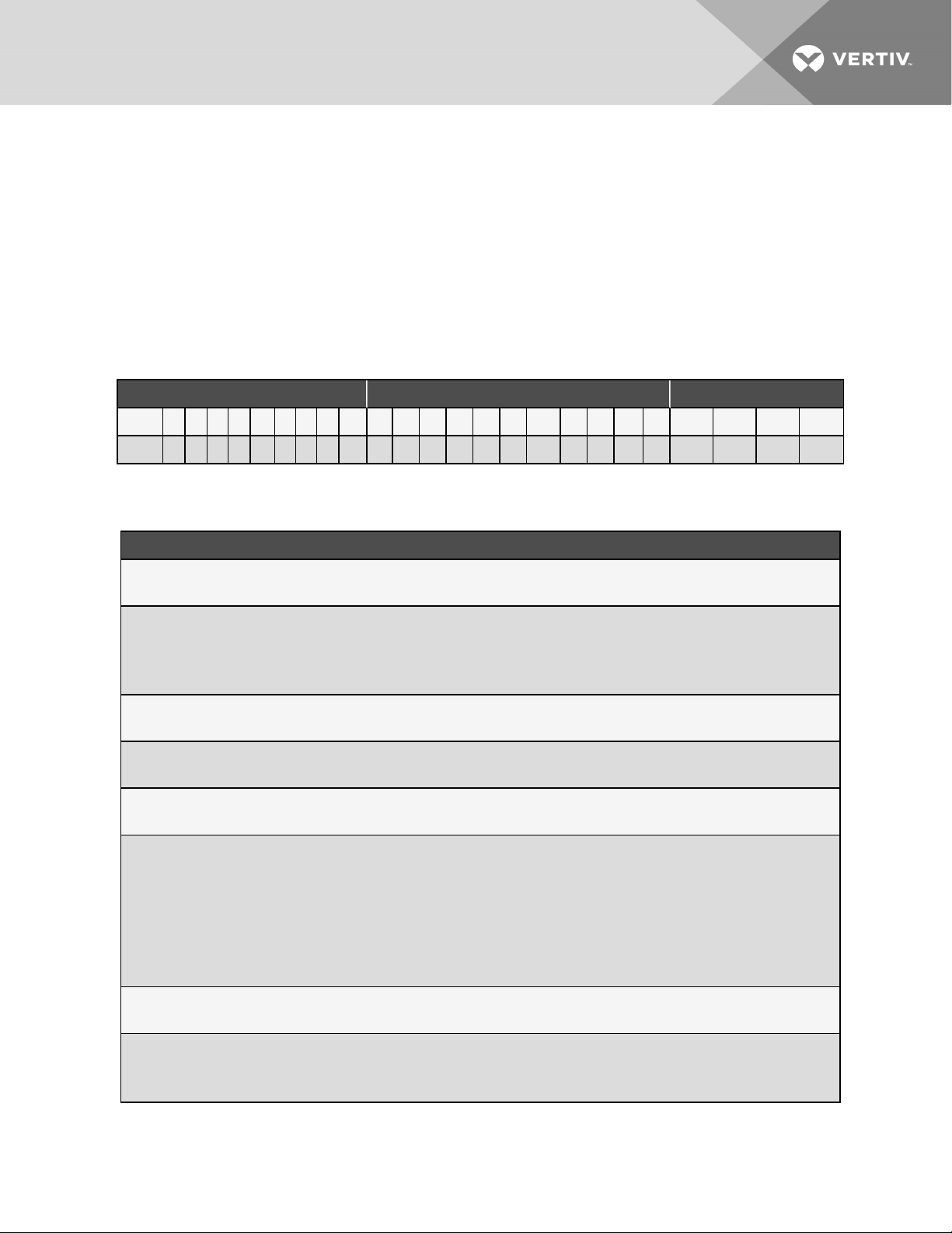
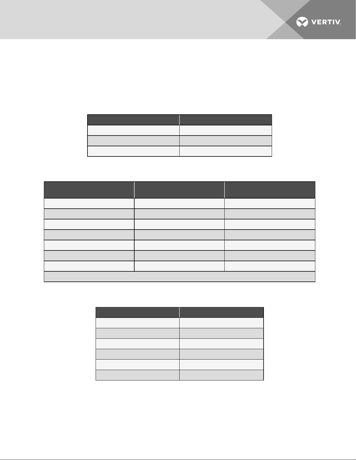
Table 2.1 Mini-Mate 25-Digit Configuration Number
ModelNumber Digits 1 to 10 ModelDetails ModelNumber Digits11to14
1 2 3 4 5 6 7 8 9 10 1 1 12 13 14 15 16 1 7 18 19 20 21 22 23 24 25
M T 0 6 0 H E 1 A 0 S H 2 0 D 0 U 0 P 0 0 A # # #
Table 2.2 Model Number Digit Definitions
Digit andDescription
Digits 1 and 2 = Unit Family
MT = Mini-Mat e Ceil ing System
Digits 3, 4, 5 = Nominal Cooli ng C apaci ty
036 = 36kBtuh
048 = 48kBtuh
060 = 60 kBtuh
Digit 6 = Air Di rect ion and Discharge
H = H oriz onta l air flow
Digit 7 = System ty pe
E = Split System evapora tor
Digit 8 = Fan type
1 = Dir ect Dri ve EC mot or (va ria ble-speed)
Digit 9 = Supply power
A = 460V / 3ph / 60 Hz
B = 575V / 3ph / 60 Hz (0 48 a nd 060 models only )
C = 208V / 3ph / 60Hz (0 48 and 060 models only)
D = 230V / 3ph / 60Hz (0 48 and 060 models only)
P = 20 8-230 /1ph/60Hz (0 36 model only)
Y = 20 8-230 /3ph/60 Hz (0 36 model onl y)
Digit 10 = Evaporator T ype
0 =Spli t System evapora tor
Digit 11 = Humidifier
0 = No humidifier
S = Steam-gen caniste r humidifier
2 Nomenclature an d Components
7
Page 12
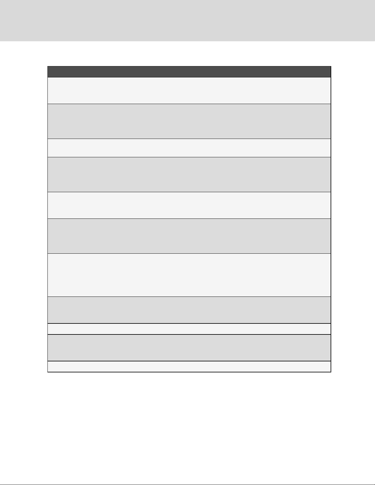
Table 2.2 Model Number Digit Definitions (continued)
Digit andDescription
Digit 12 = Display t ype
H = 9-i n. r emote display, I ntell iSlot -based monitori ng ( 048 and 0 60 models onl y)
1 = 9-in. remote display , iCOM-based monitor ing (036 model only)
Digit 13 = R eheat
0 = No reheat
2 = Elect ri c reheat
5 = SCR reheat ( 048 and 0 60 models only )
Digit 14 = Coi l, Valve, Pr essure
0 = Split Sy stem evaporat or
Digit 15 = H igh-v olta ge options
D = Non-locki ng di sconnect, 5k SCCR ( 048 and 0 60 models onl y)
L = Locking disconnect, 5kA SCCR (0 36 model only)
M = Locking disconnect, 65k SCCR (0 48 a nd 0 60 models onl y)
Digit 16 = Low-vol tage options
0 = None
L = Low vol tage te rminal pac kage (LVTP)
Digit 17 = Monitoring Cards
0 = No card, Intel liSlot onl y (048 and 0 60 models onl y)
U = IS-UNITY- DP card, factor y-i nstall ed (048 a nd 0 60 models only)
B = BACnet, Modbus, SNMP using iCOM board (036 model only)
Digit 18 = Sensors
0 = None
S = Smoke sensor
H = H igh Temperat ure sensor
F = Smoke and high temper atur e sensor
Digit 19 = P acka ging
P = Domesti c
C = Wood cr at e export
Digits 20, 21 = Future use
Digit 22 = Factory configurati on code
A = No SFA’s ( Any Alpha lett er exc ept S)
S = SFA
Digit23-25 = Factory Configuration Number
8
Vertiv | Liebert® Min i-Mate™ Install er/User Guide
Page 13
2.2 Component Location
The unit component locations are described in the submittal documents included in the Submittal Drawings on page63.
The following tables list the relevant documents by number and title.
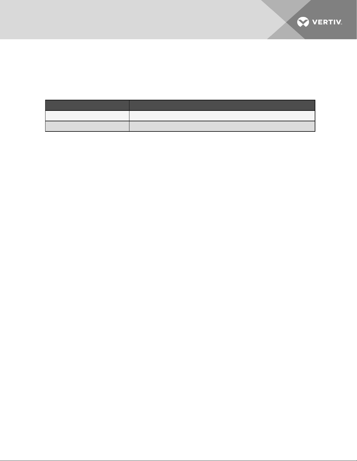
Table 2.3 Component Location Drawings
Document Number Title
DPN004808 Evaporator Unit, 3 Ton
DPN004179 Evaporator Unit, 4 Ton and 5 Ton
2 Nomenclature an d Components
9
Page 14

This page intentionally left blank
10
Vertiv | Liebert® Min i-Mate™ Install er/User Guide
Page 15
3 PRE-INSTALLATION PREPARATIONANDGUIDELINES
NOTE: Before installing unit, determine whether any building alterations are required to run piping, wiring and duct
work. Follow all unit dimensional drawings and refer to the submittal engineering dimensional drawings of individual
units for proper clearances.
Refer to Model Number Digit Definitions on page7, and submittal drawings to determine the type of system being installed
and anticipate building alterations, piping and duct work needed.
The unit dimensions, pipe connection locations, and piping schematics are described in the submittal documents included
in the Submittal Drawings on page63.
• Confirm that the room is properly insulated and has a sealed vapor barrier.
• For proper humidity control, keep outside or fresh air to an absolute minimum (less than 5% of total air
circulated in the room).
• Install the units as close as possible to the largest heat load.
• Allow at least the minimum recommended clearances for maintenance and service. See the appropriate
submittal drawings for dimensions.
• We recommend installing a water detection system. Contact your Vertiv representative for information.
3.1 Planning Dimensions
The unit dimensions described in the submittal documents included in the Submittal Drawings on page63.
The following table lists the relevant documents by number and title.
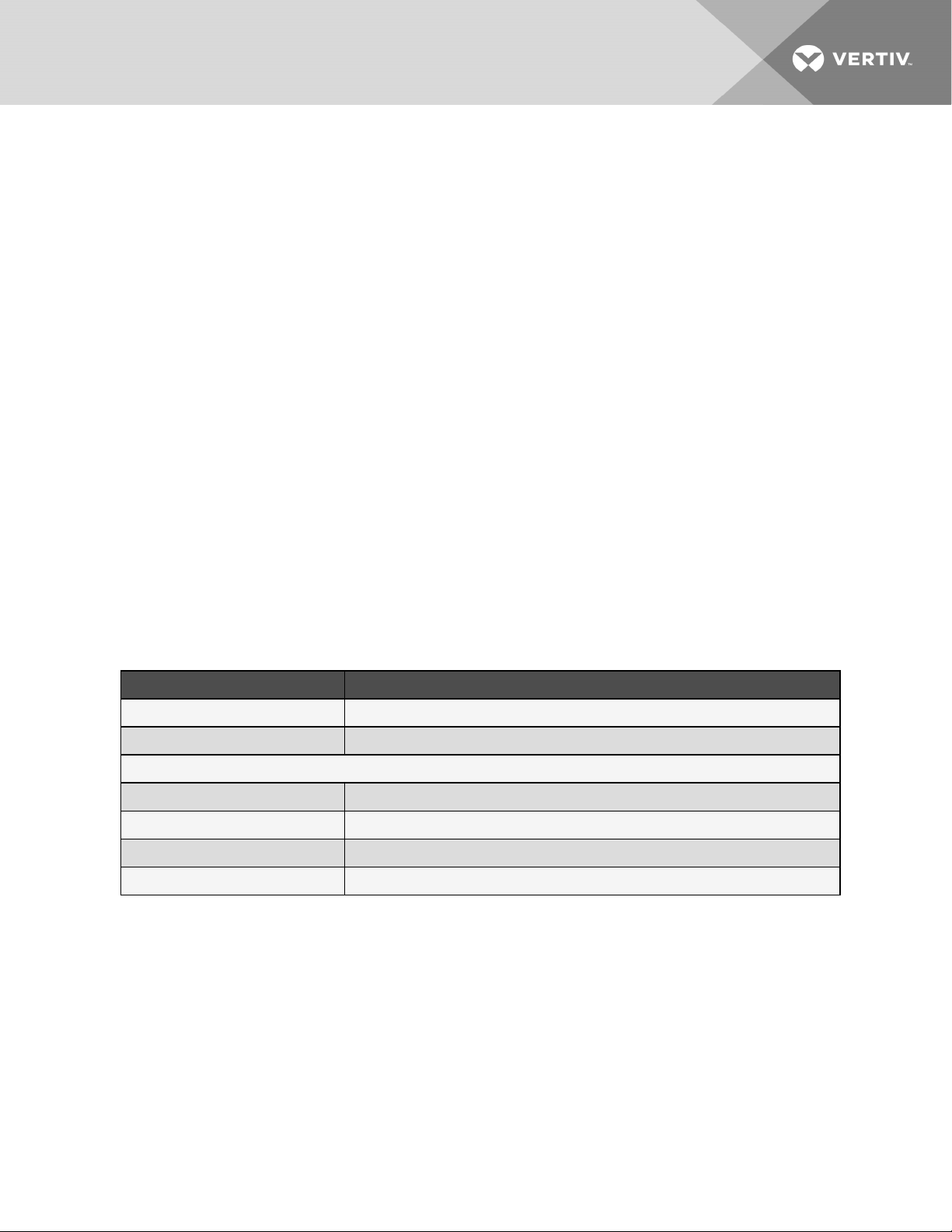
Table 3.1 Dimension Planning Drawings
Document Number Title
DPN004800 Cabinet dimensions, 3 ton DX m odule
DPN004055 Cabinet dimensions, 4 tonand 5 ton DX m odule
Filter and Ducting O ptions
DPN004805 Dimensional data, filter box and duct flange, 3 ton
DPN004807 Dimensional data, air distributionplenum 3 ton
DPN004166 Dimensional data, filter box and duct flange, 4 and 5 ton
DPN004842 Dimensional data, bottom discharge grille, 4 and 5 ton
3.2 Location Considerations
When determining installation locations, consider that these units contain water and that water leaks can cause damage to
sensitive equipment and furniture below.
The evaporator is usually mounted above the dropped ceiling and must be securely mounted to the roof structure. For
ducted systems, the evaporator may be located in a different room. See Guidelines for Ducted Systems on page37 for
additional guidelines. For a split system with an air cooled, outdoor condensing unit, the condensing unit may be mounted
on the roof or remotely in an outdoor area. See Location Considerations for Outdoor Condensing Unit on the next page for
additional guidelines.
Refer to Refrigerant Line Sizes and Equivalent Lengths on page18 for maximum refrigerant line lengths.
3 Pr e-inst allation Preparationand Guidelin es
11
Page 16

The ceiling and ceiling supports of existing buildings may require reinforcement. See Mini-Mate Unit Weights on the facing
page. Be sure to follow all applicable national and local codes.
For a split system with an indoor condensing unit, the condensing unit may be:
• Installed above the suspended ceiling near the evaporator.
• In any remote indoor area, subject to the requirements detailed in Table 4.3 on page17.
Refer to Refrigerant Line Sizes and Equivalent Lengths on page18 for maximum refrigerant line lengths.
Install the ceiling mounted unit over an unobstructed floor space if possible. This will allow easy access for routine
maintenance or service. Do not attach additional devices (such as smoke detectors, etc.) to the housing, as they could
interfere with the maintenance or service.
Do not install units in areas where normal unit operating sound may disturb the working environment.
3.2.1 Location Considerations for Outdoor Condensing Unit
Observe the following when planning the installation of the outdoor unit:
• To ensure a satisfactory air supply, locate air cooled condensing units in an environment with clear air, away
from loose dirt and foreign matter that may clog the coil.
• Condensing units must not be located in the vicinity of steam, hot air, or fume exhausts or closer than 18 inches
from a wall, obstruction or adjacent unit.
• Avoid areas where heavy snow will accumulate at air inlet and discharge locations.
• The condensing unit should be located for maximum security and maintenance accessibility. Avoid groundlevel sites with public access. Install a solid base, capable of supporting the weight of the condensing unit.
• The base should be at least 2in. (51mm) higher than the surrounding grade and 2 in. (51mm) larger than the
dimensions of the condensing unit base. For snowy areas, a base of sufficient height to clear snow accumulation
must be installed.
Before beginning, refer to Piping and Refrigerant Requirements on page15 for unit placement, piping guidelines, and
refrigerant charge requirements for your system.
3.3 Connections and System Setup
• The unit requires a drain, which must comply with all applicable codes. This drain line may contain boiling
water. See Drain Line Installation Requirements on page28, for details.
• Electrical service is required for all models. Electrical service must conform to national and local electrical
codes. See equipment nameplate for details.
• Plan the routing of wiring, piping, and duct work to the unit. Refer to the appropriate piping connection location
drawings, piping schematics, and electrical connection drawings for your system in .
NOTE: Seal openings around piping and electrical connection to prevent air leakage. Failure to do so could reduce the
unit’s cooling performance.
3.4 Operating Conditions
The Liebert® Mini-Mate must be operated in a conditioned space within the operating envelope that ASHRAE recommends
for data centers. Operating the Mini-Mate outside of this envelope can decrease equipment reliability. Refer to ASHRAE’s
publication, “Thermal Guidelines for Data Processing Environments.”
12
Vertiv | Liebert® Min i-Mate™ Install er/User Guide
Page 17
3.4.1 Cooling, Humidification, and Dehumidification
For operation in the Cooling, Humidification, or Dehumidification modes, the Liebert® Mini-Mate unit’s return air
requirements for proper unit operation are:
• Maximum dew point of 59°F (15°C)
• Minimum 65°F (20°C)DB
• Maximum 85°F (29.4°C) DB
3.4.2 Heating
For operation in the Heating mode, the Liebert® Mini-Mate unit’s return air requirements for proper unit operation are:
• Maximum humidity: less than 80% RH and less than 64°F (17.8°C) dew point.
• Maximum dry bulb of 80°F (27°C)
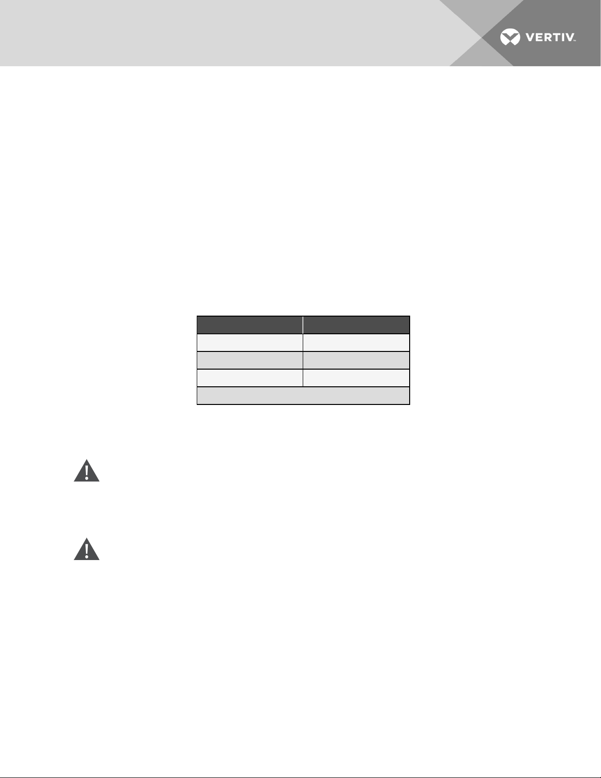
3.5 Mini-Mate Unit Weights
Table 3.2 Mini-Mate Unit Weights
Model# Weight, lb(kg)
MT036 328 (149)
MT048* 498 (226)
MT060* 498 (226)
* for 57 5-V units, add 32lb (14.5kg)
3.6 Equipment Inspection and Handling
SAFETY INFORMATION
WARNING! Risk of improper moving, lifting, or handling of the unit. Can cause equipment damage, injury or
death. Read all of the following instructions and verify that all lifting and moving equipment is rated for the
weight of the unit before attempting to move, lift, remove packaging from or prepare the unit for installation.
Unit weights are specified in section Mini-Mate Unit Weights above.
CAUTION: Risk of contact with sharp edges, splinters, and exposed fasteners. Can cause injury. Only
properly trained and qualified personnel wearing appropriate, OSHA-approved PPE should attempt to move,
lift, remove packaging from or prepare the unit for installation.
NOTICE
Risk of doorway/hallway interference. Can cause unit and/or structure damage. The unit may be too large to fit
through a doorway or hallway while on the skid. Measure the unit and passageway dimensions, and refer to the
installation plans prior to moving the unit to verify clearances.
NOTICE
Risk of damage from forklift. Can cause unit damage. Keep tines of the forklift level and at a height suitable to
fit below the skid and/or unit to prevent exterior and/or underside damage.
3 Pr e-inst allation Preparationand Guidelin es
13
Page 18

NOTICE
Risk of improper storage. Keep the unit upright, indoors and protected from dampness, freezing temperatures
and contact damage.
Upon arrival of the unit and before unpacking:
• Verify that the labeled equipment matches the bill of lading.
• Carefully inspect all items for visible or concealed damage.
• Report damage immediately to the carrier and file a damage claim with a copy sent to Vertiv or to your sales
representative.
Equipment Recommended for Handling the Unit:
• Forklift
• Pallet jack
14
Vertiv | Liebert® Min i-Mate™ Install er/User Guide
Page 19
4 PIPING AND REFRIGERANT REQUIREMENTS
All fluid and refrigeration connections to the unit, with the exception of the condensate drain and humidifier supply line, are
sweat copper. Factory installed piping brackets must not be removed. Field installed piping must be installed in
accordance with local codes and must be properly assembled, supported, isolated, and insulated. Avoid piping runs
through noise sensitive areas, such as office walls and conference rooms.
Refer to specific text and detailed diagrams in this manual for other unit specific piping requirements.
The following pipe connections are required:
• Refrigerant piping connections between the evaporator unit and the condensing unit.
• A drain line from the unit or a drain line from the optional condensate pump (if applicable).
• A drain line from the secondary drain pan (if applicable).
• A water supply line to the optional humidifier (if applicable).
• On water/glycol systems: connections to a water or glycol loop. See Water/Glycol Loop Piping Guidelines on
page21, for additional requirements.
The pipe connection locations, piping general arrangement, and schematics are described in the submittal documents
included in the Submittal Drawings on page63.
The following tables list the relevant documents by number and title.
Table 4.1 Piping General Arrangement Drawings
Document Number Title
Air Cooled System
DPN004060 Pipingarrangement, 3, 4 and 5 ton split system
Water/Glycol CooledSystem
DPN004893 Piping arrangement, 3, 4 and 5 ton split system
Table 4.2 Piping Connection Drawings
Document Number Title
DPN004801 Primary connection loca tions, 3 ton DX m odule
DPN004806 Condensate pump c onnection locations, 3 ton
DPN004056 Primary connection locations, 4 ton and 5 ton DX module
DPN004077 Condensate pump connection locations, 4 ton and 5 ton
4.1 Refrigerant Piping and Charging
WARNING! Risk of over-pressurization of the refrigeration system. Can cause explosive discharge of highpressure refrigerant, loss of refrigerant, environmental pollution, equipment damage, injury, or death. This
unit contains fluids and gases under high pressure. Use extreme caution when charging the refrigerant
system. Do not pressurize the system higher than the design pressure marked on the unit's nameplate.
4 Pipin g and Refrigeran t Requirements
15
Page 20

Consult local building and plumbing codes for installation requirements of additional pressure relief devices when isolation
valves are field installed. Do not isolate any refrigerant circuits from over-pressurization protection.
NOTICE
Risk of oil contamination with water. Can cause equipment damage.
Liebert®Mini-Mate systems require the use of POE (polyolester) oil. POE oil absorbs water at a much faster
rate when exposed to air than previously used oils. Because water is the enemy of a reliable refrigeration
system, extreme care must be used when opening systems during installation or service. If water is absorbed
into the POE oil, it will not be easily removed and will not be removed through the normal evacuation process. If
the oil is too wet, it may require an oil change. POE oils also have a property that makes them act as a solvent
in a refrigeration system. Maintaining system cleanliness is extremely important because the oil will tend to
bring any foreign matter back to the compressor.
4.1.1 Refrigerant Piping Guidelines forAir CooledSystems
• Evaporators and condensing units ship with an inert gas holding charge. Do not vent the evaporator and
condensing unit until all refrigerant piping is in place, ready for connection to the unit and condensing unit.
• Use copper piping with a brazing alloy with a minimum temperature of 1350°F (732°C), such as Sil-Fos. Avoid
soft solders, such as 50/50 or 95/5.
• Use a flow of dry nitrogen through the piping during brazing to prevent formation of copper oxide scale inside
the piping. When copper is heated in the presence of air, copper oxide forms. POE oils will dissolve these
oxides from inside the copper pipes and deposit them throughout the system, clogging filter driers and
affecting other system components.
• A pure dry nitrogen flow of 1-3 ft3/min (0.5-1.5 l/s) inside the pipe during brazing is sufficient to displace the air.
Control the flow using a suitable measuring device.
• Ensure that the tubing surfaces to be brazed are clean and that all burrs have been removed from the ends of
the tubes.
• Ensure that all loose material has been cleaned from inside the tubing before brazing.
• Protect all refrigerant line components within 18in. (460mm) of the brazing site by wrapping them with a wet
cloth or with a suitable heat sink compound.
• Isolate piping from building using vibration isolating supports.
• When sealing openings in walls and to reduce vibration transmission, use a soft, flexible material to pack
around the tubes to prevent tube damage.
• When installing remote condensing units above the evaporator, the suction gas lines should be trapped at the
evaporator. These traps will retain refrigerant oil in the off cycle. When the unit starts, oil in the traps is carried
up the vertical risers and returns to the compressors. For rises over 25ft (7.6m), trap every 20ft (6m)or
evenly-divided.
• Consult factory if piping run exceeds 150ft(46m) equivalent length.
• Keep piping clean and dry, especially on units with R-410A refrigerant.
• Avoid piping runs through noise sensitive areas.
• Do not run piping directly in front of discharge air stream.
• Refrigerant oil – do not mix oil types.
Refer to ASHRAE Refrigeration Handbook for general, good practice refrigeration piping.
NOTE: All indoor and outdoor suction line piping must have 1/2 in. minimum of insulation. All outdoor insulation must
be UV and ozone resistant.
16
Vertiv | Liebert® Min i-Mate™ Install er/User Guide
Page 21
NOTE: Proper safety equipment and proper refrigeration tools are required when working with R-410A refrigerant.
Check unit serial tag for correct refrigerant type before topping off or recharging a system.
NOTE: Refrigerant R-410A uses a POE (polyolester) lubricant. The refrigerant must be introduced and charged from
the cylinder only as a liquid.
NOTE: When installing field piping, you must take care to protect all refrigerant lines from the atmosphere especially
when using refrigerants with POE oils. Do not allow the piping to stand open to air for more than 15minutes. Units
designed for R-410A have a compressor that contains POEoil, which quickly absorbs water from the air. The longer
that the refrigerant piping is left open to air, the harder it will be to fully evacuate the system. If left open too long, the
POE oil may require replacement to achieve the required vacuum level.
• Refer to Refrigerant Line Sizes and Equivalent Lengths on the next page, for recommended refrigerant piping
sizes based on equivalent pipe lengths.
• Refer to the condensing unit's Installer/User Guide for the complete charging procedure of the system.
4.1.2 Piping when Condensing Unit is Above or Below Evaporator
Refer to Table 4.3 below for the maximum vertical rise/fall between condensing unit and evaporator.
When installing remote condensing units above the evaporator, trap the suction gas line at the evaporator as shown in
Figure 4.1 below. Traps recommended at the base of riser exceeding 5 ft. (1.5 m) and every 20 ft. (6 m) of vertical rise. This
trap will retain refrigerant oil during the "Off" cycle. When the unit starts, oil in the trap is carried up the vertical riser and
returns to the compressor.
When installing remote condensing units below the evaporator, trap the suction gas line with an inverted trap the height of
the evaporator as shown in the following figure. This prevents refrigerant migration to the compressor during "Off" cycles.
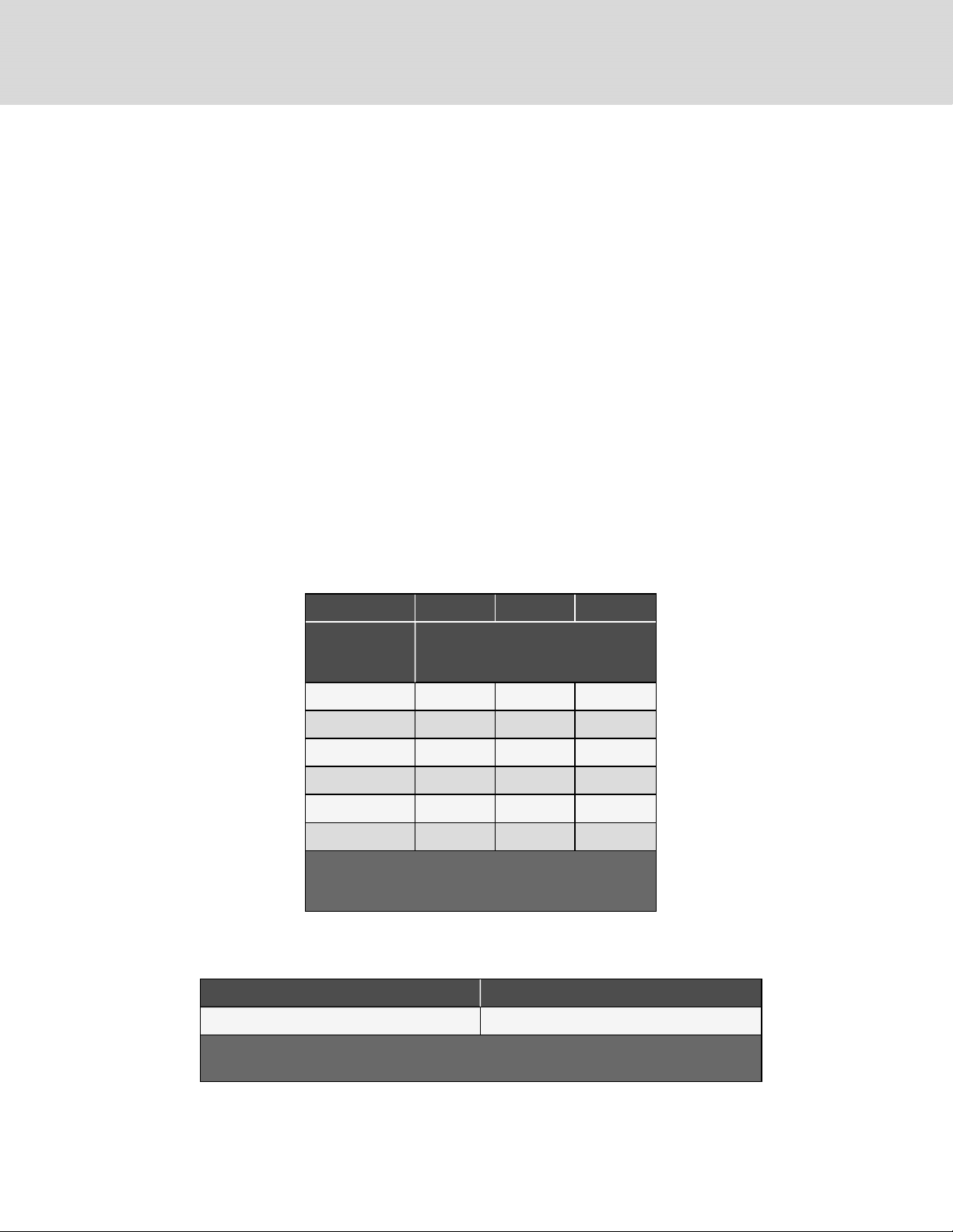
Table 4.3 Pipe Length and Condensing Unit Elevation Relative to Evaporator
Maximum Equivalent Pipe Length, ft. (m)
150 (45) 50 (15) 15 (4.6)
Maximum CondensingUnit Level Above
Evaporator, ft. (m)
Maximum CondensingUnit Level Below
Evaporator, ft. (m)
Figure 4.1 Refrigerant Piping Diagram When Condenser is Above or Below Evaporator
NOTE: Any horizontal pipe must be pitched down toward the condensing unit at a minimum rate of 1/2 in. (13 mm) per
10 ft. (3 mm) to assure oil return to compressor.
4 Pipin g and Refrigeran t Requirements
17
Page 22
4.2 Refrigerant Line Sizes and Equivalent Lengths
The following tables list the information required to field install the refrigerant piping for the system.
Table 4.4 Recommended Refrigerant Line Sizes, O.D.cubyEquivalentLength
3 Ton 4 Ton 5 Ton
Equivalent Length, ft (m)
50 (15) 7/8 1/2 7/8 1/2 1-1/8 1/2
75 (23) 7/8 1/2 1-1/8 1/2 1-1/8 5/8
100 (30) 7/8 1/2 1-1/8 5/8 1-1/8 5/8
125 (38) 7 /8 1/2 1-1/8¹ 5/8 1-1/8 5/8
150 (45) 7/8 1/2 1-1/8 5/8 1 -1/8 5/8
Consult factor y for proper line sizing for runs l onger than maximum equival ent length shown.
1.Use one li ne size smaller on suction lines for v ert ica l risers.
Source: DPN000 788 Rev. 13
Suction Liquid Suction Liquid Suction Liquid
18
Vertiv | Liebert® Min i-Mate™ Install er/User Guide
Page 23
4.2.1 Refrigerant Charge Requirements forAir Cooled Systems
To calculate the charge requirements:
1. Determine the charge for your units by model number from the following tables.
2. Determine the charge for the piping by line size and length.
3. Add these all together to obtain the total refrigerant charge for your system.
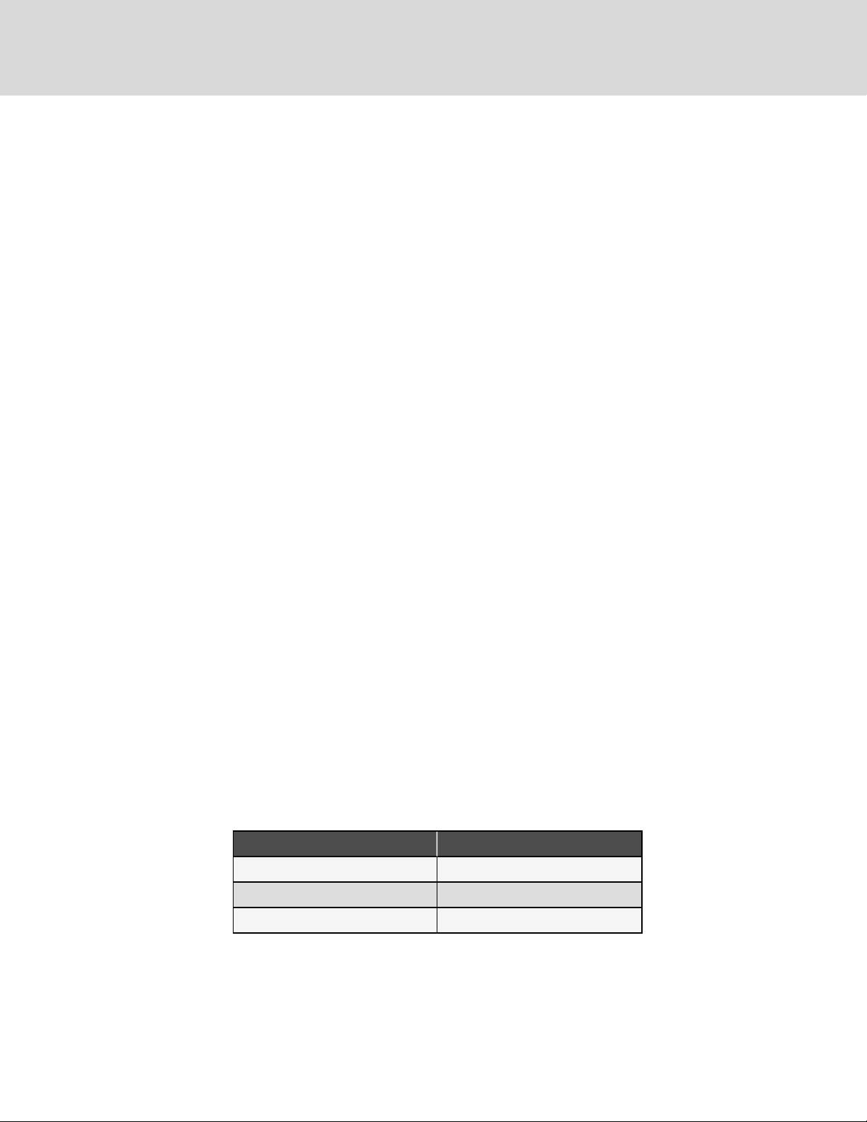
Table 4.5 Indoor Evaporator Approximate R-410ARefrigerant Charge
Model# Charge, lb (kg)
MT036HE 1 (0.45)
MT048HE 2.2 (1.0)
MT060HE 2.2 (1.0)
Table 4.6 Interconnecting Piping Refrigerant Charge for R-410A using Type L Copper Tube
Line Size,
O.D., in.
3/8 3.2 (1.4) —
1/2 5. 9 (2.7) 0.2 (0.1 )
5/8 9.6 (4.3) 0.4 (0.2)
LiquidLine, lb/100ft (kg/30m) Suction Line, lb/100ft (kg/30m)
3/4 14.3 (6.4) 0.6 (0.3)
7/8 19.8 (8.8) 0.8 (0.4)
1-1/8 33. 8 (15.1) 1.4 (0.6)
1-3/8 51.5 (23.0) 2.1 (1.0 )
Source:DPN003099 Rev. 1
Table 4.7 PFD Condensing Unit R-410A Refrigerant Charge
Model# Charge, lb(kg)
PFD037A-*L1 13.4 (6.1)
PFD037A-*H1 27 (12.2)
PFD054A-*L1 27 (12.2 )
PFD067A-*L1 27 (12.2)
PFDZ67A-*L1 57 (25.8)
PFD067A-*H1 57 (25.8)
4 Pipin g and Refrigeran t Requirements
19
Page 24
4.2.2 Additional Oil Requirements for Digital Scroll Compressors
NOTICE
Risk of improper compressor lubrication. Can cause compressor and refrigerant system damage.
Failure to use oil types, viscosities and quantities recommended by the compressor manufacturer may reduce
compressor life and void the compressor warranty.
• Do not mix polyolester (POE) and mineral-based oils.
• Do not mix oils of different viscosities.
• Consult your Vertiv sales representative, visit https://www.Vertiv.com/en-us/support/, or contact the
compressor manufacturer if questions arise.
System charges may require additional oil charge to be added. See Table 4.8 below, for the amount required for various
system charge levels.
After the system has been fully charged with refrigerant, use a hand pump to add the additional oil at the suction side of the
system while the system is running.
On the tag marked “Oil Added Field Service Record,” attached to each compressor, record the date the oil was added and
the amount of oil added.
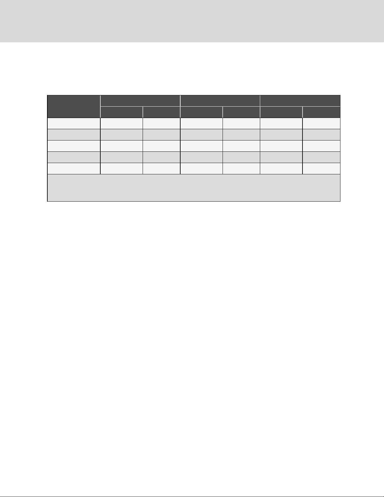
Table 4.8 Additional Oil Required per Refrigerant
Charge
3 Ton 4 Ton 5 Ton
Refrigerant System
Charge per Circuit,
lb (kg)*
<40 (18.1) 0 0 0
40 (18.1) 4 (120) 4 (120) 6 (180)
50 (22.7) 6 (180) 6 (180) 9 (270)
60 (27.2) 8 (240) 8 (240) 12 (350)
70 (31.8) 10 (300) 10 (300) 15 (440)
80 (36.3) 12 (350) 12 (350) 18 (530)
* System Charge = indoor unit + condensing unit + refrigerant lines.
For system charges over 80lb. (36.3 kg), consult your Vertiv representative.
Source: DP N003950 Rev 5.
Additional Oil Required Per Circuit, oz (ml)
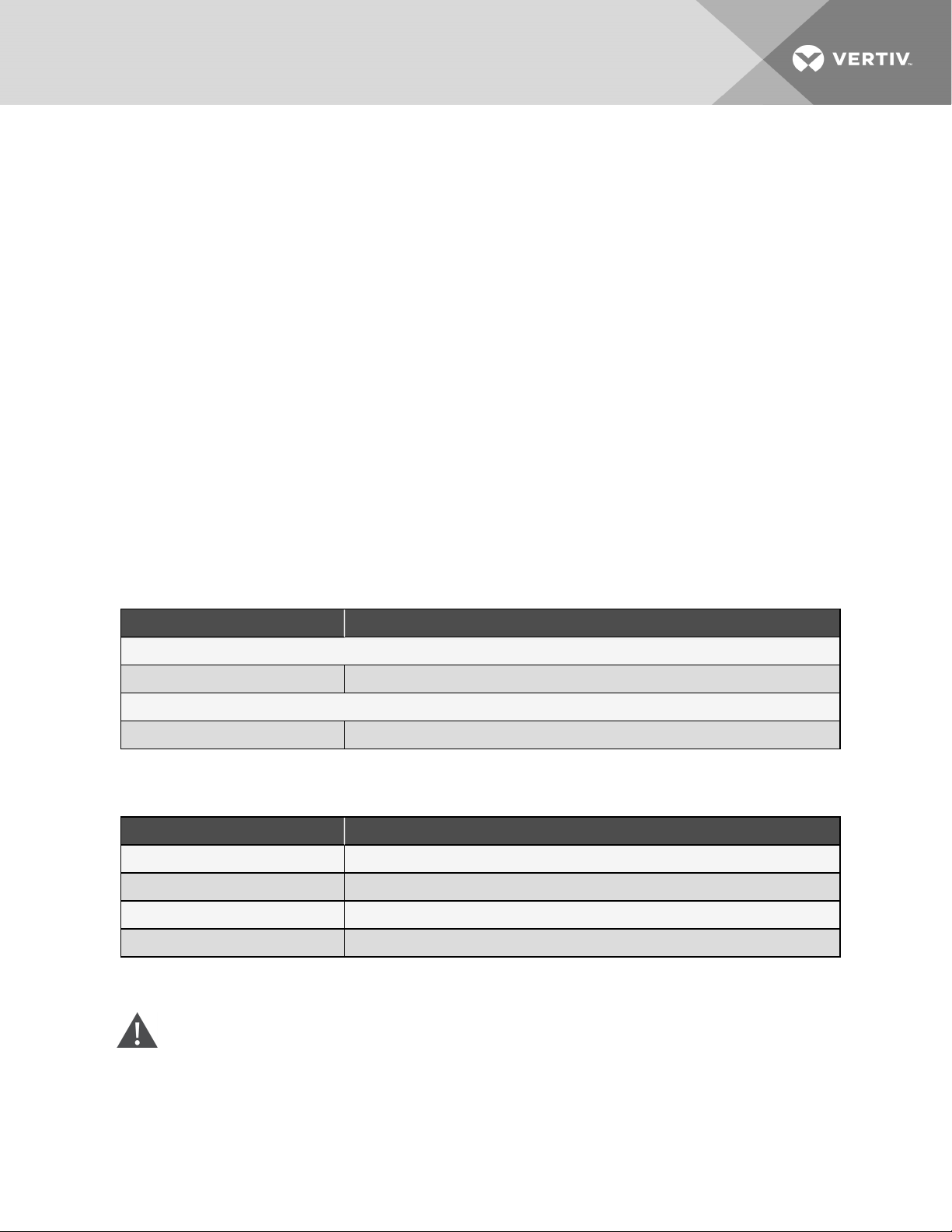
Table 4.9 Compressor Oil types for R-410A Refrigerant
Compressor Type Oil Type
Copeland Digital Scroll POE Oil - ISO 32 Centistoke Viscosity
1. Use CopelandP OE Oil ULTRA 32-3MAF or other Copeland approved oils.
Source: DP N003950. Rev. 5
1
20
Vertiv | Liebert® Min i-Mate™ Install er/User Guide
Page 25

4.3 Water/Glycol Loop Piping Guidelines
WARNING! Risk of improper piping installation, leak checking, fluid chemistry and fluid maintenance can
cause equipment damage and personal injury. Installation and service of this equipment should be done only
by qualified personnel who have been specially trained in the installation of air conditioning equipment and
who are wearing appropriate, OSHA approved PPE.
NOTICE
Risk of frozen pipes and corrosion from improper coolant mixture. Can cause water leaks resulting in
equipment and building damage.
When the cooling unit or piping may be exposed to freezing temperatures, charge the system with the proper
percentage of glycol and water for the coldest design ambient temperature. Automotive antifreeze is
unacceptable and must NOT be used in any glycol fluid system. Use only HVAC glycol solution that meets the
requirements of recommended industry practices. Do not use galvanized pipe.
NOTICE
Risk of piping system corrosion and freezing fluids. Can cause leaks resulting in equipment and expensive
building damage. Cooling coils and piping systems are at high risk of freezing and premature corrosion. Fluids
in these systems must contain an inhibitor to prevent premature corrosion.
The system coolant fluid must be analyzed by a competent fluid treatment specialist before start up to
establish the inhibitor level and evaluated at regularly scheduled intervals throughout the life of the system to
determine the pattern of inhibitor depletion. The fluid complexity and variations of required treatment
programs make it extremely important to obtain the advice of a competent and experienced fluid treatment
specialist and follow a regularly scheduled coolant fluid system maintenance program.
Fluid chemistry varies greatly as do the required additives, called inhibitors, that reduce the corrosive effect of
the fluids on the piping systems and components.
The chemistry of the coolant fluid used must be considered, because some sources may contain corrosive
elements that reduce the effectiveness of the inhibited formulation. Sediment deposits prevent the formation of
a protective oxide layer on the inside of the coolant system components and piping. The coolant fluid must be
treated and circulating through the system continuously to prevent the buildup of deposits and/or growth of
bacteria. Proper inhibitor maintenance must be performed to prevent corrosion of the system.
Consult fluid manufacturer for testing and maintenance of inhibitors.
Commercial grade coolant fluid is generally less corrosive to the common metals of construction than water
itself. It will, however, assume the corrosivity of the coolant fluid from which it is prepared and may become
increasingly corrosive with use if not properly inhibited.
Vertiv recommends installing a monitored fluid detection system that is wired to activate the automatic
closure of field installed coolant fluid supply and return shut-off valves to reduce the amount of coolant fluid
leakage and consequential equipment and building damage. The shut-off valves must be sized to close off
against the maximum coolant fluid system pressure in case of a catastrophic fluid leak.
4 Pipin g and Refrigeran t Requirements
21
Page 26
NOTICE
Risk of no-flow condition. Can cause equipment damage.
Do not leave the water/coolant fluid supply circuit in a no-flow condition. Idle fluid allows the collection of
sediment that prevents the formation of a protective oxide layer on the inside of tubes. Keep unit switched On
and water/coolant fluid supply circuit system operating continuously.
• Use copper piping with a brazing alloy with a minimum temperature of 1350°F (732°C), such as Sil-Fos. Avoid
soft solders, such as 50/50 or 95/5.
• Follow local piping codes and safety codes.
• Qualified personnel must install and inspect system piping.
• The water/glycol cooled system will operate in conjunction with a cooling tower, city water or drycooler.
• Contact a local water consultant regarding water quality, corrosion protection and freeze protection
requirements.
• Install manual shut-off valves at the supply and return line to each unit to permit routine service and
emergency isolation of the unit.
• When the fluid quality is poor, we recommend installing a 16-20# mesh Y-strainer filter in the supply line to
extend the service life of the coaxial condensers. These filters must be easily replaced or cleaned.
• Install a monitored, fluid-detection system that is wired to activate the automatic closure of field installed
coolant fluid supply and return shut-off valves to reduce the amount of coolant fluid leakage and consequential
equipment and building damage. The shut-off valves must be sized to close off against the maximum coolant
fluid system pressure in case of a catastrophic fluid leak.
Coolant Regulating Valve Requires No Adjustment
Water/glycol cooled units include a coolant flow regulating valve that is factory adjusted and should not need field
adjustment.
Contact Vertiv technical support before making any adjustments.
4.3.1 Refrigerant Charge Requirements forWater/Glycol Cooled Systems
To calculate the charge requirements:
1. Determine the charge for your units by model number from the following tables.
2. Determine the charge for the piping by line size and length.
3. Add these all together to obtain the total refrigerant charge for your system.
Table 4.10 Water/Glycol, Indoor Condenser R-410A Refrigerant Charge
Model# Charge, lb(kg)
MTC38W 4.2 (1.9)
MTC55W 4.2 (1.9)
MTC69W 4.2 (1.9)
22
Vertiv | Liebert® Min i-Mate™ Install er/User Guide
Page 27
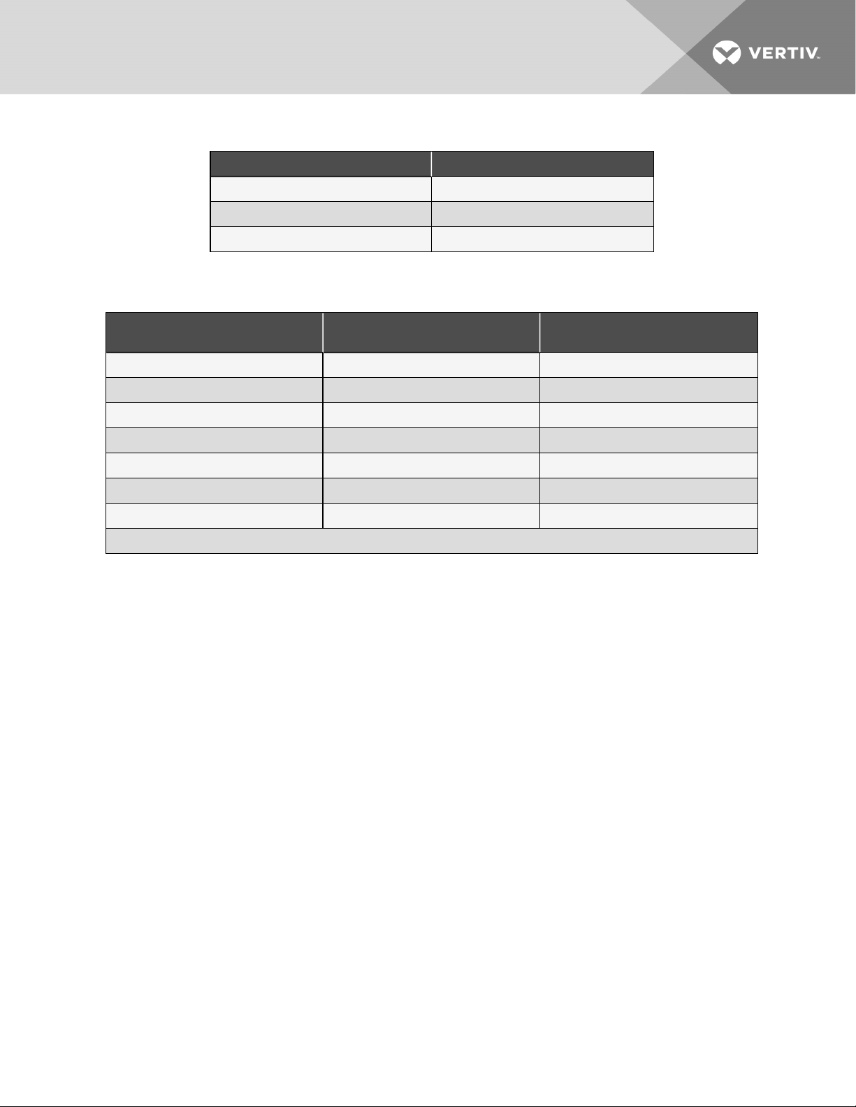
Table 4.11 Indoor Evaporator Approximate R-410ARefrigerant Charge
Model# Charge, lb (kg)
MT036HE 1 (0.45)
MT048HE 2.2 (1.0)
MT060HE 2.2 (1.0)
Table 4.12 Interconnecting Piping Refrigerant Charge for R-410A Using Type L Copper Tube
Line Size,
O.D., in.
3/8 3.2 (1.4) —
1/2 5. 9 (2.7) 0.2 (0.1 )
5/8 9.6 (4.3) 0.4 (0.2)
3/4 14.3 (6.4) 0.6 (0.3)
7/8 19.8 (8.8) 0.8 (0.4)
1-1/8 33. 8 (15.1) 1.4 (0.6)
1-3/8 51.5 (23.0) 2.1 (1.0 )
Source:DPN003099 Rev. 1
LiquidLine, lb/100ft (kg/30m) Suction Line, lb/100ft (kg/30m)
4.3.2 Evacuation and Leak Testing Water/Glycol Cooled Systems
For proper leak check and evacuation, you must open all system valves and account for all check valves, see Figure 4.2 on
the next page.
4 Pipin g and Refrigeran t Requirements
23
Page 28
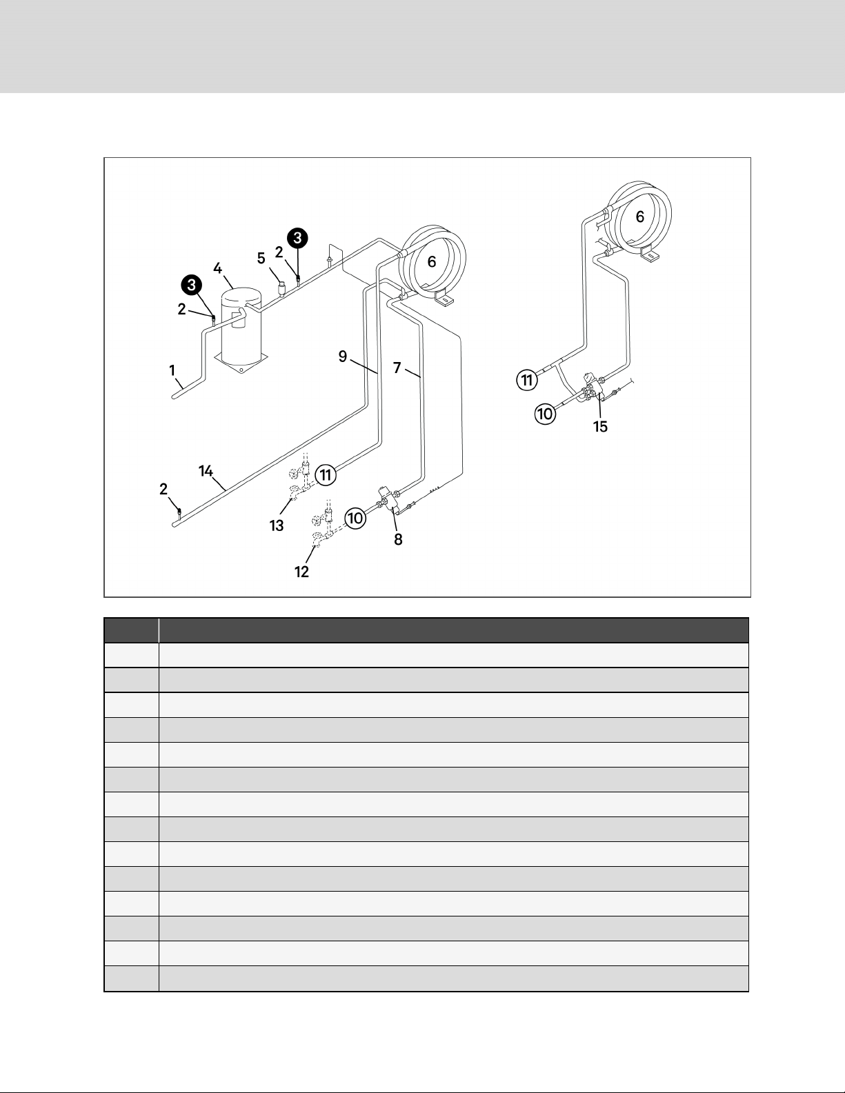
Figure 4.2 Valves and Connections for Water/Glycol Condensing Unit
Item Description
1 Suction line
2 Schrader port with v alve core
3 Apply a manifold gauge hose on the suction line and discharge line Schrader port.
4 2-stage scroll compressor
5 High-pressure switch
6 Tube-in-tube condenser
7 Water/Glycol supply line
8 2-way water regulating va lve
9 Water/Glycol return line
10 Fluid supply to unit
11 Fluid return from unit
12 Hose bibs (required, field supplied)
13 Shut-off valves (required, field supplied)
14 Liquidline
24
Vertiv | Liebert® Min i-Mate™ Install er/User Guide
Page 29

Item Description
15 3-way water regulating valve (optional)
To evacuate and leak test the system:
1. Connect a manifold gauge hose on the discharge and suction line Schrader ports, open the service valve, and
place a 150Psig(1034kPa)charge of dry nitrogen with a tracer of refrigerant, then check the system for leaks
with a suitable leak detector.
2. After completion of leak testing, release the test pressure, (observe local code) and pull an initial deep vacuum
of 500microns on the system with a suitable pump.
3. After fourhours, check the pressure readings and, if they have not changed, break vacuum with dry nitrogen.
Pull a second and third vacuum to 500 microns or less. Re-check the pressure after twohours.
When the three checks are complete, proceed to Charging Water/Glycol Cooled Systems on the next page.
4 Pipin g and Refrigeran t Requirements
25
Page 30

4.3.3 Charging Water/Glycol Cooled Systems
WARNING! Risk of over-pressurization of the refrigeration system. Can cause explosive discharge of highpressure refrigerant, loss of refrigerant, environmental pollution, equipment damage, injury, or death. This
unit contains fluids and gases under high pressure. Use extreme caution when charging the refrigerant
system. Do not pressurize the system higher than the design pressure marked on the unit's nameplate.
Relieve pressure before cutting into or making connections/disconnections to the piping system. Local
building or plumbing codes may require installing a pressure-relief device in the system. Consult local
building and plumbing codes for installation requirements of additional pressure-relief devices when
isolation valves are field installed. Do not isolate any refrigerant circuit from over-pressurization protection.
CAUTION: Risk of excessive refrigerant line pressure. Can cause tubing and component rupture resulting in
equipment damage and personal injury. Do not close off any field-installed refrigerant-line isolation valves for
repairs unless a pressure-relief valve is field- installed in the line between the isolation valve and the check
valve. The pressure-relief valve must be rated 5% to 10% higher than the system-design pressure. An
increase in ambient temperature can cause the pressure of the isolated refrigerant to rise and exceed the
system-design pressure rating (marked on the unit nameplate).
CAUTION: Risk of contacting caustic substances. Can cause injury. Avoid touching or contacting the gas and
oils with exposed skin. Severe burns will result. Wear appropriate, OSHA-approved PPE when handling
contaminated parts.
NOTICE
Risk of improper refrigerant charging. Can cause equipment damage.
R-410A is a blended refrigerant and must be introduced and charged from the cylinder only as a liquid.
When adding liquid refrigerant to an operating system, it may be necessary to add the refrigerant through the
valve in the compressor suction line. Care must be exercised to avoid damage to the compressor. We
recommend connecting a sight glass between the charging hose and the compressor suction service valve.
This will permit adjustment of the cylinder hand valve so that liquid can leave the cylinder while allowing vapor
to enter the compressor.
To calculate the charge for the system:
1. Check the nameplate on the indoor unit for refrigerant type to use.
2. Refer to Refrigerant Charge Requirements forWater/Glycol Cooled Systems on page22, and calculate the
amount of charge for the system including the evaporator, condensing unit, and interconnecting piping.
3. Accurately weigh-in as much of the system charge as possible before starting the unit.
26
Vertiv | Liebert® Min i-Mate™ Install er/User Guide
Page 31

4.3.4 Optimizing Refrigerant Charge on Water/Glycol Units
1. Operate the unit at full heat load, normal room conditions and normal water/glycol fluid temperatures for a
minimum of 30 minutes before measuring stable unit superheat and sub-cooling temperatures and adjusting
charge levels.
• Condensing temperatures should be in range of 100 to 130°F (38 to 54°C) depending on fluid type and
fluid temperature.
• Full heat load is required to stabilize the system.
2. Attach pressure and temperature instruments to the liquid line of the condensing unit. Measure the initial subcooling.
NOTE: To determine sub-cooling measurement, a liquid line pressure reading (at the factory installed Schrader tap)
must be measured along with the temperature reading on the liquid line. Convert the liquid line pressure reading into
a liquid temperature by utilizing a pressure temperature guide. Subtract the measured temperature from the liquid
saturation temperature. The difference is sub-cooling.
3. Adjust refrigerant charge levels as needed to achieve sub-cooling range of 8 to 10°F (4.4to5.5°C) while
maintaining full load conditions.
4.3.5 Documenting Refrigerant Charge on Water/Glycol Cooled Units
When the unit is charged, you must record the total system charge value on the condensing unit's serial tag. The total
system charge includes the evaporator, condensing unit, and interconnecting lines.
4.4 Drain and Humidifier Piping
The following pipe connections are required:
• A drain line from the evaporator unit drain connection.
• A drain line from the secondary drain pan (if applicable).
• A water supply line to the optional humidifier (if applicable).
NOTICE
Risk of clogged or leaking drain lines and leaking water supply lines. Can cause equipment and building
damage.
This unit requires a water drain connection. Drain lines must be inspected at start-up and periodically, and
maintenance must be performed to ensure that drain water runs freely through the drain system and that lines
are clear and free of obstructions and in good condition with no visible sign of damage or leaks.
Improper installation, application and service practices can result in water leakage from the unit. Water
leakage can result in catastrophic and expensive building and equipment damage and loss of critical data
center equipment.
Do not locate unit directly above any equipment that could sustain water damage.
We recommend installing a monitored fluid detection system to immediately discover and report coolant fluid
system and condensate drain line leaks.
4 Pipin g and Refrigeran t Requirements
27
Page 32

4.4.1 Water Supply Line to the Humidifier
The following is required for units with the optional steam generating humidifier package:
• 1/4 in. (6.4mm) copper compression fitting connection for water inlet.
• The supply pressure range is 10psig to 150psig (69to1034kPa) at 1gpm (3.8(lpm).
• A shut-off valve in the supply line to isolate the humidifier for maintenance.
• Do not supply steam generating humidifier with softened water.
• Do not use hot water source.
• Water conductivity must be in the range of 330-750microsiemens.
To install the water supply:
1. Cut the tube square and remove any burrs.
2. Slide nut, then the sleeve on tube. The threaded end of the nut faces the end of the tube.
3. Insert the tube into the fitting, seating it against the stop shoulder and tighten the nut hand tight to the body.
4. Use a wrench to tighten the nut 1-1/4 to 2-1/4 turns.
NOTICE
Risk of improper tightening of the piping fittings. Can damage fittings and cause leaks.
Use caution not to over tighten or under tighten the piping fittings.
Do not route the humidifier supply line in front of the filter box access panel.
4.4.2 Drain Line Installation Requirements
NOTICE
Risk of water backing up in the drain line. Leaking and overflowing water can cause equipment and building
damage.
Do not install an external trap in the drain line. This line already has a factory installed trap inside the cabinet.
Installation of a second trap will prevent drain water flow and will cause the water to overflow the drain pan.
Sagging condensate drain lines may inadvertently create an external trap.
A 3/4 in. (19.1mm) NPT female connection is provided for the evaporator unit condensate drain. The evaporator drain pan
includes a float switch to prevent operation if the drain line becomes blocked. This line also drains the humidifier, if
applicable.
28
Vertiv | Liebert® Min i-Mate™ Install er/User Guide
Page 33

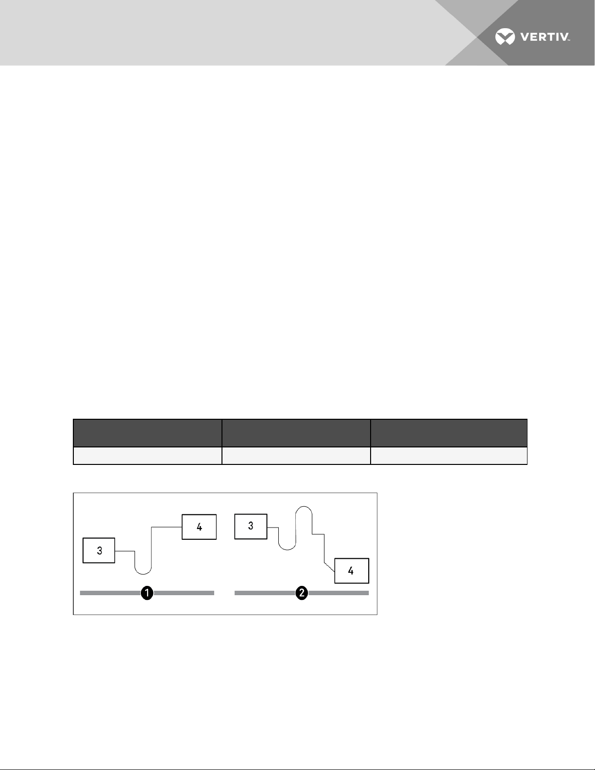
Observe the following requirements and refer to Correct and Incorrect Gravity Drains below, when installing and routing the
drain line:
• The drain line must be sized for 2gpm (7.6 l/m) flow.
• The drain line must be located so it will not be exposed to freezing temperatures.
• The drain should be the full size of the drain connection.
• The drain line must slope continuously away from the unit.
• Do not externally trap the drain line.
• The drain line must be rigid enough that it does not sag between supports, which unintentionally creates traps.
• Use copper or other material suitable for draining water that can reach temperatures up to 212°F (100°C).
• When the evaporator is installed below the level of the gravity fed drain line, the optional condensate pump kit
is required. See Condensate Drain Pump Kit on the next page.
NOTE: Remove the shipping band from the float switch in the evaporator pan before operating the unit.
Figure 4.3 Correct and Incorrect Gravity Drains
Table 4.13 Gravity Fed Drain Line Figure Descriptions
Item Description
1 Correct drain installation.
2 Incorrect. Do not trap externally.
3 Incorrect. Sagging between supports and bowed line ca uses unintentional external traps.
4 Continuous downward slope away from the unit.
5
6 External trap
7 Unintentional trapsfrom bowingof line. Linesmust be rigid enough not to bowor sag between supports, creating a trap.
Unit
4 Pipin g and Refrigeran t Requirements
29
Page 34

4.4.3 Condensate Drain Pump Kit
WARNING! Risk of electric shock. Can cause equipment damage, injury or death. Open all local and remote
electric power supply disconnect switches and verify with a voltmeter that power is off before working within
any electric connection enclosures. Service and maintenance work must be performed only by properly
trained and qualified personnel and in accordance with applicable regulations and manufacturers’
specifications. Opening or removing the covers to any equipment may expose personnel to lethal voltages
within the unit even when it is apparently not operating and the input wiring is disconnected from the
electrical source.
The optional condensate pump kit is required when the evaporator is installed below the level of the gravity fed drain line.
The condensate pump is field installed alongside the evaporator unit.
A 3/4-in. NPT female connection is provided for the evaporator unit condensate drain.
• The drain is trapped internally, do not trap external to unit.
• Size the discharge piping based on the available condensate head.
The installation of the condensate drain pump is described in the submittal documents included in the Submittal Drawings
on page63.
The following tables list the relevant documents by number and title.
Table 4.14 Condensate Drain Pump Drawings
Document Number Title
DPN004806 Condensate pump c onnection locations, 3 ton models
DPN004077 Condensate pump connection locations, 4 and 5 ton models
30
Vertiv | Liebert® Min i-Mate™ Install er/User Guide
Page 35

5 ELECTRICAL CONNECTION REQUIREMENTS
WARNING! Arc flash and electric shock hazard. Open all local and remote electric power supply disconnect
switches, verify with a voltmeter that power is Off and wear appropriate, OSHA-approved personal protective
equipment (PPE) per NFPA 70E before working within the electric control enclosure. Failure to comply can
cause serious injury or death. Customer must provide earth ground to unit, per NEC, CEC and local codes, as
applicable. Before proceeding with installation, read all instructions, verify that all the parts are included and
check the nameplate to be sure the voltage matches available utility power. The Liebert® controller does not
isolate power from the unit, even in the “Unit Off” mode. Some internal components require and receive
power even during the “Unit Off” mode of the controller. The only way to ensure that there is NO voltage
inside the unit is to install and open a remote disconnect switch. Refer to unit electrical schematic. Follow all
local codes.
WARNING! Risk of improper wire sizing/rating and loose electrical connections. Can cause overheated wire
and electrical connection terminals resulting in smoke, fire, equipment and building damage, injury or death.
Use correctly sized copper wire only and verify that all electrical connections are tight before turning power
On. Check all electrical connections periodically and tighten as necessary.
NOTE: Seal openings around piping and electrical connections to prevent air leakage. Failure to do so could reduce
the unit's cooling performance.
NOTICE
Risk of improper power supply connection. Can cause equipment damage and loss of warranty coverage.
Prior to connecting any equipment to a main or alternate power source (for example: back-up generator
systems) for start-up, commissioning, testing, or normal operation, ensure that these sources are correctly
adjusted to the nameplate voltage and frequency of all equipment to be connected. In general, power source
voltages should be stabilized and regulated to within ±10% of the load nameplate nominal voltage. Also, ensure
that no three-phase sources are single phased at any time.
See transformer label for primary tap connections. Installer will need to change transformer primary taps if
applied unit voltage is other than pre-wired tap voltage.
NOTE: For 208 VAC, 3 ton applications, the low voltage transformer tap must be changed. Refer to the electrical
schematic.
All power and control wiring and ground connections must be in accordance with the National Electrical Code and local
codes. Refer to the equipment serial tag data for electrical requirements.
A manual electrical disconnect switch should be installed in accordance with local codes and distribution system. Consult
local codes for external disconnect requirements.
NOTE: Input power requirements: For 3 phase units, only 3 power wires and an earth ground are required.
The electrical connections are described in the submittal documents included in the Submittal Drawings on page63.
The following table lists the relevant documents by number and title.
5 Electrical Connection Requirements
31
Page 36

Table 5.1 Electrical Field Connection Drawings
Document Number Title
DPN004802 Electrical Field Connections, 3 Ton DX Module
DPN004057 Electrical Field Connections, 4 Ton and 5 Ton DX Module
DPN004803 3 ton iCOM Wall Mount Field Connection
DPN004238 4 and 5 Ton iCOM Wall Mount Field Connection
Unit-to-Unit Networking
DPN004840 3 Ton Model iCOM Unit-to-unit Field Connection
DPN004841 4 and 5 Ton Models iCOM Unit-to-unitField Connection
5.1 Low Voltage Electrical Field Connections
Typical Electrical Field Connection Overview on the facing page, shows an overview of the low voltage wiring connections
between the Mini-Mate module and the condensing unit (on DX systems only), and the wiring and cabling between the wall
mounted iCOM display for all system types. Detailed connection information is included in the submittal drawings listed in
Electrical Field Connection Drawings above.
Connect field supplied, shielded, Class 1 wiring from the condensing unit to the indicated terminal strip locations.
Evaporator to outdoor air cooled condensing units require six conductors. Evaporator to indoor water/glycol condensing
units require five conductors. Two additional terminals are available in water/glycol units for activating heat rejection
devices. Follow unit schematics.
For the wall mounted iCOM-controller display:
• Connect a field supplied, CAT5 Crossover Ethernet cable between P64 on the iCOM-control board in the MiniMate module and ETH-1 on the wall mount iCOM display.
• Locate the wire harness inside the wall mount display, and connect field supplied, Class 1 wiring between the
harness and landing on the terminal strip 13, 14, and 15 in the Mini-Mate module to provide power for the
display.
For the wall mounted temperature/humidity sensor:
• Plug the factory supplied, CANbus cable into P66 on the iCOM-control board in the Mini-Mate module and into
P66, Ethernet connection on the temperature/humidity sensor.
32
Vertiv | Liebert® Min i-Mate™ Install er/User Guide
Page 37

Figure 5.1 Typical Electrical Field Connection Overview
Item Description
1 to 6 Terminal connections between the evaporator m odule and the condensingunit
7 Terminal strip in the ev aporator module
8 iCOM control board in the evaporator module
9 Condensing unit
10 iCOM display, field mounted
11 Field supplied CAT5 cable
12 Field supplied, shielded class 1 wiring
13 to 15 Terminal strip connections on evaporator module for wiringconnected to the harness wires from the wall mount display.
16 Factory supplied wiring harness with plug. Wires are identified as TS-13, TS-14, and TS-15 and are 8 in. (203-mm) long.
17 Field supplied, shielded class 1 wiring
18 Factory supplied CAT5 ca ble, 30ft(9m)
19 Temperature/Humidity sensor, field mounted
5 Electrical Connection Requirements
33
Page 38

This page intentionally left blank
34
Vertiv | Liebert® Min i-Mate™ Install er/User Guide
Page 39

6 INSTALLATION
Refer to the appropriate installation procedures depending on the size and type of your Mini-Mate System
6.1 Installing Ceiling Mounted Units
WARNING! Risk of ceiling collapse and heavy unit falling. Can cause building and equipment damage, serious
injury or death. Verify that the supporting roof structure is capable of supporting the weight of the unit(s)
and the accessories, see Mini-Mate Unit Weights on page13. Be sure to securely anchor the top ends of the
suspension rods. Make sure all nuts are tight.
NOTICE
Risk of leaking water. Can cause equipment and building damage.
Improper installation, application, and service practices can result in water leakage from the unit. Do not mount
this unit over equipment and furniture that can be damaged by leaking water. Install a water-tight drain pan
with a drain connection under the cooling unit. We recommend installing monitored leak detection equipment
for the unit and supply lines. Check drain lines periodically for leaks, sediment buildup, obstructions, kinks
and/or damage and verify that they are free running.
6.1.1 Installing Suspension Rods andMounting Ceiling Units
Refer to the Location Considerations on page11 before beginning installation.
NOTE: Follow all national and local building, electrical and plumbing codes.
• The ceiling and ceiling supports of existing buildings may require reinforcements.
• Recommended clearance between ceiling grids and building structural members is the unit’s height plus 3in.
(76mm).
• Four 3/8-in. 16 TPI threaded suspension rods are required and field supplied. The factory supplied 3/8-in. 16 TPI
hardware kit includes the remaining installation hardware for rod to unit.
To install the suspension rods:
1. Install the four field supplied rods by suspending them from suitable building structural members so that they
will align with the four mounting locations on the unit base.
2. Securely anchor the top ends of the suspension rods.
3. Make sure all nuts are tight.
To lift and install the unit on the rods:
1. Referring to Figure 6.1 on the next page, place the hex nuts (Item 2) on the threaded rods, and add the
washer, sleeve, and isolator (Items 3, 4, and 6) to the bracket holes on the unit.
2. Using a suitable lifting device that is rated for the weight of the unit (see Mini-Mate Unit Weights on page13),
raise the unit and pass the threaded rods through the four mounting locations in the unit base.
3. Attach the threaded rods to the flanges using the washer and plain nut (Items 7 and 8) from the hardware kit to
hold the unit in place as shown in Figure 6.1 on the next page.
6 Installation
35
Page 40

4. Adjust the plain nuts to distribute the weight of the unit evenly by the rods, making sure that the unit does not
rest on the ceiling grid and that the unit is level.
NOTE: The unit must be level to properly drain condensate.
5. Use the Nylock nuts to jam the plain nuts in place as shown in Figure 6.1 below.
Figure 6.1 Installing Threaded Rods and Hardware of Ceiling Mounted Units
Item Description Item Description
1 3/8 in. threaded rod, field supplied 6 Isolator
2 3/8 in. hex nut 7 3/8 in. fender washer
3 3/8 in. washer 8 3/8 in. hex nut
4 Sleeve 9 3/8 in. Nylock locking nut
5 Bracket on unit 10 Unit base pan (reference)
6.2 Installing Air Distribution Components for Evaporators
Your indoor units may include filters, ducting, plenums, and grilles. Refer to the appropriate installation procedures included
with each optional kit.
6.2.1 Installing a Filter Box for 3 Ton Models
The optional filter box attaches directly to the return air opening of the evaporator.
• The filter box includes one MERV8 filter (per ASHRAE 52.2-2007), 20in.x20in.x4in. (508mmx508mm x
102mm).
NOTE: Do not operate the unit without filters installed in return air system.
36
Vertiv | Liebert® Min i-Mate™ Install er/User Guide
Page 41

6.2.2 Installing an Air Distribution Plenum for 3 Ton Models
The optional plenum fastens to the bottom of the evaporator and provides three-way air distribution. The plenum includes a
MERV8 filter (per ASHRAE 52.2-2007), 16in.x25in.x4in. (406mmx635mm x 102mm).
• When using the plenum, mount the evaporator above the bottom of the T-bar supports with at least 30-in.
(762mm) clearance from return air end to wall (for replacing filter).
• Follow the installation instructions included with the plenum kit.
6.2.3 Installing a Filter Box for 4 Ton and 5 Ton Models
The optional filter box attaches directly to the return air opening of the evaporator.
• For return air opening, the filter box includes a duct flange connection with two MERV8 filters (per ASHRAE
52.2-2007), 20in.x20in.x4in. (508mmx508mm x 102mm).
• For the supply air opening, a duct flange is included for ducted supply air.
NOTE: Do not operate the unit without filters installed in return air system.
6.2.4 Installing a Bottom Discharge Grille for4 Tonand5 TonModels
The optional, bottom discharge grille is a three-way louvered air grille, painted white, and added to a T-bar grid assembly
for air discharge directly into room from the bottom of the unit. Use a separate filter box kit for filtration and connection to
field provided room-air return duct work.
6.2.5 Guidelines for Ducted Systems
Observe the following for all duct work.
• Ductwork should be fabricated and installed in accordance with local and national codes.
• Use flexible duct work or non-flammable cloth collars to attach duct work to the unit and to control vibration
transmission to the building.
• Attach the duct work to the unit using the flanges provided. Locate the unit and duct work so that the
discharge air does not short circuit to the return air inlet.
• Ductwork that runs through a conditioned space or is exposed to areas where condensation may occur must be
insulated. Insulation of duct work is vital to prevent condensation during the cooling cycle.
• The use of a vapor barrier is required to prevent absorption of moisture from the surrounding air into the
insulation.
• If the return air duct is short or if noise is likely to be a problem, sound absorbing insulation should be used
inside the duct.
• Ductwork should be suspended using flexible hangers. Ductwork should not be fastened directly to the building
structure.
6 Installation
37
Page 42

This page intentionally left blank
38
Vertiv | Liebert® Min i-Mate™ Install er/User Guide
Page 43

7 CHECKLIST FOR COMPLETED INSTALLATION
7.1 Moving and Placing Equipment
1. Unpack and check received material.
2. Proper clearance for service access has been maintained around the equipment.
3. Equipment is level and mounting fasteners are tight.
7.2 Electrical Installation Checks
1. Supply voltage and phase matches equipment nameplate.
2. Power wiring connections completed to the disconnect switch.
3. Power line circuit breakers or fuses have proper ratings for equipment installed.
4. Control wiring connections completed between indoor evaporator and heat-rejection equipment.
5. Wiring connection completed between the evaporator unit and the wall mount display and remote T/H sensor.
6. All internal and external high and low voltage wiring connections are tight.
7. Confirm that unit is properly grounded to an earth ground.
8. Control transformer setting matches incoming power.
9. Electrical service conforms to national and local codes.
10. Check blowers and compressors for proper rotation.
7.3 Piping Installation Checks
1. Piping completed to refrigerant or coolant loop (if required).
2. Piping has been leak-checked, evacuated and charged (if required).
3. Additional oil has been added for system charges over 40 pounds (18.1kg) per circuit. See Additional Oil
Requirements for Digital Scroll Compressors on page20.
4. Piping is properly sized, sloped and trapped as shown in the piping schematics.
5. Check piping inside and outside of equipment for proper support and adequate spacing to prevent rubthrough.
6. Ensure that factory clamps have been reinstalled.
7. Drain line connected, not obstructed, and pitched per local code.
8. Water supply line connected to humidifier and not leaking, and routed to allow filter removal.
9. Condensate pump, if applicable, is operational.
10. Condensate drain line piping has no leaks or visible damage.
7.4 Other Installation Checks
1. Ducting complete (if required), maintain access to filters.
2. Return air filter box and supply air duct collar installed.
3. Filters installed.
4. Check fasteners that secure reheats, humidifier and motors—some may have become loose during shipment.
5. Control panel DIP switches are set based on customer requirements. Verify water detection is properly
installed (recommended).
6. All fans are free of debris.
7 Checklist for Compl eted Installation
39
Page 44

7. Seal openings around piping and electrical connections.
8. Installation materials and tools have been removed from equipment (literature, shipping materials, construction
materials, tools, etc.).
9. Field provided, water-tight, secondary drain pan with drain is installed under all cooling units and ceilingmounted water/glycol condensing units.
10. Drain from secondary drain pan is routed to a frequently used maintenance sink with signs posted to alert
people to report water/glycol flowing from drain pan.
40
Vertiv | Liebert® Min i-Mate™ Install er/User Guide
Page 45

8 INITIAL START-UP CHECKS ANDCOMMISSIONING
PROCEDUREFORWARRANTYINSPECTION
WARNING! Arc flash and electric shock hazard. Open all local and remote electric power supply disconnect
switches, verify with a voltmeter that power is Off and wear appropriate, OSHA-approved personal protective
equipment (PPE) per NFPA 70E before working within the electric control enclosure. Failure to comply can
cause serious injury or death. Customer must provide earth ground to unit, per NEC, CEC and local codes, as
applicable. Before proceeding with installation, read all instructions, verify that all the parts are included and
check the nameplate to be sure the voltage matches available utility power. The Liebert® controller does not
isolate power from the unit, even in the “Unit Off” mode. Some internal components require and receive
power even during the “Unit Off” mode of the controller. The only way to ensure that there is NO voltage
inside the unit is to install and open a remote disconnect switch. Refer to unit electrical schematic. Follow all
local codes.
WARNING! Risk of improper wiring, piping, moving, lifting and handling. Can cause equipment damage,
serious injury or death. Installation and service of this equipment should be done only by qualified personnel
who have been specially-trained in the installation of air-conditioning equipment and who are wearing
appropriate, OSHA-approved PPE.
CAUTION: Risk of smoke generation. Can cause fire suppression and alarm system activation, resulting in
injury during building evacuation and mobilization of emergency fire and rescue services. Start-up operation
of optional electric reheat elements can create smoke or fumes that can activate the facility alarm and fire
suppression system. Prepare and take appropriate steps to manage this possibility. Activating reheat during
initial start-up may burn off particulates from electric reheat elements. Check the steam generating
humidifier electrode plugs to ensure that they are pressed firmly onto the pins. Loose connections will cause
the cylinder and plugs to overheat. Before beginning initial start-up checks, make certain that unit was
installed according to the instructions in this manual. All exterior panels must be in place.
• Confirm that all items on Checklist for Completed Installation on page39 have been done.
• Locate “Liebert® Mini-Mate Warranty Inspection Check Sheet” in the unit’s electric panel. (PSWI-8542-437RE)
• Complete “Liebert® Mini-Mate Warranty Inspection Check Sheet” during start-up. (PSWI-8542-437RE)
• Forward the completed “Liebert® Mini-Mate Warranty Inspection Check Sheet” to your local sales office. This
information must be completed and forwarded to validate warranty.
• Contact your local sales representative or technical support if you have any questions or problems during unit
start-up and commissioning. Visit https://www.Vertiv.com/en-us/support/ or call 1-800-543-2778 for contacts.
Local sales offices and product support contacts can be found at https://www.Vertiv.com/en-us/support/ or 1-800-543-2778.
8 In itial St art-up Checks an dCommissionin g ProcedureforWarrantyInsp ection
41
Page 46

This page intentionally left blank
42
Vertiv | Liebert® Min i-Mate™ Install er/User Guide
Page 47

9 MAINTENANCE
WARNING! Arc flash and electric shock hazard. Open all local and remote electric power supply disconnect
switches, verify with a voltmeter that power is Off and wear appropriate, OSHA-approved personal protective
equipment (PPE) per NFPA 70E before working within the electric control enclosure. Failure to comply can
cause serious injury or death. Customer must provide earth ground to unit, per NEC, CEC and local codes, as
applicable. Before proceeding with installation, read all instructions, verify that all the parts are included and
check the nameplate to be sure the voltage matches available utility power. The Liebert® controller does not
isolate power from the unit, even in the “Unit Off” mode. Some internal components require and receive
power even during the “Unit Off” mode of the controller. The only way to ensure that there is NO voltage
inside the unit is to install and open a remote disconnect switch. Refer to unit electrical schematic. Follow all
local codes.
WARNING! Risk of electric shock. Can cause equipment damage, injury or death. Open all local and remote
electric power supply disconnect switches and verify with a voltmeter that power is off before working within
any electric connection enclosures. Service and maintenance work must be performed only by properly
trained and qualified personnel and in accordance with applicable regulations and manufacturers’
specifications. Opening or removing the covers to any equipment may expose personnel to lethal voltages
within the unit even when it is apparently not operating and the input wiring is disconnected from the
electrical source.
WARNING! Risk of improper wiring, piping, moving, lifting and handling. Can cause equipment damage,
serious injury or death. Installation and service of this equipment should be done only by qualified personnel
who have been specially-trained in the installation of air-conditioning equipment and who are wearing
appropriate, OSHA-approved PPE.
WARNING! Risk of electric shock. Can cause serious injury or death. The Liebert® iCOM microprocessor does
not isolate power from the unit, even in the "Unit Off" mode. Some internal components require and receive
power even during the "unit off" mode of the Liebert® iCOM control. Open all local and remote electric power
disconnect switches and verify with a voltmeter that power is Off before working on any component of the
system.
• Good maintenance practices are essential to minimizing operation costs and maximizing product life.
• Read and follow monthly and semi-annual maintenance schedules included in this manual. These MINIMUM
maintenance intervals may need to be more frequent based on site-specific conditions.
• We recommend the use of trained and authorized service personnel, extended service contracts and factory
specified replacement parts. Contact your Vertiv sales representative.
9 Maint enance
43
Page 48

9.1 Filters
NOTICE
Risk of improper filter installation. Can cause filter collapse and airflow reduction.
To maximize the performance and reliability of the equipment, use only Vertiv filters. Contact your Vertiv representative to
order replacement filters.
Verify that filters are installed and positioned so the air flow direction marked on the filter is the same direction as unit air
flow.
Table 9.1 MERV 8 (Disposable Type) Filter Quantity by Unit Option
Unit Model Unit Option Filter NominalSize, in.(mm) Number ofFilters
MT036 (3 ton) Filter box 4 x 20 x 20 (102 x 508 x 508) 1
MT036 (3 ton) Air-distributionplenum 4x16x25 (102x406x635) 1
MT048 (4 ton) Filter box 4 x 20 x 20 (102 x 508 x 508) 2
MT060 (5 ton) Filter box 4 x 20 x 20 (102 x 508 x 508) 2
9.1.1 Filter Replacement
1. Disconnect power from the unit.
2. Locate the filter in the filter box or air distribution plenum, and remove the old filter(s).
3. Replace with new filter(s). If there are two filters, always replace both.
4. Test the operation of the filter clog switch, adjustable from the unit exterior.
The unit panels must be in place and closed to find this point.
5. Start the blower and turn the switch counterclockwise until the alarm is energized.
6. Turn the adjusting knob one turn clockwise or to the desired filter change point.
44
Vertiv | Liebert® Min i-Mate™ Install er/User Guide
Page 49

9.2 Blower Drive System—EC Fans
WARNING! Risk of electric shock. Can cause serious injury or death. Open all local and remote electric power
supply disconnect switches and verify with a voltmeter that power is off before working within the fan-motor
electric-connection enclosures. Fan-motor controls can maintain an electric charge for 10 minutes after
power is disconnected. Wait 10 minutes after power is verified as off before working within the electric
control/connection enclosures. Use only fully-trained and qualified HVAC technicians to perform
maintenance on the fans.
CAUTION: Risk of contact with high-speed rotating fan blades. Can cause serious injury or death. Open all
local and remote electric power-supply disconnect switches, verify with a voltmeter that power is off, and
verify that all fan blades have stopped rotating before working in the unit cabinet or on the fan assembly. If
control voltage is applied, the fan motor can restart without warning after a power failure. Do not operate the
unit with any or all cabinet panels removed. Do not operate upflow units without installing a plenum,
ductwork of gaurd over the blower opening(s) on the top surface of the unit cabinet. Ductwork must be
connected to the blower(s) or a plenum must be installed on the blower deck for protection from rotating
blower wheel(s) on upflow units.
CAUTION: Risk of improper moving, lifting and handling. Can cause equipment damage or injury. Only
properly trained and qualified personnel should work on this equipment. Evaporator fan modules weigh in
excess of 37 lb (17kg). Use proper lifting techniques and wear appropriate, OSHA-approved PPE to avoid
injury and dropping the fan module during removal. Equipment used in handling/lifting, and/or installing the
fan assembly must meet OSHA requirements. Use handling/lifting equipment rated for the weight of the fan
assembly. Use ladders rated for the weight of the fan assembly and technicians if used during installation.
Refer to handling/lifting, and/or installation equipment operating manual for manufacturer's safety
requirements and operating procedures.
9 Maint enance
Risk of improper power supply connection. Can cause equipment damage and loss of warranty coverage.
Prior to connecting any equipment to a main or alternate power source (for example: back-up generator
systems) for start-up, commissioning, testing, or normal operation, ensure that these sources are correctly
adjusted to the nameplate voltage and frequency of all equipment to be connected. In general, power source
voltages should be stabilized and regulated to within ±10% of the load nameplate nominal voltage. Also, ensure
that no three-phase sources are single phased at any time.
NOTICE
Risk of improper installation. Can cause equipment damage.
Only a properly trained and qualified technician should install or open this motor.
Use 60/75°C Class 1 copper wire only.
9.2.1 Fan Impellers and Bearings Maintenance
Fan impellers should be periodically inspected and any debris removed. Check to ensure that the impellers can rotate
freely and that the fan guards are still properly mounted for sufficient protection against accidentally contacting the
impeller. Bearings used on the units are maintenance free. Consult the factory for more information.
45
Page 50

9.2.2 Protective Features
Monitoring functions protect the motor against overtemperature of electronics, overtemperature of motor and incorrect
rotor position detection. With any of these failures, an alarm will display through the Liebert® iCOM controller and the motor
stops electronically. There is no automatic restart. The power must be switched off for a minimum of 20 seconds once the
motor is at a standstill.
The motor also provides locked rotor protection, undervoltage/phase failure detection and motor current limitation. These
conditions will display an alarm through the Liebert® iCOM.
9.2.3 Fan Assembly Troubleshooting
Any safety hazards stemming from the device must be re-evaluated once it is installed in the end device.
Do not make any modifications, additions or conversions to the fan assembly without the approval of Vertiv.
WARNING! Risk of electric shock. Can cause serious injury or death. Open all local and remote electric powersupply disconnect switches and verify with a voltmeter that power is off before opening the fan motor
electric-connection enclosure. Use only fully-trained and qualified HVAC technicians to replace or perform
maintenance on the EC fans.
WARNING! Risk of contact with high-speed rotating fan blades. Can cause serious injury or death. Open all
local and remote electric power-supply disconnect switches, verify with a voltmeter that power is off, and
verify that all fan blades have stopped rotating before working in the unit cabinet or on the fan assembly. If
control voltage is applied, the fan motor can restart without warning after a power failure. Do not operate the
unit with any or all cabinet panels removed.
CAUTION: Risk of exposure to harmful noise levels. Can cause hearing injury or loss. Depending on the
installation and operating conditions, a sound pressure level greater than 70dB(A) may arise. Take
appropriate technical safety measures. Operating personnel must wear appropriate, OSHA-approved PPE
and observe all appropriate hearing-protection safety requirements.
CAUTION: Risk of contact with hot surfaces. Can cause injury. The fan motor, and some electrical
components are extremely hot during unit operation. Allow sufficient time for them to cool to a touch-safe
temperature before working within the unit cabinet. Use extreme caution and wear appropriate, OSHAapproved PPE when working on or near hot components.
46
Vertiv | Liebert® Min i-Mate™ Install er/User Guide
Page 51

NOTICE
Risk of improper power supply connection. Can cause equipment damage and loss of warranty coverage.
Prior to connecting any equipment to a main or alternate power source (for example: back-up generator
systems) for start-up, commissioning, testing, or normal operation, ensure that these sources are correctly
adjusted to the nameplate voltage and frequency of all equipment to be connected. In general, power source
voltages should be stabilized and regulated to within ±10% of the load nameplate nominal voltage. Also, ensure
that no three-phase sources are single phased at any time.
NOTE: Do not assume that the fan blades will not start to spin. If the motor is in a fault condition, it will safely shut
down. Once the fault condition is cleared, there are certain conditions in which the motor will automatically resume
operation.
EC Fan Fault Conditions
Table 9.2 EC Fan Fault Conditions
Fault
Condition
Reset Trigger Description
Hall-IC error
Line fa ilure Automatic
Blocked
motor
IGBT failure
Intermediate
circuit
undervoltage
Intermediate
circuit
overvoltage
Line voltage
too low
Line voltage
too high
Power
reset/Manual
Automatic/Manual
(Power/Software)
Automatic/Manual
(Power)
Automatic/Manual
(Mains/Software)
Automatic/Manual
(Mains/Software)
Automatic/Manual
(Mains/Software)
Automatic/Manual
(Mains/Software)
The Hall Effect Sensoris used to monitor fan speed. If there is a communication error from the Hall-ICs, the motor is
switched off and automatically restarted if no faults a re recognized.
The motor will come to a stop in the event of m ains interruption (failure of a f use or mains phase). A start-up attempt
will be made every 15 sec until all three phases are available.
The motor is blocked if after 8 sec of sendinga speed com mand by communication no speed (= 0 RP M) is
measured. Attempt to start is made after 2.5 sec. After 4 failed attempts (i.e. the motor is still blocked), the fan is
finally shut down and will require manual restart (either with the ma ins power or software).
If there is a short c ircuit to earth or to the m otor winding, then the motor is turnedoff. An attempt to re-start is made
after 60s. If a second fault is detected within a period of 60 seconds, then the motor is finally shut down. In this c ase,
there has to be a manual restart (either with the mains power or software).
If the DC-link voltage rises above the limit within 75 seconds, then the controller will attempt to start. Should the DClink voltage stay below the limit for more than 75 seconds , the device willswitch off with a fault m essage. In this case,
there has to be a manual restart (either with the mains power or software).
If the DC-link voltage drops below the limit within75 seconds, then the controller will a ttempt to start. Shouldthe DClink voltage stay above the limit for more than 75 seconds, the dev ice will switch off witha fault message. In this case,
there has to be a manual restart (either with the mains power or software).
If the line voltage rises above a specified limit within 75 seconds, then the c ontroller will attempt to start. Should the
line voltage stay below the specified limit for more than 75 seconds, the device will switch off with a n errormessage.
In this case, there has to be a manual restart (either with the mains power or software).
If the line voltage dropsbelow the specified limit within 75 seconds, then the controller will attempt to start. Should the
line voltage stay above the specified limit for more than 7 5 seconds, the device will switch off with an error message.
In this case, there has to be a manual restart (either with the mains power or software).
9 Maint enance
Error Peak
current
Temperature
alarm
Automatic/Manual
(Mains/Software)
Automatic
If the motor current increases above the specified limit (even in a short time frame) the device will switch off. The
controller will attempt a restart after 5 seconds. If within nex t 60s, 5 further disconnections arise, the motor will switch
off and indicate a fault. If none happen for 60 seconds, the counter resets and it continues operating .
If the internal temperature exceeds the max. permissible limit, then the controller switches off the motor. The motor
is automatically restarted after the temperature has cooled down below the max. limit. Note in this case the derating
was starting already and was reducing the fan speed to close to 0 (active temperature management was already
active).
47
Page 52

EC Fan High Voltage Tests
1. Check fuses. If fuses are okay, perform the following:
• Check all connections. See EC Fan Connections on the facing page.
• Make sure connections are on the wire strand and not on the wire insulation.
• Cycle power. Disconnect mains voltage to power down the motor and then re-apply power.
• Check mains voltage at each phase (phase to ground) at the Mains connector. Confirm phase
failure not present.
• Check that the voltage is within the acceptable voltage range at the Mains connector. Confirm
line under-voltage is not present.
2. Check fuses. If fuses are blown, perform the following:
• Check resistances across the phases at the Mains connector and note them in the following table.
NOTE: Power wires must be removed from the motor for resistance test.
L1 - L2 Ohm
L2 - L3 Ohm
L1 - L3 Ohm
• Resistances should be similar for all three readings.
• Resistance readings should be greater than 100kOhm.
• Check all connections. Make sure connections are on the wire strand and not on the wire
insulation.
• Replace fuses.
• Check mains voltage at each phase (phase to ground) at the Mains connector. Confirm phase
failure not present.
• Check that the voltage is within the acceptable voltage range at the Mains connector.
Confirmsline under-voltage is not present.
48
Vertiv | Liebert® Min i-Mate™ Install er/User Guide
Page 53

Figure 9.1 EC Fan Connections
Item Description Item Description
1 Cover of controller housing 5 Alarm-relay connection
Cable glands and seal insert for t wo c ables (if needed)
2
3 Cable-entry points with plastic fastener 7 Slot for add-on m odule
4 Mains connection
• Motor siz e "D": 3 xM16 and 1 xseal
insert wit h two 5 -mm holes.
• Motor siz e "G": 3 xM20 and 1x seal
insert wit h two 6- mm hol es.
6 Control-system connection
EC Fan Low Voltage Tests
• Check control input at the control system connection (E1 and GND). Confirm that there is a
control voltage present at the connection.
NOTE: Use the GND in the connector. Do not connect the control ground to the PE in Main connector!
• Check +10 V output on control system connection (between +10 V and GND).
9 Maint enance
49
Page 54

EC Fan Alarm Contact Tests
Check the alarm contact at the alarm relay connection to determine if there are any fault conditions present.
Condition No Fault Condition Fault Condition
NC - COM Closed Open
NOTE: The table refers to conditions while the motor is actively energized. When the motor is de-energized, it will be
in a fault condition.
• Check EC Control to determine the fault condition.
9.3 Direct Drive Blower System
Monthly inspection of the blower package includes: motor mounts, fan bearings, and impellers.
9.3.1 Fan Impellers and Motor Bearings Maintenance
Fan impellers should be periodically inspected and any debris removed. Check to see if they are tightly-mounted on the fan
shaft. Rotate the impellers and make sure they do not rub against the fan housing.
Although the motor bearings are permanently-sealed and self-lubricating, inspect the bearings monthly for signs of wear.
9.4 Steam Generating Humidifier Maintenance
The humidifier drains and refills to maintain a current setpoint and alert the operator when the humidifier canister needs to
be replaced.
WARNING! Arc flash and electric shock hazard. Open all local and remote electric power supply disconnect
switches, verify with a voltmeter that power is Off and wear appropriate, OSHA-approved personal protective
equipment (PPE) per NFPA 70E before working within the electric control enclosure. Failure to comply can
cause serious injury or death. Customer must provide earth ground to unit, per NEC, CEC and local codes, as
applicable. Before proceeding with installation, read all instructions, verify that all the parts are included and
check the nameplate to be sure the voltage matches available utility power. The Liebert® controller does not
isolate power from the unit, even in the “Unit Off” mode. Some internal components require and receive
power even during the “Unit Off” mode of the controller. The only way to ensure that there is NO voltage
inside the unit is to install and open a remote disconnect switch. Refer to unit electrical schematic. Follow all
local codes.
WARNING! Risk of improper wiring, piping, moving, lifting and handling. Can cause equipment damage,
serious injury or death. Installation and service of this equipment should be done only by qualified personnel
who have been specially-trained in the installation of air-conditioning equipment and who are wearing
appropriate, OSHA-approved PPE.
50
Vertiv | Liebert® Min i-Mate™ Install er/User Guide
Page 55

WARNING! Risk of improper humidifier-canister maintenance. Can cause smoke and fire, activation of fire
suppression systems, building evacuation, dispatching of fire/rescue equipment and personnel, and
catastrophic canister failure resulting in water leaks, equipment damage, injury, or death. Using a humidifier
canister that has reached the end of it’s service life can be extremely hazardous. If the canister cannot be
replaced immediately at the end of life condition, turn Off the power and water supply to the humidifier and
remove the canister until a replacement canister can be installed. Do not ignore humidifier problem alarms.
Resetting humidifier without addressing cause may result in fire or damage due to leaking water.
CAUTION: Risk of contact with hot surfaces. Can cause burn injury. The humidifier canister and steam
discharge lines are extremely hot during operation. Allow sufficient time for them to cool to a touch-safe
temperature before handling. Use extreme caution and wear appropriate, OSHA-approved PPE when
performing maintenance on the humidifier.
After an extended period of operation, in accordance with life expectancy information, the cylinder is completely used as
indicated by the amber high water sensor light illuminated on the cabinet. Then this condition is reached, a new
replacement cylinder must be installed.
NOTE: The amber high water sensor light may come on during initial start-up, but this instance does not indicate that
the cylinder should be replaced.
The steam cylinder is disposable and must be replaced at the end of the cylinder's life. Cylinder life will vary according to
water supply conditions and humidifier use.
9.4.1 Operating the Humidifier
1. During start-up, when the humidity control calls for humidification, the fill valve opens and allows water to enter
the canister. When the water level reaches the electrodes, current flows and the water begins to warm. The
canister fills until the amperage reaches the setpoint and the fill valve closes. As the water warms, its
conductivity increases and the current flow, in turn, rises. If the current reaches 115% of the normal operating
current, the drain valve opens and drains some of the water out of the canister. This reduces electrode contact
with the water and lowers the current flow to the amperage setpoint. Boiling soon commences, and the canister
operates normally.
2. If the conductivity of the water is low, the canister fills and the water level reaches the canister full electrode
before the current setpoint is reached. The humidifier stops filling to prevent overflow. Boiling should
commence in time. As water is boiled off, the mineral concentration in the canister increases and current flow
also increases. The canister eventually reaches full output and goes to normal operation. No drain is permitted
until then.
3. When full output is reached the circuit board starts a time cycle which is factory set at 60 seconds. During this
repeating time cycle, the fill valve will open periodically to replenish the water being boiled off and maintain a
“steady state” output at the setpoint. The amperage variance depends on the conductivity of the water.
4. After many cycles, the mineral concentration in the canister becomes too high. When this occurs, the water
boils too quickly. As the water quickly boils off and less of the electrode is exposed, the current flow decreases.
When the current crosses the low threshold point before the end of the time cycle, the drain valve opens,
draining the mineral-laden water out and replacing it with fresh water. This lowers the mineral concentration
and returns the canister to “steady state” operation and prolongs canister life. The frequency of drains depends
on water conductivity.
9 Maint enance
51
Page 56

5. Over a period of time, the electrode surface becomes coated with a layer of insulating material, which causes a
drop in current flow. As this happens, the water level in the canister will slowly rise exposing new electrode
surface to the water to maintain normal output. Eventually, the steady state water level will reach the canister
full electrode and indicate so by activating the canister full alarm and opening the humidifier contactor. At this
point, all of the electrode surface has been used up and the canister must be replaced.
6. After the entire electrode surface has been coated, the output will slowly begin to fall off. This usually occurs in
the last several hours of electrode life and should allow enough time to schedule maintenance. During these last
hours, the mineral concentration can increase. If the mineral concentration is too high, arcing can occur. If the
electrodes start to arc, turn off the humidifier immediately and replace the canister with the identical part.
9.4.2 Replacing the Canister
The humidifier RUN/DRAIN switch is located in thehumidifier assembly. This switch should be in the RUN position when the
humidifier is in normal operation. It should be in the DRAIN position when a manual drain for service is required. The
electronic control board for the humidifier is located in the same area as the humidifier assembly. When the unit is
energized, power is available to the humidifier circuits.
1. Turn off the humidifier by lowering the humidity setpoint below the ambient humidity level.
Record the original setpoint.
2. Place the RUN/DRAIN switch in the DRAIN position to drain the water from the canister.
3. Return the RUN/DRAIN switch to the RUN position after the canister has drained.
4. Turn Off the power at the main unit.
5. Remove the cover from the humidifier cabinet
6. Locate the power wires to the steam canister. They are connected to the canister with 1/4-in quick connects.
Make note of the wiring configuration before removing any wires. Refer to the schematic on the unit. Slide the
rubber boot back to expose the connections. Remove the two power wires and the canister wire. Do not loosen
the screws that secure the electrodes.
7. Loosen the steam outlet hose clamps and slide the steam hose away from the canister fitting.
8. Release the canister clamp along the base of the canister.
The canister is now ready to be removed.
9. Remove the canister.
10. Reverse these steps to replace the canister, taking special note of the following:
• When replacing wiring, connect the red wire from terminal #1 on the interface to the red tip terminal on
the canister. Reconnect the power wires as they were formerly connected (#2 on the left and #1 on the
right).
• Always check the fill and drain solenoids for proper operation after replacing the canister.
9.4.3 Circuit Board Adjustments
Humidifier operation is governed by the humidifier control board. There are three potentiometers mounted on the board.
These pots can be used to adjust for extreme water conductivity conditions and capacity.
POT2 controls the amperage at which the drain will energize. The pot is clearly marked in percentages. This adjustment is
factory set at 85%, which indicates that the unit will drain when the amperage falls off to 85% of the capacity setpoint.
Raising the value increases the frequency of drain cycles. Lowering the value decreases the frequency of drain cycles. The
frequency should be increased for highly conductive water and decreased for less conductive water. If adjustment is
necessary and a change of three to four percent in either direction does not permit normal operation of the unit, consult your
Vertiv supplier.
52
Vertiv | Liebert® Min i-Mate™ Install er/User Guide
Page 57

POT1 controls the duration of the drain cycle. The pot is clearly marked in seconds. This adjustment is factory set at 60
seconds and should not be readjusted without consulting your Vertiv supplier.
POT3 is factory set at 100%. The maximum capacity of the system is not field adjustable.
WARNING! Risk of electric shock. Can cause injury or death. The DIP switches must be set exactly as
indicated in Circuit Board Adjustments on the previous page. Failure to correctly set the DIP switches may
result in an electrical or water hazard.
The DIP switch sets the capacity of the humidifier. If you replace the humidifier, set the DIP switches on the circuit board
based on the voltage and capacity of your unit shown in DIP Switch Settings for Humidifier Control Board below.
Table 9.3 DIP Switch Settings for Humidifier Control Board
Voltage SW1 SW2 SW3 SW4 Amps
3 Ton Units
208/230 Off On Off On 6.4
460 On On Off Off 3.4
4 Ton and 5 Ton Units
208 On On On Off 8.9
240 Off O n O n Off 8.5
460 On On On Off 4.5
575 On On Off Off 3.4
9.4.4 Humidifier Troubleshooting
Table 9.4 Steam Generating Humidifier Troubleshooting Guide
Symptom Possible Cause Check or Remedy
DIP switch not set to enable
humidifier option
Display does not show
humidification mode
Defective board
Humidifier does
not operate
Failed humidity sensor
No water flow
Canister fill rate does not keep
up with steam output
See DIP switch settings in DIP Switch Settings for Humidifier Control Board above.
Increase humidity control setpoint
Check the volt age at P35 -1 on t he unit's iCOM boar d, a nd P 1-9 and P1-7 on the humidifier int erface boar d for 24VAC
±2VAC.
If no vol tage is detect ed, check wiring and/or repl ace board. Check the wiring from the iCOMboard to the humidifier
inter face board.
Display shows "RET sensor invalid" warning. Check wiring from the temperature/humidity board to the
control board. Replace temperature/humidity sensor if defective.
Make sure that the switch is in "RUN" position. Check the humidifier water (including filter screen) and
check the nylon ov erflow line if the canister is full.
Check the fill valve screen openingand capillary tube for obstructions. Check the water supply
pressure (minimum 10psig).
9 Maint enance
53
Page 58

9.5 Condensate Drain and Condensate Pump System Maintenance
9.5.1 Condensate Drain
Check for and clear obstructions in tubing during routine maintenance.
9.5.2 Condensate Pump
WARNING! Risk of electric shock. Can cause injury or death. Open all local and remote electric power-supply
disconnect switches and verify that power is Off with a voltmeter before working within the condensate
pump electrical connection enclosure. The Liebert® iCOM™ does not isolate power from the unit, even in the
“Unit Off” mode. Some internal components require and receive power even during the “Unit Off” mode of the
Liebert®iCOM.
To maintain the condensate pump:
1. Disconnect power to the unit using the disconnect switch.
2. Check for and clear obstructions in gravity lines leading to the condensate pump.
3. Remove the sump, clean with a stiff nylon brush and flush with water.
4. Inspect and clear clogs in the discharge check valve and float mechanism.
5. Reassemble and check for leaks.
9.6 Electric Reheat Maintenance
• Inspect and clean reheat elements.
• Inspect and tighten support hardware.
9.7 Thermostatic Expansion Valve (TXV) Maintenance
The TXV performs one function: It keeps the evaporator supplied with enough refrigerant to satisfy load conditions. It does
not affect compressor operation.
Proper valve operation can be determined by measuring superheat. The correct superheat setting is between 10 and 15°F
(5.6 and 8.3°C). If too little refrigerant is being fed to the evaporator, the superheat will be high. If too much refrigerant is
being supplied, the superheat will be low.
9.7.1 Determining Suction Superheat
To determine superheat:
1. Measure the temperature of the suction line at the point the TXV bulb is clamped.
2. Obtain the gauge pressure at the compressor suction valve.
3. Add the estimated pressure drop between the bulb’s location and the suction valve.
4. Convert the sum of the two pressures to the equivalent temperature.
5. Subtract this temperature from the actual suction line temperature. The difference is superheat.
54
Vertiv | Liebert® Min i-Mate™ Install er/User Guide
Page 59

9.7.2 Adjusting Superheat Setting with the TXV
To adjust the superheat setting:
1. Remove the valve cap at the bottom of the valve.
2. Turn the adjusting stem counterclockwise to lower the superheat.
3. Turn the adjusting stem clockwise to increase the superheat.
NOTE: Make no more than one turn of the stem at a time. Allow up to 15 minutes of fully loaded compressor operation
before checking superheat or making additional stem adjustments.
9.7.3 Coaxial Condenser Maintenance (Water/Glycol Cooled Condensers Only)
Each water or glycol cooled module has a coaxial condenser consisting of an exterior steel tube and an interior copper tube.
Clean the screen on the field installed Y-strainer (if installed). If the water supply is clean, coaxial condensers do not
normally require maintenance or replacement. If your system begins to operate at high head pressure with reduced
capacity and all other causes have been eliminated, the condenser may be obstructed or fouled and should be cleaned or
replaced.
9.7.4 Regulating Valve Maintenance (Water Glycol Cooled Condensers Only)
The water regulating valve automatically regulates the amount of fluid necessary to remove the heat from the refrigeration
system, permitting more fluid to flow when load conditions are high and less fluid to flow when load conditions are low. The
valve consists of a brass body, balance spring, valve seat, valve disc holders, capillary tube to discharge pressure and
adjusting screw.
The water regulating valve begins opening at 180 psig (1240 kPag) and is fully opened at 240 psig (1655 kPag). The valve
is factory set and should not need adjustment. There is significant difference in the way standard pressure and high pressure
valves are adjusted. Consult Vertiv technical support.
9.7.5 Glycol Solution Maintenance
It is difficult to establish a specific schedule of inhibitor maintenance because the rate of inhibitor depletion depends upon
local water conditions. Analysis of water samples at the time of installation and through a maintenance program should help
to establish a pattern of depletion. A visual inspection of the solution and filter residue is often helpful in judging whether
active corrosion is occurring.
The complexity of water/glycol solution condition problems and the variations of required treatment programs make it
extremely important to obtain the advice of a competent and experienced water treatment specialist and follow a regularly
scheduled coolant fluid system maintenance program. It is important to note that improper use of water treatment
chemicals can cause problems more serious than using none. Proper inhibitor maintenance must be performed in order to
prevent corrosion of the glycol system. Consult the glycol manufacturer for testing and maintenance of inhibitors. Do not mix
products from different manufacturers.
9 Maint enance
55
Page 60

This page intentionally left blank
56
Vertiv | Liebert® Min i-Mate™ Install er/User Guide
Page 61

10 PREVENTIVE MAINTENANCE CHECKLIST
Source: DPN002953, Rev 2
Inspection Date Job Name
Indoor Unit Model # Indoor Unit Serial Number #
Condensing Unit Model # Condensing Unit Serial #
Room Temperature/Humidity °% Ambient Temperature °
Not all units will have all components. To determine your unit’s configuration, compare the Indoor Unit Model # above and
the information in the Components and Nomenclature section.
Good maintenance practices are essential to minimizing operation cost and maximizing product life. Read and follow all
applicable maintenance checks listed below. At a minimum, these checks should be performed semi-annually. However,
maintenance intervals may need to be more frequent based on site specific conditions. Review the unit user manual for
further information on unit operation. We recommend the use of trained and authorized service personnel, extended service
contracts, and factory certified replacement parts. Contact your local sales representative for more details.
Check all that apply:
Evaporator/Filters
1. Check/replace filters
2. Make sure grille area unrestricted
3. Wipe section clean
4. Check coil is clean
5. Clean condensate pan
6. Clean trap in condensate drain
7. Drain connection/lines open, leak free and in good condition
8. Check/test filter clog switch operation
9. Check/test condensate drain pan float switch operation (if equipped)
Blower Section (Direct Drive)
1. Make sure impellers free of debris
2. Check bearings in good condition
Blower Section (EC fan)
1. Make sure mounting bolts tight
2. Check fan guard bolts tight
3. Make sure Impeller free of debris and spins freely
4. Check/test air sail switch (if equipped)
5. Check motor amp draw
10 Preventive Maintenan ce Ch ecklist
• Compare to nameplate amps
#1 L1 L2 L3
57
Page 62

Reheat (If Equipped)
1. Inspect elements and check for corrosion.
2. Check/re-torque wire connections (inside reheat box).
3. Check reheat amp draw.
L1 L2 L3
Steam Generating Humidifier (If Equipped)
1. Check drain valve/drain lines/trap for clogs.
2. Check water fill valve and all hoses for leaks.
3. Check condition of steam hose.
4. Check canister for mineral deposits.
5. Check condition of the electrodes.
6. Clean strainer.
7. Replace humidifier bottle, if necessary.
8. Check operation of humidifier .
9. Check humidifier amp draw .
L1 L2 L3
Condensate Pump (If Equipped)
1. Check for debris in sump.
2. Check operation of float(s) (free movement).
3. Check/clean discharge check valve.
4. Check drain connection/lines for leaks.
Overflow Drain Pan (Ducted Units - If Equipped)
1. Drain connection and lines open and free of debris.
2. Drain line empties into a maintenance sink or condensate pump.
3. Check water detection device/system installed and monitored. Check operation (If installed).
Electrical Panel
1. Check fuses.
2. Check contactors for pitting. (Replace if pitted.)
3. Check/re-torque wire connections.
Controls
1. Check/verify control operation (sequence).
2. Check/test changeover device(s) (if equipped).
3. Check/test water detection device(s) (if equipped).
58
Vertiv | Liebert® Min i-Mate™ Install er/User Guide
Page 63

Refrigeration Piping
1. Check refrigerant lines (clamps secure/no rubbing/no leaks).
2. Check for restriction temperature drop across filter drier.
Air Cooler Condensing Unit (If Equipped)
1. Check coil clean/free of debris.
2. Make sure motor mounts tight.
3. Check bearings in good condition.
4. Check refrigerant lines properly supported.
5. Check motor amp draw.
L1 ______________ L2 ___________ L3 ______________
(L1 and L2 on single-phase units)
Water/Glycol Cooled Condenser (If Equipped)
1. Check water regulating valve operation.
2. Verify water flow/continuous flow is maintained.
3. Clean screen on Y strainer (if equipped).
4. Check cap tubes (not rubbing).
5. Check for water/glycol leaks.
6. Entering water temperature ________°
7. Leaving water temperature ________°
10 Preventive Maintenan ce Ch ecklist
59
Page 64

MAINTENANCE NOTES
Name
Signature
Company
Make photocopies for your records. Compare readings/information to previous maintenance worksheet.
To locate your local Vertiv representative for Vertiv-engineered parts, check https://www.Vertiv.com/en-us/support/ or Call
1-800-543-2778.
60
Vertiv | Liebert® Min i-Mate™ Install er/User Guide
Page 65

APPENDICES
Appendix A: Technical Support and Contacts
A.1 Technical Support/Service in the United States
Vertiv™ Group Corporation
24x7 dispatch of technicians for all products.
1-800-543-2378
Liebert® Thermal Management Products
1-800-543-2778
Liebert® Channel Products
1-800-222-5877
Liebert® AC and DC Power Products
1-800-543-2378
A.2 Locations
United States
Vertiv Headquarters
1050 Dearborn Drive
Columbus, OH, 43085, USA
Europe
Via Leonardo Da Vinci 8 Zona Industriale Tognana
35028 Piove Di Sacco (PD) Italy
Asia
7/F, Dah Sing Financial Centre
3108 Gloucester Road
Wanchai, Hong Kong
61
Page 66

This page intentionally left blank
62
Vertiv | Liebert® Min i-Mate™ Install er/User Guide
Page 67

Appendix B: Submittal Drawings
Table B.1 Submittal Drawings Contents
Document Number Title
Mini-Mate Component Location
DPN004808 Evaporator Unit, 3 Ton
DPN004179 Evaporator Unit, 4 Ton and 5 Ton
Mini-Mate Planning Dimensions - Split Syst em Evaporators
DPN004800 Cabinet Dimensions 3 Ton DX Module
DPN004055 Cabinet Dimensions4 Ton and 5 Ton DX Module
Mini-Mate Planning Dimensions - Filter and Ducting Options
DPN004805 Dimensional, Data Filter Box, and Duct Flange, 3 Ton
DPN004807 Dimensional Data, Air Distribution Plenum 3 Ton
DPN004166 Dimensional Data, Filter Box, and Duct Flange, 4 and 5 Ton
DPN004842 Dimensional Data, Bottom Discharge Grille, 4 and 5 Ton
Mini-Mate Piping Schematics
DPN004060 PipingArrangement, 3, 4, and 5 Ton Split System, Air Cooled
Mini-Mate Piping Connections
DPN004801 Primary Connection Locations, 3 Ton DX Module
DPN004806 Condensate Pump Connection Locations, 3 Ton
DPN004056 Primary Connection Locations, 4 Ton a nd 5 Ton DX Module
DPN004077 Condensate Pump Connection Locations, 4 Ton and 5 Ton
Mini-Mate Electrical Connections
DPN004802 Electrical Field Connections, 3 Ton DX Module
DPN004057 Electrical Field Connections, 4 Ton and 5 Ton DX Module
DPN004238 General Arrangement Unit, iCOM Display a nd Temperature Humidity Sensor
DPN004803 3 Ton iCOM Wall Mount Field Connection
Unit-to-Uni t Networking
DPN004840 3 Ton Model iCOM Unit-to-unit Field Connection
DPN004841 4 and 5 Ton Models iCOM Unit-to-unitField Connection
63
Page 68

This page intentionally left blank
64
Vertiv | Liebert® Min i-Mate™ Install er/User Guide
Page 69

LIEBERT MINI-MATE
VARIABLE CAPACITY
COMPONENT LOCATION DIAGRAM
3 TON EVAPORATOR UNIT
6
2
1
3
4
5
Front of Unit
1 Direct Drive Fan with Variable Speed EC Motor
2 Evaporator Coil
3 Humidifier (optional)
4 Electric Box
5 Smoke Sensor (optional)
6 Electric Reheat (optional)
Form No.: DPN001040_REV4
DPN004808
Page :1 /1
REV : 0
REV DATE : 06/18
Page 70

LIEBERT MINI-MATE
VARIABLE CAPACITY
COMPONENT LOCATION DIAGRAM
4&5 TON EVAPORATOR UNIT
2
5
1
4
Front of Unit
3
6
Form No.: DPN001040_REV4
Front of Unit
1 Variable Speed Direct Drive Fan with EC Motor
2 Evaporator Coil
3 Humidifier (optional)
4 Electric Box
5 Smoke Sensor (optional)
6 Electric Reheat (optional)
DPN004179
Page :1 /1
REV : 1
REV DATE : 3/18
Page 71

LIEBERT MINI-MATE
VARIABLE CAPACITY
CABINET DIMENSIONAL DATA
3 TON DIRECT EXPANSION FAN/COIL MODULE
Return Air Side
of Unit
24"
610mm
13 7/8"
352mm
Return Air
Side of Unit
30"
762mm
31"
785mm
54"
1371mm
Front of Unit
Electrical
Access Panel
11 3/4"
298mm
17 7/8"
454mm
4 5/8"
117mm
Discharge Side
of Unit
10 7/8"
276mm
17 7/8"
454mm
4 5/8"
117mm
13 7/8"
352mm
Discharge
Side of Unit
27 13/16"
707mm
Rear of Unit
55 13/16"
1417mm
Rear of Unit
Form No.: DPN001040_REV4
DPN004800
Page :1 /1
Removable
Access Panel
MODEL
NUM BER
MT036HE1
Front of Unit
57 13/16"
1468mm
UNIT NET WEIGHT
lbs. (kg)
328 (149)
Removable
Access Panel
4"
102mm
188mm
7 3/8"
18 1/2"
470mm
8 1/2"
216mm
Bottom Discharge
Bottom of Unit
Bottom Return
23 1/2"
597mm
4 1/2"
114mm
13 3/4"
349mm
7 5/8"
194mm
REV : 0
REV DATE : 06/18
Page 72

LIEBERT MINI-MATE
VARIABLE CAPACITY
CABINET DIMENSIONAL DATA
4 & 5 TON DIRECT EXPANSION FAN/COIL MODULE
Return Air Side
of Unit
22 7/16"
570mm
24"
610mm
49"
1245mm
36 7/8"
937mm
Return Air Side of Unit
13/16"
21mm
52 13/16"
1341mm
46 1/2"
1180mm
Front of Unit
Optional 575V
Transformer
24"
610mm
Electrical
Access Panel
Optional 575V
Transformer
8 9/16"
218mm
5 1/2"
139mm
177mm
14 1/2"
368mm
15/16"
24mm
Right Side
of Unit
Fan Service
Access Panel
7"
457mm
1/8"
Dia.
(3mm)
Right Side of Unit
13 3/8"
340mm
Discharge Side
18"
381mm
1/8"
Dia.
(3mm)
Discharge
Side of Unit
15"
6 1/8"
156mm
7"
178mm
16 1/4"
413mm
MODEL #
60 HZ
MT048HE1
MT060HE1
*Units with 575V transformer add 32 (14.5)
MODULE WEIGHT
lbs. (kg) net.
498 (226)*
DPN004055
Page :1 /1
Form No.: DPN001040_REV4
Removable
Access Panels
Front of Unit
43 1/2"
1105mm
7 1/4"
184mm
2 1/8"
53mm
26 1/4"
667mm
Bottom Service
Access Panel
For Fan
Service
Access Panel
20"
508mm
Bottom of Unit
8 1/4"
210mm
REV : 2
REV DATE : 06/18
Page 73

LIEBERT MINI-MATE
VARIABLE CAPACITY
DIMENSIONAL DATA
OPTIONAL FIELD INSTALLED FILTER BOX &
DISCHARGE DUCT FLANGE 3 TON MODEL
Optional Field Installed
Filter Box
Optional Field Installed
Filter Box
11"
279mm
11/16"
17mm
19 7/8"
505mm
15"
381mm
18"
458mm
Front of Filter Box
Front of Unit
Shaded area indicates a recommended
clearance of 30" (762mm) be provided
for filter access and removal.
Removable
Duct Flange
18"
457mm
Filter Access
Panel
Discharge Side
of Unit
Discharge Air Duct Flange
Supplied with Filter Box
18"
457mm
14"
356mm
Rear of Unit
Air discharge location
for duct flange
13/16"
20mm
Form No.: DPN001040_REV4
DPN004805
Page :1 /1
20 1/8"
511mm
Optional Filter Box
5 3/8"
136mm
Discharge Air Duct Flange
REV : 0
REV DATE : 06/18
Page 74

LIEBERT MINI-MATE
VARIABLE CAPACITY
OPTIONAL FIELD INSTALLED
AIR DISTRIBUTION PLENUM
3 TON MODEL
Return Side of Unit
Removable panel on
side of plenum. Minimum
Clearance 30" (762mm) for
filter access and removal.
Cover Plate supplied
with Plenum
6"
152mm
5"
127mm
24"
610mm
Air Inlet through grille
in bottom center of plenum
Front of Unit
48"
1219mm
Bottom of Unit
Air Discharge out
sides of plenum
3 1/4"
83mm
Form No.: DPN001040_REV4
DPN004807
Page :1 /1
REV : 0
REV DATE : 06/18
Page 75

LIEBERT MINI-MATE
VARIABLE CAPACITY
DIMENSIONAL DATA
4 & 5 TON DIRECT EXPANSION FAN/COIL MODULE
OPTIONAL FILTER BOX & DISCHARGE DUCT FLANGE
Alternate air discharge location
for duct flange. Remove panel
and cover rear discharge opening
before attaching duct flanges.
13 3/8"
340mm
14 1/2"
368mm
Discharge Air Duct Flange
Dimensional Details
Optional Filter Box
Discharge Air Duct Flange
Supplied with Filter Box
(shown on rear discharge)
Optional Filter Box
37 3/8"
949mm
1"
25mm
Front of Filter Box
Shaded area indicates a recommended
clearance of 30" (762mm) be provided
for component access and removal.
1"
25mm
9 1/8"
Duct Flange
17 3/4"
450mm
232mm
8"
205mm
Removable
Filter Access
Panel
Form No.: DPN001040_REV4
DPN004166
Page :1 /1
39 5/16"
998mm
1 1/16"
26mm
4 5/8"
117mm
REV : 2
REV DATE : 06/18
Page 76

LIEBERT MINI-MATE
VARIABLE CAPACITY
4 & 5 TON OPTIONAL SUPPLY GRILLE DIMENSIONAL DATA
T-BAR
T-BAR
T-BAR
‰
‰
Top of Unit
‰
24"
610mm
T-BAR
‰
24"
610mm
17 3/4"
451mm
3 9/16"
90mm
Optional Return
Air Filter
See DPN004055 for
cabinet dimensions.
Front of
Unit
24" (610 mm) X 24" (610 mm)
Three Way Supply Grille
supported by Drop Ceiling
T-Bars
Form No.: DPN001040_REV4
DPN004842
Page :1 /1
2 3/16"
55mm
T-BAR
Front of Unit
‰
T-BAR
‰
T-BAR
Right side of Unit
‰
T-BAR
‰
REV : 0
REV DATE : 7/18
Page 77

LIEBERT MINI-MATE
VARIABLE CAPACITY
GENERAL ARRANGEMENT
SPLIT SYSTEMS W/ AIR COOLED CONDENSING UNIT
Schrader Port
with Valve Core
High Pressure
Cut Out Switch
Digital Scroll
Compressor
Condenser Coil
Suction Pressure
Sensing Bulb
External Equalizer
Transducer
Schrader Port
with Valve Core
Suction Line
Expansion
Valve
Filter Drier
Liquid Line
3 - Way Head
Pressure
Control Valve
Liquid Line
Solenoid Valve
Discharge
Temperature
Thermistor
Schrader
Port with
Valve Core
Check
Valve
Receiver Heater Pressure
Limiting Switch
Atmospheric Pressure
Relief Valve
Sight Glass
Lee - Temp
Receiver
Pressure
Balancing Valve
Form No.: DPN001040_REV4
DPN004060
Page :1 /1
Evaporator Coil
FIELD PIPING
FACTORY PIPING
REV : 2
REV DATE : 06/18
Page 78

LIEBERT MINI-MATE
VARIABLE CAPACITY
PRIMARY CONNECTION LOCATIONS
3 TON DIRECT EXPANSION FAN/COIL MODULE
Left Side of Unit
Filter Clog Switch
Adjustment Screw
Entrance for Customer
Low Volt Connections
5 1/8"
130mm
Left Side of Unit
Disconnect Switch
Front of Unit
Entrance for Customer High
Volt Connections
2 1/2"
64mm
22"
559mm
9 1/2"
241mm
3"
76mm
3/4" (19mm) NPT Female
Condensate Drain Connection
Drain is trapped internally and
must not be trapped outside
of the module
2 9/16"
65mm
Right Side of Unit
2 5/16"
59mm
Optional 1/4" (6mm) O.D.
Compression Fitting.
Use Copper Lines for
Humidifier Supply Line
11 1/8"
283mm
2 9/16"
64mm
1 7/16"
37mm
7 7/16"
189mm
4 15/16"
125mm
7"
178mm
Right Side of Unit
Rear of Unit
7/8" (22.2mm) Dia. Electrical Entrance
for Condensate Pump Connection
7/8" (22.2mm) OD CU
Suction Refrigerant Line
3/8" (10mm) OD CU
Liquid Refrigerant Line
Form No.: DPN001040_REV4
DPN004801
Page :1 /1
Front of Unit
1 15/16"
48mm
2 1/4"
57mm
15/16"
24mm
28 1/8"
714mm
Entrance for Customer
High Volt Connections
Top of Unit
1 1/4"
32mm
Disconnect Switch
3 3/4"
95mm
Rear of Unit
REV : 0
REV DATE : 6/18
Page 79

LIEBERT MINI-MATE
VARIABLE CAPACITY
OPTIONAL FIELD INSTALLED
CONDENSATE PUMP CONNECTION LOCATIONS
3 TON MODEL
Fan Coil Unit
Electrical Entrance
for Condensate Pump
3/4" (19mm) NPT-Female
Field Supplied Rigid Piping
(Support as Required)
Connection
Condensate Drain
Connection
3/4" (19mm) NPT - Female
1
Customer Connection
Electrical Entrance
for Condensate Pump
CONDENSATE PUMP (FIELD INSTALLED)
ON UNIT WITH AIR OUTLET DUCTWORK
Connection
Air Outlet Duct
3/8" (9.5mm) Compression Fitting
Drain Connection
Field Supplied Drain Line
Condensate Pump
Support Bracket
Fan Coil Unit
3/8" (9.5mm) Compression Fitting
Drain Connection
Field Supplied Drain Line
Form No.: DPN001040_REV4
DPN004806
Page :1 /1
3/4" (19mm) NPT-Female
Condensate Drain
Connection
Field supplied rigid piping.
Support as required.
Notes:
1. 3/4" NPT-Male to 3/4" (19mm) flexible rubber tubing assembly supplied must
be installed between condensate drain and pump inlet fitting and secured.
2. The Auxiliary Float Switch included with pump must be field interlocked
with unit control to enable unit shutdown feature. Wire to Mini-Mate
terminal per unit schematic.
3. Refer to DPN003401 for installation instructions.
4. Condensate pump is energized through Mini-Mate Module.
Separate power supply is not necesary.
5. Condensate pump includes built in drain line check valve.
3/4" (19mm) NPT - Female
Customer Connection
CONDENSATE PUMP (FIELD INSTALLED)
ON UNIT WITH AIR DISTRIBUTION PLENUM
Condensate Pump
Support Bracket
1
REV : 0
REV DATE : 06/18
Page 80

LIEBERT MINI-MATE
VARIABLE CAPACITY
PRIMARY CONNECTION LOCATIONS
4 & 5 TON DIRECT EXPANSION FAN/COIL MODULE
Left Side
of Unit
7/8" (22.2mm) Dia.
Electrical Entrance for
Condensate Pump
Connection
Filter Clog Switch
Adjustment Screw
3/4" (19mm) NPT Female
Condensate Drain Connection
Drain is trapped internally and
must not be trapped outside
of the module
Left Side of Unit
Front of Unit
1 7/8"
48mm
NOTE: ROUTE SUPPLY LINE TO CLEAR
HANGING RODS AND FILTER ACCESS
Optional 1/4" (6mm) O.D. Compression Fitting.
Use Copper Lines for Humidifier Supply Line
13 3/4"
349mm
5 7/16"
3 5/8"
137mm
92mm
2 9/16"
65mm
1 1/2"
38mm
3 7/16"
87mm
5 1/4"
134mm
21 7/16"
544mm
14 13/16"
376mm
Right Side
side of unit
Entrance for Customer High
Volt Connections
Location for Optional
IntelliSlot card
Rear of unit
Entrance for Customer Low
Volt Connections
7/8" (22.2mm) OD CU
Suction Refrigerant Line
1/2" (12.7mm) OD CU
Liquid Refrigerant Line
Form No.: DPN001040_REV4
DPN004056
Page :1 /1
5 1/8"
130mm
2 3/16"
55mm
9 13/16"
250mm
13 3/8"
339mm
Right Side of Unit
REV : 1
REV DATE : 8/17
Page 81

LIEBERT MINI-MATE
VARIABLE CAPACITY
OPTIONAL FIELD INSTALLED
CONDENSATE PUMP CONNECTION LOCATIONS
4 & 5 TON MODELS
Form No.: DPN001040_REV4
3/8" (9.5mm) Compression Fitting
Drain Connection
Drain Line (field supplied)
Condensate Pump
Support Bracket
Notes:
1. 3/4" NPT-Male to 3/4" (19mm) flexible rubber tubing assembly supplied must
be installed between condensate drain and pump inlet fitting and secured.
2. The Auxiliary Float Switch included with pump must be field interlocked
with unit control to enable unit shutdown feature. Wire to Mini-Mate
terminal per unit schematic.
3. Refer to DPN003401 for installation instructions.
4. Condensate pump is energized through Mini-Mate Module.
Separate power supply is not necesary.
5. Condensate pump includes built in drain line check valve.
DPN004077
Page :1 /1
6.6
168mm
21.5
546mm
3/4" (19mm) NPT-Female
Condensate Drain
Connection
Power Supply from
Electric Service Power Block
in Fan/Coil Module.
Route wire down to avoid
obstructing filter removal.
1
REV : 1
REV DATE : 08/17
Page 82

LIEBERT MINI-MATE
VARIABLE CAPACITY
ELECTRICAL FIELD CONNECTIONS
3 TON DIRECT EXPANSION FAN/COIL MODULE
Detail A
1
Detail B
123
4
5
10 PLUG P74 & TB3
9
PLUG P64
6
PLUG P66
7
Left Side of Unit
HIGH VOLTAGE FEATURES:
1.
High Voltage Entrance: located on top and left side of unit.
2.
Single and three Phase Electric Service and Earth Ground. Field supplied power and service.
3.
Single and three Phase connection. Electric service connection terminals on disconnect.
4.
Disconnect Switch: locking type standard.
5.
Earth ground connection: Connection terminals for field supplied earth grounding wire.
CONTROL FEATURES:
6.
iCOM Display Communication: Field supplied Ethernet wire; Connection to P64 and Ethernet port on iCOM display.
7.
Remote Temperature/Humidity Sensor : Factory supplied Ethernet wire; Connection to P66 and ETH1 port on Sensor.
8.
iCOM Display Power: Field supplied Class 1 wiring between unit terminals 13, 14 & 15 and supplied wiring connector at iCOM display
(See Detail A, page 2/3).
9.
Low Voltage And Control Wiring Entrance: located on right side of unit.
OPTIONAL COMMUNICATION CONNECTIONS
10.
Site and BMS Plug 74 and Terminal Block TB3 are reserved for Site and BMS connections. Plug 74 is an eight (8) pin RJ45 for Cat 5
cable. Terminal Block TB3 is a two (2) position screw terminal block for use with twisted pair wires.
Unit-to-Unit See DPN004840 for connections made between ETH2 on iCOM displays.
Front of Unit [ Panels removed for clarity]
Form No.: DPN001040_REV4
DPN004802
Page :1 /3
REV : 2
REV DATE : 12/19
Page 83

LIEBERT MINI-MATE
VARIABLE CAPACITY
ELECTRICAL FIELD CONNECTIONS
3 TON DIRECT EXPANSION FAN/COIL MODULE
1
2
3
4
5
6
11
12
13
14
15
24
37
38
50
51
55
56
60
70
71
75
76
1
2
3
4
5
6
11
12
13
14
15
11
19
8
24
37
38
50
51
55
56
60
70
71
75
76
13
12
13
15
14
Detail A
STANDARD LOW VOLTAGE FEATURES: (See Detail A)
11.
Condensing Unit (DX system only) : Field supplied Class 1 wiring between Evaporator and Condensing unit. Terminals 1,
2, 3, 4, 5 and 6 used with outdoor air cooled condensing units and terminals 1, 2, 3, 4 and 5 used with indoor water/glycol
condensing unit.
12. Remote Unit Shutdown Replace existing jumper between terminals 37 & 38 with normally closed switch having a minimum 75VA, 24VAC
rating. Use field supplied Class 1 wiring.
13. Remote Alarm Device (RAD) Alarm connections may be factory wired or field wired. See schematic RAD1-3 for factory wired alarms.
Use Class 1 wiring to connect normally open contacts between terminals 24 & 50, 24 & 51, 24 & 56. Suitable for 24VAC.
14. Common Alarm Connection Field supplied Class 1 wiring to common alarm terminals 75 & 76, 1 Amp, 24VAC maximum on common
alarm relay (K3).
15. Optional Condensate Alarm (Dual Float Condensate Pump only). Relay terminals located on customer connection terminal block for
remote indication. Field supplied Class 1 wiring to connections #55 & #60.
Form No.: DPN001040_REV4
NOTES:
1. Refer to specification sheet for full load amp. and wire size amp. ratings.
2. Control voltage wiring must be a minimum of 16 GA (1.3mm) for up to 75' (23m) or not to exceed 1 volt drop in control line.
DPN004802
Page :2 /3
REV : 2
REV DATE : 12/19
Page 84

LIEBERT MINI-MATE
VARIABLE CAPACITY
ELECTRICAL FIELD CONNECTIONS
3 TON DIRECT EXPANSION FAN/COIL MODULE
37C 38C 37B 38B
58 59 84 85 94
16
97
95 96
38C
37C
37B 38B
18
58 59 84
17
85
20
94
95
97
96
Detail B
OPTIONAL LOW VOLTAGE TERMINAL PACKAGE: (See Detail B)
16. Remote Unit Shutdown, two additional pairs Replace existing jumper between terminals 37B & 38B and 37C & 38C with normally
closed switch having minimum 75VA, 24VAC rating. Use field supplied Class 1 wiring.
17. Main Fan Auxiliary Switch Optional main fan auxiliary side switch. Terminals located on customer connection terminal block for remote
indication that the evaporator fan motor/unit is on. Field connect to 24V maximum, Class1 wiring to connections #84 & #85.
18. Unit Shutdown by Liqui-tect with Remote Indicator Requires field wiring from optional Liqui-tect device to Remote Alarm Device
terminal 24 & 51 for unit shutdown, and field wiring from connections #58 & #59 for remote indicator of unit shutdown by Liqui-tect. 24V
maximum, Class 1 wiring required.
19. Remote Humidifier Control Field to connect 24V maximum, Class 1 wiring to connections #11 & #12 (See Detail A).
20. Common Alarm Connection, two additional connections Field supplied Class 1 wiring to common alarm terminals 94 & 95 and 96 & 97
which are factory connected to normally open contacts, 1 Amp, 24VAC maximum on common alarm relay (R3).
Form No.: DPN001040_REV4
NOTES:
1. Refer to specification sheet for full load amp. and wire size amp. ratings.
2. Control voltage wiring must be a minimum of 16 GA (1.3mm) for up to 75' (23m) or not to exceed 1 volt drop in control line.
DPN004802
Page :3 /3
REV : 2
REV DATE : 12/19
Page 85

LIEBERT MINI-MATE
VARIABLE CAPACITY
ELECTRICAL FIELD CONNECTIONS
4 & 5 TON DIRECT EXPANSION FAN/COIL MODULE
4
1 2 3
5
9
Detail A
6
7
Electrical Entrance for
Optional Condensate Pump
HIGH VOLTAGE FEATURES:
1. High Voltage Entrance: located on right side of unit.
2. Three Phase Electric Service and Earth Ground. Field supplied power and service.
3. Three Phase connection. Electric service connection terminals on disconnect.
4. Disconnect Switch: Non-locking type standard (Locking fused disconnect optional).
5. Earth ground connection: Connection terminals for field supplied earth grounding wire.
CONTROL FEATURES:
6. iCOM Display Communication: Field supplied Ethernet wire; Connection to P64 and Ethernet port on iCOM display.
7. Remote Temperature/Humidity Sensor
8. iCOM Display Power:
iCOM display
9. Low Voltage And Control Wiring Entrance: located on right side of unit.
STANDARD LOW VOLTAGE FEATURES: (See Detail A – Page 2/2)
10. Condensing Unit (DX system only) :
2, 3, 4, 5 and 6 used with outdoor air cooled condensing units and terminals 1, 2, 3, 4 and 5 used with indoor water/glycol
condensing unit.
Field supplied Class 1 wiring between unit terminals 13, 14 & 15 and supplied wiring connector at
:
Factory supplied Ethernet wire; Connection to P66 and Ethernet port on Sensor
Field supplied Class 1 wiring between Evaporator and Condensing unit. Terminals 1,
Front of Unit [ Panels removed for clarity]
Form No.: DPN001040_REV4
11. Remote unit shutdown. Replace existing jumper between terminals 37 & 38 with normally closed switch having a minimum
75VA, 24VAC rating. Use field supplied Class 1 wiring.
12. Remote Alarm Device (RAD) . Alarm connections may be factory wired or field wired. See schematic, RAD1- 3, for factory
wired alarms. For field wired alarms, use Class 1 wiring to connect normally open contacts between terminals 24 & 50, 24 &
51, 24 & 56. Suitable for 24VAC.
13. Common alarm connection. Field supplied Class 1 wiring to common alarm terminals 75 & 76, 1 Amp, 24VAC maximum
on common alarm relay (K3).
DPN004057
Page :1 /2
REV : 2
REV DATE : 12/19
Page 86

LIEBERT MINI-MATE
94 & 95, and
96 & 97, which are factory connected to normally open contacts, 1 Amp, 24VAC maximum on common alarm relay (R3).
VARIABLE CAPACITY
ELECTRICAL FIELD CONNECTIONS
4 & 5 TON DIRECT EXPANSION FAN/COIL MODULE
11
13
10
16
18
20
14
12
19
17
8
4
1 2
1
5
2
58 59 75
6
3
37C
3
37C
38C 37B
38C 37B
76
37C
37C
95
96 97 91 929380
94
373824
37 38
24
81 11 12 13 15
50
555670 71 84 851460
51
5051555670
7184851460
15
DETAIL A CUSTOMER CONNECTIONS
OPTIONAL LOW VOLTAGE FEATURES:
14. Smoke detector alarm connections. Field supplied Class 1 wiring to 1 Amp, 24VAC maximum remote alarm circuits.
Factory wired contacts from optional smoke detector are #91-Common, #92-NO, and #93-NC. Optional smoke detector
trouble (SDT) connections #80 & # 81.
15. Optional Condensate Alarm (Dual Float Condensate Pump only). Relay terminals located on customer connection
terminal block for remote indication. Field supplied Class 1 wiring to connections #55 & #60.
Low Voltage Terminal Package:
16. Remote unit shutdown, two additional pairs.
Replace existing jumper between terminals 37B & 38B and 37C and 38C
with normally closed switch having a minimum 75VA, 24VAC rating. Use field supplied Class 1 wiring
17. Main Fan Auxiliary Switch. Optional main fan auxiliary side switch. Terminals located on customer connection terminal
block for remote indication that the evaporator fan motor/unit is on. Field to connect 24V maximum, Class 1 wiring to
connections #84 & #85.
18. Unit Shutdown by Liqui-tect with Remote Indicator. Requires field wiring from optional Liqui-tect device to Remote Alarm
Device terminal 24 & 51 for unit shutdown and field wiring from connections #58 & #59 for remote indicator of unit shutdown by
Liqui-tect. 24V maximum, Class 1 wiring required.
19. Remote Humidifier Control Field to connect 24V maximum, Class 1 wiring to connections #11 & #12.
20. Common alarm connection, two additional connections. Field supplied Class 1 wiring to common alarm terminals
NOTES:
1. Refer to specification sheet for full load amp. and wire size amp. ratings.
2. Control voltage wiring must be a minimum of 16 GA (1.3mm) for up to 75' (23m) or not to exceed 1 volt drop in control line.
DPN004057
Page :2 /2
Form No.: DPN001040_REV4
REV : 2
REV DATE : 12/19
Page 87

LIEBERT MINI-MATE
VARIABLE CAPACITY
4 & 5 TON GENERAL ARRANGEMENT, DIMENSIONAL DATA
& FIELD CONNECTIONS
LIEBERT iCOM™ WALLMOUNT DISPLAY
Front
of Unit
Entrance for
Customer Low
Volt Connections.
Right Side
of Unit
Optional Filter
Box Shown
Typical Installation
Shaded area indicates a recommended clearance
of 30" (762 mm) for component access and removal.
7 1/8"
181mm
Inlet and Outlet Opening for Power
& Commnunication Wires
5 7/8"
150mm
Rear view of iCOM Wall Display Case
5 7/8"
150mm
1"
25mm
Front
of Unit
Remote
Temperature
and Humidity
Sensor
Shaded area indicates
a recommended clearance
of 30" (762 mm) for fan
access and removal.
12" (305 mm) x 12" (305 mm)
recommended clearance for
unity card access and removal.
Ethernet
Comms
and
Power Feed
iCOM
Wall Display
Form No.: DPN001040_REV4
USB
ETHERNET
WALL DISPLAY - DUST COVERS AND HARNESS NOT PICTURED FOR CLARITY
Notes:
1. Refer to DPN004057 for connection points on Liebert Mini-Mate unit.
CAN
POWER
485
DPN004238
Page :1 /1
Field Provided Wiring
Wall
REV : 2
REV DATE : 6/18
Page 88

Optional Filter
Box Shown
LIEBERT MINI-MATE
VARIABLE CAPACITY
3 TON GENERAL ARRANGEMENT, DIMENSIONAL DATA
& FIELD CONNECTIONS
LIEBERT iCOM™ WALLMOUNT DISPLAY
Shaded area indicates a
recommended clearance of
30" (762 mm) for component
access and removal.
5 7/8"
150mm
Left Side
of Unit
Entrance for
Customer Low
Volt Connections.
7 1/8"
181mm
Inlet and Outlet Opening for Power
& Commnunication Wires
5 7/8"
150mm
Rear view of iCOM Wall Display Case
USB
ETHERNET
CAN
485
POWER
1"
25mm
Front
of Unit
Remote
Temperature
and Humidity
Sensor
Ethernet
Comms
and
Power Feed
iCOM
Wall Display
Form No.: DPN001040_REV4
DPN004803
Page :1 /1
WALL DISPLAY - DUST COVERS AND HARNESS NOT PICTURED FOR CLARITY
Notes:
1. Refer to DPN004802 for connection points on Liebert Mini-Mate unit.
Field Provided Wiring
Wall
REV : 0
REV DATE : 6/18
Page 89

LIEBERT MINI-MATE
VARIABLE CAPACITY
UNIT TO UNIT NETWORK CONNECTIONS
TWO 3 TON UNITS NETWORKED
TO
TERMINALS
13,14 AND 15
DO NOT USE CANBUS
CONNECTORS
REAR VIEW OF DISPLAY
SITE AND BMS
COMMUNICATION
CONNECTIONS
TO
TERMINALS
13,14 AND 15
DO NOT USE CANBUS
CONNECTORS
REAR VIEW OF DISPLAY
SITE AND BMS
COMMUNICATION
CONNECTIONS
ETHERNET CABLE
(FIELD SUPPLIED)
RS485
P71 P72
TB3
iCOM
MICROPROCESSOR
AND I/O BOARD
P76
P75
ETHERNET
P74 P64
E5
2
1
P
1
2
P
P95
P100
Notes:
1. Refer to DPN004802 for connection points on Liebert Mini-Mate unit.
2.
Refer to DPN004803 for general arrangement and field connections.
RS485
P71 P72
7
6
P
6
6
P
1
1
P
TB3
iCOM
MICROPROCESSOR
AND I/O BOARD
P76
P75
0
2
P
3
1
P
7
P
P95
ETHERNET
E5
P74 P64
P100
Field Supplied Wiring - Unit Networking & Site BMS
Field Supplied Wiring - Individual Display
Factory Supplied Ground Wire
7
6
P
6
6
P
2
1
1
1
P
P
1
0
2
2
P
P
3
1
P
7
P
Form No.: DPN001040_REV4
DPN004840
Page :1 /2
REV : 1
REV DATE : 8/18
Page 90

LIEBERT MINI-MATE
VARIABLE CAPACITY
UNIT TO UNIT NETWORK CONNECTIONS
TWO OR MORE 3 TON UNITS NETWORKED USING SWITCH
DO NOT USE CANBUS
CONNECTORS
TO
TERMINALS
13,14 AND 15
ETHERNET CABLE
(FIELD SUPPLIED)
SITE AND BMS
COMMUNICATION
CONNECTIONS
RS485
P71
TB3
iCOM
MICROPROCESSOR
AND I/O BOARD
P76
P75
P95
P72
ETHERNET
P74 P64
P100
E5
REAR VIEW OF DISPLAY
ETHERNET CABLE
U2U NETWORKING SWITCH
(FIELD SUPPLIED)
7
6
P
6
6
P
2
1
1
1
P
P
1
0
2
2
P
P
3
1
P
7
P
Notes:
1. Refer to DPN004802 for connection points on Liebert Mini-Mate unit.
2.
Refer to DPN004803 for general arrangement and field connections.
Field Supplied Wiring - Unit Networking & Site BMS
Field Supplied Wiring - Individual Display
Factory Supplied Ground Wire
TO / FROM
OTHER
NETWORKED
UNITS
Form No.: DPN001040_REV4
DPN004840
Page :2 /2
REV : 1
REV DATE : 8/18
Page 91

LIEBERT MINI-MATE
VARIABLE CAPACITY
UNIT TO UNIT NETWORK CONNECTIONS
TWO 4-5 TON UNITS NETWORKED
TO
TERMINALS
13,14 AND 15
DO NOT USE CANBUS
CONNECTORS
REAR VIEW OF DISPLAY
ETHERNET CABLE
TO
TERMINALS
13,14 AND 15
DO NOT USE CANBUS
CONNECTORS
REAR VIEW OF DISPLAY
ETHERNET CABLE
(FIELD SUPPLIED)
ETHERNET CABLE
Form No.: DPN001040_REV4
P64
iCOM
I/O BOARD
Notes:
1. Refer to DPN004057 for connection points on Liebert Mini-Mate unit.
2.
Refer to DPN004238 for general arrangement and field connections.
DPN004841
Page :1 /2
E5
P66 P67
P12
P11
P7 P13
Field Supplied Wiring - Unit Networking
Field Supplied Wiring - Individual Display
Factory Supplied Ground Wire
P64
iCOM
I/O BOARD
E5
P66 P67
P12
P11
P7 P13
REV : 1
REV DATE : 8/18
Page 92

LIEBERT MINI-MATE
VARIABLE CAPACITY
UNIT TO UNIT NETWORK CONNECTIONS
TWO OR MORE 4-5 TON UNITS NETWORKED USING SWITCH
DO NOT USE CANBUS
CONNECTORS
TO
TERMINALS
13,14 AND 15
ETHERNET CABLE
(FIELD SUPPLIED)
P64
iCOM
I/O BOARD
REAR VIEW OF DISPLAY
ETHERNET CABLE
E5
P66 P67
P12
P11
P7 P13
Notes:
1. Refer to DPN004057 for connection points on Liebert Mini-Mate unit.
2.
Refer to DPN004238 for general arrangement and field connections.
U2U NETWORKING SWITCH
(FIELD SUPPLIED)
TO / FROM OTHER
NETWORKED UNITS
Field Supplied Wiring - Unit Networking
Field Supplied Wiring - Individual Display
Factory Supplied Ground Wire
Form No.: DPN001040_REV4
DPN004841
Page :2 /2
REV : 1
REV DATE : 8/18
Page 93

Vertiv | Liebert® Min i-Mate™ Install er/User Guide
Page 94

Vertiv.com | Vertiv Headquarters, 1050 Dearborn Drive, Columbus, OH, 43085, USA
© 2019 Vertiv Group Corp. All rights reserved. Vertiv and the Vertiv logo are tradema rks or registered trademarks of Vertiv Group Corp. All other names and logos referred to are trade
names, trademarks or registered trademarks of their respective owners. While ev ery precaution has been taken to ensure accuracy and c ompleteness herein, Vertiv Group Corp.
assumes no responsibility, and disclaims all liability, for damages resulting from use of thisinformation or for any errors or omissions. Specifications are subject to change without
notice.
SL-10540_REV3/590-1675-501D
 Loading...