

Page 1

NetSure™ Control Unit (NCU)
Controller
User Manual
Specification Number: 1M830BNA, 1M830DNA
Model Number: M830B, M830D
Software Version 1.2.20
Page 2

Vertiv™ NetSure™ Control Unit (NCU) User Manual
The information contained in this document is subject to change without
notice and may not be suitable for all applications. While every precaution has
been taken to ensure the accuracy and completeness of this document, Vertiv
assumes no responsibility and disclaims all liability for damages resulting from
use of this information or for any errors or omissions. Refer to other local
practices or building codes as applicable for the correct methods, tools, and
materials to be used in performing procedures not specifically described in
this document.
The products covered by this instruction manual are manufactured and/or
sold by Vertiv. This document is the property of Vertiv and contains
confidential and proprietary information owned by Vertiv. Any copying, use or
disclosure of it without the written permission of Vertiv is strictly prohibited.
Names of companies and products are trademarks or registered trademarks of
the respective companies. Any questions regarding usage of trademark
names should be directed to the original manufacturer.
Technical Support Site
If you encounter any installation or operational issues with your product, check the pertinent section of this
manual to see if the issue can be resolved by following outlined procedures.
Visit https://www.vertiv.com/en-us/support/ for additional assistance.
Vertiv™ NetSure™ Control Unit (NCU) User Manual
Page 3

Vertiv™ NetSure™ Control Unit (NCU) User Manual
iii
TABLE OF CONTENTS
Admonishments Used in this Document ....................................................................................................................... viii
Important Safety Instructions ............................................................................................................................................ ix
Static Warning .......................................................................................................................................................................... x
1 Introduction ......................................................................................................................................................................... 1
1.1 Preface ................................................................................................................................................................................................................................................................................... 1
1.2 Overview ................................................................................................................................................................................................................................................................................. 1
1.3 Function Descriptions ............................................................................................................................................................................................................................................... 2
1.3.1 Rectifier, Solar Converter, and Converter Control ................................................................................................................................................... 2
1.3.2 System Components Monitoring and System Alarms Generation .......................................................................................................... 2
1.3.3 Operating Data Acquisition and Data Logs ................................................................................................................................................................... 3
1.3.4 Battery Management .......................................................................................................................................................................................................................... 3
1.3.5 Energy Management ........................................................................................................................................................................................................................... 8
1.3.6 Power Split Feature .............................................................................................................................................................................................................................. 9
1.3.7 AC Generator Function ..................................................................................................................................................................................................................... 9
1.3.8 Diesel Management Feature ..................................................................................................................................................................................................... 10
1.3.9 Hybrid Control Function (Supporting Generator, Solar and Wind Energy Input, and Optimization) .................... 10
1.3.10 Supervisory Module (SM Modules) Monitoring ...................................................................................................................................................... 14
1.3.11 Maximum Current Limit Function ........................................................................................................................................................................................ 14
1.3.12 Communications Function .......................................................................................................................................................................................................... 14
1.3.13 FIAMM SoNick (Sodium Nickel) battery Interface ................................................................................................................................................15
1.3.14 Radius Server Feature ......................................................................................................................................................................................................................15
2 Operation ............................................................................................................................................................................ 17
2.1 Controller Initialization ........................................................................................................................................................................................................................................... 17
2.2 Local Indicators ........................................................................................................................................................................................................................................................... 18
2.3 Using the Local Keypad and Display ....................................................................................................................................................................................................... 19
2.3.1 Local Menu Navigation Keys and Local Display .................................................................................................................................................... 19
2.3.2 Local Display Menus ........................................................................................................................................................................................................................ 19
2.4 Using the Web Interface ..................................................................................................................................................................................................................................... 20
2.4.1 Overview ..................................................................................................................................................................................................................................................... 20
2.4.2 Multiple Browsers Supported .................................................................................................................................................................................................. 20
2.4.3 Web Interface Screens .................................................................................................................................................................................................................. 20
2.5 Passwords and Privilege Levels .................................................................................................................................................................................................................. 20
2.6 Multiple Languages Supported ................................................................................................................................................................................................................... 20
2.7 Setup Procedures ..................................................................................................................................................................................................................................................... 20
2.7.1 Setting IPv4 Communications Parameters (if controller not set as DHCP) ................................................................................ 20
2.7.2 Setting IPv6 Communications Parameters (if controller not set as DHCPv6) ........................................................................... 21
2.7.3 Setting for DHCP and DHCPv6 .............................................................................................................................................................................................. 21
2.7.4 Connecting the Controller to your Local Area Network (LAN) when the System is NOT Equipped
with an IB4 Board .................................................................................................................................................................................................................................. 21
2.7.5 Connecting the Controller to your Local Area Network (LAN) when the System IS Equipped with an
IB4 Board ..................................................................................................................................................................................................................................................... 22
2.7.6 Connecting a Local Computer Directly to the Controller when the System is NOT Equipped with an
IB4 Board ..................................................................................................................................................................................................................................................... 22
Page 4

Vertiv™ NetSure™ Control Unit (NCU) User Manual
iv
2.7.7 Connecting a Local Computer Directly to the Controller when the System IS Equipped with an IB4
Board .............................................................................................................................................................................................................................................................. 24
2.7.8 Disabling Proxy Server Settings to Enable a Connection to the Controller over an Intranet Network
(if required) .............................................................................................................................................................................................................................................. 24
2.7.9 Internet Security Settings for Loading Files or Downloading Files into the NCU ................................................................... 25
2.8 Logging into the Controller via Web Interface Access ...........................................................................................................................................................29
2.9 Common Tasks Performed via the Local Keypad and/or Web Interface ............................................................................................................... 31
2.9.1 General ........................................................................................................................................................................................................................................................... 31
2.9.2 Start Wizard ............................................................................................................................................................................................................................................... 31
2.9.3 Reset Admin Password Feature .............................................................................................................................................................................................. 31
2.9.4 Viewing Alarms ....................................................................................................................................................................................................................................... 31
2.9.5 Viewing System Status .................................................................................................................................................................................................................... 31
2.9.6 Viewing the NCU Controller’s Device Inventory ...................................................................................................................................................... 31
2.9.7 Clearing or Resetting Alarms .................................................................................................................................................................................................... 32
2.9.8 Clearing Logs .......................................................................................................................................................................................................................................... 32
2.9.9 Changing the Local LCD Display Orientation ........................................................................................................................................................... 32
2.9.10 Disabling the Local Keypad Sound ..................................................................................................................................................................................... 32
2.9.11 Blocking Alarms .................................................................................................................................................................................................................................... 32
2.9.12 Changing the Date and Time ................................................................................................................................................................................................... 32
2.9.13 Adding, Deleting, and Modifying Users ........................................................................................................................................................................... 33
2.9.14 Setting IP Communications Parameters (if controller not set as DHCP or DHCPv6) ........................................................ 33
2.9.15 Setting for DHCP and DHCPv6 ............................................................................................................................................................................................. 33
2.9.16 Setting SNMP Parameters ......................................................................................................................................................................................................... 34
2.9.17 Setting TL1 Parameters ................................................................................................................................................................................................................ 34
2.9.18 Setting Auto Equalize ..................................................................................................................................................................................................................... 34
2.9.19 Programming the Audible Alarm Feature ..................................................................................................................................................................... 35
2.9.20 Manually Forcing LVDs .................................................................................................................................................................................................................. 35
2.9.21 Manually Forcing Relays ............................................................................................................................................................................................................... 35
2.9.22 Assigning Severity Level to Alarms ................................................................................................................................................................................... 36
2.9.23 Assigning Relays to Alarms ....................................................................................................................................................................................................... 36
2.9.24 Placing the System in Float or Equalize Charge Mode ................................................................................................................................... 36
2.9.25 Viewing/Changing the Float Voltage Setting ........................................................................................................................................................... 36
2.9.26 Viewing/Changing the Equalize Voltage Setting .................................................................................................................................................. 36
2.9.27 Setting Battery Parameters ....................................................................................................................................................................................................... 36
2.9.28 Setting Battery Capacity Parameters .............................................................................................................................................................................. 36
2.9.29 Setting Rectifier High Voltage Shutdown..................................................................................................................................................................... 37
2.9.30 Setting Solar Converter High Voltage Shutdown ................................................................................................................................................. 37
2.9.31 Setting Rectifier Current Limit ................................................................................................................................................................................................ 37
2.9.32 Checking the Controller’s Current Limit Point after Adding or Removing a Rectifier or Converter
Module ........................................................................................................................................................................................................................................................... 37
2.9.33 Enabling Solar Mode .........................................................................................................................................................................................................................38
2.9.34 Setting Over Voltage Alarm 1 ...................................................................................................................................................................................................38
2.9.35 Setting Over Voltage Alarm 2 ..................................................................................................................................................................................................38
2.9.36 Setting Under Voltage Alarm 1 ...............................................................................................................................................................................................38
2.9.37 Setting Under Voltage Alarm 2 ...............................................................................................................................................................................................38
Page 5

Vertiv™ NetSure™ Control Unit (NCU) User Manual
v
2.9.38 Setting Temperature Sensors ................................................................................................................................................................................................ 39
2.9.39 Setting Battery Charge Temperature Compensation ...................................................................................................................................... 40
2.9.40 Setting Battery Thermal Runaway Management (BTRM) Feature ..................................................................................................... 40
2.9.41 Configuring the NCU Identification of Rectifiers and Assigning which Input Feed is Connected to the
Rectifiers ...................................................................................................................................................................................................................................................... 41
2.9.42 Configuring the NCU Identification of Solar Converters ................................................................................................................................ 41
2.9.43 Configuring the NCU Identification of Converters ............................................................................................................................................... 41
2.9.44 Setting Digital Inputs ....................................................................................................................................................................................................................... 42
2.9.45 Setting Battery Block and Battery Midpoint Monitoring (if equipped with an EIB Assembly)................................... 42
2.9.46 Setting External Shunts (connected to the EIB Assembly) ........................................................................................................................ 42
2.9.47 Setting External Shunts (connected to the SMDU+ Assembly) ............................................................................................................ 43
2.9.48 Setting Shunts (connected to the SMDU Assembly) ....................................................................................................................................... 43
2.9.49 Setting the SM-DUE Parameters (if furnished)...................................................................................................................................................... 44
2.9.50 Setting the System Current Alarm ..................................................................................................................................................................................... 46
2.9.51 Setting the AC Generator Function ................................................................................................................................................................................... 46
2.9.52 Using the Relay Test Feature ................................................................................................................................................................................................. 46
2.9.53 Clearing the Maintenance Alarm .......................................................................................................................................................................................... 47
2.9.54 Performing a Manual Battery Discharge Test .......................................................................................................................................................... 47
2.9.55 Updating the NCU Controller’s Device Inventory ................................................................................................................................................ 48
2.9.56 Backing Up the NCU Configuration .................................................................................................................................................................................. 48
2.9.57 Reloading a Backed-Up NCU Configuration ............................................................................................................................................................. 48
2.9.58 Upgrading the NCU Using an Application ("All") Package .......................................................................................................................... 49
2.9.59 Restoring Factory Default Configuration ..................................................................................................................................................................... 49
2.9.60 Rebooting the Controller ............................................................................................................................................................................................................. 50
2.9.61 Changing the Names of Items Displayed in the LCD and Web-Interface Menus .................................................................. 50
2.9.62 Upgrading the Rectifiers Firmware .................................................................................................................................................................................... 50
2.10 Power Split Feature ...................................................................................................................................................................................................................................................51
2.10.1 Overview .......................................................................................................................................................................................................................................................51
2.11 FIAMM SoNick (Sodium Nickel) Batteries Interface ................................................................................................................................................................. 57
2.11.1 FIAMM Battery Installation and User Instructions................................................................................................................................................ 57
2.12 TL1 Interface .................................................................................................................................................................................................................................................................. 59
2.12.1 General ......................................................................................................................................................................................................................................................... 59
2.12.2 NCU TL1 Feature ................................................................................................................................................................................................................................ 60
2.13 Machine-to-Machine HTTP Interface ................................................................................................................................................................................................... 60
2.13.1 Description ............................................................................................................................................................................................................................................... 60
2.13.2 Using the Machine-to-Machine HTTP Interface Option ............................................................................................................................... 60
2.13.3 EXAMPLE .................................................................................................................................................................................................................................................. 63
2.14 Resolving Alarms ....................................................................................................................................................................................................................................................... 63
3 Local Display Menus ...................................................................................................................................................... 85
3.1 Overview ............................................................................................................................................................................................................................................................................ 85
3.2 Menus .............................................................................................................................................................................................................................................................................. 85
3.2.1 Factory Default Setpoints ........................................................................................................................................................................................................... 85
3.2.2 Adjustment Range Restrictions ............................................................................................................................................................................................ 85
3.3 Main Menu ........................................................................................................................................................................................................................................................................ 87
Page 6

Vertiv™ NetSure™ Control Unit (NCU) User Manual
vi
3.4 Controller Information Menu (accessed from the Main Menu) ..................................................................................................................................... 88
3.5 Alarm Menu .................................................................................................................................................................................................................................................................... 89
3.6 Settings Menu .............................................................................................................................................................................................................................................................. 90
3.7 Start Wizard Sub-Menu (accessed from Settings Menu) ................................................................................................................................................... 96
3.8 Input Power Menu ..................................................................................................................................................................................................................................................... 97
3.9 Module Menu ................................................................................................................................................................................................................................................................ 98
3.10 DC Menu ........................................................................................................................................................................................................................................................................... 99
3.11 Battery Menu .............................................................................................................................................................................................................................................................. 100
4 Description of Local Display Menus Programmable Parameters ................................................................... 101
4.1 Settings Menu ............................................................................................................................................................................................................................................................. 101
4.1.1 Maintenance Sub-Menu .............................................................................................................................................................................................................. 101
4.1.2 Energy Saving Sub-Menu .......................................................................................................................................................................................................... 101
4.1.3 Alarm Settings Sub-Menu ........................................................................................................................................................................................................ 102
4.1.4 Rect Settings Sub-Menu ........................................................................................................................................................................................................... 102
4.1.5 Batt Settings Sub-Menu ............................................................................................................................................................................................................. 103
4.1.6 LVD Settings Sub-Menu ............................................................................................................................................................................................................ 105
4.1.7 AC Settings Sub-Menu................................................................................................................................................................................................................ 105
4.1.8 Sys Settings Sub-Menu .............................................................................................................................................................................................................. 106
4.1.9 Comm Settings Sub-Menu ...................................................................................................................................................................................................... 106
4.1.10 Other Settings Sub-Menu ......................................................................................................................................................................................................... 107
5 Web Interface Screens ................................................................................................................................................. 110
5.1 Overview of Web Function .............................................................................................................................................................................................................................. 110
5.2 Homepage ...................................................................................................................................................................................................................................................................... 110
5.3 System Status Information Area ................................................................................................................................................................................................................ 112
5.4 System Specifications Information Area ............................................................................................................................................................................................ 112
5.5 Controller Specifications Information Area ...................................................................................................................................................................................... 112
5.6 Site Information Area ............................................................................................................................................................................................................................................ 112
5.7 Alarms Area ................................................................................................................................................................................................................................................................... 113
5.8 System Status Area ................................................................................................................................................................................................................................................ 114
5.8.1 Power System Tab ........................................................................................................................................................................................................................... 114
5.8.2 Energy Sources Status Tab .................................................................................................................................................................................................... 134
5.8.3 General Status Tab ......................................................................................................................................................................................................................... 135
5.8.4 Custom Input Status Tab .......................................................................................................................................................................................................... 136
5.9 Menu Navigation Area ......................................................................................................................................................................................................................................... 137
5.9.1 Settings Menu...................................................................................................................................................................................................................................... 138
5.9.2 History Log Menu ............................................................................................................................................................................................................................ 159
5.9.3 System Inventory Menu ............................................................................................................................................................................................................. 169
5.9.4 Advanced Settings Menu.......................................................................................................................................................................................................... 170
6 Accessing the Controller via a Network Management System (NMS) ........................................................ 227
6.1 General ............................................................................................................................................................................................................................................................................ 227
6.2 NMS Supported by SNMP Agent ............................................................................................................................................................................................................. 227
6.2.1 NMS Supported by SNMP v2 ................................................................................................................................................................................................ 227
6.2.2 NMS Supported by SNMP v3 ................................................................................................................................................................................................ 227
6.2.3 Parameter Setting in SNMP Manager ...........................................................................................................................................................................228
Page 7

Vertiv™ NetSure™ Control Unit (NCU) User Manual
vii
6.3 MIB Installation ......................................................................................................................................................................................................................................................... 229
6.3.1 Installation .............................................................................................................................................................................................................................................. 229
6.3.2 Contents of the Controller’s MIB ....................................................................................................................................................................................... 229
6.4 Accessing the Controller through an NMS .................................................................................................................................................................................... 229
6.4.1 Apply Administrative Privilege ............................................................................................................................................................................................ 229
6.5 ESR Configure ........................................................................................................................................................................................................................................................... 229
7 Accessing the NCU via TL1 ........................................................................................................................................236
7.1 Accessing the TL1 Port .................................................................................................................................................................................................................................... 236
7.1.1 Port Connection ................................................................................................................................................................................................................................ 236
7.1.2 TL1 Port Connection Keep-Alive Feature ................................................................................................................................................................. 236
7.2 TL1 User Session .................................................................................................................................................................................................................................................... 236
7.2.1 Establishing a Session ................................................................................................................................................................................................................. 236
7.2.2 TL1 Autonomous Messages .................................................................................................................................................................................................. 236
7.3 TL1 Port Configuration....................................................................................................................................................................................................................................... 237
7.4 TL1 Commands, Autonomous Messages, and Error Codes Supported by the NCU ............................................................................... 237
7.4.1 Format Overview of Required TL1 Messages ........................................................................................................................................................ 237
7.4.2 Samples .................................................................................................................................................................................................................................................... 239
7.4.3 Table of TL1 Commands Supported .............................................................................................................................................................................. 241
7.4.4 Expanded Description of TL1 Commands Supported (in alphabetical order) ....................................................................... 242
7.4.5 TL1 Autonomous Messages Supported (in alphabetical order) ......................................................................................................... 250
7.4.6 List of Error Codes for TL1 Commands Supported (in alphabetical order) .............................................................................. 254
8 Replacement Procedures ............................................................................................................................................ 255
8.1 NCU Replacement .................................................................................................................................................................................................................................................. 255
9 NCU Digital Input and Relay Output Connections ............................................................................................. 257
9.1 NCU Digital Input Connections .................................................................................................................................................................................................................. 257
9.2 NCU Relay Output Connections ............................................................................................................................................................................................................... 257
9.3 IB2 (Controller Interface Board) and EIB (Controller Extended Interface Board) ...................................................................................... 257
10 Specifications ................................................................................................................................................................ 259
Page 8
Vertiv™ NetSure™ Control Unit (NCU) User Manual
viii
DANGER
in death or serious injury if not avoided. (ANSI, OSHA)
WARNING
result in
death or serious injury if not avoided. This admonition is not used for situations that pose a
risk only to equipment, software, data, or service. (ANSI)
CAUTION
result in minor or moderate injury if not avoided. (ANSI, OSHA) This admonition is not
used for situations that pose a risk only to equipment, data, or service, even if such use
appears to
ALERT
equipment, software, data, or service. (ISO)
ALERT
equipment damage, software corruption, data loss, or service interruption. (ISO)
FIRE SAFETY
or policies, or of the locations of fire
SAFETY
policies not related to a particular source of hazard or to fire safety. (ISO, ANSI, OSHA)
Admonishments Used in this Document
! Warns of a hazard the reader
! Warns of a potential hazard the reader
! Warns of a potential hazard the reader
be permitted in some of the applicable standards. (OSHA)
! Alerts the reader to an action that
will
be exposed to that will
may
be exposed to that
may
be exposed to that
must be avoided
likely
result
could
could
in order to protect
! Alerts the reader to an action that
! Informs the reader of fire safety information, reminders, precautions,
! Informs the reader of general safety information, reminders, precautions, or
-fighting and fire-safety equipment. (ISO)
must be performed
in order to prevent
Page 9

Vertiv™ NetSure™ Control Unit (NCU) User Manual
ix
Important Safety Instructions
Safety Admonishments Definitions
Definitions of the safety admonishments used in this document are listed under “Admonishments Used in this Document” on page viii.
General Safety
DANGER! YOU MUST FOLLOW APPROVED SAFETY PROCEDURES.
Performing the following procedures may expose you to hazards. These procedures should be performed by qualified
technicians familiar with the hazards associated with this type of equipment. These hazards may include shock, energy,
and/or burns. To avoid these hazards:
a) The tasks should be performed in the order indicated.
b) Remove watches, rings, and other metal objects.
c) Prior to contacting any uninsulated surface or termination, use a voltmeter to verify that no voltage or the expected
voltage is present. Check for voltage with both AC and DC voltmeters prior to making contact.
d) Wear eye protection.
e) Use certified and well maintained insulated tools. Use double insulated tools appropriately rated for the work to be
performed.
Personal Protective Equipment (PPE)
DANGER! ARC FLASH AND SHOCK HAZARD.
Appropriate PPE and tools required when working on this equipment. An appropriate flash protection boundary analysis
should be done to determine the “hazard/risk” category, and to select proper PPE.
Only authorized and properly trained personnel should be allowed to install, inspect, operate, or maintain the equipment.
Do not work on LIVE parts. If required to work or operate live parts, obtain appropriate Energized Work Permits as required
by the local authority, per NFPA 70E “Standard for Electrical Safety in the Workplace”.
Handling Equipment Containing Static Sensitive Components
ALERT! Installation or removal of equipment containing static sensitive components requires careful handling. Before
handling any equipment containing static sensitive components, read and follow the instructions contained on the Static
Warning Page.
Page 10

Vertiv™ NetSure™ Control Unit (NCU) User Manual
x
Static Warning
This equipment contains static sensitive components. The warnings listed below must be observed to prevent damage to
these components. Disregarding any of these warnings may result in personal injury or damage to the equipment.
1. Strictly adhere to the procedures provided in this document.
2. Before touching any equipment containing static sensitive components, discharge all static electricity from yourself by
wearing a wrist strap grounded through a one megohm resistor. Some wrist straps have a built-in one megohm resistor;
no external resistor is necessary. Read and follow wrist strap manufacturer’s instructions outlining use of a specific wrist
strap.
3. Do not touch traces or components on equipment containing static sensitive components. Handle equipment
containing static sensitive components only by the edges that do not have connector pads.
4. After removing equipment containing static sensitive components, place the equipment only on static dissipative
surfaces such as conductive foam or ESD bag. Do not use ordinary Styrofoam or ordinary plastic.
5. Store and ship equipment containing static sensitive components only in static shielding containers.
6. If necessary to repair equipment containing static sensitive components, wear an appropriately grounded wrist strap,
work on a conductive surface, use a grounded soldering iron, and use grounded test equipment.
Page 11

Vertiv™ NetSure™ Control Unit (NCU) User Manual
1
1 Introduction
1.1 Preface
These instructions describe the complete functionality of the NetSure Control Unit (NCU). Some functionality is dependent on
hardware connected to the NCU. Your system may not utilize all the functionality described.
Refer also to the NCU Configuration Drawing (C-drawing) furnished with your system for a list of factory default settings.
1.2 Overview
The NCU performs the following functions:
• Rectifier Control, including an Energy Optimization Mode
• Solar Converter and Converter Control
• System Components Monitoring and System Alarms Generation (including recording alarms in logs)
• Operating Data Acquisition and Data Logs
• Battery Management
• Energy Management via Energy Optimization Mode
• Power Split Feature
• AC Generator Function
• Diesel Management Feature
• Hybrid Control Function (Supporting Generator, Solar and Wind Energy Input, and Optimization).
• Supervisory Module (SM Modules) Monitoring
• Maximum Current Limit Function
• Communications Function
• FIAMM SoNick (Sodium Nickel) Battery Interface
• Radius Server Feature
The NCU controls the system automatically via configured parameters.
A User can interface with the NCU locally using the local keypad and display or locally/remotely using the Web Interface.
The NCU can also be accessed via SNMP (v2 and v3) or TL1 (over Ethernet). A machine-to-machine HTTP interface is also available.
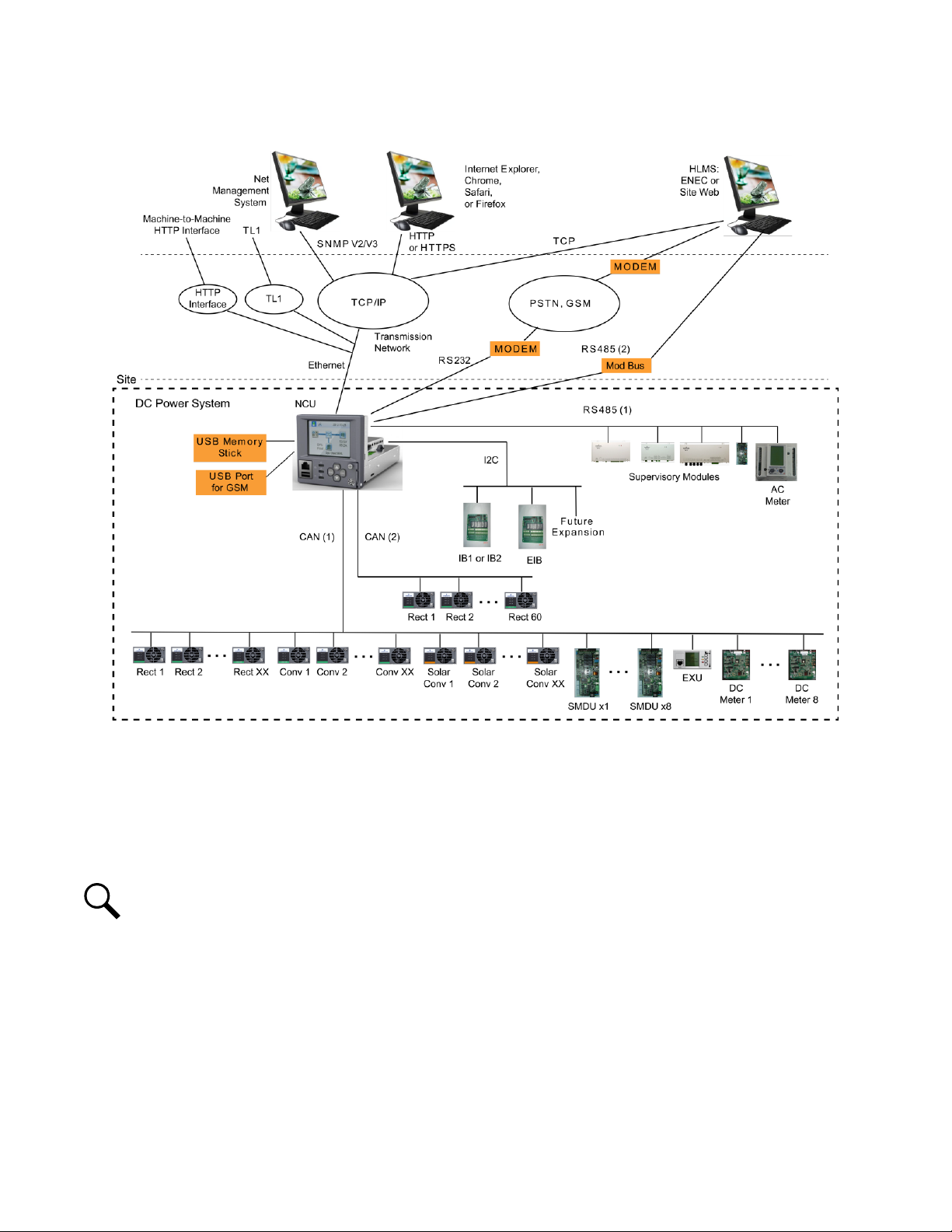
Figure 1-1 illustrates the various applications that can be used to interface with the NCU.
Page 12
Vertiv™ NetSure™ Control Unit (NCU) User Manual
2
Figure 1-1: Interfacing with the NCU
1.3 Function Descriptions
1.3.1 Rectifier, Solar Converter, and Converter Control
The NCU controls rectifiers, solar converters, and converters automatically.
1.3.2 System Components Monitoring and System Alarms Generation
The NCU monitors the components comprising the system (such as the rectifiers, solar converters, converters, and supervisory
modules) and generates alarms if a fault condition occurs. The NCU also maintains an alarm history log.
The available system alarms are programmed with an Alarm Severity Level. Each Alarm Severity Level has different visual/audible
alarm attributes. Available Alarm Severity Levels and their attributes are listed in Table 1-1.
The available system alarms can also be mapped to alarm relays (located on controller interface boards) that can be wired to external
alarm circuits.
NOTE!
Solar Mode has to be enabled for NCU control of solar converters (see “Enabling Solar Mode” on page 38).
Page 13

3
Table 1-1: Alarm Severity Levels
Vertiv™ NetSure™ Control Unit (NCU) User Manual
Alarm
Severity Levels
Critical Alarm (CR) ON -- ON
Major Alarm (MJ) ON -- ON
Minor Alarm (MN) OFF ON OFF
No Alarm (NA) OFF OFF OFF
Red
LED
Yellow
LED
Audible
Alarm Buzzer
• Alarm Status Setting: Indicates if the alarm is active or not active, and the severity level
if active. The available alarm status settings are as follows.
- Critical Alarm: The fault endangers the power systems continued function.
- Major Alarm: The fault reduces the power systems functionality.
- Minor Alarm: Special operating condition.
- No Alarm: The alarm is disabled and no alarm is given.
• The alarm indicator turns OFF if the fault(s) that triggered the alarm clears.
• The audible alarm can be silenced by pressing any key on the NCU local interface pad.
The audible alarm is also silenced if the fault(s) that triggered the alarm clears.
• An audible alarm cutoff feature can be programmed that silences the audible alarm after a
preset programmable time period. The audible alarm can also be disabled.
1.3.3 Operating Data Acquisition and Data Logs
The NCU acquires and analyses real time data from the system's components such as the rectifiers, converters, and supervisory
modules.
The NCU uses this data to process alarms and also records data in logs. The logs are viewed using the Web Interface and consists of
the following. Logs can be saved in the .html (Web page) or .txt (text) format.
Data History Log/Event Log/Alarm History Log: There is a maximum of 60,000 data points recorded between these logs.
• Alarm History Log: Records 4000 latest alarms. The Web Interface displays the latest 500 items.
• Battery Test Log: Up to ten (10) battery discharge tests can be recorded.
• Event Log: Records 4000 latest events. The Web Interface displays the latest 500 items.
• Data History Log: The Web Interface displays the latest 500 items, and you can upload a file with up to the latest 6,000
items in a single date range. Use multiple date ranges to upload more than 6,000 items.
• System Log: Records 3000 items in run log. The Web Interface displays the latest 500 items.
• Diesel Test Log: Records 500 latest diesel test results.
NOTE!
For all logs except the
Battery Test Log
, once maximum number of log entries is reached, new entries overwrite the
oldest entries.
1.3.4 Battery Management
The NCU provides the following battery management functions.
• Battery Charge Temperature Compensation
Page 14

Vertiv™ NetSure™ Control Unit (NCU) User Manual
4
• Battery Equalize Charge
• Battery Charge Current Limit
• High and Low Battery Temperature Alarms
• Battery Thermal Runaway Management (BTRM) Feature (Reduces Voltage during a High Battery Temperature Condition)
• Battery Discharge Test
• Battery Test Logs (maximum ten [10] tests saved)
• Battery LVD (Low Voltage Disconnect)
• Battery Capacity Prediction
• Battery Block and Battery Midpoint Monitoring
• Thermal Runway Detection and Management
NOTE!
Battery management functions are not available for NCU configurations that enable NCU capability to receive status
information sent from FIAMM SoNick (Sodium Nickel) batteries.
Battery Charge Temperature Compensation
The NCU can be programmed to automatically increase or decrease system output voltage to maintain battery float current as
battery temperature decreases or increases, respectively. Battery life can be extended when an optimum charge voltage to the
battery with respect to temperature is maintained. Temperature is monitored by a sensor mounted on the battery. See your power
system documentation for temperature sensor information. You can also set high and low compensation temperature alarms.
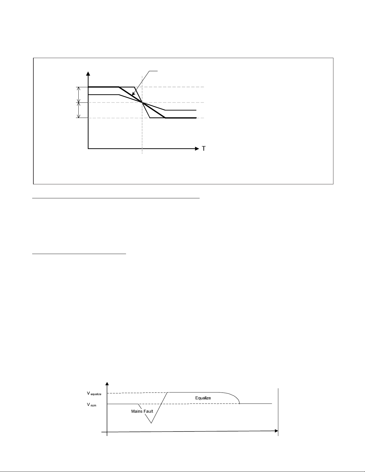
Functional Description (See Figure 1-2):
Battery charge temperature compensation adds a correction term, related to the temperature of the batteries, to the nominal value of
the system voltage. The degree of regulation (TempComp Coeff), expressed in mV/°C/battery string, can be set per battery
manufacturer recommendations.
To protect batteries and voltage-sensitive loads, compensation is automatically limited to a maximum of two volts (48V systems) or
one volt (24 volt systems) above or below the nominal output level (float setting). Temperature compensation can be set to clamp
lower than this by enabling the Temperature Compensation Clamp feature. When enabled, temperature compensation will clamp if
the battery temperature reaches either the Temp Comp Max Voltage setting or the Temp Comp Min Voltage setting.
Temperature compensation is automatically disabled if communication between the controller and all rectifiers is lost, a DC over or
under voltage alarm activates, a low voltage disconnection occurs, manual mode is entered, or the system enters the equalize or test
modes.
Refer to “Specifications” on page 259 for temperature probe and reading accuracy.
Page 15
5
Figure 1-2: Temperature Compensated Voltage Control
T
e
m
p
C
o
m
p
C
oe
ff
s
e
t
t
i
n
g
(
m
V
/
°
C
)
.
V
n
om
T
no
m
T
V
n
o
m
V
hi
gh
V
l
o
w
U
p
pe
r v
o
l
t
a
g
e
l
e
v
e
l
w
h
e
r
e
t
e
m
p
e
r
a
t
u
r
e
c
o
m
p
e
n
s
a
t
i
o
n
c
l
a
m
p
s
t
h
e
v
o
l
t
a
g
e
.
L
i
m
i
t
e
d
t
o
t
h
e
T
E
M
P
C
O
M
P
M
AX
V
se
t
ti
n
g.
N
o
mi
na
l
vo
lt
a
ge
(v
o
lt
ag
e
a
t
n
o
m
i
n
a
l
t
e
m
p
e
r
a
t
u
r
e
)
.
L
o
w
e
r
vo
l
ta
ge
l
ev
e
l w
he
r
e t
em
p
er
at
u
re
c
om
pe
n
sa
ti
o
n
c
l
a
m
p
s
t
h
e
v
o
l
t
a
g
e
.
L
i
m
i
t
e
d
t
o
t
h
e
T
E
M
P C
O
MP
MI
N
V
s
e
t
t
i
n
g
.
No
m
in
al
t
em
pe
r
at
ur
e
(n
o
t
e
m
p
e
r
a
t
u
r
e
c
o
m
p
e
n
s
a
t
i
o
n
i
s
d
o
n
e
a
t
t
h
i
s
t
em
pe
r
at
ur
e
).
Th
i
s
i
s
t
h
e
T
e
m
p C
o
m
p
s
e
tt
in
g.
1
V M
ax
(
24
V S
y
st
e
m)
2
V
Ma
x (
4
8V
Sy
s
te
m)
1
V M
a
x (
24
V
Sy
s
te
m)
2V
M
ax
(4
8
V S
ys
t
em
)
Vertiv™ NetSure™ Control Unit (NCU) User Manual
Battery Equalize Charge and Battery Charge Current Limit
The NCU can increase system output voltage for equalizing the charge on all battery cells of a conventional flooded cell battery, or for
recharging the battery following a commercial power failure.
The charging function can be initiated cyclically (scheduled), automatically, or manually.
Refer to the battery manufacturer's instructions for equalize charging instructions.
Functional Description (See Figure 1-3):
• Start of Charging: When the battery charge current exceeds a preset value for three (3) minutes or if the calculated battery
capacity has decreased to a preset value (after a commercial AC failure, for example), the charging function of the NCU is
activated. A charging signal is sent from the NCU to the rectifiers to increase the voltage up to the battery charging level
V
.
equalize
• Battery Current Limitation: After a commercial AC failure or when some battery cells are permanently damaged, the
current to the batteries can be quite extensive. To avoid overheating or further damages to the battery, the NCU limits the
battery current to a preset level by limiting the charging voltage of the rectifiers. Should the battery current still exceed a
higher preset value, an alarm is issued. Battery charge current is limited to the value set in the controller, as long as battery
voltage is above 47 VDC.
• End of Charging: When the charging current drops below a preset value, a defined prolonged charging time is started
before the charging is stopped and the voltage of the rectifiers return to the float charging level (V
equalized charging limit time that stops the charging after a preset time.
). For safety, there is an
nom
Figure 1-3: Voltage Characteristics on Commercial AC Failure and Automatic Equalize Charging
Page 16
Vertiv™ NetSure™ Control Unit (NCU) User Manual
6
High and Low Battery Temperature Alarms
The NCU can monitor battery temperature via a temperature sensor mounted on a battery cell. Values for high battery temperature
and low battery temperature alarms can then be programmed into the NCU.
Battery Thermal Runaway Management (BTRM) Feature
The Battery Thermal Runaway Management (BTRM) feature reduces voltage during a high battery temperature condition.
You can designate a temperature sensor as the BTRM sensor. The BTRM sensor has High 2 and High 1 BTRM temperature alarm
limits. If battery temperature exceeds the “BTRM Temp High 2” setting, system voltage is lowered to the BTRM voltage setting. This
feature can also be disabled.
Battery Discharge Test and Battery Test Logs
The NCU can perform battery discharge tests to check the condition of the battery(s). There are three (3) types of battery discharge
tests:
• Battery Test without Constant Current
• Battery Test with Constant Current
• Short Time Test (requires two battery shunts)
A User can manually start a battery discharge test or program the NCU to automatically start battery discharge tests at scheduled
intervals. Twelve (12) Constant Current Tests can be scheduled by the month-day-hour. A Short Time Test can be scheduled to be
performed every 1-365 days. During a battery discharge test, the NCU controls the rectifiers output to place the entire load or partial
load on the batteries. The NCU monitors the discharge of the battery and saves the results in a battery test log. The NCU stores ten
(10) battery discharge tests.
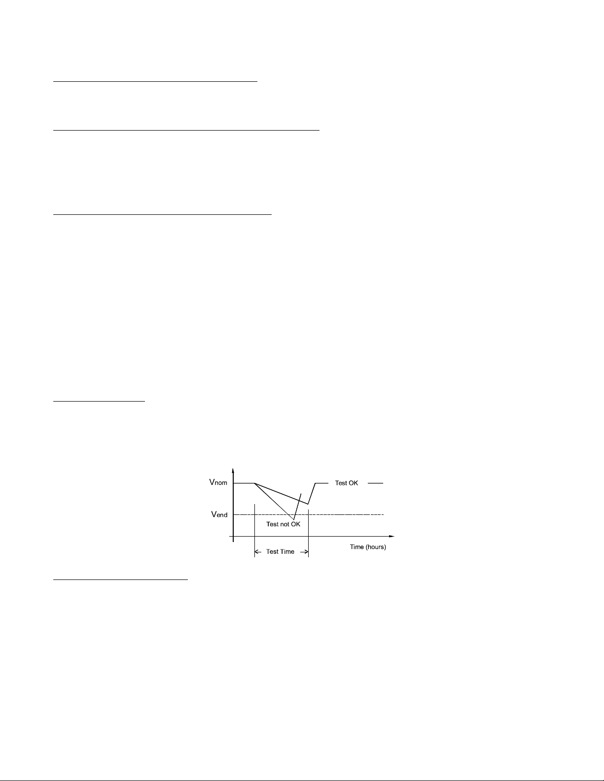
Functional Description:
For manual battery discharge tests as well as for scheduled battery discharge tests, the following parameters must be set: End Test
Voltage, End Test Time, and End Test Capacity. See Figure 1-4.
Figure 1-4: Battery Test Diagram
Battery Discharge Test Sequence:
• For a Constant Current Test, the output voltage of the rectifiers is reduced so that the batteries supply the preset Constant
Current Test Current to the load.
• If Constant Current is disabled, then the current being delivered by the batteries will be dependent on the load.
• For a Short Time Test, the output voltage of the rectifiers is reduced so that only the batteries power the load. If the batteries
fail, the rectifiers power the load.
• The battery test continues until one of the following occurs:
- The preset End Test Time, see Figure 1-4, expires. The battery has passed the test.
- The battery capacity drops below the preset End Test Capacity. The battery has passed the test.
Page 17

Vertiv™ NetSure™ Control Unit (NCU) User Manual
7
- The battery voltage drops below the preset End Test Voltage (Vend) (see Figure 1-4). The battery has not passed the
test and the test is interrupted. A bad battery alarm is activated.
- If a critical alarm occurs during the test or there’s not enough load, the battery test is aborted. In such cases a “Battery
Test Fail” alarm will be activated (indicating the test couldn’t be done). This alarm is different from the “Bad Battery”
alarm (meaning the test was completed but the battery didn’t pass it).
• A battery test alarm is active during a battery discharge test.
• If the battery has not passed the test, a bad battery alarm is activated.
• After the battery discharge test, the output voltage of the rectifiers increases so that the rectifiers supply the system and
charge the batteries.
NOTE!
A procedure for performing a manual battery discharge test is provided on page 47.
Battery LVD (Low Voltage Disconnect)
To prevent serious damage to the batteries during a commercial AC power failure, the batteries can be disconnected by voltage or
time control.
The batteries are reconnected automatically when commercial AC power is restored and a predetermined DC voltage level is reached.
See “LVD Tab Programmable Parameter Descriptions” on page 150 for descriptions of programmable LVD parameters.
Battery Capacity Prediction
The NCU can predict battery capacity. When a battery is connected to the system at initial setup or increasing the number of
batteries, you need to update the Battery Ah rating. After doing this and making sure the battery is fully charged you need to reset
the battery capacity used percentage by performing the “Reset Battery Capacity” command to tell the NCU that the batteries are
100% charged. From this point forward the NCU will keep track of the battery current and time to predict the battery capacity used.
Battery Block and Battery Midpoint Monitoring
The NCU can monitor battery blocks (12 V blocks) or midpoint battery voltage of battery strings connected to the EIB (Controller
Extended Interface Board) assembly. An alarm is issued when either battery block voltage or battery midpoint voltage is abnormal.
Thermal Runaway Detection and Management
Functional Description:
The system uses several control mechanisms to avoid thermal runaway.
• During a short high rate discharge, the batteries will normally get hot. The NCU takes this into consideration. After
completion of the discharge duty, the batteries are recharged with a limited current to avoid heating the batteries any further.
• The temperature of the batteries can be monitored, and the NCU sets the charge voltage appropriately, as previously
described under “Battery Charge Temperature Compensation” on page 4.
• In addition to battery temperature compensation, if battery temperature rises above a set temperature limit, the system stops
battery charging completely by lowering the output voltage to the “BTRM Voltage” setting. This allows the batteries to cool
down. The system also provides alarm notification of this occurrence. Power supplied to customer equipment is not
interrupted. See “Setting Battery Thermal Runaway Management (BTRM) Feature” on page 40 for programming.
• The battery LVD circuits can be programmed to open (disconnect) if a high temperature event occurs (HTD-High
Temperature Disconnect). The contactor(s) open when battery temperature rises above a programmable value and close
again when battery temperature falls below another programmable value. See “LVD Tab Programmable Parameter
Descriptions” on page 150 for programming.
Page 18

Vertiv™ NetSure™ Control Unit (NCU) User Manual
8
1.3.5 Energy Management
Energy Management consists of an Energy Optimization Mode.
Energy Optimization Mode
The NCU provides an Energy Optimization Mode (ECO) function. Energy Optimization permits an installation to only operate
rectifiers as needed to maintain the load and keep batteries in a fully charged condition. As load increases, Energy Optimization turns
on additional rectifiers as needed to maintain the load. As load decreases, Energy Optimization places rectifiers in standby to
conserve energy usage. Rectifiers which are always operating to maintain any load requirements are cycled through the group of
rectifiers controlled by this feature to provide uniform operating times for each rectifier.
ALERT! The Energy Optimization Mode should NOT be used in systems that operate without batteries.
The following operating conditions apply:
NOTE!
If the battery is ever disconnected, disable Energy Optimization Mode until the battery is reconnected.
1. The ECO mode is only enabled upon normal system operation. If any of the following alarms occurs, the system cannot enter
or will exit the ECO mode.
a) Current imbalance (only when imbalance current protection is enabled).
b) AC fail.
c) Any one rectifier over temp.
d) Any one rectifier AC fail.
e) Any one rectifier fault.
f) Any one rectifier over voltage.
g) Any one rectifier fan fault.
h) Any one rectifier no response.
i) Any one battery fuse open.
j) Any one LVD disconnect.
k) Battery is in charge or discharge, as defined below:
- Battery current > [battery rated capacity × 0.005], or battery current > 5A means battery in charge.
- Battery current < [battery rated capacity × -0.003], or battery current < -2A means battery in discharge.
l) Under voltage.
m) Any one rectifier in current limit mode.
2. The system load cannot exceed the system energy saving point (default value is 45%). Otherwise the system cannot enter or
will exit the ECO mode.
3. When the rectifier load exceeds its optimal operating point, the system will exit the ECO mode and the controller will
recalculate and then turn off any unnecessary rectifiers. After that, the system can enter the ECO mode again.
Page 19
Vertiv™ NetSure™ Control Unit (NCU) User Manual
9
4. If the system enters the ECO mode and then exits for five consecutive times within one hour, an abnormal alarm (ECO Cycle
Alarm) will be generated and the system can no longer enter the ECO mode until the ECO Cycle Alarm is cleared manually or
retires automatically after 24 hours.
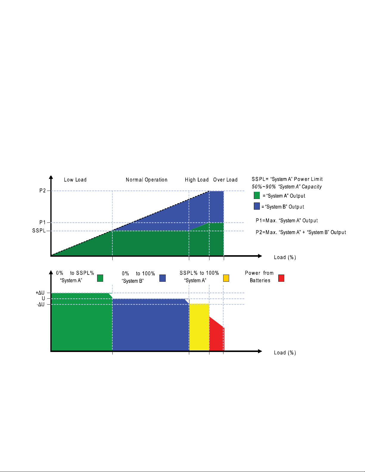
1.3.6 Power Split Feature
The Power Split feature allows you to connect the power system controlled via the NCU to an existing DC power system instead of
extending or completely replacing the existing DC power system.
The power system controlled via the NCU functions as “System A” to share load (split output) with the existing system (“System B”)
that requires expansion. The NCU does not require communication with the “System B’s” controller.
The Power Split feature provides for the sharing of total load in a controlled manner between the paralleled power systems.
When Power Split is programmed, the NCU adjusts rectifier output voltage per load demands to ensure proper sharing between
“System A” and “System B”. See Figure 1-5.
Figure 1-5: Power Split Feature
1.3.7 AC Generator Function
This is a special feature to control an AC generator using the NCU controller by either a voltage threshold or a battery capacity
threshold. The control occurs from a User designated relay located on the IB2 or EIB board. When this generator relay is activated,
this means the generator should turn “On”. Criteria for the generator function is to start the generator when either the output voltage
(AC Generator Start Voltage setting) or battery capacity (AC Generator Start Capacity setting) decreases to the set point. Once this
occurs, an alarm called “Automatic AC Generator Run” is activated, the relay changes state, and the generator is told to start. The
generator runs for a period of time and is then turned off after the Auto Equalize feature of the controller finishes.
Page 20

Vertiv™ NetSure™ Control Unit (NCU) User Manual
10
Auto Equalize looks for two (2) specific conditions for activation.
1. Has the recharge current (provided either by the rectifiers or solar converters) exceeded a User settable Equalize Start
Current value for three (3) minutes or
2. Has the battery capacity decreased to a User settable value.
If either of the above conditions are reached, Auto Equalize activates and the NCU controller tells the rectifiers and solar converters (if
present) to provide their respective output equalize voltages. Auto Equalize will deactivate once the battery recharge current reaches
the Equalize Stop current level and the Equalize Stop Delay has been satisfied. Once equalize has finished, the generator will also
shut off if it is running.
In addition to the automatic features above, this Generator Function will provide a way to manually run the generator when necessary.
Although not necessary for operation, the function will also have the capability for recognizing a digital input signal that can be used
to send feedback to the controller that the generator is running.
See “AC Generator Function:” starting on page 143.
1.3.8 Diesel Management Feature
The Diesel Management feature is available when an SM-AC supervisory module is connected to the NCU. The Diesel Management
feature consists of a Diesel Test. The Diesel Test can be performed at specific intervals or a User can manually start the Diesel Test.
The NCU records the test results.
1.3.9 Hybrid Control Function (Supporting Generator, Solar and Wind Energy Input, and
Optimization)
Hybrid Control is designed for use in new installations or as an upgrade of existing sites powered by a diesel generator(s) when grid
power is not available. The Hybrid control is also applicable to sites with highly unreliable or frequently unavailable grid power
connection. The primary power source is still considered to be the diesel generator(s). Since grid power is always given priority, the
primary power source is still considered to be the grid power.
General
Hybrid Control allows the option of selecting one of the following: Fixed Daily Time based operation or Capacity Discharge based
operation.
Fixed Daily Time based operation is intended to be used with a combination of AC powered active cooling (air conditioners) and DC
powered cooling (heat exchangers, etc.). The cycle period is synchronized to the 24hrs day-night cycle. It makes optimum use of the
different temperature conditions during the day and the night in order to facilitate Hybrid fuel saving operation.
Capacity Discharge based operation is intended for sites utilizing only DC powered cooling (heat exchangers, etc.). The cycle period
is determined by User selectable depth of discharge (DOD) of the batteries per cycle, and associated recharge time. It provides
optimum Hybrid fuel saving operation.
Operation from Grid Power is performed with both Fixed Daily Time and Capacity Discharge modes of operation. Grid power is
always given priority when available.
NOTE!
The Hybrid Control function requires a specific configuration. Hybrid Control menus will not normally be displayed
unless your NCU has been configured by Vertiv for this function. Contact Vertiv for a Hybrid Control configuration.
As the two types of control are specific to the hardware configuration of the site, the Fixed Daily Time or Capacity Discharge is a User
selectable option on installation.
Page 21

Vertiv™ NetSure™ Control Unit (NCU) User Manual
11
Hybrid Operation
Generator Control: A potential free relay contact output from the NCU interface board controls the start and stop of the diesel
generator. The signal will be generated by the NCU and operates according to the Hybrid software mode of operation. The default
control logic (User selectable) is as follows:
• Energized Output Relay - Generator OFF
• De-energized Output Relay – Generator ON
This is a fail-safe logic to ensure generator operation in all cases where power or control to the relays is lost.
In addition, the type of signal to the Generator can be selected as N/O (Normally Open) or N/C (Normally Closed) by selecting the
relevant output pins of the control relay.
Number of Generator Control Outputs: The NCU Hybrid software can control one or two generators. Each generator control is
designated as DG1 or DG2 output. The User can select DG1, or DG2, or DG1 and DG2. When both are selected they will be
alternatively used (two generators operation).
Diesel Fail Alarm: A diesel fail alarm will be generated if the Diesel Generator ON signal fails to bring the generator to operation and
provide the system with AC power. Alarm will be triggered after 60 seconds (default value, settable) from ON signal. If two generator
operation is selected, the second Diesel Generator ON signal will be activated simultaneously with the Diesel Fail alarm.
Battery Fuse Trip Alarm: In the event of a Battery Fuse trip condition, an alarm will be generated.
Under Voltage Alarms:
• Under Voltage Alarm 1: If voltage decreases below the Under Voltage Alarm 1 setting, an alarm is raised.
• Under Voltage Alarm 2: If voltage decreases below the Under Voltage Alarm 2 setting, the Diesel Generator is started and
an alarm is raised.
LVD 1: Normal loads are disconnected.
LVD 2: Priority loads are disconnected.
Charge Voltage: Refer to Figure 1-6.
Equalize Charge: The battery will be recharged at the equalize voltage. This is the voltage set in the initial phase of battery
recharge. See Figure 1-6.
As the voltage limit is reached, the charge current is gradually reduced – this effect is known as current tail. When the current tail falls
below a threshold level, additional equalize charge time is added and then the recharge ends.
The equalize charge current tail threshold is settable from 0.002 to 0.02. Default setting is 0.01 (1 A per 100 Ah). The additional
equalize charge time is settable from 1 hour to 24 hours (settable in minutes from 0 to 1440), default setting is 3 hours. The duration
of the equalize charge is the time from the start of the recharge to the end of the additional time. (Maximum charge time, determined
from the time charge starts, is settable in the range of 1 hour to 48 hours, default setting is 18 hours).
The end of recharge is determined by a three (3) step approach:
• Step1 - calculated battery capacity exceeds 90%. Calculation is performed by measurement of battery current and time, in
Ah.
• Step 2 - charge current tail threshold is reached.
• Step 3 - additional charge time is completed.
Page 22
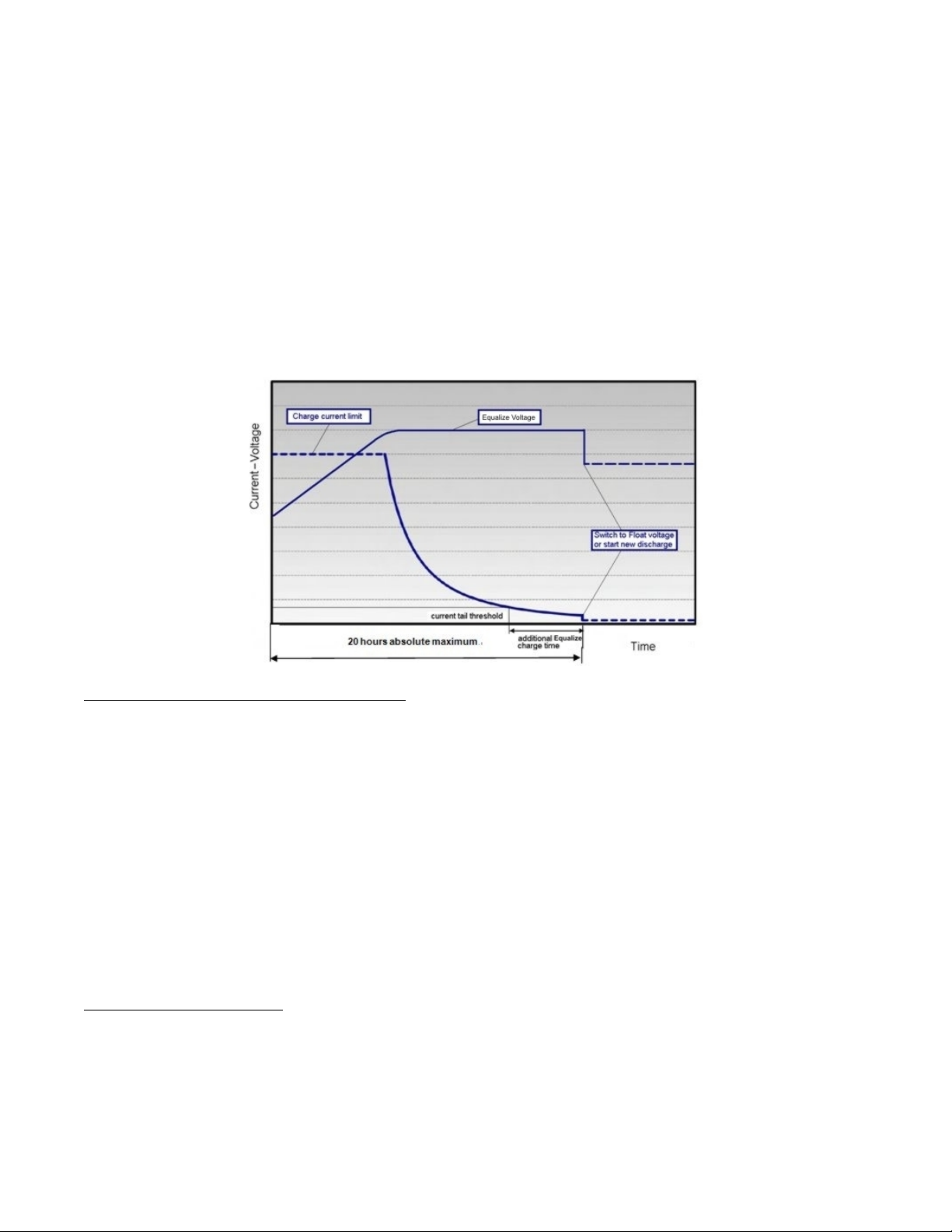
Vertiv™ NetSure™ Control Unit (NCU) User Manual
12
Float Charge: Default float voltage is 54.0 V at 20°C with a temperature compensation of 72 mV per °C.
If battery temperature exceeds the BTRM Temp High 2 alarm set point, the charge voltage is reduced to 48 V to reduce gassing and
prevent thermal runaway. The same is applicable as well for equalizing charge.
Equalizing Charge Cycle: As the cyclic use does not ensure complete battery recharge after every cycle, an equalizing charge cycle
is added. The equalizing cycle is settable for every 2 to 365 days intervals, default setting is 100 days. Equalizing charge time is 12
hours independent of discharge time setting. Equalizing charge is performed at equalize voltage until end of additional equalize time
and thereafter at float voltage for the remaining time. Also see Figure 1-6.
Equalize charge independently settable 0-1440 min (already set in equalize charge).
Figure 1-6: Charge Voltage
Early Termination of the Discharge Periods
During discharge, over temperature and under voltage conditions will interrupt the discharge and change the operation to
charge with the Diesel Generator ON.
Over Temperature: The diesel generator will start and run for a period before it is stopped again. The run time is User selectable in
the range 30 to 120 minutes, default setting is 60 minutes. Temperature is referenced to cabinet/shelter ambient temperature sensor
connected to controller, not battery temperature. Over temperature start can be disabled completely from the Settings menu.
Under Voltage: The under voltage start is triggered by under voltage alarm 2 voltage settings.
The diesel generator will start and run until the normal recharge cycle is due to finish depending on selected mode of operation.
Under Voltage with Fixed Daily Time: If the normal recharge cycle is from 7am until 7pm and under voltage has started the Diesel
Generator at 5:30am, the effective recharge will be from 5:30am until 7pm.
Under Voltage with Capacity Discharge: If this mode is selected, the recharge will terminate.
Operation with Grid Power
Grid power is always used when available. If grid power becomes available during battery discharge, the discharge cycle is terminated
and recharge cycle is initiated. If grid power becomes available during diesel generator operation, the diesel generator is switched
OFF and operations continue on grid power.
Battery Recharge with Grid Power: Battery recharge with grid power can start from the beginning (when grid power becomes
available during battery discharge) or can continue from diesel generator recharge, depending on the timing. In both cases, the
Page 23

Vertiv™ NetSure™ Control Unit (NCU) User Manual
13
recharge process will follow the recharge profile shown in Figure 1-6. If battery becomes fully recharged and grid power is still
present, the operations will continue to be powered from grid and no battery discharge will be initiated for the duration of grid
availability. In this case, battery voltage will revert back to Float voltage.
Battery Discharge after Grid Failure: At the point of grid power failure, the battery capacity is unknown as these events occur in
random manner. For the purpose of maximizing the use of grid power and in anticipation of grid power becoming available again, the
Hybrid operation will continue with battery discharge cycle. Discharge will continue until:
• The preset discharge time elapses (Fixed Daily Time)
• The preset DOD is reached (Capacity Discharge)
In both cases, the discharge can be terminated earlier as described in “Early Termination of the Discharge Periods” on page 12.
Relay Assignment – when in Hybrid Mode
Relay 1: Generator Alarm.
No Generator Voltage Alarm. No AC supply, 60 sec delay.
Relay 2: Battery Alarms.
Logic alarm generated from: under voltage 1, under voltage 2, LVD1, LVD2, battery high temp, battery very high temp, overvoltage 1,
overvoltage 2, battery temp sensor fail, battery fuse alarms and high load alarm.
Relay 3: Rectifier Alarms.
Logic alarm generated from: multiple rectifier fail, rectifier fail, rectifier fan failure, rectifier HVSD, rectifier AC failure and rectifier not
responding.
Relay 4: System Alarms.
Logic alarm generated from: load fuse alarms, high ambient temperature, ambient temp sensor fail; smoke detected, and water
detection.
Relay 5: Generator Run at High Temp.
Output to intelligent cooling devices linked to AC supply (DG run).
Relay 6: Intruder Alarm.
Alarm triggered by dry contact door/motion sensor.
Relay 7: Diesel 1 in Operation.
Output to DG1 on site. DG is set on for the duration of the signal.
Relay 8: Diesel 2 in operation.
Output to DG2 on site. DG is set on for the duration of the signal.
Fixed Daily
In this mode of operation, the total duration of a complete cycle is 24hrs. This duration is necessary as the operation is synchronized
with day-night temperature pattern. When an extended recharge cycle is required, its termination will still follow the 24hrs schedule.
Cycle Duration: A complete cycle consists of discharge and charge periods during the combined total of 24hrs. The discharge
period starts at 7pm. It is then followed by recharge period (Diesel Generator ON) for the remainder of the 24hrs. The discharge time
is User selectable in the range 1hrs to 22hrs, default setting is 12hrs.
Discharge: The discharge start time and duration are settable. Discharge period starts at 7pm. The discharge time is User
selectable in the range 1hours to 22hours, default setting is 12 hours.
Recharge: Recharge period (Diesel Generator ON) follows after discharge for the remainder of the 24hrs. Recharge is performed at
equalize voltage until added equalize time elapses and at float voltage for the remaining charge time.
Page 24

Vertiv™ NetSure™ Control Unit (NCU) User Manual
14
High Load Alarm: In order to identify conditions where the load requirements are exceeding the dimensioning of the Hybrid site, an
alarm will be generated. The alarm will be triggered when the maximum capacity per discharge cycle is exceeded. The threshold
value will be set as default to 40% of battery capacity. It will require capacity measurement per cycle. The alarm will be set once the
high load threshold value is reached and is reset at the beginning of the next discharge period. This alarm will help the User identify
the root cause of the under voltage condition: high demand load, the loss of capacity due to battery aging, or insufficient charge
capacity.
Capacity Discharge
The cycle period is determined by User selectable capacity discharge of the batteries and associated recharge times. The cycle
repeats continuously. It does not follow a 24hrs pattern.
Capacity Discharge and Recharge: The battery discharge period is determined by the percentage of the nominal battery capacity
[Ah] that will be discharged per cycle.
The depth of discharge [DOD] per cycle is User selectable in the range 20% to 80%. Default setting is 60%. The value is set as
battery capacity at the end of each discharge period. Therefore, if a 60% discharge is chosen, the discharge value is set to 40%.
The time to recharge to full battery capacity depends on battery capacity at the start of the charge cycle and the available recharge
current.
When the additional charge time has been reached; the generator will be stopped, the recharge cycle will end, and discharge cycle will
be initiated.
For practical purposes, the battery capacity at the end of every recharge period is set to 100% as long as Step1, Step 2, and Step 3
have elapsed.
If end of charge is not reached within the set maximum hours, the recharge will be terminated and discharge cycle will be initiated.
1.3.10 Supervisory Module (SM Modules) Monitoring
Various devices (supervisory modules) can be connected to the NCU to extend its monitoring capabilities.
1.3.11 Maximum Current Limit Function
The current available from the rectifiers can be limited (in AMPS) from 10% to 121% of combined rectifier capacity. The factory setting
is 121% unless otherwise specified. The current available from the converters can be programmed (in AMPS) from 50% to 116% of
combined converter capacity. The factory setting is 116% unless otherwise specified. Refer to the NCU Configuration Drawing (C–
drawing) supplied with your system documentation for your system’s settings.
See also “Checking the Controller’s Current Limit Point after Adding or Removing a Rectifier or Converter Module” on page 37.
1.3.12 Communications Function
The NCU is able to communicate with different equipment or, connect to different equipment for communication. See Figure 1-7.
a) 10M/100M Ethernet Port: The NCU can communicate with a supervisory computer or other devices through its 10M/100M
Ethernet port. The communication cable shall be a shielded cable. The Ethernet port is located on the front panel of the
NCU. This port supports Dynamic Host Configuration Protocol (DHCP) function.
NOTE!
Some systems may have an IB4 board with a second Ethernet port. The IB4 board is connected to the NCU’s
backplane connector (USB) via a factory provided cable. Refer to your system’s documentation for location of the IB4 board
(if furnished).
b) IB2 (Interface Board) and EIB (Extended Interface Board): Some systems may have an IB2 (Interface Board) and/or EIB
(Extended Interface Board) connected to the NCU. Each IB2 board provides eight (8) dry relay outputs. Each EIB board
provides five (5) dry relay outputs. Every relay output has a set of NC (normally close) and NO (normally open) contacts.
Page 25
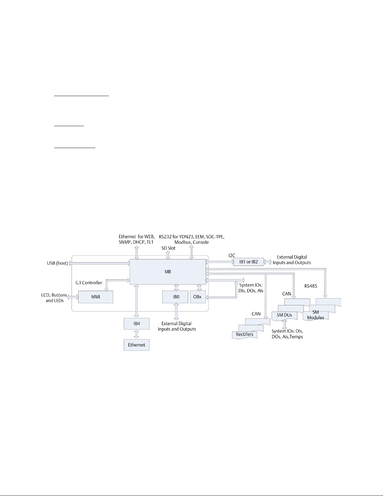
Vertiv™ NetSure™ Control Unit (NCU) User Manual
15
The relay outputs can be connected to customer external alarm circuits. Each relay output can be configured to change
state when one or more alarm events occur.
The relay outputs can also be connected to customer external equipment, so that the relay output can control or interface
with the customer external equipment.
c) IB4 (Interface Board 4): Some systems may have an IB4 board. The IB4 board is a USB to LAN converter for the NCU, which
includes a USB and an Ethernet port. The IB4 board is connected to the NCU’s backplane connector (USB) via a factory
provided cable. Refer to your system’s documentation for location of the IB4 board (if furnished).
d) RS-485 Port: The NCU can communicate with an SM-AC, SM-Bat, or SMIO through the RS-485 port. The RS-485 port uses
the parameters 19200, n, 8, 1.
e) Modbus Protocol: The NCU can communicate with an AC Meter using the Modbus protocol.
f) TL1: See “TL1 Interface” starting on page 59.
g) Machine-to-Machine HTTP Interface: See “Machine-to-Machine HTTP Interface” starting on page 60.
1.3.13 FIAMM SoNick (Sodium Nickel) battery Interface
If a special configuration file is furnished, the NCU has capability to receive status information sent from FIAMM SoNick (Sodium
Nickel) batteries. See “FIAMM SoNick (Sodium Nickel) Batteries Interface” starting on page 57.
Figure 1-7: The Controller Perspective
1.3.14 Radius Server Feature
When the radius server feature is enabled and a User attempts to login using the LCD or web page, the NCU first checks the
username/password entered for a match programmed in the NCU. If the NCU authenticates, then the NCU grants the User access.
This step is to allow a login in case the radius server is not available, has changed, etc.
If the authentication fails (either not present or wrong password), then the NCU checks the username/password entered using the
radius interface. If the NCU authenticates, then the NCU grants the User access. If authentication fails, the NCU notifies the User and
does not grant the User access.
If an IB4 board is present, the radius messages are sent to the IB4 network interface; otherwise, the radius messages are sent to the
front (craft) port.
Page 26

Vertiv™ NetSure™ Control Unit (NCU) User Manual
16
The NCU sends the Service-Type attribute. The Service-Type attributes supported are:
1 Login – browser privilege level.
5 Outbound – operator privilege level.
6 Administrative – admin privilege level.
7 NAS Prompt – engineer privilege level.
If the server responds with an unknown Service-Type, the NCU will record the event it in the system log and act as though access was
rejected, per RFC 2865.
The NCU does not support the Access-Challenge response from the server. If this response is received, it is ignored.
The radius server settings are programmed using the web interface. Admin privilege level access is required.
Page 27
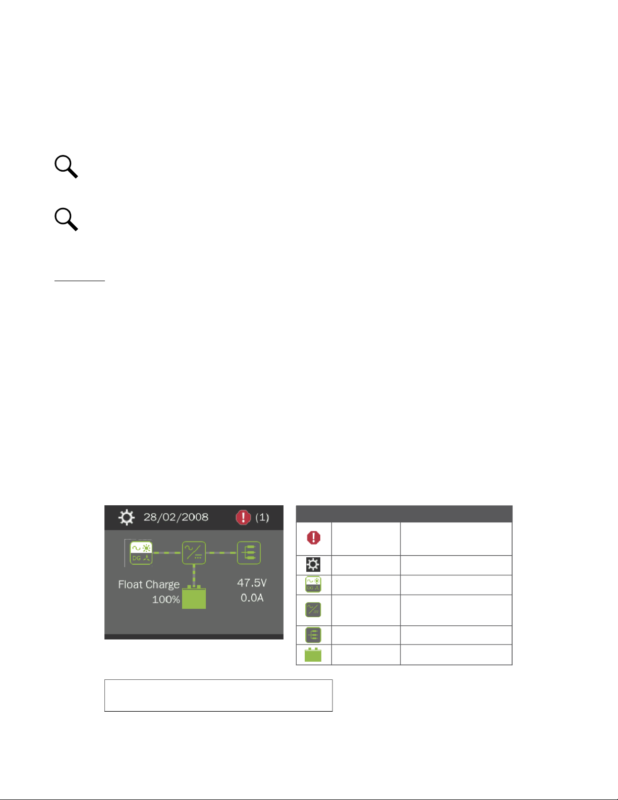
Vertiv™ NetSure™ Control Unit (NCU) User Manual
17
Graphics Menu Name Description
Alarm
(Green - No Alarm)
(Red - Alarm)
View active alarms and
alarm history.
Settings
Gain access to the NCU
Controller’s settings menus.
Input Power
View AC, Solar, DG, and
Wind related information.
Module
View rectifier, solar converter,
and converter module
related information.
DC
View DC equipments
related information.
Battery
View battery related
information.
To reboot the Controller, from the Main Menu press the ENT and ESC
keys at the same time. Release both keys. Press ENT to confirm.
Date and time are
alternately displayed.
Green - No Alarm
Red - Alarm
Main Menu
Rect Cap Used: 22.3 %
The number in ( ) indicates
the total number of alarms.
Press the UP and DOWN keys to highlight
the desired Menu graphic in the Main Menu.
Press the ENT key to enter the selected menu.
2 Operation
2.1 Controller Initialization
The controller goes through an initialization process when power is initially applied to the system.
NOTE!
The initialization routine takes several minutes. During that time various alarm indicators may illuminate on the
controller’s front panel and an audible alarm may sound. Disregard all alarms. An audible alarm can be silenced at any time
by momentarily depressing the ENT key on the controller.
NOTE!
The controller does not turn off any relay when the controller is reset/replaced. If the relay is active when the
controller is reset/replaced, it will stay active whether or not the alarm condition still exists. If possible, the alarm condition
should be cleared before the controller is reset/replaced. If the alarm is not cleared, after starting the controller, it may be
necessary to manually trigger an alarm condition to clear all alarm relays.
Initialization
1. After the controller is powered on, the display shows the “logo” screen. The controller is initializing.
2. When initialization is complete, the language screen appears. Press the UP or DOWN arrow key to select the desired
language. Press the ENT key to confirm the selection.
3. The following message appears.
“Please go to webpage to change the factory default password. Press enter to continue.”
This message will appear every time the controller is rebooted until the factory default password is changed. See “Logging
into the Controller via Web Interface Access” on page 29.
4. The Main Menu displays. See Figure 2-1.
Figure 2-1: NCU Local Display Main Menu
Page 28
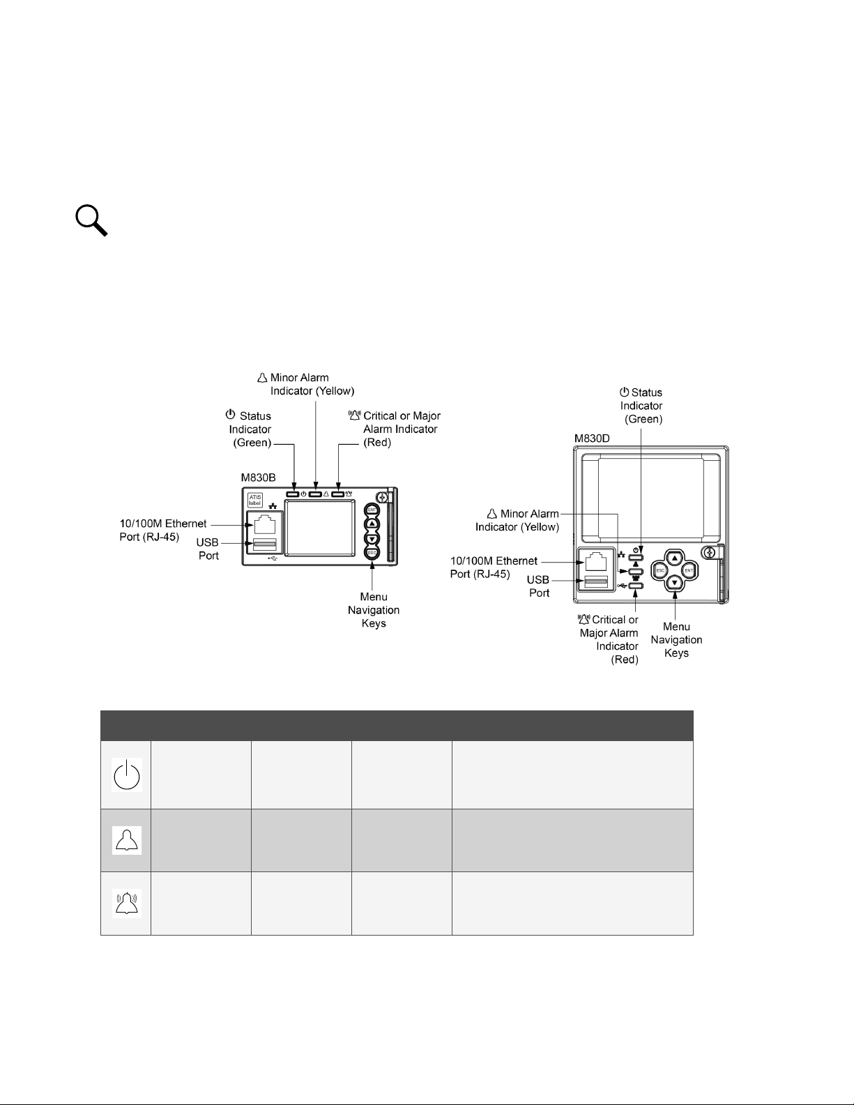
Vertiv™ NetSure™ Control Unit (NCU) User Manual
18
5. System information is displayed in multiple screens. Press the ESC key to view other system information. Press the down
arrow key to view the next screen. Press the ESC key to return to the Main Menu.
6. From the Main Menu, press the UP and DOWN keys to highlight the desired Menu graphic in the Main Menu. Press the ENT
key to enter the selected menu.
NOTE!
Repeatedly press the “ESC” key to return in reverse order level by level from any submenu until the Main Menu
appears.
2.2 Local Indicators
There are three (3) indicators located on the NCU’s front panel. Refer to Table 2-1 for the function of the indicators. Refer to Figure
2-2 for location.
Figure 2-2: Local Indicators and Menu Navigation Keys Locations
Table 2-1: Local Indicators
Indicator Normal State Fault State Fault Cause
Status
(Green)
Minor Alarm
(Yellow)
Major or Critical
Alarm (Red)
On Off No input power to the NCU.
Off On
The system has one or more active Minor
alarms. Alarm conditions are programmable.
The system has one or more active Major or
Off On
Critical alarms. Alarm conditions are
programmable.
Page 29

Vertiv™ NetSure™ Control Unit (NCU) User Manual
19
2.3 Using the Local Keypad and Display
See also “Passwords and Privilege Levels” on page 20.
2.3.1 Local Menu Navigation Keys and Local Display
There are four (4) menu navigation keys and a local display located on the NCU’s front panel. Refer to Table 2-2 for the function of
the menu navigation keys. Refer to Figure 2-2 for location.
Table 2-2: Local Menu Navigation Keys
NOTE!
When the local display is lit, if no button is pushed for eight (8) minutes, the backlight of the local display extinguishes
and the NCU returns to the Main Menu. Press any key to re-activate the local display.
Key Symbol Key Name Function
ESC Escape
ENT Enter
Press any key to silence an audible alarm.
Up Arrow
Down Arrow
Press this key to go back to a previous menu or to cancel
setting a parameter.
Press this key to go forward to the next menu, to select a
parameter to edit, or to validate a parameter setting change.
Press the up or down arrow keys to scroll through the menus
or to change the value of a parameter.
2.3.2 Local Display Menus
Refer to “Local Display Menus” on page 85.
Navigating the Menus
To Select a Sub-Menu:
Press the UP and DOWN keys to highlight the desired sub-menu.
Press the ENT key to enter the selected sub-menu.
Press ESC and ENT together to reset the NCU,
then press ENT to accept or ESC to cancel.
--
To Select a User and Enter a Password:
To select a User, use the UP and DOWN keys to move the cursor to the Select User field. Press ENT. Use the UP and DOWN keys to
select a User previously programmed into the NCU. Press ENT to select the User. Note that only Users programmed into the NCU
are shown. Users are programmed via the Web Interface.
To enter a password, use the UP and DOWN keys to move the cursor to the Enter Password field. Press ENT. Use the UP and DOWN
keys to choose a character. Press ENT to accept and move to the next character. Continue this process until all characters are
entered. Press ENT again to accept the password.
To Change a Parameter:
Press the UP and DOWN keys to move up and down the list of parameters.
Press ENT to select the parameter.
Press the UP and DOWN keys to change the parameter.
Press ENT to make the change. Press ESC to cancel the change.
Page 30

Vertiv™ NetSure™ Control Unit (NCU) User Manual
20
2.4 Using the Web Interface
See also “Passwords and Privilege Levels” on page 20.
NOTE!
The NCU supports a 10/100M Ethernet connection.
2.4.1 Overview
Via the Web Interface, a User (with proper access level) can:
• View real-time operating information (rectifiers, converters, solar converters, AC, DC, batteries, etc.).
• View and download information recorded in logs.
• Send control commands.
• Set programmable parameters.
• Download and upload the “SettingParam.tar” file.
• Download firmware to the controller.
2.4.2 Multiple Browsers Supported
Multiple browsers are supported in the Web Interface. The User can use Internet Explorer, Chrome, Safari, or Firefox.
2.4.3 Web Interface Screens
Refer to “Web Interface Screens” on page 110.
2.5 Passwords and Privilege Levels
Local Keypad and Display
Anyone can browse the NCU via the local keypad and display. A User Name and Password is required to change settings. User
Names and associated passwords are programmed into the NCU via the Web Interface. To change settings locally, a User Name and
Password for a User with an access level of Level B (Operator) or higher is required. See “Users Tab” on page 171. Once a password is
entered locally, it remains in effect for a preset time period to allow navigating between menus without re-entering the password.
Web Interface
Web interface access always requires a User name and password to be entered to gain access.
Web Interface User Privilege Levels: Users are programmed with a “privilege level” (see Table 5-1 on page 173). Each privilege
level gives a User Web access to specific menus, as shown in Table 5-2 on page 173. A User has access to his/her level menus, plus
all menus of the lesser privilege levels.
2.6 Multiple Languages Supported
Multiple languages are supported in the Local Interface and Web Interface. Refer to “Language Tab” on page 184.
2.7 Setup Procedures
2.7.1 Setting IPv4 Communications Parameters (if controller not set as DHCP)
The controller’s IPv4 parameters (IP, subnet mask, and gateway addresses) must be set to match your company’s network settings.
The default settings for these parameters are shown below.
Page 31

Vertiv™ NetSure™ Control Unit (NCU) User Manual
21
• IP Address: 192.168.1.2
• Subnet Mask Address: 255.255.255.0
• Gateway Address: 192.168.1.1
Local Menu Navigation:
Main Menu / Settings Icon / Comm Settings / enter parameters.
Web Menu Navigation:
Advance Settings Menu / Ethernet Tab / enter parameters.
2.7.2 Setting IPv6 Communications Parameters (if controller not set as DHCPv6)
The controller’s IPv6 parameters (IPv6 address, IPv6 prefix, and IPv6 gateway address) must be set to match your company’s network
settings. The default settings for these parameters are shown below.
• Link-Local Address: fe80:209:f5ff:fe09:1002/64
• IPv6 Address: 20fa:fffd:fffc:fffb:fffa:fff9:fff8:fff7
• IPv6 Prefix: 0
• IPv6 Gateway: 20fa:1:fffe:ffff:fffe:fffd:ffff:fffe
Local Menu Navigation:
Main Menu / Settings Icon / Comm Settings / enter parameters.
Web Menu Navigation:
Advance Settings Menu / Ethernet Tab / enter parameters.
2.7.3 Setting for DHCP and DHCPv6
The DHCP and DHCPv6 functions allow the controller to acquire an IP address automatically. This function can only be enabled or
disabled via the local display and keypad. If this function is enabled and the acquisition of an IP address fails, an alarm is generated. If
the acquisition of an IP address is successful, you need to record the IP address automatically acquired by the controller to access the
controller via the Web Interface. This IP address is displayed on the main system info screen (Main Menu / ESC) in the IP Address
field or in the local display menu (Main Menu / Settings Icon / Comm Settings) in the IP Address field below the DHCP setting.
Local Menu Navigation:
Main Menu / Settings Icon / Comm Settings / DHCP (set to enabled) (can also view acquired IP address).
Main Menu / ESC (to view acquired IP address).
Web Menu Navigation:
None.
2.7.4 Connecting the Controller to your Local Area Network (LAN) when the System is
NOT Equipped with an IB4 Board
An Ethernet port is located on the front panel of the NCU. This port supports Dynamic Host Configuration Protocol (DHCP) function.
If your system does not have an IB4 board, connect the Local Area Network (LAN) to the NCU’s front panel port. This port can be
assigned an IP address or can be set for DHCP. If set for DHCP, it will get its IP address from a DHCP server on the network. Refer to
“Setting IPv4 Communications Parameters (if controller not set as DHCP)” on page 20 or “Setting IPv6 Communications Parameters
(if controller not set as DHCPv6)” on page 21 to set the port parameters;
Page 32

Vertiv™ NetSure™ Control Unit (NCU) User Manual
22
or,
“Setting for DHCP and DHCPv6” on page 21 to set the port as DHCP or DHCPv6.
2.7.5 Connecting the Controller to your Local Area Network (LAN) when the System IS
Equipped with an IB4 Board
Some systems may have an IB4 board with a second Ethernet port. This port supports Dynamic Host Configuration Protocol (DHCP)
function. Refer to your system’s documentation for location of the IB4 board (if furnished).
If your system has an IB4 board, connect the Local Area Network (LAN) to the IB4 board port. The IB4 board port can be assigned an
IP address or can be set for DHCP. If it is set for DHCP, it will get its IP address from a DHCP server on the network. Refer to “Setting
IPv4 Communications Parameters (if controller not set as DHCP)” on page 20 or “Setting IPv6 Communications Parameters (if
controller not set as DHCPv6)” on page 21 to set the port parameters;
or,
“Setting for DHCP and DHCPv6” on page 21 to set the port as DHCP or DHCPv6.
NOTE!
Your system may be furnished with an IB4 board. The IB4 board provides a second Ethernet port. The Ethernet port
located on the NCU Controller’s front panel can ONLY be used to connect a computer directly to the NCU. The Ethernet port
located on the IB4 board can be used to connect the NCU to your Local Area Network (LAN). Refer to your system’s
documentation for location of the IB4 board (if furnished).
NOTE!
If your system has an IB4 board, DO NOT connect your Local Area Network (LAN) to the NCU front Ethernet port.
2.7.6 Connecting a Local Computer Directly to the Controller when the System is NOT
Equipped with an IB4 Board
An Ethernet port is located on the front panel of the NCU. This port supports Dynamic Host Configuration Protocol (DHCP) function.
If your system does not have an IB4 board, perform the following procedure.
Procedure
1. Before connecting your computer directly to the controller’s Ethernet port, use the following procedure to record your
computer’s network settings (so they can be returned to these values when done) and then change these settings in your
computer to match the communications settings programmed in the controller.
NOTE!
Windows 7 operating system is used in this procedure, other operating systems are similar.
a) Record your computer’s network settings by launching Control Panel in your computer. Navigate through Network and
Sharing Center Local Area Connection Properties Internet Protocol Version 4 (TCP/IPV4) Properties.
b) Record whether the "Obtain an IP address automatically" or "Use the following IP address" button is selected. If "Use the
following IP address" button is selected, also record the following:
IP Address:
Subnet Mask:
Default Gateway:
c) Record your controller’s network settings by navigating the controller’s local display panel to Main Menu / Settings Icon /
Comm Settings. Record the following controller’s IP parameters. If these parameters were not changed, they should be
at the default values as shown in the example section below.
IPv4
IP Address:
Page 33

Vertiv™ NetSure™ Control Unit (NCU) User Manual
23
Subnet Mask:
Default Gateway:
Example:
IP Address: 192.168.1.2
Subnet Mask: 255.255.255.0
Default Gateway: 192.168.1.1
IPv6
IPv6 Address:
IPv6 Prefix:
IPv6 Gateway:
Example:
IPv6 Address: 20fa:fffd:fffc:fffb:fffa:fff9:fff8:fff7
IPv6 Prefix: 0
IPv6 Gateway: 20fa:1:fffe:ffff:fffe:fffd:ffff:fffe
d) Change your local computer’s network settings using the information you acquired in the above step, except that the
last part of the IP address needs to be replaced with any different number.
IPv4
IP Address:
Subnet Mask:
Default Gateway:
Example:
IP Address: 192.168.1.3
Subnet Mask: 255.255.255.0
Default Gateway: 192.168.1.1
IPv6
IPv6 Address:
IPv6 Prefix:
IPv6 Gateway:
Example:
IPv6 Address: 20fa:fffd:fffc:fffb:fffa:fff9:fff8:fff7
IPv6 Prefix: 0
IPv6 Gateway: 20fa:1:fffe:ffff:fffe:fffd:ffff:fffe
e) Select OK. Note that you may have to reboot your local computer for the settings to take effect. Follow any instruction
you see on the screen.
2. Connect your computer directly to the controller’s Ethernet port (RJ-45 jack located on the front of the controller). See
Figure 2-2. The NCU’s front panel port is configured with an IP address. Default is 192.168.1.2. This is the address you will
type into your Web browser to access the NCU’s Web Interface. You will also have to set the properties on your computer
(refer to the previous procedure in step 1).
3. When finished, disconnect your computer from the NCU and, if necessary, reset your computer network settings as recorded
in step 1.
Page 34

Vertiv™ NetSure™ Control Unit (NCU) User Manual
24
2.7.7 Connecting a Local Computer Directly to the Controller when the System IS
Equipped with an IB4 Board
An Ethernet port is located on the front panel of the NCU. This port supports Dynamic Host Configuration Protocol (DHCP) function.
Some systems may have an IB4 board with a second Ethernet port. Refer to your system’s documentation for location of the IB4
board (if furnished).
If your system has an IB4 board, perform the following procedure.
Procedure
NOTE!
Your system may be furnished with an IB4 board. The IB4 board provides a second Ethernet port. The Ethernet port
located on the NCU Controller’s front panel can ONLY be used to connect a computer directly to the NCU. The Ethernet port
located on the IB4 board can be used to connect the NCU to your Local Area Network (LAN). Refer to your system’s
documentation for location of the IB4 board (if furnished).
1. Connect your computer directly to the controller’s Ethernet port (RJ-45 jack located on the front of the controller). See
Figure 2-2. The NCU’s front panel port will have the following IPv4 Address: 192.168.100.100. Enter the address
192.168.100.100 in your Web browser to access the NCU’s Web Interface via IPv4. The NCU’s front panel port will have the
following IPv6 Address. IPv6 Link-Local Address: fe80::209:f5ff:fe09:1002/64 or IPv6 Address: 20fa:fffd:fffc:fffb:fffa:fff9:fff8:fff7.
Enter the IPv6 Link-Local Address: [fe80::209:f5ff:fe09:1002/64] or IPv6 Address: [20fa:fffd:fffc:fffb:fffa:fff9:fff8:fff7] to access
the NCU’s Web Interface via IPv6.
2. When finished, disconnect your computer from the NCU.
2.7.8 Disabling Proxy Server Settings to Enable a Connection to the Controller over an
Intranet Network (if required)
If the controller’s Ethernet port is connected to your company’s Intranet Network and your computer is also connected to the Intranet
Network but requires access via a proxy server, you must disable the proxy server settings to access the controller. Follow the
procedure below to disable the proxy server settings.
Procedure
NOTE!
This procedure needs to be performed only when the controller is connected to an Intranet and the User’s computer
is set to access the Intranet through a proxy server. Note that if the controller is connected to the Internet and the User’s
computer is connected to an Intranet, the User may not be able to disable the proxy server and access the controller.
NOTE!
Internet Explorer is used in this procedure, other browsers are similar.
1. Launch “Internet Explorer”.
2. Select Internet Options from the Tools menu. The “Internet Options” window opens. In the “Internet Options” window,
select the Connections tab.
Page 35

Vertiv™ NetSure™ Control Unit (NCU) User Manual
25
3. Click on the LAN Settings... button. The following window opens. In the LAN Settings window, uncheck the Proxy Server
box and click OK.
2.7.9 Internet Security Settings for Loading Files or Downloading Files into the NCU
Your computer’s security settings may prevent you from loading files or downloading files into the NCU. Refer to the following
procedure to set your computer’s security settings to allow for this.
Procedure
NOTE!
Internet Explorer is used in this procedure, other browsers are similar.
1. Launch “Internet Explorer”.
2. Select Internet Options from the Tools menu. The “Internet Options” window opens. In the “Internet Options” window,
select the General tab.
Page 36

Vertiv™ NetSure™ Control Unit (NCU) User Manual
26
3. Under “Browsing History”, click on the Settings button. The following window opens. In the Settings window, choose “Every
time I visit the webpage” and click OK.
Page 37

27
4. In the “Internet Options” window, select the Security tab.
Vertiv™ NetSure™ Control Unit (NCU) User Manual
5. Click on Trusted sites. With “Trusted sites” selected, click “Sites”. The following window opens. Uncheck the “Require
server verification (https:) for all sites in the zone:” box if https is not being used.
Page 38

Vertiv™ NetSure™ Control Unit (NCU) User Manual
28
6. In the Trusted sites window, type or copy the NCU URL in the “Add this website to the zone:” box.
7. Click Add. The NCU URL is listed in the Websites: box. Click Close.
Page 39

Vertiv™ NetSure™ Control Unit (NCU) User Manual
29
.
2.8 Logging into the Controller via Web Interface Access
Procedure
Internet Explorer, version 6 or newer, is supported (IE 8.0 is recommended). Chrome, Safari, and Firefox are also supported.
1. In your browser, enter http:// and the controller’s IP address (see “Connecting a Local Computer Directly to the Controller
when the System is NOT Equipped with an IB4 Board” on page 22 or “Connecting a Local Computer Directly to the Controller
when the System IS Equipped with an IB4 Board” on page 24) and press ENTER. If your site requires secure HTTP and you
were furnished with an NCU configuration with secure HTTP, enter https:// and the controller’s IP address and press ENTER.
2. If this is the first time the NCU is accessed remotely, the following screen appears. This informs a User to change the default
password the first time the NCU is accessed remotely. If the below procedure was performed, for subsequent logins the
window in the next step appears.
a) Enter the old password (default 640275).
b) Enter a new password.
c) Re-enter the new password.
d) Click the “Confirm Button”.
NOTE!
By default, the “User Name” is "admin" and the “Password” is “640275”. See also “Users Tab” on page 171.
3. The following Web Interface Login window opens. Enter a valid User Name and Password, then click LOGIN.
NOTE!
Before entering a User Name and password, you can select a local language that the Web Interface menus use from
those listed in the top right corner of the login window. See “Language Tab” on page 184.
Page 40

Vertiv™ NetSure™ Control Unit (NCU) User Manual
30
.
4. After entering a valid User Name and Password and clicking LOGIN, the Web Interface "HOMEPAGE" window opens. Refer
to “Web Interface Screens” on page 110.
Page 41

Vertiv™ NetSure™ Control Unit (NCU) User Manual
31
2.9 Common Tasks Performed via the Local Keypad and/or Web Interface
2.9.1 General
Refer also to “Local Display Menus” on page 85 and “Web Interface Screens” on page 110 for menu item descriptions.
NOTE!
Ensure current configuration is backed up prior to changing settings (see “Backing Up the NCU Configuration” on
page 48). Create new backup files after every successful update for your records and in case of controller failure.
NOTE!
If you add or remove hardware from the system (except rectifiers, solar converters, or converters), update the
inventory via the “Auto Config” menu item (see “Updating the NCU Controller’s Device Inventory” on page 48).
NOTE!
Some settings are restricted by other settings. Refer to
Figure 3-1
for setting restrictions.
2.9.2 Start Wizard
For initial startup, perform the Start Wizard from the local keypad and display to enter basic programmable parameters in one session.
Refer to “Start Wizard Sub-Menu (accessed from Settings Menu)” on page 96 and “Start Wizard Now” on page 107.
2.9.3 Reset Admin Password Feature
The factory sets the NCU controller’s “Reset Admin Password” feature when the NCU is shipped. This feature reminds a User to reset
the factory password when the controller is first initialized and also prevents a User from logging in remotely until the default
password is changed. Once the default password is changed, this feature turns off automatically. If it is desired to re-activate this
feature, from the local display, press the ESC and Down Arrow buttons at the same time. Press ENTER when prompted to activate
this feature.
2.9.4 Viewing Alarms
Local Menu Navigation:
Main Menu / Alarm Icon / ENT.
Web Menu Navigation:
Active alarms are listed at the top of the window. Click on an alarm category to expand the alarm list.
2.9.5 Viewing System Status
Local Menu Navigation:
Main Menu / Input Power Icon / ENT.
Main Menu / Module Icon / ENT.
Main Menu / DC Icon / ENT.
Main Menu / Battery Icon / ENT.
Web Menu Navigation:
System status is displayed in the right window pane of the Home page. Select the Power System tab and use the interactive links to
view the various device group status pages. See “Device Group Status Pages” starting on page 117.
2.9.6 Viewing the NCU Controller’s Device Inventory
Local Menu Navigation:
Main Menu / ESC to view Info Screens / ENT to view Inventory.
Web Menu Navigation:
System Inventory Menu.
Page 42

Vertiv™ NetSure™ Control Unit (NCU) User Manual
32
2.9.7 Clearing or Resetting Alarms
Local Menu Navigation:
Main Menu / Settings Icon / Alarm Settings / select alarm to clear or reset.
Web Menu Navigation:
Settings Menu / navigate the various device tabs to select an alarm to clear.
2.9.8 Clearing Logs
Local Menu Navigation:
None.
Web Menu Navigation:
Advance Settings Menu / Clear Data Tab / select log to clear.
2.9.9 Changing the Local LCD Display Orientation
M830B Only: The rotation of the text in the local menus can be changed to allow the controller to be mounted in different
orientations. If the text is not in the proper orientation for your application, change the LCD Rotation setting.
Local Menu Navigation:
Main Menu / Settings Icon / Sys Settings / LCD Rotation.
Web Menu Navigation:
Settings Menu / System Tab / LCD Rotation.
2.9.10 Disabling the Local Keypad Sound
Local Menu Navigation:
Main Menu / Settings Icon / Sys Settings / Keypad Voice.
Web Menu Navigation:
None.
2.9.11 Blocking Alarms
Local Menu Navigation:
Main Menu / Settings Icon / Alarm Settings / Alarm Blocked.
Web Menu Navigation:
Settings Menu / System Tab / Outgoing Alarms Blocked.
2.9.12 Changing the Date and Time
Local Menu Navigation:
Main Menu / Settings Icon / Sys Settings / Date.
Main Menu / Settings Icon / Sys Settings / Time.
Date: Use the Up Arrow and Down Arrow to select the date field. Press ENT. Use Up Arrow and Down Arrow to select the year then
press ENT, next use Up Arrow and Down Arrow to select the month then press ENT, and finally use Up Arrow and Down Arrow to
select the day then press ENT.
Time: Use the Up Arrow and Down Arrow to select the time field. Press ENT. Use Up Arrow and Down Arrow to select the hour then
press ENT, next use Up Arrow and Down Arrow to select the minute then press ENT, and finally use Up Arrow and Down Arrow to
select the second then press ENT.
Page 43

Vertiv™ NetSure™ Control Unit (NCU) User Manual
33
Web Menu Navigation:
Settings Menu / Time Settings Tab.
In the Specify Time section, click on "Get Local Time from Connected PC" and then “Set” to automatically set the date and time. To
manually set the date and time, click on “the clock symbol” and enter the date and time. See Figure 2-3. Then select the “Confirm”
button. Then click on “Set” to save the change.
Figure 2-3: Manual Date and Time Menu
2.9.13 Adding, Deleting, and Modifying Users
Local Menu Navigation:
None.
Web Menu Navigation:
Advance Settings Menu / Users Tab.
2.9.14 Setting IP Communications Parameters (if controller not set as DHCP or DHCPv6)
See also “Setting IPv4 Communications Parameters (if controller not set as DHCP)” on page 20 and “Setting IPv6 Communications
Parameters (if controller not set as DHCPv6)” on page 21.
Local Menu Navigation:
Main Menu / Settings Icon / Comm Settings / enter parameters.
Web Menu Navigation:
Advance Settings Menu / Ethernet Tab / enter parameters.
2.9.15 Setting for DHCP and DHCPv6
The DHCP and DHCPv6 functions allow the controller to acquire an IP address automatically. This function can only be enabled or
disabled via the local display and keypad. If this function is enabled and the acquisition of an IP address fails, an alarm is generated. If
the acquisition of an IP address is successful, you need to record the IP address automatically acquired by the controller to access the
controller via the Web Interface. This IP address is displayed on the main system info screen (Main Menu / ESC) in the IP Address
field or in the local display menu (Main Menu / Settings Icon / Comm Settings) in the IP Address field below the DHCP setting.
Page 44

Vertiv™ NetSure™ Control Unit (NCU) User Manual
34
Local Menu Navigation:
Main Menu / Settings Icon / Comm Settings / DHCP (set to enabled) (can also view acquired IP address).
Main Menu / ESC (to view acquired IP address).
Web Menu Navigation:
None.
2.9.16 Setting SNMP Parameters
Local Menu Navigation:
None.
Web Menu Navigation:
Advance Settings Menu / SNMP Tab.
2.9.17 Setting TL1 Parameters
Refer to the following procedures.
Setting TL1 Protocol Parameters
Local Menu Navigation:
None.
Web Menu Navigation:
Advance Settings Menu / Monitor Protocol Tab (set to TL1), then click the “Valid after Restart" button. Set the TL1 protocol
parameters as described under “TL1 Protocol” on page 221.
Setting TL1 Access Identifiers and Sub-Access Identifiers
Local Menu Navigation:
None.
Web Menu Navigation:
Advance Settings Menu / TL1 AID Group Tab. Set the TL1 access identifiers and sub-access identifiers as described under “TL1 AID
Group Tab” on page 223.
Enabling/Disabling and Configuring Pre-Defined TL1 Signals
Local Menu Navigation:
None.
Web Menu Navigation:
Advance Settings Menu / TL1 AID Signal Tab. Assign signals to the TL1 access identifiers as described under “TL1 AID Signal Tab” on
page 225.
2.9.18 Setting Auto Equalize
Local Menu Navigation:
Main Menu / Settings Icon / Batt Settings / Charge / Auto EQ.
Also enter additional parameters from Web Interface (Settings Menu / Battery Tab / enter parameters)
Web Menu Navigation:
Settings Menu / Battery Tab / Automatic Equalize (set to Yes) then enter the following parameters.
• Equalize Start Current
Page 45

Vertiv™ NetSure™ Control Unit (NCU) User Manual
35
• Equalize Start Capacity
• Equalize Stop Current
• Equalize Stop Delay Time
• Maximum Equalize Charge Time
2.9.19 Programming the Audible Alarm Feature
Local Menu Navigation:
Main Menu / Settings Icon / Alarm Settings / Audible Alarm.
Web Menu Navigation:
Settings Menu / System Tab / LCD Audible Alarm.
2.9.20 Manually Forcing LVDs
Local Menu Navigation:
Main Menu / Settings Icon / Maintenance / “Auto/Man” State (change to Manual).
then
Main Menu / Settings Icon / Maintenance / LVD 1 Control or LVD 2 Control (select the other state).
then
Main Menu / Settings Icon / Maintenance / LVD 1 Control or LVD 2 Control (select the original state).
then
Main Menu / Settings Icon / Maintenance / “Auto/Man” State (change to Auto).
Web Menu Navigation:
Settings Menu / System Tab / “Auto/Manual” State (change to Manual).
then
Settings Menu / LVD Tab / LVD 1 Control or LVD 2 Control (select the other state).
then
Settings Menu / LVD Tab / LVD 1 Control or LVD 2 Control (select the original state).
then
Settings Menu / System Tab / “Auto/Manual” State (change to Auto).
2.9.21 Manually Forcing Relays
After completing the following steps, the relay will momentarily toggle to the chosen state. The relay then reverts back to being
controlled by the NCU.
See also “Using the Relay Test Feature” on page 46.
Local Menu Navigation:
None.
Web Menu Navigation:
Settings Menu / System Tab / “Auto/Manual” State (change to Manual).
then
Advance Settings Menu / DO (relay) / Relay (select the other state) then press the SET button.
then
Settings Menu / System Tab / Power System / “Auto/Manual” State (change to Auto).
NOTE!
This may take a few minutes.
Page 46

Vertiv™ NetSure™ Control Unit (NCU) User Manual
36
2.9.22 Assigning Severity Level to Alarms
Local Menu Navigation:
None.
Web Menu Navigation:
Advance Settings Menu / Alarms Tab and DI Alarms Tab.
2.9.23 Assigning Relays to Alarms
Local Menu Navigation:
None.
Web Menu Navigation:
Advance Settings Menu / Alarms Tab and DI Alarms Tab.
2.9.24 Placing the System in Float or Equalize Charge Mode
Local Menu Navigation:
Main Menu / Settings Icon / Maintenance / “EQ/FLT Control”.
Web Menu Navigation:
Settings Menu / Battery Tab / “Equalize/Float” Charge Control.
2.9.25 Viewing/Changing the Float Voltage Setting
Local Menu Navigation:
Main Menu / Settings Icon / Batt Settings / Charge / Float Voltage.
Web Menu Navigation:
Settings Menu / Battery Tab / Float Charge Voltage.
2.9.26 Viewing/Changing the Equalize Voltage Setting
Local Menu Navigation:
Main Menu / Settings Icon / Batt Settings / Charge / EQ Voltage.
Web Menu Navigation:
Settings Menu / Battery Tab / Equalize Charge Voltage.
2.9.27 Setting Battery Parameters
Local Menu Navigation:
Main Menu / Settings Icon / Batt Settings / navigate menus and enter parameters.
NOTE!
Some parameters are not available for NCU configurations that enable NCU capability to receive status information
sent from FIAMM SoNick (Sodium Nickel) batteries.
Web Menu Navigation:
Settings Menu / Battery Tab / enter parameters.
2.9.28 Setting Battery Capacity Parameters
NOTE!
After setting the battery capacity, the User should also reset the battery capacity (battery must be fully charged).
(from the Web Interface; Settings Menu / Battery Tab / Reset Battery Capacity) (from the Local Interface; Settings Menu /
Batt Settings / Basic Settings / Reset Batt Cap).
Page 47

37
Local Menu Navigation:
Main Menu / Settings Icon / Batt Settings / Batt1 Settings or Batt2 Settings / Rated Capacity.
Web Menu Navigation:
Settings Menu / Battery Tab / Batt1 Rated Capacity and Batt2 Rated Capacity.
or
See “Individual Battery Settings Page” on page 132.
2.9.29 Setting Rectifier High Voltage Shutdown
Local Menu Navigation:
None.
Web Menu Navigation:
Settings Menu / Rectifiers Tab / HVSD (set to enabled) then set HVSD Limit.
2.9.30 Setting Solar Converter High Voltage Shutdown
Local Menu Navigation:
None.
Vertiv™ NetSure™ Control Unit (NCU) User Manual
Web Menu Navigation:
Settings Menu / Solar Tab / HVSD Limit.
2.9.31 Setting Rectifier Current Limit
Local Menu Navigation:
Main Menu / Settings Icon / Rect Settings / Current Limit (set to enabled) then set Curr Limit Pt.
Web Menu Navigation:
Settings Menu / Rectifiers Tab / Current Limit (set to enabled) then set Current Limit Point.
2.9.32 Checking the Controller’s Current Limit Point after Adding or Removing a Rectifier
or Converter Module
If a rectifier or converter module is added; the respective current limit point in amps will automatically increase to maintain the same
percentage. For example, if the current limit was set to 100% of combined capacity and a module is added, the new current limit
setpoint will be 100% of the combined capacity including the new module.
If a rectifier or converter is removed from the system (and the Rect Comm Fail or Conv Comm Fail alarm is cleared); the respective
current limit point will remain unchanged unless the capacity of the remaining rectifiers or converters is not sufficient to maintain this
current limit point. If that happens, the current limit point will automatically decrease to the maximum (121% of the remaining rectifiers
or 116% of the remaining converters).
It is recommended that the current limit point be checked whenever a rectifier or converter module is added to or removed from the
power system.
When setting total rectifier or total converter current limit, the set point to each unit is the total set point divided by the number of
units. For example, if the system contains five rectifiers and the current limit is set to 150 amps then each rectifier has a current limit
set point of 30 amps. If one or more rectifiers or converters are removed or fails, it will take several seconds for the individual set
points to the remaining rectifiers or converters to be reset. In the example given, if one rectifier is removed the current limit set point
will drop to 120 amps (30 amps times four remaining rectifiers) until the controller can send updated set points to the remaining
rectifiers. This takes a couple communication cycles (several seconds) after which each rectifier would have a new set point of 37.5
amps for a total of 150 amps. The total current limit of the rectifiers and converters should not be set such that the loss of the
redundant rectifiers or converters will cause this temporary set point to drop below the actual maximum expected load. If batteries
Page 48

Vertiv™ NetSure™ Control Unit (NCU) User Manual
38
are used on the rectifier output, the batteries should support the load until the current limit set points can be re-established due to
loss of a rectifier.
2.9.33 Enabling Solar Mode
When solar converters are all installed prior to applying power and starting system, the NCU will NOT communicate with solar
converters until SOLAR MODE is enabled. To enable SOLAR MODE, refer to the following procedure.
Local Menu Navigation:
None.
Web Menu Navigation:
Settings / System Tab / Solar Mode / set to “SOLAR” or “RECT-SOLAR” or “Disabled”. Reboot the controller (see “Rebooting the
Controller” on page 50).
If you have both rectifiers and solar converters in the system, you have an option to set Solar Mode to “RECT-SOLAR”. In the Battery
Settings tab you set the “Float Charge Voltage (Solar)” parameter to the desired float setting. The parameter “Float Charge Voltage
(Rect)” setting MUST be set 0.3 V lower than the “Float Charge Voltage (Solar)” parameter setting for solar converters to operate
properly.
2.9.34 Setting Over Voltage Alarm 1
Local Menu Navigation:
Main Menu / Settings Icon / Other Settings / Over Voltage 1.
Web Menu Navigation:
Settings Menu / System Tab / Over Voltage 1.
2.9.35 Setting Over Voltage Alarm 2
Local Menu Navigation:
Main Menu / Settings Icon / Other Settings / Over Voltage 2.
Web Menu Navigation:
Settings Menu / System Tab / Over Voltage 2.
2.9.36 Setting Under Voltage Alarm 1
Local Menu Navigation:
Main Menu / Settings Icon / Other Settings / Under Voltage 1.
Web Menu Navigation:
Settings Menu / System Tab / Under Voltage 1.
2.9.37 Setting Under Voltage Alarm 2
Local Menu Navigation:
Main Menu / Settings Icon / Other Settings / Under Voltage 2.
Web Menu Navigation:
Settings Menu / System Tab / Under Voltage 2.
Page 49

Vertiv™ NetSure™ Control Unit (NCU) User Manual
39
2.9.38 Setting Temperature Sensors
Temperature sensors may be connected to the…
• System Temperature Ports 1, 2, 3 (if available),
• Temp1 and Temp2 ports on an IB2 Interface Board,
• Temp1 and Temp2 ports on an EIB Interface Board,
• Temp1 through Temp8 ports of up to eight (8) SM-Temp modules, and
• The input block monitoring ports on the SM-DUE modules. See also “Setting the SM-DUE Parameters (if furnished)” on page
44.
NOTE!
Each port (sensor) may be set as None, Battery, or Ambient.
A temperature sensor set as an ambient temperature sensor may also be set as the sensor which displays the ambient temperature
on the Web Interface’s Homepage.
A temperature sensor set as a battery temperature sensor may also be set as the temperature compensation sensor (in addition, the
temperature compensation sensor is the sensor which displays the battery temperature on the Web Interface’s Battery Device Group
Status Page).
A temperature sensor set as a battery temperature sensor may also be set as the BTRM (Battery Thermal Runaway Management)
sensor (in addition, the BTRM sensor is the sensor which is used for the High Temperature Disconnect [HTD] Feature.)
Procedure
1. Set each temperature sensor in the system to None, Battery, or Ambient.
Only the SM DUE designated as SMDUE1 and SMDUE2 via the addressing switches can have temperature probes
connected to them.
Local Menu Navigation:
None.
Web Menu Navigation:
Settings Menu / Temp Probes Tab.
Also enter values for the temp probe temperature alarms from the Web Interface (Settings Menu / Temp Probes Tab).
2. If desired, set a temperature sensor set as an ambient temperature sensor as the sensor which displays the ambient
temperature on the Web Interface’s Homepage.
Local Menu Navigation:
None.
Web Menu Navigation:
Settings Menu / System Tab / Main Ambient Temp Sensor.
Also enter values for the ambient temperature alarms from the Web Interface (Settings Menu / System Tab).
3. If desired, set a temperature sensor set as a battery temperature sensor as the battery temperature compensation sensor.
Local Menu Navigation:
Main Menu / Settings Icon / Batt Settings / Temp Comp / TempComp Sensor.
Page 50

Vertiv™ NetSure™ Control Unit (NCU) User Manual
40
Web Menu Navigation:
Settings Menu / Battery Tab / Temp Compensation Probe.
Also enter values for the compensation temperature alarms from the Web Interface (Settings Menu / Battery Tab).
4. If desired, set a temperature sensor set as a battery temperature sensor as the BTRM sensor.
Local Menu Navigation:
None.
Web Menu Navigation:
Settings Menu / Battery Tab / BTRM Temp Sensor.
Also enter values for the BTRM temperature alarms from the Web Interface (Settings Menu / Battery Tab).
2.9.39 Setting Battery Charge Temperature Compensation
The following need to be set for the Battery Charge Temperature Compensation feature.
See above for selecting the battery temperature compensation temperature sensor (or select maximum or average) and setting
compensation temperature alarms.
Refer to “Specifications” on page 259 for temperature probe and reading accuracy.
Local Menu Navigation:
Main Menu / Settings Icon / Batt Settings / Temp Comp.
Enter values for the following parameters: TempComp Center, Temp Comp Coeff, Temp Comp Clamp, Temp Comp Max V, Temp
Comp Min V (note that you have to enable “Temp Comp Clamp” to set the Temp Comp Max V and Min V values).
Web Menu Navigation:
Settings Menu / Battery Tab.
Enter values for the following parameters:
Temp Compensation Center, Temp Comp Coefficient (slope), Temp Comp Voltage Clamp, Temp Comp Max Voltage, and Temp
Comp Min Voltage (note that you have to enable “Temp Comp Voltage Clamp” to set the Temp Comp Max Voltage and Min Voltage
values).
2.9.40 Setting Battery Thermal Runaway Management (BTRM) Feature
The following need to be set for the Battery Thermal Runaway Management (BTRM) feature.
See above for selecting the Battery Thermal Runaway Management (BTRM) temperature sensor and setting BTRM temperature
alarms.
Local Menu Navigation:
None.
Web Menu Navigation:
Settings Menu / Battery Tab.
Enter values for the following parameters:
“BTRM Action” and “BTRM Voltage”.
BTRM Temp Delta Alarm
Set the BTRM feature as described above.
Page 51

Vertiv™ NetSure™ Control Unit (NCU) User Manual
41
Set an ambient temperature sensor as the sensor which displays the ambient temperature on the Web Interface’s Homepage (see
“Setting Temperature Sensors” on page 39).
Enter values for the following parameters:
“BTRM Temp Sensor”, “BTRM Temp High 2”, “BTRM Temp High1”, “BTRM Temp Delta Over Ambient”, “BTRM Temp Delta Alarm”,
“BTRM Action” and “BTRM Voltage”.
2.9.41 Configuring the NCU Identification of Rectifiers and Assigning which Input Feed is
Connected to the Rectifiers
When rectifiers are all installed prior to applying power and starting the system, the order in which the NCU identifies the rectifiers is
by serial number (lowest serial number is Rect 1, next lowest is Rect 2, etc.). If you prefer the NCU to identify the rectifiers by position
in the system, perform the following procedure.
Upon power up, the NCU arbitrarily assigns Feed AC1, AC2, or AC3 to each rectifier. This assignment is used to display rectifier AC
input feed voltage(s). The User may reassign the feed to each rectifier per your specific installation by following the procedure below.
Local Menu Navigation:
None.
Web Menu Navigation:
See “Individual Rectifier Settings Page” on page 120 and set the Rectifier ID and AC Feed (repeat for every rectifier).
then
Settings Menu / Rectifiers Tab / “Confirm Rect ID/Feed”.
2.9.42 Configuring the NCU Identification of Solar Converters
When solar converters are all installed prior to applying power and starting the system, the order in which the NCU identifies the solar
converters is by serial number (lowest serial number is Solar Conv 1, next lowest is Solar Conv 2, etc.). If you prefer the NCU to identify
the solar converters by position in the system, perform the following procedure.
NOTE!
See also “Enabling Solar Mode” on page 38.
Local Menu Navigation:
None.
Web Menu Navigation:
See “Individual Solar Converter Settings Page” on page 123 and set the Solar Converter ID (repeat for every solar converter).
then
Settings Menu / Solar Converters Tab / Confirm Solar Converter ID.
2.9.43 Configuring the NCU Identification of Converters
When converters are all installed prior to applying power and starting the system, the order in which the NCU identifies the converters
is by serial number (lowest serial number is Conv 1, next lowest is Conv 2, etc.). If you prefer the NCU to identify the converters by
position in the system, perform the following procedure.
Local Menu Navigation:
None.
Web Menu Navigation:
See “Individual Converter Settings Page” on page 126 and set the Converter ID (repeat for every converter).
then
Settings Menu / “DC/DC” Converters Tab / Confirm Converter ID.
Page 52

Vertiv™ NetSure™ Control Unit (NCU) User Manual
42
2.9.44 Setting Digital Inputs
Local Menu Navigation:
None.
Web Menu Navigation:
Advance Settings Menu / DI Alarms Tab
2.9.45 Setting Battery Block and Battery Midpoint Monitoring (if equipped with an EIB
Assembly)
Local Menu Navigation:
None.
Web Menu Navigation:
Settings Menu / Battery Tab / and enter the following parameters.
Parameters
• EIB-# Voltage Type
• EIB-# Block In-Use Num
• EIB-# Block Voltage Diff or Block Voltage Diff (Mid)
2.9.46 Setting External Shunts (connected to the EIB Assembly)
Local Menu Navigation:
None.
Web Menu Navigation:
Advance Settings Menu / Shunts Tab / EIB-# / press “Modify/View” and enter the following parameters. When done, press “Set”.
Parameters
• Set As (Not Used, General, Load, Battery, Source)
• Signal Full Name
• Signal Abbr Name
• Full Scale Current
• Full Scale Voltage
• Break Value (Device Rating)
• High 1 Curr Limit Alarm (% of Breaker Value)
• High 1 Curr Alarm Severity
• High 1 Curr Alarm Relay
• High 2 Curr Limit Alarm (% of Breaker Value)
• High 2 Curr Alarm Severity
• High 2 Curr Alarm Relay
Page 53

Vertiv™ NetSure™ Control Unit (NCU) User Manual
43
WEB Menu Navigation (for shunts set as battery):
See “Individual Battery Settings Page” on page 132.
Parameters
• EIB#Battery #, Rated Capacity
2.9.47 Setting External Shunts (connected to the SMDU+ Assembly)
Local Menu Navigation:
None.
Web Menu Navigation:
Advance Settings Menu / Shunts Tab / SMDUP # / press “Modify/View” and enter the following parameters. When done, press “Set”.
Parameters
• Set As (enabled, disabled)
• Signal Full Name
• Signal Abbr Name
• Full Scale Current
• Full Scale Voltage
• Break Value (Device Rating)
• High 1 Curr Limit Alarm (% of Breaker Value)
• High 1 Curr Alarm Severity
• High 1 Curr Alarm Relay
• High 2 Curr Limit Alarm (% of Breaker Value)
• High 2 Curr Alarm Severity
• High 2 Curr Alarm Relay
2.9.48 Setting Shunts (connected to the SMDU Assembly)
Local Menu Navigation:
None.
Web Menu Navigation:
Advance Settings Menu / Shunts Tab / SMDU # / press “Modify/View” and enter the following parameters. When done, press “Set”.
Parameters
• Set As (Not Used, General, Load, Battery, Source)
• Signal Full Name
• Signal Abbr Name
• Full Scale Current
• Full Scale Voltage
Page 54

Vertiv™ NetSure™ Control Unit (NCU) User Manual
44
• Break Value (Device Rating)
• High 1 Curr Limit Alarm (% of Breaker Value)
• High 1 Curr Alarm Severity
• High 1 Curr Alarm Relay
• High 2 Curr Limit Alarm (% of Breaker Value)
• High 2 Curr Alarm Severity
• High 2 Curr Alarm Relay
WEB Menu Navigation (for shunts set as battery):
Settings Menu / Quick Settings Tab / Signal Settings Section / SMDU#Batt# Rated Capacity and enter the following parameters.
Parameters
• SMDU#Batt#, Rated Capacity
2.9.49 Setting the SM-DUE Parameters (if furnished)
The SM-DUE is used to input external monitoring information to the NCU controller. The SM-DUE provides the following monitoring
inputs:
• Ten (10) input blocks with each providing the following monitoring inputs:
- One (1) Load Bus Voltage (0 VDC to 60 VDC) per input block
- One (1) Load Fuse Alarm (Bus- base of 0 VDC, >10 VDC alarm, <10 VDC normal) per input block
- One (1) Programmable Analog Input, can be set to accept one (1) of the following inputs per input block:
10 mV DC to 50 mV DC Load Shunt
General-Purpose Current Transducer
General-Purpose Voltage Transducer
1 uA/K Temperature Sensor
Program these inputs per site requirements as detailed next.
Programming the SM-DUE Load Bus Voltage Input
Local Menu Navigation:
None.
Web Menu Navigation:
Advance Settings Menu / Custom Inputs Tab / SMDUE # / Input Block #,
press “Modify” and select “Enable” for the voltage input. When done, press “Set”.
Close the window by clicking on the X button.
Go to the Advanced Settings Menu > Analogs Tab and set the voltage input parameters.
Programming the SM-DUE Load Fuse Alarm Input
Local Menu Navigation:
None.
Page 55

Vertiv™ NetSure™ Control Unit (NCU) User Manual
45
Web Menu Navigation:
Advance Settings Menu / Custom Inputs Tab / SMDUE # / Input Block #,
press “Modify” and select “Enable” for the fuse alarm input. When done, press “Set”.
Close the window by clicking on the X button.
Go to the Advanced Settings Menu > Fuses Tab and set the full and abbreviated name for this signal (if desired).
Programming the SM-DUE Analog Input Set as “10 mV DC to 50 mV DC Shunt”
Local Menu Navigation:
None.
Web Menu Navigation:
Advance Settings Menu / Custom Inputs Tab / SMDUE # / Input Block #,
press “Modify” and select “Shunt” for the analog input. When done, press “Set”.
Close the window by clicking on the X button.
Go to the Advanced Settings Menu > Shunts Tab and set the shunt parameters.
NOTE!
Only load shunts are supported at this time.
Programming the SM-DUE Analog Input Set as “General-Purpose Current Transducer”
Local Menu Navigation:
None.
Web Menu Navigation:
Advance Settings Menu / Custom Inputs Tab / SMDUE # / Input Block #,
press “Modify” and select “Transducer (0-20mA)” for the analog input. When done, press “Set”.
Close the window by clicking on the X button.
Go to the Advanced Settings Menu > Analogs Tab and set the “Current Transducer#” parameters.
Programming the SM-DUE Analog Input Set as “General-Purpose Voltage Transducer”
Local Menu Navigation:
None.
Web Menu Navigation:
Advance Settings Menu / Custom Inputs Tab / SMDUE # / Input Block #,
press “Modify” and select “Transducer (0-10V)” for the analog input. When done, press “Set”.
Close the window by clicking on the X button.
Go to the Advanced Settings Menu > Analogs Tab and set the “Voltage Transducer#” parameters.
Programming the SM-DUE Analog Input Set as “1 uA/K Temperature Sensor”
Local Menu Navigation:
None.
Web Menu Navigation:
Advance Settings Menu / Custom Inputs Tab / SMDUE # / Input Block #,
press “Modify” and select “Temperature” for the analog input. When done, press “Set”.
Close the window by clicking on the X button.
Page 56

Vertiv™ NetSure™ Control Unit (NCU) User Manual
46
Go to the Settings Menu > Temp Probes Tab and set the temp probe parameters.
2.9.50 Setting the System Current Alarm
Local Menu Navigation:
None.
Web Menu Navigation:
Settings Menu / System Tab / System Current Alarm (Enter a value in AMPS). If system current exceeds this value, a system current
alarm is issued.
2.9.51 Setting the AC Generator Function
See also “AC Generator Function:” on page 143.
Local Menu Navigation:
None.
Web Menu Navigation:
Settings Menu / System Tab / AC Generator Function (select “Voltage” or “Battery Capacity”).
When “Voltage” selected: Enter parameters for “AC Generator Start Voltage”, “DI for AC Generator (optional)”, and “Site Has AC Utility
Power (optional)”.
When “Battery Capacity” selected: Enter parameters for “AC GEN Start Batt Capacity”, “DI for AC Generator (optional)”, and “Site Has
AC Utility Power (optional)”.
In the “Advance Settings Menu” under the “Alarms” tab, program a relay for the “Automatic AC Generator Run alarm” and “Manual AC
Generator Run alarm”. The same relay must be selected for each of these alarms. This relay must not be assigned to any other alarm.
This is the relay connected to the AC generator control signal. When the relay is energized (On), the generator is On. When the relay
is de-energized (Off), the generator is Off.
2.9.52 Using the Relay Test Feature
Automatic Test
When placed in Relay Automatic Test Mode; all relays on an IB2 board, EIB board, and the NCU de-energize (since Fail Safe is enabled,
relay 1on the 1st IB2 will be in alarm state, if wired for fail safe), then one-by-one each relay energizes for the time period selected and
then de-energizes. Relay 1 will stay in the alarm state during the rest of the relay tests.
Local Menu Navigation:
None.
Web Menu Navigation:
Settings Menu / System Tab / set the Relay Test Time.
or
Advance Settings Menu / DO (Relay) Tab / set the Relay Test Time.
then
Settings Menu / System Tab / Relay Test (set to Automatic).
or
Advance Settings Menu / DO (Relay) Tab / Relay Test (set to Automatic).
NOTE!
The relay test can only be performed when no alarms are present.
Page 57

Vertiv™ NetSure™ Control Unit (NCU) User Manual
47
NOTE!
The relay test can be exited at any time by setting the Relay Test to Disabled.
Manual Test
When placed in Relay Manual Test Mode, all relays on an IB2 board, EIB board, and NCU de-energize (since Fail Safe is enabled relay 1
on the 1st IB2 will be in alarm state, if wired for fail safe). Then you can individually change each relay’s state. The relay changes state
for the time period selected. At the end of the test, all relays are returned to their normal state (if no alarms are present). This is the
same procedure as “Manually Forcing Relays” on page 35 except you do not place the controller in Manual Mode.
Local Menu Navigation:
None.
Web Menu Navigation:
Settings Menu / System Tab / Relay Test (set to Manual).
or
Advance Settings Menu / DO (Relay) Tab / Relay Test (set to Manual).
then
Advance Settings Menu / DO (relay) / Relay (select the other state) then press the SET button.
then
Settings Menu / System Tab / Relay Test (set to Disabled).
or
Advance Settings Menu / DO (Relay) Tab / Relay Test (set to Disabled).
2.9.53 Clearing the Maintenance Alarm
A maintenance time can be set which, once expires, issues a maintenance alarm. When the maintenance alarm is issued, perform the
routine maintenance and reset the maintenance timer. To reset the maintenance timer and clear the Maintenance Alarm, clear the
Maintenance Run Time.
Local Menu Navigation:
None.
Web Menu Navigation:
Settings Menu / System Tab / “Auto/Manual” State (change to Manual).
then
Settings Menu / System Tab / Clear Maintenance Run Time.
then
Settings Menu / System Tab / “Auto/Manual” State (change to Auto).
2.9.54 Performing a Manual Battery Discharge Test
Procedure
1. Check that the Rated Battery Capacity is set up correctly for each battery.
Local Menu: Main Menu / Settings Icon / Batt Settings / Battery Test.
Web Menu: Settings Menu / Battery Test
2. Check that the following Battery Test parameters are set correctly: Test Voltage Level, End Test Voltage, End Test Time,
End Test Capacity, Record Threshold.
Local Menu: Main Menu / Settings Icon / Batt Settings / Battery Test.
Web Menu: Settings Menu / Battery Test / Battery Test Control.
Page 58

Vertiv™ NetSure™ Control Unit (NCU) User Manual
48
3. Start the battery discharge test.
Local Menu: Main Menu / Settings Icon / Maintenance / BattTestControl.
Web Menu: Settings Menu / Battery Test / Battery Test Control.
4. Wait for the test to end.
5. View the battery test log and upload it to your computer as required. See “Battery Test Log Tab” on page 161.
2.9.55 Updating the NCU Controller’s Device Inventory
Local Menu Navigation:
Main Menu / Settings Icon / Other Settings / Auto Config.
Web Menu Navigation:
Advance Settings Menu / SW Maintenance Tab / Auto Config.
2.9.56 Backing Up the NCU Configuration
To back up the NCU configuration, simply save the file named "SettingParam.tar".
Prior to changing NCU settings, ensure the current "SettingParam.tar" file is backed up. After making changes, create a new backup
file.
To aid in file management, you may change the name of the "SettingParam.tar" file to differentiate it from other "SettingParam.tar" files
saved. The new name can use alpha and numeric characters preceding the original "SettingParam.tar" name (the end of the new file
name must always be "SettingParam.tar"; for example, an acceptable filename would be "seville4SettingParam.tar").
NOTE!
It is strongly recommended that you save a copy of the “SettingParam.tar” file whenever you make any changes to
the NCU. Then, if you ever replace the NCU or perform a "Restore Defaults" procedure, you can restore your customized
settings by downloading the previously saved “SettingParam.tar” file back into the NCU.
Saving the “SettingParam.tar” File
Local Menu Navigation:
None.
Web Menu Navigation:
Advance Settings Menu / SW Maintenance Tab.
See “Retrieve "SettingParam.tar" File Procedure” on page 188 to retrieve the “SettingParam.tar” file.
2.9.57 Reloading a Backed-Up NCU Configuration
To reload the NCU configuration, simply download a saved "SettingParam.tar" file into the NCU.
Reloading the “SettingParam.tar” File
Local Menu Navigation:
None.
Web Menu Navigation:
Advance Settings Menu / SW Maintenance Tab.
See “Upload/Download Procedure” on page 190 to download a "SettingParam.tar" file into the NCU.
Page 59

Vertiv™ NetSure™ Control Unit (NCU) User Manual
49
2.9.58 Upgrading the NCU Using an Application ("All") Package
This procedure is typically used to upgrade your NCU when a new release of firmware is available for your application. The name of
the Application "All" Package file must end in .tar or .tar.gz. An Application “All” package file has both the application (software) and
configuration settings file and is usually supplied for an application upgrade.
A User can copy an Application ("All") Package from your computer to a USB memory device. You can then place the USB memory
device into the NCU USB port and then download the file into the NCU Controller. If upgrading the NCU with a USB drive other than
the supplied USB, the following USB drive specifications must be adhered to:
• USB 2.0 or below, 32G or less, formatted fat32 file system.
Local Menu Navigation (To Download an Application ("All") Package):
1. Copy the file to a USB memory device. The file must be in the root directory of the USB memory device. The file must be
named app_V#.#.##.tar.gz.
NOTE!
#.#.## is the revision number (i.e. 1.1.40, 4.1.40, etc.).
2. Connect the USB memory device to the USB port on the front of the controller.
3. Navigate to “Main Menu / Settings Icon / Sys Settings / Update App / select yes”. Once Yes is selected and confirmed, the
configuration file located on the memory device located in the controller's USB port is loaded into the controller.
4. A percent (%) complete will be displayed and when finished the NCU will reboot automatically
5. The controller enters an initialization routine, which takes a few minutes. The routine is complete and the controller is
operational when normal system voltage is displayed on the screen.
6. Remove the memory device.
Web Menu Navigation (To Download an Application ("All") Package):
Advance Settings Menu / SW Maintenance Tab.
See “Upload/Download Procedure” on page 190 to download an Application (“All”) Package into the controller.
2.9.59 Restoring Factory Default Configuration
This procedure is used to restore all changes made to the NCU to factory defaults.
Procedure
ALERT! When this procedure is performed, the controller’s existing configuration and parameter settings will be lost. The
“SettingParam.tar” file is deleted. Before restoring the factory default configuration, if you have made any changes to the
NCU, save the “SettingParam.tar” file (see Backing Up the NCU Configuration on page 48).
Local Menu Navigation:
Main Menu / Settings Icon / Sys Settings / Restore Default.
Web Menu Navigation:
Advance Settings Menu / SW Maintenance Tab.
See “Restore Factory Default Configuration Procedure” on page 187.
Page 60

Vertiv™ NetSure™ Control Unit (NCU) User Manual
50
TO RESTORE THESE SYSTEMS TO THE NCU CONFIGURATION AS SHIPPED, RESTORE DEFAULTS AS DESCRIBED ABOVE; THEN
RELOAD THE SUPPLIED "SETTINGPARAM.TAR" FILE.
NOTE!
SOME SYSTEMS REQUIRE CHANGES TO THE NCU CONFIGURATION DURING FINAL TEST BEFORE BEING
SHIPPED. These systems are supplied with a USB memory device that contains a “SettingParam.tar” file as shipped. If
provided, the “SettingParam.tar” file has a seven-digit UIN (Unique Identification Number) preceding the “SettingParam.tar”
filename. The UIN identifies a “SettingParam.tar” file for use with a specific system. This file can be used to restore your
system to the configuration as shipped. Refer to “Reloading a Backed-Up NCU Configuration” on page 48 to reload the
supplied “SettingParam.tar” file.
2.9.60 Rebooting the Controller
Local Menu Navigation:
At the Main Screen, press ENT and ESC at the same time to reset the NCU Controller.
Web Menu Navigation:
Advance Settings Menu / SW Maintenance Tab / Reboot Controller button.
NOTE!
The controller does not turn off any relay when the controller is reset/replaced. If the relay is active when the
controller is reset/replaced, it will stay active whether or not the alarm condition still exists. If possible, the alarm condition
should be cleared before the controller is reset/replaced. If the alarm is not cleared, after starting the controller, it may be
necessary to manually trigger an alarm condition to clear all alarm relays.
2.9.61 Changing the Names of Items Displayed in the LCD and Web-Interface Menus
Local Menu Navigation:
none.
Web Menu Navigation:
Navigate to the appropriate tab in the Advance Settings menu. Press “Modify” and enter the signal name parameter(s). When done,
press “Set”.
Digital Inputs
Advance Settings Menu / DI Alarms Tab.
Relay Outputs
Advance Settings Menu / DO (relay) Tab.
Shunts
Advance Settings Menu / Shunts Tab.
Fuses
Advance Settings Menu / Fuse Tab.
2.9.62 Upgrading the Rectifiers Firmware
Rectifier firmware upgrade files or USB memory device must be supplied to you. If provided rectifier firmware upgrade files, copy the
files to a USB memory device. Place the USB memory device into the NCU USB port and follow the procedure below. If upgrading
rectifier firmware with a USB memory device other than a supplied USB memory device, the following USB memory device
specifications must be adhered to:
• USB 2.0 or below, 32G or less, formatted fat32 file system.
Page 61

Vertiv™ NetSure™ Control Unit (NCU) User Manual
51
Local Menu Navigation:
none.
Web Menu Navigation:
Settings Menu / Rectifier Tab / “Rectifier Upgrade” (change to Enabled).
then
Settings Menu / Rectifier Tab / “Normal Update” (change to Yes)
Go to the General Status Tab. See “General Status Tab” on page 135. As the rectifiers are programmed, the “Update OK Number” in
the General Status Tab increments and the “Update State” gives you information about the rectifier that was being updated.
2.10 Power Split Feature
In Power Split applications, the output of the power system controlled by the NCU can be connected in parallel with an existing power
system. Each system is controlled independently via its own controller. The NCU power system is referred to as "System A" and the
existing power system as “System B”. The Power Split feature controls the NCU power system’s (“System A”) output voltage and
rectifiers' current limit so that “System A” shares the load with “System B”.
Optional Functions: The NCU controller can mimic the equalize and battery test functions of “System B’s” controller. In addition, the
NCU controller can mimic the low voltage load disconnect and/or low voltage battery disconnect functions of “System B”. This is
accomplished by supplying digital signals from “System B’s” controller to the NCU. This allows these functions to remain active in
“System B”.
2.10.1 Overview
See also “Power Split Feature” on page 9.
How Power Split Works
There are four User adjustable parameters for Power Split. They are:
• Power Split Current Limit Value: Current limit point for power system designated as “System A” in a "Power Split"
configuration.
• Delta Voltage: The offset voltage that the power system designated as “System A” in a "Power Split" configuration is set to.
It is suggested to leave this value at the default (0.5 volts).
Page 62

Vertiv™ NetSure™ Control Unit (NCU) User Manual
52
• Proportion Coeff: The proportional coefficient that the power system designated as “System A” in a "Power Split"
configuration is set to. It is suggested to leave this value at the default (30%).
• Integral Time: The integral time that the power system designated as “System A” in a "Power Split" configuration is set to. It
is suggested to leave this value at the default (60 seconds).
The NCU controller uses these parameters to control the load sharing operation between the two power systems.
Depending on the systems’ configurations, their rectifier capacities, their distribution load capacities, and the Power Split
configuration; four operating modes can occur.
Low Load Operation
When the total load current demand is lower than the Power Split Current Limit Value, the NCU power system voltage will be
increased by the programmed DELTA VOLTAGE setting forcing the NCU power system to carry the load. Make sure that the output
voltage does not exceed the battery float range recommended by the manufacturer. In this operating mode, no current will be
delivered by the existing power system.
Normal Load Operation
When the total load current demand reaches the Power Split Current Limit Value, the NCU power system operates in output current
limit and its output voltage will be decreased (up to the DELTA VOLTAGE setting) in order to regulate the current, allowing the
existing power system to deliver the remaining current. Both the NCU power system and the existing power system are now
providing current to the load.
High Load Operation
If current demand increases and the existing power system reaches its current limit setting, float voltage will again begin to decrease.
When the voltage falls below the float setting minus the DELTA VOLTAGE setting, the NCU system will come out of current limit and
now deliver the additional current necessary to satisfy the load. This operation may occur when the batteries are being recharged,
such as after a commercial AC failure.
Over Load Operation
If the load current is greater than the combined current capacities of the NCU system and the existing power system, both power
systems will go into current limit. Both systems and the batteries will feed the load. The output voltage will depend on the conditions
of the batteries. This operation occurs if the total capacity of the rectifiers is too low in relation to the need for increased current.
Operating Modes
Figure 1-5 illustrates the four modes of operation described above.
The Normal Load Operation is considered to be the normal mode. In this mode both the NCU system and the existing parallel power
system are both delivering load current. This is main purpose of using Power Split, to avoid putting the burden of delivering the entire
load onto one of the two power systems.
Requirements and Conditions
The two DC power systems must be connected in parallel as described in “Paralleling the Existing and NCU Power Systems” on page
53.
Before paralleling the two systems, the following conditions must be met for proper Power Split function.
NOTE!
The control features of the combined system are limited to those of the original power system.
NOTE!
The same type of batteries with an equal amount of cells and the same charging voltages must be used for both
systems.
Page 63

Vertiv™ NetSure™ Control Unit (NCU) User Manual
53
• The float voltage, equalize voltage, and battery test voltage of the NCU power system must be set to the same levels as that
of the existing power system.
• The remote sense, if available and connected, of both the NCU power system and existing power system must be connected
to the same point.
• If batteries are used, they must be of the same type.
• All the functions specific to the existing power system and NCU power system and which depend on the voltage or which act
on the voltage must be disabled from the existing power system and NCU power system. This includes the following…
a) any equalization function,
b) any temperature compensation function,
c) any charge control function,
d) any battery discharge test function, and
e) any invalid current alarm.
In lieu of this, if battery charging and battery test functions are implemented in the existing power system, they can remain if signals
for starting are connected from the control system of the existing system to the NCU system.
Paralleling the Existing and NCU Power Systems
Important Safety Instructions
General Safety
DANGER! YOU MUST FOLLOW APPROVED SAFETY PROCEDURES.
Performing the following procedures may expose you to hazards. These procedures should be performed by qualified
technicians familiar with the hazards associated with this type of equipment. These hazards may include shock, energy,
and/or burns. To avoid these hazards:
a) The tasks should be performed in the order indicated.
b) Remove watches, rings, and other metal objects.
c) Prior to contacting any uninsulated surface or termination, use a voltmeter to verify that no voltage or the expected
voltage is present. Check for voltage with both AC and DC voltmeters prior to making contact.
d) Wear eye protection.
e) Use certified and well maintained insulated tools. Use double insulated tools appropriately rated for the work to be
performed.
AC Input Voltages
DANGER! This system operates from AC input voltage capable of producing fatal electrical shock.
Page 64

Vertiv™ NetSure™ Control Unit (NCU) User Manual
54
DC Output and Battery Voltages
DANGER! Connecting the NCU power system to an existing power system for “Power Split” mode involves working on live
equipment carrying live loads. This system produces DC Power and may have a battery source connected to it. Although the
DC voltage is not hazardously high, the rectifiers and/or battery can deliver large amounts of current. Exercise extreme
caution not to inadvertently contact or have any tool inadvertently contact an output terminal or battery terminal or exposed
wire connected to an output terminal or battery terminal. NEVER allow a metal object, such as a tool, to contact more than
one termination or battery terminal at a time, or to simultaneously contact a termination or battery terminal and a grounded
object. Even a momentary short circuit can cause sparking, explosion, and injury. Remove watches, rings, or other jewelry
before connecting leads. Cover any live busbars with a canvas sheet to prevent short circuits caused by falling tools or parts.
Preparing the Existing and NCU Power Systems
• Install and turn-up the NCU power system as describe in the installation instructions furnished with the power system.
• Set the float voltage on both the existing and NCU power systems to the same level. Temperature compensation
functionality, if used, should be disabled on both power systems.
Paralleling the Systems
• Connect the Battery and Battery Return busbars of the NCU Power System to the main charge busbars (rectifier side of the
shunt) on the parallel power system. Size the cable for the largest current between systems.
Note 1:
The connections between the two power systems should be done with power cables appropriately sized to be
capable of carrying the maximum current that can circulate between the two power systems.
Note 2:
If the parallel power system incorporates a main plant shunt, the connections of the cables from the NCU power
system to the parallel power system shall be made on the main charge busbars (rectifier side of the shunt).
Note 3:
To compensate for voltage drop, it is recommended to connect the power system’s remote sense leads (if
available) to the same point of sensing as the parallel power system.
Note 4:
There shall be only one battery return reference (BRR) cable for the two power systems. If the cable is
appropriately sized on the parallel power system, keep it as the BRR for both power systems. If the cable is not
appropriately sized on the parallel power system, install a new BRR cable and connect it preferably to the NCU
power system since the parallel power system may eventually be phased out.
Note 5:
If battery disconnect units (BDUs) are used on the new or parallel power system, these shall be wired in such a way
as to be all triggered simultaneously in order to prevent any overloading of these.
Note 6:
For the size and number of bridge cables between the two power systems, take into consideration the voltage
drop, the available connecting points in each system, as well as the fact that these cables are unfused and shall
therefore be run on a dedicated cable rack. “C” or “H” taps may be used to make full use of available connecting
points.
Note 7:
The legacy system retains the function of its controller and the percent of load on each plant is controlled by the
NCU. Alarms may be sent individually from each plant, or combined using an NCU Interface Board and the
programmable relays resident in the controller.
Note 8:
Add a label on both power systems to indicate that these are operating in the Power Split Mode with each other.
• Optional Function Connections: The following signals from the existing system must be connected to digital inputs of the
NCU system interface board for these functions to be active: Equalize Charge in Progress, Battery Test in Progress, Load
LVD Active, and Battery LVD Active. Otherwise disable these functions.
Page 65

Vertiv™ NetSure™ Control Unit (NCU) User Manual
55
Programming the NCU Power Split Feature
After an NCU power system has been connected to an existing power system and both systems set for the same float voltage, you will
have to configure the Power Split parameters in the NCU.
Procedure
1. In the Web Interface menus, set the Power Split mode to enabled. Navigate to Settings Menu / System / Power System /
PowerSplit Mode. Set this parameter to “enabled”.
2. Reboot the NCU by pressing ESC and ENT at the same time.
3. Navigate to Settings Menu / System / Power System.
4. Set the “Power Split Current Limit Value” to a value that will force the NCU system’s rectifiers to operate in current limiting
mode.
NOTE!
The Power Split Current Limit Value must be set lower than the total distribution current from the two plants. The
default value is 60% of the NCU power system’s rectifier capacity.
5. Set the “Delta Voltage”. This voltage is by default set to 0.5 V but can be readjusted.
• If the distribution current is lower than 50% of the total capacity of the NCU power system, the “Delta Voltage” can be
adjusted to a lower level than 0.5 V to get a system voltage that is closer to the desired float charging voltage.
• If the voltage drop between the existing system and the NCU system is expected to be >0.5 V, the “Delta Voltage” can be
adjusted to a higher level than 0.5 V to get a correct split function.
• Temperature controlled battery charging cannot be set in the NCU power system in power split mode. If this function is
implemented in the existing power system, a limited function within a temperature range of approximately ±15 °C will be
achieved if the Delta Voltage is set to a higher level, maximum 2.00 V.
• If the “Delta Voltage” 0.5 V is considered to be too high, the split function can be tested at various modes of operation to
find a lower setting.
Optional Function Setup
Equalize Charge Setup
If the equalize charge function is to be used, equalize charge must be implemented in the existing power system and an equalizing
signal from its control unit must be connected to the NCU.
1. In the Web Interface menus, navigate to Settings Menu / Battery / Equalize Charge Voltage. Set the “Equalize Charge
Voltage” to the same value as the equalize voltage of the existing power system.
2. Using the Web Interface menus (see “Power Split Tab” on page 215), select the NCU digital input connected to the existing
systems equalize control circuit.
NOTE!
Equalize charging is controlled by the existing power system via an incoming digital signal. The system will remain at
the set equalize charge voltage level as long as this signal is active.
Battery Test Setup
If the battery test function is to be used, battery test must be implemented in the existing power system and a test signal from its
control unit must be connected to the NCU.
1. In the Web Interface menus, navigate to Settings Menu / Battery Test.
2. Set the “End Test Voltage” to the same value as the end voltage of the existing power system.
Page 66

Vertiv™ NetSure™ Control Unit (NCU) User Manual
56
3. Set the “Test Voltage Level” to the same value as the test voltage of the existing power system.
4. Using the Web Interface menus (see “Power Split Tab” on page 215), select the NCU digital input connected to the existing
systems battery test control circuit.
NOTE!
Other settings in this menu regarding “Battery Test” are inactive.
NOTE!
Battery test is controlled by the existing power system via an incoming digital signal. The system will remain at
battery test as long as this signal is active.
Low Voltage Disconnect Setup
If low voltage disconnect functions are to be used, they must be implemented in the existing power system and signals from its
control unit must be connected to the NCU.
1. Using the Web Interface menus (see “Power Split Tab” on page 215), select the NCU digital inputs connected to the low
voltage disconnect control circuits.
Temperature Compensated Battery Charge
There is no possibility to activate the “Temperature Compensated Battery Charge” function when the NCU power system is
configured for “Power Split” mode.
However, the possibility to change the “Delta Voltage” enables the NCU power system to follow the existing power system that has
the functionality to a certain limit.
Example: The “Delta Voltage” in the NCU power system is set to 1.0V. The existing power system is set to compensate 3.0 mV/cell/°C.
This means that the NCU power system can follow the temperature compensation of the existing; power system in the range of ±14
°C from the set normal battery temperature (3.0 mV x 24 cells x 14 °C = 1.008 V).
Verifying the Operation of the Power Split Feature
After programming the “Power Split” feature, verify its operation as follows.
1. In a Power Split application where the NCU power system is taking the entire load and the rectifiers in the existing power
system are all in the standby mode, use an external dry load bank of sufficient capacity to increase the load on the NCU
power system over the “POWER SPLIT CURRENT LIMIT” value.
a) Verify that the NCU power system limits the total output of its rectifiers to the current equivalent to this programmed
percentage.
b) Verify that the NCU power system lowers its output voltage by the value of the programmed “DELTA VOLTAGE”.
c) Verify that the rectifiers in the existing power system take the additional load as the load increases pass the “POWER
SPLIT CURRENT LIMIT” value.
d) Further increase the load in order to exceed the total capacity of the rectifiers in the existing power system (or shut
down some of the rectifiers in the existing power system if the capacity of the external dry load bank is not sufficient).
Verify that the NCU power system starts taking the additional load as soon as the total capacity of the rectifiers in the
existing power system is exceeded.
2. In a Power Split application where the NCU power system is taking only part of the load (operating continuously at the
current level equivalent to the programmed “POWER SPLIT CURRENT LIMIT” percentage) and the rectifiers in the existing
power system are taking the rest of the load, use an external dry load bank of sufficient capacity to increase the load in order
Page 67

Vertiv™ NetSure™ Control Unit (NCU) User Manual
57
to exceed the total capacity of the rectifiers in the existing power system (or shut down some of the rectifiers in the existing
power system if the capacity of the external dry load bank is not sufficient).
a) Verify that the NCU power system starts taking the additional load as soon as the total capacity of the rectifiers in the
existing power system is exceeded.
2.11 FIAMM SoNick (Sodium Nickel) Batteries Interface
If a special configuration file is furnished, the NCU has capability to receive status information sent from FIAMM SoNick (Sodium
Nickel) batteries. Refer to the following for FIAMM SoNick (Sodium Nickel) battery interface notes.
2.11.1 FIAMM Battery Installation and User Instructions
The following instructions apply only when FIAMM 48TL200 batteries are used in a NetSure 721 Power System equipped with an NCU
FIAMM battery interface configuration.
Notes:
• NCU FIAMM battery configuration cannot be used with, or mixed with, batteries of other manufacturing types.
• A specific FIAMM NCU configuration is required in order for the controller to actively display FIAMM battery monitoring
parameters.
Required FIAMM Documentation
The following FIAMM instructional documentation is to be obtained directly from FIAMM.
Note that the following instructions were developed using the FIAMM documents and corresponding revision level as listed below.
• FIAMM Technical Manual, ‘Installation & Operating Instructions_48TL200_12-2014’
• FIAMM Technical Bulletin, ‘48TL200 Modbus Protocol’, (Revision 5, Issue Date 21/05/2012)
• FIAMM User Manual, ‘48TL200 SMC Monitor’, (Revision 0, Issue Date 27/08/2012)
• FIAMM Technical Bulletin, ‘SMC Battery Software Interface’, (Revision 0.0, Issue Date 3-2014)
FIAMM Battery SMCMonitor200 Software
Installation and monitoring instructions of the FIAMM batteries using FIAMM SMCMonitor200. Software is located in the FIAMM
Technical Bulletin, ‘SMC Battery Software Interface’, (Revision 0.0, Issue Date 3-2014). Contact FIAMM for any questions regarding
the SMCMonitor200 operation.
Following software is required for SMCMonitor200 communication for the User’s computer, and is available from FIAMM.
NOTE!
FIAMM SMCMonitor200 software is used exclusively to directly monitor FIAMM batteries via a User’s computer. The
monitoring software has no application with the NCU Controller.
• Virtual Com-Port Driver Installation
• SMCMonitor200 1.5.3 Software Folder,
- Containing Folders: Backup, Config, Log, XML
- Containing Files: SMC Battery Software Interface_So-Nick-48TL200.pdf; SMCMonitor200.exe
Installation Requirements for NCU Monitoring of FIAMM Battery(s)
The setup installation for monitoring of FIAMM batteries using the Vertiv NCU requires the following procedures.
1. Install RS485 conductors in parallel between the NetSure 721 and each of the FIAMM batteries.
Page 68

Vertiv™ NetSure™ Control Unit (NCU) User Manual
58
2. Change the Modbus address on each of the FIAMM batteries.
3. Change the BAUD rate on each of the FIAMM battery controllers.
Install RS485 Conductors in Parallel Between the NetSure 721 and Each of the FIAMM Batteries
In order for the NCU to communicate with any FIAMM 48TL200 battery(s), each FIAMM 48TL200 battery must parallel connect its’
respective RS485 (±) polarity terminal, between the NetSure 721 System Interface Circuit Card (P/N 556166) to the corresponding
FIAMM’s Com port.
Refer to the following documents for relative instructions:
• FIAMM Technical Manual, ‘Installation & Operating Instructions_48TL200_12-2014’.
- See: Sections 3.3, Battery Front Panel; Section 3.5 Data Cable Connector
• Vertiv, NetSure 721 Installation Manual (IM582127000).
• Vertiv, SD582127000, Schematic Diagram -48V Power System, (Issue J).
• Vertiv, T582127000, Wiring Diagram, Power System, (Issue AN).
• Vertiv, SD556166, Schematic Diagram for Interface, (Issue AA).
Procedure
1. Install one (1) 18 AWG conductor per polarity, parallel connecting between respective RS485 polarity terminals, located on the
NetSure 721 System Interface Circuit Card (P/N 556166) and each of the FIAMM batteries.
Changing FIAMM Batteries ModBus Address
FIAMM automatically assigns each battery with a default Modbus number of ‘02’. In order for the NCU to communicate with multiple
FIAMM 48TL200 batteries, each battery must have its respective address changed to one of the Modbus numbers noted below.
• Modbus Number Assignment
- Regardless of which battery is chosen for the first Modbus assignment, assign the first battery with Modbus #6.
- Assign any additional batteries using whole numbers only, up to #13.
- Note only a maximum of (8) batteries can be monitored using the NCU.
NOTE!
Remember to STOP the SMC Monitor software communication before upgrading any software changes.
Refer to the following FIAMM documents for relative instructions:
• FIAMM Technical Bulletin, ‘48TL200 Modbus Protocol’, (Revision 5, Issue Date 21/05/2012), Section “Setting a new MODBUS
address”.
• FIAMM User Manual, ‘48TL200 SMC Monitor’, (Revision 0, Issue Date 27/08/2012), Section “FW Update”.
Procedure
1. Change the Modbus Address of each of the FIAMM batteries by following instructions listed in the referenced FIAMM
Document, ‘48TL200_Modbus Protocol’, Section ‘Setting a new MODBUS address’.
Changing FIAMM Battery Controllers BAUD Rate
In order for the NCU to communicate with any FIAMM 48TL200 batteries, each FIAMM 48TL200 battery must have its respective
BAUD rate changed to match the NCU controller’s BAUD rate of 9600.
Page 69

Vertiv™ NetSure™ Control Unit (NCU) User Manual
59
As noted in FIAMM Technical Bulletin, ‘48TL200 Modbus Protocol’, (Revision 5, Issue Date 21/05/2012), the default BAUD Rate is set
in the FIAMM controller at 115.2k.
User is to upload the file, ‘48TL200-Baud-rate-9600.xml', into each FIAMM battery's separate controller, applying the respective
software BAUD Rate adjustment to each 48TL200 battery using the upgrade utility instructions as described in the User Manual
referenced below.
After the upload is complete, the User is to toggle the ON/Off switch located on each of the effected batteries, for purpose of applying
the BAUD rate software changes to the controller.
Refer to the following FIAMM documents for relative instructions:
• FIAMM Technical Bulletin, ‘48TL200 Modbus Protocol’, (Revision 5, Issue Date 21/05/2012), Section “Setting a new MODBUS
address”.
• FIAMM User Manual, ‘48TL200 SMC Monitor’, (Revision 0, Issue Date 27/08/2012), Section “FW Update”.
Procedure
1. Change the BAUD rate on each of the FIAMM batteries by following the same “SMCMonitor200.exe” program instructions as
noted for changing Modbus Address, described in the previous procedure, (referring again to the instructions listed in
referenced FIAMM Document, ‘48TL200_Modbus Protocol’, Section ‘Setting a new MODBUS address’). However, for the
changing of the BAUD rate, a different operational ‘.xml’ file is to be used.
• Save the new BAUD rate in a .xml file as shown below, then load the file into each battery using the UTILITY--
>UPGRADE function of the program:
2.12 TL1 Interface
TL1 is available as an orderable option.
2.12.1 General
The NCU can operate as a Network Element (NE) in a Network Maintenance and Administration (NMA) system. NMA is software
developed by Bell Communications Research (Bellcore) to run on an Operations System (OS). This system utilizes the Transaction
Language 1 (TL1) command language.
It is beyond the scope of this manual to provide operational instructions for an NMA system and TL1 commands. Refer to the NMA
system documentation and the appropriate Bellcore publications for operational instructions.
Specifically, refer to the current issue of the following Bellcore publications for further information on the NMA system and TL1
command language.
TR-NWT-000831
TR-NWT-000833
TR-NWT-000835
TR-NWT-000199
Page 70

Vertiv™ NetSure™ Control Unit (NCU) User Manual
60
TA-NWT-000199
TA-NWT-000200
TA-NWT-001360
2.12.2 NCU TL1 Feature
The NCU can send and receive TL1 messages and responses between itself and a customer client application. This includes
autonomous messages sent by the NCU to notify the customer client application of alarms.
TL1 messages contain parameter values that indicate attributes and the state associated to signals. The NCU provides configuration
parameters for all signals as needed to specify values of the TL1 attributes and states that are required in the TL1 messages.
Configuration of TL1 attribute parameters is accessed through the WEB interface.
NCU TL1 Port
The NCU TL1 port transports TL1 messages between the NCU and a customer network operations center or client. Access through
this interface is restricted to a User who logs on with the TL1 ‘ACTIVATE-USER’ request message.
The NCU TL1 port uses the telnet protocol (not SSH) over the NCU’s Ethernet connection and has requirements for specific
operational settings. The NCU supports TL1 telnet operation over IPV4 and IPV6 networks. The NCU TL1 port is enabled and
configured through the WEB interface.
Only one telnet connection through the NCU TL1 port is allowed at any time. The telnet connection is disabled when the TL1
interface is not selected by the customer. The telnet connection is considered disabled when all telnet ports indicate closed during a
network scan of the Ethernet connection.
NCU TL1 Configuration
Webpages are provided in the NCU Web interface to configure signal parameters and settings that specify the signal’s TL1 attributes.
See “Setting TL1 Parameters” on page 34.
2.13 Machine-to-Machine HTTP Interface
2.13.1 Description
This interface option must be specified when the system is ordered. It is enabled or disabled at the factory.
The Machine-to-Machine HTTP Interface option provides the ability for a machine to poll the NCU controller using a special URL for a
pre-configured packet of information using HTTP-GET.
The URL requests are sent to the controller using the same port as HTTP. Note this function is not available over HTTPS. This
interface assumes that the customer is on a secured network.
The interface can be used to retrieve data using third-party programs such as WGET and CURL.
The interface works with IPv4 and IPv6.
The interface is available from the controller when the controller uses a fixed IP address or a DHCP address.
The interface only supports one request/query at a time.
2.13.2 Using the Machine-to-Machine HTTP Interface Option
Refer to the following.
Request
The request consists of the scheme (http), authority (the IP address of the controller), the path (/data), and the query. The end of the
query can be specified by # or by the end of the URL. Fragments are not supported.
Page 71

Vertiv™ NetSure™ Control Unit (NCU) User Manual
61
The URL address should include /data; otherwise, it is not processed by this feature. The URL address can contain /data? or /data/?.
The query (input parameters) in the request starts after the question mark (?).
There is an ampersand (&) between each field in the query.
The fields in the query can appear in any order.
The fields in the query are the starting time, the ending time, and 0 to 3 user keys. The starting time is assumed to be 4 hours before
the current time if it is not specified. It can be up to 4 hours in the past. The ending time is assumed to be the current time if it is not
specified. It can be up to 4 hours in the past.
The starting and ending time are specified in one of two ways. First, the time can be specified using “Unix timestamps”. The format is
the number of seconds since Jan 01, 1970 UTC. For example, March 19, 2015 at 7:44UTC is 1426794290. The starting and ending
time using the Unix timestamp format is specified using the field names stime and etime. The time is the local time on the controller.
The starting and ending time can also be specified using YYYY-MM-DD HH:MM:SS. Note that dashes (-) are used instead of slashes
‘/’. The starting and ending time using this format is specified using field names starttime and endtime. The time is the local time on
the controller.
The URL can include 0, 1, 2, or 3 user keys. These keys are ASCII text (A-Z, a-z, 0-9, '-','.' '_', ‘~’), up to 16 characters in length. The keys
are specified as ukey1, ukey2, and ukey3. The query can specify ukey3 without specifying ukey1 and ukey2.
The controller will respond to any abnormal request (two starting times, two ending times, ending time before starting time,
unrecognized keywords, fields that are too long, etc.) with an error response.
Response
The response to the HTTP request is provided as a CSV table. The CSV table starts with a header line. There is one line (row) for
each of the data records.
Error responses are also returned in CSV format.
Response Title
The header line contains the title for each field, enclosed in double quotes (“) and separated by commas. This is the format of the title
line:
“DateTime”, “Epoch Time”, “Status”, “<title1>”, “<title2>”, “<titleN>”, “UserKey1”, ”UserKey2”, “UserKey3”
The <title> fields are the Full English Name of the samples in the table. There is one title for each signal which is sampled. The titles
are enclosed in double quotes.
Response Data
Each row is one line. Each line is separated by a CR/LF.
There is always at least one row in the response.
The fields in the response are DateTime, EpochTime, Status, Signal1…SignalN, Userkey1, Userkey2, Userkey3.
Fields are separated with commas. There is no space after each comma.
The DateTime field is the sample time specified using YYYY-MM-DD HH:MM:SS. The time is the local time on the controller. It is not
enclosed in quotes.
Page 72

Vertiv™ NetSure™ Control Unit (NCU) User Manual
62
The Epoch Time field is the sample time as the number of seconds since Jan 01, 1970 UTC. It is not enclosed in quotes.
The Status field is the return status of the request. The possible values for this field are listed below. These strings are enclosed in
quotes.
“OK”
“No data in this time range.”
“The starting time and/or ending time is invalid.”
“The request is not understood.”
“Some requested signals are not available.”
The UserKey fields are the user keys, which were specified in the input request. The user keys are returned in every row in the
response. They are always the last three columns in the response.
If a key is not present, then the data field in the output is empty. For example, if only ukey3 is specified, the output for the keys would
be ,,<ukey3>. If no keys are specified, the output for the keys would be ,,.
The rows in the response always include the same number of columns (that is, the same number of comma’s). The number of
columns (comma’s) is the same whether the status is OK and data is provided or the status is not OK and no data is provided. If the
status is not OK, the response will be like:
7/1/2014 19:07,1404241623,”No data in this time range”,,,,,123,abc,foobar
Data Values
The data values in the response are selected using the Data History in the NCU. The signals that are returned in the response are
selected in the configuration files and are cannot be changed directly by the user.
The display format specified in the signal’s configuration is used to format the value in the response.
The sampling signal can be a virtual (calculated) signal.
The following data types are supported: LONG, FLOAT, UNSIGNED LOG. ENUMs are not supported. Signals which are not in one of
these formats are not included in the header line or the data. These signals are skipped.
The data in the response contains one row for each minute between the starting and ending time specified in the request.
The Storing Interval can be different than 60 seconds.
The data value in a row is the data at or before the one minute interval for that row.
Example: System Voltage is sampled every 5 minutes. The samples are:
54.2V at 12:10.10
54.4V at 12:15.10
The data is request from 12:14 to 12:17. The data in the response would be:
12:14.00… 54.2…
12:15.00… 54.2…
12:16.00… 54.4…
Page 73

Vertiv™ NetSure™ Control Unit (NCU) User Manual
63
Table 2-3
12:17.00… 54.4…
2.13.3 EXAMPLE
The controller can be accessed at 192.168.1.2.
Request
http://192.168.1.2/data.cgi?stime=1404061200&etime=140464799 ukey1=123, ukey2=abc, ukey3=foobar
Response
”DateTime”, “Epoch Time”, “Temperature”, “Supply Temp”, “OAT Temp”, “Temp Code” , ”UserKey1”, ”UserKey2”, ”UserKey3”
7/1/2014 19:07,1404241623,74.6,73.3,70.9,71.3,97,123,abc,foobar
7/1/2014 19:08,1404241723,75.6,74.3,71.9,72.3,97,123,abc,foobar
7/1/2014 19:10,1404241823,76.6,75.3,72.9,73.3,97,123,abc,foobar
2.14 Resolving Alarms
Table 2-3 lists the alarms that are shown in the Web Interface Advance Settings Menu under the Alarms Tab. These are also the
possible alarms that display in the alarm screens on the local display and Web Interface. Table 2-3 also provides guidelines for fixing
the condition that caused the alarm.
NOTE!
These instructions describe the complete functionality of the controller. Some functionality is dependent on
hardware connected to the controller. Some alarms listed may not display in your system or may be named differently. Refer
to the NCU Configuration Drawing (C-drawing) furnished with your system.
Refer also to the NCU Configuration Drawing (C-drawing) furnished with your system for the factory default “Alarm Severity Level”
settings and “Alarm Relay” mapping to the available alarms.
Rectifier Lost Alarm Description: The rectifier lost alarm occurs if the NCU updates the inventory and finds that the number of
rectifiers is different. Two conditions cause the NCU to update its inventory. The first condition is if the NCU reboots. Every time the
NCU starts up it updates the inventory. The second condition is when a rectifier is installed in the system. This causes the NCU to
update its inventory. When a rectifier is installed, the NCU re-inventories which clears any “Rect Comm Fail” alarms. The NCU then
finds the inventory doesn’t match what it used to and a “Rectifier Lost” alarm is activated.
Table 2-3: Available Alarms
Alarm Name Alarm Description Action to Correct
Power System Alarms
Supervision Unit Fail Controller self-detection test fails. Replace the controller.
CAN Communication Failure
Outgoing Alarms Blocked
Maintenance Time Limit Alarm Controller issues a maintenance alarm.
Config Error (Backup Config) Configuration error 1.
Config Error (Default Config) Configuration error 2.
CAN bus communications failure.
No devices communicating on CAN bus.
Alarm relays are forced in the "off" state and alarms are
blocked from changing the relay state.
Check communications cables.
Verify why controller setting was changed before
changing back.
Perform routine maintenance and reset maintenance
timer.
Reload the "SettingParam.tar" file.
Page 74

Vertiv™ NetSure™ Control Unit (NCU) User Manual
64
Table 2-3
Alarm Name Alarm Description Action to Correct
When a load shunt is furnished, the system load current
Imbalance System Current
Over Load Output overload condition. Check the load.
SPD Surge protection device needs attention. Check surge protection device.
EStop/EShutdown
System Temp 1 Not Used Temperature sensor port #1 is not used.
System Temp 2 Not Used Temperature sensor port #2 is not used.
System Temp 3 Not Used Temperature sensor port #3 is not used.
IB2-1 Temp 1 Not Used
IB2-1 Temp 2 Not Used
IB2-2 Temp 1 Not Used
IB2-2 Temp 2 Not Used
EIB-1 Temp 1 Not Used
EIB-1 Temp 2 Not Used
EIB-2 Temp 1 Not Used
EIB-2 Temp 2 Not Used
System Temp 1 Sensor Fail Temperature sensor #1 failure. Replace temperature sensor.
System Temp 2 Sensor Fail Temperature sensor #2 failure.
System Temp 3 Sensor Fail Temperature sensor #3 failure.
IB2-1 Temp 1 Sensor Fail
IB2-1 Temp 2 Sensor Fail
IB2-2 Temp 1 Sensor Fail
IB2-2 Temp 2 Sensor Fail
EIB-1 Temp 1 Sensor Fail
EIB-1 Temp 2 Sensor Fail
EIB-2 Temp 1 Sensor Fail
EIB-2 Temp 2 Sensor Fail
DHCP Failure
PLC Config Error PLC configuration error. Re-enter the PLC logic functions.
measurement is imbalanced with internally calculated
system load current. This is a check to see if the shunt
reading is accurate and makes sense.
System in emergency stop or emergency shutdown
mode.
Temperature sensor port #1
(on IB2-1 Board) is empty.
Temperature sensor port #2
(on IB2-1 Board) is empty.
Temperature sensor port #1
(on IB2-2 Board) is empty.
Temperature sensor port #2
(on IB2-2 Board) is empty.
Temperature sensor port #1
(on EIB-1 Board) is empty.
Temperature sensor port #2
(on EIB-1 Board) is empty.
Temperature sensor port #1
(on EIB-2 Board) is empty.
Temperature sensor port #2
(on EIB-2 Board) is empty.
Temperature sensor #1 (connected to IB2-1 Board)
failure.
Temperature sensor #2 (connected to IB2-1 Board)
failure.
Temperature sensor #1 (connected to IB2-2 Board)
failure.
Temperature sensor #2 (connected to IB2-2 Board)
failure.
Temperature sensor #1 (connected to EIB-1 Board)
failure.
Temperature sensor #2 (connected to EIB-1 Board)
failure.
Temperature sensor #1 (connected to EIB-2 Board)
failure.
Temperature sensor #2 (connected to EIB-2 Board)
failure.
The DHCP function is enabled, but effective IP address
cannot be acquired.
Check why current is imbalanced. Check what current
is not being reported correctly (load, rectifier, battery,
etc.).
Check why the system was placed in this mode.
Temperature probe is enabled but not plugged in.
Temperature probe is enabled but not plugged in.
Note: The alarm “Temp Sensor Fail” will occur if the
temperature probe fails internally or is not plugged in;
however, this alarm will be suppressed if “Temp Not
Used” alarm is active.
Replace temperature sensor.
Note: The alarm “Temp Sensor Fail” will occur if the
temperature probe fails internally or is not plugged in;
however, this alarm will be suppressed if “Temp Not
Used” alarm is active.
Verify DHCP IP address.
Page 75

Vertiv™ NetSure™ Control Unit (NCU) User Manual
65
Table 2-3
Alarm Name Alarm Description Action to Correct
485 Communication Failure 485 communications failure. --
Minor Summary
Major Summary
Critical Summary
Rectifier Group Lost A rectifier group cannot be detected by the controller.
Over Voltage 1
Over Voltage 2
Minor alarm summary (one or more alarms designated
as minor is active).
Major alarm summary (one or more alarms designated
as major is active).
Critical alarm summary (one or more alarms designated
as critical is active).
Output voltage is higher than the Over Voltage 1 Alarm
threshold.
Output voltage is higher than the Over Voltage 2 Alarm
threshold.
Check additional alarms.
Check additional alarms.
Check additional alarms.
Check communications cables.
Check additional alarms.
Check why system voltage is high. Check the alarm
setting.
Under Voltage 1
Under Voltage 2
Over Voltage 1 (24V)
Over Voltage 2 (24V)
Under Voltage 1 (24V)
Under Voltage 2 (24V)
Diesel Run Over Temp Diesel generator run over temperature alarm. Check diesel generator.
DG1 is Running Diesel generator 1 is running. --
DG2 is Running Diesel generator 2 is running. --
Hybrid is High Load Diesel generator high load alarm. Check load on diesel generator.
DG1 Failure Diesel generator 1 has failed. Check diesel generator.
DG2 Failure Diesel generator 2 has failed. Check diesel generator.
Grid is on AC is on grid. --
Main Ambient Temp High1 Main Ambient Temperature High1 alarm.
Main Ambient Temp Low Main Ambient Temperature Low alarm.
Main Ambient Temp High2 Main Ambient Temperature High2 alarm.
Main Ambient Sensor Fail Main ambient temperature sensor failure. Replace temperature sensor.
Relay Test Relay Test in progress. --
Output voltage is lower than the Under Voltage 1 Alarm
threshold.
Output voltage is lower than the Under Voltage 2 Alarm
threshold.
Output voltage is higher than the Over Voltage 1 Alarm
threshold.
Output voltage is higher than the Over Voltage 2 Alarm
threshold.
Output voltage is lower than the Under Voltage 1 Alarm
threshold.
Output voltage is lower than the Under Voltage 2 Alarm
threshold.
Check why system voltage is low. If there is a mains
failure, check if some load could be switched off in
order to prolong the operating time of the plant. If the
system load is too high related to rectifier capacity,
install additional rectifiers. If the batteries are being
recharged, the alarm will cease by itself when battery
voltage has increased to the charging level.
Check why system voltage is high. Check the alarm
setting.
Check why system voltage is low. If there is a mains
failure, check if some load could be switched off in
order to prolong the operating time of the plant. If the
system load is too high related to rectifier capacity,
install additional rectifiers. If the batteries are being
recharged, the alarm will cease by itself when battery
voltage has increased to the charging level.
Check why temperature is high or low.
Page 76

Vertiv™ NetSure™ Control Unit (NCU) User Manual
66
Table 2-3
Alarm Name Alarm Description Action to Correct
System Temp1 High 2
System Temp1 High 1
System Temp1 Low
System Temp2 High 2
System Temp2 High 1
System Temp2 Low
System Temp3 High 2
System Temp3 High 1
System Temp3 Low
IB2-1 Temp1 High 2
IB2-1 Temp1 High 1
IB2-1 Temp1 Low
IB2-1 Temp2 High 2
IB2-1 Temp2 High 1
IB2-1 Temp2 Low
IB2-2 Temp1 High 2
IB2-2 Temp1 High 1
IB2-2 Temp1 Low
IB2-2 Temp2 High 2
IB2-2 Temp2 High 1
IB2-2 Temp2 Low
EIB-1 Temp1 High 2
EIB-1 Temp1 High 1
EIB-1 Temp1 Low
Temperature sensor #1 sensing temperature higher
than high temperature threshold 2.
Temperature sensor #1 sensing temperature higher
than high temperature threshold 1.
Temperature sensor #1 sensing temperature lower than
low temperature threshold.
Temperature sensor #2 sensing temperature higher
than high temperature threshold 2.
Temperature sensor #2 sensing temperature higher
than high temperature threshold 1.
Temperature sensor #2 sensing temperature lower
than low temperature threshold.
Temperature sensor #3 sensing temperature higher
than high temperature threshold 2.
Temperature sensor #3 sensing temperature higher
than high temperature threshold 1.
Temperature sensor #3 sensing temperature lower
than low temperature threshold.
Temperature sensor #1 (connected to IB2-1 board and
set as Ambient) sensing temperature higher than high
temperature threshold 2.
Temperature sensor #1 (connected to IB2-1 board and
set as Ambient) sensing temperature higher than high
temperature threshold 1.
Temperature sensor #1 (connected to IB2-1 board and
set as Ambient) sensing temperature lower than low
temperature threshold.
Temperature sensor #2 (connected to IB2-1 board and
set as Ambient) sensing temperature higher than high
temperature threshold 2.
Temperature sensor #2 (connected to IB2-1 board and
set as Ambient) sensing temperature higher than high
temperature threshold 1.
Temperature sensor #2 (connected to IB2-1 board and
set as Ambient) sensing temperature lower than low
temperature threshold.
Temperature sensor #1 (connected to IB2-2 board and
set as Ambient) sensing temperature higher than high
temperature threshold 2.
Temperature sensor #1 (connected to IB2-2 board and
set as Ambient) sensing temperature higher than high
temperature threshold 1.
Temperature sensor #1 (connected to IB2-2 board and
set as Ambient) sensing temperature lower than low
temperature threshold.
Temperature sensor #2 (connected to IB2-2 board and
set as Ambient) sensing temperature higher than high
temperature threshold 2.
Temperature sensor #2 (connected to IB2-2 board and
set as Ambient) sensing temperature higher than high
temperature threshold 1.
Temperature sensor #2 (connected to IB2-2 board and
set as Ambient) sensing temperature lower than low
temperature threshold.
Temperature sensor #1 (connected to EIB-1 board and
set as Ambient) sensing temperature higher than high
temperature threshold 2.
Temperature sensor #1 (connected to EIB-1 board and
set as Ambient) sensing temperature higher than high
temperature threshold 1.
Temperature sensor #1 (connected to EIB-1 board and
set as Ambient) sensing temperature lower than low
temperature threshold.
Check why temperature is high or low.
Check why temperature is high or low.
Check why temperature is high or low.
Check why temperature is high or low.
Check why temperature is high or low.
Check why temperature is high or low.
Page 77

67
Table 2-3
Alarm Name Alarm Description Action to Correct
EIB-1 Temp2 High 2
EIB-1 Temp2 High 1
EIB-1 Temp2 Low
EIB-2 Temp1 High 2
EIB-2 Temp1 High 1
EIB-2 Temp1 Low
EIB-2 Temp2 High 2
EIB-2 Temp2 High 1
EIB-2 Temp2 Low
SMTemp1 Temp1 High 2
SMTemp1 Temp1 High 1
SMTemp1 Temp1 Low
… … …
SMTemp1 Temp8 High 2
SMTemp1 Temp8 High 1
SMTemp1 Temp8 Low
… … …
SMTemp8 Temp1 High 2
SMTemp8 Temp1 High 1
SMTemp8 Temp1 Low
… … …
Temperature sensor #2 (connected to EIB-1 board and
set as Ambient) sensing temperature higher than high
temperature threshold 2.
Temperature sensor #2 (connected to EIB-1 board and
set as Ambient) sensing temperature higher than high
temperature threshold 1.
Temperature sensor #2 (connected to EIB-1 board and
set as Ambient) sensing temperature lower than low
temperature threshold.
Temperature sensor #1 (connected to EIB-2 board and
set as Ambient) sensing temperature higher than high
temperature threshold 2.
Temperature sensor #1 (connected to EIB-2 board and
set as Ambient) sensing temperature higher than high
temperature threshold 1.
Temperature sensor #1 (connected to EIB-2 board and
set as Ambient) sensing temperature lower than low
temperature threshold.
Temperature sensor #2 (connected to EIB-2 board and
set as Ambient) sensing temperature higher than high
temperature threshold 2.
Temperature sensor #2 (connected to EIB-2 board and
set as Ambient) sensing temperature higher than high
temperature threshold 1.
Temperature sensor #2 (connected to EIB-2 board and
set as Ambient) sensing temperature lower than low
temperature threshold.
Temperature sensor #1 (connected to SM-Temp 1 and
set as Ambient) sensing temperature higher than high
temperature threshold 2.
Temperature sensor #1 (connected to SM-Temp 1 and
set as Ambient) sensing temperature higher than high
temperature threshold 1.
Temperature sensor #1 (connected to SM-Temp 1 and
set as Ambient) sensing temperature lower than low
temperature threshold.
Temperature sensor #8 (connected to SM-Temp 1 and
set as Ambient) sensing temperature higher than high
temperature threshold 2.
Temperature sensor #8 (connected to SM-Temp 1 and
set as Ambient) sensing temperature higher than high
temperature threshold 1.
Temperature sensor #8 (connected to SM-Temp 1 and
set as Ambient) sensing temperature lower than low
temperature threshold.
Temperature sensor #1 (connected to SM-Temp 8 and
set as Ambient) sensing temperature higher than high
temperature threshold 2.
Temperature sensor #1 (connected to SM-Temp 8 and
set as Ambient) sensing temperature higher than high
temperature threshold 1.
Temperature sensor #1 (connected to SM-Temp 8 and
set as Ambient) sensing temperature lower than low
temperature threshold.
Vertiv™ NetSure™ Control Unit (NCU) User Manual
Check why temperature is high or low.
Check why temperature is high or low.
Check why temperature is high or low.
Check why temperature is high or low.
Check why temperature is high or low.
Check why temperature is high or low.
Page 78

Vertiv™ NetSure™ Control Unit (NCU) User Manual
68
Table 2-3
Alarm Name Alarm Description Action to Correct
SMTemp8 Temp8 High 2
SMTemp8 Temp8 High 1
SMTemp8 Temp8 Low
High Load Level1 Load current above high level 1 setting.
High Load Level2 Load current above high level 2 setting.
DI1 NCU Digital input #1 alarm is active.
DI2 NCU Digital input #2 alarm is active.
DI3 NCU Digital input #3 alarm is active.
DI4 NCU Digital input #4 alarm is active.
NCU DO1 Test Testing NCU Relay DO1.
NCU DO2 Test Testing NCU Relay DO2.
NCU DO3 Test Testing NCU Relay DO3.
NCU DO4 Test Testing NCU Relay DO4.
Over Maximum Power Alarm NOT IMPLEMENTED AT THIS TIME NOT IMPLEMENTED AT THIS TIME
SMS Modem Fail SMS modem has failed. Check why SMS modem failed.
Manual State NCU in manual state. --
SNMP Config Error SNMP configuration error. --
Ambient Temp Summary Alarm
IB4 Communication Fail NCU IB4 board communications failure. Check communications cables.
Modbus Config Error Modbus is configured incorrectly. Correct Modbus configuration.
System Current Alarm System current alarm active. Check why system current alarm is active.
Automatic AC Generator Run
Manual AC Generator Run
EQ Time Out
AC GEN Start by Voltage
AC Gen Start by Batt Capacity
Temperature sensor #8 (connected to SM-Temp 8 and
set as Ambient) sensing temperature higher than high
temperature threshold 2.
Temperature sensor #8 (connected to SM-Temp 8 and
set as Ambient) sensing temperature higher than high
temperature threshold 1.
Temperature sensor #8 (connected to SM-Temp 8 and
set as Ambient) sensing temperature lower than low
temperature threshold.
Ambient temperature alarm summary (one or more
alarms designated as ambient temperature is active).
This alarm activates when the output voltage drops
below the ”AC Generator Start Voltage” if the AC
generator function is set for “Voltage” mode or the
battery capacity drops below the “AC GEN Start Batt
Capacity” if the AC generator function is set for “Battery
Capacity” mode. This alarm remains active until the
“Auto EQ” cycle expires. When this alarm activates, the
associated relay turns On to start the AC generator.
This alarm activates when the “Manual AC Generator
Run” setting is set to “Enabled”. When this alarm
activates, the associated relay turns On to start the AC
generator.
This alarm momentarily activates if Auto EQ doesn’t
start within 5 minutes after the AC generator is told to
start. When this alarm momentarily activates, it resets
the “AC Generator” function.
This alarm activates when the output voltage drops
below the ”AC Generator Start Voltage” if the AC
generator function is set for “Voltage” mode and will deactivate when voltage raises above the threshold.
This alarm activates when the battery capacity drops
below the “AC GEN Start Batt Capacity” if the AC
generator function is set for “Battery Capacity” mode
and will de-activate when battery capacity raises above
the threshold.
Check why temperature is high or low.
Check why load current is high.
Check why alarm is active.
--
“Manufacturer Use” Only.
--
--
See why Auto EQ failed to start.
--
--
Page 79

Vertiv™ NetSure™ Control Unit (NCU) User Manual
69
Table 2-3
Alarm Name Alarm Description Action to Correct
AC Generator Fail
SMDUE1 Temp1 High 2
SMDUE1 Temp1 High 1
SMDUE1 Temp1 Low
… … …
SMDUE1 Temp10 High 2
SMDUE1 Temp10 High 1
SMDUE1 Temp10 Low
… … …
SMDUE8 Temp1 High 2
SMDUE8 Temp1 High 1
SMDUE8 Temp1 Low
… … …
SMDUE8 Temp10 High 2
SMDUE8 Temp10 High 1
SMDUE8 Temp10 Low
This alarm activates if “DI for AC Generator” is used and
the generator is being told to start but doesn’t.
Temperature sensor #1 (connected to SM-DUE1 and
set as Ambient) sensing temperature higher than high
temperature threshold 2.
Temperature sensor #1 (connected to SM-DUE1 and
set as Ambient) sensing temperature higher than high
temperature threshold 1.
Temperature sensor #1 (connected to SM-DUE1 and
set as Ambient) sensing temperature lower than low
temperature threshold.
Temperature sensor #10 (connected to SM-DUE1 and
set as Ambient) sensing temperature higher than high
temperature threshold 2.
Temperature sensor #10 (connected to SM-DUE1 and
set as Ambient) sensing temperature higher than high
temperature threshold 1.
Temperature sensor #10 (connected to SM-DUE1 and
set as Ambient) sensing temperature lower than low
temperature threshold.
Temperature sensor #1 (connected to SM-DUE8 and
set as Ambient) sensing temperature higher than high
temperature threshold 2.
Temperature sensor #1 (connected to SM-DUE8 and
set as Ambient) sensing temperature higher than high
temperature threshold 1.
Temperature sensor #1 (connected to SM-DUE8 and
set as Ambient) sensing temperature lower than low
temperature threshold.
Temperature sensor #10 (connected to SM-DUE8 and
set as Ambient) sensing temperature higher than high
temperature threshold 2.
Temperature sensor #10 (connected to SM-DUE8 and
set as Ambient) sensing temperature higher than high
temperature threshold 1.
Temperature sensor #10 (connected to SM-DUE8 and
set as Ambient) sensing temperature lower than low
temperature threshold.
See why generator failed to start.
Check why temperature is high or low.
Check why temperature is high or low.
Check why temperature is high or low.
Check why temperature is high or low.
Rectifier Group Alarms
Multiple Rectifiers Fail More than one rectifier has failed or a Mains Failure. Check input voltage to rectifiers. Replace rectifiers.
Rectifier Lost A rectifier cannot be detected by the controller.
ECO Active Rectifier Energy Optimization Mode is enabled. Check why system was placed into this mode.
All Rectifiers Comm Fail No response from all rectifiers.
ECO Cycle Alarm
Rectifiers Limited(CAN1)
If Energy Optimization Mode is enabled and the
controller oscillates in and out of Energy Optimization
more than 5 times, this alarm is generated.
Alarms when rectifiers with different version software
revisions are detected on CAN Bus 1.
Reset the Rectifier Lost alarm. Replace defective
rectifier.
Check the connectors and cables or the CAN loop.
Replace the controller.
Check for other alarms.
Reset this alarm.
--
Page 80

Vertiv™ NetSure™ Control Unit (NCU) User Manual
70
Table 2-3
Alarm Name Alarm Description Action to Correct
Rectifiers Limited(CAN2)
Load-share Problem(CAN1)
Load-share Problem(CAN2)
Rectifier Alarms
AC Input Fail No AC input power to a rectifier. Check why no AC input power available.
Rect Temperature High A rectifier has a high temperature condition. Check why temperature is high.
Rectifier Fail A rectifier has a fault condition.
HVSD A rectifier has an overvoltage condition.
Rectifier Protected A rectifier is in protected mode.
Fan Fail A rectifier’s fan has failed. Replace fan.
Power Limit NOT IMPLEMENTED AT THIS TIME NOT IMPLEMENTED AT THIS TIME
Rectifier Communication Fail A rectifier has lost communications with the controller.
Derated A rectifier is in output power derating mode.
Current Share Alarm A rectifier has a current sharing alarm.
AC Under Voltage Protection
(Three Phase Rectifier’s Only)
Rectifier Summary Alarm
Rectifier Switch Alarm A rectifier has a power switch alarm. See why the rectifier has a power switch alarm.
Alarms when rectifiers with different version software
revisions are detected on CAN Bus 2.
Alarms when the system consists of more than sixty
(60) rectifiers and rectifiers with different version
software revisions are detected on CAN Bus 1.
Alarms when the system consists of more than sixty
(60) rectifiers and rectifiers with different version
software revisions are detected on CAN Bus 2.
A rectifier is in under voltage protection mode.
Example: When the rectifier’s AC voltage is between a
predefined AC value (see Rectifier User’s Manual) and
the rectifier’s power draw is greater than a predefined
power level (see Rectifier’s User’s Manual), you will get
the alarm “AC Under Voltage Protection”.
Rectifier alarm summary (one or more alarms
designated as rectifier is active).
--
If this condition exists, there is a load share problem
amongst the rectifiers. Suggest to replace the older
version rectifiers with new versions.
If this condition exists, there is a load share problem
amongst the rectifiers. Suggest to replace the older
version rectifiers with new versions.
Refer to Rectifier User Manual for troubleshooting
information.
Check communications cables. Reset the
Communication Fail alarm. Replace the rectifier.
Refer to Rectifier User Manual for troubleshooting
information.
“Manufacturer Use” Only.
Rectifier Group 2 [3, 4] Alarms
All Rectifiers Comm Fail No response from all rectifiers.
Rectifier Lost A rectifier cannot be detected by the controller.
Communication Failure A rectifier has lost communications with the controller. Reset the Comm Fail alarm. Replace defective rectifier.
Mains Failure Rectifier commercial AC input power failure. --
Multiple Rectifiers Fail More than one rectifier has failed or a Mains Failure. Check input voltage to rectifiers. Replace rectifiers.
Group I [II, III] Rectifier Alarms
AC Input Failure No AC input power to a rectifier. Check why no AC input power available.
Rectifier HighTemperature A rectifier has a high temperature condition. Check why temperature is high.
Rectifier Fault A rectifier has a fault condition.
Overvoltage A rectifier has an over voltage condition.
Rectifier Protected A rectifier is in protected mode.
Fan Failure A rectifier’s fan has failed. Replace fan.
Power Limit NOT IMPLEMENTED AT THIS TIME NOT IMPLEMENTED AT THIS TIME
Check the connectors and cables or the CAN loop.
Replace the controller.
Reset the Rectifier Lost alarm. Replace defective
rectifier.
Refer to Rectifier User Manual for troubleshooting
information.
Page 81

Vertiv™ NetSure™ Control Unit (NCU) User Manual
71
Table 2-3
Alarm Name Alarm Description Action to Correct
Rectifier Communication Fail A rectifier has lost communications with the controller.
Derated A rectifier is in output power derating mode.
Current Sharing Alarm A rectifier has a current sharing alarm.
AC Undervoltage Protection A rectifier is in under voltage protection mode.
Solar Converter Group Alarms
Multiple Solar Converter Failure More than one solar converter has failed.
Solar Converter Lost A solar converter cannot be detected by the controller.
All Solar Converters Comm Fail
Solar Converter Alarms
Input Failure No input power to a solar converter. Check why no input power available.
Solar Converter Temperature High A solar converter has a high temperature condition. Check why temperature is high.
Solar Converter Fail A solar converter has a fault condition.
Over Voltage A solar converter has an overvoltage condition.
Solar Converter Protected A solar converter is in protected mode.
Fan Fail A solar converter’s fan has failed. Replace fan.
Current Limit A solar converter is in current limit.
Solar Converter Comm Fail
Derated A solar converter is in output power derating mode.
Current Share Alarm A solar converter has a current sharing alarm.
Input Under Voltage Protection A solar converter is in under voltage protection mode.
Input Not DC Input to solar converter mounting position is not DC. --
No response from all solar converters for a time
duration of 73 hours.
A solar converter has lost communications with the
controller.
Check communications cables. Reset the
Communication Fail alarm. Replace the rectifier.
Refer to Rectifier User Manual for troubleshooting
information.
Check input voltage to solar converters. Replace solar
converters.
Reset the Solar Converter Lost alarm. Replace
defective solar converter.
Check the connectors and cables or the CAN loop.
Check the DC input to the solar converters. Replace
the controller.
Refer to Solar Converter User Manual for
troubleshooting information.
Solar converter overload. The load is higher than solar
converter capacity. If one or more of the solar
converters are defective, replace the faulty solar
converters.
Check communications cables. Reset the Solar
Converter Communication Fail alarm. Replace the solar
converter.
Refer to Solar Converter User Manual for
troubleshooting information.
Battery Group Alarms
Short Battery Test Running Battery is in short time test mode. --
Equalize for Test Battery is in equalize charge test mode. --
Manual Test Battery is in manual battery discharge test mode. --
Planned Test Battery is in planned battery test mode. --
AC Fail Test
Manual Equalize Battery is in manual equalize charging mode. --
Automatic Equalize Battery is in automatic equalize charging mode. --
Cyclic Equalize Battery is in cyclic equalize charging mode. --
AC power has been switched off to the rectifiers to
perform a battery discharge test.
--
Page 82

Vertiv™ NetSure™ Control Unit (NCU) User Manual
72
Table 2-3
Alarm Name Alarm Description Action to Correct
Power Split Equalize
Power Split Battery Test
Discharge Current Imbalance Battery distribution current imbalance alarm.
Abnormal Battery Current
Temperature Compensation Active Battery charge temperature compensation is active. --
Battery Current Limit Active Battery is in current limit. --
Bad Battery Battery test fails. Check the batteries.
Battery Discharge Battery is discharging.
Battery Test Fail Battery test fails. Check the batteries.
Comp Temp High2
Comp Temp High1
Comp Temp Low
Compensation Sensor Fault Temperature Compensation temperature sensor failure. Replace temperature sensor.
System Temp1 High 2
System Temp1 High 1
System Temp1 Low
System Temp2 High 2
System Temp2 High 1
System Temp2 Low
System Temp3 High 2
System Temp3 High 1
System Temp3 Low
IB2-1 Temp1 High 2
IB2-1 Temp1 High 1
IB2-1 Temp1 Low
In Power Split mode, “System A” starts equalize
charging with the “System B”.
In Power Split mode, “System A” starts the test with the
“System B”.
The equalize charging current exceeds the alarm
setting.
Compensation temperature sensor sensing
temperature higher than high temperature threshold 2.
Compensation temperature sensor sensing
temperature higher than high temperature threshold 1.
Compensation temperature sensor sensing
temperature lower than low temperature threshold.
Temperature sensor #1 sensing temperature higher
than high temperature threshold 2.
Temperature sensor #1 sensing temperature higher
than high temperature threshold 1.
Temperature sensor #1 sensing temperature lower than
low temperature threshold.
Temperature sensor #2 sensing temperature higher
than high temperature threshold 2.
Temperature sensor #2 sensing temperature higher
than high temperature threshold 1.
Temperature sensor #2 sensing temperature lower
than low temperature threshold.
Temperature sensor #3 sensing temperature higher
than high temperature threshold 2.
Temperature sensor #3 sensing temperature higher
than high temperature threshold 1.
Temperature sensor #3 sensing temperature lower
than low temperature threshold.
Temperature sensor #1 (connected to IB2-1 board and
set as Battery) sensing temperature higher than high
temperature threshold 2.
Temperature sensor #1 (connected to IB2-1 board and
set as Battery) sensing temperature higher than high
temperature threshold 1.
Temperature sensor #1 (connected to IB2-1 board and
set as Battery) sensing temperature lower than low
temperature threshold.
The currents from two groups of batteries are not
equal. Check the batteries.
Check the alarm setting.
A battery test is active (the discharge test will stop
automatically). There is a mains failure (check that it is
not caused by open AC input circuit breaker). The
system load is higher than rectifier capacity, causing
the batteries to discharge (install additional rectifiers).
Check why temperature is high or low.
Check why temperature is high or low.
Check why temperature is high or low.
Check why temperature is high or low.
Check why temperature is high or low.
--
--
Page 83

73
Table 2-3
Alarm Name Alarm Description Action to Correct
IB2-1 Temp2 High 2
IB2-1 Temp2 High 1
IB2-1 Temp2 Low
IB2-2 Temp1 High 2
IB2-2 Temp1 High 1
IB2-2 Temp1 Low
IB2-2 Temp2 High 2
IB2-2 Temp2 High 1
IB2-2 Temp2 Low
EIB-1 Temp1 High 2
EIB-1 Temp1 High 1
EIB-1 Temp1 Low
EIB-1 Temp2 High 2
EIB-1 Temp2 High 1
EIB-1 Temp2 Low
EIB-2 Temp1 High 2
EIB-2 Temp1 High 1
EIB-2 Temp1 Low
EIB-2 Temp2 High 2
EIB-2 Temp2 High 1
EIB-2 Temp2 Low
Temperature sensor #2 (connected to IB2-1 board and
set as Battery) sensing temperature higher than high
temperature threshold 2.
Temperature sensor #2 (connected to IB2-1 board and
set as Battery) sensing temperature higher than high
temperature threshold 1.
Temperature sensor #2 (connected to IB2-2 board and
set as Battery) sensing temperature lower than low
temperature threshold.
Temperature sensor #1 (connected to IB2-2 board and
set as Battery) sensing temperature higher than high
temperature threshold 2.
Temperature sensor #1 (connected to IB2-2 board and
set as Battery) sensing temperature higher than high
temperature threshold 1.
Temperature sensor #1 (connected to IB2-2 board and
set as Battery) sensing temperature lower than low
temperature threshold.
Temperature sensor #2 (connected to IB2-2 board and
set as Battery) sensing temperature higher than high
temperature threshold 2.
Temperature sensor #2 (connected to IB2-2 board and
set as Battery) sensing temperature higher than high
temperature threshold 1.
Temperature sensor #2 (connected to IB2-2 board and
set as Battery) sensing temperature lower than low
temperature threshold.
Temperature sensor #1 (connected to EIB-1 board and
set as Battery) sensing temperature higher than high
temperature threshold 2.
Temperature sensor #1 (connected to EIB-1 board and
set as Battery) sensing temperature higher than high
temperature threshold 1.
Temperature sensor #1 (connected to EIB-1 board and
set as Battery) sensing temperature lower than low
temperature threshold.
Temperature sensor #2 (connected to EIB-1 board and
set as Battery) sensing temperature higher than high
temperature threshold 2.
Temperature sensor #2 (connected to EIB-1 board and
set as Battery) sensing temperature higher than high
temperature threshold 1.
Temperature sensor #2 (connected to EIB-1 board and
set as Battery) sensing temperature lower than low
temperature threshold.
Temperature sensor #1 (connected to EIB-2 board and
set as Battery) sensing temperature higher than high
temperature threshold 2.
Temperature sensor #1 (connected to EIB-2 board and
set as Battery) sensing temperature higher than high
temperature threshold 1.
Temperature sensor #1 (connected to EIB-2 board and
set as Battery) sensing temperature lower than low
temperature threshold.
Temperature sensor #2 (connected to EIB-2 board and
set as Battery) sensing temperature higher than high
temperature threshold 2.
Temperature sensor #2 (connected to EIB-2 board and
set as Battery) sensing temperature higher than high
temperature threshold 1.
Temperature sensor #2 (connected to EIB-2 board and
set as Battery) sensing temperature lower than low
temperature threshold.
Vertiv™ NetSure™ Control Unit (NCU) User Manual
Check why temperature is high or low.
Check why temperature is high or low.
Check why temperature is high or low.
Check why temperature is high or low.
Check why temperature is high or low.
Check why temperature is high or low.
Check why temperature is high or low.
Page 84

Vertiv™ NetSure™ Control Unit (NCU) User Manual
74
Table 2-3
Alarm Name Alarm Description Action to Correct
SMTemp1 Temp1 High 2
SMTemp1 Temp1 High 1
SMTemp1 Temp1 Low
… … …
SMTemp1 Temp8 High 2
SMTemp1 Temp8 High 1
SMTemp1 Temp8 Low
… … …
SMTemp8 Temp1 High 2
SMTemp8 Temp1 High 1
SMTemp8 Temp1 Low
… … …
SMTemp8 Temp8 High 2
SMTemp8 Temp8 High 1
SMTemp8 Temp8 Low
BTRM Temp High 2
BTRM Temp High 1
BTRM Sensor Fail BTRM temperature sensor failure. Replace temperature sensor.
Inventory Update In Process
ABCL is active
Battery Charge Prohibited Alarm
Temperature sensor #1 (connected to SM-Temp 1 and
set as Battery) sensing temperature higher than high
temperature threshold 2.
Temperature sensor #1 (connected to SM-Temp 1 and
set as Battery) sensing temperature higher than high
temperature threshold 1.
Temperature sensor #1 (connected to SM-Temp 1 and
set as Battery) sensing temperature lower than low
temperature threshold.
Temperature sensor #8 (connected to SM-Temp 1 and
set as Battery) sensing temperature higher than high
temperature threshold 2.
Temperature sensor #8 (connected to SM-Temp 1 and
set as Battery) sensing temperature higher than high
temperature threshold 1.
Temperature sensor #8 (connected to SM-Temp 1 and
set as Battery) sensing temperature lower than low
temperature threshold.
Temperature sensor #1 (connected to SM-Temp 8 and
set as Battery) sensing temperature higher than high
temperature threshold 2.
Temperature sensor #1 (connected to SM-Temp 8 and
set as Battery) sensing temperature higher than high
temperature threshold 1.
Temperature sensor #1 (connected to SM-Temp 8 and
set as Battery) sensing temperature lower than low
temperature threshold.
Temperature sensor #8 (connected to SM-Temp 8 and
set as Battery) sensing temperature higher than high
temperature threshold 2.
Temperature sensor #8 (connected to SM-Temp 8 and
set as Battery) sensing temperature higher than high
temperature threshold 1.
Temperature sensor #8 (connected to SM-Temp 8 and
set as Battery) sensing temperature lower than low
temperature threshold.
Battery temperature (monitored by the sensor set as
BTRM) is higher than the BTRM Temperature Alarm 2
threshold.
Battery temperature (monitored by the sensor set as
BTRM) is higher than the BTRM Temperature Alarm 1
threshold.
Only available if NCU configuration includes the Li-Ion
battery interface.
Li-Ion Battery inventory being updated.
Only available if NCU configuration includes the Li-Ion
battery interface.
Active Battery Charge Current Limit is active.
Only available if NCU configuration includes the Li-Ion
battery interface.
A battery charge prohibited alarm is active.
Check why temperature is high or low.
Check why temperature is high or low.
Check why temperature is high or low.
Check why temperature is high or low.
Check why temperature is high or low.
See why alarm is active.
--
--
Page 85

Vertiv™ NetSure™ Control Unit (NCU) User Manual
75
Table 2-3
Alarm Name Alarm Description Action to Correct
Battery Temp Summary Alarm
SMDUE1 Temp1 High 2
SMDUE1 Temp1 High 1
SMDUE1 Temp1 Low
… … …
SMDUE1 Temp10 High 2
SMDUE1 Temp10 High 1
SMDUE1 Temp10 Low
… … …
SMDUE8 Temp1 High 2
SMDUE8 Temp1 High 1
SMDUE8 Temp1 Low
… … …
SMDUE8 Temp10 High 2
SMDUE8 Temp10 High 1
SMDUE8 Temp10 Low
BTRM Temp Delta
Battery 1 Alarms
Battery temperature alarm summary (one or more
alarms designated as battery temperature is active).
Temperature sensor #1 (connected to SM-DUE1 and
set as Battery) sensing temperature higher than high
temperature threshold 2.
Temperature sensor #1 (connected to SM-DUE1 and
set as Battery) sensing temperature higher than high
temperature threshold 1.
Temperature sensor #1 (connected to SM-DUE1 and
set as Battery) sensing temperature lower than low
temperature threshold.
Temperature sensor #10 (connected to SM-DUE1 and
set as Battery) sensing temperature higher than high
temperature threshold 2.
Temperature sensor #10 (connected to SM-DUE1 and
set as Battery) sensing temperature higher than high
temperature threshold 1.
Temperature sensor #10 (connected to SM-DUE1 and
set as Battery) sensing temperature lower than low
temperature threshold.
Temperature sensor #1 (connected to SM-DUE8 and
set as Battery) sensing temperature higher than high
temperature threshold 2.
Temperature sensor #1 (connected to SM-DUE8 and
set as Battery) sensing temperature higher than high
temperature threshold 1.
Temperature sensor #1 (connected to SM-DUE8 and
set as Battery) sensing temperature lower than low
temperature threshold.
Temperature sensor #10 (connected to SM-DUE8 and
set as Battery) sensing temperature higher than high
temperature threshold 2.
Temperature sensor #10 (connected to SM-DUE8 and
set as Battery) sensing temperature higher than high
temperature threshold 1.
Temperature sensor #10 (connected to SM-DUE8 and
set as Battery) sensing temperature lower than low
temperature threshold.
Activates for the condition selected in the “BTRM Temp
Delta Alarm” parameter. Refer to “Battery Tab
Programmable Parameter Descriptions” on page 145 for
details.
“Manufacturer Use” Only.
Check why temperature is high or low.
Check why temperature is high or low.
Check why temperature is high or low.
Check why temperature is high or low.
--
Battery Current Limit Exceeded Battery current limit point is exceeded. --
Battery Over Current Battery is in over current. --
Low Battery Capacity Battery has low capacity. Check the batteries.
Battery Current High 1 Curr Current above High 1 limit.
Battery Current High 2 Curr Current above High 2 limit.
Check why current is high.
Page 86

Vertiv™ NetSure™ Control Unit (NCU) User Manual
76
Table 2-3
Alarm Name Alarm Description Action to Correct
Battery Fuse Alarms
Fuse 1 Alarm Fuse #1 is open.
… …
Fuse 6 Alarm Fuse #6 is open.
SMDU Battery Fuse Unit Alarms (SMDU Module must be present in system)
Batt Fuse 1 Alarm Battery fuse #1 is open.
… …
Batt Fuse 6 Alarm Battery fuse #4 is open.
SMDU Battery Alarms (SMDU Module must be present in system)
Exceed Current Limit Battery current limit point is exceeded. --
Over Battery Current Battery is in over current. --
Low Capacity Battery has low capacity. Check the batteries.
SM Battery Alarms (SM-BAT Module must be present in system)
Current Limit Exceeded Battery is in over current. --
Over Battery Current Battery current is high. --
Battery Leakage Battery has leakage current. Check the batteries.
Low Acid Level Battery has low acid level. Check the batteries.
Battery Disconnected Battery disconnection is active. --
High Battery Temperature Battery has high temperature condition. --
Low Battery Temperature Battery has low temperature condition. --
Cell Voltage Difference Battery cell voltage difference detected. Check the batteries.
SM-BAT Unit Failure Battery monitoring device has failed. Replace device.
Battery Temperature Sensor Failure Battery temperature sensor has failed. Replace temperature sensor.
Low Capacity Battery has low capacity. Check the batteries.
Battery Not Responding
Temperature Sensor not Used No battery temperature sensor. --
Battery monitoring device has lost communications
with the controller.
Find out and eliminate the reason the fuse is open
before replacing. Check for overload or short circuit. If
the fuse was manually removed, check with the person
that removed it before reinserting it.
Find out and eliminate the reason the fuse is open
before replacing. Check for overload or short circuit. If
the fuse was manually removed, check with the person
that removed it before reinserting it.
Check communications cables.
DC Distribution Alarms
Current High 1 Curr Current above High 1 limit.
Current High 2 Curr Current above High 2 limit.
DC Fuse Unit Alarms
Fuse 1 Alarm DC output fuse #1 is open.
… …
Fuse 12 Alarm DC output fuse #12 is open.
SMDU DC Fuse Alarms (SMDU Module must be present in system)
Fuse 1 Alarm DC output fuse #1 is open.
… …
Fuse 16 Alarm DC output fuse #16 is open.
Check why current is high.
Find out and eliminate the reason the fuse is open
before replacing. Check for overload or short circuit. If
the fuse was manually removed, check with the person
that removed it before reinserting it.
Find out and eliminate the reason the fuse is open
before replacing. Check for overload or short circuit. If
the fuse was manually removed, check with the person
that removed it before reinserting it.
Page 87

77
Table 2-3
Alarm Name Alarm Description Action to Correct
SMDUP1 [2, 3, 4, 5, 6, 7, 8] DC Fuse Alarms (SMDU+ Module must be present in system)
Vertiv™ NetSure™ Control Unit (NCU) User Manual
Fuse 1 Alarm DC output fuse #1 is open.
… …
Fuse 25 Alarm DC output fuse #25 is open.
LVD Unit Alarms (Low voltage disconnect must be present in system)
LVD 1 Disconnect LVD1 contactor is in disconnect mode. --
LVD 2 Disconnect LVD2 contactor is in disconnect mode. --
LVD 1 Fail LVD1 contactor has failed.
LVD 2 Fail LVD2 contactor has failed.
LVD3 Unit Alarms
LVD 3 Disconnect LVD3 contactor is in disconnect mode. --
LVD 3 Fail LVD3 contactor has failed. Check the contactor functions. Replace the contactor.
SMDU LVD Alarms (SMDU Module must be present in system)
LVD 1 Disconnect LVD1 contactor is in disconnect mode. --
LVD 2 Disconnect LVD2 contactor is in disconnect mode. --
LVD 1 Contactor Fail LVD1 contactor has failed.
LVD 2 Contactor Fail LVD2 contactor has failed.
Rectifier AC Alarms
Note: Settings for AC Over Voltage 1 and 2 and AC Under Voltage 1 and 2 for each AC1, AC2, and AC3 are set under Mains Failure Alarm Limit 1 and 2.
Example:
Nominal AC Voltage: 220 VAC
Mains Failure Alarm Limit 1: 20%
Mains Failure Alarm Limit 2: 25%
Then,
AC Over Voltage 1 will occur at 220 + (220*0.2) = 264 VAC
AC Over Voltage 2 will occur at 220 + (220*0.25) = 275 VAC
AC Under Voltage 1 will occur at 220 - (220*.2) = 176 VAC
AC Under Voltage 2 will occur at 220 - (220*.25) = 165 VAC
AC1 Over Voltage 1 AC1 voltage is above over voltage 1 threshold.
AC1 Over Voltage 2 AC1 voltage is above over voltage 2 threshold.
AC1 Under Voltage 1 AC1 voltage is below under voltage 1 threshold.
AC1 Under Voltage 2 AC1 voltage is below under voltage 2 threshold.
AC2 Over Voltage 1 AC2 voltage is above over voltage 1 threshold.
AC2 Over Voltage 2 AC2 voltage is above over voltage 2 threshold.
AC2 Under Voltage 1 AC2 voltage is below under voltage 1 threshold.
AC2 Under Voltage 2 AC2 voltage is below under voltage 2 threshold.
AC3 Over Voltage 1 AC3 voltage is above over voltage 1 threshold.
AC3 Over Voltage 2 AC3 voltage is above over voltage 2 threshold.
AC3 Under Voltage 1 AC3 voltage is below under voltage 1 threshold.
AC3 Under Voltage 2 AC3 voltage is below under voltage 2 threshold.
Mains Failure Commercial AC power failure. Check why no commercial AC power.
Find out and eliminate the reason the fuse is open
before replacing. Check for overload or short circuit. If
the fuse was manually removed, check with the person
that removed it before reinserting it.
Check the contactor functions. Replace the contactor.
Check the contactor functions. Replace the contactor.
Check why voltage is high.
Check why voltage is low.
Check why voltage is high.
Check why voltage is low.
Check why voltage is high.
Check why voltage is low.
IB2-1 (Interface Board) Alarms (IB2-1 must be present in system)
Communication Fail IB2-1 board has lost communications with the controller. Check communications cables.
Page 88

Vertiv™ NetSure™ Control Unit (NCU) User Manual
78
Table 2-3
Alarm Name Alarm Description Action to Correct
DI1 Alarm Digital input #1 alarm is active.
… …
DI7 Alarm Digital input #7 alarm is active.
DI8 ESTOP Digital input #8 alarm is active.
IB2-1 D01 Test Testing Relay 1 (on IB2-1 Board).
… …
IB2-1 D08 Test Testing Relay 8 (on IB2-1 Board).
IB2-2 (Interface Board) Alarms (IB2-2 must be present in system)
Check why alarm is active.
--
Communication Fail
DI1 Alarm Digital input #1 alarm is active.
… …
DI7 Alarm Digital input #7 alarm is active.
DI8 Alarm Digital input #8 alarm is active.
IB2-2 D01 Test Testing Relay 1 (on IB2-2 Board).
… …
IB2-2 D08 Test Testing Relay 8 (on IB2-2 Board).
EIB-1 (Extended Interface Board) Alarms (EIB-1 board must be present in system)
EIB Communication Fail
Bad Battery Block Battery block fails. Check batteries.
EIB-1 D01 Test Testing Relay 1 (on EIB-1 Board).
… …
EIB-1 D05 Test Testing Relay 5 (on EIB-1 Board).
Current1 High 1 Current Current 1 above High 1 limit.
Current1 High 2 Current Current 1 above High 2 limit.
Current2 High 1 Current Current 2 above High 1 limit.
Current2 High 2 Current Current 2 above High 2 limit.
Current3 High 1 Current Current 3 above High 1 limit.
Current3 High 2 Current Current 3 above High 2 limit.
EIB-1 (Extended Interface Board) Battery Alarms (EIB-1 Board must be present in system)
IB2-2 board has lost communications with the
controller.
EIB-1 board has lost communications with the
controller.
Check communications cables.
Check why alarm is active.
Check communications cables.
Check why current is high.
--
--
Battery Current Limit Exceeded Battery current limit point is exceeded. --
Battery Over Current Battery is in over current. --
Battery Low Capacity Battery has low capacity. Check the batteries.
EIB-2 (Extended Interface Board) Alarms (EIB-2 board must be present in system)
EIB Communication Fail
Bad Battery Block Battery block fails. Check batteries.
EIB-2 D01 Test Testing Relay 1 (on EIB-2 Board).
… …
EIB-2 D05 Test Testing Relay 5 (on EIB-2 Board).
EIB-2 board has lost communications with the
controller.
Check communications cables.
--
Page 89

Vertiv™ NetSure™ Control Unit (NCU) User Manual
79
Table 2-3
Alarm Name Alarm Description Action to Correct
Current1 High 1 Current Current 1 above High 1 limit.
Current1 High 2 Current Current 1 above High 2 limit.
Current2 High 1 Current Current 2 above High 1 limit.
Current2 High 2 Current Current 2 above High 2 limit.
Current3 High 1 Current Current 3 above High 1 limit.
Current3 High 2 Current Current 3 above High 2 limit.
EIB-2 (Extended Interface Board) Battery Alarms (EIB-2 Board must be present in system)
Battery Current Limit Exceeded Battery current limit point is exceeded. --
Battery Over Current Battery is in over current. --
Battery Low Capacity Battery has low capacity. Check the batteries.
SMDU Unit 1 [2, 3, 4, 5, 6, 7, 8] Alarms (SMDU Module must be present in system)
Under Voltage Distribution voltage is below under voltage threshold. Check why system voltage is low.
Over Voltage Distribution voltage is above over voltage threshold. Check why system voltage is high.
Communication Fail
Current1 High 1 Current Current 1 above High 1 limit.
Current1 High 2 Current Current 1 above High 2 limit.
… …
… …
Current5 High 1 Current Current 5 above High 2 limit.
Current5 High 2 Current Current 5 above High 2 limit.
Shunt1 Coefficient Conflict Shunt 1 coefficient conflicting.
… …
Shunt5 Coefficient Conflict Shunt 4 coefficient conflicting.
Current1 High 1 Current Current 1 above High 1 limit.
Current1 High 2 Current Current 1 above High 2 limit.
… …
… …
Current5 High 1 Current Current 5 above High 1 limit.
Current5 High 2 Current Current 5 above High 2 limit.
Converter Group Alarms
The SMDU 1 has lost communications with the
Controller.
Check why current is high.
Check communications cables.
Check why current is high.
Verify shunt size.
Check why current is high.
Multiple Converters Fail More than one converter has failed. Check input voltage to converters. Replace converters.
Converter Lost A converter cannot be detected by the Controller.
All Converters Comm Fail No response from all converters.
Over Current Over current condition exists. Check why.
Converter Protect A converter is in protected mode.
Converter Alarms
Communication Fail
Over Temperature A converter has an over temperature condition. Check why temperature is high.
HVSD Alarm A converter has an overvoltage condition.
Fan Fail A converter’s fan has failed. Replace fan.
Power Limit NOT IMPLEMENTED AT THIS TIME NOT IMPLEMENTED AT THIS TIME
A converter has lost communications with the
controller.
Reset the Converter Lost alarm. Replace defective
converter.
Check the connectors and cables or the CAN loop.
Replace the controller.
Refer to Converter User Manual for troubleshooting
information.
Check communications cables. Reset the
Communication Fail alarm. Replace the converter.
Refer to Converter User Manual for troubleshooting
information.
Page 90

Vertiv™ NetSure™ Control Unit (NCU) User Manual
80
Table 2-3
Alarm Name Alarm Description Action to Correct
Low Input Volt Input voltage to a converter is low. --
Converter Fail A converter has a fault condition.
EEPROM Fail A converter’s EEPROM has failed.
Thermal Shutdown A converter is in thermal shutdown.
Mod ID Overlap Converter module ID’s overlap. --
Under Voltage
Over Voltage
Under Voltage (24V)
Over Voltage (24V)
Converter Summary Alarm
SMDUP 1 [2, 3, 4, 5, 6, 7, 8] Unit Alarms (SMDU+ Module must be present in system)
A converter has an under voltage condition.
(The hysteresis value is 2V.)
A converter has an over voltage condition.
(The hysteresis value is 2V.)
A converter has an under voltage condition.
(The hysteresis value is 1V.)
A converter has an over voltage condition.
(The hysteresis value is 1V.)
Converter alarm summary (one or more alarms
designated as converter is active).
Refer to Converter User Manual for troubleshooting
information.
“Manufacturer Use” Only.
--
--
--
--
Communication Fail Communications failure. Check communications cables.
Current1 High 1 Current Current 1 above High 1 limit. --
Current1 High 2 Current Current 1 above High 2 limit. --
… … --
… … --
Current25 High 1 Current Current 25 above High 1 limit. --
Current25 High 2 Current Current 25 above High 2 limit. --
Shunt Coefficient Conflict Shunt coefficient conflicting. Verify shunt size.
Fuel Tank Group Alarms
Fuel Group Communication Failure Fuel tank group communication failure. Check communications cables.
SMIO Generic Unit 1 Alarms (SM-IO Module must be present in system)
SMIO Failure SMIO has failed. --
SMIO Generic Unit 3 [4, 5, 6, 7, 8] Alarms (SM-IO Module must be present in system)
High Analog Input 1 Alarm Input #1 above high alarm threshold. --
Low Analog Input 1 Alarm Input #1 below low alarm threshold. --
… … --
… … --
High Analog Input 5 Alarm Input #5 above high alarm threshold. --
Low Analog Input 5 Alarm Input #5 below low alarm threshold. --
High Frequency Input Alarm Input frequency above high frequency alarm threshold. --
Low Frequency Input Alarm Input frequency below low frequency alarm threshold. --
SMIO Failure SM-IO board failure. Replace the board.
Testing Relay 1 Testing Relay 1.
Testing Relay 2 Testing Relay 2.
Testing Relay 3 Testing Relay 3.
--
Page 91

Vertiv™ NetSure™ Control Unit (NCU) User Manual
81
Table 2-3
Alarm Name Alarm Description Action to Correct
Diesel Generator Group Alarms
Diesel Test in Progress Diesel test in progress. --
Diesel Generator Test Failure Diesel test failed. --
Diesel Generator Alarms
Low DC Voltage Generator has low DC voltage. --
Diesel Generator Supervision Fai Generator monitoring device has failed. --
Diesel Generator Failure Generator has failed. --
Diesel Generator Connected Generator is connected to the system. --
Low Fuel Level Generator has low fuel level. --
High Water Temperature Generator has high water temperature. --
Low Oil Pressure Generator has low oil pressure. --
Periodical Maintenance Required Periodical maintenance is required to be performed. --
SMDUH Unit 1 [2, 3, 4, 5, 6, 7, 8] Alarms (SMDUH Module must be present in system)
Under Voltage Distribution voltage is below low voltage threshold. Check why system voltage is low.
Over Voltage Distribution voltage is above high voltage threshold. Check why system voltage is high.
Communication Fail
OBFuel Tank Alarms
High Fuel Level Alarm Fuel tank high level alarm. --
Low Fuel Level Alarm Fuel tank low level alarm. --
Fuel Theft Alarm Fuel tank theft alarm. --
Tank Height Error Fuel tank height error. --
Fuel Tank Config Error Fuel tank configuration error. --
SM Temp Group Alarms (SM-Temp Module must be present in system)
SM Temp Lost SM-Temp cannot be detected by the controller.
SM Temp 1-8 Alarms (SM-Temp Module must be present in system)
Communication Fail SM-Temp has lost communications with the controller. Check communications cables.
Temperature Probe 1 Shorted Probe shorted.
… …
Temperature Probe 8 Shorted Probe shorted.
Temperature Probe 1 Open Probe open.
… …
Temperature Probe 8 Open Probe open.
The SMDUH has lost communications with the
controller.
Check communications cables.
Reset the SMTemp Lost alarm. Replace defective SMTemp.
Replace temperature probe.
Replace temperature probe.
SM DUE 1-8 Alarms (SM-DUE Module must be present in system)
Communication Fail SM-DUE has lost communications with the controller. Check communications cables.
Current1 High 1 Current Current 1 above High 1 limit.
Current1 High 2 Current Current 1 above High 2 limit.
… … …
Check why current is high.
Page 92

Vertiv™ NetSure™ Control Unit (NCU) User Manual
82
Table 2-3
Monitored Transducer Current1 is lower than the Low1
Curr Alarm threshold.
Monitored Transducer Current1 is lower than the Low2
Curr Alarm threshold.
Monitored Transducer Current1 is higher than the
High1 Curr Alarm threshold.
Monitored Transducer Current1 is higher than the
High2 Curr Alarm threshold.
Alarm Name Alarm Description Action to Correct
Current10 High 1 Current Current 10 above High 1 limit.
Current10 High 2 Current Current 10 above High 2 limit.
SMDUE1 Temp 1 Not Used Temperature sensor port #1 on SMDUE1 is not used.
… …
SMDUE1 Temp 10 Not Used Temperature sensor port #10 on SMDUE1 is not used.
SMDUE1 Temp 1 Sensor Fail Temperature sensor #1 on SMDUE1 failure. Replace temperature sensor.
… …
SMDUE1 Temp 10 Sensor Fail Temperature sensor #10 on SMDUE1 failure.
Voltage1 Low1 Volt Alarm
Voltage1 Low2 Volt Alarm
Voltage1 High1 Volt Alarm
Voltage1 High2 Volt Alarm
… … …
Voltage10 Low1 Volt Alarm
Voltage10 Low2 Volt Alarm
Voltage10 High1 Volt Alarm
Voltage10 High2 Volt Alarm
TranVolt1 Low1 Volt Alarm
TranVolt1 Low2 Volt Alarm
TranVolt1 High1 Volt Alarm
TranVolt1 High2 Volt Alarm
… … …
TranVolt10 Low1 Volt Alarm
TranVolt10 Low2 Volt Alarm
TranVolt10 High1 Volt Alarm
TranVolt10 High2 Volt Alarm
TranCurr1 Low1 Curr Alarm
Monitored Voltage1 is lower than the Low1 Volt Alarm
threshold.
Monitored Voltage1 is lower than the Low2 Volt Alarm
threshold.
Monitored Voltage1 is higher than the High1 Volt Alarm
threshold.
Monitored Voltage1 is higher than the High2 Volt Alarm
threshold.
Monitored Voltage10 is lower than the Low1 Volt Alarm
threshold.
Monitored Voltage10 is lower than the Low2 Volt Alarm
threshold.
Monitored Voltage10 is higher than the High1 Volt
Alarm threshold.
Monitored Voltage10 is higher than the High2 Volt
Alarm threshold.
Monitored Transducer Voltage1 is lower than the Low1
Volt Alarm threshold.
Monitored Transducer Voltage1 is lower than the Low2
Volt Alarm threshold.
Monitored Transducer Voltage1 is higher than the
High1 Volt Alarm threshold.
Monitored Transducer Voltage1 is higher than the
High2 Volt Alarm threshold.
Monitored Transducer Voltage10 is lower than the Low1
Volt Alarm threshold.
Monitored Transducer Voltage10 is lower than the
Low2 Volt Alarm threshold.
Monitored Transducer Voltage10 is higher than the
High1 Volt Alarm threshold.
Monitored Transducer Voltage10 is higher than the
High2 Volt Alarm threshold.
Check why current is high.
Temperature probe is enabled but not plugged in.
Note: The alarm “Temp Sensor Fail” will occur if the
temperature probe fails internally or is not plugged in;
however, this alarm will be suppressed if “Temp Not
Used” alarm is active.
Check why voltage is high or low.
Check why voltage is high or low.
Check why voltage is high or low.
Check why voltage is high or low.
TranCurr1 Low2 Curr Alarm
TranCurr1 High1 Curr Alarm
TranCurr1 High2 Curr Alarm
Check why current is high or low.
Page 93

83
Table 2-3
Alarm Name Alarm Description Action to Correct
Monitored Transducer Current10 is lower than the Low1
Curr Alarm threshold.
Low2 Curr Alarm threshold.
Monitored Transducer Current10 is higher than the
High1 Curr Alarm threshold.
Monitored Transducer Current10 is higher than the
High2 Curr Alarm threshold.
… … …
TranCurr10 Low1 Curr Alarm
TranCurr10 Low2 Curr Alarm
TranCurr10 High1 Curr Alarm
TranCurr10 High2 Curr Alarm
SMDUEDCFuseUnit 1-8 (SM-DUE Module must be present in system) Alarms
Monitored Transducer Current10 is lower than the
Vertiv™ NetSure™ Control Unit (NCU) User Manual
Check why current is high or low.
DC Fuse 1 Alarm DC fuse #1 is open.
… …
DC Fuse 10 Alarm DC fuse #10 is open.
Find out and eliminate the reason the fuse is open
before replacing. Check for overload or short circuit. If
the fuse was manually removed, check with the person
that removed it before reinserting it.
Page 94

Vertiv™ NetSure™ Control Unit (NCU) User Manual
84
Table 2-3
Alarm Name Alarm Description Action to Correct
SoNick Battery Alarms
Battery Communication Fail
Low Ambient Temperature
High Ambient Temperature Warning
High Ambient Temperature
Low Battery Internal Temp
High Batt Internal Temp Warning
High Batt Internal Temperature
Bus Voltage Below 40V
Bus Voltage Below 39V
Bus Voltage Above 60V
Bus Voltage Above 65V
High Discharge Current Warning
High Discharge Current
Main Switch Error
Fuse Blown
Heaters Failure
Thermocouple Failure
Voltage Measurement Circuit Fail
Current Measurement Circuit Fail
BMS Hardware Failure
Hardware Protection Sys Active
Heatsink High Temperature
Battery Voltage Below 39V
Battery Voltage Below 38V
Battery Voltage Above 53.5V
Battery Voltage Above 53.6V
High Charge Current Warning
High Charge Current
High Discharge Current Warning
High Discharge Current
Voltage Unbalance Warning
Voltages Unbalance
DC Bus Pwr Too Low for Charging
Charge Regulation Failure
Capacity Below 12.5%
Thermocouples Mismatch
Heater Fuse Blown
Refer to the documentation provided with the FIAMM SoNick (Sodium Nickel) Battery.
Page 95

Vertiv™ NetSure™ Control Unit (NCU) User Manual
85
3 Local Display Menus
3.1 Overview
This section provides descriptions of the Local Display Menus. Refer also to “Passwords and Privilege Levels” on page 20 and
“Description of Local Display Menus Programmable Parameters” on page 101. For Web Interface, refer to “Web Interface Screens” on
page 110.
3.2 Menus
Figure 3-2 to Figure 3-10 provide flow diagrams of the menus accessed via the NCU Controller local display and keypad.
NOTE!
These instructions describe the complete functionality of the NCU Controller. Some functionality is dependent on
hardware connected to the NCU Controller. Some menu items shown may not be present in the NCU Controller used in your
system.
3.2.1 Factory Default Setpoints
Refer to the Configuration Drawing (C-drawing) furnished with your system for a list of factory default values.
3.2.2 Adjustment Range Restrictions
See Figure 3-1.
Page 96

Vertiv™ NetSure™ Control Unit (NCU) User Manual
86
SETTING DEFAULT
59
(29.5)
58
(29)
57
(28.5)
56.5
(28)
56
(28.2)
54
(27.2)
52
(26)
49
(24.5)
48
(25)
45.2
(22.7)
45
(22.7)
GEN Start
44
Volt
44
(23)
42
(21)
SETTABLE CONSTRAINT
HVSD
OV2
OV1
EQ
Hi Clam p
Float
UV2
LVD#
Lo Clamp
LVR#
UV1
Test End
Test Volt
arrow head means < or >
arrow head means <= or >=
+1V
(+0.5V)
+2V
(+1V)
48V (24V) OFFSET KEY:
0V
0V
-0.2V
+0.2V
(-0.5V)
-1V
(-1V)
-2V
NCU Setting Restriction
Setting OV2:
EQ >= * GEN Start Volt +1 for 48V
EQ <= * HVSD -1 for 48V, -0.5 for 24V
Setting HVSD:
HVSD >= Float +1 for 48V, +0.5 for 24V
HVSD >= EQ +1 for 48V, +0.5 for 24V
HVSD >= * Hi Clamp +1 for 48V, +0.5 for 24V
Float <= * HVSD -1 for 48V, -0.5 for 24V
Lo Clamp <= Float
Lo Clamp >= * LVR# +1 for 48V, +0.5 for 24V
OV2 >= OV1
Setting Lo Clamp:
Setting Float:
Setting Hi Clamp:
Setting EQ:
Setting OV1:
Hi Clamp >= Float
Hi Clamp > Lo Clamp
Hi Clamp <= * HVSD -1 for 48V, -0.5 for 24V
Float >= * LVR# +1 for 48V, +0.5 for 24V
Float >= * GEN Start Volt +1 for 48V
OV1 <= OV2
OV1 > UV1
EQ >= * LVR# +1 for 48V, +0.5 for 24V
* These restrictions will apply even if the f unction is disa bled.
Setting Test End:
Setting UV2:
UV1 >= UV2
LVR# <= Float -1 for 48V, -0.5 for 24V
LVR# <= EQ -1 for 48V, -0.5 for 24V
Setting LVR#:
LVR# >= LVD# +2 for 48V, +1 for 24V
UV1 < OV1
Setting UV1:
GEN Start Volt:
UV2 <= UV1
LVD# <= LVR# -2 for 48V, -1 for 24V
LVD# <= Test Volt -1 for 48V, -0.5 for 24V
Setting Test Volt:
Setting LVD#:
UV1 >= GEN Start Volt +1 for 48V
Test End >= Test Volt +0.2
Test Volt <= Test End -0.2
Test Volt >= * LVDx +1 for 48V, +0.5 for 24V
GEN Start V <= UV1 -1 for 48V
GEN Start V <= Float -1 for 48V
GEN Start V <= EQ -1 for 48V
Figure 3-1: Adjustment Range Restrictions
Page 97

Vertiv™ NetSure™ Control Unit (NCU) User Manual
87
Press the UP and DOWN keys to highlight
the desired Menu graphic in the Main Menu.
Press the ENT key to enter the selected menu.
Graphics Menu Name Description
Alarm
(Green - No Alarm)
(Red - Alarm)
View active alarms and
alarm history.
Settings
Gain access to the NCU
Controller’s settings menus.
Input Power
View AC, Solar, DG, and
Wind related information.
Module
View rectifier, solar converter,
and converter module
related information.
DC
View DC equipments
related information.
Battery
View battery related
information.
Date and time are
alternately displayed.
Green - No Alarm
Red - Alarm
Main Menu
To reboot the Controller, from the Main Menu press the ENT and ESC keys
at the same time. Release both keys. Press ENT to confirm.
Rect Cap Used: 22.3 %
The number in ( ) indicates
the total number of alarms.
3.3 Main Menu
The Main Menu is shown in Figure 3-2. This is the first screen displayed when the local display is activated by pressing any key on
the NCU’s front panel.
The current displayed on the Main Menu is “total system current”. The “total system current” equals total rectifier current or total
solar converter current minus total battery current when battery shunt exists or calculated battery current. If you do not calculate
battery current, “total system current” equals total rectifier current or total solar converter current.
Figure 3-2: Main Menu
Page 98

Vertiv™ NetSure™ Control Unit (NCU) User Manual
88
ESC
If no key is pressed within 5 minutes, the controller
selects the default language automatically and then
displays the Main Menu.
Language Screen
(Displayed on Initial Startup or
when the Controller is Rebooted)
Main Menu
INFO SCREENS
(Returns to MAIN MENU
after a preset time period.)
Press the UP and DOWN
keys to highlight the desired
language the menus use.
Press the ENT key to
confirm the selected language .
Name: M830D
English
Francais
Espanol
SN: 03130400103
IP: 10.163.210.214
SW Ver: 1.1.40
HW Ver: A03
Config Ver: 552365AC
IPV6 Address:
FDO7:432D:CE02:3::3
ENT to Inventory
2
Name: Rect #2
SN: 01080100001
Number: 1R4829001o
Product Ver: A10
SW Ver: 1.21
1
Name: Rect #1
SN: 01080100001
Number: 1R483500e3
Product Ver: A10
SW Ver: 1.21
ESC
ESC
ESC
Main System Info
Main System Info
Inventory
Inventory
ENT ENT
UP / DOWN
UP / DOWN
ESC
File Sys: 1.02
MAC Address:
Link-Local Addr:
FE80::209:F5FF:FE10:B299
192.168.100.100
if IB4
board
installed
00:09:F5:0D:8F:2A
ENT to Inventory
Main System Info
ENT
UP / DOWN
ESC
ENT to Inventory
Rect Cap Used : 22.3 %
3.4 Controller Information Menu (accessed from the Main Menu)
Controller information screens can be accessed from the Main Menu as shown in Figure 3-3.
Figure 3-3: Controller Information Menu
Page 99

89
3.5 Alarm Menu
Rect Cap Used: 22.3 %
Press t he UP and DOW N keys to
highli ght th e desired s ub-men u.
Press t he ENT key to enter the
selected s ub-menu.
1/56
Conv Group
Converter Lost
CA Alarm
25/03/2014 09:08:34
25/03/2014 09:16:57
Alarm History
Active Al arms >
Alarm
Alarm History >
Minor: 6
Active Al arms
Major: 0
Critical: 2
1/8
Converter Lost
Conv Group
CA Alarm
25/03/2014 09:20:21
8/8 >
Power Syst em
SPD
CA Alarm
24/03/2014 19:16:04
SPD is n ot conn ected to
system or SPD is broken.
Alarm Menu
2/56
Batt Group
SMTemp8 T8 Hi2
OA Alarm
25/03/2014 09:06:07
25/03/2014 09:16:57
Alarm History
(addition al scr eens)
Alarm History
56/56
Power Syst em
Grid is on
OA Alarm
24/03/2014 19:25:04
24/03/2014 19:59:20
Alarm History
Main Menu
Press t he UP and DOW N keys to h ighlight
the desir ed Menu graphic in th e Main M enu.
Press t he ENT key to enter the selec ted menu .
Alarm Menu
ENT
ENT
ENT
ENT
ESC
ENT
UP / DOWN
UP / DOWN
UP / DOWN
ESC
ESC
ESC
ESC
ESC
ESC
ESC
ESC
ESC
Items marked w ith an “>”
Active Alarms
Active Alarms
Active Alarms
(addition al scr eens)
UP / DOWN
UP / DOWN
The number in ( ) indicates
the total number of alarms.
The Alarm Menu can be accessed from the Main Menu as shown in Figure 3-4.
Figure 3-4: Alarm Menu
Vertiv™ NetSure™ Control Unit (NCU) User Manual
Page 100

Vertiv™ NetSure™ Control Unit (NCU) User Manual
90
Rect Cap Used : 22.3 %
Note:
To select a User, use the UP and DOW N keys
to move the cursor to the Select User field. Press ENT.
Use the UP and DOWN keys to select a User previously
programmed into the NCU. Press ENT to select the User.
Note that only Users programmed into the NCU are shown.
Users are programmed via the Web Interface.
To enter a password, use
the UP and DOWN keys
to move the cursor to the Enter Password field. Press ENT.
Use the UP and DOWN keys to choose a character.
Press ENT to accept and move to the next character.
Continue this process until all characters are entered.
Press ENT again to accept the password.
To Select a Sub-Menu:
Press the UP and DOWN keys to
highlight the desired sub-menu.
Press the ENT key to enter the
selected sub-menu.
Settings Menu
Main Menu
Press the UP and DOWN keys to highlight
the desired Menu graphic in the Main Menu.
Press the ENT key to enter the selected menu.
Settings Menu
ENT
ESC
Maintenance >
Energy Saving >
Alarm Settings >
Rect Settings >
Batt Settings >
LVD Settings >
AC Settings >
Sys Settings >
Comm Settings >
Other Settings >
Select User
admin
Enter Password
Settings
ENT
ENT
ENT
ENT
ENT
ENT
ENT
ENT
ENT
ENT
ENT
ESC
ESC
ESC
ESC
ESC
ESC
ESC
ESC
ESC
ESC
ESC
A
B
C
D
E
F
G
H
I
J
Note: Items marked with an “>” indicates there is a submenu.
Press ENT to view the submenu.
3.6 Settings Menu
The Settings Menu can be accessed from the Main Menu as shown in Figure 3-5.
Figure 3-5: Settings Menu
 Loading...