

Vertiv Liqui-tect LP3000 Installer/user Manual

Liqui-tect® LP3000™
Leak-detection System
Installer/User Guide

Technical Support Site
If you encounter any installation or operational issues with your product, check the pertinent section of
this manual to see if the issue can be resolved by following outlined procedures. Visit
https://www.VertivCo.com/en-us/support/ for additional assistance.

TABLE OF CONTENTS
1 Product Description 5
1.1 Supervised System 5
1.2 Distance-read Leak Detection 7
1.3 Communication with Liqui-tect LP3000 7
1.4 LP3000 Controls and Displays 7
1.4.1 Digital LED Display 8
1.4.2 Status LED 8
1.4.3 Test/Reset Button 8
2 Preparation andInstallingtheLiqui-tectSystem 9
2.1 Mounting the LP3000 Controller on a Wall 9
2.2 Mounting the LP3000 Controller in a Rack 10
2.3 Input and Output Connectors 11
2.4 Laying the Leak-detection Cable and Securing to the Floor 12
2.5 Connecting the Leak-detection Cable 15
2.6 Connecting Power to Liqui-tect 16
2.7 Calibrating Resistance to Cable Length 16
2.8 Mapping and Testing the Installation 17
3 Initial System CommunicationSetUp 19
3.1 Configuring Communication totheWebInterface 19
4 Using the Web Interface 21
4.1 Liqui-tect Home Page 21
4.2 Identity Page 22
4.3 Configuration Menu 22
4.3.1 Leak Settings 23
4.3.2 Troubleshooting Controller Using Set Cable Relay 24
4.3.3 Zone Settings 25
4.3.4 Virtual Zone Settings 25
4.3.5 Physical Zone Settings 26
4.3.6 Zone Link/URL Settings 26
4.3.7 Network Settings 27
4.3.8 Web/Map Settings 27
4.3.9 Clock Configuration 31
4.3.10 NTP Configuration 31
4.3.11 Email-SMTP/DNS Configuration 31
4.3.12 Sending a Test E-mail 32
4.3.13 SNMP/Syslog Configuration 32
4.3.14 EIA-485 Port/Modbus Configuration 34
4.3.15 Configuring the Controller asaModbusMaster 35
4.3.16 Connecting to the EIA-485 Port 35
4.3.17 Connecting to the Ethernet Ports 37
Vertiv | Liqui-tect LP3000 Installer/User Guide | 3

4.3.18 BACnet Configuration 39
4.3.19 Alarm Management 41
4.3.20 System/Flash Management 42
4.4 Historical Data 45
4.4.1 History Text Files for Download 46
4.4.2 Viewing the Current-leakage Trends 46
5 Modbus Communication Protocol 47
5.1 Transmission Modes 47
5.1.1 Exception Responses 47
5.2 Modbus Packet Communication 48
5.2.1 Function 03: Read Output Registers 48
5.2.2 Function 04: Read Input Registers 49
5.3 Function 06: Preset Single Register 56
5.3.1 Function 16: Preset Multiple Registers 57
5.4 RTU Framing 57
6 Preventive Maintenance 59
7 Troubleshooting 61
7.1 Configuration Worksheet 64
Vertiv | Liqui-tect LP3000 Installer/User Guide | 4
1 PRODUCT DESCRIPTION
The Liqui-tect LP3000 is a complete monitoring system that reports the presence of water and other
conductive liquids. Liqui-tect LP3000 is an advanced leak-detection controller that monitors up to
5,000ft (15243048m) of sensing cable. When a conductive liquid comes in contact with the sensing
cable:
• An audible alarm sounds.
• The distance to the leak is shown on the front-paneldisplay and via the web user interface.
• Alarm notifications may be distributed via Modbus/BACnet/SNMP/SMTP.
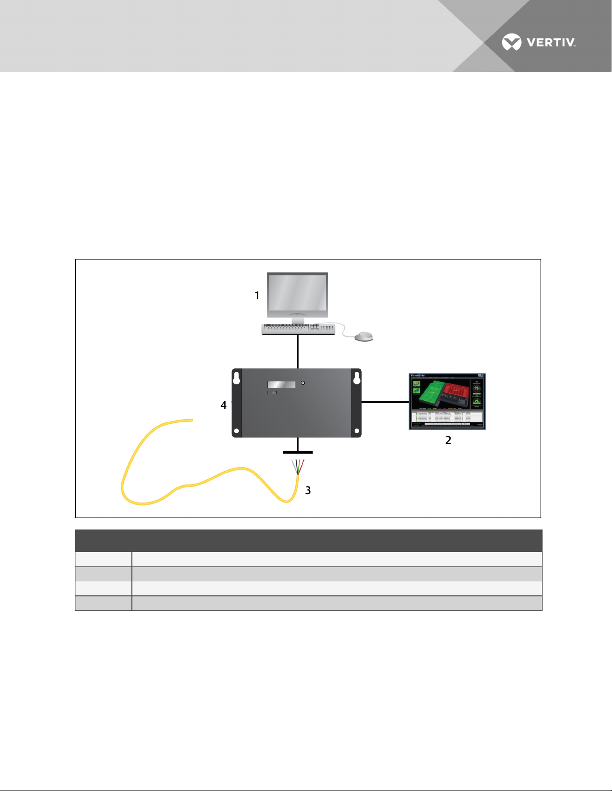
Figure 3.1 LP3000 leak-detection system and communication overview
ITEM DESCRIPTION
1 Webuser interface.
2 BMS/NMS
3 Leak-detection cable
4 Liqui-tect panel
1.1 Supervised System
Liqui-tect LP3000 is a supervised system, which means that it continuously monitors for leaks and other
fault conditions, including a cable break and cable contamination, that trigger an alarm. When a leak or
fault is detected, a relay is activated, and LP3000 sends alarm notifications to predetermined recipients
via the configured communication method.
Vertiv | Liqui-tect LP3000 Installer/User Guide | 5

Table 3.1 System Features
FEATURE DESCRIPTIONS
InputPower Includes an isolatedpower supply with interchangeable blades withinputrange 90–264 VAC, 47/63Hz, 600 mA max.
IncludedA ccess ories 15’ Connection cable andend terminator
Leak Detection Input(1)
Maximum Cable L ength 5,000ft ( 1524m) of LT500 Leak Detection Cable
Minimum Cable Length 35ft (10.67m)
Detection A ccuracy ± 2ft(0.6m) ±0.5% of the cable length
Detection Repeatability ± 2ft (0.6m) ± 0.25% of the cable length
Detection Response Time 5–995 sec, software adjustable in 5-sec increments; ±2sec
Outputs
Form C dry-contact Relay Summary alarm, 1A @ 24VDC; 0.5A@120VAC; L atched or non-latched
Communications Ports
EIA-485 9600, 19200, or 38400 baud (s electable); No parity, 8 data bits, 1 s topbit
RJ-45 10/100BaseT Ethernet port (TCP/IP)
Protocols
TCP/IP, HTML IPv4.0
SNMP V1: V2CMIB-2 compliant: V3
SMTP Supports ClientAuthentication(plain and login); compatible with ES MTP Server s
Modbus Modbus RTU and Modbus TCP/UDP; Master & Slave
BACnet BA CnetMS/TCP andBACnet/IP
Alarm Notification
Audible Alarm 70dBA @ 2ft ( 0.6m); re- sound configurable (disabled, 0-24 hours)
Visible Alarm Dot matrix L ED display; bi-color status L ED and throughweb interface
Email 4 Email recipients; email sent to all recipients on Alar m andReturn to Normal
SNMP Traps 4 IP A ddresses
LoggingCapabilities
Event Log Last 500 events, downloadable to .txtfile
Trend Log Cable current level every day, for the last 288 days
LoginSecurity
WebAcces s Two ( 2) passwords; One (1) Read-only; One (1 ) Read/Write
OperatingEnvironment
Temperature 32° to 1 22°F (0° to 50°C)
Humidity 5% to 95% RH, non-condensing
Altitude 15,000ft (4 ,572m) max.
Storage E nvironment –4° to 158°F (–20° to70°C)
Enclosure Wall mountable; r ack mountbracket LP3000-RMB (optional)
Dimensions 8in. W x 4.25in.H x 1.25in.D (203mmW x 108mmH x 32mmD)
Weight 1.5lb (680g)
Certifications CE; ETL listed: conforms to UL 61010- 1, EN 61010-1; certified to CSA C22.2 NO. 61010- 1; RoHS compliance
Vertiv | Liqui-tect LP3000 Installer/User Guide | 6
1.2 Distance-read Leak Detection
When the Liqui-tect LP3000 measures a current in excess of the defined leak threshold, the
microprocessor computes the distance to the leak, annunciates the leak, and logs the alarm in the event
log. The leak is communicated via the front-panel display and other configured notification methods.
1.3 Communication with Liqui-tect LP3000
A Web-based user interface (UI) provides access to system conditions and settings on-site or via network
communication.
In additon to the web-based UI, LP3000 communicates with external monitoring systems via the following
outputs:
• Modbus via EIA-485, twisted-pair wire, or TCP/IP
• BACnet/IP or BACnet/MSTP
• SNMP
1.4 LP3000 Controls and Displays
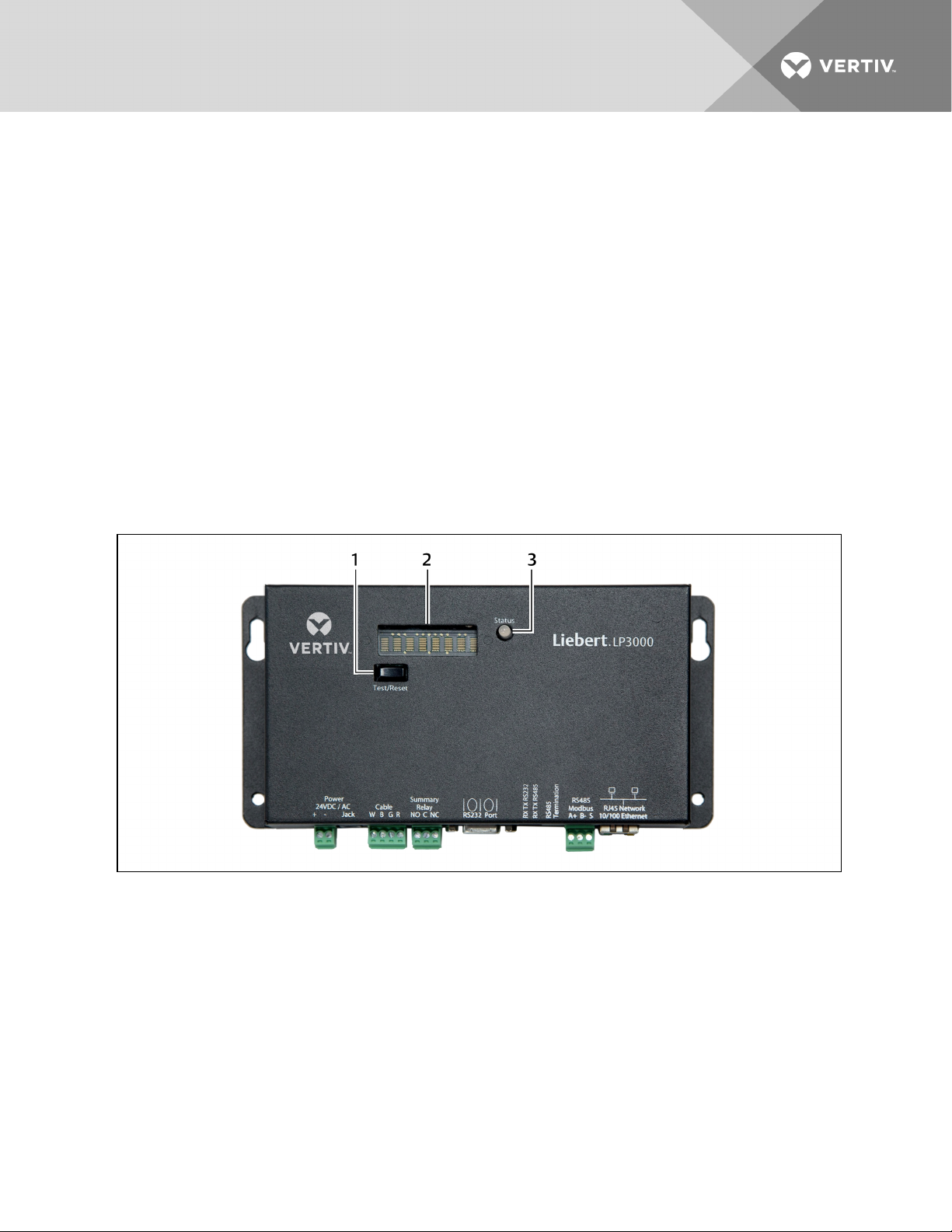
Figure 3.2 LP3000 control and display options
Vertiv | Liqui-tect LP3000 Installer/User Guide | 7

ITEM DESCRIPTION
1 Test/Reset button
2 DigitalLEDdisplay
3 Status LED
1.4.1 Digital LED Display
During normal operation, the digital LED displays the product name with a spinning bar ( | ) to the right of
the name.
When an alarm is present, information about the alarm condition displays. For example, if a leak is
detected, a message about the location of the leak displays as follows:
Leak detected
250 uA
at 675 ft (or 205.74m)
1.4.2 Status LED
The color of the status LEDindicates the operating state of the system.
• Green = powered-on and operating normally.
• Red = an alarm is present.
1.4.3 Test/Reset Button
The Test/Reset button runs a test cycle during normal operation and, during an alarm state, silences the
audible alarm and clears alarms.
To silence the audible alarm:
When the alarm is sounding, briefly press Test/Reset.
The audible alarm turns off, the status LED remains red, and the digital LEDcontinues to display the
alarm condition.
To clear an alarm condition:
Press and hold Test/Reset whether the alarm is sounding or not.
The alarm clears.
To test the system
During normal operation, press Test/Reset.
The LED display cycles through the following 4 lines, then returns to the default display (un-less the ReAlarm Interval is updated, an existing alarm may display. Refer to Leak Settings on page 23.)
LeakageC
nnnn uA
Length
nnn ft (or nnn m)
Vertiv | Liqui-tect LP3000 Installer/User Guide | 8

2 PREPARATION
ANDINSTALLINGTHELIQUI-TECTSYSTEM
Installing the Liqui-tect system involves the following preparation before beginning:
• Choosing a readily-accessible location for the controller (wall mounted, rack mounted, under
raised floor).
• Preparing the appropriate connections for power, leak detection, and communication.
• Consulting with your ITadministrator to determine the following network settings for the
LP3000 controller:
• IP address
• Subnet mask
• Default gateway
• Creating a leak-detection cable layout diagram that considers the equipment in the area that
may be damaged by water and the possible sources of leaks. Plan the cable layout to alert
personnel when electronic equipment is threatened by a leak. An example of a layout diagram
is included in Laying the Leak-detection Cable and Securing to the Floor on page 12.
Required Equipment and Supplies:
The following is included:
• Liqui-tect LP3000 controller
• CONNECT15 connection cable
• LT500-ET end terminator
• Isolated 24 VDC power supply with interchangeable blades
• Screws and anchors for wall mounting
• Crossover cable
The following equipment is sold separately:
• Leak-detection cable(s) of chosen length, 15-ft, 35-ft, or 50-ft
• LP3000-RMB rack-mount bracket
The following tools may be field-supplied, if needed:
• Electric drill (to drive screws or drill pilot holes)
• Screw driver
• Marker/Pencil to mark screw locations
2.1 Mounting the LP3000 Controller on a Wall
1. In the location determined during preparation, mark the wall for the mounting holes using the
unit as a template.
2. If necessary, drill holes for the 4 screws that will secure the unit to the wall.
• If the wall material is not strong enough, use the supplied wall anchors.
• Clean up debris from drilling.
3. Install the 2 top screws, and hang the unit on the screws, allowing it to slip down so the screws
are in the smaller part of the pear-shaped slot.
Vertiv | Liqui-tect LP3000 Installer/User Guide | 9
4. Tighten the screws until snug.
5. Insert the remaining 2 screws in the bottom holes and tighten.
2.2 Mounting the LP3000 Controller in a Rack
If using the optional rack-mount bracket, LP3000-RMB, install LP3000 in the bracket as follows.
1. Place the unit in the bracket with the connectors through the opening.
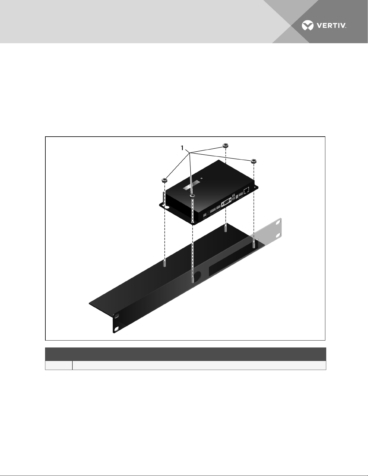
2. Using the 4 nuts, secure the unit to the bracket as shown in the figure below.
Figure 4.1 Tighten nuts in 4 places
ITEM DESCRIPTION
1 Nut
Vertiv | Liqui-tect LP3000 Installer/User Guide | 10
3. Install the bracket in the rack.
Figure 4.2 Liqui-tect installed in rack-mount bracket
2.3 Input and Output Connectors
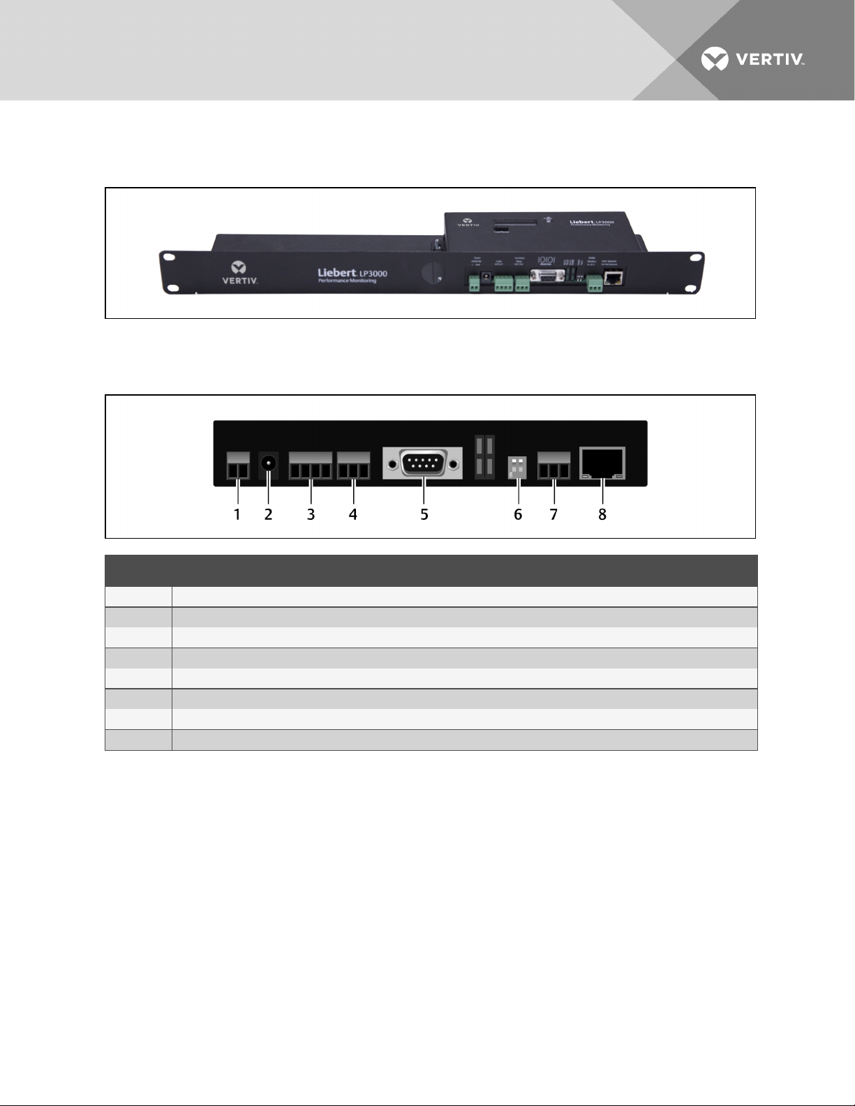
Figure 4.3 Connections on Liqui-tect LP3000
ITEM DESCRIPTION
1 TB1 - input power
2 P1 - inputpower
3 TB2 - leak cable interface
4 TB3 - summary relay
5 P4 - EIA-232 connector
6 SW3 - EIA-4 85 termination
7 TB4 - E IA-485 Modbus port
8 P3 - RJ45 network port
Vertiv | Liqui-tect LP3000 Installer/User Guide | 11
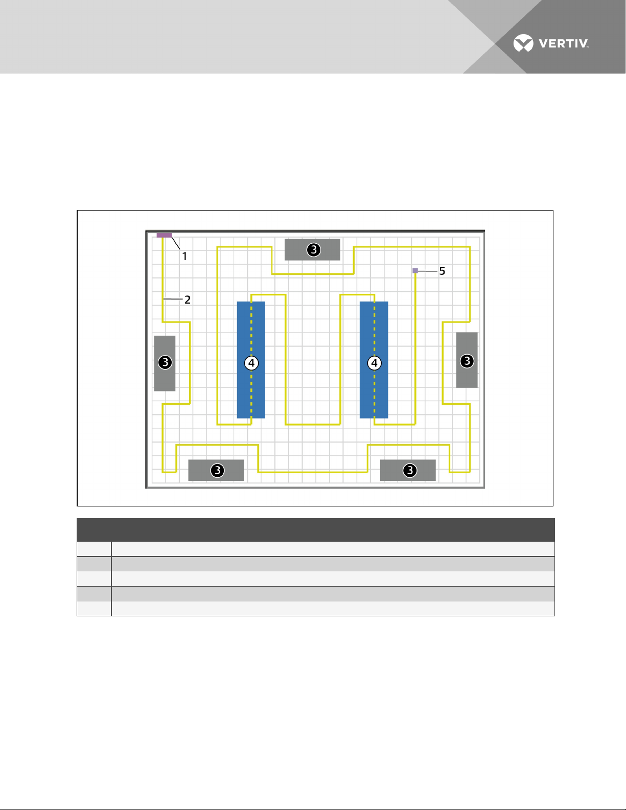
2.4 Laying the Leak-detection Cable and Securing to the Floor
Refer to the site layout diagram for your installation, an example is shown in the following figure, and route
the cable as indicated.
• The leak-detection cable may be placed in the ceiling if there is a liquid source to monitor.
• The cable may also be placed beneath a raised floor.
Figure 4.4 Example leak-detection cable layout diagram
ITEM DESCRIPTION
1 Liqui-tectleak-detectionmonitorings ystem
2 Leak-detectioncable (yellow)
3 Air- conditioning/Environmental units
4 Computer/Equipment rack
5 End terminator ( at endof leak-detectioncable run)
Observe the following guidelines and precautions when installing the leak-detection cable:
• Do not use conductive materials, such as Fire Block or caulk, on the leak-detection cable.
• Do not use any type of adhesive tape to secure the leak-detection cable.
• Do not use a leak-detection cable that is damaged or dirty for example, from plaster, spackle or
debris.
• Do not drag the leak-detection cable through contaminants, such as dirt or grease.
• The floor must be clean for proper leak detection and for the hold-down clips to adhere. Use
isopropyl alcohol to clean the spots on the floor for the hold-down clips.
Vertiv | Liqui-tect LP3000 Installer/User Guide | 12

• Use careful consideration to keep the leak-detection cable's route from the direct path of
discharge air flow from air-conditioning or environmental equipment. If the cable is too close to
the air stream, moisture from the discharge may cause false leak readings. Route the cable at
least 6ft (1.8m) from discharge air flow to avoid nuisance alarms.
• Do not allow soldering or welding near the leak-detection cable without providing protection
from heat and contamination. Also, avoid installing the cable near these types of areas.
• The clip’s adhesive backing does not work well on porous concrete floors. We recommend using
a drop of silicone or another non-conductive adhesive to help secure the clip to the floor.
NOTE: If the leak-detection cable does become dirty or contaminated, refer to Troubleshooting on
page 61 for steps to clean the cable.
To install the cable:
1. Prepare the surface on which the leak-detection cable will be installed to avoid contaminating
the cable. Clean the entire floor as much as possible.
2. Lay the cable in the pattern and route depicted in the layout diagram, maintaining consistent,
uniform contact between the leak-detection cable and the floor.
Vertiv | Liqui-tect LP3000 Installer/User Guide | 13
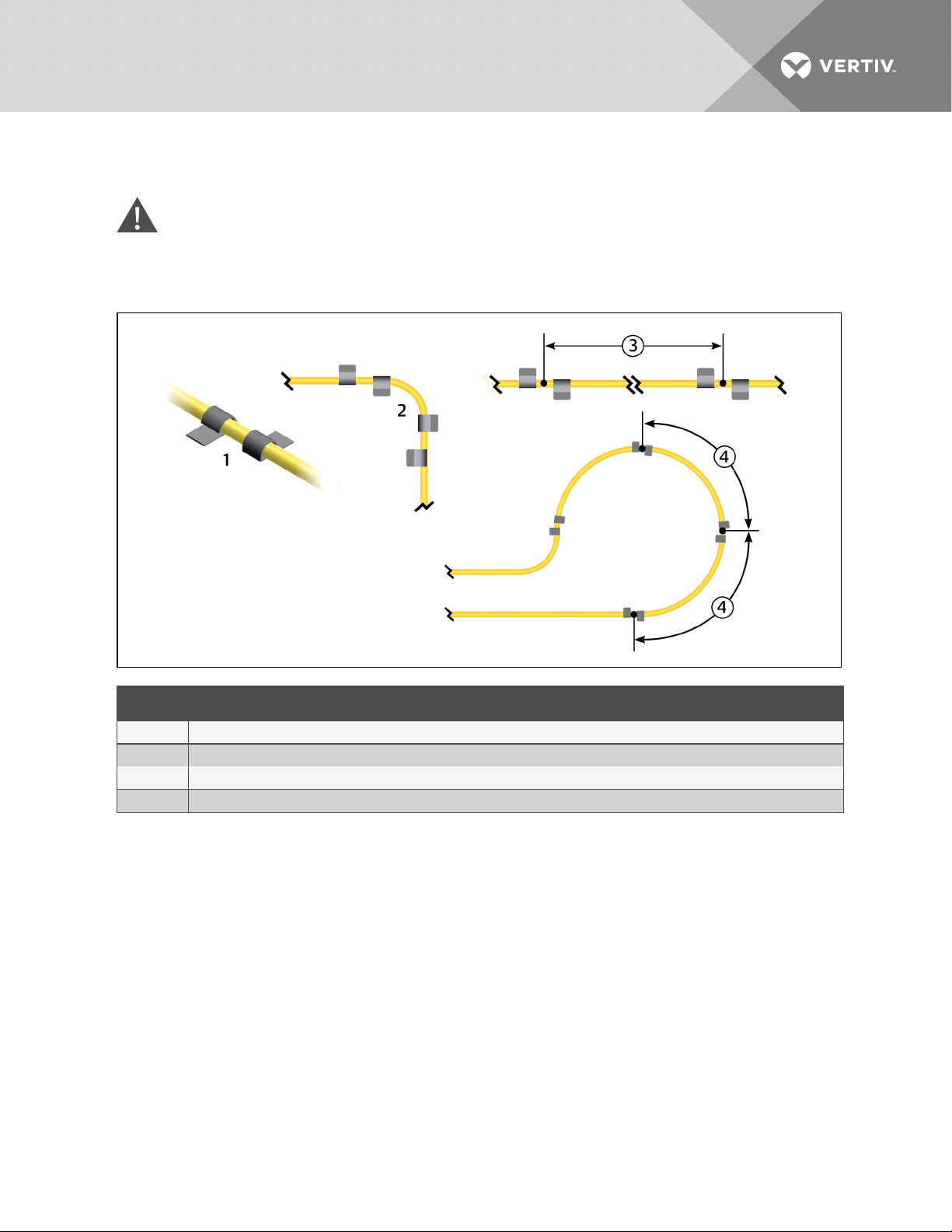
3. Before inserting the cable in the clips, install the hold-down clips in pairs along the route as
shown in the following figure.
CAUTION: Do not allow the adhesive used on the hold-down clips to come in contact with the
leak-detection cable.
Figure 4.5 Hold-down clip installation
ITEM DESCRIPTION
1 Installclips in pairs.
2 On a 90-degree turn, install 1 pair at the beginningof the arc and1 pair at the end of the arc.
3 On straight sections, install 1 pair every 6 to 8 ft (1.8 to2.4m) .
4 In a circular pattern, install 1 pair every 3to4 ft (0.9to1.2m).
4. Allow the adhesive for the hold-down clips to dry completely, then snap the cable into each
clip.
5. Make sure that there are no gaps between the floor and the cable, adding clips as needed.
6. If necessary, make adjustments to the cable-layout diagram to represent the cabling "asinstalled." This diagram will be used to measure and map leak-detection landmarks when
testing the installation.
You are ready to connect the leak-detection cable to the controller. See Connecting the Leak-detection
Cable on page 15.
Vertiv | Liqui-tect LP3000 Installer/User Guide | 14
2.5 Connecting the Leak-detection Cable
The leak-detection cable does not directly connect to the LP3000 controller. The 15-ft connection cable
included with the system connects the controller to the leak-detection cable.
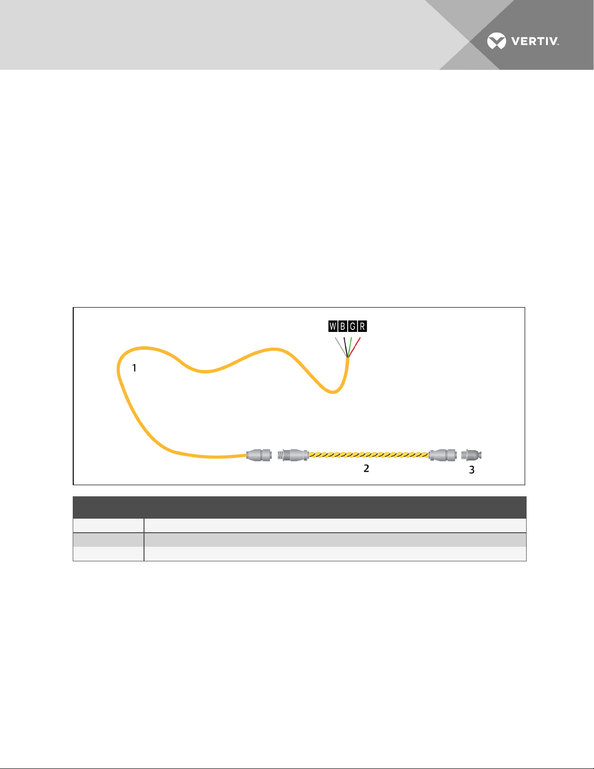
To connect the leak-detection cable to the controller:
1. With the screws of TB2 facing up on the controller, connect the 4, stripped, bare wires of the
connector cable to the terminal block in the following order as shown in the following figure.
• White
• Black
• Green
• Red
NOTE: If the cable is removed from the terminal connector, make sure that the wires remain in the listed
order when the connector is re-installed.
Figure 4.6 Connector cable and leak-detection cable connection to controller
ITEM DESCRIPTION
1 Connector cable (CONNECT 1 5)
2 Leak-detection cable
3 Endterminator (LT500-ET)
2. At the other end of the connector cable, unscrew the end terminator, and attach the male
connector of the leak-detection cable to the connector cable as shown in the figure above.
3. Attach the end terminator to the end of the cable run and to the end of each branchconnector branch.
NOTE: A cable fault will register on the controller display if the end terminator is not attached.
You are now ready to connect power to the controller. See Connecting Power to Liqui-tect on page 16.
Vertiv | Liqui-tect LP3000 Installer/User Guide | 15

2.6 Connecting Power to Liqui-tect
WARNING! Liqui-tect LP3000 requires an isolated power supply. Follow all state and local
codes.
1. Engage a certified electrician to run an isolated power supply to the location of the unit.
2. Connect power to the TB1 or P1 connector on unit, see Input and Output Connectors.
• If using TB1, you may need to cut the barrel connector off the power supply and strip the
ends of the wires to insert them into the terminal blocks.
3. Before applying power to the unit, make sure that all connections are correct and all screw
terminals are secure.
4. Apply power and wait approximately 1minute for the LP3000 to start up.
There may be alarms because the leak-detection cable is not yet connected.
5. Verify that power is connected, and verify that the leak-detection cable is working by touching
it with a clean, moist cloth or paper towel.
If the cable is properly connected, an audible alarm sounds and an alarm notification displays
on the digital display.
NOTE: Do not saturate the leak-detection cable for testing. A small amount of water triggers an alarm,
and the cable must dry for the alarm to clear.
6. Dry the cable to remove the alarm condition. Use a hair dryer to speed up drying if needed.
7. Once you verify that the leak-detection cable is working, you are ready to calibrate the cable,
map leak-detection points and test the installation. See Mapping and Testing the Installation
on page 17.
2.7 Calibrating Resistance to Cable Length
The leak-detection cable has a base resistance of 4 ohms/ft. Because of manufacturing variances, the
base resistance of each length of leak-detection cable may be slightly more or less than 4 ohms/ft, which
means that the displayed length may be slightly more or less than the actual length of the cable.
While a configuration using base resistance values is very accurate, you can fine-tune the resistance to
make it more precise to increase accuracy and bring the reported cable-length value in line with the
actual cable length.
To calibrate cable resistance:
1. Make sure that the LP3000 controller is powered-on, has all sensing cables attached, and that
there are no alarms.
2. Record the following data from the home page of the web UI:
DATA RECORD ED INFO
Cable lengthreported by L P3000.
Cable current
Leg 1 resistance
Leg 2 resistance
Vertiv | Liqui-tect LP3000 Installer/User Guide | 16
3. Select Configuration > Leak Settings, and record the following from the Leak Configuration
page:
DATA RECORD ED INFO
Reportedr esistance per foot
4. To calculate the actual length of the cable: Add the physical length of the cable (the sum of all
of the lengths of installed cable) to the simulated length (the sum of all weighted lengths and
branch connectors installed), refer to the following simulated lengths when determining the
total simulated length.
• LT500-WL simulates 35 ft
• LT500-BC simulates 105 ft
• Jumper cable adds 0 (zero) ft
Calculate the actual length (physical length+simulated length) and record the result.
DATA RECORD ED INFO
Calculatedactual length of cable
5. Verify that the Cable Current recorded is less than 15 µA.
• If the reading is higher than 15 µA, clean the cable using isopropyl alcohol to remove any
contamination from installation.
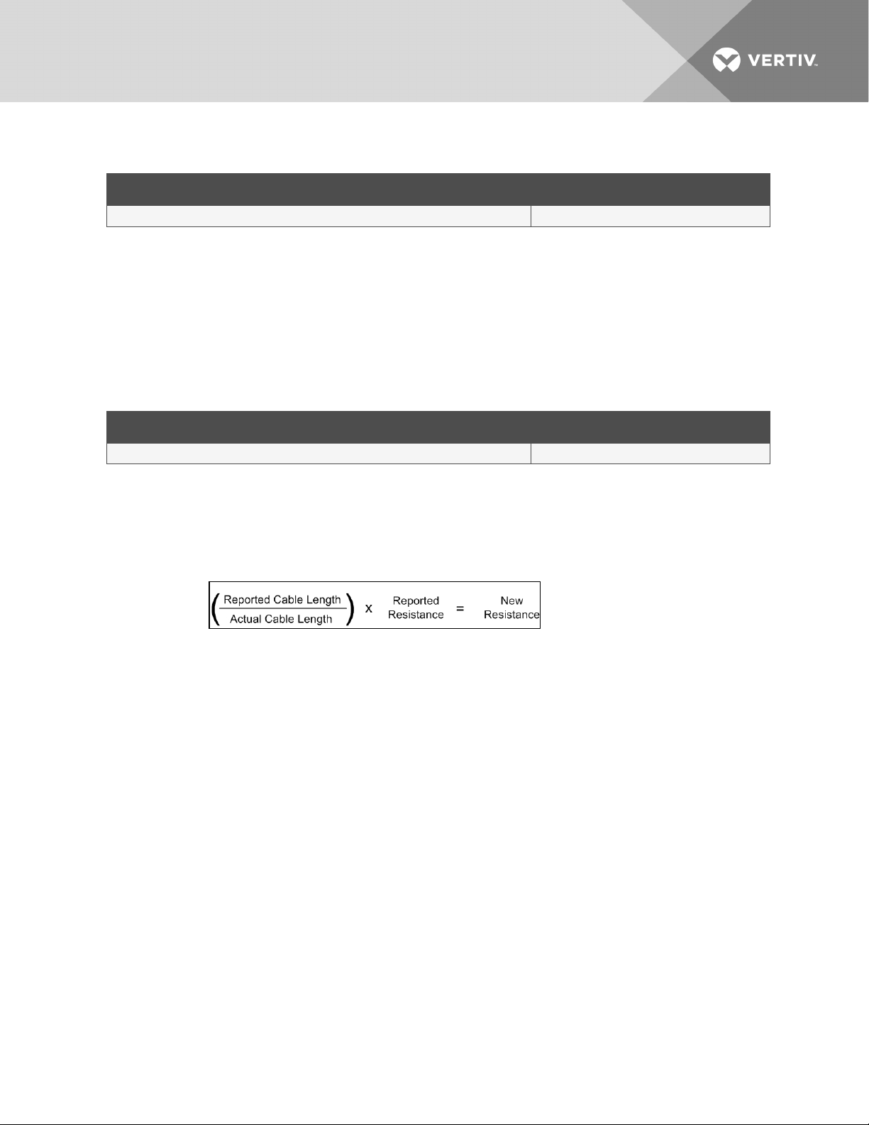
6. Calculate the most-accurate resistance value by dividing the reported cable length by the
actual cable length and multiplying the quotient by the reported resistance.
7. On the Leak Settings page, enter the newly-calculated resistance-per-foot value and click
Submit Changes.
The reported cable length now more-closely matches the physical length of the cable and
thereby improves leak-detected reporting accuracy.
2.8 Mapping and Testing the Installation
NOTE: If the LP3000 controller is already to connected to a BMS or NMS, notify monitoring personnel
before beginning the test.
1. On the "as-installed" cable-layout diagram prepared after laying the leak-detection cable:
• Mark the cable routing, connection points, equipment used in and monitored by the
Liqui-tect system.
• Mark the locations where leak detection is critical and the locations at which the leakdetection cable changes directions. These will be the locations measured and mapped
during testing.
2. Before beginning, set the leak alarm delay to 5 seconds as follows:
• On the web interface, click Configuration > Leak Settings.
Leak Settings on page 23 opens.
• In Leak Alarm Delay, enter 5, then click Submit Changes.
3. At each marked location on the diagram, use one of the following methods to simulate a leak,
and record the reported distance on the diagram:
Vertiv | Liqui-tect LP3000 Installer/User Guide | 17

• Pour a small puddle of water on the cable while it rests on the floor.
• Dunk the cable in a cup of water.
• Soak a paper towel and wrap it loosely around the cable without putting pressure on the
cable.
NOTE: To avoid inaccurate readings, do not grip the cable with your hand.
NOTE: Dry the cable to remove the leak alarm.
4. Verify that the simulated leaks are reported within a few feet of their actual, physical location
based on the diagram.
NOTE: To fine tune the location of leak detections, see Calibrating Resistance to Cable Length on page
16.
5. When finished, remove the source of simulated leaks, reset the leak alarm delay, and return the
system to normal operation.
You are ready to configure communication to the web user interface. See Initial System
CommunicationSetUp on page 19.
Vertiv | Liqui-tect LP3000 Installer/User Guide | 18

3 INITIAL SYSTEM COMMUNICATIONSETUP
Once the LP3000 controller and leak-detection cable are installed and tested, configure communication
with the web UI.
3.1 Configuring Communication totheWebInterface
NOTE: Consult your IT administrator before configuring communication. If you intend to change the IP
Address or Subnet Mask, obtain appropriate addresses from your IT department.
The default addresses for the LP3000 controller are:
• Default IP address: 169.254.24.7
• Default subnet mask: 255.255.0.0
If the address has been changed, use the following steps to get the IP address for the web interface.
Verify the IP address in use:
1. On the front of the LP3000 panel, press and hold the Test/Reset button.
After 5 seconds, the versions and IP address scroll across the display.
2. Keep holding the display until you note the IP address of the LP3000 controller.
When you release the button, the display resumes normal operation.
Connect the computer:
1. On the computer to use for configuration, make sure that WiFi is off and that DHCP is enabled.
2. Using the included cross-over cable, connect to the Ethernet port on the controller.
It may take a minute or two for the computer to connect with the LP3000 controller.
3. Open a Web browser and enter the default IP address, 169.254.24.7, in the address bar.
The Authentication Required dialog opens.
• If the authentication dialog does not appear, temporarily change the computer’s IP
address to the following: IP address 169.254.24.10, subnet mask 255.255.0.0 then re-enter
the default IP address in theweb browser.
4. Enter the default read/write user name and password:
• Default user name: Liebert (case sensitive)
• Default password: Liebert (case sensitive)
The Web UI opens to the home page.
5. On the home page, select Configuration > Network Settings.
Network Settings opens.
6. Enter the values provided by the IT administrator in IP Address, Net Mask (subnet mask), and
Def Route (default gateway), and click Submit Changes.
7. Connect LP3000 to the network with an Ethernet cable.
NOTE: The cross-over cable is not intended to be connected to a network hub, and will not work if it is
connected to a hub.
8. Verify that the change is successful, open a web browser and enter the new IP address entered
for the LP3000 controller, then enter the default user name and password (from Step Enter the
default read/write user name and password: on page 19).
The home page opens.
Vertiv | Liqui-tect LP3000 Installer/User Guide | 19

• If the authentication window does not display, make sure that all cables are firmly
attached, that you entered the correct IP address, and that the Status LED on the
controller is lit green.
Vertiv | Liqui-tect LP3000 Installer/User Guide | 20

4 USING THE WEB INTERFACE
Use the Liqui-tect web user interface (UI) to configure leak-detection and to monitor system status.
NOTE: The default IP address for the LP3000 controller is 169.254.24.7. This may have been changed.
If the address has been changed, use the following steps to get the IP address for the web interface.
Verify the IP address in use:
1. On the front of the LP3000 panel, press and hold the Test/Reset button.
After 5 seconds, the versions and IP address scroll across the display.
2. Keep holding the button until you note the IPaddress of the LP3000 controller.
When you release the button, the display resumes normal operation.
To log-in to the web UI:
1. Open a web browser, and enter the LP3000 controller's IP address in the address bar.
The authentication dialog opens.
2. Enter a User Name and Password, and click Log In.
The default user name and password are as follows. This may have been changed. Contact
your Liqui-tect system administrator for the assigned user name and password.
• Default user name: Liebert (case sensitive)
• Default password:
Read-only access: There is no default password, leave the field blank.
Read/Write access: Liebert (case sensitive)
The web UI opens to the Liqui-tect Home Page on page 21.
4.1 Liqui-tect Home Page
The home page displays system information, including current alarm status, the reported length of the
connected leak-detection cable, the last time an alarm activated, and the running system up-time. The
image can be linked to interactive floor maps.
• To access the home page, click Home on the menu bar.
Vertiv | Liqui-tect LP3000 Installer/User Guide | 21
 Loading...