

Page 1

Liebert® XDP™
50 & 60 Hz, 160kW Nominal Capacity;
ModelRevision5orhigher
User Manual
Page 2

Technical Support Site
If you encounter any installation or operational issues with your product, check the pertinent section of
this manual to see if the issue can be resolved by following outlined procedures. For additional assistance,
visit https://www.VertivCo.com/en-us/support/
Page 3

TABLE OF CONTENTS
Important Safety Instructions 1
1 Product Description 5
1.1 General Product Information 5
1.1.1 Product/System Description 5
1.1.2 Minimum Load 5
1.2 Equipment Inspection 6
1.3 Equipment Handling 6
1.3.1 Handling the Liebert XDP While it is on Skid and Packaged 6
1.3.2 Unpacking the Liebert XDP 7
1.3.3 Removing the Unit from the Skid Using a Forklift 8
1.3.4 Removing the Unit from the Skid using Rigging 8
1.3.5 Moving the Liebert XDP Using Piano Jacks 9
1.3.6 Removing the Unit from the Piano Jacks 10
2 Installation 11
2.1 Mechanical Considerations 11
2.1.1 Positioning the Liebert XDP 11
2.2 Electrical Considerations 12
2.2.1 Connecting High-Voltage Cables 13
2.2.2 External Pump Overloads 16
2.2.3 Extra Low Voltage (ELV) Connections 18
2.2.4 DIP Switch and Jumper Settings for Remote Sensors 20
2.3 Field Connections—Optional for All Units 21
2.4 Remote Sensor Installation—Proper Placement 22
3 Piping 25
3.1 European Union Fluorinated Greenhouse Gas Requirements 25
3.2 Connection Sizes 25
3.2.1 Recommended Pipe Size 25
3.3 Liebert XDP Interconnection with Liebert XD Cooling Modules 26
3.4 Piping Installation Methods 26
3.4.1 Piping Installation—R-134a Pumped Circuit 26
3.4.2 Piping Mains 27
3.4.3 Bypass Flow Controller 27
3.5 Piping Details—Shutoff/Isolation Valves 29
3.5.1 Evacuation and Leak Check—R-134a Pumped Circuit 30
3.5.2 Insulation 30
3.6 Filling the Pumped Circuit—R-134a 31
3.6.1 Calculating Refrigerant Charge—Example 33
3.7 Checklist for Proper Installation 34
4 Liebert iCOM Control—Firmware Version XP1.00.010.STD 35
4.1 Liebert iCOM Components and Functions 35
Vertiv | Liebert® XDP™ User Manual | 3
Page 4

4.2 Display Lamp Indicators 37
4.3 Navigating Through the Liebert iCOM Display 37
4.3.1 Accessing Menus and Settings 38
4.3.2 Cooling Module Overview 38
4.3.3 Entering the Password 39
4.4 Changing Liebert iCOM’s Display Settings 40
4.5 Changing Operational Settings 41
4.6 Graphical Data Record 41
4.7 Liebert iCOM User Menu Icons and Legend 42
4.8 Liebert iCOM User Menu Screens 43
4.9 Liebert iCOM Service Menu Icons and Legend 52
4.10 Liebert iCOM Service Menu Screens 53
5 Start the Liebert XDP with Liebert iCOM 77
5.1 Checklist for Liebert XDP Startup 77
5.2 Starting the Liebert XDP with Liebert iCOM Controller 78
6 Alarm Descriptions and Solutions 81
6.1 Alarm Descriptions 81
6.2 Warning Descriptions 83
6.3 System Shutdown Causes 83
7 Troubleshooting 85
8 Maintenance 88
8.1 Fluorinated Greenhouse Gas Requirements 88
9 Specifications 89
Vertiv | Liebert® XDP™ User Manual | 4
Page 5

IMPORTANT SAFETY INSTRUCTIONS
SAVE THESE INSTRUCTIONS
This manual contains important safety instructions that should be followed during the installation and
maintenance of the Liebert XDP. Read this manual thoroughly before attempting to install or operate this
unit.
Only qualified personnel should move, install or service this equipment.
Adhere to all warnings, cautions, notices and installation, operating and safety instructions on the unit
and in this manual. Follow all operating and user instructions.
Follow all local codes.
WARNING! Risk of arc flash and electric shock. Can cause equipment damage or death.
Disconnect all local and remote electric power supplies and wear protective equipment per
NFPA 70E before working within electric control enclosure. Failure to comply can cause serious
injury or death.
Customer must provide earth ground to unit, per NEC, CEC and local codes, as applicable.
Before proceeding with installation, read all instructions, verify that all the parts are included
and check the nameplate to be sure the voltage matches available utility power.
The Liebert iCOM microprocessor does not isolate power from the unit, even in the Unit Off
mode. Some internal components require and receive power even during the Unit Off mode of
Liebert iCOM control.
The line side of the disconnect switch on the front of the unit contains live high-voltage.
The only way to ensure that there is NO voltage inside the unit is to install and open a remote
disconnect switch. Refer to unit electrical schematic.
Follow all local codes.
WARNING! Risk of unit falling over. Can cause property damage, injury or death.
The XDP is top-heavy. Use extreme caution and care when moving and installing this unit.
Vertiv | Liebert® XDP™ User Manual | 1
Page 6

CAUTION: Risk of piping and component rupture. Can cause equipment damage or injury.
System is pressurized. Relieve pressure through access valve before working on unit. System is
pressurized. Relieve pressure through access valve before working on unit. Closing service
valves may isolate liquid refrigerant, causing high pressure and rupture of piping. Do not close
valves without following recommended procedures for repair, maintenance and replacement of
components. Install pressure relief valves in field piping that may become isolated by service
valves.
Risk of improper installation and/or startup. Can cause injury, equipment damage, or warranty
cancellation. Read and follow completely the installation and start up instructions that are
factory supplied with the unit
CAUTION: Risk of contact with hot surfaces. Can cause injury.The pump motors are extremely
hot during unit operation. Allow sufficient time for them to cool before working within the unit
cabinet. Use extreme caution and wear protective gloves and arm protection when working on
or near the pump motors.
CAUTION: Risk of sharp edges, splinters and exposed fasteners. Can cause injury.Only
properly trained and qualified personnel wearing appropriate safety headgear, gloves, shoes
and glasses should attempt to move, lift, remove packaging from or prepare the unit for
installation.
NOTICE
NOTICE
NOTICE
Risk of leaking chilled water lines. Can cause equipment and building damage.
Lines and joints must be inspected regularly. Improper installation, application and service
practices can result in water leakage from the unit. Water leakage can result in severe property
damage and loss of critical data center equipment. Do not locate unit directly above any
equipment that could sustain water damage. Vertiv recommends installing monitored leak
detection equipment for the unit and supply and return lines.
Risk of overhead interference. Can cause unit and/or building damage.
The unit may be too tall to fit through a doorway while on the skid. Measure the unit and
doorway heights and refer to the installation plans to verify clearances prior to moving the unit.
Risk of damage from forklift. Can cause unit damage.
Keep the forklift tines level and at a height suitable to fit below the skid and unit to prevent
exterior and underside damage.
Vertiv | Liebert® XDP™ User Manual | 2
Page 7
NOTICE
Risk of improper storage. Can cause unit damage.
Keep the Liebert XDP upright, indoors and protected from dampness, freezing temperatures
and contact damage.
NOTE: This document is intended to be used together with site specific documentation and
documentation for other parts of the system (heat rejection devices and cooling modules).
NOTE: Before any action that could cause a disturbance in the XD system’s cooling function is begun,
the facility manager MUST be informed. In addition, after the action is taken and the work is finished,
the facility manager MUST be informed.
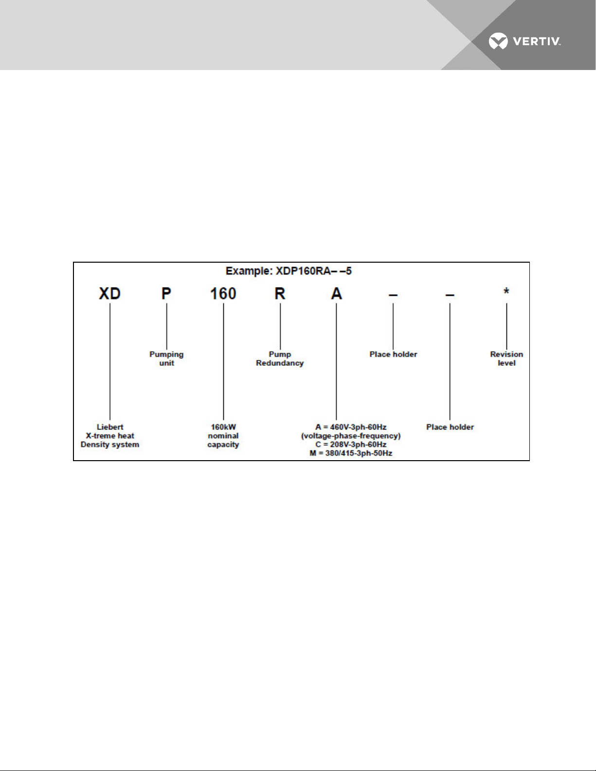
Figure 1.1 Model number nomenclature
Vertiv | Liebert® XDP™ User Manual | 3
Page 8

This page intentionally left blank.
Vertiv | Liebert® XDP™ User Manual | 4
Page 9
1 PRODUCT DESCRIPTION
1.1 General Product Information
1.1.1 Product/System Description
Liebert’s XDP refrigerant distribution unit is an interface between the building chilled water system and
the cooling modules in the Liebert XD system. It is designed to circulate and control refrigerant to the
cooling modules that are in the room with heat-producing equipment. The Liebert XDP is rated for 160kW
(546,000BTU/H) of cooling.
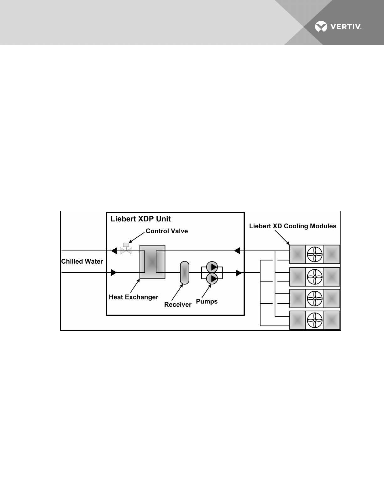
The Liebert XDP consists of a cabinet that includes a heat exchanger, circulating pump(s), control valve,
receiver, controls, valves and piping.
The Liebert XDP monitors room conditions and prevents coil condensation by maintaining the refrigerant
being pumped to the cooling modules at a temperature above the room’s dew point.
All functions, such as switching pumps (if applicable), controlling refrigerant temperature, etc., are
automatic.
Figure 1.1 Liebert XDP components
1.1.2 Minimum Load
The Liebert XDP's minimum recommended operating load is 30% of system nominal capacity. The Liebert
XDP160 is rated for 160kW (546,000BTU/H) of cooling, therefore the system's minimum recommended
load is 48kW (163,800BTU/H). Loading below this value can unfavorably affect system operation. Consult
the factory for any loading below this recommendation.
To achieve the minimum recommended load, the capacity of all connected modules must total at least
48kW (163,800BTU/H). Seethe following table..
Vertiv | Liebert® XDP™ User Manual | 5
Page 10
Table 1.1 Number of Liebert XD cooling modules required to achieve at least 48kW (163,800 BTU/H)
load
Liebert XD Module Type
XDCF10 XDV8 XDV10 XDO16 XDO20 XDH20 XDH32 XDR20
Number ofLiebert XD cooling modules
required to achieve at least 4 8kW
(163,800BTU/H) load
5 6 5 3 3 3 2 3
1.2 Equipment Inspection
When the unit is delivered, inspect all items for visible and concealed damage. Damage should be
immediately reported to the carrier and a damage claim filed with a copy sent to Vertiv and to your sales
representative.
1.3 Equipment Handling
WARNING! Risk of unit falling over. Can cause injury or death.
The Liebert XDP is top-heavy. Use extreme caution when moving and installing this unit. Use
lifting equipment that is rated for the weight of the unit by an OSHA-certified rating
organization. See Table 8.1 on page89 for unit weights. Personnel should be properly trained
and certified to move and rig equipment.
CAUTION: Risk of sharp edges, splinters and exposed fasteners. Can cause injury .
Only properly trained and qualified personnel wearing appropriate safety headgear, gloves,
shoes and glasses should attempt to move, lift, remove packaging from or prepare the unit for
installation.
1.3.1 Handling the Liebert XDP While it is on Skid and Packaged
• Always keep the unit upright, indoors and protected from damage.
• If possible, transport the unit using a forklift truck. Otherwise use a crane with belts or cables. In
either case, do NOT press on the top edges of the packaging.
• If using a forklift, make sure the forks (if adjustable) are spread to the widest allowable distance
to still fit under the skid.
• When moving the skidded unit with a forklift truck, do not lift the unit any higher than 6"
(152mm). If circumstances require the unit to be lifted higher than 6" (152mm), great care must
be exercised and all by-standing personnel are to be no closer than 20 feet (6m) from the lift
point of the unit.
NOTICE
Risk of structural interference. Can cause equipment or building damage.
Vertiv | Liebert® XDP™ User Manual | 6
Page 11
NOTICE
NOTICE
NOTICE
While on the skid, the unit is too tall (83" [2108mm] overall height) to fit through a standard
doorway. Any attempt to move the unit, while skidded, through a standard doorway will cause
damage to the unit and to the building.
Risk of damage from forklift. Can cause unit damage.
Keep tines of the forklift level and at a height suitable to fit below the skid and/or unit to
prevent exterior and/or underside damage.
Risk of improper storage. Can cause unit damage.
Keep the Liebert XDP upright, indoors and protected from dampness, freezing temperatures
and contact damage.
Risk of overtightening securing straps. Can cause damage to panels.
Place a protective material between the straps of the piano jacks and the unit. Ensure that the
straps are not tightened to a point of damaging panels.
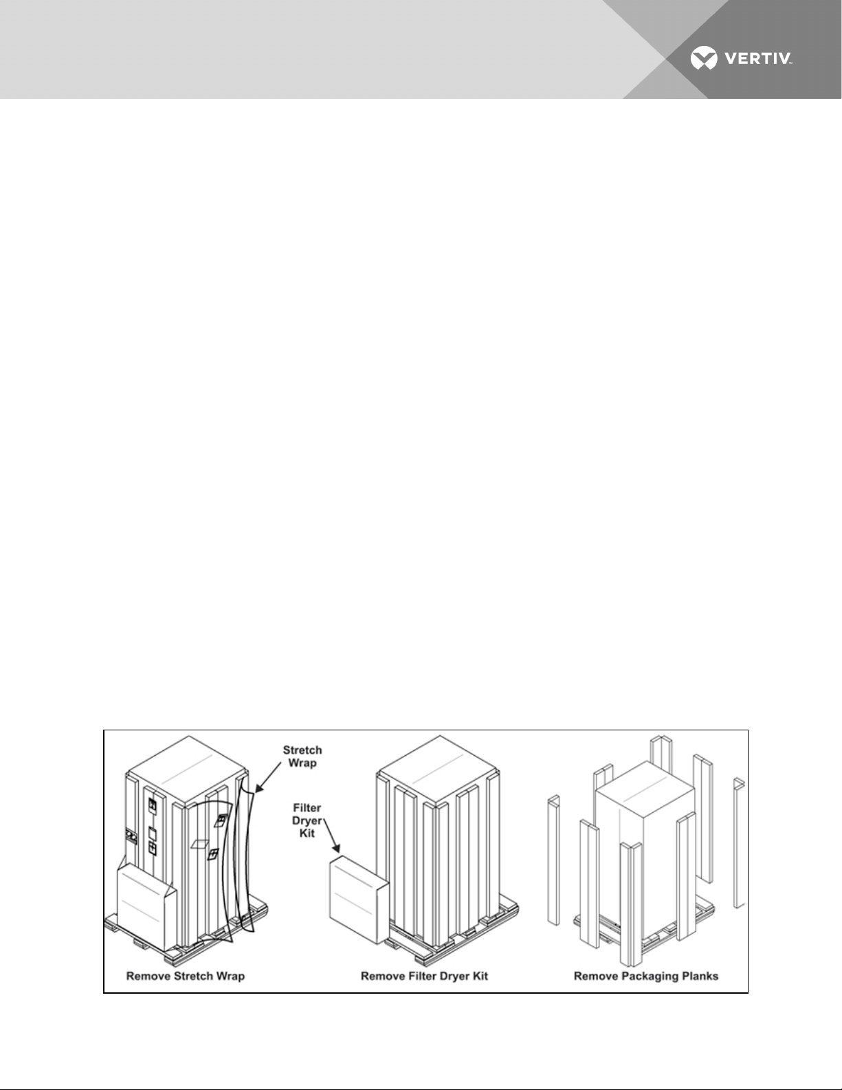
1.3.2 Unpacking the Liebert XDP
1. Remove the exterior stretch wrap packaging from the unit, exposing the protective corner and
side packaging planks.
2. Remove and set aside filter dryer kit.
3. Remove the corner and side packaging planks from the unit, exposing the bag over the unit.
The bag may remain in place for dust and panel protection or removed for immediate unit
installation.
4. Remove the bag from the unit when ready to remove the skid for installation.
Figure 1.2 Unpacking the Liebert XDP
Vertiv | Liebert® XDP™ User Manual | 7
Page 12
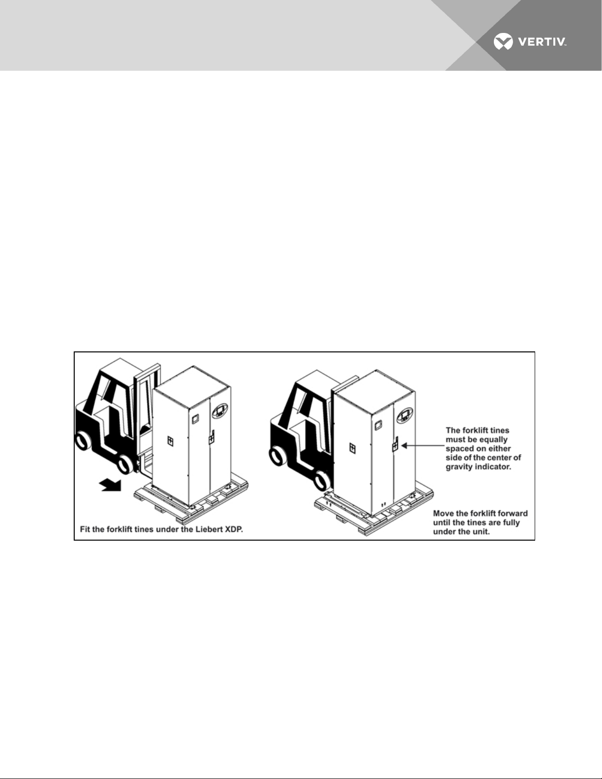
1.3.3 Removing the Unit from the Skid Using a Forklift
1. Align the forklift with either the front or rear side of the unit.
Make sure the tines of the forklift are locked to the widest position.
Use the center of gravity indicators to determine the entry points for the tines. The tines must
be equally spaced on either side of the center of gravity indicator.
2. Insert the tines of the forklift under the unit.
Make sure the tines are level. The tines must be low enough to fit under the unit without
damaging it.
Make sure the tines extend beyond the opposite side of the unit.
3. Remove the 12 lag bolts and two brackets that secure the unit to the skid.
NOTE: Each lag bolt is 1-1/2" (38mm) long. They can be removed with a 9/16" socket or wrench.
4. Lift the unit to a height that it is not being support by the skid.
5. Move the skid from under the unit.
Figure 1.3 Use a forklift to remove the Liebert XDP from the skid
1.3.4 Removing the Unit from the Skid using Rigging
1. Use the center of gravity indicators on the unit to position the slings. The slings must be
equally spaced on either side of the center of gravity indicator. Refer to Figure 1.4 on the
facing page.
2. Place slings under the unit using spaces provided between the skid deck boards.
NOTE: Unit is shown without outer packaging. These instructions may be applied with the outer
packaging in place
3. Use spreader bars or an equivalent method to ensure proper protection of the unit.
4. Ensure that the panels, if attached, are well protected from the slings.
Vertiv | Liebert® XDP™ User Manual | 8
Page 13
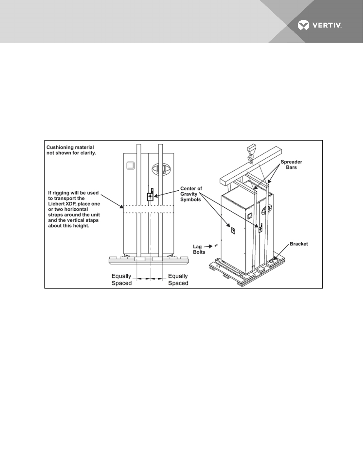
NOTE: If rigging is to be used to move the unit closer to the site for installation, place one or two
horizontal straps around the unit and vertical straps at mid height.
5. Remove the 12 lag bolts and two brackets that secure the unit to the skid.
NOTE: Each lag bolt is 1-1/2" (38mm) long. They can be removed with a 9/16" socket or wrench.
6. Lift the unit off of the skid to an elevation point where the skid is not supporting the weight of
the unit.
7. Remove the skid from under the unit.
Figure 1.4 Removing the unit from the skid using rigging
1.3.5 Moving the Liebert XDP Using Piano Jacks
1. Elevate the Liebert XDP with a lifting mechanism, such as a forklift or rigging.
1. Position one piano jack at each end of the Liebert XDP.
2. Lower the unit to a height suitable for placing it on the piano jacks.
3. Put protective material between the Liebert XDP and the piano jacks and straps.
4. Secure the Liebert XDP to the piano jacks.
5. Release the the Liebert XDP from the straps securing it to the lifting mechanism and move the
mechanism away from the unit.
Using the piano jacks, at least two properly trained and qualified personnel can move the unit.
Vertiv | Liebert® XDP™ User Manual | 9
Page 14
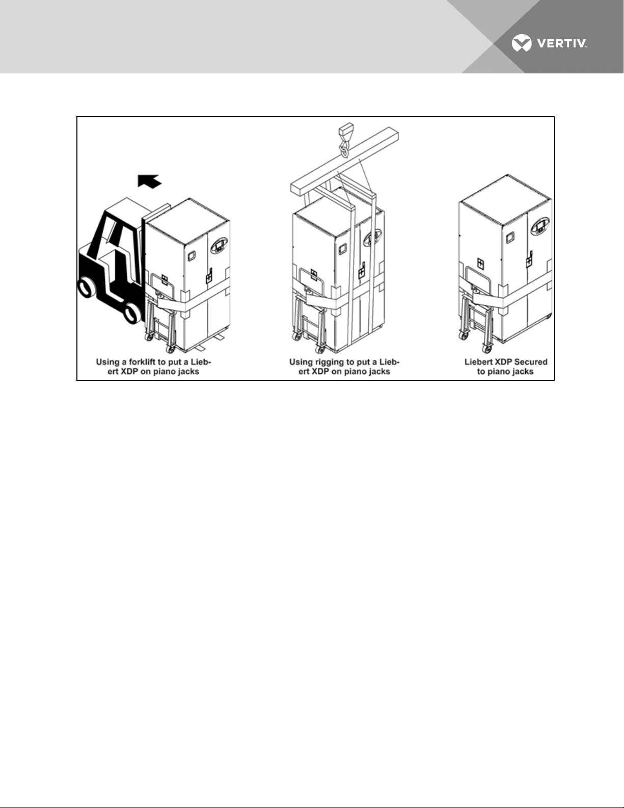
Figure 1.5 Securing the Liebert XDP to piano jacks
1.3.6 Removing the Unit from the Piano Jacks
1. Lower the Liebert XDP as far as the piano jacks will allow.
2. Undo all strapping holding the piano jacks to the unit.
3. Lift one end of the Liebert XDP off one piano jack with a pry bar or similar device, taking care
not to damage the unit’s cabinet.
4. Repeat step 3 to remove the piano jack from under the opposite end of the Liebert XDP.
5. Remove all material used to protect the unit from the piano jacks and strapping.
Vertiv | Liebert® XDP™ User Manual | 10
Page 15
2 INSTALLATION
2.1 Mechanical Considerations
2.1.1 Positioning the Liebert XDP
Install the Liebert XDP according to the site specific documentation and secure the unit to the floor.
The Liebert XDP can be installed near a wall or another Liebert XDP. However, there must be at least
3feet(92cm) clearance in front of the Liebert XDP as service access for components in the unit.
For additional technical information, refer to the System Design and Configuration Document for the
Liebert XD™System, SL-16655. The document is available in electronic format at Vertiv’s Web site,
www.VertivCo.com, as well as from your local Vertiv representative.
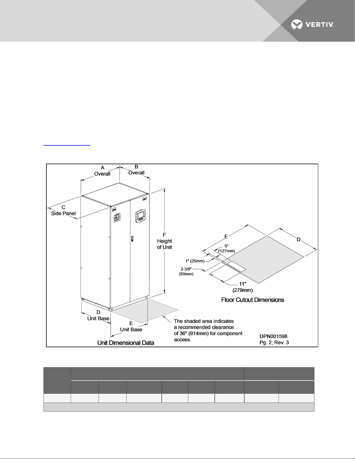
Figure 2.1 Dimensions
Table 2.1 Liebert XDP Dimensions
Model
50/60Hz
XDP160 38(965) 34 (864) 33-1/ 8 ( 841) 33 (838) 36 (914) 78 (1981) 1 020 (462) 1083 (491)
*The dimension does not include the bezel of the disconnect switch.
Vertiv | Liebert® XDP™ User Manual | 11
Dimensional Data, inches (mm) Shipping Weight, lb. (kg)
A B* C D e H Domestic Export
Page 16

Figure 2.2 Piping access points
Table 2.2 Unit piping outlet connection sizes, inches, OD Cu
Model Pipe ConnectionPoint
50/60 Hz A B C D
XDP160 2-1/8 1-1/8 2-5/8 2-5/8
2.2 Electrical Considerations
Make sure the actual supply voltage and frequency correspond to the voltage and frequency indicated
on the Liebert XDP’s rating plate. The unit must be installed in accordance with national wiring
regulations.
Vertiv | Liebert® XDP™ User Manual | 12
Page 17

Connect cables for high voltage supply to the electrical box in the Liebert XDP according to Figure 2.5 on
page16 and make sure that the phases are correctly connected.
WARNING! Risk of electric shock. Can cause injury or death.
Disconnect all local and remote electric power before working within the unit
WARNING! Risk of electrical shock, short circuit and/or control malfunction. Can cause
equipment damage, injury or death.
Damage to wiring or components can make unit unsafe to operate.
Use caution when installing wiring to prevent damage to factory wiring.
Install protective bushings in wiring knockouts as required to protect wiring from sharp edges.
Do not disturb factory wiring or route field-installed wiring over electrical terminals.
Use NEC Class 1 wiring for all hazardous voltage electrical power supplies.
Check and retighten all wiring connections before starting the unit.
2.2.1 Connecting High-Voltage Cables
1. Turn the Liebert XDP’s disconnect switch to the Off position (see Figure 2.3 on the next page).
Open the front doors and push down on the enclosure cover latch to open the hazardous
voltage enclosure cover.
Vertiv | Liebert® XDP™ User Manual | 13
Page 18
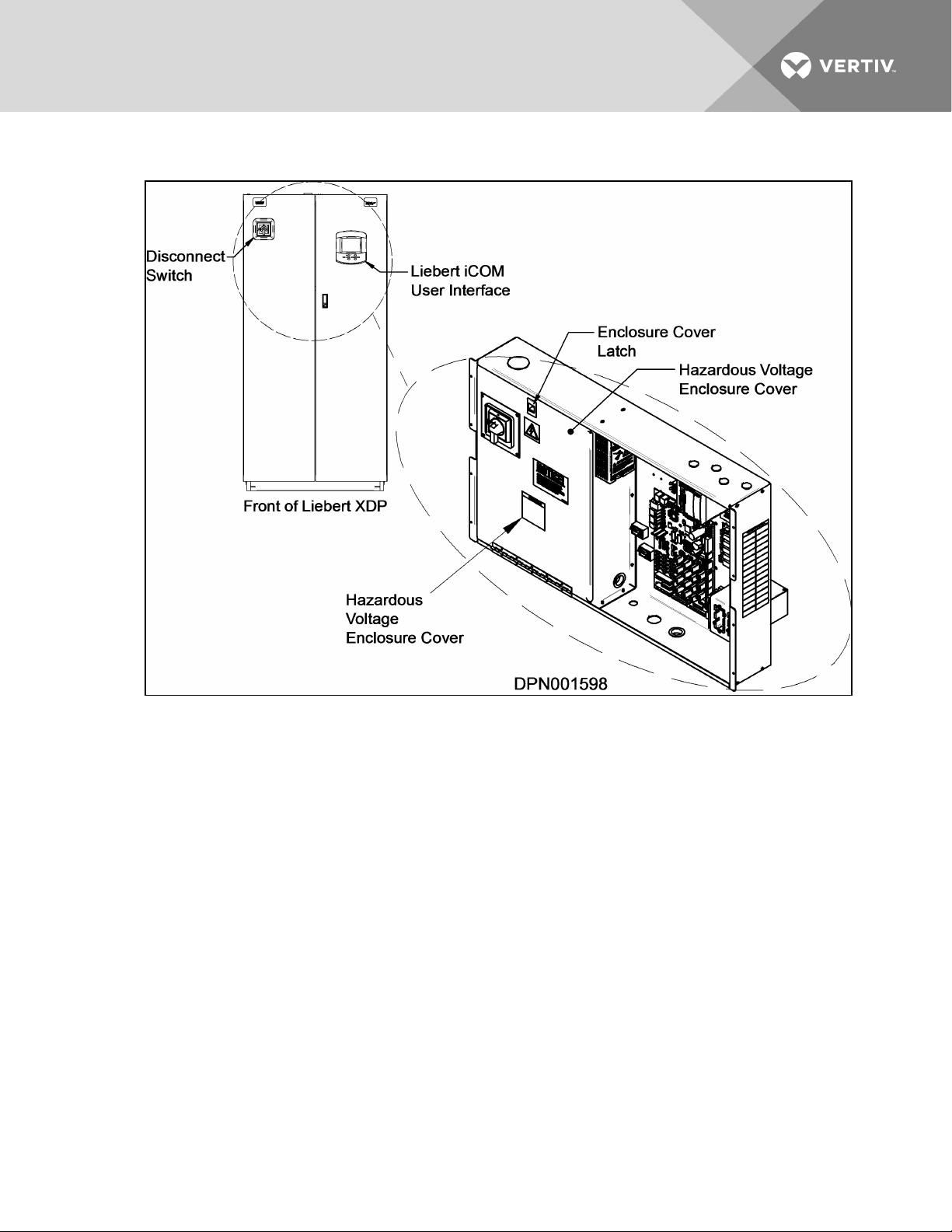
Figure 2.3 Front view of Liebert XDP and electrical enclosure
2. Determine which knockouts in the electrical enclosure will be used and remove them (see
Figure 2.4 on the facing page).
Vertiv | Liebert® XDP™ User Manual | 14
Page 19
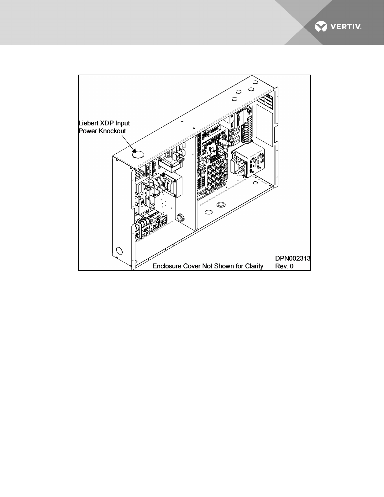
Figure 2.4 Electrical enclosure knockout location for hazardous voltage wiring
3. Route the input hazardous voltage electrical power wiring through the top left knockout (see
Figure 2.4 above) to the disconnect switch L1, L2 and L3 (see Figure 2.5 on the next page
andFigure 2.6 on the next page). Observe proper phasing.
4. Connect the ground wire to the ground lug (see Figure 2.5 on the next page andFigure 2.6
on the next page), which is in the middle left of the enclosure.
Vertiv | Liebert® XDP™ User Manual | 15
Page 20
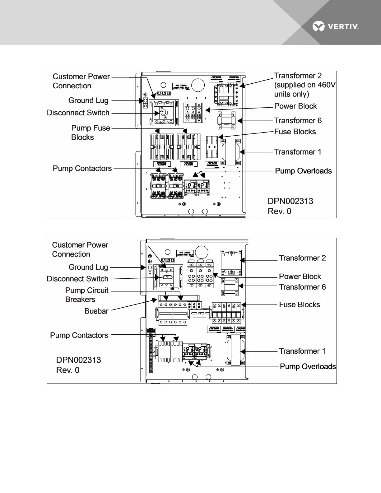
Figure 2.5 High voltage connections—60Hz
Figure 2.6 High voltage connections—50Hz
2.2.2 External Pump Overloads
The Liebert XDP is shipped with external pump overload with trip point settings and DIP switch settings
for normal operations. The trip points are in increments of 0.25A and should not be changed from the
factory settings. For 460V, the trip point is set at 1.5A (Figure 2.7 on the facing page). For 208V, the trip
point is set at 2.7A (Figure 2.8 on the facing page). See Figure 2.9 on page18 for factory DIP switch
settings for normal operation with reset mode set as automatic and Trip Class 20.
Vertiv | Liebert® XDP™ User Manual | 16
Page 21
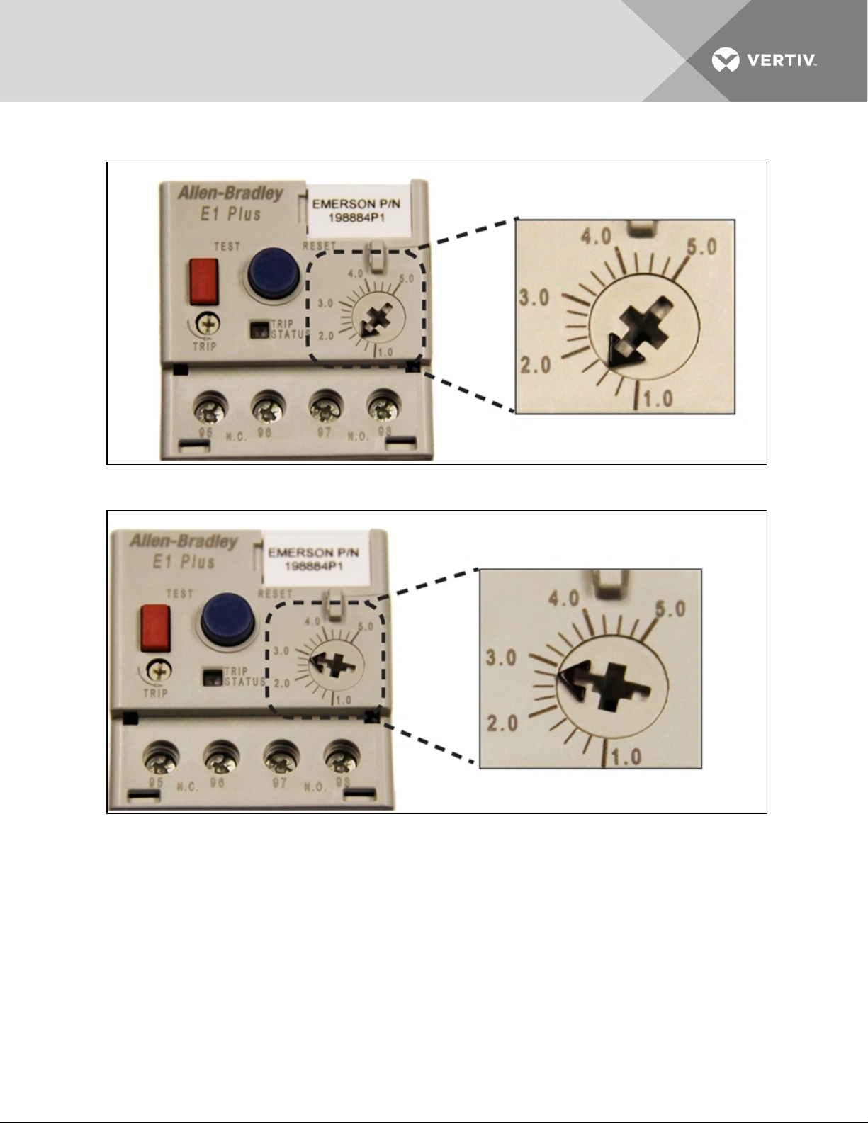
Figure 2.7 460V factory setting external pump overload trip point
Figure 2.8 208V factory setting external pump overload trip point
Vertiv | Liebert® XDP™ User Manual | 17
Page 22
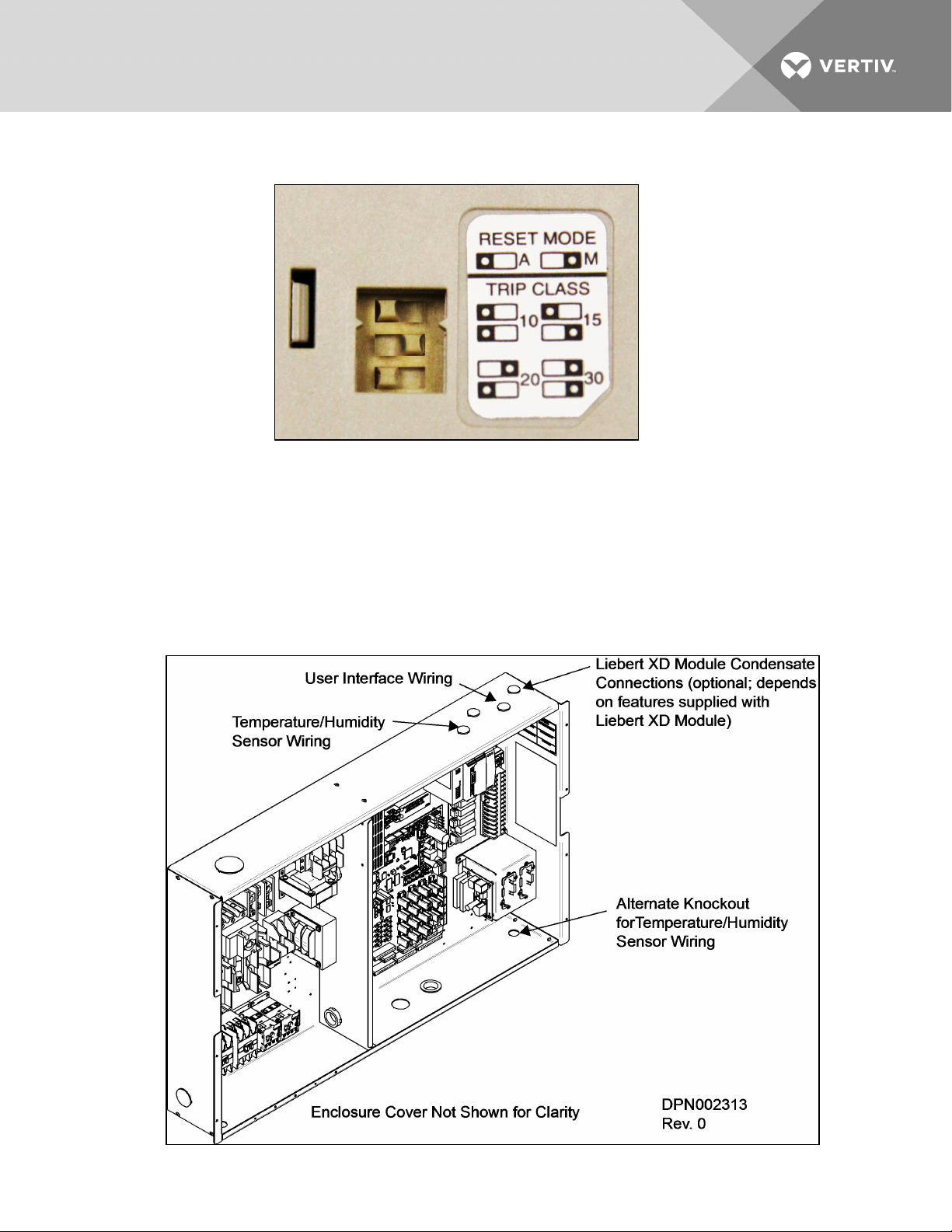
Figure 2.9 Factory DIP switch settings
2.2.3 Extra Low Voltage (ELV) Connections
Extra Low Voltage power output is 30V and 100VA or less.
1. Turn off all unit power before connecting cables or wires. Failure to do so may damage this
equipment (refer to Figure 2.10 below).
2. Route low voltage electrical connections through the appropriate knockouts as indicated
below.
Figure 2.10 Electrical enclosure knockout locations for Extra Low Voltage
Vertiv | Liebert® XDP™ User Manual | 18
Page 23

Figure 2.11 Connecting the remote temperature/humidity sensors
Vertiv | Liebert® XDP™ User Manual | 19
Page 24
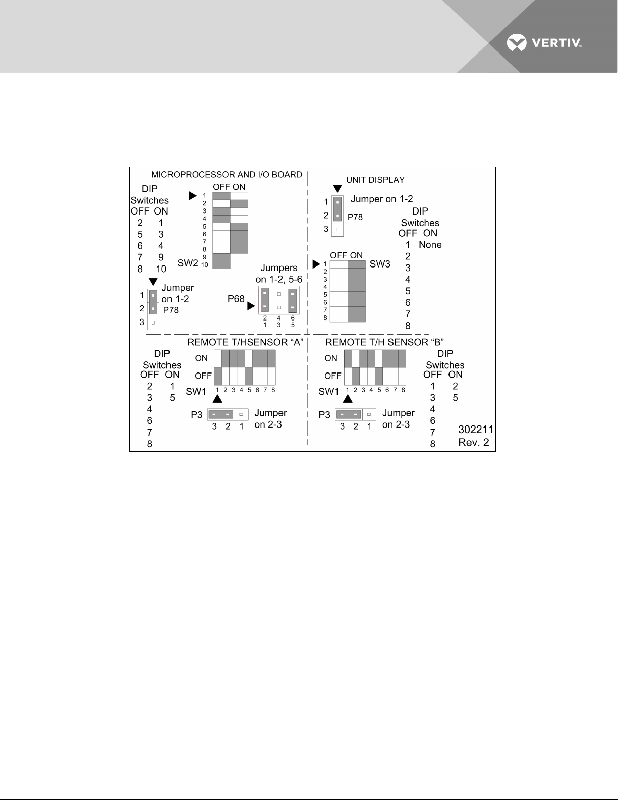
2.2.4 DIP Switch and Jumper Settings for Remote Sensors
The Liebert XDP is shipped with jumpers and DIP switch settings for normal operation. See Figure 2.12
below.
Figure 2.12 DIP switch and jumper settings
Vertiv | Liebert® XDP™ User Manual | 20
Page 25
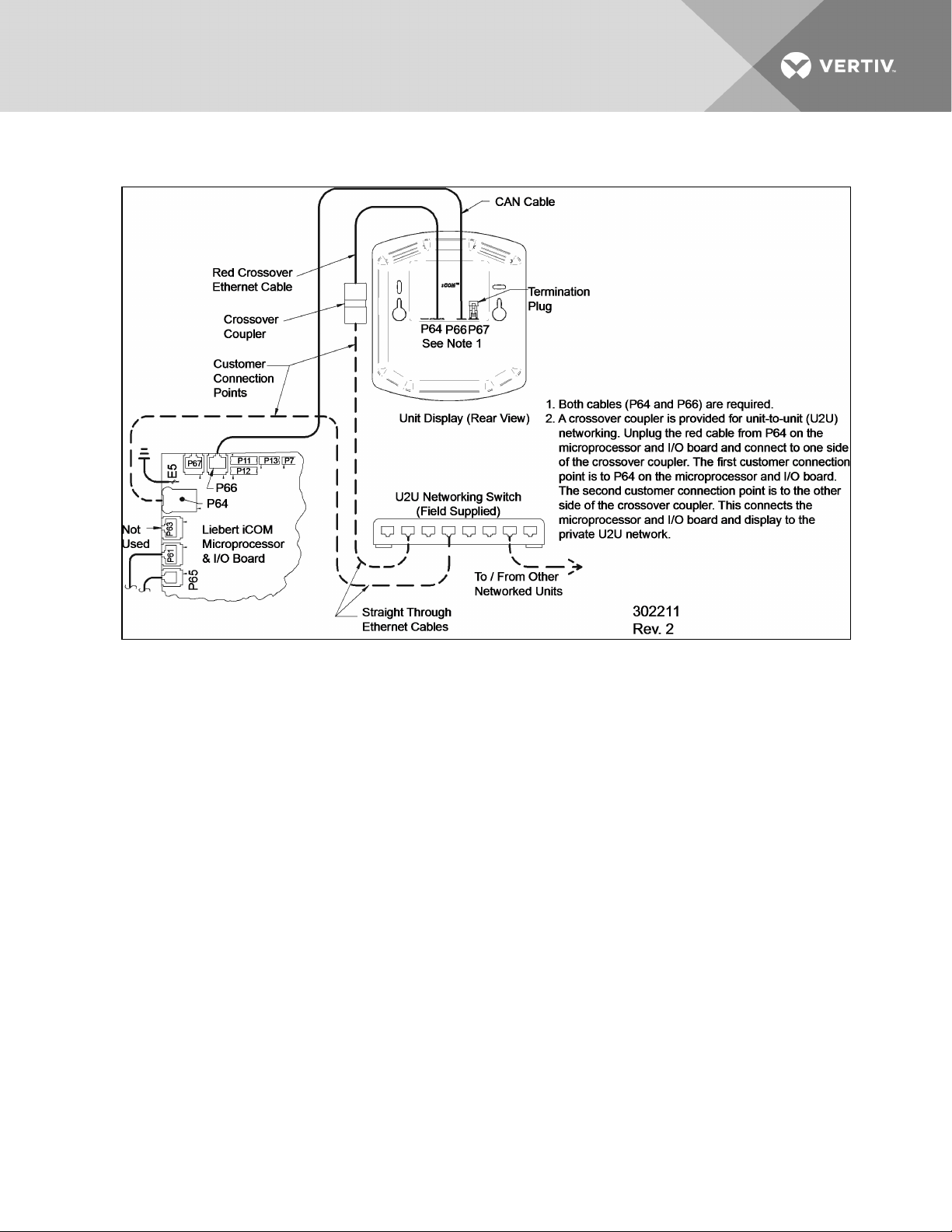
Figure 2.13 Unit-to-unit networking connections
2.3 Field Connections—Optional for All Units
• Connect field wiring from the optional Liebert XD cooling module condensation detection
circuit to terminal strip locations COMM. (24) and H2O (51).
• Connect optional field wiring from remote devices to remote alarm device, common alarm
outputs, site monitor and remote shutdown, if applicable. See terminal strip descriptions in
Figure 2.14 on the next page.
Vertiv | Liebert® XDP™ User Manual | 21
Page 26
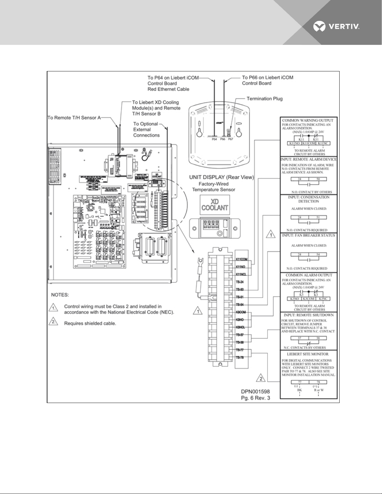
Figure 2.14 Liebert XDP extra low voltage field connections points
2.4 Remote Sensor Installation—Proper Placement
Placement of the two remote temperature/humidity sensors is critical to effective cooling of the
conditioned space.
Vertiv | Liebert® XDP™ User Manual | 22
Page 27
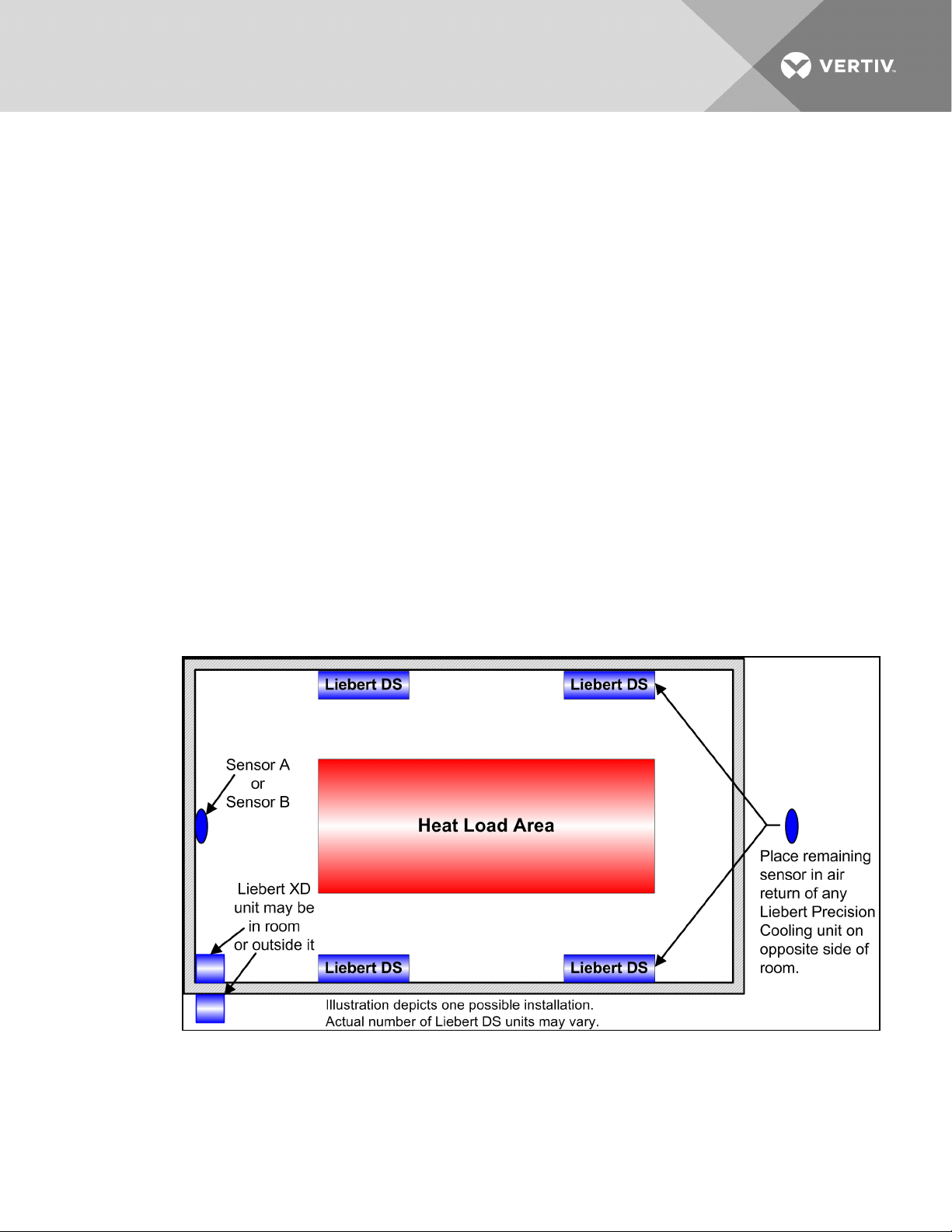
The remote sensors must be installed in areas where conditions are representative of the space
conditioned by the Liebert XDP. Vertiv recommends installing the sensors in different areas near the
cooling modules served by the Liebert XDP. If the return air side of the primary air mover, such as a
Liebert DS, represents the conditions where the Liebert XD cooling modules are located, one sensor could
be placed there. Vertiv suggests placing the other sensor on the wall opposite the heat load area (see
Figure 2.15 below for guidance).
Do not install the sensors where ambient air might cause false readings, for example, near unsealed doors
or windows, or areas with stagnant air.
1. Unpack the two remote temperature/humidity sensors and cables.
One sensor is labeled Sensor A and the other Sensor B. The sensor cables are interchangeable;
each bears labels indicating Sensor End and Unit End.
2. Connect the Sensor End of one of the supplied sensor cables to P66 on Sensor A (see Figure
2.11 on page19).
3. Connect the Unit End of the sensor cable to P67 on the Liebert iCOM input/output board
inside the Liebert XDP. Secure the ring terminal on the cable shield to the electric box adjacent
to P67 (see Figure 2.11 on page19).
4. Connect the Sensor End of the second sensor cable to P66 on Sensor B (see Figure 2.11 on
page19).
5. Connect the Unit End of the cable to P67 on the Liebert iCOM display (see Figure 2.11 on
page19). Secure the ring terminal on the cable shield to the grounding screw adjacent to P67.
Figure 2.15 Suggested remote sensor placement
Vertiv | Liebert® XDP™ User Manual | 23
Page 28

This page intentionally left blank.
Vertiv | Liebert® XDP™ User Manual | 24
Page 29
3 PIPING
3.1 European Union Fluorinated Greenhouse Gas Requirements
Stationary air conditioning, refrigeration, heat pump equipment and stationary fire protection systems in
the European Community market and operating with fluorinated greenhouse gases (f-gas), such as
R407C, R134a, R410A, must comply with the F-Gas Regulation: (EC) No. 842/2006 (F-gas). The regulation
prohibits, among other actions, venting fluorinated greenhouse gases to the atmosphere.
The F-Gas Regulation requires operators to use all measures that are technically feasible and do not
entail disproportionate cost to prevent leakage of these gases, to test for leakage regularly and to recover
f-gas before disposing of equipment, as well as during service and maintenance.
Refer to the full regulation for additional details.
3.2 Connection Sizes
The copper pipe connections on the Liebert XDP are:
Building Chilled Water
Supply
Building Chilled Water
Return
2-5/8" OD
2-5/8" OD
Refrigerant Supply 1-1/8" OD
Refrigerant Return 2-1/8" OD
3.2.1 Recommended Pipe Size
Connect the main pipes between the Liebert XDP and the Liebert XD cooling modules according to site
specific documentation and the configuration guide for the Liebert XD system.
Elbows and restrictions must be minimized to get good fluid flow.
Table 3.1
Supply, return pipe sizes for refrigerant loop
Pipe Function Size / Equivalent Pipe Length
Liebert XDP supply line, from Liebert XDP supply
to farthest L iebert XD cooling module
Liebert XDP return line, from farthest Liebert XD cooling
module to Liebert XDP return
From any model Liebert XDO/Liebert XD H supply
to supply line of L iebert XDP
From any model Liebert XDO/Liebert XD H return
to return line of Liebert XDP
From any model Liebert XDV/Liebert XDCF s upply
to supply line of L iebert XDP
From any model Liebert XDV/Liebert XDCF r eturn
to return line of Liebert XDP
1-1/8" OD for lengths upto 60 feet
1-3/8" OD for lengths over 60 but less than175 feet
2-1/8" OD for lengths up to 60 feet
2-5/8" OD for lengths over 60 but less than175 feet
1/2" OD for lengths upto 10 feet
7/8" OD for lengths over 10 butless than 25 feet
7/8" OD for lengths up to 10 feet
1-1/8" OD for lengths over 1 0 but less than 25 feet
1/2" OD for lengths upto 10 feet
5/8" OD for lengths over 10 butless than 35 feet
5/8" OD for lengths up to 10 feet
7/8" OD for lengths over 10 butless than 35 feet
Vertiv | Liebert® XDP™ User Manual | 25
Page 30

3.3 Liebert XDP Interconnection with Liebert XD Cooling Modules
All piping must be ASTM (American Society for Testing and Materials) Type ACR copper pipe.
The Liebert XDP may be connected to Liebert XD cooling modules with either Liebert’s XD prefabricated
piping assembly or with rigid, off-the-shelf piping. In either setup, piping for the Liebert XD system is
arranged in a manner similar to piping for a chilled water system. Liebert XD cooling modules are
connected in parallel between main return and supply pipes going to and from the Liebert XDP/Liebert
XDC. Figure 3.1 below represents a typical configuration. For piping details, refer to Liebert’s XD System
Design Manual, SL-16655, available at Vertiv’s Web site: www.VertivCo.com. The guidelines provided for
pipe size must be strictly followed. Failure to size the main lines and connection lines adequately may
result in reduced cooling capacity. The critical aspects of pipe sizing are related to refrigerant volume and
pressure drop. Each must be minimized.
Figure 3.1 Liebert XD system diagram
3.4 Piping Installation Methods
The assembly and connection means used for piping in the Liebert XD system are similar to those used
for conventional refrigeration systems. All piping should be installed with high-temperature brazed joints.
Soft soldering is not recommended.
During brazing, the lines must be filled with flowing dry nitrogen to prevent excessive oxidation and scale
formation inside the piping. Prevailing good refrigeration practices must be employed for piping supports,
leak testing, dehydration and charging. Failure to use good system practices may result in damage to the
system. Refer to the ASHRAE refrigeration handbook for general good-practice refrigeration piping.
Insulate all piping lines to prevent condensation in applications where the dew point approaches the R134a refrigerant temperature.
Vertiv recommends venting the pressure relief valve for the R-134a outside the conditioned space where
it is open to the atmosphere. The R-134a side relief valve is inside the Liebert XDP unit at the top of the
receiver.
3.4.1 Piping Installation—R-134a Pumped Circuit
Vertiv recommends venting the relief pressure valve of the Liebert XDP (located at the top of the
receiver) outside of the conditioned space where it is open to the atmosphere.
Vertiv | Liebert® XDP™ User Manual | 26
Page 31

3.4.2 Piping Mains
All refrigeration piping mains connected to the Liebert XD cooling module, both supply and return, should
be installed with a downward pitch toward the Liebert XDP of 1-2" for every 20 feet (25.4-51mm per 6m) of
pipe run.
Install a 20-40 mesh strainer on the chilled water supply to the Liebert XDP. The strainer is needed to
prevent particles in the chilled water from entering the Liebert XDP’s heat exchanger.
3.4.3 Bypass Flow Controller
Three bypass flow controllers are required to ensure that the Liebert XDP pumps operate within the
optimum range. These devices are added to the field piping and simulate the flow of additional cooling
modules.
Each bypass flow controller must be installed with one shutoff valve to allow the controller to be disabled
when cooling modules are added to a Liebert XD system.
Bypass flow controllers should be connected between the main supply and the main return lines of the
field piping. The connection points to the main supply and return lines should be in a convenient and
accessible location between the Liebert XDP/Liebert XDC and the first Liebert XD module in the circuit.
See Figure 3.2 on the next page andFigure 3.3 on the next page for piping details of the bypass flow
controller.
Refer to Table 3.2 below to determine the number of bypass flow controllers that must be open to provide
proper refrigerant flow based on the total nominal cooling capacity of the cooling modules in each Liebert
XD system.
Table 3.2
Bypass flow controllers for a Liebert XDP-based system
Required Number of Open
System Load kW Cumulative
Module Model Size
48 to 63 3
64 to 95 2
96to 127 1
128 to 160 0
Bypass Flow C ontrollers
Liebert xdp
Vertiv | Liebert® XDP™ User Manual | 27
Page 32

Figure 3.2 Bypass flow controller details, dimensions
Figure 3.3 Bypass flow controller arrangement
Vertiv | Liebert® XDP™ User Manual | 28
Page 33

Figure 3.4 Bypass flow controller piping
3.5 Piping Details—Shutoff/Isolation Valves
Isolation valves must be installed on the Liebert XDP’s refrigerant circuit to permit maintenance on the
unit (see Figure 3.5 on the next page).
Vertiv | Liebert® XDP™ User Manual | 29
Page 34

Figure 3.5 General piping details
3.5.1 Evacuation and Leak Check—R-134a Pumped Circuit
1. Open all service valves, including those outside the Liebert XDP.
2. Attach a jumper hose from one of the Schrader valve fittings on a pump outlet before the
check valve to a Schrader valve fittings after the check valve.
3. Place 150psig (1034kPa; 10.34 bars) of dry nitrogen with a tracer of R-134a in the system.
NOTICE
Risk of overpressurization. Can cause equipment damage.
Do not exceed 150 psig (1034 kPa; 10.34 bars) in the R-134a circuit.
4. Check the system for leaks with a suitable leak finder on the pumps’ suctions lines.
5. After completion of the leak testing, release the test pressure (per local code) and connect to
vacuum pump(s) at the Schrader valves.
6. After pulling a deep vacuum for four hours, check the vacuum level and, if it has not changed,
break the vacuum with dry nitrogen.
7. Pull a second vacuum to 250 microns or less. Recheck the vacuum level after 2 hours.
3.5.2 Insulation
NOTE: Do not insulate piping before checking it for leaks. Insulating pipes before checking them for
leaks would prevent easy detection of leaks.
Insulate all piping between the Liebert XDP and its connected cooling modules to prevent condensation
where the piping passes through non-conditioned areas.
Vertiv | Liebert® XDP™ User Manual | 30
Page 35

3.6 Filling the Pumped Circuit—R-134a
Using a refrigerant pump or cylinder heater pads will speed the charging process.
1. Connect a charging manifold to the service port of the receiver outlet valve or to the suction
and discharge side of the pump.
2. Purge the hoses.
3. Calculate the amount of R-134a refrigerant needed to charge the system, using the values in
Table 3.3 below,Table 3.4 on the next page,Table 3.5 on the next page andTable 3.6 on the
next page; for assistance, refer to Calculating Refrigerant Charge—Example on page33. The
section includes a worksheet to calculate system refrigerant charge requirements.
4. Weigh in the calculated charge.
5. After adding the calculated charge, allow the system to sit 15 to 30 minutes to reach
equilibrium. Observe the refrigerant level through the sight glasses of the receiver. The level
should be above the second sight glass at a minimum when the Liebert XDP is off.
6. If the refrigerant level is improper, the charge must be adjusted.
If the level is too high or too low, recalculate the required charge and reduce or increase the
amount as needed to reach the proper level.
NOTE: All lengths in Table 3.3 below,Table 3.4 on the next page andTable 3.5 on the next page are
actual pipe lengths, not equivalent pipe lengths.
NOTE: System refrigerant volume calculations derived from Table 3.3 below,Table 3.4 on the next
page,Table 3.5 on the next page andTable 3.6 on the next page are based on a fully loaded system.
Additional charge may be required for lightly loaded systems.
Table 3.3
System R-134a charge for a Liebert XDP with any model Liebert
XDH/Liebert XDO/Liebert XDV/Liebert XDCF/Liebert XDR
Refrigerant C harge,
lb. (kg)
1.41 lb. (0.64kg) L iebert XDCF
5.32 lb. ( 2.41kg) Liebert XDH
3.55 lb. (1.61kg) Liebert XDO
157 lb. (71.2kg) Liebert XDP
4 lb. (1.8kg) Liebert XDR
2.32 lb. ( 1.05kg) L iebert XDV
Per Liebert XD Unit
(Excludes Connector L ines
to and from Liebert XD Cooling Module)
Vertiv | Liebert® XDP™ User Manual | 31
Page 36

Table 3.4
System refrigerant charge for the supply and return mains
Refrigerant C harge,
lb/foot (kg/m)
0.45 (0.67) Main supply actual length per 1-1 /8" OD copper tubing
0.68 (1.01) Main supply actual length per 1-3/8" OD copper tubing
0.28 ( 0.42) Mainreturn actuallengthper 2-1/8" OD copper tubing
0.43 (0.64) Main r eturn actual lengthper 2-5/8" OD copper tubing
Supply/Return Main Length and Diameter
Before beginning, verify that the system is not equipped with pre-charged Liebert XD Flex Pipe.
Table 3.5
R-134a refrigerant charge for hard-piped connector lines to and from any model
Liebert XDH/Liebert XDO/Liebert XDV/Liebert XDCF/Liebert XDR
Refrigerant
Charge,
lb/foot (kg/m)
0.08 (0.12) 1/2" OD Liebert XDO/Liebert XDH/L iebert XDV/Liebert XDCF/Liebert XDR supply connector actual length
0.13 (0.19) 5/8" OD copper tubing Liebert XDV/Liebert XDCF supply connector actuallength
0.26 ( 0.39) 7/8" OD Liebert XDO/Liebert XDH/Liebert XD R supply connector actuallength
0.02 (0.03) 5/8" OD copper tubing Liebert XDV/Liebert XDCF r eturn connector actual length
0.04 (0.06) 7/8" OD copper tubingLiebert XDV/Liebert XDCF return connector actual length
0.04 (0.06) 7/8" OD copper tubingLiebert XDH/Liebert XDO/Liebert XD R return connector actuallength
0.07 (0.1) 1-1/8" OD copper tubing Liebert XDH/Liebert XDO/Liebert XDR return connector actuallength
Hard-Piped Connector Length and Diameter
Table 3.6
R-134a refrigerant charge for Flex Pipe connector lines to and from any model
Liebert XDO/Liebert XDH/Liebert XDV/Liebert XDCF/Liebert XDR
Refrigerant C harge
lb. (kg)
Supply Line Diameter 1/2"
0.3 lb. (0.14) 4 ft. Flex Pipe Liebert XDH/Liebert XDO/Liebert XDV/Liebert XDCF/Liebert XDR supply
0.5 lb. ( 0.23) 6 ft. Flex Pipe L iebert XDH/Liebert XDO/Liebert XDV/Liebert XDCF/Liebert XDR s upply
0.7 lb. (0.32) 8ft. Flex Pipe Liebert XDH/L iebert XDO/Liebert XDV/Liebert XDCF/Liebert XDR supply
0.8 lb. (0.36) 10 ft. Flex Pipe Liebert XDH/L iebert XDO/ Liebert XDV/Liebert XDCF supply/Liebert XDR
Return Line Diameter 5/8"
0.01 lb. (0.01) 4 ft. Flex Pipe existing Liebert XDVsystems
0.02 lb. (0.01) 6 ft. Flex Pipe existing Liebert XDV systems
0.03 lb. (0.01) 8 ft. Flex Pipe existing Liebert XDVsystems
0.03 lb. (0.01) 10 ft. Flex Pipe existing Liebert XDV systems
Vertiv | Liebert® XDP™ User Manual | 32
Metal Flex Pipe Connector Length
Page 37

Table 3.6 R-134a refrigerant charge for Flex Pipe connector lines to and from any modelLiebert
XDO/Liebert XDH/Liebert XDV/Liebert XDCF/Liebert XDR (continued)
Refrigerant C harge
lb. (kg)
Return Line Diameter 1 "
0.13 lb. (0.06) 4 ft. Flex Pipe Liebert XDH/Liebert XDO/Liebert XDV/Liebert XDCF/Liebert XDR supply
0.2 lb. (0.09) 6 ft. Flex Pipe L iebert XDH/Liebert XDO/Liebert XDV/Liebert XDCF/Liebert XDR supply
0.27 lb. (0.12) 8 ft. Flex Pipe Liebert XDH/Liebert XDO/Liebert XDV/Liebert XDCF/Liebert XDR supply
0.33 lb. ( 0.15) 10 ft. Flex Pipe L iebert XDH/Liebert XDO/Liebert XDV/Liebert XDCF/Liebert XDR supply
Metal Flex Pipe Connector Length
3.6.1 Calculating Refrigerant Charge—Example
Using Table 3.3 on page31,Table 3.4 on the previous page,Table 3.5 on the previous page andTable 3.6
on the previous page, calculate the refrigerant charge of the individual sections of your Liebert XD
system. Add the calculated charge amounts to determine the amount of R-134a refrigerant required for
one system combining a Liebert XDP with Liebert XD cooling modules (Liebert XDCF, Liebert XDH, Liebert
XDO and Liebert XDV). The example below combines one Liebert XDP with 20 Liebert XDV8 cooling
modules.
Table 3.7
Calculating refrigerant charge—example
Components
Number ofUnits
or Piping Length, feet
Pounds Per
Component
Total, lb.
Liebert XDP 1 157 157
Liebert XDV8 CoolingModules 20 2.32 46.4
Supply Main, 1 -1/8" 100 0.45 45
Return Main, 2- 1/8" 100 0.28 28
Liebert XDV 1/ 2" supply Liebert XD Flex Pipes 20 0.8 16
Liebert XDV 5/8" return Liebert XD Flex Pipes 20 0.03 0.6
Total 293
Vertiv | Liebert® XDP™ User Manual | 33
Page 38

Table 3.8
Worksheet to calculate refrigerant charge
Components
3.7 Checklist for Proper Installation
1. Unpack and check received material.
2. Position the Liebert XDP and secure it to the floor.
3. Wire high voltage connections.
4. Wire low voltage connections.
NOTICE
Number ofUnits
or Piping Length
Pounds Per
Component
Total
Total
Risk of unintended pump start. Can cause equipment damage.
Do not install the pump fuses for 60Hz units until the system is fully charged with refrigerant.
Do not remove the locking mechanisms from 50Hz circuit breakers until the system is fully
charged with refrigerant. Operating the pumps without a full refrigerant charge can result in
equipment damage.
5. Connect the building chilled water piping to the Liebert XDP.
6. Connect the Liebert XD cooling module piping to the Liebert XDP with slope.
7. Check the system for leaks.
8. Hold a vacuum on the system.
9. Fully charge the system with refrigerant. Refer to section 5.2.
___a. For 60Hz models, install pump fuses.
___b. For 50Hz models, remove locking mechanism from circuit breakers and place the
circuit breaker switch to the "ON" position.
10. Make sure that all piping has proper insulation.
Vertiv | Liebert® XDP™ User Manual | 34
Page 39

4 LIEBERT ICOM CONTROL—FIRMWARE VERSION XP1.00.010.STD
4.1 Liebert iCOM Components and Functions
The Liebert iCOM controller layout is shown in Figure 4.1 below; the keyboard functions are defined in
Table 4.1 on the next page.
Figure 4.1 Liebert iCOM display components
Vertiv | Liebert® XDP™ User Manual | 35
Page 40

Table 4.1
Keyboard icons and functions
Icon Key Name Function
On/Off Key Controls the operational s tate of the coolingunit.
Alarm Key Silences an alarm.
HelpKey Acces ses integrated Help menus.
ESCape Key Returns to the previous display view.
Enter Key Confirms all s elections andselects icons or text.
Increase Key
(Up Arrow)
Decrease Key
(Down Arr ow)
Left andRight
Arrow Keys
Upper L ED
Moves upward in a menu or increases the value ofa selectedparameter.
Moves downward in a menu or reduces the value of a selected parameter.
Navigates throughtextand sections of the display.
Blinking Red—Active, unacknowledgedalar m exists
Solid Red—Active, acknowledged alarm exists
Vertiv | Liebert® XDP™ User Manual | 36
Page 41

Table 4.1 Keyboard icons and functions (continued)
Icon Key Name Function
Amber—Power is available to the unit; unitis NOT operating
Lower LED
Green—Unit is operating with no alarms
4.2 Display Lamp Indicators
• The Green lamp will be On only when the Liebert XDP is On and running with no alarms.
• The Red lamp will be On if the unit is On and running with an active alarm, or if the unit is shut
down because of an alarm.
• The Red lamp will flash while an alarm is being annunciated. The Red lamp will stop flashing
and the beeper in the display will stop beeping when the ALARM SILENCE / ? key is pressed.
• The Amber lamp will be On if the Liebert XDP has been shut down at the I/O switch or if the
unit has been shut down by an alarm condition.
4.3 Navigating Through the Liebert iCOM Display
Liebert iCOM displays icons and text for monitoring and controlling your Liebert cooling unit. The Liebert
iCOM’s home screen is shown in Figure 4.2 on the next page.
Vertiv | Liebert® XDP™ User Manual | 37
Page 42

Figure 4.2 Liebert iCOM default home screen
4.3.1 Accessing Menus and Settings
Viewing Data
No password is required to view data or settings.
To view data:
1. From the home screen, press the Enter key to view the User Menu (see on page42).
2. Press Enter again to highlight the first icon.
3. Use the keyboard’s arrow keys to move to the icon for the data you wish to view.
4. Once that icon is highlighted, press Enter again to open that menu.
• If a password is required, see Entering the Password on the facing page.
• If a menu has more than one screen, the Liebert iCOM display will have text at the top
similar to this: (page 1 of 2).
5. Press Enter to select the first line of data.
6. Use the Up and Down arrow keys to scroll to the desired data point.
7. Press ESC to move back to higher level menus.
4.3.2 Cooling Module Overview
The Liebert iCOM will display an overview of all connected cooling modules. It does not display a system
view, which would include units other than the cooling modules.
NOTE: The Liebert iCOM control screens display a setting to select a system view, but the Liebert XDP
does not support a system view.
Vertiv | Liebert® XDP™ User Manual | 38
Page 43

To display an overview of all connected cooling modules:
1. At the default home screen on the Liebert iCOM, press the down arrow. This will display the
first 10 modules’ outlet temperature and capacity levels. Press ESC to return to the unit view.
Figure 4.3 Cooling module overview, first 10 modules
2. Press the down arrow button again to display the next 10 modules’ outlet temperature and
capacity levels.
3. Press ESC to return to the default home screen.
4.3.3 Entering the Password
Most settings in the Liebert iCOM are protected by a factory-set password, 1490. To enter the password:
1. From the home screen, press the Enter key to view the User Menu (see on page42).
2. Press Enter again to highlight the first icon.
3. Use the keyboard’s arrow keys to move to the icon for the data you wish to change.
4. Once that icon is highlighted, press Enter again to open that menu.
5. Press Enter to highlight the Password line.
6. With the Password line highlighted, press Enter to highlight the first digit in the password
7. Enter the password, 1490.
Use the Up and Down arrow keys to select a numeral for the first digit of the password.
Move to the next digit of the password with the Right arrow key.
Select the numerals for all four digits with the same process.
8. After all four digits of the password have been entered, press the Enter key.
NOTE: Do not press the ESC key or the Liebert iCOM will move to the previous screen and the
password must be re-entered before changes may be made.
Vertiv | Liebert® XDP™ User Manual | 39
Page 44

Figure 4.4 Entering the password
4.4 Changing Liebert iCOM’s Display Settings
No password is required to change the way Liebert iCOM displays data. The Display Setup controls how
the unit shows data, such as temperature, date and time.
To change the display settings:
1. From the home screen, press the Enter key to view the User Menu (see on page42).
2. Press Enter again to highlight the first icon.
3. Use the keyboard’s arrow keys to move to the Display Setup icon.
4. Once that icon is highlighted, press Enter again to open that menu.
5. Press the Enter key to select the first setting.
Either change that setting or navigate to another setting with the Up and Down arrow keys.
6. Once the desired setting is highlighted, press the Enter key to access that parameter’s display
setting options.
7. Use the Up and Down arrow keys to make changes.
8. Press the Enter key to accept the changes.
9. Press the ESC key twice to return to Liebert iCOM’s user menu.
Vertiv | Liebert® XDP™ User Manual | 40
Page 45

Figure 4.5 Display setup screen
4.5 Changing Operational Settings
Changes to the Liebert XDP’s operation settings in the Set Alarms and Setpoints menus require a
password.
1. From the home screen, press the Enter key to view the User Menu (see on the next page).
2. Press Enter again to highlight the first icon.
3. Use the keyboard’s arrow keys to move to the icon for the data you wish to change.
4. Once that icon is highlighted, press Enter again to open that menu.
If a password is required, see Entering the Password on page39.
5. After entering the password, use the Up and Down arrow keys to scroll to and highlight the
operational setting to be changed.
6. Press Enter to highlight the values for that setting.
7. Use the Up and Down arrow keys to change the value.
8. Press Enter to accept the change. (The value will no longer be highlighted.)
9. Press ESC to deselect the operational setting. (The setting will no longer be highlighted.)
10. Press ESC again to move to previous screens.
4.6 Graphical Data Record
The Graphical Data Record charts the average temperature from Sensors A and B and the supply
refrigerant temperature.
The temperature scales can be changed to expand or compress the data.
The time scale also can be altered to any of several selectable values.
Vertiv | Liebert® XDP™ User Manual | 41
Page 46

NOTE: Changing the time scale eliminates all previous graphical data and the unit will begin recording
new data.
4.7 Liebert iCOM User Menu Icons and Legend
Table 4.2 Liebert iCOM User Menu Icons Descriptions
item description item description
Setpoints - View andchange operational
setpoints
Spare Parts List - Contains spare parts
available ons ite
Event Log - Lists last 4 00 events and
alarms. View Only
Graphic Data Record - Displays average
temperature from Sensors A and B, the
average dewpoint from Sensors A andB,
the supply refrigerant temperature and the
supply refrigerant control point graphs;
Data is View Only; Display scale is
adjustable
View Network - Shows status ofall
connected units; View Only
Set Alarms - Allows user to change
settings for alarms
Sensor Data - Shows r eadings of sensors;
View Only
Active A larms - Lists all current alarms;
View Only
Display S etup- Change settings for
display: language and time
TotalRun Hours - Records the run time of
all components andallows setting of limits
on run time; View Only
XDIO - Displays readings for the individual
smar t modules; View Only
Service Contacts - Contains key contact
information for service
NOTE: Menu shows icons only; text is explanatory and does not appear on the Liebert iCOM display.
Vertiv | Liebert® XDP™ User Manual | 42
Page 47

Figure 4.6 Liebert XDP User Menu screen
4.8 Liebert iCOM User Menu Screens
User menus report general cooling unit operations and status. User menu screens employ a coding that
begins with “U” and is followed by parameters and information, such as settings. Gaining access to some
User menu screens requires entering a password; the User Menu password is 1490.
Check www.VertivCo.com for the latest Liebert iCOM user manual updates, SL-18835.
Figure 4.7 Setpoints screen
Vertiv | Liebert® XDP™ User Manual | 43
Page 48

Min Room Temperature Setpoint—Sets the minimum room temperature the unit will attempt to maintain.
If the temperature falls below this point, the unit will raise the refrigerant temperature to reduce the
amount of cooling.
The setting is intended to keep the room temperature above the setpoint. Without a proper setpoint, the
Liebert XDP can lower the room temperature too much, depending on the room dew point and load. This
setpoint will reduce the cooling to keep the room temperature above this desired temperature.
NOTE: This is not a true room temperature setpoint. The Liebert XDP has no heaters; it will try to cool
as much as possible. If the Liebert XDP is able to cool the room to this setpoint, it will reduce its cooling
action to try to keep the room temperature at or above this setpoint.
The default setting is 60°F (15.6°C). The range is 50-80°F (10-27°C).
For optimal cooling performance, the minimum temperature setpoint should be at least 1-2° below the
expected temperature at the remote sensors, which may affect placement of the remote sensors. If the
minimum temperature setpoint is set above the typical remote temperature sensor reading, it will reduce
the Liebert XD cooling output and, in extreme cases, cause erratic Liebert XD performance.
Spare Parts
Spare Parts—The spare parts lists contains a detailed description and part number that can be used to
order parts for the unit. These part numbers are specific to each model and option installed on the unit.
Event Log
Event Log—The event log displays all events and actions that have been generated by the unit. When
multiple units are networked you will see the event log of the whole system. Each event shows the unit
that generated the alarm, time and date stamp, a description and the event type.
Figure 4.8 Set Alarms screen
Vertiv | Liebert® XDP™ User Manual | 44
Page 49

High Room Air Temperature—Sets the threshold where a high room temperature alarm will occur, based
on the actual reading from either remote Sensor A or B. The range for the high room air temperature
alarm is 33.8-95°F (1-35°C); the default is 80.0°F (26.7°C).
Low Room Air Temperature—Sets the threshold where a low room temperature alarm will occur, based on
the actual reading from either remote Sensor A or B. The range for the high room air temperature alarm is
from 33.8 to 95°F (1 to 35°C); the default is 55.0°F (12.8°C).
High Room Dewpoint—Sets the threshold where a high room dew point alarm will occur, based on the
calculated values from either remote Sensor A or remote Sensor B. The range for the high room dew point
alarm is from 33.8 to 95°F (1 to 35°C); the default is 65°F (18.3°C).
High Refrigerant Temperature—Sets the threshold where a high refrigerant temperature alarm will occur
based on the actual reading from the supply refrigerant sensor. The supply refrigerant temperature is
from the Liebert XDP to the modules. The range for the high supply refrigerant temperature alarm is from
33.8 to 95°F (1 to 35°C); the default is 80°F (26.7°C).
High Chilled Water Temperature—Sets the threshold where a high chilled water temperature alarm will
occur based on the actual reading from the supply chilled water sensor. The range for the high chilled
water temperature is from 33.8 to 95°F (1 to 35°C); the default is 60°F (15.6°C).
Figure 4.9 Sensor Data screen, page 1 of 2
Sensor A Temperature—Displays the temperature of the remote CAN Temp Humidity sensor designated
as Sensor A.
Sensor A Humidity—Displays the humidity of the remote CAN Temp Humidity sensor designated as
Sensor A.
Sensor A Dew Point—Displays the dew point of the remote CAN Temp Humidity sensor designated as
Sensor A.
Sensor B Temperature—Displays the temperature of the remote CAN Temp Humidity sensor designated
as Sensor B.
Vertiv | Liebert® XDP™ User Manual | 45
Page 50

Sensor B Humidity—Displays the humidity of the remote CAN Temp Humidity sensor designated as
Sensor B.
Sensor B Dew Point—Displays the dew point of the remote CAN Temp Humidity sensor designated as
Sensor B.
Supply Refrigerant Temperature—Displays the actual supply refrigerant temperature from the Liebert
XDP to the modules.
Supply Chilled Water Temperature—Displays the actual the Supply Chilled Water temperature to the
Liebert XDP.
Figure 4.10 Sensor Data screen, page 2 of 2
Daily High Temperature—Shows the highest temperature in a rolling 24 hour period for either remote
Sensor A or remote Sensor B.
Daily Low Temperature—Shows the lowest temperature in a rolling 24 hour period for either remote
Sensor A or remote Sensor B.
Daily High Humidity—Shows the highest humidity in a rolling 24 hour period for either remote Sensor A or
remote Sensor B.
Daily Low Humidity—Shows the lowest humidity in a rolling 24 period for either remote Sensor A or
remote Sensor B.
Daily High Dew Point—Shows the highest dew point in a rolling 24 hour period for either remote Sensor A
or remote Sensor B.
Daily Low Dew Point—Shows the lowest dew point in a 24 hour period for either remote Sensor A or
remote Sensor B.
Daily High Refrigerant Temperature—Shows the highest supply refrigerant temperature in a rolling 24
hour period from the Liebert XDP to the modules.
Vertiv | Liebert® XDP™ User Manual | 46
Page 51

Daily Low Refrigerant Temperature—Shows the lowest supply refrigerant temperature in a rolling 24
hour period from the Liebert XDP to the modules.
Daily High Chilled Water Temperature—Shows the highest chilled water supply temperature being
delivered to the Liebert XDP in a rolling 24 hour period.
Daily Low Chilled Water Temperature—Shows the lowest chilled water return temperature being
delivered to the Liebert XDP in a rolling 24 hour period.
Figure 4.11 Display Setup screen
Language—Sets the language on the display. Changing this setting changes all menu parameters to the
selected language.
Date—Sets the internal date of the unit. If this unit is connected to other units with the unit-to-unit
network connection, each unit will reflect the last date set.
Time—Sets the internal time of the unit. If this unit is connected to other units with the unit-to-unit
network connection each unit will reflect the last time set.
Temperature Indication—Selects the actual and setpoint temperature scale. Selecting C will set the unit
to display in Celsius and F will set the unit to display in Fahrenheit.
Display Contrast—Changes the contrast of the display to adjust for different viewing angles, low light and
bright light conditions. As the display ages, the contrast may require adjustment for viewing.
Buzzer Frequency—Changes the audible noise frequency of the built-in buzzer. The buzzer will sound
when its frequency is being adjusted, easing selection of a frequency easily detected when an alarm
occurs.
Backlite Off After—Controls how long the back-light remains active when the display is unused. When
the buttons on the front display have not been pressed for the time selected in this parameter, the backlight will turn Off, extending the life of the display and saving energy.
Screen—Controls the screen layout. The Liebert XDP has one view, Unit View.
Vertiv | Liebert® XDP™ User Manual | 47
Page 52

Display Colors—Selects the background color. Inverted sets the display to show white font with blue
background and Normal sets a white background with blue font.
Date Format—Date format changes the month, day and year arrangement shown on the front display and
on event time stamps.
Figure 4.12 Module Status screen, page 1 of 20
Module Node ID—The location within the CANbus. Each module’s ID is factory-set to 80 and is
automatically changed during setup; requires no user action.
Module Labels—A four-character label consisting of two letters and two numerals. This is the standard
nomenclature for Data Center Grid assignment of racks. Additionally, the module’s location can be
denoted with 10 characters, either letters or non-alphanumeric characters from a built-in list. Either or
both labels can be used and are entered using the Module Setup found in the Service menu (S910).
Module Status—Indicates whether the smart module is connected to the CANbus.
Vertiv | Liebert® XDP™ User Manual | 48
Page 53

Figure 4.13 Liebert XDV Smart Module Status screen
U905—Displays the temperature of the air entering the Liebert XDV.
U908—Displays the temperature of the air leaving the right and left fan of the Liebert XDV.
U911—Displays the module type and calculated local module capacity; possible module types are
XDV8SK, XDV8SS, XDV8ST, XDV10SK, XDV10SS and XDV10ST.
U912—Displays the left fan status; possible values are ON and OFF.
U913—Displays the right fan status; possible values are ON, OFF and ON ECON. ON ECON indicates that
only one fan is On.
Figure 4.14 Liebert XDH Smart Module Status screen—each bank shown separately
U904—Displays the temperature of the air entering the top of the bank of the Liebert XDH.
U905—Displays the temperature of the air leaving the Liebert XDH.
Vertiv | Liebert® XDP™ User Manual | 49
Page 54

U907—Displays the temperature of the air entering the bottom of the bank of the Liebert XDH.
U911—Displays the module type and calculated local module capacity; possible module types are
XDH20SK, XDH20SS, XDH32SK and XDH32SS.
U912—Displays the middle fan status; possible values are ON and OFF.
U913—Displays the top and bottom fans’ status; possible values are ON, OFF and ON ECON. (ON ECON
indicates that two fans have been turned On.)
Figure 4.15 Liebert XDO Smart Module Status screen
U907—Displays the temperature of the air entering from the right and left of the Liebert XDO.
U910—Displays the temperature of the air leaving the Liebert XDO.
U911—Displays the module type and calculated local module capacity; possible module types XDO16SK,
XDO16SS and XDO20SS.
U912—Displays the fan status; possible values are ON and OFF.
Vertiv | Liebert® XDP™ User Manual | 50
Page 55

Figure 4.16 Total Run Hours screen
The parameter shows the actual hours Pump 1 and Pump 2 have operated and the maximum time Pump 1
can operate before the next maintenance.
Vertiv | Liebert® XDP™ User Manual | 51
Page 56

4.9 Liebert iCOM Service Menu Icons and Legend
Table 4.3 Liebert iCOM Service Menu Icons Descriptions
Icon description icon description
Setpoints - View andchange operational
setpoints
Unit Diary - Shows allprogram changes
and maintenance performed,
Maintenance/Wellness Settings - S hows
all maintenance records, calculates next
maintenance date
Diagnostics/Service Mode - Enter
Diagnostics/Service Mode for
troubleshootingand repair
Set Alarms - Change settings for alarms
Sensor Calibration/Setup- Set up and
calibrate sensors for s ite
Network - S et up or alter network setting
Options S etup- Enter s pecific settings for
various options
Smar t Module - Setup of alarms and
events. S et temperature limits for supply
and return sensors. Label smart modules,
view firmware version
Service Contacts - Contains key contact
information for service
NOTE: Menu shows icons only; text is explanatory and does not appear on the Liebert iCOM display.
Vertiv | Liebert® XDP™ User Manual | 52
Page 57

Figure 4.17 Liebert XDP Service Menu screen
4.10 Liebert iCOM Service Menu Screens
Service menus allow customized settings for site operations. Service Menu screens employ a coding that
begins with “S” and is followed by parameters and information, such as settings. Gaining access to most
Service Menus requires entering a password; the Service Menu password is 5010; see Entering the
Password on page39 for assistance.
The Liebert iCOM control firmware is being updated constantly. As a result, the Service Menu parameters
in this manual may be slightly different from what is shown on a cooling unit’s display. Check
www.VertivCo.com for the latest Liebert iCOM user manual updates.
Vertiv | Liebert® XDP™ User Manual | 53
Page 58

Figure 4.18 Setpoints screen
Min Room Temperature Setpoint—Sets the minimum room temperature the unit will attempt to maintain.
If the temperature falls below this point, the unit will raise the refrigerant temperature to reduce the
amount of cooling. Adjustable from 50 to 80°F (10.0 to 26.7°C), the factory default setting is 60°F (15.6°C).
NOTE: This is not a true room temperature setpoint. The Liebert XDP has no heaters; it will try to cool
as much as possible. If the Liebert XDP is able to cool the room to this setpoint, it will reduce its cooling
action to try to keep the room temperature at or above this setpoint.
For optimal cooling performance, the minimum temperature setpoint should be 1-2° below the expected
temperature at the remote sensors, which may affect placement of the remote sensors. If the minimum
temperature setpoint is set above the typical remote temperature sensor reading, it will reduce the
Liebert XD cooling output and, in extreme cases, cause erratic Liebert XD performance.
Temperature Control Type—Selects the type of control the system will use to activate cooling. The
Liebert iCOM control has three temperature control types: Proportional, PI and Intelligent. The factory
default is Intelligent.
Proportional—If Proportional Control is selected, the percent cooling requirement is
determined by the difference between the air temperature sensor reading and the
temperature setpoint. As the air temperature rises above the temperature setpoint, the
percent cooling required increases proportionally (from 0 to 100%) over half the programmable
temperature proportional band. The percent heating requirement (0 to 100%) is determined
the same way when the air temperature falls below the setpoint.
PI—If PI Control is selected, the percent cooling requirement is calculated by adding together
two individual terms, proportional and integral. The proportional term is calculated in a manner
similar to the previously described Proportional control. The integral term (sometimes called
reset action) is calculated by measuring how much and for how long the air temperature has
been above or below the setpoint. If the actual air temperature is above the setpoint, the
percent requirement is slowly but continuously increased until the total is sufficient to bring
the return room air back to the setpoint.
Vertiv | Liebert® XDP™ User Manual | 54
Page 59

Intelligent—If Intelligent Control is selected, the air temperature is controlled at or near the
setpoint. The percent temperature adjustment required is calculated based on logic that is
programmed into the control. These rules simulate the actions that would be taken by a
human operator manually controlling the system.
Temperature Proportional Band—Adjusts the activation points of compressors or rate of change based
on the actual sensor values deviation from setpoint. The smaller this number the faster the compressors
and valve(s) will increase capacity. Too small of a number may cause the unit to short cycle the
compressors or excessively reposition the valve. This parameter is adjustable from 1.8 to 54.0°F (1.0 to
30.0°C). The factory default setting is 7.0°F (3.9°C).
Temperature Integration Time—Temperature integration takes into consideration the amount of time
the actual temperature has deviated from the setpoint. The larger this deviation is the longer the unit will
wait before corrective action is taken to achieve the setpoint. This parameter is adjustable from 0 to 15
minutes. The factory default is 0.
Temperature Derivative Time—Monitors the rate of change and will reduce or increase the amount of
corrective action based on the actual temperature increasing or decreasing toward the temperature
setpoint. This parameter is adjustable from 0-900 seconds. The factory default is 0.
Dewpoint Margin—Selects the difference between the room dew point and the refrigerant temperature
control point. This parameter is adjustable from 4.0 to 10.0°F (2.2 to 6.0°C). The factory default setting is
4.0°F (2.2°C).
Minimum Control Point—Sets the minimum supply refrigerant temperature the Liebert XDP will maintain.
This parameter is adjustable from 40 to 80°F (4.4 to 27.0°C). The factory default is 55°F (12.8°C).
Min Percent Cooling Setpoint—Selects the lowest percent call for cooling during normal operations.
Whenever the unit is not in startup mode or OFF, the percent call for cooling cannot go below this value.
The parameter is adjustable from 5 to 30%. The factory default is 15%.
Figure 4.19 Maintenance—Basic Settings screen, page 1 of 7
Vertiv | Liebert® XDP™ User Manual | 55
Page 60

Maintenance Frequency Per Year—Sets the number of expected maintenance visits in a one year time
span.
Max Bonus—Increases the time until the next required maintenance. Service personnel should assign a
bonus when a service visit finds all components working optimally.
Max Penalty—Decreases the time until the next maintenance cycle. Service personnel should assign a
penalty when a service visit finds excessive wear on components.
Last Maintenance—Date set during the service call. It also indicates to other service personnel the date of
the last visit.
Service Engineer—Provides a label for the service representative to list either the company name or
representative’s name.
Confirm PM—Confirms that the service representative has completed the preventive maintenance and
resets the next maintenance date.
Calculated Next Maintenance—Provides a date to for the next expected maintenance based on the last
preventive maintenance performed (Confirm PM), component starts, run hours and the penalty or bonus
set in the Liebert iCOM control.
Figure 4.20 Maintenance—Pump 1 Settings screen, page 2 of 7
Number of Starts—Shows the number of starts for the unit’s Pump 1.
Run Hours—Shows the number of run hours for the unit’s Pump 1.
Average Run Time—Shows the average run time of the unit’s Pump 1.
Starts per Day Best—Displays the lowest number of starts in a rolling 24 hour period for Pump 1.
Starts per Day Worst—Displays the highest number of starts in a rolling 24 hour period for Pump 1.
Number of Alarms—Displays the number of alarms that have occurred with the unit’s Pump 1.
Vertiv | Liebert® XDP™ User Manual | 56
Page 61

Actual Bonus—Displays the actual calculation of wellness for the unit’s Pump 1. The unit will always take
the value from the worst component for the next maintenance indication.
Figure 4.21 Maintenance—Pump 2 Settings screen, page 3 of 7
Number of Starts—Shows the number of starts for the unit’s Pump 2.
Run Hours—Shows the number of run hours for the unit’s Pump 2.
Average Run Time—Shows the average run time of the unit’s Pump 2.
Starts per Day Best—Displays the lowest number of starts in a rolling 24 hour period for Pump 2.
Starts per Day Worst—Displays the highest number of starts in a rolling 24 hour period for Pump 2.
Number of Alarms—Displays the number of alarms that have occurred with the unit’s Pump 2
Actual Bonus—Displays the actual calculation of wellness for the unit’s Pump 2. The unit will always take
the value from the worst component for the next maintenance indication.
Vertiv | Liebert® XDP™ User Manual | 57
Page 62

Figure 4.22 Maintenance screens, pages 4 through 7
Pages 4 through 7 apply only to the Liebert XDC. No Liebert XDP parameters are present.
Figure 4.23 Diagnostics/Service Mode screen, page 1 of 6
Page 1 applies to the Liebert XDC only. No Liebert XDP parameters are present.
Vertiv | Liebert® XDP™ User Manual | 58
Page 63

Figure 4.24 Diagnostics/Service Mode screen, page 2 of 6
Manual Mode—Used to place the Liebert iCOM control in manual mode. This is the initial setting
necessary to activate any of the following items. When the Liebert iCOM is not in manual mode, each
service menu item shows the current status of each parameter.
Pump 1—Starts the unit’s Pump 1.
Pump 2—Starts the unit’s Pump 2.
3P Start Active/Complete—Displays if the startup routine is active, and if it is completed.
3P Actuator Input Request—Shows the % call for cooling.
3P Actuator Position—Sets the position of the actuator 0-100% in manual mode.
3P Actuator Open—Opens the 3P actuator when set to ON in manual mode.
3P Actuator Close—Closes the 3P actuator when set to ON in manual mode
Valve Feedback—Opens the valve % in manual mode.
Vertiv | Liebert® XDP™ User Manual | 59
Page 64

Figure 4.25 Diagnostics/Service Mode screen, page 3 of 6
Page 3 applies to the Liebert XDC only. No Liebert XDP parameters are present.
Figure 4.26 Diagnostics/Service Mode screen, page 4 of 6
Manual Mode Control Type—Not currently used.
Manual Deviation—Not currently used.
Analog Output Ramp 1—Sets the value of Analog Output 1 value as a percentage. The factory default for
the Liebert XDP is the Valve % Open.
Analog Output Ramp 2—Sets the value of Analog Output 2 value as a percentage. The factory default for
the Liebert XDP is the Call for Cooling.
Vertiv | Liebert® XDP™ User Manual | 60
Page 65

Analog Output Ramp 3—Sets the value of Analog Output 3 value as a percentage. The factory default for
the Liebert XDP is the CW Temp.
Analog Output Ramp 4—Sets the value of Analog Output 4 value as a percentage. The factory default for
the Liebert XDP is the refrigerant temperature.
Alarm Relay—Used to activate the Liebert iCOM’s common alarm relay output.
Warning Relay—Used to activate the Liebert iCOM’s warning relay output.
Figure 4.27 Diagnostics/Service Mode screen, page 5 of 6
Status Remote Shutdown—Displays the status of the unit’s remote shutdown input.
Status Fan Failure—Displays the status of the dry contact to communicate fan failure at a module. (The
dry contacts are not used to communicate a fan failure alarm when using CANbus.)
Status Diff Press Switch 1—Displays the status of the differential pressure switch.
Status Customer Input 1—Displays the status of the customer input 1 alarm.
Status Condensation Detect—Displays the status of the dry contact to communicate condensate
detection at a module.
Status Unit Ready—Shows unit status when a secondary device, such as a fire detection system, is
employed.
Vertiv | Liebert® XDP™ User Manual | 61
Page 66

Figure 4.28 Diagnostics/Service Mode screen, page 6 of 6
Page 6 applies to the Liebert XDC only. No Liebert XDP parameters are present.
Figure 4.29 Set Alarms screen, page 1 of 7
High Room Air Temperature—Sets the threshold for a high room air temperature alarm. The range for the
high room air temperature alarm is from 33.8 to 95°F (1 to 35°C); the default is 80°F (26.7°C).
Low Room Air Temperature—Sets the threshold for a low room air temperature alarm. The range for the
low room air temperature alarm is from 33.8 to 95°F (1 to 35°C); the default is 55°F (12.8°C).
High Room Dewpoint—Sets the threshold for a return high dew point alarm. The range for the high room
dew point alarm is from 33.8 to 95°F (1 to 35°C); the default is 65°F (18.3°C).
Vertiv | Liebert® XDP™ User Manual | 62
Page 67

High Refrigerant Temperature—Sets the threshold for a high a refrigerant temperature alarm. The range
for the high supply refrigerant temperature alarm is from 33.8 to 95°F (1 to 35°C); the default is 80°F
(26.7°C).
High Chilled Water Temperature—Sets the threshold chilled water temperature for a supply high chilled
water temperature alarm. The range for the high supply refrigerant temperature alarm is from 33.8 to 95°F
(1 to 35°C); the default is 60°F (15.6°C).
Figure 4.30 Set Alarms screen, page 2 of 7
Customer Input 1—Selects the device and operation of the customer input. Each event reflects a different
alarm and possible action to the unit. Selectable options are:
Call Service
C-Input
Water
Smoke
Customer Input 1 active when—Selects whether the Customer Input 1 input is normally closed or normally
open.
WARNING ACTIVATES ALARM RELAY—Sets the alarm relay (K3) to activate when a warning occurs.
Reset Disabled Alarms—Resets disabled events.
The Set Alarm Screens (Figure 4.31 on the next page throughFigure 4.35 on page68) permit setting
the operation of an active alarm. Each event can be enabled or disabled and can be set to operate as an
alarm, warning or message. The delay is the time the control waits before reporting the event.
Alarm: Annunciates the buzzer, triggers a monitoring event, triggers the alarm relay and
flashes the red LED on the display.
Vertiv | Liebert® XDP™ User Manual | 63
Page 68

Warning: Annunciates the buzzer, triggers a monitoring event, shows the event in the event
viewer / front display and flashes the red LED on the display.
Message: Shows the event in the event viewer and on the front display.
Figure 4.31 Set Alarms screen, page 3 of 7
HIGH TEMP SENSOR A—Enables or disables the High Temperature Sensor A event, which occurs when
the reading from Sensor A is above the user-specified alarm setpoint. Sets how the event is reported: as
an alarm, a warning or a message. Specifies how long the control waits before reporting the event.
LOW TEMP SENSOR A—Enables or disables the Low Temperature Sensor A event, which occurs when
the reading from Sensor A is below the user-specified alarm setpoint. Sets how the event is reported: as an
alarm, a warning or a message. Specifies how long the control waits before reporting the event.
HIGH TEMP SENSOR B—Enables or disables the High Temperature Sensor B event, which occurs when
the reading from Sensor B is above the user-specified alarm setpoint. Sets how the event is reported as an
alarm, a warning or a message. Specifies how long the control waits before reporting the event.
LOW TEMP SENSOR B—Enables or disables the Low Temperature Sensor B event, which occurs when
the reading from Sensor B is below the user-specified alarm setpoint. Sets how the event is reported: as an
alarm, a warning or a message. Specifies how long the control waits before reporting the event.
HIGH DEWPOINT—Enables or disables the High Dewpoint event, which occurs when the calculated dew
point at Sensor A or Sensor B is above the user-specified alarm setpoint. Sets how the event is reported: as
an alarm, a warning or a message. Specifies how long the control waits before reporting the event.
SENSOR A FAILURE—Enables or disables the Sensor A Failure event, which occurs when the control no
longer senses a signal from Sensor A. Sets how the event is reported: as an alarm, a warning or a message.
Specifies how long the control waits before reporting the event.
SENSOR B FAILURE—Enables or disables the Sensor B Failure event, which occurs when the control no
longer senses a signal from Sensor B. Sets how the event is reported: as an alarm, a warning or a message.
Specifies how long the control waits before reporting the event.
Vertiv | Liebert® XDP™ User Manual | 64
Page 69

HIGH CHILLED WATER TEMP—Enables or disables the High Chilled Water Temp event, which occurs
when the reading from Supply Chilled Water Sensor is above the user-specified alarm setpoint. Sets how
the event is reported: as an alarm, a warning or a message. Specifies how long the control waits before
reporting the event.
SUPPLY CW SENSOR FAILURE—Enables or disables the Supply CW Sensor Failure Failure event, which
occurs when the control no longer senses a signal from Supply CW Sensor. Sets how the event is reported:
as an alarm, a warning or a message. Specifies how long the control waits before reporting the event.
Figure 4.32 Set Alarms screen, page 4 of 7
HIGH REFRIGERANT TEMP—Enables or disables the High Refrigerant Temp event, which occurs when
the reading from supply refrigerant temperature sensor is above the user-specified alarm setpoint. Sets
how the event is reported: as an alarm, a warning or a message. Specifies how long the control waits before
reporting the event.
LOW REFRIGERANT TEMP—Enables or disables the Low Refrigerant Temp event, which occurs when
the reading from supply refrigerant temperature sensor is below the user-specified alarm setpoint. Sets
how the event is reported: as an alarm, a warning or a message. Specifies how long the control waits before
reporting the event.
SUPPLY REFRIGERANT SENSOR—Enables or disables the Supply Refrigerant Sensor event, which
occurs when the control no longer senses a signal from the Supply Refrigerant Sensor. Sets how the event
is reported: as an alarm, a warning or a message. Specifies how long the control waits before reporting the
event.
LOSS OF FLOW PUMP 1—Enables or disables the Loss of Flow Pump 1 event, which occurs when Pump 1 is
commanded to run and the differential pressure switch does not sense differential pressure. Sets how the
event is reported: as an alarm, a warning or a message. Specifies how long the control waits before
reporting the event.
Vertiv | Liebert® XDP™ User Manual | 65
Page 70

LOSS OF FLOW PUMP 2—Enables or disables the Loss of Flow Pump 2 event, which occurs when Pump 2
is commanded to run and the differential pressure switch does not sense differential pressure. Sets how
the event is reported: as an alarm, a warning or a message. Specifies how long the control waits before
reporting the event.
PUMP SHORT CYCLE—Enables or disables the Pump Short Cycle event, which occurs when flow is not
established by either pump for 30 minutes. Sets how the event is reported: as an alarm, a warning or a
message. Specifies how long the control waits before reporting the event.
CONTROL VALVE FAILURE—Enables or disables the Control Valve Failure event, which occurs when the
chilled water control valve has been commanded by the control to open or close and no change is
detected by the valve position signal. Sets how the event is reported: as an alarm, a warning or a message.
Specifies how long the control waits before reporting the event.
Figure 4.33 Set Alarms screens, pages 5 and 6
Pages 5 and 6 apply to the Liebert XDC only. No Liebert XDP parameters are present.
Vertiv | Liebert® XDP™ User Manual | 66
Page 71

Figure 4.34 Set Alarms screen, page 7 of 7
CONDENSATION DETECTED—Enables or disables the Condensation Detected event, which occurs
when water is detected at a Liebert XD cooling module. Sets how the event is reported: as an alarm, a
warning or a message. Specifies how long the control waits before reporting the event.
FAN FAILURE—Enables or disables the Fan Failure event, which occurs when a fan failure occurs at a
Liebert XD cooling module. Sets how the event is reported: as an alarm, a warning or a message. Specifies
how long the control waits before reporting the event.
CUSTOMER INPUT 1—Enables or disables the Customer Input 1 event, which occurs when 24VAC is
applied to the input. Sets how the event is reported: as an alarm, a warning or a message. Specifies how
long the control waits before reporting the event.
SMOKE DETECTED—Enables or disables the Smoke Detected event, which occurs when the Customer
Input 1 is configured for “Smoke Detected” and 24VAC is applied to the input. Sets how the event is
reported: as an alarm, a warning or a message. Specifies how long the control waits before reporting the
event.
NOTE: This is not a room smoke detector and is not intended to replace external smoke detectors.
WATER UNDER FLOOR—Enables or disables the Water Under Floor event, which occurs when the
Customer Input 1 is configured for “Water Under Floor” and 24VAC is applied to the input. Sets how the
event is reported: as an alarm, a warning or a message. Specifies how long the control waits before
reporting the event.
UNIT X DISCONNECTED—Not currently used.
WORKING HOURS EXCEEDED—Enables or disables the Working Hrs Exceeded event, which occurs
when a component has exceeded the user-specified limit. Sets how the event is reported: as an alarm, a
warning or a message. Specifies how long the control waits before reporting the event.
Vertiv | Liebert® XDP™ User Manual | 67
Page 72

CALL SERVICE—Enables or disables the Call Service event, which occurs when the Customer Input 1 is
configured for “Call Service” and 24VAC is applied to the input. Sets how the event is reported: as an
alarm, a warning or a message. Specifies how long the control waits before reporting the event.
LOSS OF POWER—Enables or disables the Loss of Power event, which occurs when the unit is On and
operational and the 24VAC power to the control is lost. Sets how the event is reported: as an alarm, a
warning or a message. Specifies how long the control waits before reporting the event.
Figure 4.35 Sensor Calibration/Setup screen, page 1 of 3
Temperature Sensor A—Adjusts the temperature reading from the actual remote CAN Temp Humidity
sensor designated as Sensor A to compensate for any error of the sensor or to match other sensors in the
room.
Calibrated Temperature Sensor A—Displays the adjusted temperature value of the remote CAN Temp
Humidity sensor designated as Sensor A. This value is the actual sensor reading plus or minus the offset
Temperature Sensor A.
Humidity Sensor A—Adjusts the humidity reading from the actual remote CAN Temp Humidity sensor
designated as Sensor A to compensate for any error of the sensor or to match other sensors in the room.
Calibrated Humidity Sensor A—Displays the adjusted humidity value of the remote CAN Temp Humidity
sensor designated as Sensor A. This value is the actual sensor reading plus or minus the offset Humidity
Sensor A.
Temperature Sensor B—Adjusts the temperature reading from the actual remote CAN Temp Humidity
sensor designated as Sensor B to compensate for any error of the sensor or to match other sensors in the
room.
Calibrated Temperature Sensor B—Displays the adjusted temperature value of the remote CAN Temp
Humidity sensor designated as Sensor B. This value is the actual sensor reading plus or minus the offset
Temperature Sensor B.
Humidity Sensor B—Adjusts the humidity reading from the actual remote sensor designated as Sensor B
to compensate for any error of the sensor or to match other sensors in the room.
Vertiv | Liebert® XDP™ User Manual | 68
Page 73

Calibrated Humidity Sensor B—Displays the adjusted humidity value of the remote CAN Temp Humidity
sensor designated as Sensor B. This value is the actual sensor reading plus or minus the offset Humidity
Sensor B.
Figure 4.36 Sensor Calibration/Setup screen, page 2 of 3
Supply Refrigerant Sensor—Adjusts the temperature reading from the actual supply refrigerant sensor
to compensate for any error of the sensor.
Calibrated Supply Refrigerant Sensor—Displays the adjusted temperature value of the supply refrigerant
sensor. This value is the actual sensor reading plus or minus the offset Supply Refrigerant Sensor.
Supply Chilled Water Sensor—Adjusts the temperature reading from the actual supply chilled water
sensor to compensate for any error of the sensor.
Calibrated Chilled Water Sensor—Displays the adjusted temperature value of the supply chilled water
sensor. This value is the actual sensor reading plus or minus the offset Supply Chilled Water Sensor.
Vertiv | Liebert® XDP™ User Manual | 69
Page 74

Figure 4.37 Sensor Calibration/Setup screen, page 3 of 3
Supply Refrigerant Sensor 0%—Allows the sensor reading to be calibrated at the lowest reading of the
sensor. This calibration changes the start point of the sensor reading.
Supply Refrigerant Sensor 100%—Allows the sensor reading to be calibrated at the highest reading of the
sensor. This calibration changes the end point of the sensor reading.
Figure 4.38 System/Network Setup screen—System, page 1 of 2
Number of Connected Units—Shows the number of displays connected. This is always 1.
Vertiv | Liebert® XDP™ User Manual | 70
Page 75

Configuration Safe—Saves or loads configuration settings for the display that have been modified from
the factory defaults to an internal file that can be downloaded/uploaded using the Liebert iCOM Service
Tool. Selecting Save will write the settings to the internal storage file and selecting Load will write the
settings from the internal storage file to the application software. The internal file is updated
automatically every 12 hours.
Network Safe—Saves or loads network settings for the display that have been modified from the factory
defaults to an internal file that can be downloaded/uploaded using the Liebert iCOM Service Tool.
Selecting Save will write the settings to the internal storage file and selecting Load will write the settings
from the internal storage file to the application software.
SW Version—Contains the application software version loaded onto the Liebert iCOM display.
Figure 4.39 System/Network Setup screen—System, page 2 of 2
IP Address—Contains the network address of the display. This address must be unique on the network.
The factory default is 192.168.254.003.
Netmask—Defines which part of the IP address is used for the network. The factory default is
255.255.255.000.
Gateway—A network point that acts as an entrance to another network. The factory default is
0.000.000.000.
MAC—A unique hardware identifier for the Ethernet device. The following parameters (U2U Protocol, U2U
Address and U2U Group) are for displaying other networked Liebert XDPs. The Liebert XDP does not
perform Teamwork Operations.
U2U Protocol—This is always set to GBP.
U2U Address—A unique identifier for each display on the network. Display addresses range from 33 to 64.
Each display on the U2U network must have a different U2U address. Not currently used.
Vertiv | Liebert® XDP™ User Manual | 71
Page 76

U2U Group—Used to create zones or groups within a U2U network. Once a group number is selected, the
display will see only other devices with the same group number. The group number can be changed to
view other devices in different groups. Not currently used.
Bootloader Variables—Indicates the bootloader has changed since it was last loaded. This parameter
should only be activated by an authorized service person.
Figure 4.40 System/Network Setup screen—Unit, page 1 of 2
Monitoring Address—Sets the address used by the Liebert IntelliSlot®cards. This is set to 3 at the factory
and should not be changed.
Unit Name—Identifies the unit from the local or remote display. This label will show at the top right of
every screen that has monitoring or configuration of that unit
Configuration Safe—Saves or loads configuration settings for the control board that have been modified
from the factory defaults to an internal file that can be downloaded / uploaded using the Liebert iCOM
Service Tool. Selecting “Save” will write the settings to the internal storage file and selecting “Load” will
write the settings from the internal storage file to the application software. The internal file is updated
every 12 hours automatically.
Network Safe—Saves or loads network settings for the control board that have been modified from the
factory defaults to an internal file that can be downloaded / uploaded using the Liebert iCOM Service
Tool. Selecting “Save” will write the settings to the internal storage file and selecting “Load” will write the
settings from the internal storage file to the application software.
SW Version—Contains the application software version loaded onto the Liebert iCOM.
Vertiv | Liebert® XDP™ User Manual | 72
Page 77

Figure 4.41 System/Network Setup screen—Unit, page 2 of 2
Monitoring Protocol—Selects the monitoring protocol. Velocity V4 is the factory default which will provide
communications to the Liebert IntelliSlot housing. IGMnet will activate the 77/78 terminals for
communication to the Liebert SiteLink(-E). Liebert Hironet is only used on Liebert HPM units.
IP Address—Contains the network address of the display. This address must be unique to every other
device on the network. The factory default is 192.168.254.003.
Netmask—Defines which part of the IP address is used for the network. The factory default is
255.255.255.000.
Gateway—A gateway is a network point that acts as an entrance to another network. The factory default
is 0.000.000.000.
MAC—The MAC address is a unique hardware identifier of the Ethernet device.
The following parameters (U2U Protocol, U2U Address and U2U Group) are for displaying other Liebert
XDPs that are networked. The Liebert XDP does not perform Teamwork Operations.
U2U Protocol—Always set to GBP.
U2U Address—Unique identifier for each display on the network. Display addresses range from 1 to 32.
Each display on the U2U network must have a different U2U address. Not currently used.
U2U Group—Creates zones or groups within a U2U network. Once a group number is selected the display
will only see other devices with the same group number. The group number can be changed to view other
devices in different groups. Not currently used.
Bootloader Variables—Indicates if there has been a change to the boot loader since it was last loaded.
This parameter should only be activated by authorized service personnel.
Static RAM—Allows service personnel to clear and reboot the RAM of the control board. Only Vertiv
service personnel should perform this function.
Vertiv | Liebert® XDP™ User Manual | 73
Page 78

Figure 4.42 Options Setup screen, page 1 of 2
Autorestart Enabled—Restarts the unit after a power cycle when set to Yes. When this parameter is set to
No, the unit will not restart after a power cycle.
Single Unit Auto Restart—Sets a time delay for the unit to restart when the Auto Restart Enabled is set to
Yes. The delay begins once the boot process has completed. This parameter allows units to be staggered
On to reduce the amount of simultaneous power consumption after a loss of power.
Unit Start Sequence Delay—Not currently used.
Control Delay Time—Not currently used.
Pump Start Time Delay—Sets a time delay to ensure that refrigerant begins flowing when the pump
starts. If refrigerant does not begin flowing before the user-set delay expires, the pump will be turned Off.
Pump Wait Time Delay—Sets the pump wait time delay to prevent the pump from continuing to run when
refrigerant is not flowing. If a pump is running normally and refrigerant flow is lost, the pump will stay On
for the specified time trying to re-establish refrigerant flow. If refrigerant flow resumes during the specified
interval, the pump will continue operating. If the wait time expires and refrigerant flow has not resumed,
the pump will shut down.
Pump Off Time Delay—Sets the length of time a pump will remain off when refrigerant flow is interrupted
or stops. After the time delay has expired, the control will try to restart the pump.
Lead Pump—Sets which pump is the active pump. It can be set to PUMP 1 or PUMP 2. The control will
operate the respective pump unless a loss of flow condition occurs. On a LOSS OF FLOW condition, the
control will switch to the standby pump after the LOSS OF FLOW alarm time delay has elapsed and the
LOSS OF FLOW alarm has been annunciated. The default is PUMP 1.
Pump Short Cycle Delay—Sets the time to lock Off the unit if it is unable to establish refrigerant flow
within this set amount of time.
Vertiv | Liebert® XDP™ User Manual | 74
Page 79

Figure 4.43 Options Setup screen, page 2 of 2
Valve Start Open—Sets position of the valve when the unit starts.
Valve Start TD—Sets a time interval for the unit to complete startup and enter into normal operation.
3P Actuator Runtime—If Valve Control is selected for “Time” then this parameter sets the travel time of
the valve to determine the full open and closed position of the valve. This parameter is set at the factory,
based on the valve manufacturer’s specifications.
3P Actuator Direction—Sets if the valve is a “Direct” or “Reverse” acting valve.
Unit Off Valve % Open—Sets the valve position when the unit is Off.
Figure 4.44 Module Setup screen, page 1 of 20
Vertiv | Liebert® XDP™ User Manual | 75
Page 80

This screen selects the operation of an active alarm for each smart module. Each event can be enabled or
disabled and can be set to operate as an alarm, a warning or a message. The delay is the time the control
waits before reporting the event.
Alarm: Annunciates the buzzer, triggers a monitoring event, triggers the alarm relay and
flashes the red LED on the display.
Warning: Annunciates the buzzer, triggers a monitoring event, shows the event in the event
viewer/front display and flashes the red LED on the display.
Message: Shows the event in the event viewer and on the front display.
Fan Control Type—Sets the fan control mode. Values can be OFF, ON, ON ALL and TEMP CNTL.
Disable Local Button—Disables the push button on the front of the smart module. To disable the push
button, set the parameter to YES. To re-enable the push button, set the parameter to NO.
Flash LED at Module—Flashes the LED on the smart module when set to Yes.
Set Module Label—A four-character label consisting of two letters and two numerals. This is the standard
nomenclature for Data Center Grid assignment of racks. Additionally, the module’s location can be
denoted with 10 characters, either letters or non-alphanumeric characters from a built-in list. Either or
both labels can be used and are entered using this screen.
Supply Air Temp Limit—Sets the high and low supply air temperature to from the module. An alarm will
occur if the temperature falls outside the limits.
Return Air Temp Limit—Sets the high and low return air temperature to from the module. An alarm will
occur if the temperature falls outside the limits.
Firmware Version—Displays the firmware version installed on the smart module.
Figure 4.45 Module Setup screen, page 1 of 20
Vertiv | Liebert® XDP™ User Manual | 76
Page 81

5 START THE LIEBERT XDP WITH LIEBERT ICOM
5.1 Checklist for Liebert XDP Startup
CAUTION: Risk of piping and component rupture. May cause equipment damage or injury.
Closing service valves may isolate liquid refrigerant, causing high pressure and rupture of
piping. Do not close valves without following recommended procedures for repair, maintenance
and replacement of components. Install pressure relief valves in field piping that may become
isolated by service valves.
NOTICE
Risk of unintended pump start. Can cause equipment damage.
Do not install the pump fuses for 60Hz units until the system is fully charged with refrigerant.
Do not remove the locking mechanisms from 50Hz circuit breakers or place in the On position
until the system is fully charged with refrigerant. Operating the pumps without a full
refrigerant charge can result in equipment damage.
NOTE: The Liebert XDP160 requires a minimum load of 48kW (163,800BTU/H) before the system can
be commissioned. This load can be supplied by actual user load in racks, by independent load banks or
by the “Load Bank Testing” service of Vertiv Services. To achieve the minimum load requirements, the
capacity of all connected modules must total at least 48kW (163,800BTU/H). See 1.1.2 on page5.
NOTE: Before any action that could cause a disturbance in the Liebert XD system’s cooling function is
begun, the facility manager MUST be informed. In addition, after the action is taken and the work is
finished, the facility manager MUST be informed.
1. Verify that bypass flow controllers were installed (if applicable), see Table 3.2 on page27.
2. Verify that the minimum load level of 48kW (163,800BTU/H) is present.
3. Check all isolation ball valves in the Liebert XDP and Liebert XD cooling module and verify that
all are open.
4. Check rotation of the Liebert XDP’s pumps. Rotation should be counterclockwise and in the
same direction as the arrow. See Figure 5.1 on the next page for arrow location on the pump.
Vertiv | Liebert® XDP™ User Manual | 77
Page 82

Figure 5.1 Liebert XDP pump rotation determination
5. Check rotation of fans on Liebert XD cooling module units.
6. Verify that air is being discharged into the cold aisle.
7. Confirm that the total calculated refrigerant R-134a amount has been properly charged into
the system (see Filling the Pumped Circuit—R-134a on page31).
8. Confirm that the remote temperature/humidity sensors provided have been installed in
optimal locations (see Remote Sensor Installation—Proper Placement on page22)
The Liebert XDP system is now ready to be turned ON.
5.2 Starting the Liebert XDP with Liebert iCOM Controller
The Liebert XDP is started, stopped and controlled through the Liebert iCOM controller. Figure 4.1 on
page35 shows the Liebert iCOM keypad.
1. Turn the Liebert XDP On with the user interface (I/O button). The factory-setting defaults
Liebert XD module fans to On. When the Liebert XDP is turned On, the Liebert XD modules’
fans will turn On. Allow the system to attempt to start for at least 2 minutes.
If the Liebert XDP pump cannot maintain flow and continues to switch over due to starting
difficulties, refer to Troubleshooting on page85. After remedying the problem, proceed to step
2.
Vertiv | Liebert® XDP™ User Manual | 78
Page 83

NOTICE
2. If constant flow is established, wait until the Liebert XDP has been operating for 10-15 minutes,
then verify that the refrigerant level in the receiver sight glass is between the second and third
level (see Figure 5.2 below). Add or remove charge, if necessary.
Risk of operation with low refrigerant charge. Can cause equipment damage.
Operating the Liebert XDP with refrigerant levels below the bottom sight glass can cause
permanent pump damage.
3. Check pressure differential functionality:
The Liebert XDP system should be On. If it is Off:
a. Turn the Liebert XDP On via user interface (I/O button). The factory-setting defaults
Liebert XD module fans to On. When the Liebert XDP is turned On, the Liebert XD
modules’ fans will turn On.
If no “Loss of Flow” alarm is present—This suggests that there is flow. Test the pressure
differential by closing the ball valve on either the suction line or discharge line to stop the
flow.
This should prompt an alarm for “loss of flow on P1.” This alarm confirms that the switch
has opened on low pressure (below 6 psi; 41kPa; 0.41 bars).
If a “Loss of Flow” alarm is present—This suggests that there is no flow. Verify that this is
correctly annunciated by looking at the sight glass in the receiver. If a true no-flow
condition exists, the level will not move.
However, if there is flow, but the differential reading is faulty, the level will slowly drop,
indicating flow, while the loss of flow alarm is annunciated.
Check the pressure differential physically by making sure that the electrical connections
are properly connected. Then check the pressure differential electrically by making sure
that the unit has 24VAC across it.
Figure 5.2 System R-134a liquid level at 160kW load
Vertiv | Liebert® XDP™ User Manual | 79
Page 84

This page intentionally left blank.
Vertiv | Liebert® XDP™ User Manual | 80
Page 85

6 ALARM DESCRIPTIONS AND SOLUTIONS
6.1 Alarm Descriptions
NOTE: Alarms must be acknowledged before they can be reset. To acknowledge or silence an alarm,
press the ALARM key one time. This will silence the alarm; the red LED will remain illuminated until the
alarm is reset.
CALL SERVICE—Activated when Customer Input 1 is configured for “Call Service” and 24VAC is applied
to the input. This alarm is reset when the 24VAC is removed.
CONDENSATION DETECTED (optional)—Activated when water is detected at a cooling module. A
24VAC signal is applied to the condensation input on the control board using a pair of twisted wires or the
alarm is sent via CANbus communication. When this alarm is active, the control will raise its refrigerant
control point by 4°F (2.2°C). This alarm will reset when the alarms is acknowledged and the signal stops
being sent from CANbus or condensation input. The alarm can also be reset by cycling the power. The
main power must be cycled to remove the 4°F (2.2°C) offset.
CONTROL VALVE FAILURE—Activated when the chilled water control valve has been commanded to
open or close by the control and no change is detected by the valve position signal. The alarm is reset
when the main power is cycled.
CUSTOMER INPUT 1—Activated when a 24VAC signal is applied to the customer alarm input on the
control board. This alarm will reset when the 24VAC signal stops being sent from the customer alarm
input. WATER UNDER FLOOR, SMOKE DETECTED, CALL SERVICE, and COMP LOCK PD are possible
designations for this alarm; they are set with the Unit Code.
FAN FAILURE (optional)—Activated when a 24VAC signal is applied to the fan failure input on the
control board using a twisted pair of wires or the alarm is sent via CANbus communication. This alarm will
reset when the alarms is acknowledged and the signal stops being sent from CANbus or fan failure input.
The alarm can also be reset by cycling the power.
HIGH CW TEMP—Activated when the Supply CW sensor reads the chilled water temperature above the
user-specified alarm setpoint. This alarm will reset when the reading from the refrigerant temperature
sensor drops 5°F (2.8°C) below the user-specified setpoint and the alarm has been acknowledged.
HIGH DEW POINT—Activates when the calculated dew point at either Sensor A or B exceeds the userspecified alarm setpoint. The alarm will reset when the calculated room dew point from both Sensor A and
Sensor B is 2°F (1.1°C) below the setpoint and the alarm has been acknowledged.
HIGH REFRIGERANT TEMP—Activated when the refrigerant temperature sensor reads the refrigerant
temperature above the user-specified alarm setpoint. This alarm will reset when the reading from the
refrigerant temperature sensor drops 2°F (1.1°C) below the user-specified setpoint and the alarm has been
acknowledged.
HIGH TEMP SENSOR A—Activated when the reading from Sensor A is above the user-specified alarm
setpoint. The alarm will reset when the reading from Sensor A drops 2°F (1.1°C) below the setpoint and the
alarm has been acknowledged.
HIGH TEMP SENSOR B—Activated when the reading from Sensor A is above the user-specified alarm
setpoint. The alarm will reset when the reading from Sensor A drops 2°F (1.1°C) below the setpoint and the
alarm has been acknowledged.
LOSS OF FLOW PUMP 1—Activated when Pump 1 is commanded to run and the differential pressure
switch does not sense differential pressure (set at 6 psi; 41kPa; 0.41 bars). After attempting to start Pump 1
three times, the Liebert XDP will automatically switch to the other pump to establish flow. This alarm will
reset when flow has been established on Pump 1 and the alarm has been acknowledged.
Vertiv | Liebert® XDP™ User Manual | 81
Page 86

LOSS OF FLOW PUMP 2—Activated when Pump 2 is commanded to run and the differential pressure
switch does not sense differential pressure (set at 6 psi; 41kPa; 0.41 bars). After attempting to start Pump 2
three times, the Liebert XDP will automatically switch to the other pump to establish flow. This alarm will
reset when flow has been established on Pump 2 and the alarm has been acknowledged.
LOW MEMORY—Activated when the control board is low in memory resources. This alarm rests
automatically as soon as memory consumption falls below the threshold.
LOW REFRIGERANT TEMP—Activated when the supply refrigerant temperature sensor temperature
reading drops below the higher of the two calculated dew points, assuming that neither Sensor A or
Sensor B has a sensor failure alarm. This alarm will reset when the refrigerant temperature sensor reads
the refrigerant temperature above both of the two calculated dew points and the alarm has been
acknowledged. This alarm can lock the unit Off. If this occurs, the main power must be cycled, or the Low
Refrig Temp Alarm Code in the Service Diagnostics menu must be reset to 0.
LOW TEMP SENSOR A—Activated when the reading from Sensor A drops below the user-specified alarm
setpoint. The alarm will reset when the reading from Sensor A rises 2°F (1.1°C) above the setpoint and the
alarm has been acknowledged.
LOW TEMP SENSOR B—Activated when the reading from Sensor B drops below the user-specified alarm
setpoint. The alarm will reset when the reading from Sensor B rises 2°F (1.1°C) above the setpoint and the
alarm has been acknowledged.
NODEX CONDENSATION DETEC—Activated when condensation is detected on a smart module at CAN
node ID X, where X is a value ranging from 81 to 100. This alarm resets when condensate is no longer
detected. The main power must be cycled off to remove the 4°F (2.2°C) offset value.
NODEX FAN FAILURE—Activated when a fan failure occurs on a smart module at CAN node ID X, where X
is a value ranging from 81 to 100. The alarm will rest when the fan returns to normal operation.
NODEX LOCAL SHUT DOWN—Activated when a smart module at CAN node ID X, where X is a value
ranging from 81 to 100, has been shut down by an external signal. This alarm will reset when the remote
shutdown input is deactivated.
NODEX RETURNAIR TEMPLIMT—Activated when the return air temperature (entering air temperature
to the module) exceeds the user-specified return air temperature range on a smart module at CAN node
ID X, where X is a value ranging from 81 to 100. This alarm will reset when the return air temperature return
to with the user-specified range.
NODEX SENSOR FAILURE—Activated when a smart module at CAN node ID X, where X is a value ranging
from 81 to 100, stops receiving a signal from one or more of its supply air, return air, or refrigerant
temperature sensors. This alarm will reset when signals are detected from the module’s sensors.
NODEX SUPPLYAIR TEMPLIMT—Activated when the supply air temperature (temperature of the air
leaving the module) exceeds the user-specified supply air temperature range on a smart module at CAN
node ID X, where X is a value ranging from 81 to 100. This alarm will reset when the return air temperature
return to with the user-specified range.
PUMP SHORT CYCLE—Activated when the Liebert XDP is trying to establish flow (differential pressure)
and is unable to do so. The Liebert XDP will attempt three times to establish flow on a pump before trying
the other pump. The control will keep cycling three times on one pump, then three times on the other
pump until it is able to establish flow (differential pressure). If this cycling occurs for 30 minutes and the
Liebert XDP still does not establish flow, a PUMP SHORT CYCLE alarm will be present. This alarm will shut
down the Liebert XDP. To reset this alarm, the main power must be cycled.
Vertiv | Liebert® XDP™ User Manual | 82
Page 87

RAM/BATTERY FAIL—Activated when the RAM backup battery or the RAM itself has failed. This
requires a hardware replacement.
SENSOR A FAILURE—Activated when the controls no longer senses a signal from Sensor A. This alarm
will reset when the signal is returned and the alarms has been acknowledged.
SENSOR B FAILURE— Activated when the controls no longer senses a signal from Sensor B. This alarm
will reset when the signal is returned and the alarm has been acknowledged.
SMOKE DETECTED—Activated when the Customer Input 1 is configured for “Smoke” and 24VAC is
applied to the input. This alarm is reset when the 24VAC is removed.
NOTE: This is not a room smoke detector and is not intended to replace external smoke detectors.
SUPPLY CW SENSOR FAILURE—Activated when the control no longer senses a signal from the Supply
CW sensor. This alarm will reset when the signal is returned.
SUPPLY REFRIGERANT SENSOR FAILURE—Activated when the control no longer senses a signal from
the supply refrigerant sensor. This alarm will reset when the signal is returned.
UNIT CODE MISSING—Activated when a valid unit code has not been entered and saved. To reset, enter
valid unit code, save and execute.
WATER UNDER FLOOR—Activated when Customer Input 1 is configured for “Water Alarm” and 24VAC is
applied to the input. This alarm is reset when the 24VAC is removed.
6.2 Warning Descriptions
LOSS OF POWER—Activated when the unit is On and operational and 24VAC power to the control is lost.
This alarm will be emitted when power is restored to the control. The Liebert XDP will restart at a userdefined time delay after power is restored. Once activated, the alarm will remain activated for 30 minutes.
PUMP 1 HRS EXCEED—Activated when the Pump 1 Actual Hours exceeds the user-specified limit. To
reset, Actual Hours must be reset to 0.
PUMP 2 HRS EXCEED—Activated when the Pump 2 Actual Hours exceeds the user-specified limit. To
reset, Actual Hours must be reset to 0.
6.3 System Shutdown Causes
Unit Is Off By Refrig Sens Fail
The control has lost its signal from the refrigerant temperature sensor. The control has no way of
controlling the refrigerant temperature, so the unit is shut off. Main power (disconnect switch) must be
turned Off, then back On to clear this alarm.
Unit Is Off By High CW Temp
The entering chilled water temperature is too high to keep the refrigerant pump(s) running normally. If a
HIGH CW TEMP alarm occurs and the refrigerant pump loses flow (differential pressure), then the Liebert
XDP will go into a pre-chill mode. The Liebert XDP can attempt to start again only if the entering chilled
water temperature drops below the HIGH CW TEMP setpoint.
Vertiv | Liebert® XDP™ User Manual | 83
Page 88

Unit Is Off By Pump Short Cycle
The control was unable to get a pump started upon startup or after a loss of differential pressure. The
control looks at the SHORT CYCLE time delay. If it cannot establish differential pressure within that
amount of time, the unit is shut down. Main power (disconnect switch) must be turned Off, then back On
to clear this alarm.
Unit Is Off By Low Refrig Temp
The control was unable to raise the refrigerant temperature to the calculated refrigerant temperature
control point. The unit is shut down because if the control cannot raise the refrigerant temperature to the
calculated refrigerant temperature control point, water may condense on the refrigerant piping and
receiving coils. Main power (disconnect switch) must be turned Off, then back On to clear this alarm.
Vertiv | Liebert® XDP™ User Manual | 84
Page 89

7 TROUBLESHOOTING
Table 7.1
Troubleshooting the Liebert XDP
Symptom Possible Cause Check or Remedy
No main power Check L1, L2 and L3 for rated voltage.
Loose electrical connections Tighten connections.
Pump will not energize
Pump will not start or
run
Pump will not start
Pump noisy
Overloads tripped
Tripped circuit breaker Check circuit breaker to pump(s).
Incorrect phase wiring
No chilled water
Isolation valve(s) on pump suction
and/or discharge is closed.
Supply chilled water is too high
Liebert XD cooling modules are Off
Low Refrigerant Temperature
(high dew point)
Pressure switch not making contact
Not enough charge
Chilled water valve not closing
completely.
Cavitation due to vapor in pump
Worn motor bearings Replace pump
Pump is rotating in reverse
Allow pump to cool. Check amp draw. Confirm that the
external pump overload trip point settings are correct. See
External Pump Overloads on page16
See Checklist for Liebert XDP Startup on page77.
Check and verify that there is supply chilled water to the
Liebert XDP.
Open all isolation valves completely during normal
operation.
Check and verify that the chilled water temperature
setpoint is at 50°F (10°C) or lower and that there is flow on
the chilled water side.
Check Liebert XD cooling modules to make sure that they
are On prior to starting the Liebert XDP.
Check alarm(s) history on Liebert XDP. The Liebert XDP
was operating below the dew point for a significant amount
of time. Check humidity in conditioned space, lower
humidity if necessary to allow Liebert XDP to operate at a
lower temperature. (Disconnect must be switched to Off
then back On to allow Liebert XDP to reset itself).
Check both differential pressure settings. If not within
6psi, ±1 psi (41kPa, ±7kPa; 0.41 bars, ±0.07bars) then
manually change accordingly.
See Checklist for Liebert XDP Startup on page77.
Wait at least 10 minutes before calibrating. Access the
Advanced Menu>Factory Settings>Calibrate Actuator.
Contact Liebert Services for assistance, 1-800-543-2778.
Check for adequate charge in system, refer to the User's
Manual. Checklist for Liebert XDP Startup on page77
See Checklist for Liebert XDP Startup on page77.
Vertiv | Liebert® XDP™ User Manual | 85
Page 90

Table 7.1 Troubleshooting the Liebert XDP (continued)
Symptom Possible Cause Check or Remedy
Check humidity of the room along with the location of
remote sensors. Make sure that the sensors are not in a
cold area where there is insufficient air flow for accurate,
Low Refrigerant Temperature
Loss of power
Liebert XDP (Pump)
suddenly stops
Clogged filter dryer and/or impeller Clean out debris
Leak in system - loss of charge
Low Chilled Water Temperature
Alarm and Loss of Flow Pump X
Alarm
Supply Refrigerant Sensor Failure
Alarm
Clogged filter dryer
and/or impeller
Debris or other contaminants in
refrigerant
Pipe rattle Loose pipe connections Check pipe connections.
Motor operates but valve won't open
No 24 VAC power to motor Check for 24 VAC between P52-1 and P52-4.
Chilled water valve not
working
No signal from control Check 24 VAC at P22-1 (close) or P22-3 (open).
Motor not operating
Check control panel for welded
Motor burnout
contactor contacts or welded
overload contacts
representative readings.
Chilled Water temperature is too cold.
Load is too light.
When power is restored, the Liebert XDP will
automatically restart.
Check the entire system for leaks with a refrigerant sniffer.
Repair as necessary.
Check supply chilled water temperature.
Check wiring.
Call service.
Replace.
Check linkage for adjustment and be sure that it is tight on
the valve.
Unplug P22 from the board. Jumper P22-5 to P52-4 for
grounding, then jumper P22-1 to P52-1 to drive cl ose.
Remove jumper to close and then j umper P22-3 to P52-1
to drive open. If motor fails to work, replace it.
Replace defective components.
Vertiv | Liebert® XDP™ User Manual | 86
Page 91

Table 7.1 Troubleshooting the Liebert XDP (continued)
Symptom Possible Cause Check or Remedy
Main 24VAC fuse trips
Unstable pump
operation
Room becomes too
warm
Shorts or loose connections Check the wiring connections of the 24VAC circuit.
Faulty circuit board Replace the circuit board.
R-134a pump loop overcharged While pump is running R-134a receiver level must be
R-134a pump loop undercharged
Filter Dryer clogged
Liebert XDP is off
High dew point
Liebert XD cooling modules are Off
Minimum room temperature setpoint
is too high
Temperature/humidity sensors
incorrectly placed
within recommended levels (see Figure 5.2 on
page79).
See Clogged filter dryer and/or impeller on the
previous page symptom and remedy.
Check status of the Liebert XDP at the user interface. Turn
system On at I/O button if system is Off.
Check temperature and relative humidity (RH) of room.
Lower RH setpoint if necessary to lower dew point. At
normal room temperature of 68°F (20°C), the RH should
be set to 50% or lower.
Check Liebert XD cooling modules to make sure that they
are On before starting the Liebert XDP.
Check the setpoint in the User Setpoints menu (see
Figure 4.18 on page54).
Place the sensor on the return air side of the primary air
mover (eg., Liebert DS). Do not install the sensor near
unsealed doors, windows or similar areas.
Vertiv | Liebert® XDP™ User Manual | 87
Page 92

8 MAINTENANCE
The Liebert XD system components require little maintenance when proper fluid levels are maintained
and proper startup and operation procedures are followed. The following tasks should be performed at
the intervals stated:
1. Clean or replace chilled water strainer annually. Adjust accordingly based on purity of chilled
water.
2. Check sight glass level of receiver every 4-6 weeks. During normal operation, the level should
be at or above the second sight glass.
3. Check system for leaks every 4-6 weeks.
8.1 Fluorinated Greenhouse Gas Requirements
Stationary air conditioning, refrigeration, heat pump equipment and stationary fire protection systems in
the European Community market and operating with fluorinated greenhouse gases (f-gas), such as
R407C, R134a, R410A, must comply with the F-Gas Regulation: (EC) No. 842/2006 (F-gas). The regulation
prohibits, among other actions, venting fluorinated greenhouse gases to the atmosphere.
The F-Gas Regulation requires operators to use all measures that are technically feasible and do not
entail disproportionate cost to prevent leakage of these gases, to test for leakage regularly and to recover
f-gas during equipment service and maintenance and before disposing of equipment.
Refer to the full regulation for additional details.
Vertiv | Liebert® XDP™ User Manual | 88
Page 93

9 SPECIFICATIONS
Table 8.1
Liebert XDP160 specifications
Models XDP160RC--5 XDP160RA- -5 XDP160RM--5
160kW / 46 Tons, 60Hz 140kW / 40 Tons, 50Hz
CoolingCapacity, Nominal
Minimum Load 30% of nominal system capacity or 48kW ( 163,800BTU/H)
Electrical Requirements
Input 208V/3ph/60Hz 460V/3/ph60Hz 380/415V/3ph/50Hz
Full L oad Amps 3.9A 2.1A —
Dimensions, inches (mm)
Height – Unitonly 78 (1981)
Height – As shipped 83 (2108)
Width 38 (965)
Depth 34 (864)
Weight, lb (kg)
Unit only 851 (386)
Shippingweight Domestic: 1 020 (462); Export: 1083 (491)
Installed, with refrigerant and chilledwater 1068 ( 484)
Pipe Connections
Refrigerant supply to Liebert XD cooling
module
Refrigerant return from L iebert XD cooling
module
Chilledwater supply and r eturn 2-5/8" OD, Cu
Control valve
Pressure Drop – Chilled Water S ide
Temperature Rise – ChilledWater Side at
rated flow, °F (°C)
Number ofLiebert XD cooling units connected, maximum (minimum)
Liebert XDCF10 16 ( 5)
Liebert XDH20 8 (3)
Each capacity is based on 45ºF (7ºC) entering water temperature and 140gpm (530lpm) water flow
rate. Capacity is reducedwhen glycol mixtures are used in place of 100% water.
1-1/8" OD, Cu
2-1/8" OD, Cu
2-way, 2" nominal; 35 PSIG close-off pressure rating;
150 PSIG maximum allowable press ure
20 psig ( 137kPa, 1.38bar), with 14 0 gpm (530lpm) water flow rate,
control valve fully open
8.0 ( 4.4 ) 6.9 (3.8)
Vertiv | Liebert® XDP™ User Manual | 89
Page 94

Table 8.1 Liebert XDP160 specifications (continued)
Models XDP160RC--5 XDP160RA- -5 XDP160RM--5
Liebert XDH32 5 (2)
Liebert XDV8 20 (6)
Liebert XDV10 16 (5)
Liebert XDO16 10 (3)
Liebert XDO20 8 ( 3)
Liebert XDR20 8 (3)
Cabinet Exterior Finish Black, matte finish, heat-fused powder coat
OperatingA mbient
Temperature, Maximum, °F (°C)
Agency
Approvals CSA 60Hz —
86 (30)
Vertiv | Liebert® XDP™ User Manual | 90
Page 95

Page 96

VertivCo.com | Vertiv Headquarters, 1050 Dearborn Drive, Columbus, OH, 43085, USA
© 2017 Vertiv Co. Allrights reserved. Vertiv and the Vertiv logo are trademarks or registered trademarks of VertivCo. All other names and logos referred to
are trade names, trademarks or registered trademarks of their respective owners. While every precaution has been taken to ensure accuracy and
completeness herein, Vertiv Co. assumes no responsibility, and disclaims all liability, for damages resulting from use of this information or for anyerrors or
omissions. Specifications are subject to change without notice.
SL-16647_REV1_11-17/590-1709-501A
 Loading...