

Page 1

Liebert® XDC™
50 & 60 Hz, 130 & 160kW Nominal Cooling Capacity;
ModelRevision5orHigher
User Manual
Page 2

Technical Support Site
If you encounter any installation or operational issues with your product, check the pertinent section of
this manual to see if the issue can be resolved by following outlined procedures. Visit
https://www.VertivCo.com/en-us/support/ for additional assistance.
Page 3

TABLE OF CONTENTS
1 Important Safety Instructions 5
2 Product Description 9
2.1 General Product Information 9
2.1.1 Product/System Description 9
2.2 Equipment Inspection 10
2.3 Equipment Handling 10
2.3.1 Handling the Liebert XDC While it is on Skid and Packaged 10
2.3.2 Unpacking the Liebert XDC 11
2.3.3 Removing the Unit from the Skid Using a Forklift 11
2.3.4 Removing the Unit from the Skid using Rigging 12
2.3.5 Moving the Liebert XDC Using Piano Jacks 13
2.3.6 Removing the Unit from the Piano Jacks 14
3 Installation 15
3.1 Mechanical Considerations 15
3.1.1 Positioning the Liebert XDC 15
3.1.2 Placing the Liebert XDC on a Floor Stand 17
3.1.3 Positioning the Liebert XDC with Floor Stand 20
3.2 Electrical Considerations 22
3.2.1 High Voltage Connections 22
3.2.2 Connecting High-Voltage Cables 23
3.3 External Pump Overloads 27
3.4 Extra Low Voltage Connections 28
3.5 Remote Sensor Installation—Proper Placement 34
4 Piping and Filling with Refrigerant: R-134a and R-407C Circuits 37
4.1 European Union Fluorinated Greenhouse Gas Requirements 37
4.2 Recommended Pipe Size 37
4.3 Liebert XDC Interconnection With Liebert XD Cooling Module 38
4.4 Piping Installation Method 38
4.4.1 Piping Installation—R-134a Pumped Circuit 39
4.4.2 Bypass Flow Controllers 39
4.5 Piping Details—Shutoff/Isolation Valves 41
4.6 Filling the Pumped Circuit—R-134a 41
4.6.1 Calculating Refrigerant Charge—Example 44
4.6.2 Piping for Direct Expansion (DX) Circuit—R-407C Air-Cooled Units 45
4.7 Install Double Discharge Risers 45
4.7.1 Air-Cooled Condenser with Liebert Lee-Temp “Flooded Condenser” Head Pressure
Control System—R-407C (DX) Circuit 54
4.8 Filling the Direct Expansion (DX) Circuit—R-407C 55
4.9 System Refrigerant Charges Over 55lb. (24.9kg) Require Additional Oil 57
4.9.1 Liebert XDC DX R-407C Circuit Volume 57
5 Installation Checklist 59
Vertiv | Liebert® XDC™ User Manual | 3
Page 4

6 Liebert iCOM Control—Firmware Version XP1.00.009.STD 61
6.1 Liebert iCOM Components and Functions 61
6.2 Display Lamp Indicators 63
6.3 Navigating Through the Liebert iCOM Display 63
6.3.1 Accessing Menus and Settings 64
6.3.2 Cooling Module Overview 64
6.3.3 Entering the Password 65
6.4 Changing Liebert iCOM’s Display Settings 66
6.5 Changing Operational Settings 67
6.6 Graphical Data Record 67
6.7 Liebert iCOM User Menu Icons and Legend 68
6.8 Liebert iCOM User Menu Screens 69
6.9 Liebert iCOM Service Menu Icons and Legend 79
6.10 Liebert iCOM Service Menu Screens 80
7 Start the Liebert XDC with Liebert iCOM 111
7.1 Checklist for Liebert XDC Startup 111
8 Alarm Descriptions and Solutions 115
8.1 Alarm Descriptions 115
8.2 Warning Descriptions 118
8.3 System Shutdown Causes 118
9 Troubleshooting 121
10 Maintenance 123
10.1 Fluorinated Greenhouse Gas Requirements 123
10.2 Air-Cooled Condenser 123
10.3 Water/Glycol Floor Stand Condenser 124
10.3.1 Shell and Tube Condensers 124
10.3.2 Regulating Valves 124
10.3.3 Glycol Solution Maintenance 124
11 Specifications 127
Vertiv | Liebert® XDC™ User Manual | 4
Page 5

1 IMPORTANT SAFETY INSTRUCTIONS
Save These Instructions
This manual contains important safety instructions that should be followed during the installation and
maintenance of the Liebert XDC. Read this manual thoroughly before attempting to install or operate this
unit.
Only qualified personnel should move, install or service this equipment.
Adhere to all warnings, cautions, notices and installation, operating and safety instructions on the unit
and in this manual. Follow all operating and user instructions.
Follow all local codes.
WARNING! Risk of arc flash and electric shock. Can cause equipment damage or death.
Disconnect all local and remote electric power supplies and wear protective equipment per
NFPA 70E before working within electric control enclosure. Failure to comply can cause serious
injury or death.
Customer must provide earth ground to unit, per NEC, CEC and local codes, as applicable.
Before proceeding with installation, read all instructions, verify that all the parts are included
and check the nameplate to be sure the voltage matches available utility power.
The Liebert iCOM microprocessor does not isolate power from the unit, even in the Unit Off
mode. Some internal components require and receive power even during the Unit Off mode of
Liebert iCOM control.
The line side of the disconnect switch on the front of the unit contains live high-voltage.
The only way to ensure that there is NO voltage inside the unit is to install and open a remote
disconnect switch. Refer to unit electrical schematic.
Follow all local codes.
WARNING! Risk of unit falling over. Can cause equipment damage, injury and death.
The Liebert XDC is top-heavy. Use extreme caution and care when moving and installing this
unit.
WARNING! Risk of refrigerant system explosion or rupture from overpressurization. Can cause
equipment damage, injury and death.
Installer must install a 400 psig pressure relief valve in each of the two R-407C refrigerant
circuits of the Liebert XDC system. Do not install shutoff valves between the compressors and
the pressure relief valves.
For systems requiring EU CE compliance, the pressure relief valves must be CE-certified by a
notified body to the EU Pressure Equipment Directive.
CAUTION: Risk of piping and component rupture. Can cause equipment damage and injury.
Closing service valves may isolate liquid refrigerant, causing high pressure and rupture of
piping. Do not close valves without following recommended procedures for repair, maintenance
and replacement of components. Install pressure relief valves in field piping that may become
isolated by service valves.
Vertiv | Liebert® XDC™ User Manual | 5
Page 6

NOTICE
CAUTION: Risk of contact with hot surfaces. Can cause burn injury.
The compressors, pump motors and refrigerant discharge lines are extremely hot during unit
operation. Allow sufficient time for the compressors, pump motors and refrigerant discharge
lines to cool before working within the unit cabinet. Use extreme caution and wear protective
gloves and arm protection when working on or near hot compressor, pump motors or
discharge lines.
CAUTION: Risk of improper installation and startup. Can cause warranty cancellation,
equipment damage and injury.
Read and follow completely the installation and start up instructions that are factory supplied
with the unit.
CAUTION: Risk of sharp edges, splinters and exposed fasteners. Can cause personal injury.
Only properly trained personnel wearing appropriate safety headgear, gloves, shoes and
glasses should attempt to move, lift, remove packaging from or prepare the unit for installation.
Risk of a leaking coil due to freezing and/or corrosion. Can cause equipment and serious
building damage.
NOTICE
Cooling and heat rejection coils, heat exchangers and piping systems that are connected to
open cooling towers or other open water/glycol systems are at high risk for freezing and
premature corrosion. Fluids in these systems must contain the proper antifreeze and inhibitors
to prevent freezing and premature coil corrosion. The water or water/glycol solution must be
analyzed by a competent water treatment specialist before startup to establish the inhibitor
requirement. The water or water/glycol solution must be analyzed every six months to
determine the pattern of inhibitor depletion. The complexity of water-caused problems and
their correction makes it important to obtain the advice of a water treatment specialist and
follow a regularly scheduled maintenance program.
Risk of leaking chilled water lines. Can cause equipment and building damage.
Lines and joints must be inspected regularly. Improper installation, application and service
practices can result in water leakage from the unit. Water leakage can result in severe property
damage and loss of critical data center equipment. Do not locate unit directly above any
equipment that could sustain water damage. Vertiv recommends installing monitored leak
detection equipment for the unit and supply and return lines.
Vertiv | Liebert® XDC™ User Manual | 6
Page 7
NOTICE
Risk of clogged or leaking drain lines. Can cause equipment and building damage.
This unit requires a water drain connection. Drain lines must be inspected regularly and
maintenance must be performed to ensure that drain water runs freely through the drain
system and that lines are clear and free of obstructions and in good condition with no visible
sign of damage or leaks. This unit may also require an external water supply to operate.
Improper installation, application and service practices can result in water leakage from the
unit. Water leakage can result in severe property damage and loss of critical data center
equipment.
Do not locate unit directly above any equipment that could sustain water damage.
Vertiv recommends installing monitored leak detection equipment for the unit and the supply
and return lines.
NOTE: This document must be used with site specific documentation and documentation for other
parts of the system (heat rejection devices and cooling modules).
NOTE: Before any action that could cause a disturbance in the Liebert XD system’s cooling function is
begun, the facility manager MUST be informed. In addition, after the action is taken and the work is
finished, the facility manager MUST be informed.
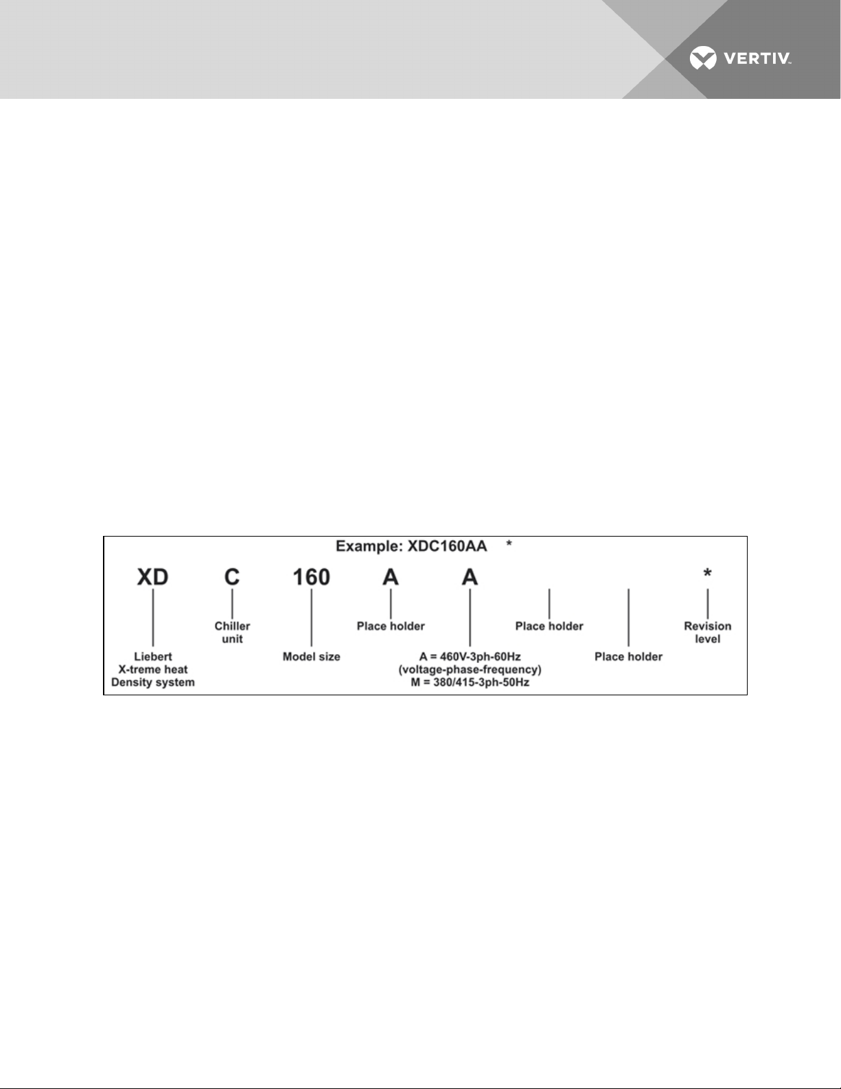
Figure 1.1 Model number nomenclature
Vertiv | Liebert® XDC™ User Manual | 7
Page 8

This page intentionally left blank.
Vertiv | Liebert® XDC™ User Manual | 8
Page 9
2 PRODUCT DESCRIPTION
2.1 General Product Information
2.1.1 Product/System Description
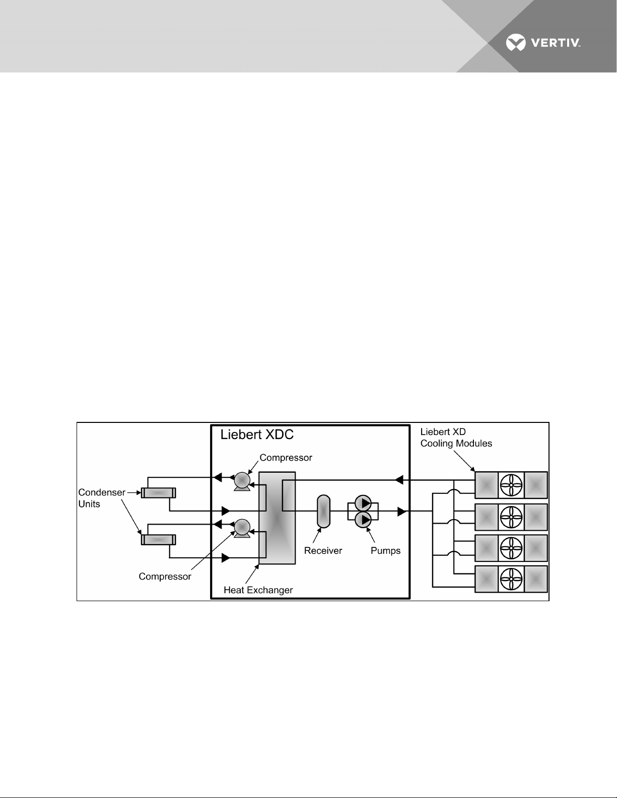
The Liebert XDC™(X-treme Density Chiller) is a self-contained refrigeration distribution unit designed to
cool rooms with high heat producing equipment. There are two distinct circuits, each utilizing different
refrigerants and mechanical parts. The R-134a circuit is the “pumped” circuit containing redundant
circulating pumps, a brazed plate heat exchanger along with valves and piping. The R-407C circuit is the
dual direct expansion circuit containing scroll compressors, expansion valves, brazed plate heat
exchanger, and piping. Heat removal is accomplished by using condensers connected to the dual direct
expansion circuit. Heat rejection is available in two options: an outdoor air-cooled condenser and a
water/glycol condenser. See Figure 2.1 below below.
The Liebert XDC monitors room conditions and prevents coil condensation by maintaining the refrigerant
being pumped to the cooling modules at a temperature above the room dew point. All functions, such as
temperature control, switching pumps (if necessary), etc., are automatic.
The Liebert XDC’s minimum recommended operating load is 40% of system nominal capacity. For
example, a Liebert XDC160 60Hz system’s minimum load would be 64kW. Loading below this value can
unfavorably affect system operation.
See Table 11.1 on page127 for the Liebert XDC160 rated cooling capacity.
Figure 2.1 Liebert XDC components
Vertiv | Liebert® XDC™ User Manual | 9
Page 10

2.2 Equipment Inspection
When the unit is delivered, inspect all items for visible and concealed damage. Damage should be
immediately reported to the carrier and a damage claim filed with a copy sent to Liebert or to your sales
representative.
NOTICE
Risk of improper storage. Can cause equipment damage.
Keep the Liebert XDC upright, indoors and protected from dampness, freezing temperatures
and contact damage.
2.3 Equipment Handling
WARNING! Risk of unit falling over. Can cause injury or death.
The Liebert XDC is top-heavy. Use extreme caution when moving and installing this unit. Use
lifting equipment that is rated for the weight of the unit by an OSHA-certified rating
organization. See Table 11.1 on page127 for unit weights. Personnel should be properly trained
and certified to move and rig equipment
CAUTION: Risk of sharp edges, splinters and exposed fasteners. Can cause personal injury.
Only properly trained personnel wearing appropriate safety headgear, gloves, shoes and
glasses should attempt to move, lift, remove packaging from or prepare the unit for installation.
2.3.1 Handling the Liebert XDC While it is on Skid and Packaged
• Always keep the unit upright, indoors and protected from damage.
• If possible, transport the unit using a forklift truck. Otherwise use a crane with slings and
spreader cables. In either case, do NOT press on the top edges of the packaging.
• If using a forklift or pallet jack, make sure the forks (if adjustable) are spread to the widest
allowable distance to still fit under the skid.
• When moving the skidded unit with a forklift, do not lift the unit any higher than 3"(76mm). If
circumstances require the unit to be lifted higher than 3"(76mm), great care must be
exercised and all by-standing personnel are to be no closer than 20 feet (6m) from the lift point
of the unit.
NOTICE
Risk of structural interference. Can cause equipment or building damage.
While on the skid, the unit is too tall (83" [2108mm] overall height) to fit through a standard
doorway. Any attempt to move the unit, while skidded, through a standard doorway will cause
damage to the unit and to the building.
NOTICE
Risk of damage from forklift. Can cause unit damage.
Keep the forklift tines level and at a height suitable to fit below the skid and/or unit to prevent
exterior and/or underside damage.
Vertiv | Liebert® XDC™ User Manual | 10
Page 11
NOTICE
Risk of improper storage. Can cause unit damage.
Keep the Liebert XDC upright, indoors and protected from dampness, freezing temperatures
and contact damage.
NOTICE
Risk of overtightening securing straps. Can cause damage to panels.
Place a protective material between the straps of the piano jacks and the unit. Ensure that the
straps are not tightened to a point of damaging panels.
2.3.2 Unpacking the Liebert XDC
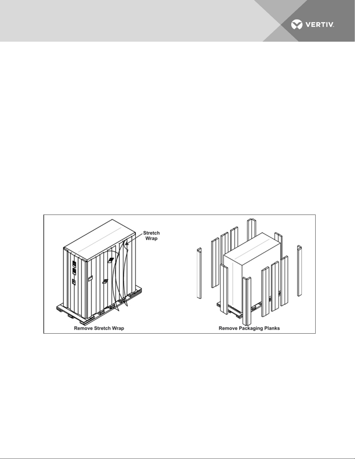
1. Remove the exterior stretch wrap packaging from the unit, exposing the protective corner and
side packaging planks.
2. Remove the corner and side packaging planks from the unit, exposing the bag over the unit.
The bag may remain in place for dust and panel protection or removed for immediate unit
installation.
3. Remove the bag from the unit when ready to remove the skid for installation.
Figure 2.2 Unpacking the Liebert XDC
2.3.3 Removing the Unit from the Skid Using a Forklift
1. Align the forklift with either the front or rear side of the unit.
Make sure the tines of the forklift are locked at their widest position.
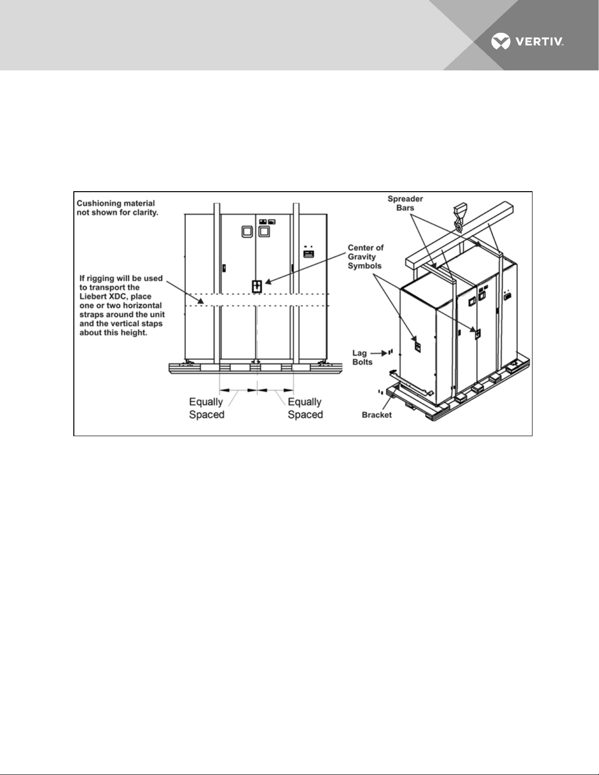
Use the center of gravity indicators to determine the entry points for the tines. The tines must
be equally spaced on either side of the center of gravity indicator (see Figure 2.3 on the next
page).
Vertiv | Liebert® XDC™ User Manual | 11
Page 12
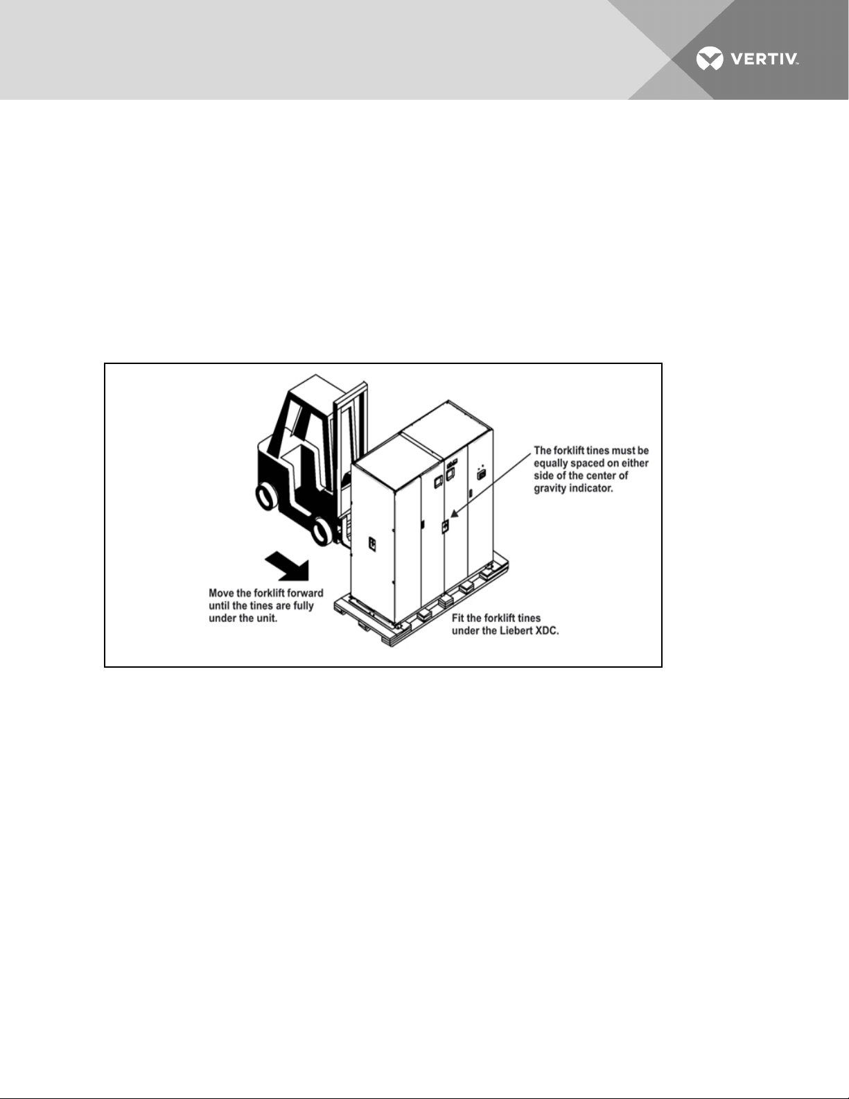
2. Insert the tines of the forklift under the unit.
Make sure the tines are level. The tines must be low enough to fit under the unit without
damaging it.
Make sure the tines extend beyond the opposite side of the unit.
3. Remove the 12 lag bolts and two brackets that secure the unit to the skid.
NOTE: Each lag bolt is 1-1/2" (38mm) long. They can be removed with a 9/16" socket or wrench.
4. Lift the unit to a height that it is not being support by the skid.
5. Move the skid from under the unit.
Figure 2.3 Use a forklift to remove the Liebert XDC from the skid
2.3.4 Removing the Unit from the Skid using Rigging
1. Use the center of gravity indicators on the unit to position the slings. The slings must be
equally spaced on either side of the center of gravity indicator (see Figure 2.4 on the facing
page).
2. Place slings under the unit using spaces provided between the skid deck boards.
NOTE: Unit is shown without outer packaging. These instructions may be applied with the outer
packaging in place.
3. Use spreader bars or an equivalent method to ensure proper protection of the unit.
4. Ensure that the panels, if attached, are well protected from the slings with cushioning material.
NOTE: If rigging is to be used to move the unit closer to the site for installation, place one or two
horizontal straps around the unit and vertical straps at mid height.
5. Remove the 12 lag bolts and two brackets that secure the unit to the skid.
NOTE: Each lag bolt is 1-1/2" (38mm) long. They can be removed with a 9/16" socket or wrench.
Vertiv | Liebert® XDC™ User Manual | 12
Page 13
6. Lift the unit off of the skid to an elevation point where the skid is not supporting the weight of
the unit.
7. Remove the skid from under the unit.
NOTE: Depending on final installation location and the method of moving the Liebert XDC, the skid may
need to remain under the unit.
Figure 2.4 Removing the unit from the skid using rigging
2.3.5 Moving the Liebert XDC Using Piano Jacks
1. Elevate the Liebert XDC with a lifting mechanism, such as a forklift or rigging.
1. Position one piano jack at each end of the Liebert XDC.
2. Lower the unit to a height suitable for placing it on the piano jacks.
3. Put protective material between the Liebert XDC and the piano jacks and straps.
4. Secure the Liebert XDC to the piano jacks.
5. Release the the Liebert XDC from the straps securing it to the lifting mechanism and move the
mechanism away from the unit.
Using the piano jacks, at least two properly trained and qualified personnel can move the unit.
Vertiv | Liebert® XDC™ User Manual | 13
Page 14
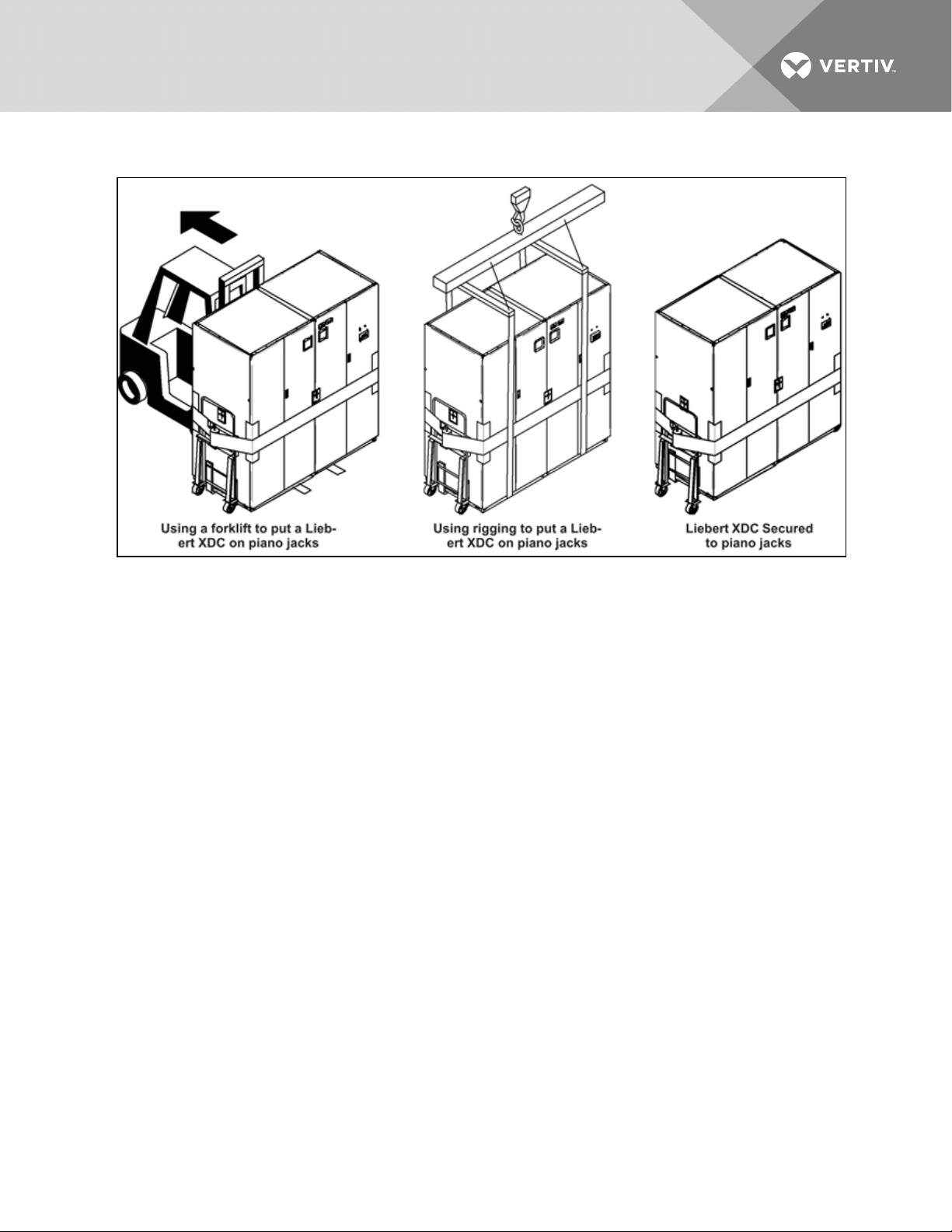
Figure 2.5 Securing the Liebert XDC to piano jacks
2.3.6 Removing the Unit from the Piano Jacks
1. Lower the Liebert XDC as far as the piano jacks will allow.
2. Undo all strapping holding the piano jacks to the unit.
3. Lift one end of the Liebert XDC off one piano jack with a pry bar or similar device, taking care
not to damage the unit’s cabinet.
4. Repeat step 3 to remove the piano jack from under the opposite end of the Liebert XDC.
5. Remove all material used to protect the unit from the piano jacks and strapping.
Vertiv | Liebert® XDC™ User Manual | 14
Page 15
3 INSTALLATION
3.1 Mechanical Considerations
3.1.1 Positioning the Liebert XDC
Install the Liebert XDC according to the site specific documentation and secure the unit to the floor.
The Liebert XDC can be installed near a wall or another Liebert XDC. However, there must be at least
3feet(92cm) clearance in front of the Liebert XDC as service access for components in the unit.
NOTE: During installation of the Liebert XDC, the top, bottom, front and left side of the unit must be
accessible.
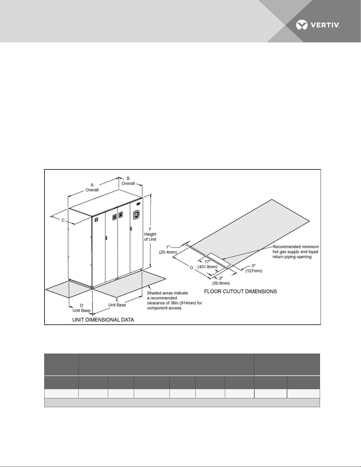
Figure 3.1 Dimensional data
Table 3.1
Liebert XDC dimensions, weight
Air-Cooled
Model
50/60Hz A B* C D E F Domestic Export
XDC160 74 (1880) 34 (864) 33-1/ 8 (841) 33 (838) 72 (1829) 78 (1981) 1975 ( 896) 2109 (957)
*Dimension does not include the bezel ofthe disconnectswitch, the handle or the control bezel.
Vertiv | Liebert® XDC™ User Manual | 15
Dimensional Data, inches (mm)
Shipping Weight
lb. (kg)
Page 16
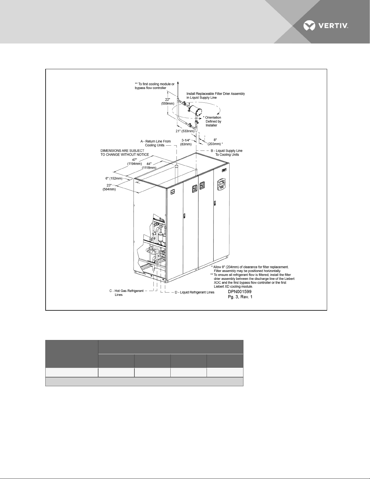
Figure 3.2 Piping locations
Table 3.2
Liebert XDC piping connection sizes
Piping Outlet Connection Sizes, OD Cu, inches
50/60Hz
A B C D
XDC160 2-1/8 1-1/8 1-3/8 7/8
Source: DPN001599
Vertiv | Liebert® XDC™ User Manual | 16
Page 17

3.1.2 Placing the Liebert XDC on a Floor Stand
WARNING! Risk of top-heavy unit falling over. Improper handling can cause equipment
damage, injury or death.
Only properly trained and qualified personnel wearing appropriate safety headgear, gloves,
shoes and glasses should attempt to move, lift, remove packaging from or prepare unit for
installation.
Read all of the following instructions before attempting to move, lift, remove packaging from or
preparing unit for installation.
The water/glycol floor stand can be located beneath the Liebert XDC unit or can be installed
nearby.
NOTE: Consult the factory if the Liebert XDC is not installed on the water/glycol condenser floor stand
to prevent exceeding the maximum piping distances.
Refer to the floor stand installation sheet shipped inside the water regulating valve package.
1. Move the floor stand assembly to its installation area and uncrate the unit.
2. Position the floor stand in its final location.
3. Insert leveler pads into each floor stand leg.
4. Level the top of the floor stand to the specified height with the flanged adjusting nut.
5. Tighten jam nuts on all legs against flanged adjusting nuts.
6. Using an appropriate lifting device or method, raise the Liebert XDC and move it above the
floor stand.
7. Align the welded tabs on top of the floor stand with the inside of the unit frame base (see Detail
A in Figure 3.3 on the next page).
8. Maintaining the alignment of the Liebert XDC and the floor stand, lower the Liebert XDC onto
the floor stand.
9. Connect the hot gas refrigerant lines from the Liebert XDC to the floor stand with 1-3/8" tubing
(see Figure 3.3 on the next page andFigure 3.4 on page20).
10. Connect the liquid refrigerant lines as shown from the Liebert XDC unit to the floor stand with
7/8" tubing (see Figure 3.3 on the next page andFigure 3.4 on page20).
11. Connect the water lines as shown with the provided valving (see Figure 3.3 on the next page
andFigure 3.4 on page20).
12. Connect capillary lines from each water regulating valve to condensers in the floor stand (see
Figure 3.3 on the next page andFigure 3.4 on page20).
Capillary length is limited to 48" (1219mm).
13. Check the pipes for leaks and evacuate air from all pipes.
14. Insulate all water/glycol lines.
15. Charge each condenser loop with R-407C (see Table 4.15 on page57).
Vertiv | Liebert® XDC™ User Manual | 17
Page 18
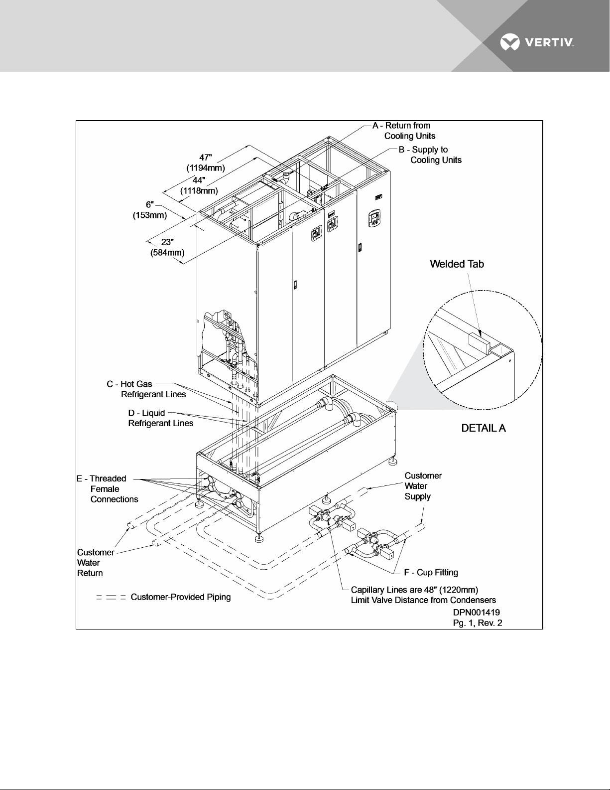
Figure 3.3 Water/glycol Liebert XDC on a floor stand—positioning and piping connections
Vertiv | Liebert® XDC™ User Manual | 18
Page 19
Table 3.3
Liebert XDC water/glycol piping connection sizes
Model Piping Outlet Connection Sizes, OD Cu, inches
50/60Hz A B C D
1
E
2
F
XDC160 2-1/8 1-1/8 1-3/8 7/8 2-1/2 2-1/8 or 2-5/8
1. Threaded female connection
2. 2-1/8" for 1" water r egulatingvalve; 2-5/8" for 1- 1/4" water regulating valve
Source: DPN00141 9 Rev. 2
Vertiv | Liebert® XDC™ User Manual | 19
Page 20
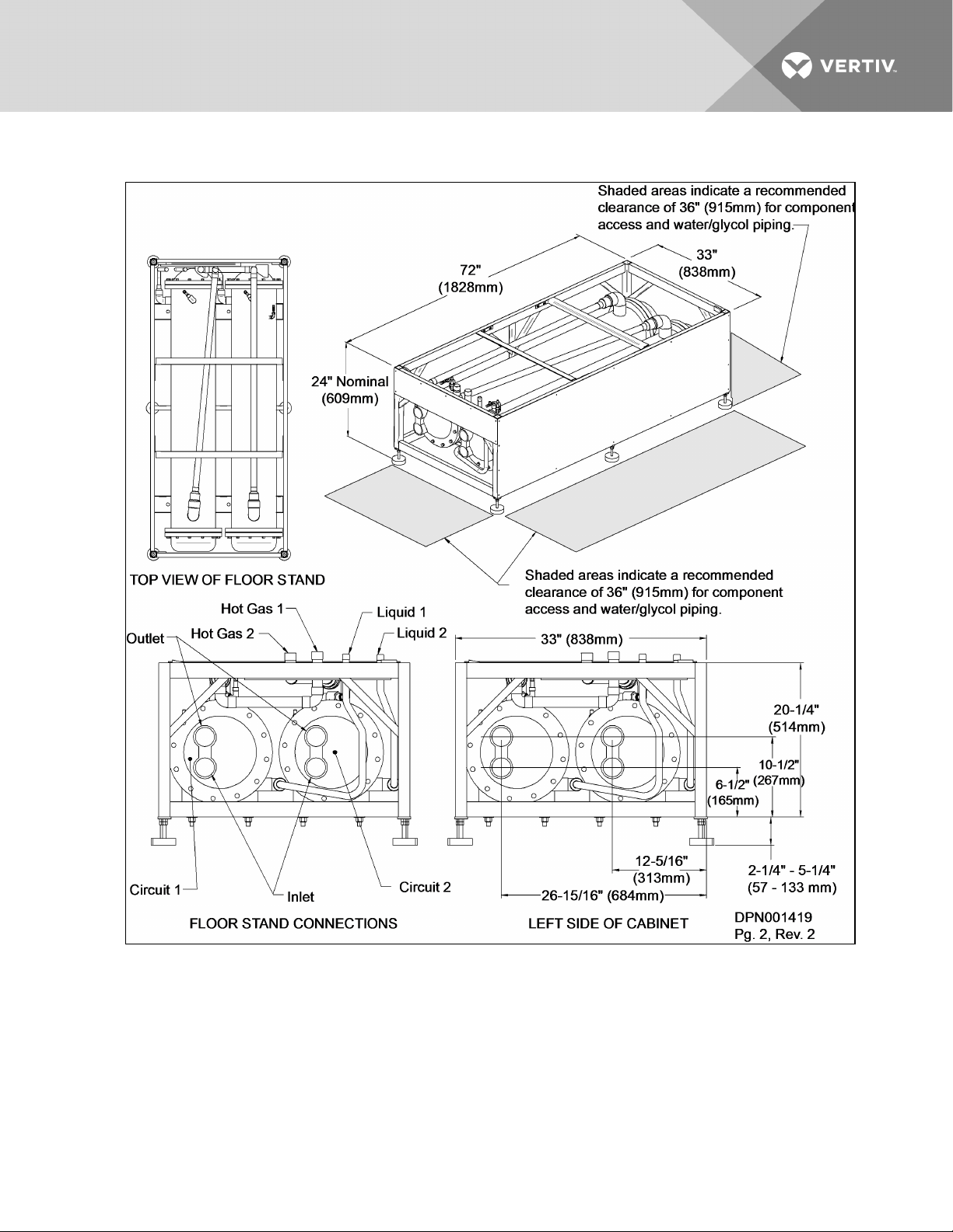
Figure 3.4 Piping locations—floor stand and valve assembly
3.1.3 Positioning the Liebert XDC with Floor Stand
Install the Liebert XDC according to the site-specific documentation and secure the unit to the floor.
The Liebert XDC can be installed near a wall or another Liebert XDC. There must be at least 3 feet
(914mm) clearance in front of the Liebert XDC for service access. When the Liebert XDC is combined with
the optional water/glycol floor stand, Vertiv recommends leaving 3 feet (914mm) of clearance on the left
side of the unit.
Vertiv | Liebert® XDC™ User Manual | 20
Page 21
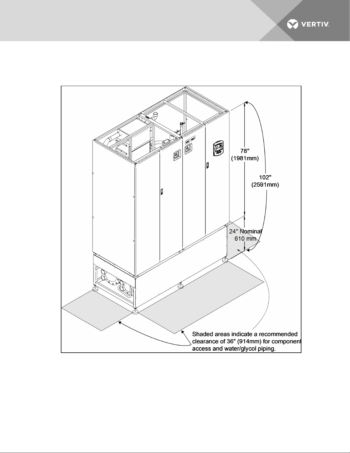
A Liebert XDC on a floor stand is 102 inches (2591 mm) high (see Figure 3.5 below). The unit can be raised
or lowered 1.5 inches (38.1 mm) with the leveling feet.
Figure 3.5 Dimensions and clearances for Liebert XDC on floor stand
Vertiv | Liebert® XDC™ User Manual | 21
Page 22

3.2 Electrical Considerations
3.2.1 High Voltage Connections
Make sure the actual supply voltage and frequency correspond to the voltage and frequency indicated
on the Liebert XDC’s rating plate.
Connect cables for high voltage supply to the electrical box in the Liebert XDC according to Figure 3.1 on
page15, Figure 3.7 on page24 and Figure 3.8 on page25 and make sure that the phases are correctly
connected.
WARNING! Risk of electric shock. Can cause death and injury.
Disconnect all local and electric remote power supplies before working within.
WARNING! Risk of electrical shock, short circuit and/or control malfunction. Can cause
equipment damage injury and death.Damage to wiring or components can make unit unsafe to
operate.Use caution when installing wiring to prevent damage to factory wiring.Install
protective bushings in wiring knockouts as required to protect wiring from sharp edges.Do not
disturb factory wiring or route field-installed wiring over electrical terminals.Use NEC Class 1
wiring for all hazardous voltage electrical power supplies.Check and retighten all wiring
connections before starting the unit.
NOTE: Before beginning to install the Liebert XDC, read all instructions, verify that all the parts are
included and check the nameplate to be sure the Liebert XDC voltage matches available utility power.
Follow all local codes.
Vertiv | Liebert® XDC™ User Manual | 22
Page 23
3.2.2 Connecting High-Voltage Cables
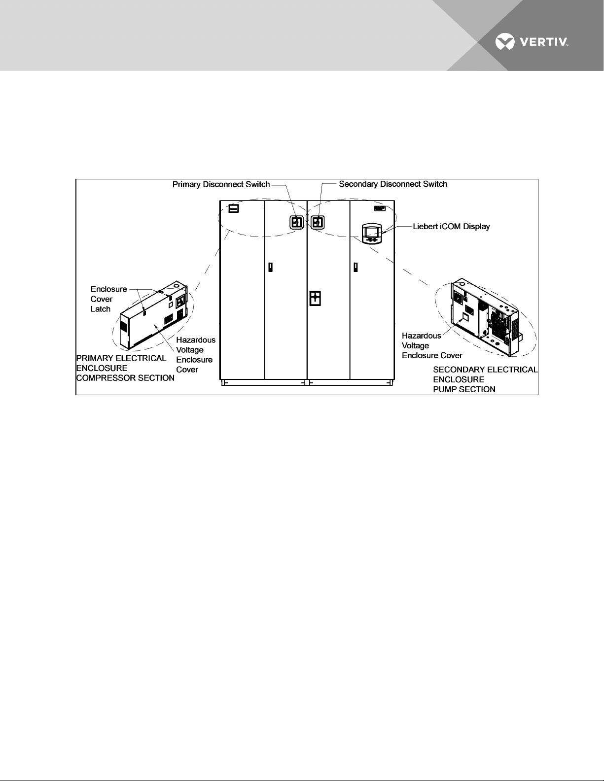
1. Turn the Liebert XDC’s primary disconnect switch to the Off position (see Figure 3.6 below).
Open the front doors and push down on the enclosure cover latch to open the hazardous
voltage enclosure cover.
Figure 3.6 Front view of Liebert XDC and electrical enclosures
Vertiv | Liebert® XDC™ User Manual | 23
Page 24
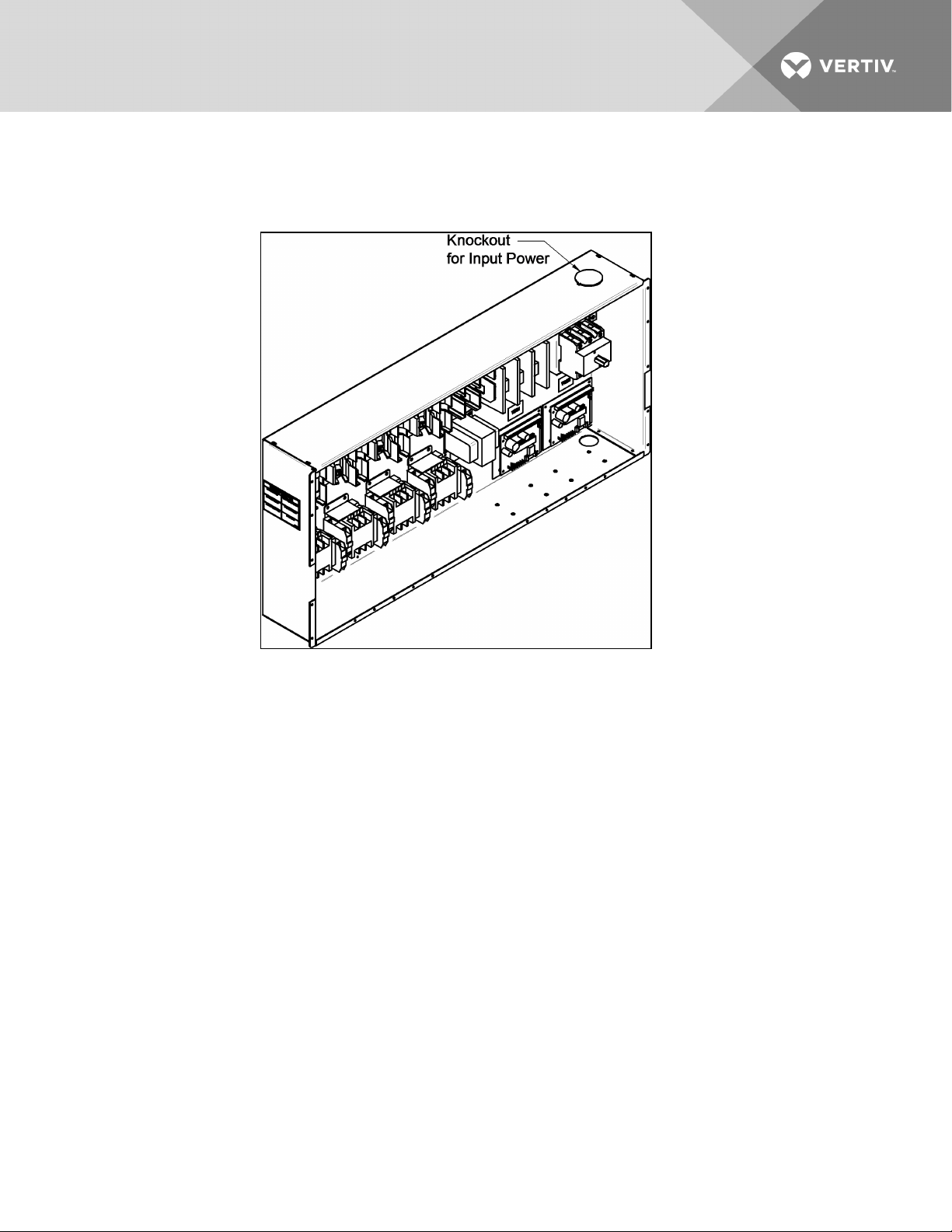
2. Determine which knockouts in the electrical enclosure will be used and remove them (see
Figure 3.7 below).
Figure 3.7 Electrical enclosure knockout locations for field wiring
Vertiv | Liebert® XDC™ User Manual | 24
Page 25
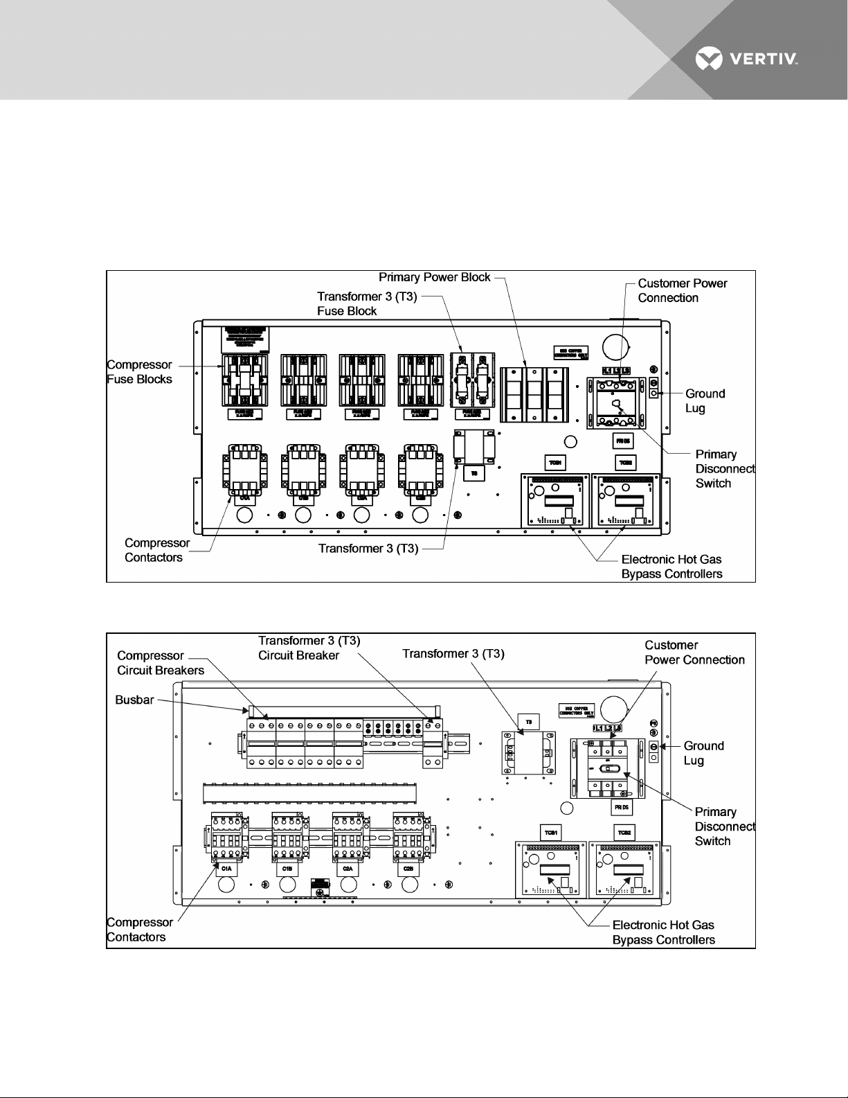
3. Route the input hazardous voltage electrical power wiring through the top right knockout on
the primary electrical enclosure (see Figure 3.7 on the previous page) to the disconnect
switch L1, L2 and L3 (see Figure 3.8 below). Observe proper phasing.
4. Connect the ground wire to the ground lug (see Figure 3.8 below andFigure 3.10 on the next
page for 60Hz models and Figure 3.9 below andFigure 3.11 on the next page for 50Hz models).
Figure 3.8 60Hz models, high voltage connections—primary disconnect switch
Figure 3.9 50Hz models high voltage connections—primary disconnect switch
Vertiv | Liebert® XDC™ User Manual | 25
Page 26
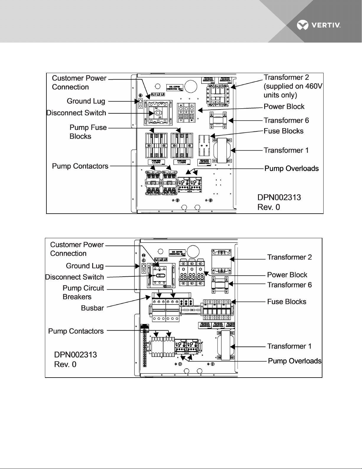
Figure 3.10 60Hz models high voltage connections—secondary disconnect switch
Figure 3.11 50Hz models high voltage connections—secondary disconnect switch
Vertiv | Liebert® XDC™ User Manual | 26
Page 27
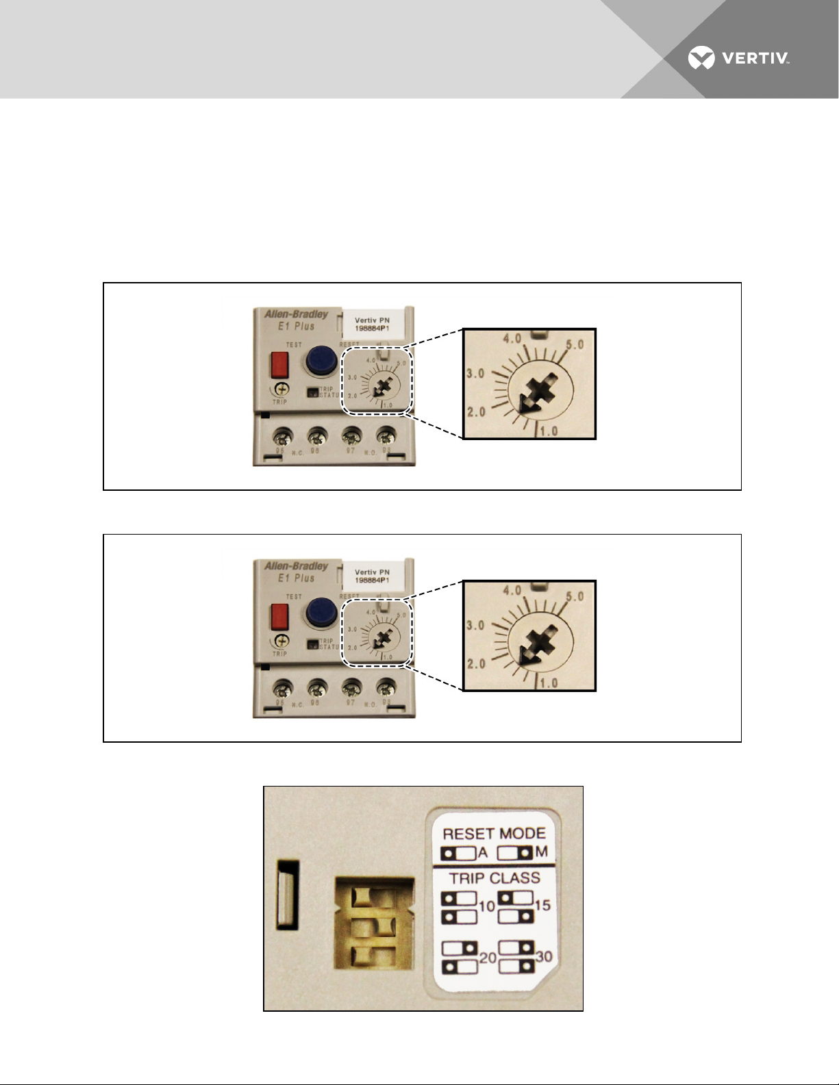
3.3 External Pump Overloads
The Liebert XDC is shipped with external pump overload with trip point settings and DIP switch settings
for normal operations. The trip points are in increments of 0.25A and should not be changed from the
factory settings. For 460V 60Hz and 380-400V 50Hz units, the trip point is set at 1.5A (Figure 3.12 below).
See Figure 3.14 below for factory DIP switch settings for normal operation with reset mode set as
automatic and Trip Class 20.
Figure 3.12 460V 60Hz and 400V 50Hz factory setting external pump overload trip point
Figure 3.13 208V factory setting external pump overload trip point
Figure 3.14 Factory DIP switch settings
Vertiv | Liebert® XDC™ User Manual | 27
Page 28
3.4 Extra Low Voltage Connections
Extra Low Voltage (ELV) power output is 30V and 100VA or less.
1. Turn off all unit power before connecting cables or wires. Failure to do so may damage this
equipment.
2. Route low voltage electrical connections through the appropriate knockouts as shown in
Figure 3.17 on page31.
3. User interface and temperature/humidity sensor wire is NEC Class 2. All electrical installation
must comply with all national, state and local requirements.
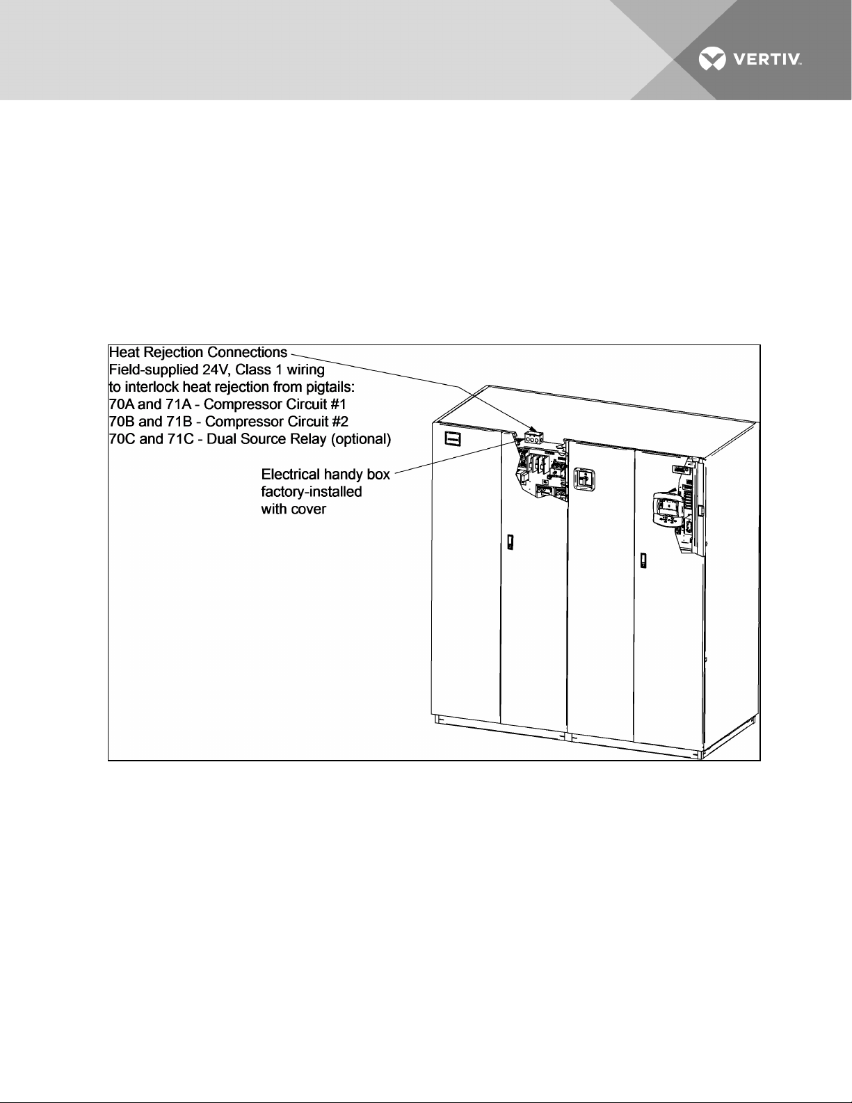
Figure 3.15 Liebert XDC heat rejection connection points
Vertiv | Liebert® XDC™ User Manual | 28
Page 29
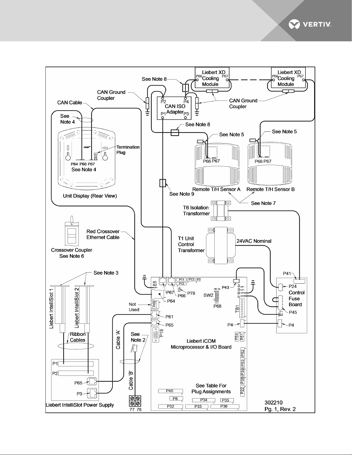
Figure 3.16 Connecting remote temperature/humidity sensors
Vertiv | Liebert® XDC™ User Manual | 29
Page 30

Notes on Figure 3.16 on the previous page
1. See unit electrical schematic, installation and user manuals.
2. Cables A and B provided with each unit. Only one is used as follows:
a. Liebert IntelliSlot-Based Communications—Cable A is pre-connected to P65 on the
microprocessor and I/O board and P65 on Liebert IntelliSlot power supply.
b. Non-Liebert IntelliSlot-Based Communications—Cable B is pre-connected to Terminals
77 & 78 but must be exchanged with Cable A at P65 on the microprocessor and I/O
board.
3. Install applicable Liebert IntelliSlot cards.
4. Both cables (P64 and P66) are required.
5. It is not necessary to connect ground coupling on end of cable connected to Sensor A or B.
6. A crossover coupler is provided for unit-to-unit (U2U) networking. Unplug the red cable from
P64 on the microprocessor and I/O board and connect to one side of the crossover coupler.
The first customer connection point is to P64 on the microprocessor and I/O board. The
second customer connection point is to the other side of the crossover coupler. This connects
the microprocessor and I/O board and display to the private U2U network.
7. The remote sensors are interchangeable as to which connects to the Liebert XD cooling
module and which connects to P2 on CAN ISO.
8. Field-install cables with factory-installed ferrite beads (when provided, typical two places).
Each cable must make three passes through the ferrite bead. Locate the ferrite bead on top of
the electric box. See instruction sheet provided with the cable assembly.
9. Factory-installed ferrite bead (when provided). Cable passes through ferrite bead three times.
Vertiv | Liebert® XDC™ User Manual | 30
Page 31

Figure 3.17 Electrical enclosure knockout locations for Extra Low Voltage connections
Field Connections—All Units
• Place Sensor A in the higher-temperature portion of the cold aisle where the Liebert XD
modules are located. Alternatively, it may be placed on the return air side of the primary air
mover (e.g., Liebert DS™) in the room if it represents the conditions where all the Liebert XD
cooling modules are located. Do not install the sensor where ambient air might cause false
readings, for example, near unsealed doors, windows and similar areas.
1. Unpack the two remote temperature/humidity sensors and cables.
One sensor is labeled Sensor A and the other, Sensor B. The sensor cables are interchangeable;
each bears labels indicating Sensor End and Unit End.
2. Connect the Sensor End of one of the supplied sensor cables to P66 on Sensor A (see Figure
3.16 on page29).
3. Connect the Unit End of the sensor cable to P4 on the CAN Isolator inside the Liebert XDC (see
Figure 3.16 on page29). Secure the terminal plug on the cable shield to the into the terminal
plug adjacent to P2 (see Figure 3.16 on page29).
4. Connect the Sensor End of the second sensor cable to P66 on Sensor B (see Figure 3.16 on
page29).
5. Connect the Unit End of the cable to P4 on the CAN Isolator inside the Liebert XDC (see Figure
3.16 on page29). Secure the terminal plug on the cable shield to the terminal plug adjacent to
P4 (see Figure 3.16 on page29).
Vertiv | Liebert® XDC™ User Manual | 31
Page 32

Field Connections—Optional for All Units
• Connect optional field wiring from remote devices to Remote Alarm Device, Common Alarm
Output, IGM and Remote Shutdown, if applicable. See terminal strip descriptions in Figure 3.18
on the facing page.
Field Connections—Air-Cooled Units only
Connect field wiring to heat rejection connection terminals on the handy box as shown in Figure 3.15 on
page28.
Vertiv | Liebert® XDC™ User Manual | 32
Page 33

Figure 3.18 Extra Low Voltage field connection points
Vertiv | Liebert® XDC™ User Manual | 33
Page 34

DIP Switch and Jumper Settings for remote sensors
The Liebert XDC is shipped with jumpers and DIP switch settings for normal operations. See Figure 3.19
below.
Figure 3.19 DIP switch and jumper settings for remote sensors
3.5 Remote Sensor Installation—Proper Placement
Placement of the two remote temperature/humidity sensors is critical to effective cooling of the
conditioned space.
The remote sensors must be installed in areas where conditions are representative of the space
conditioned by the Liebert XDC. Vertiv recommends installing the sensors in different areas near the
cooling modules served by the Liebert XDC. If the return air side of the primary air mover, such as a
Liebert DS, represents the conditions where the Liebert XD cooling modules are located, one sensor could
be placed there. Vertiv suggests placing the other sensor on the wall opposite the heat load area (see
Figure 3.20 on the facing page for guidance).
Vertiv | Liebert® XDC™ User Manual | 34
Page 35

Figure 3.20 Suggested remote sensor placement
Do not install the sensors where ambient air might cause false readings, for example, near unsealed doors
or windows, or areas with stagnant air.
Vertiv | Liebert® XDC™ User Manual | 35
Page 36

This page intentionally left blank.
Vertiv | Liebert® XDC™ User Manual | 36
Page 37

4 PIPING AND FILLING WITH REFRIGERANT: R-134A AND R-407C CIRCUITS
4.1 European Union Fluorinated Greenhouse Gas Requirements
Stationary air conditioning, refrigeration, heat pump equipments and stationary fire protection systems in
the European Community market and operating with fluorinated greenhouse gases (f-gas), such as
R407C, R134a, R410A, must comply with the F-Gas Regulation: (EC) No. 842/2006 (F-gas). The regulation
prohibits, among other actions, venting fluorinated greenhouse gases to the atmosphere.
The F-Gas Regulation requires operators to use all measures that are technically feasible and do not
entail disproportionate cost to prevent leakage of these gases, to test for leakage regularly and to recover
f-gas before disposing of equipment, as well as during service and maintenance.
Refer to the full regulation for additional details.
4.2 Recommended Pipe Size
NOTE: Follow all local codes on maximum length and size of refrigerant lines.
Connect the main pipes between the Liebert XDC and the Liebert XD cooling modules according to site
specific documentation and the configuration guide for the Liebert XD system.
Elbows and restrictions shall be minimized for proper operation.
Table 4.1
Supply, return pipe sizes for Liebert XD refrigerant loop
Pipe Function Size/Equivalent Pipe Length
Liebert XDC s upply line, from Liebert XDC
supply to far thest Liebert XD cooling module
Liebert XDC r eturn line, from farthest coolingmodule to Liebert
XDC return
From any model Liebert XDO/ Liebert XDH supply to supply line
of L iebert XDC
From any model Liebert XDO/ Liebert XDH return to r eturn line
of L iebert XDC
From any model Liebert XDV/Liebert XDCF supply to s upply line
of L iebert XDC
From any model Liebert XDV/Liebert XDCF return toreturn line
of L iebert XDC
1-1/8" OD (1.025" ID) for lengths up to 60 feet
1-3/8" OD (1.265" ID) for lengths over 60 butless than175 feet
2-1/8" OD (1.985" ID) for lengths upto 60 feet
2-5/8" OD (2.465" ID) for lengths over 60 but less than 175 feet
1/2" OD (0.4 30" ID) for lengths up to 10 feet
7/8" OD (0.785" ID) for lengths over 10 but less than 25 feet
7/8" OD (0.785" ID) for lengths upto 10 feet
1-1/8" OD (1.025" ID) for lengths over 10 but less than 25 feet
1/2" OD (0.4 30" ID) for lengths up to 10 feet
5/8" OD (0.545" ID) for lengths over 10 butless than35
5/8" OD (0.545" ID) for lengths upto 10 feet
7/8" OD (0.785" ID) for lengths over 10 but less than 35 feet
Vertiv | Liebert® XDC™ User Manual | 37
Page 38

4.3 Liebert XDC Interconnection With Liebert XD Cooling Module
All piping must be ASTM (American Society for Testing and Materials) Type ACR copper pipe.
The Liebert XDC may be connected to Liebert XD cooling modules with either Liebert’s XD prefabricated
piping assembly or with rigid, off-the-shelf piping. In either setup, piping for the Liebert XD system is
arranged in a manner similar to piping for a chilled water system. Liebert XD cooling modules are
connected in parallel between main return and supply pipes going to and from the Liebert XDP/Liebert
XDC. Figure 4.1 below represents a typical configuration. For piping details, refer to Liebert’s XD System
Design Manual, SL-16655. The guidelines provided for pipe size must be strictly followed. Failure to size
the main lines and connection lines adequately may result in reduced cooling capacity. The critical
aspects of pipe sizing are related to refrigerant volume and pressure drop. Both must be minimized.
Figure 4.1 Liebert XD system diagram
4.4 Piping Installation Method
The assembly and connection means used for piping in the Liebert XD system are similar to those used
for conventional refrigeration systems. All piping should be installed with high-temperature brazed joints.
Soft soldering is not recommended.
During brazing, the lines must be filled with flowing dry nitrogen to prevent excessive oxidation and scale
formation inside the piping. Prevailing good refrigeration practices must be employed for piping supports,
leak testing, dehydration and charging. Failure to use good system practices may result in damage to the
system. Refer to the ASHRAE refrigeration handbook for general good-practice refrigeration piping.
Insulate all piping lines to prevent condensation in applications where the dew point approaches the
R-134a refrigerant temperature.
Vertiv recommends venting the pressure relief valves for both the R-134a and R-407C sides outside the
conditioned space where it is open to the atmosphere. The R-134a side relief valve is inside the Liebert
XDC unit at the top of the receiver. The R-407C water/glycol-cooled side relief valves are located at each
condenser beneath the Liebert XDC unit in the floor stand. The R-407C air-cooled relief valves are
located outside within the air-cooled system.
Vertiv | Liebert® XDC™ User Manual | 38
Page 39

4.4.1 Piping Installation—R-134a Pumped Circuit
Vertiv recommends venting the relief pressure of the Liebert XDC (located at the top of the receiver)
outside of the conditioned space where it is open to the atmosphere.
4.4.2 Bypass Flow Controllers
Two bypass flow controllers are required to ensure the Liebert XDC pumps operate within the optimum
range. These devices are added to the field piping and simulate the flow of additional cooling modules.
Each bypass flow controller must be installed with one shutoff valve to allow the controller to be disabled
when cooling modules are added to a Liebert XD system.
Bypass flow controllers should be connected between the main supply and the main return lines of the
field piping. The connection points to the main supply and return lines should be in a convenient and
accessible location between the Liebert XDP/Liebert XDC and the first Liebert XD module in the circuit.
See Figure 4.2 below andFigure 4.3 on the next page for piping details of the bypass flow controller.
Refer to Table 4.2 below to determine the number of bypass flow controllers needed to be open to
provide proper refrigerant flow, based on the total nominal cooling capacity of the cooling modules in
each Liebert XD system.
Table 4.2
Bypass flow controllers for a Liebert XDC-based system
Required Number of Open
System Load kW
Cumulative Module Model Size
32 to 63 N/A
64 to 95 2
96to 127 1
128 to 1 60 0
Bypass Flow Controllers
Liebert XDC
Figure 4.2 Bypass flow controller details, dimensions
Vertiv | Liebert® XDC™ User Manual | 39
Page 40

Figure 4.3 Bypass flow controller arrangement
Figure 4.4 Bypass flow controller piping
Vertiv | Liebert® XDC™ User Manual | 40
Page 41

4.5 Piping Details—Shutoff/Isolation Valves
Isolation valves must be installed on the Liebert XDC’s refigerant circuit to permit maintenance on the
unit (see Figure 4.5 below.)
Figure 4.5 General piping details
Evacuation and Leak Check—R-134a Pumped Circuit
1. Open all service valves, including those located outside of the Liebert XDC.
2. Attach a jumper hose from one of the Schrader valve fittings on a pump outlet before the
check valve to a Schrader valve fittings after the check valve.
3. Place 150 psig (1034kPa: 10.34 bars) of dry nitrogen with a tracer of R-134a in the system.
NOTE: Risk of overpressurization. Can cause equipment damage.
Do not exceed 150 psig (1034 kPa; 10.34 bars) in the R-134a circuit.
4. Check the system for leaks with a suitable leak finder on the pumps’ suctions lines.
5. After completion of the leak testing, release the test pressure (per local code) and connect to
vacuum pump(s) at the Schrader valves.
6. After four hours of pulling a deep vacuum, check the vacuum level and if it has not changed,
break the vacuum with dry nitrogen.
7. Pull a second vacuum to 500 microns or less. Recheck the vacuum level after 2 hours.
Insulation
NOTE: Piping should not be insulated before it has been checked for leaks. Applying good insulation
to pipes before checking for leaks would prevent easy detection of leaks.
Insulate all piping between the Liebert XDC and cooling modules to prevent condensation where the
piping passes through non-conditioned areas.
4.6 Filling the Pumped Circuit—R-134a
1. Connect a charging manifold to the Schrader valve fittings on the pump suctions lines.
Vertiv | Liebert® XDC™ User Manual | 41
Page 42

2. Purge the hoses.
3. Calculate the amount of R-134a refrigerant needed to charge the system, using the values in
Table 4.3 below, Table 4.4 below, Table 4.5 on the facing page and Table 4.6 on the facing
page; for assistance, refer to Calculating Refrigerant Charge—Example on page44. The
section includes a worksheet to calculate system refrigerant charge requirements.
4. Weigh in the calculated charge.
5. After adding the calculated charge, allow the system to sit 15 to 30 minutes to reach
equilibrium. Observe the refrigerant level through the sight glasses of the receiver.
6. If the refrigerant level is improper, the charge must be adjusted.
If the level is too high or too low, recalculate the required charge and reduce or increase the
amount as needed to reach the proper level.
NOTE: All lengths in Table 4.4 below, Table 4.5 on the facing page and Table 4.6 on the facing page
are actual pipe lengths, not equivalent pipe lengths.
NOTE: System refrigerant volume calculations derived from Table 4.3 below, Table 4.4 below, Table
4.5 on the facing page and Table 4.6 on the facing page are based on a fully loaded system.
Additional charge may be required for lightly loaded systems.
Table 4.3
System R-134a charge for a Liebert XDC with any model Liebert
XDH/Liebert XDO/Liebert XDV/Liebert XDCF
Refrigerant Charge,
lb. (kg)
157 lb. (65.7kg) Liebert XDC
3.55 lb. ( 1.61kg) Liebert XDO
2.32 lb. (1.05kg) Liebert XDV
5.32 lb. ( 2.41 kg) Liebert XDH
1.41 lb. (0.64kg) Liebert XDCF
4.0 lb. (1 .81kg) Liebert XDR
Per Liebert XD Unit
(Excludes Connector Lines
to and from Liebert XD Cooling Module)
Table 4.4
System refrigerant charge for the supply and return mains
Refrigerant Charge,
lb/foot (kg/m)
0.45 (0.67) Main supply actual lengthper 1-1/8" OD copper tubing
0.68 (1.01) Main supply actual lengthper 1-3/8" OD copper tubing
0.28 (0.42) Main return actual lengthper 2-1/8" OD copper tubing
0.43 (0.64) Main return actual lengthper 2-5/8" OD copper tubing
Supply/Return Main Length and Diameter
Vertiv | Liebert® XDC™ User Manual | 42
Page 43

Table 4.5
R-134a refrigerant charge for hard-piped connector lines to and from any model Liebert XDH/Liebert
XDO/Liebert XDV/Liebert XDCF
Refrigerant Charge,
lb/foot (kg/m)
0.08 (0.12) 1/2" OD Liebert XDO/L iebert XDH/Liebert XDV/Liebert XDCF/Liebert XDR supply connector actuallength
0.13 (0.19) 5/8" OD copper tubing Liebert XDV/Liebert XDCF supply connector actual length
0.26 ( 0.39) 7/8" OD L iebert XDO/Liebert XDH/Liebert XDR supply connector actual length
0.02 (0.03) 5/8" OD copper tubing Liebert XDV/Liebert XDCF return connector actual length
0.04 (0.06) 7/8" OD copper tubingLiebert XDV/Liebert XDCF return connector actual length
0.04 (0.06) 7/8" OD copper tubingLiebert XDH/Liebert XDO/Liebert XDR return connector actual length
0.07 (0.1) 1-1/8" OD copper tubing Liebert XDH/Liebert XDO/Liebert XD R return connector actual length
Hard-Piped Connector Length and Diameter
Table 4.6
R-134a refrigerant charge for Liebert XD Flex Pipe connector lines to and from any model Liebert
XDO/Liebert XDH/Liebert XDV/Liebert XDCF
Refrigerant
Charge, lb. (kg)
Supply Line Diameter 1/2"
0.3 lb. (0.14) 4 ft. Liebert XD Flex Pipe L iebert XDH/Liebert XDO/Liebert XDV/Liebert XDCF/Liebert XDR s upply
0.5 lb. (0.23) 6 ft. Liebert XD Flex Pipe L iebert XDH/Liebert XDO/Liebert XDV/Liebert XDCF/Liebert XDR s upply
0.7 lb. (0.32) 8 ft. Liebert XD Flex Pipe Liebert XDH/Liebert XDO/L iebert XDV/L iebert XDCF/Liebert XDR supply
0.8 lb. ( 0.36) 10 ft. Liebert XD Flex Pipe Liebert XDH/Liebert XDO/Liebert XDV/L iebert XDCF/Liebert XDR supply
Return Line Diameter 5/8"
0.01 lb. (0.01) 4 ft. Liebert XD Flex Pipe existing Liebert XDV sys tems
0.02 lb. (0.01) 6 ft. Liebert XD Flex Pipe existingLiebert XDV systems
0.03 lb. (0.01) 8 ft. Liebert XD Flex Pipe existing Liebert XDV sys tems
0.03 lb. (0.01) 1 0 ft. Liebert XD Flex Pipe existingLiebert XDV systems
Return Line Diameter 1"
0.13 lb. (0.06) 4ft L iebert XD Flex Pipe Liebert XDH/L iebert XDO/Liebert XDV/Liebert XDCF/Liebert XDR supply
0.2 lb. (0.096) 6ft Liebert XD Flex Pipe Liebert XDH/Liebert XDO/Liebert XDV/L iebert XDCF/Liebert XDR supply
0.27 lb. (0.126) 8ftLiebert XD Flex Pipe L iebert XDH/Liebert XDO/Liebert XDV/Liebert XDCF/Liebert XDR s upply
0.33 lb. (0.15) 10ft L iebert XD Flex Pipe Liebert XDH/Liebert XDO/Liebert XDV/L iebert XDCF/Liebert XDR supply
Metal L iebert XD Flex Pipe Connector L ength
Vertiv | Liebert® XDC™ User Manual | 43
Page 44

4.6.1 Calculating Refrigerant Charge—Example
Using Table 4.3 on page42,Table 4.4 on page42,Table 4.5 on the previous page andTable 4.6 on the
previous page, calculate the refrigerant charge of the individual sections of your Liebert XD system. Add
the calculated charge amounts to determine the amount of R-134a refrigerant required for one system
combining a Liebert XDC with Liebert XD cooling modules (Liebert XD CoolFrame, Liebert XDH, Liebert
XDO and Liebert XDV). The example below combines one Liebert XDC with 20 Liebert XDV8 cooling
modules.
Table 4.7
Calculating refrigerant charge—example
Components
Liebert XDC 1 157 157
Liebert XDV8 Cooling Modules 20 2.32 46.4
Supply Main, 1-1/8" 100 0.45 45
Return Main, 2-1/8" 100 0.28 28
Liebert XDV 1 /2" supply Liebert XD Flex Pipes 20 0.8 16
Liebert XDV 5/8" return Liebert XD Flex Pipes 20 0.03 0.6
Number ofUnits
or Piping Length, feet
Pounds
Per Component
Total 293
Table 4.8
Worksheet to calculate refrigerant charge
Components
Number ofUnits
or Piping Length
Pounds
Per Component
Total, lb.
Total
Total
Vertiv | Liebert® XDC™ User Manual | 44
Page 45

4.6.2 Piping for Direct Expansion (DX) Circuit—R-407C Air-Cooled Units
WARNING! Risk of refrigerant system explosion or rupture from overpressurization. Can cause
equipment damage, injury or death.
Installer must install a 400 psig pressure relief valve in each of the two R-407C refrigerant
circuits of the Liebert XDC system. Do not install shutoff valves between the compressors and
the pressure relief valves.
For systems requiring EU CE compliance, the pressure relief valves must be CE-certified by a
notified body to the EU Pressure Equipment Directive.
4.7 Install Double Discharge Risers
For air-cooled systems, double discharge risers must be installed in the hot gas lines that have vertical
heights of 15 feet (4.6m) or more (see Figure 4.6 below). This will allow proper oil return to the
compressors when the system is running at low loads. A double riser system is constructed of a large
diameter riser with a trap at the base and a riser with a smaller diameter in parallel.
At full-load operation, the refrigerant vapor flows up both risers at velocities that are adequate to carry
the oil. At low loads, refrigerant vapor velocities are lower and the trap at the bottom of the riser becomes
filled with oil. When this happens, refrigerant flows up only the smaller riser.
The trap at the top of the riser must be tied into the top of the line to prevent oil from filling the larger
riser. For each double riser used, the maximum height of the riser must not exceed 15 feet (4.6m). Multiple
risers must be installed in series as the height of the hot gas line increases. Total maximum height of the
hot gas line must not exceed 60 feet (18.3m).
Horizontal discharge lines should be pitched downward in the direction of flow to aid in oil drainage with
downward pitch of at least 1/2 inch in 10 feet (13mm in 3m).
Figure 4.6 Double discharge riser layout
Vertiv | Liebert® XDC™ User Manual | 45
Page 46

Contact your local Liebert representative for factory approval whenever a refrigerant piping run exceeds
200 feet (60m) equivalent length or when condensers must be installed below the level of the cooling coil.
For Air-Cooled Liebert Lee-Temp / Flood Back Head Pressure Control Units Only
WARNING! Risk of explosive discharge from high-pressure refrigerant. Can cause injury or
death.
This unit contains fluids and/or gases under high pressure.
Relieve pressure before working with piping.
NOTICE
Risk of refrigerant contamination. Can cause equipment damage and operational problems.
Refrigerant R-407C is a blend of three components and must be introduced and charged from
the cylinder only as a liquid.
Refrigerant R-407C uses a POE (polyolester) lubricant. Do not open the compressor unit
piping to the atmosphere for more than 15 minutes. The compressors contain POE oil that is
very hygroscopic; it quickly absorbs water from the atmosphere. The longer the compressor
piping is open to the atmosphere, the harder it will be to fully evacuate. If left open too long, the
POE oil may need to be replaced before achieving the required vacuum level.
POE oils also have a property that makes them act as a solvent in a refrigeration system.
Maintaining system cleanliness is extremely important because the oil will tend to bring any
foreign matter back to the compressor. Refer to the ASHRAE refrigeration handbook for
general good-practice refrigeration piping.
Table 4.9
Receivers and head pressure kits for Liebert Lee-Temp condensers
Outdoor Ambient
°F (°C)
-30 to 100 (- 34 to 38) DCSL415 2
-30 to 105 (-34 to41) DCSL616 2
35 to 105 (2 to 41) D CSL616 2
1. 120V heater
2. 230V heater
Condenser
Model 50/60Hz
Condenser
Qty
Receiver
Part #
185010G21/G4
179713G11/G2
181610G21/G4
Receiver
Qty
2
2 179711 G1 2
2
1 179711G2 2
2
2 179711 G1 2
Head
Pressure Kit
Head
Pressure
Kit Qty
Vertiv | Liebert® XDC™ User Manual | 46
Page 47

Figure 4.7 Installation data—Liebert Lee-Temp, one-circuit, four-fan model
Vertiv | Liebert® XDC™ User Manual | 47
Page 48

Figure 4.8 Installation data—Liebert Lee-Temp, one-circuit, high ambient six-fan model
Vertiv | Liebert® XDC™ User Manual | 48
Page 49

Figure 4.9 Liebert XDC piping schematic and Liebert Lee-Temp heater pad wiring
Vertiv | Liebert® XDC™ User Manual | 49
Page 50

Figure 4.10 General arrangement air-cooled Liebert XDC Liebert Lee-Temp Control
Vertiv | Liebert® XDC™ User Manual | 50
Page 51

Table 4.10
Recommended refrigerant line sizes, DX R-407C, OD copper
Liebert XDC 160
Equivalent
Length, ft., (m)
50 (15) 1-1/8 7/8
100 (30) 1-1/8 1-1/8
150 (45) 1-3/8 1- 1/8
200 (60) 1-3/8 1- 1/8
* Double risers are required when hot gas vertical rise is 1 5ft. (4.6m) or more (see Install Double Discharge Risers on page45).
Source: DPN000937, Pg. 3, Rev. 11
*Hot Gas Line, in. Liquid Line,in.
Vertiv | Liebert® XDC™ User Manual | 51
Page 52

Figure 4.11 DCSL616 piping connections—two refrigerant circuits connected for parallel flow
Vertiv | Liebert® XDC™ User Manual | 52
Page 53

Table 4.11
Recommended refrigerant line sizes for DCSL616
Liebert XDC 160
Equivalent
Length, ft., (m)
50 (15) 1-1/8 7/8
100 (30) 1-1/8 1-1/8
150 (45) 1-3/8 1-1/8
200 (60) 1-3/8 1-1/8
* Double risers are required when hot gas vertical rise is 1 5 feetor more (see Install Double Discharge Risers on page45).
Source: DPN000937, Pg. 4, Rev. 11
*Hot Gas Line, in. Liquid Line, in.
Figure 4.12 DCSL616 piping connections—two refrigerant circuits connected for parallel refrigerant
flow
Vertiv | Liebert® XDC™ User Manual | 53
Page 54

4.7.1 Air-Cooled Condenser with Liebert Lee-Temp “Flooded Condenser” Head Pressure Control System—R-407C (DX) Circuit
The Liebert Lee-Temp system consists of a modulating type head pressure control valves and insulated
receivers with heater pads to ensure operation at ambient temperatures as low as -30°F (-34.4°C).
Liebert Lee-Temp Piping
Two discharge lines and two liquid lines must be field-installed between the indoor unit and the outdoor
condenser. See 4.6.2 on page45 and 4.6.2 on page45 for details.
Liebert Lee-Temp Control Materials Supplied
• Built-in, pre-wired condenser control box
• Air-cooled condenser
• Piping access cover to be reinstalled when piping is complete
• Bolts—four per leg (3/8" x 5/8")
• Terminal block for two-wire, 24V interlock connection between unit and condenser
• Condensate legs—four with one-fan, six on two-and three-fan models and eight on four-fan
models
• Bolts—used to mount receiver (3/8" x 1-1/4")
• Liebert Lee-Temp system:
• Insulated storage receiver—one per circuit
• Head pressure control assembly (head pressure valves and check valves) - one per
circuit
• Service valve—one per circuit
• Pressure relief valve—one per circuit
• Liquid level sight glasses
NOTE: Liebert Lee-Temp heater pads require a separate, continuous electrical source. See nameplate
on unit for proper voltage.
Evacuation and Leak Check—R-407C (DX) Circuit (Air and Water/Glycol Systems)
1. If unit power is available, open the unit’s liquid line and hot gas valve solenoid valves using the
Tandem Bank 1 and Tandem Bank 2 evacuation function in the Liebert iCOM’s Service Menu. If
power is not available to the unit, a field-supplied 24VAC/75VA power source must be directly
connected to each of the unit’s solenoid valves..
NOTE: The procedures above allow the technician to use 24VAC power and controls to open liquid line
solenoid valve(s) for the dehydration process. If no power is at the unit disconnect, the technician is to
use a separate 24VAC source rated at 75 VA and connect to the system liquid line solenoid valve(s)
directly.
2. Attach refrigerant gauges to the suction and discharge service valves of the compressor.
3. Open all compressor service valves, including those located outside the Liebert XDC.
4. Connect the tank of dry nitrogen to the Schrader valves on the liquid lines and the hot gas
lines.
5. Pressurize the system circuit(s) to 150 PSIG (1034 kPa; 10.34 bars) with dry nitrogen with a
trace of refrigerant. Check the system for leaks with a suitable leak finder.
Vertiv | Liebert® XDC™ User Manual | 54
Page 55

6. After completion of leak testing, release the test pressure (per local code) and connect to
vacuum pump(s) at the Schrader valves on the liquid lines and on the hot gas lines.
NOTE: There is a check valve in the discharge line and Liebert Lee-Temp piping assembly of each
circuit. Ensure that all pressure has been relieved before starting the vacuum pump.
7. Place a jumper hose from the service valve fitting on the outlet of the receiver and the
schrader fitting on the discharge header of the condenser. Front-seat the service valve two (2)
turns.
8. After 4 hours of pulling a deep vacuum, check the vacuum levels and, if they have not
changed, break the vacuum with dry nitrogen.
9. Pull a second and third vacuum to 500 microns or less. Recheck the vacuum level after 2 hours.
10. Once a system has achieved 500 microns, turn off evacuation, close the receiver service valve
and remove the jumper hose.
4.8 Filling the Direct Expansion (DX) Circuit—R-407C
NOTE: If necessary, refer to Installation Checklist on page59 to ensure that the system has been
properly checked out and is ready to be filled with refrigerant.
Any recommended volumes will be approximate. The user must verify that all circuits of the system
have been adequately filled.
For Air-Cooled Liebert Lee-Temp / Flood Back Head Pressure Control Units Only
NOTE: Proper safety equipment and proper refrigeration tools are required. Check unit nameplate for
correct refrigerant type before topping off or recharging a system.
NOTE: Refrigerant R-407C is a blend of three components, and must be introduced and charged from
the cylinder only as a liquid.
Refrigerant R-407C uses a POE (polyolester) lubricant. Do not open the compressor unit piping to the
atmosphere for more than 15 minutes. The compressors contain POE oil that is very hygroscopic; it
quickly absorbs water from the atmosphere. The longer the compressor piping is left open to the
atmosphere, the harder it will be to fully evacuate. If left open too long, the POE oil may need to be
replaced before achieving the required vacuum level.
Refrigerant charging requires unit operation. Refer to Checklist for Liebert XDC Startup on page111.
1. Calculate the amount of charge for the R-407C side of the system. Refer to Table 4.13 on the
next page, Table 4.14 on the next page, Table 4.15 on page57 and Figure 4.13 on page57.
2. Weigh in as much of the calculated R-407C charge as possible by utilizing tank heaters on the
refrigerant bottles before starting the unit.
NOTICE
Risk of improper operation. Can cause equipment damage.
Before proceeding to step Turn Off the main power to the unit. below, the R-134A side must be
charged with the calculated refrigerant charge.
There also must be enough room heat to start the system the system (64kW minimum). If not,
running the compressors alone could cause the heat exchanger to freeze and burst.
3. Turn Off the main power to the unit.
4. Disconnect either the low-voltage wires from the #2 compressor contactors holding coils or
remove the high-voltage fuses for the #2 compressor bank.
Vertiv | Liebert® XDC™ User Manual | 55
Page 56

5. Turn On the Liebert iCOM controller by pressing the On/Off push button on the front of the
Liebert iCOM display (see Figure 6.1 on page61).
6. Set the Min Room Temperature Setpoint to a minimum value of 50°F (10°C) (see Figure 6.7 on
page70.
NOTE: The pumps must establish flow before the compressors will start. If the pumps lose flow, the
compressors will turn Off. The pressure in the system must be at or above 65psig (448kPa) for the
compressor(s) to start. A minimum of 30psig (207kPa) must be maintained for the compressor(s) to
continue to operate. The compressor(s) will shut off if the pressure drops to 20psig (138kPa) or lower.
7. Weigh in the rest of the calculated charge.
8. Once Tandem Bank 1 is completely charged, repeat steps Turn Off the main power to the unit.
on the previous page through7. above for Tandem Bank 2.
Table 4.12
Indoor unit refrigerant
charge—R-407C
Model50/60 Hz Charge/Circuit, lb. (kg)
Liebert XDC160 17.5 (8.0)
Table 4.13
Outdoor air condenser charge—R-407C
Outdoor Ambient, °F (°C Model 50/60 Hz Receiver Part # Charge / Circuit, lb. (kg)
-30 to 100 (- 34 to 38) DCSL415
-30 to 105 (-34 to41) DCSL616
35 to 105 (2 to 41) DCSL616
1. 120V
2. 230V
185010G21/G4
179713G11/G2
181610G21/G4
2
2
2
Table 4.14
Air-cooled systems - liquid line charge - R-407C refrigerant per 100ft
(30m) of Type ACR copper tube
O.D., inches Liquid Line, lb. (kg) Hot Gas Line, lb. ( kg)
3/8 3.7 (1.7) -
1/2 6.9 (3.1 ) -
5/8 11.0 (5.0 2.2 ( 1.0)
3/4 15.7 (7.1 ) 3.1 (1.4 )
7/8 23.0 (10.4) 4.5 (2.0)
1-1/8 39.3 ( 17.8) 7.8 (3.5)
1-3/8 59.8 (27.1 11 .8 (5.4)
1-5/8 — 16.7 (7.6)
200 (91)
254 (115)
164 (75)
Vertiv | Liebert® XDC™ User Manual | 56
Page 57

Table 4.15
Indoor water/glycol-cooled module – R-407C refrigerant charge
Model 60 Hz Charge / Circuit, lb. (kg)
Liebert XDC 1 60 30.0 (13.2) per circuit
4.9 System Refrigerant Charges Over 55lb. (24.9kg) Require Additional Oil
4.9.1 Liebert XDC DX R-407C Circuit Volume
NOTICE
Risk of improper lubrication. May cause equipment damage.
Liebert XDCs refrigerant R-407C circuits with refrigerant charges over 55lb. (24.9kg) require
additional oil. See Figure 4.13 below for the amount required for various charge levels.
Once the system has been fully charged with refrigerant, use a hand pump to add the
additional oil at the suction side of the system while the system is running.
The amount of oil added by field service must be recorded on a tag attached at the tandem,
(the amount added along with the date it was added). This will be documented on a tag
located at the tandem compressor and marked “Oil Added Field Service Record.” Refer to the
Liebert XDC user manual, SL-16673, available at www.VertivCo.com.
Figure 4.13 Additional oil requirements for refrigerant charge
Vertiv | Liebert® XDC™ User Manual | 57
Page 58

To calculate the oil required, use the following formula:
Additional Oil Required per Circuit = (Refrigerant Charge * 0.4 - 22)
Enter the refrigerant charge in pounds to determine the oil required in ounces
NOTICE
Risk of improper compressor lubrication. Can cause compressor and refrigerant system
damage.
Failure to use oil types, viscosities and quantities recommended by the compressor
manufacturer may reduce compressor life and void the compressor warranty. See oil types
specified in Table 4.16 below.
• Do not mix polyol ester (POE) and mineral-based oils.
• Do not mix oils of different viscosities.
Consult Vertiv or the compressor manufacturer if questions arise.
Table 4.16
Compressor oil types
Refrigerant Type
Compressor Type
R-407C
CopelandScroll and Digital Scroll POE OIL - ISO 32 Viscosity
Use Copeland®POE Oil ULTRA 22 CC, Mobil EAL Ar ctic 22 CC, Copeland brand U ltra 22 CC, Copelandbrand Ultra 32 CC, Copeland brand Ultra 323MAF, Mobil EA L™Arctic 22 CCor Uniqema RL32-3MAF or other Copeland-approved oil.
Vertiv | Liebert® XDC™ User Manual | 58
Page 59

5 INSTALLATION CHECKLIST
1. Unpack and check received material.
2. Position Liebert XDC and secure to floor.
3. Wire high voltage connections.
4. Wire low voltage connections.
NOTE: Risk of unintended pump start. Can cause equipment damage.
Do not install the pump fuses for 60Hz until the system is fully charged with refrigerant. Do not remove
the locking mechanisms from 50Hz circuit breakers until the system is fully charged with refrigerant.
Operating the pumps without a full refrigerant charge can result in equipment damage.
5. Connect Liebert XD cooling module piping to Liebert XDC.
6. Check all circuits of the system for leaks.
7. Hold a vacuum on all circuits of the system.
8. Charge the system with refrigerant.
9. Make sure that all piping has proper insulation.
10. Use double risers in DX hot gas lines that are 15 feet (4.6m) or more in height.
Vertiv | Liebert® XDC™ User Manual | 59
Page 60

This page intentionally left blank.
Vertiv | Liebert® XDC™ User Manual | 60
Page 61

6 LIEBERT ICOM CONTROL—FIRMWARE VERSION XP1.00.009.STD
6.1 Liebert iCOM Components and Functions
The Liebert iCOM controller layout is shown in Figure 6.1 below; the keyboard functions are defined in
Table 6.1 on the next page. The Liebert iCOM controller on the Liebert XDC displays the Unit View only.
Figure 6.1 Liebert iCOM display components
Vertiv | Liebert® XDC™ User Manual | 61
Page 62

Table 6.1
Keyboard icons and functions
Icon
Key Name Function
On/Off Key Controls the operational state ofthe cooling unit.
Alarm Key Silences an alarm.
HelpKey A ccesses integrated Help menus.
ESCape Key Returns tothe previous display view.
Enter Key Confirms all s elections andselects icons or text.
Increase Key
(Up Arrow)
Moves upward in a menu or increases the value of a selected parameter.
Decrease Key
(Down Arr ow)
Left and Right
Arrow Keys
Upper LED BlinkingRed—Active, unacknowledgedalarm exists
Upper LED SolidRed—Active, acknowledged alarm exists
Moves downward in a menu or reduces the value ofa selectedparameter.
Navigates throughtext and sections of the display.
Vertiv | Liebert® XDC™ User Manual | 62
Page 63

Table 6.1 Keyboard icons and functions (continued)
Icon
Key Name Function
Amber—Power is available to the unit; unit is NOT operating
Lower LED
Green—Unit is operating with no alarms
6.2 Display Lamp Indicators
• The Green lamp will be On only when the Liebert XDC is On and running with no alarms.
• The Red lamp will be On if the unit is On and running with an active alarm, or if the unit is shut
down because of a certain alarm.
• The Red lamp will flash while an alarm is being annunciated. The Red lamp will stop flashing
and the beeper in the display will stop beeping when the ALARM SILENCE / ? key is pressed.
• The Amber lamp will be On if the Liebert XDC has been shut down at the I/O switch or if the
unit has been shut down by an alarm condition.
6.3 Navigating Through the Liebert iCOM Display
The Liebert iCOM displays icons and text for monitoring and controlling your Liebert cooling unit. Figure
6.2 on the next page shows the Liebert iCOM’s home screen for the Liebert XDC.
Vertiv | Liebert® XDC™ User Manual | 63
Page 64

Figure 6.2 Liebert iCOM default home screen for Liebert XDC
6.3.1 Accessing Menus and Settings
Viewing Data
No password is required to view data or settings.
To view data:
1. From the home screen, press the Enter key to view the User Menu (see 6.7 on page68).
2. Press Enter again to highlight the first icon.
3. Use the keyboard’s arrow keys to move to the icon for the data you wish to view.
4. Once that icon is highlighted, press Enter again to open that menu.
• If a password is required, see Entering the Password on the facing page.
• If a menu has more than one screen, the Liebert iCOM display will have text at the top
similar to this: (page 1 of 2).
5. Press Enter to select the first line of data.
6. Use the Up and Down arrow keys to scroll to the desired data point.
7. Press ESC to move back to higher level menus.
6.3.2 Cooling Module Overview
The Liebert iCOM will display an overview of all connected cooling modules. It does not display a system
view, which would include units other than the cooling modules.
NOTE: The Liebert iCOM control screens display a setting to select a system view, but the Liebert XDC
does not support a system view.
Vertiv | Liebert® XDC™ User Manual | 64
Page 65

To display an overview of all connected coolig modules:
1. At the default home screen on the Liebert iCOM, press the down arrow. This will display the
first 10 modules’ outlet temperature and capacity levels. Press ESC to return to the unit view.
Figure 6.3 Cooling module overview, first 10 modules
2. Press the down arrow button again to display the next 10 modules’ outlet temperature and
capacity levels.
3. Press ESC to return to the default home screen.
6.3.3 Entering the Password
Most settings in the Liebert iCOM are protected by factory-set passwords. The User Menu password is
1490. The Service Menu password is 5010. To enter the password:
1. From the home screen, press the Enter key to view the User Menu (see 6.7 on page68).
2. Press Enter again to highlight the first icon.
3. Use the keyboard’s arrow keys to move to the icon for the data you wish to change.
4. Once that icon is highlighted, press Enter again to open that menu.
5. Press Enter to highlight the Password line.
6. With the Password line highlighted, press Enter to highlight the first digit in the password.
7. Enter the password, 1490.
Use the Up and Down arrow keys to select a numeral for the first digit of the password.
Move to the next digit of the password with the Right arrow key.
Select the numerals for all four digits with the same process.
8. After all four digits of the password have been entered, press the Enter key.
Vertiv | Liebert® XDC™ User Manual | 65
Page 66

NOTE: Do not press the ESC key or the Liebert iCOM will move to the previous screen and the
password must be re-entered before changes may be made.
Figure 6.4 Entering the password
6.4 Changing Liebert iCOM’s Display Settings
No password is required to change the way Liebert iCOM displays data. The Display Setup controls how
the unit shows data, such as temperature, date and time.
To change the display settings:
1. From the home screen, press the Enter key to view the User Menu (see 6.7 on page68).
2. Press Enter again to highlight the first icon.
3. Use the keyboard’s arrow keys to move to the Display Setup icon.
4. Once that icon is highlighted, press Enter again to open that menu.
5. Press the Enter key to select the first setting.
Either change that setting or navigate to another setting with the Up and Down arrow keys.
6. Once the desired setting is highlighted, press the Enter key to access that parameter’s display
setting options.
7. Use the Up and Down arrow keys to make changes.
8. Press the Enter key to accept the changes.
9. Press the ESC key twice to return to Liebert iCOM’s user menu.
Vertiv | Liebert® XDC™ User Manual | 66
Page 67

Figure 6.5 Display setup screen
6.5 Changing Operational Settings
Changes to the Liebert XDC’s operation settings in the Set Alarms and Setpoints menus require a
password. The User Menu password is 1490. The Service Menu password is 5010.
1. From the home screen, press the Enter key to view the User Menu (see 6.7 on the next page).
2. Press Enter again to highlight the first icon.
3. Use the keyboard’s arrow keys to move to the icon for the data you wish to change.
4. Once that icon is highlighted, press Enter again to open that menu.
If a password is required, see Entering the Password on page65.
5. After entering the password, use the Up and Down arrow keys to scroll to and highlight the
operational setting to be changed.
6. Press Enter to highlight the values for that setting.
7. Use the Up and Down arrow keys to change the value.
8. Press Enter to accept the change. (The value will no longer be highlighted.)
9. Press ESC to deselect the operational setting. (The setting will no longer be highlighted.)
10. Press ESC again to move to previous screens.
6.6 Graphical Data Record
The Graphical Data Record charts the average temperature from Sensors A and B, the average dew point
from Sensors A and B, the supply refrigerant temperature and the supply refrigerant control point.
The temperature scales can be changed to expand or compress the data.
The time scale also can be altered to any of several selectable values.
Vertiv | Liebert® XDC™ User Manual | 67
Page 68

NOTE: Changing the time scale eliminates all previous graphical data and the unit will begin recording
new data.
6.7 Liebert iCOM User Menu Icons and Legend
Table 6.2 Liebert iCOM User Menu Icons Descriptions
item descri ption item descri ption
Setpoints - View and change operational
setpoints
Spare Parts List - Contains spare parts
available ons ite
Event L og - Lists last 400 events and
alarms. View Only
Graphic Data Record - Displays average
temperature from Sensors A and B, the
average dewpoint from Sensors A andB,
the supply refrigerant temperature and the
supply refrigerant control point graphs;
Data is View Only; Display scale is
adjustable
View Network - Shows status of all
connected units; View Only
Set Alarms - Allows user to change
settings for alarms
Sensor Data - Shows r eadings of sensors;
View Only
Active Alarms - Lists all current alarms ;
View Only
Display Setup - Change settings for
display: language and time
TotalRun Hours - Records the r un time of
all components andallows settingof limits
on run time; View Only
XDIO - D isplays readings for the individual
smar t modules; View Only
Service Contacts - Contains key contact
information for service
NOTE: Menu shows icons only; text is explanatory and does not appear on the Liebert iCOM display.
Vertiv | Liebert® XDC™ User Manual | 68
Page 69

Figure 6.6 Liebert XDC User Menu screen
6.8 Liebert iCOM User Menu Screens
User menus report general cooling unit operations and status. User Menu screens employ a coding that
begins in “U” and is followed by parameters and information, such as settings. Gaining access to some User
Menu screens requires entering a password; the User Menu password is 1490.
Check www.VertivCo.com for the latest Liebert iCOM user manual updates, SL-18835.
Vertiv | Liebert® XDC™ User Manual | 69
Page 70

Figure 6.7 Setpoints, page 1 of 2
Min Room Temperature Setpoint—Sets the minimum room temperature the unit will attempt to maintain.
If the temperature falls below this point, unit will raise the refrigerant temperature to reduce the amount
of cooling.
The setting is intended to keep the room temperature above the setpoint. Without a proper setpoint, the
Liebert XDC can lower the room temperature too much, depending on the room dew point and load. This
setpoint will reduce the cooling to keep the room temperature above this desired temperature.
NOTE: This is not a true room temperature setpoint. The Liebert XDC has no heaters; it will try to cool
as much as possible. If the Liebert XDC is able to cool the room to this setpoint, it will reduce its cooling
action to try to keep the room temperature at or above this setpoint.
The default setting is 60°F (15.6°C). The range is 50-80°F (10-27°C).
For optimal cooling performance, the minimum temperature setpoint should be at least 1-2° below the
expected temperature at the remote sensors, which may affect placement of the remote sensors. If the
minimum temperature setpoint is set above the typical remote temperature sensor reading, it will reduce
the Liebert XD cooling output and, in extreme cases, cause erratic Liebert XD performance.
Spare Parts
Spare Parts—The spare parts lists contains a detailed description and part number that can be used to
order parts for the unit. These part numbers are specific to each model and option installed on the unit.
Event Log
Event Log—The event log displays all events and actions that have been generated by the unit. When
multiple units are networked you will see the event log of the whole system. Each event shows the unit
that generated the alarm, time and date stamp, a description and the event type.
Vertiv | Liebert® XDC™ User Manual | 70
Page 71

Figure 6.8 Set alarms
High Room Air Temperature—Sets the threshold where a high room temperature alarm will occur, based
on the actual reading from either remote Sensor A or B. The range for the high room air temperature
alarm is 33.8-95°F (1-35°C); the default is 80.0°F (26.7°C).
Low Room Air Temperature—Sets the threshold where a low room temperature alarm will occur, based on
the actual reading from either remote Sensor A or B. The range for the high room air temperature alarm is
from 33.8 to 95°F (1 to 35°C); the default is 55.0°F (12.8°C).
High Room Dewpoint—Sets the threshold where a high room dew point alarm will occur, based on the
calculated values from either remote Sensor A or remote Sensor B. The range for the high room dew point
alarm is from 33.8 to 95°F (1 to 35°C); the default is 65°F (18.3°C).
High Refrigerant Temperature—Sets the threshold where a high refrigerant temperature alarm will occur
based on the actual reading from the supply refrigerant sensor. The supply refrigerant temperature is
from the Liebert XDC to the modules. The range for the high supply refrigerant temperature alarm is from
33.8 to 95°F (1 to 35°C); the default is 80°F (26.7°C).
Vertiv | Liebert® XDC™ User Manual | 71
Page 72

Figure 6.9 Sensor data, page 1 of 2
Sensor A Temperature—Displays the temperature of the remote CAN Temp Humidity sensor designated
at Sensor A.
Sensor A Humidity—Displays the humidity of the remote CAN Temp Humidity sensor designated at
Sensor A.
Sensor A Dew Point—Displays the dew point of the remote CAN Temp Humidity sensor designated at
Sensor A.
Sensor B Temperature—Displays the temperature of the remote CAN Temp Humidity sensor designated
at Sensor B.
Sensor B Humidity—Displays the humidity of the remote CAN Temp Humidity sensor designated at
Sensor B.
Sensor B Dew Point—Displays the dew point of the remote CAN Temp Humidity sensor designated at
Sensor B.
Supply Refrigerant Temperature—Displays the actual supply refrigerant temperature from the Liebert
XDC to the modules.
Vertiv | Liebert® XDC™ User Manual | 72
Page 73

Figure 6.10 Sensor data, page 2 of 2
Daily High Temperature—Shows the highest temperature in a rolling 24 hour period for either remote
Sensor A or remote Sensor B.
Daily Low Temperature—Shows the lowest temperature in a rolling 24 hour period for either remote
Sensor A or remote Sensor B.
Daily High Humidity—Shows the highest humidity in a rolling 24 hour period for either remote Sensor A or
remote Sensor B.
Daily Low Humidity—Shows the lowest humidity in a rolling 24 period for either remote Sensor A or
remote Sensor B.
Daily High Dewpoint—Shows the highest dew point in a rolling 24 hour period for either remote Sensor A
or remote Sensor B.
Daily Low Dewpoint—Shows the lowest dew point in a 24 hour period for either remote Sensor A or remote
Sensor B.
Daily High Refrigerant Temperature—Shows the highest supply refrigerant temperature in a rolling 24
hour period from the Liebert XDC to the modules
Daily Low Refrigerant Temperature—Shows the lowest supply refrigerant temperature in a rolling 24
hour period from the Liebert XDC to the modules.
Vertiv | Liebert® XDC™ User Manual | 73
Page 74

Figure 6.11 Display setup
Language—Sets the language on the display. Changing this setting changes all menu parameters to the
selected language.
Date—Sets the internal date of the unit. If this unit is connected to other units with the unit-to-unit
network connection, each unit will reflect the last date set.
Time—Sets the internal time of the unit. If this unit is connected to other units with the unit-to-unit
network connection each unit will reflect the last time set.
Temperature Indication—Selects the actual and setpoint temperature scale. Selecting C will set the unit
to display in Celsius and F will set the unit to display in Fahrenheit.
Display Contrast—Changes the contrast of the display to adjust for different viewing angles, low light and
bright light conditions. As the display ages, the contrast may require adjustment for viewing.
Buzzer Frequency—Changes the audible noise frequency of the built-in buzzer. The buzzer will sound
when its frequency is being adjusted, easing selection of a frequency easily detected when an alarm
occurs.
Backlite Off After—Controls how long the backlight remains active when the display is unused. When the
buttons on the front display have not been pressed for the time selected in this parameter, the backlight
will turn Off, extending the life of the display and saving energy.
Screen—Controls the screen layout. The Liebert XDC has one view, Unit View.
Display Colors—Selects the background color. Inverted sets the display to show white font with blue
background and Normal sets a white background with blue font.
Date Format—Date format changes the month, day and year arrangement shown on the front display and
on event time stamps.
Vertiv | Liebert® XDC™ User Manual | 74
Page 75

Figure 6.12 Module status, page 1 of 20
Module Node ID—The location within the CANbus. Each module’s ID is factory-set to 80 and is
automatically changed during setup; requires no user action.
Module Labels—A four-character label consisting of two letters and two numerals. This is the standard
nomenclature for Data Center Grid assignment of racks. Additionally, the module’s location can be
denoted with 10 characters, either letters or non-alphanumeric characters from a built-in list. Either or
both labels can be used and are entered using the Module Setup found in the Service menu (S910).
Module Status—Indicates whether the smart module is connected to the CANbus.
U901—Module Node ID/Label/Status.
U902: Refrigerant Temperature—The temperature of the refrigerant entering the Liebert XD smart
module.
Vertiv | Liebert® XDC™ User Manual | 75
Page 76

Figure 6.13 Liebert XDV smart module
U908—Displays the temperature of the air leaving the right and left fan of the Liebert XDV.
U905—Displays the temperature of the air entering the Liebert XDV.
U911—Displays the module type and calculated local module capacity; possible module types are
XDV8SK, XDV8SS, XDV8ST, XDV10SK, XDV10SS and XDV10ST.
U912—Displays the left fan status; possible values are ON and OFF.
U913—Displays the right fan status; possible values are ON, OFF and ON ECON. ON ECON indicates that
only one fan is On.
Figure 6.14 Liebert XDH smart module—each bank shown separately
U905—Displays the temperature of the air leaving the Liebert XDH.
Vertiv | Liebert® XDC™ User Manual | 76
Page 77

U904—Displays the temperature of the air entering the top of the bank of the Liebert XDH.
U907—Displays the temperature of the air entering the bottom of the bank of the Liebert XDH.
U911—Displays the module type and calculated local module capacity; possible module types are
XDH20SK, XDH20SS, XDH32SK and XDH32SS.
U912—Displays the middle fan status; possible values are ON and OFF.
U913—Displays the top and bottom fans’ status; possible values are ON, OFF and ON ECON. (ON ECON
indicates that two fans have been turned On.)
Figure 6.15 Liebert XDO smart module
U907—Displays the temperature of the air entering from the right and left of the Liebert XDO.
U910—Displays the temperature of the air leaving the Liebert XDO.
U911—Displays the module type and calculated local module capacity; possible module types XDO16SK,
XDO16SS and XDO20SS.
U912—Displays the fan status; possible values are ON and OFF.
Vertiv | Liebert® XDC™ User Manual | 77
Page 78

Figure 6.16 Total run hours
Each parameter shows a component, the hours that component has operated and the maximum time the
component can operate before the next maintenance.
U502—Pump 1
U503—Pump 2
U504—Compressor 1A
U505—Compressor 1B
U506—Compressor 2A
U507—Compressor 2B
Vertiv | Liebert® XDC™ User Manual | 78
Page 79

6.9 Liebert iCOM Service Menu Icons and Legend
Table 6.3 Liebert iCOM Service Menu Icons Descriptions
Icon descrip ti on i con description
Setpoints - View and change operational
setpoints
Unit Diary - Shows all program changes
and maintenance performed,
Maintenance/Wellness Settings - Shows
all maintenance records, calculates next
maintenance date
Diagnostics/Service Mode - Enter
Diagnostics/Service Mode for
troubleshootingand repair
Set Alarms - Change settings for alarms
Sensor Calibration/Setup- Set up and
calibrate sensors for site
Network - Set up or alter network s etting
Options Setup - Enter specific settings for
various options
Smar t Module - Setup of alarms and
events. S et temperature limits for s upply
and return sensors. Label smart modules,
view firmwar e version
Service Contacts - Contains key contact
information for service
NOTE: Menu shows icons only; text is explanatory and does not appear on the Liebert iCOM display.
Vertiv | Liebert® XDC™ User Manual | 79
Page 80

Figure 6.17 Liebert XDC Service Menu screen
6.10 Liebert iCOM Service Menu Screens
Service menus allow customized settings for site operations. Service Menu screens employ a coding that
begins in “S” and is followed by parameters and information, such as settings. Gaining access to most
Service Menus requires entering a password; the Service Menu password is 5010; see Entering the
Password on page65 for assistance.
The Liebert iCOM control firmware is being updated constantly. As a result, the Service Menu parameters
in this manual may be slightly different than what is shown on a cooling unit’s display. Check
www.VertivCo.com for the latest Liebert iCOM User manual updates.
Vertiv | Liebert® XDC™ User Manual | 80
Page 81

Figure 6.18 Setpoints
Min Room Temperature Setpoint—Sets the minimum room temperature the unit will attempt to maintain.
If the temperature falls below this point, unit will raise the refrigerant temperature to reduce the amount
of cooling. Adjustable from 50 to 80°F (10.0 to 26.7°C), the factory default setting is 60°F (15.6°C).
Temperature Control Type—Selects the type of control the system will use to activate cooling. The
Liebert iCOM control has three temperature control types: Proportional, PI and Intelligent.
Proportional—If Proportional Control is selected, the percent cooling requirement is
determined by the difference between the air temperature sensor reading and the
temperature setpoint. As the air temperature rises above the temperature setpoint, the
percent cooling required increases proportionally (from 0 to 100%) over half the programmable
temperature proportional band. The percent heating requirement (0 to 100%) is determined
the same way when the air temperature falls below the setpoint.
PI—If PI Control is selected, the percent cooling requirement is calculated by adding together
two individual terms, proportional and integral. The proportional term is calculated in a manner
similar to the previously described Proportional control. The integral term (sometimes called
reset action) is calculated by measuring how much and for how long the air temperature has
been above or below the setpoint. If the actual air temperature is above the setpoint, the
percent requirement is slowly but continuously increased until the total is sufficient to bring
the return room air back to the setpoint.
Intelligent—If Intelligent Control is selected, the air temperature is controlled at or near the
setpoint. The percent temperature adjustment required is calculated based on logic that is
programmed into the control. These rules simulate the actions that would be taken by a
human operator manually controlling the system.
Vertiv | Liebert® XDC™ User Manual | 81
Page 82

Temperature Proportional Band—Adjusts the activation points of compressors or rate of change based
on the actual sensor values deviation from setpoint. The smaller this number the faster the compressors
and valve(s) will increase capacity. Too small of a number may cause the unit to short cycle the
compressors or excessively reposition the valve. This parameter is adjustable from 1.8to54.0°F (1.0 to
30.0°C). The factory default setting is 7.0°F (3.9°C).
Temperature Integration Time—Temperature integration takes into consideration the amount of time
the actual temperature has deviated from the setpoint. The larger this deviation is the longer the unit will
wait before corrective action is taken to achieve the setpoint. This parameter is adjustable from 0 to 15
minutes. The factory default is 0.
Temperature Derivative Time—Monitors the rate of change and will reduce or increase the amount of
corrective action based on the actual temperature increasing or decreasing toward the temperature
setpoint. This parameter is adjustable from 0-900 seconds. The factory default is 0.
Dewpoint Margin—Selects the difference between the room dew point and the refrigerant temperature
control point. This parameter is adjustable from 4.0 to 10.0°F (2.2 to 6.0°C). The factory default setting is
4.0°F (2.2°C).
Minimum Control Point—Sets the minimum supply refrigerant temperature the Liebert XDC will maintain.
This parameter is adjustable from 10 to 80°F (5.0 to 27.0°C). The factory default is 55°F (12.8°C).
Min Percent Cooling Setpoint—Selects the lowest percent call for cooling during normal operations.
Whenever the unit is not in startup mode or OFF, the percent call for cooling cannot go below this value.
The parameter is adjustable from 5 to 30%. The factory default is 5%.
Figure 6.19 Maintenance
Maintenance Frequency Per Year—Sets the number of expected maintenance visits in a one year time
span.
Max Bonus—Increases the time until the next required maintenance. A bonus should be assigned when a
service visit finds that all components are working optimally.
Vertiv | Liebert® XDC™ User Manual | 82
Page 83

Max Penalty—Decreases the time until the next maintenance cycle. A penalty should be used when a
service visit finds excessive wear on components.
Last Maintenance—Date set during the service call. It also indicates to other service personnel the date of
the last visit.
Service Engineer—Provides a label for the service representative to list either the company name or
representative’s name.
Confirm PM—Confirms that the service representative has completed the preventive maintenance and
resets the next maintenance date.
Calculated Next Maintenance—Provides a date to for the next expected maintenance based on the last
preventive maintenance performed (Confirm PM), component starts, run hours and the penalty or bonus
set in the Liebert iCOM control.
Figure 6.20 Pump 1 settings, page 2 of 7
Number of Starts—Shows the number of starts for the unit’s Pump 1.
Run Hours—Shows the number of run hours for the unit’s Pump 1.
Average Run Time—Shows the average run time of the unit’s Pump 1.
Starts per Day Best—Displays the lowest number of starts in a rolling 24 hour period for Pump 1
Starts per Day Worst—Displays the highest number of starts in a rolling 24 hour period for Pump 1
Number of Alarms—Displays the number of alarms that have occurred with the unit’s Pump 1
Actual Bonus—Displays the actual calculation of wellness for the unit’s Pump 1. The unit will always take
the value from the worst component for the next maintenance indication.
Vertiv | Liebert® XDC™ User Manual | 83
Page 84

Figure 6.21 Pump 2 settings, page 3 of 7
Number of Starts—Displays the number of starts for the unit’s Pump 2.
Run Hours—Displays the number of run hours for the unit’s Pump 2.
Average Run Time—Displays the average run time of the unit’s Pump 2.
Starts per Day Best—Displays the lowest number of starts in a rolling 24 hour period for Pump 2
Starts per Day Worst—Displays the highest number of starts in a rolling 24 hour period for Pump 2
Number of Alarms—Displays the number of alarms that have occurred with the unit’s Pump 2
Actual Bonus—Displays the actual calculation of wellness for the unit’s Pump 2. The unit will always take
the value from the worst component for the next maintenance indication.
Vertiv | Liebert® XDC™ User Manual | 84
Page 85

Figure 6.22 Compressor 1A settings
Number of Starts—Displays the number of starts for the unit’s Compressor 1A.
Run Hours—Displays the number of run hours for the unit’s Compressor 1A.
Average Run Time—Displays the average run time of the unit’s Compressor 1A.
Starts per Day Best—Displays the lowest number of starts in a rolling 24 hour period for Compressor 1A.
Starts per Day Worst—Displays the highest number of starts in a rolling 24 hour period for Compressor 1A.
Number of HP Alarms—Displays the number of high pressure alarms that have occurred with the unit’s
Compressor 1A.
Number of LP Alarms—Displays the number of low pressure alarms that have occurred with the unit’s
Compressor 1A.
Actual Bonus—Displays the actual calculation of wellness for the unit’s Compressor 1A. The unit will
always take the value from the worst component for the next maintenance indication.
Vertiv | Liebert® XDC™ User Manual | 85
Page 86

Figure 6.23 Compressor 1B settings
Number of Starts—Displays the number of starts for the unit’s Compressor 1B.
Run Hours—Displays the number of run hours for the unit’s Compressor 1B.
Average Run Time—Displays the average run time of the unit’s Compressor 1B.
Starts per Day Best—Displays the lowest number of starts in a rolling 24 hour period for Compressor 1B.
Starts per Day Worst—Displays the highest number of starts in a rolling 24 hour period for Compressor 1B.
Number of HP Alarms—Displays the number of high pressure alarms that have occurred with the unit’s
Compressor 1B.
Number of LP Alarms—Displays the number of low pressure alarms that have occurred with the unit’s
Compressor 1B.
Actual Bonus—Displays the actual calculation of wellness for the unit’s Compressor 1B. The unit will always
take the value from the worst component for the next maintenance indication.
Vertiv | Liebert® XDC™ User Manual | 86
Page 87

Figure 6.24 Compressor 2A settings
Number of Starts—Displays the number of starts for the unit’s Compressor 2A.
Run Hours—Displays the number of run hours for the unit’s Compressor 2A.
Average Run Time—Displays the average run time of the unit’s Compressor 2A.
Starts per Day Best—Displays the lowest number of starts in a rolling 24 hour period for Compressor 2A.
Starts per Day Worst—Displays the highest number of starts in a rolling 24 hour period for Compressor
2A.
Number of HP Alarms—Displays the number of high pressure alarms that have occurred with the unit’s
Compressor 2A.
Number of LP Alarms—Displays the number of low pressure alarms that have occurred with the unit’s
Compressor 2A.
Actual Bonus—Displays the actual calculation of wellness for the unit’s Compressor 2A. The unit will
always take the value from the worst component for the next maintenance indication.
Vertiv | Liebert® XDC™ User Manual | 87
Page 88

Figure 6.25 Compressor 2B settings
Number of Starts—Displays the number of starts for the unit’s Compressor 2B.
Run Hours—Displays the number of run hours for the unit’s Compressor 2B.
Average Run Time—Displays the average run time of the unit’s Compressor 2B.
Starts per Day Best—Displays the lowest number of starts in a rolling 24 hour period for Compressor 2B.
Starts per Day Worst—Displays the highest number of starts in a rolling 24 hour period for Compressor 2B.
Number of HP Alarms—Displays the number of high pressure alarms that have occurred with the unit’s
Compressor 2B.
Number of LP Alarms—Displays the number of low pressure alarms that have occurred with the unit’s
Compressor 2B.
Actual Bonus—Displays the actual calculation of wellness for the unit’s Compressor 2B. The unit will
always take the value from the worst component for the next maintenance indication.
Vertiv | Liebert® XDC™ User Manual | 88
Page 89

Figure 6.26 Diagnostics/Service mode, page 1 of 6
HP 1A Alarm Code—Compressor 1A high-pressure alarm code. Values can be 0, 2, 4 or 5. 0 indicates no
alarms or the alarm counter has been reset. 2 indicates the high-pressure input has been continuously
activated for 30 seconds. 4 indicates there have been four high-pressure situations within 10 minutes. 5
indicates there have been three high-pressure instances within a rolling 12-hour period.
HP 1B Alarm Code—Compressor 1B high pressure alarm code. Values can be 0, 2, 4 or 5. 0 indicates no
alarms or the alarm counter has been reset. 2 indicates the high pressure input has been continuously
activate for 30 seconds. 4 indicates there have been four high pressure situations within 10 minutes. 5
indicates there have been three high-pressure instances within a rolling 12-hour period.
HP 2A Alarm Code—Compressor 2A high pressure alarm code. Values can be 0, 2, 4, or 5. 0 indicates no
alarms or the alarm counter has been reset. 2 indicates the high pressure input has been continuously
activate for 30 seconds. 4 indicates there have been four high pressure situations within 10 minutes. 5
indicates there have been three high-pressure instances within a rolling 12-hour period.
HP 2B Alarm Code—Compressor 2B high-pressure alarm code. Values can be 0, 2, 4 or 5. 0 indicates no
alarms or the alarm counter has been reset. 2 indicates the high-pressure input has been continuously
activate for 30 seconds. 4 indicates there have been four high-pressure situations within 10 minutes. 5
indicates there have been three high-pressure instances within a rolling 12-hour period.
Tandem Bank 1 LP Code—Compressor Circuit 1 low-pressure alarm code. Values can be 0, 1 or 3. 0
indicates no alarms. 1 indicates upon startup of a tandem bank of compressors pressure was not
established for the compressors to be able to continue to run. 3 indicates that after operating normally,
the low-pressure switch opened and the tandem bank of compressors was unable to establish pressure.
Tandem Bank 2 LP Code—Compressor Circuit 2 low pressure alarm code. Values can be 0,1 or 3. 0
indicates no alarms. 1 indicates upon startup of a tandem bank of compressors pressure was not
established for the compressors to be able to continue to run. 3 indicates that after operating normally
the low-pressure switch opened and the tandem bank of compressors was unable to establish pressure.
Vertiv | Liebert® XDC™ User Manual | 89
Page 90

Pumpdown Alarms—If a compressor is unable to pump down the circuit within one minute, the liquid line
solenoid valve will be toggled ON, then OFF. This is done because the liquid line solenoid valve could be
stuck and this could fix it. If, after another minute, the compressor is unable to pump down the circuit, the
liquid line solenoid valve will be toggled again. This will continue until either the compressor is able to
pump down the circuit or the liquid line solenoid valve is toggled three times. If, after three times of
toggling the liquid line solenoid valve and waiting 1 minute, the compressor is still unable to pump down
the circuit, the compressor will be turned Off, a pump down failure alarm will be activated for that circuit
and the Pump Down Alarm Code for that tandem compressor bank will be set to 1.
There is a re-pump down if the Low Pressure Switch closes again after the compressor has been pumped
down; six re-pump down cycles per hour are allowed. At the seventh request of a re-pump-down, the
compressor will not be started to re-pump down the circuit again, a pump down failure alarm is activated
for that circuit and the Pump Down Alarm Code for that tandem compressor bank is set to 2.
Tandem Bank 1 PD Alarm Code—Compressor Circuit 1 is pump down alarm code; possible values are 0, 1
and 2.
Tandem Bank 2 PD Alarm Code—Compressor Circuit 2 is pump down alarm code; possible values are 0, 1
and 2.
Figure 6.27 Diagnostics/Service mode, page 2 of 6
Manual Mode—Used to place the Liebert iCOM control in manual mode. This is the initial setting
necessary to activate any of the following items. When the Liebert iCOM is not in manual mode, each
service menu item shows the current status of each parameter.
Pump 1—Used to start the unit’s Pump 1.
Pump 2—Used to start the unit’s Pump 2.
3P Actuator Input Request—A service tool to view the % call for cooling.
Vertiv | Liebert® XDC™ User Manual | 90
Page 91

Figure 6.28 Diagnostics/Service mode, page 3 of 6
Tandem Bank 1LLSV—Controls the liquid line solenoid valve for Compressor Circuit 1. Valves are ON or
OFF.
Tandem Bank 2LLSV—Controls the liquid line solenoid valve for Compressor Circuit 2. Valves are ON or
OFF.
Compressor 1A—Turns on Compressor 1A and selects the mode of compressor operation. The operation
selections are RUN and EVACUATE.
Compressor 1B—Turns on Compressor 1B and selects the mode of compressor operation. The operation
selections are RUN and EVACUATE.
Compressor 2A—Turns on Compressor 2A and selects the mode of compressor operation. The operation
selections are RUN and EVACUATE.
Compressor 2B—Turns on Compressor 2B and selects the mode of compressor operation. The operation
selections are RUN and EVACUATE.
Hot Gas Valve 1 On/Off—Turns on the hot gas solenoid valve for Compressor Circuit 1.
Hot Gas Valve 1 Analog—Sets the hot gas valve % open for Compressor Circuit 1.
Hot Gas Valve 2 On/Off—Turns on the hot gas solenoid valve for Compressor Circuit 2.
Hot Gas Valve 2 Analog—Sets the hot gas valve % open for Compressor Circuit 2.
Vertiv | Liebert® XDC™ User Manual | 91
Page 92

Figure 6.29 Diagnostics/Service mode, page 4 of 6
Tandem Bank 1 Mode—A settable parameter via the service Diagnostics/Service menu. When set to Run,
this parameter will allow the user to turn On or Off any single or multiple digital output or set any single or
multiple analog output to a specific output setting.
Tandem Bank 2 Mode—A settable parameter via the service Diagnostics / Service menu. When this
parameter is set to Run, the control will allow the user to turn ON / OFF any single or multiple digital
output or set any single or multiple analog output to a specific output setting.
Manual Mode Control Type—Not currently used.
Manual Deviation—Not currently used.
Analog Output Ramp 1—Sets the value of Analog Output 1 value as a percentage. The factory default for
the Liebert XDC is the hot gas valve 1.
Analog Output Ramp 2—Sets the value of Analog Output 2 value as a percentage. The factory default for
the Liebert XDC is the Call for Cooling.
Analog Output Ramp 3—Sets the value of Analog Output 3 value as a percentage. The factory default for
the Liebert XDC is the hot gas valve 2.
Analog Output Ramp 4—Sets the value of Analog Output 4 value as a percentage. The factory default for
the Liebert XDC is the refrigerant temperature.
Alarm Relay—Used to activate the Liebert iCOM control's common alarm relay output.
Warning Relay—Used to activate the Liebert iCOM control's warning relay output.
Vertiv | Liebert® XDC™ User Manual | 92
Page 93

Figure 6.30 Diagnostics/Service mode, page 5 of 6
Status Remote Shutdown—Displays the status of the unit’s remote shutdown input.
Status Fan Failure—Displays the status of the dry contact to communicate fan failure at a module. (The
dry contacts are not used to communicate a fan failure alarm when using CANbus.)
Status Diff Press Switch 1—Displays the status of the differential pressure switch.
Status Customer Input 1—Displays the status of the customer input 1 alarm.
Status Condensation Detect—Displays the status of the dry contact to communicate condensate
detection at a module.
Status Unit Ready—Shows unit status when a secondary device, such as a fire detection system, is
employed.
Vertiv | Liebert® XDC™ User Manual | 93
Page 94

Figure 6.31 Diagnostics/Service mode, page 6 of 6
Status HP1A—Shows the status of the unit’s Compressor 1A high pressure switch input.
Status HP1B—Shows the status of the unit’s Compressor 1B high pressure switch input.
Status HP2A—Shows the status of the unit’s Compressor 2A high pressure switch input.
Status HP2B—Shows the status of the unit’s Compressor 2B high pressure switch input.
Status LP1—Shows the status of the unit’s Compressor Circuit 1 low pressure switch input.
Status LP2—Shows the status of the unit’s Compressor Circuit 2 low pressure switch input.
Figure 6.32 Set alarms, page 1 of 7
Vertiv | Liebert® XDC™ User Manual | 94
Page 95

High Room Air Temperature—Sets the threshold for a high room air temperature alarm. The range for the
high room air temperature alarm is from 33.8 to 95°F (1 to 35°C); the default is 80°F(26.7°C).
Low Room Air Temperature—Sets the threshold for a low room air temperature alarm. The range for the
low room air temperature alarm is from 33.8 to 95°F (1 to 35°C); the default is 55°F (12.8°C).
High Room Dewpoint—Sets the threshold for a return high dew point alarm. The range for the high room
dewpoint alarm is from 33.8 to 95°F (1 to 35°C); the default is 65°F (18.3°C).
High Refrigerant Temperature—Sets the threshold for a high a refrigerant temperature alarm. The range
for the high supply refrigerant temperaturealarm is from 33.8 to 95°F (1 to 35°C); the default is 80°F
(26.7°C).
Figure 6.33 Set alarms, page 2 of 7
Customer Input 1—Selects the device and operation of the customer input. Each event reflects a different
alarm and possible action to the unit. Selectable options are:
Comp Lock PD—This parameter will lockout and pump down the compressor
Call Service
C-Input
Water
Smoke
Customer Input 1 active when—Selects whether the input is normally closed or normally open.
WARNING ACTIVATES ALARM RELAY—Sets the alarm relay (K3) to activate when a warning occurs.
Reset Disabled Alarms—Resets disabled events.
Vertiv | Liebert® XDC™ User Manual | 95
Page 96

Set Alarm Screens, Pages 3-7
The Set Alarm Screens, pages 3 through 7 (Figure 6.34 below throughFigure 6.38 on page100) permit
setting the operation of an active alarm. Each event can be enabled or disabled and can be set to operate
as an alarm, warning or message. The delay is the time the control waits before reporting the event.
Alarm: Annunciates the buzzer, triggers a monitoring event, triggers the alarm relay and
flashes
the red LED on the display
Warning: Annunciates the buzzer, triggers a monitoring event, shows the event in the event
viewer / front display and flashes the red LED on the display.
Message: Shows the event in the event viewer and on the front display.
Figure 6.34 Set alarms, page 3 of 7
High Temp Sensor A—Enables or disables the High Temperature Sensor A event, which occurs when the
reading from Sensor A is above the user-specified alarm setpoint. Sets how the event is reported: as an
alarm, a warning or a message. Specifies how long the control waits before reporting the event.
Low Temp Sensor A—Enables or disables the Low Temperature Sensor A event, which occurs when the
reading from Sensor A is below the user-specified alarm setpoint. Sets how the event is reported: as an
alarm, a warning or a message. Specifies how long the control waits before reporting the event.
High Temp Sensor B—Enables or disables the High Temperature Sensor B event, which occurs when the
reading from Sensor B is above the user-specified alarm setpoint. Sets how the event is reported as an
alarm, a warning or a message. Specifies how long the control waits before reporting the event.
Low Temp Sensor B—Enables or disables the Low Temperature Sensor B event, which occurs when the
reading from Sensor B is below the user-specified alarm setpoint. Sets how the event is reported: as an
alarm, a warning or a message. Specifies how long the control waits before reporting the event.
Vertiv | Liebert® XDC™ User Manual | 96
Page 97

High Dewpoint—Enables or disables the High Dewpoint event, which occurs when the calculated
dewpoint at Sensor A or Sensor B is above the user-specified alarm setpoint. Sets how the event is
reported: as an alarm, a warning or a message. Specifies how long the control waits before reporting the
event.
Sensor A Failure—Enables or disables the Sensor A Failure event, which occurs when the control no
longer senses a signal from Sensor A. Sets how the event is reported: as an alarm, a warning or a message.
Specifies how long the control waits before reporting the event.
Sensor B Failure—Enables or disables the Sensor B Failure event, which occurs when the control no
longer senses a signal from Sensor B. Sets how the event is reported: as an alarm, a warning or a message.
Specifies how long the control waits before reporting the event.
Figure 6.35 Set alarms, page 4 of 7
High Refrigerant Temp—Enables or disables the High Refrigerant Temp event, which occurs when the
reading from supply refrigerant temperature sensor is above the user-specified alarm setpoint. Sets how
the event is reported: as an alarm, a warning or a message. Specifies how long the control waits before
reporting the event.
Low Refrigerant Temp—Enables or disables the Low Refrigerant Temp event, which occurs when the
reading from supply refrigerant temperature sensor is below the user-specified alarm setpoint. Sets how
the event is reported: as an alarm, a warning or a message. Specifies how long the control waits before
reporting the event.
Supply Refrigerant Sensor—Enables or disables the Supply Refrigerant Sensor event, which occurs when
the control no longer senses a signal from the Supply Refrigerant Sensor. Sets how the event is reported:
as an alarm, a warning or a message. Specifies how long the control waits before reporting the event.
Loss of Flow Pump 1—Enables or disables the Loss of Flow Pump 1 event, which occurs when Pump 1 is
commanded to run and the differential pressure switch does not sense differential pressure. Sets how the
event is reported: as an alarm, a warning or a message. Specifies how long the control waits before
reporting the event.
Vertiv | Liebert® XDC™ User Manual | 97
Page 98

Loss of Flow Pump 2—Enables or disables the Loss of Flow Pump 2 event, which occurs when Pump 2 is
commanded to run and the differential pressure switch does not sense differential pressure. Sets how the
event is reported: as an alarm, a warning or a message. Specifies how long the control waits before
reporting the event.
Pump Short Cycle—Enables or disables the Pump Short Cycle event, which occurs when flow is not
established by either pump for 30 minutes. Sets how the event is reported: as an alarm, a warning or a
message. Specifies how long the control waits before reporting the event.
Compressor(s) Lockout—Enables or disables the Compressor(s) Lockout event, which occurs when the
Customer Input 1 is configured for “Comp Lock PD” and 24VAC is applied to the input. Sets how the event
is reported: as an alarm, a warning or a message. Specifies how long the control waits before reporting the
event.
Figure 6.36 Set alarms, page 5 of 7
Comp 1A High Pressure—Enables or disables the Comp 1A High Pressure event, which occurs when the
controls senses a high-pressure signal from Compressor 1 A. Sets how the event is reported: as an alarm, a
warning or a message. Specifies how long the control waits before reporting the event.
Comp 1A Short Cycle—Enables the Comp 1A Short Cycle event, which occurs when Compressor 1A turns
On, Off, then back On 10 times within 1 hour. Sets how the event is reported: as an alarm, a warning or a
message. Specifies how long the control waits before reporting the event.
Comp 1B High Pressure—Enables or disables the Comp 1B High Pressure event, which occurs when the
controls senses a high-pressure signal from Compressor 1 B. Sets how the event is reported: as an alarm, a
warning or a message. Specifies how long the control waits before reporting the event.
Comp 1B Short Cycle—Enables or disables the Comp 1B Short Cycle event, which occurs when
Compressor 1B turns On, Off, then back On 10 times within 1 hour. Sets how the event is reported: as an
alarm, a warning or a message. Specifies how long the control waits before reporting the event.
Vertiv | Liebert® XDC™ User Manual | 98
Page 99

Tandem 1 Low Pressure—Enables or disables the Tandem 1 Low Pressure event, which occurs when the
low-pressure switch for Tandem Compressor Bank 1 does not send the proper signal during normal
operation or during pump-down. Sets how the event is reported: as an alarm, a warning or a message.
Specifies how long the control waits before reporting the event.
Tandem 1 Pumpdown Fail—Enables or disables the Tandem 1 Pumdown event, which occurs when the
Tandem Compressor Bank 1 suction pressure cannot be pumped down below the threshold during
compressor shutdown. Sets how the event is reported: as an alarm, a warning or a message. Specifies how
long the control waits before reporting the event.
Figure 6.37 Set alarms, page 6 of 7
Comp 2A High Pressure—Enables or disables the Comp 2A High Pressure event, which occurs when the
controls senses a high-pressure signal from Compressor 2A. Sets how the event is reported: as an alarm, a
warning or a message. Specifies how long the control waits before reporting the event.
Comp 2A Short Cycle—Enables or disables the Comp 1B Short Cycle event, which occurs when
Compressor 1B turns On, Off, then back On 10 times within 1 hour. Sets how the event is reported: as an
alarm, a warning or a message. Specifies how long the control waits before reporting the event.
Comp 2B High Pressure—Enables or disables the Comp 2B High Pressure event, which occurs when the
controls senses a high-pressure signal from Compressor 2B. Sets how the event is reported: as an alarm, a
warning or a message. Specifies how long the control waits before reporting the event.
Comp 2B Short Cycle—Enables or disables the Comp 2B Short Cycle event, which occurs when
Compressor 2B turns On, Off, then back On 10 times within 1 hour. Sets how the event is reported: as an
alarm, a warning or a message. Specifies how long the control waits before reporting the event.
Tandem 2 Low Pressure—Enables or disables the Tandem 2 Low Pressure event, which occurs when the
low-pressure switch for Tandem Compressor Bank 2 does not send the proper signal during normal
operation or during pump-down. Sets how the event is reported: as an alarm, a warning or a message.
Specifies how long the control waits before reporting the event.
Vertiv | Liebert® XDC™ User Manual | 99
Page 100

Tandem 2 Pumpdown Fail—Enables or disables the Tandem 2 Pumdown event, which occurs when the
Tandem Compressor Bank 2 suction pressure cannot be pumped down below the threshold during
compressor shutdown. Sets how the event is reported: as an alarm, a warning or a message. Specifies how
long the control waits before reporting the event.
Figure 6.38 Set alarms, page 7 of 7
Condensation Detection—Enables or disables the Condensation Detected event, which occurs when
water is detected at the Liebert XD cooling module. Sets how the event is reported: as an alarm, a warning
or a message. Specifies how long the control waits before reporting the event.
Fan Failure—Enables or disables the Fan Failure event, which occurs when a fan failure occurs at the
Liebert XD cooling module. Sets how the event is reported: as an alarm, a warning or a message. Specifies
how long the control waits before reporting the event.
Customer Input 1—Enable or disables the Customer Input 1 event, which occurs when 24VAC is applied to
the input. Sets how the event is reported: as an alarm, a warning or a message. Specifies how long the
control waits before reporting the event.
Smoke Detected—Enable or disables the Smoke Detected event, which occurs when the Customer Input 1
is configured for “Smoke Detected” and 24VAC is applied to the input. Sets how the event is reported: as
an alarm, a warning or a message. Specifies how long the control waits before reporting the event.
Water Under Floor—Enable or disables the Water Under Floor event, which occurs when the Customer
Input 1 is configured for “Water Under Floor” and 24VAC is applied to the input. Sets how the event is
reported: as an alarm, a warning or a message. Specifies how long the control waits before reporting the
event.
Unit X disconnected—Not currently used.
Working Hours Exceeded—Enables or disables the Working Hrs Exceeded event, which occurs when a
component has exceeded the user-specified limit. Sets how the event is reported: as an alarm, a warning
or a message. Specifies how long the control waits before reporting the event.
Vertiv | Liebert® XDC™ User Manual | 100
 Loading...