

Vertiv LIEBERT vNSA16-iCOM, LIEBERT vNSA8-iCOM-XP, LIEBERT vNSA16-iCOM-XP, LIEBERT vNSA8, LIEBERT vNSA16 Quick Installation Manual
...
LIEBERT®
vN S A™
Quick Installation Guide
59 0-1 61 9- 501A/SL-18 84 0_RE V2_10 -17 1
Liebert vNSA
TM
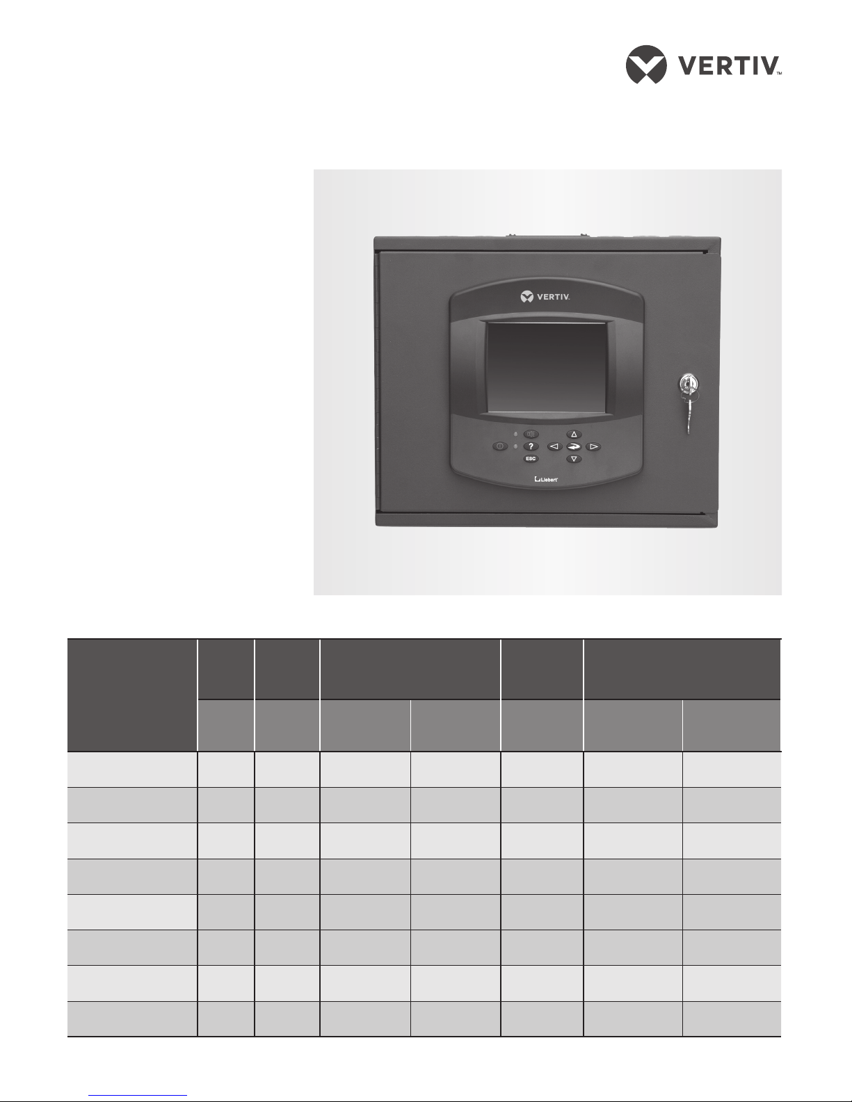
The Liebert vNSA network switch
connects multiple, Ethernet-ready
devices. The vNSA may include
one or two 8-port network
switches, and some models
include a Liebert iCOM™ display to
connect iCOM-equipped Thermal
Management units. See the table
below for details.
NETWORK SWITCHING
The switches in the vNSA include
8 ports: 10/100 Mbps, twisted-pair,
RJ45 and support switched
Ethernet networks in accordance
with IEEE Standard 802.3.
The switches include
autonegotiation, autopolarity, and
autocrossing to eliminate the need
for a crossover cable when
connecting device ports.
The number of Thermal
Management units that you can
connect depends on the vNSA
model. See the table below.
PRODUCT MODELS
Model
iCOM
display
Number
of Ports
Ports required for:
Remaining
available
ports
Maximum number of
connected units for:
- -
iCOM display
connection
Upper and
lower switch
connection
-
small iCOM
display
large iCOM
display
vNSA8-iCOM Yes 8 1 — 7 7 3
vNSA8-iCOM-CR Yes 8 1 — 7 7 3
vNSA8-iCOM-XP Ye s 8 1 — 7 7 3
vNSA16-iCOM Yes 16 1 2 13 13 6
vNSA16-iCOM-CR Yes 16 1 2 13 13 6
vNSA16-iCOM-XP Ye s 16 1 2 13 13 6
vNSA8 No 8 — — 8 8 4
vN SA16 No 16 — 2 14 14 7
LIEBERT® vNSA
TM
Quick Installation Guide
2 59 0-1 61 9- 501A/SL-18 84 0_RE V2_10 -17
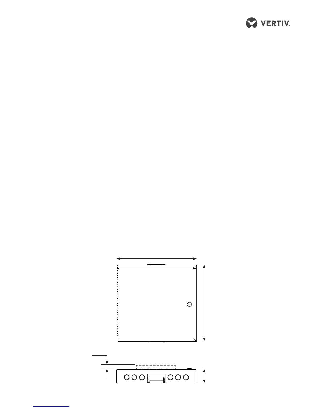
3.3”
(84mm)
DIMENSIONS FRONT, TOP/BOTTOM
PREPARING FOR
IN STALL ATI O N
The Liebert vNSA must be
installed indoors. Choose a
mounting method based on the
application, location of connected
devices, and the type of surface
available for mounting. The
mounting options are:
• Surface-mount: secured to a wall
• Recessed-mount: front flush to
a wall.
Mount the vNSA where it can be
easily accessed.
The site must have electrical
service and must allow networkcable routing from the devices to
the vNSA.
The wall material must be capable
of supporting the weight of the
vNSA. See the Specifications table
on the previous page for weights
by model number.
Required Equipment for
Mounting
Gather the following equipment:
• Electric drill (if pilot holes are
required)
• Screwdriver
• Marker or Pencil to mark hole
locations
• 4 #10 screws
• Wall anchors (if surface cannot
support the unit securely)
Power Requirements
The vNSA requires 100 – 240 VAC,
single-phase power for proper
operation. The unit contains a 12-V,
1.5-A universal power supply with a
hard-wired connection for 120 -V or
230-V operation.
MOUNTING THE vNSA
NOTICE:
Before installing, check
building plans and other relevant
documents to make sure that the
mounting in selected location will
not cut or otherwise damage
electrical wiring, communication
wiring, or pipes.
NOTE
: Remove the conduit
knockouts before mounting to ease
installation and prevent strain on
the hardware and wall.
1. Mark the mounting-hole
locations.
Using the back of the vNSA as
a template, mark the locations
for the 4 screws and drill pilot
holes if necessary.
2. Install the top screws.
The screw heads must be small
enough to fit through the large
hole in the mounting slot, but
extend past the edges of the
upper part of the slot.
3. Hang the unit.
Hang the unit on the installed
top screws and make sure it
slides down until the screws
are in the upper slot, then
tighten the screws until snug.
4. Install the bottom screws.
Insert the screws in the bottom
holes on the back of the panel
and tighten until snug.
14.25”
(361.95mm)
12”
(304.8mm)
0.875”
(22mm)
vNSA16 only
FRONT VIEW
TOP AND BOTTOM VIEW
 Loading...