

Vertiv Liebert THW420 Product Specifications And Installation Manual
TEMPERATURE/HUMIDITY
TRANSMITTER-WALL (4-20 MA)
Product Specification/Installation Guide
590-1616-501A \ SL-31080_REV2_11-17 1
The Liebert THW420 combination
temperature/humidity transmitter is
designed to meet applications that
require local sensing of both
temperature and humidity in a single,
aesthetically pleasing enclosure.
This device incorporates a digital
solid state temperature and
capacitive humidity sensor. The
transmitter requires 24 VDC. The
sensor provides an accurate and
predictable four-wire, 4-20 mA
output signal for temperature and
a second 4-20 mA output signal
for humidity.
Termination
NOTE : Risk of accidental electric
arc. Can cause equipment damage.
Vertiv recommends wiring the
sensor WITHOUT power applied;
accidental arcing may damage the
product and will void the warranty.
The Liebert THW420 transmitter
must be powered from a 24 VDC
supply. The combination
temperature/humidity sensor is
terminated as follows:
• The humidity transmitter
requires a three-wire
termination for the 4-20mA
output using 24 VDC.
• The temperature sensor also
requires a threewire termination.
In most cases, it obtains power
from the analog input to which
it is connected and no external
power is required.
Though interference from external
sources is not a major problem with
current transmitters, Liebert
recommends separating the wiring
from line voltage wiring and from
wiring used to supply highly
inductive loads such as motors,
generators and coils. Vertiv also
recommends making power
connections with twisted pair wire
of at least 22 AWG and crimp-type
connectors.
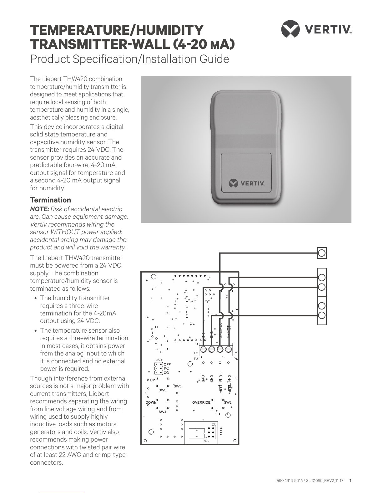
From +24VDC of controller or
power supply
To controller’s analog input
(temperature signal, 4-20mA)
To controller’s analog input
(humidity signal, 4-20mA)
To GND (common) of controller*
4-20mA
Input #1
4-20mA
Input #2
-
+
-
+
* NOTE:
The GND (common) terminal
is common between the
Power and Sensor
+ 24VDC should be used
at all times
TERMINATIONS
TEMPERATURE/HUMIDITY TRANSMITTER - WALL (4-20 MA)
Product Specification/Installation Guide
2 590-1616-501A\SL-31080_REV2 _11-17
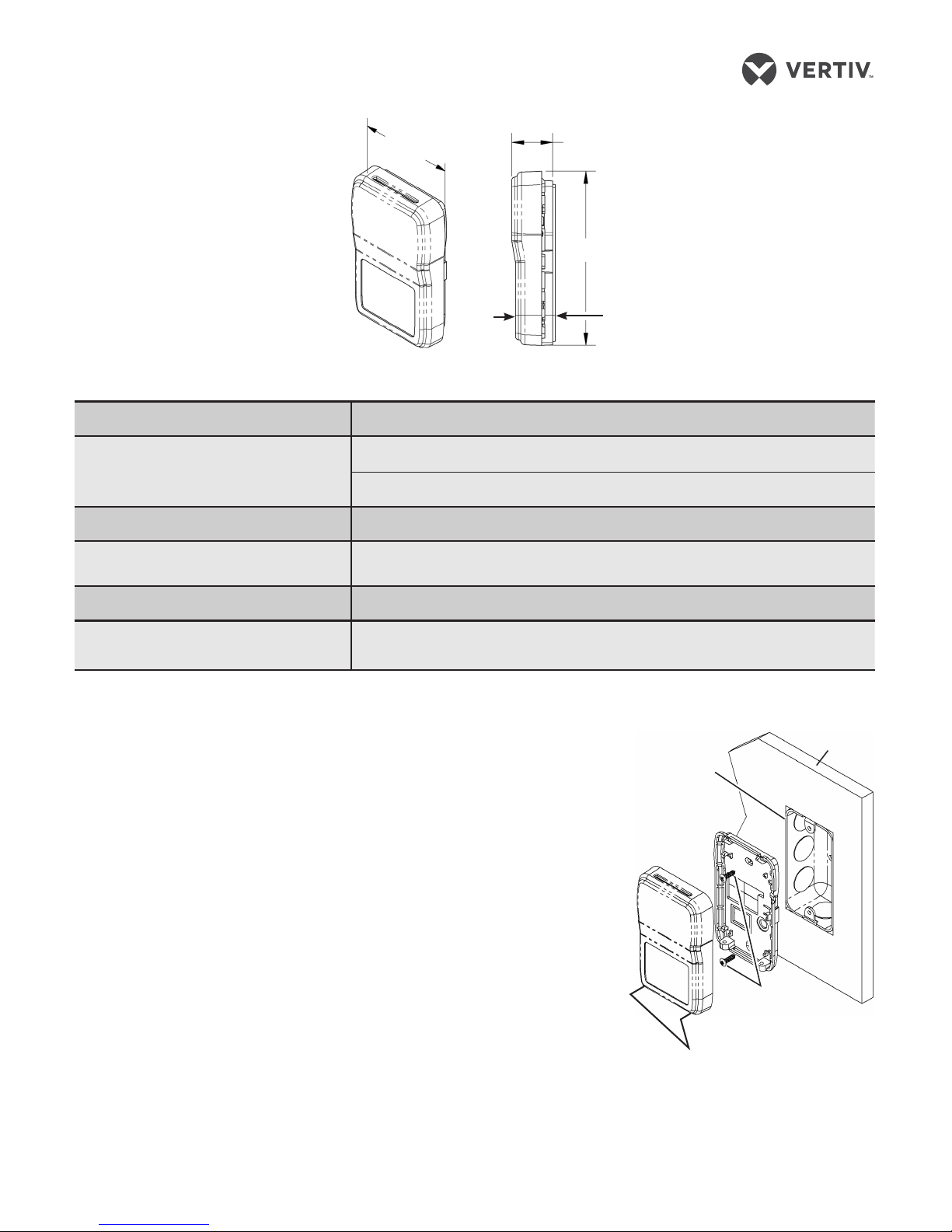
DIMENSIONS
SPECIFICATIONS
Output 4 to 20 mA
Sensor Temperature - Band gap semiconductor
Humidity
Supply Voltage 24 VDC
Tolerance of Resistance (Accuracy) � 1.2° F (�0.6° C)
� 2% RH (from 15 to 95% RH)
Response Time 8 seconds for a 63% step
Environmental Operating Range
(Transmitter)
45° F to 96° F; 0 to 100% RH
(7° C to 35° C); 0 to 100% RH
Front face
2.86” (72.7 mm)
1.06” (26.9 mm)
4.5” (114.3 mm)
Front
Wall
Side
NOTE : In a wall-mount application,
the wall temperature and the
temperature of the air within the
wall cavity can cause erroneous
readings. The mixing of room air
and air from within the wall cavity
can lead to condensation and
premature failure of the sensor.
To prevent these conditions, seal
the conduit leading to the junction
box and seal the hole in the drywall
by using an adhesive backed, foam
insulating pad.
Mounting hardware is provided for
both junction box and drywall
installation.
1. Pull the wires through the
opening in the base plate.
2. For junction box installation:
Secure the base to the box
using the #6-32 x 1/2”
mounting screws provided.
For drywall installation: Drill
two 3/16” holes 3-1/4” apart on
center. Insert the drywall
anchors and secure the base
using the #6 x 1” sheet metal
screws provided.
3. Terminate the unit according to
the guidelines in Termination
on page 1.
4. Attach the cover by latching it
to the top of the base, rotating
the cover down and snapping it
into place.
5. Secure the cover by backing
out the lock-down screws
using a 1/16” Allen wrench until
they are flush with the bottom
of the cover.
MOUNTING
Junction box
2” x 4”
Wall
Mounting
screws
Cover locking screws
1/16” Allen
 Loading...