

Vertiv Liebert STS2 User Manual

Liebert® STS2 /PDU
User Manual—250A-800A, Three-Phase, 60 Hz
™

CONTACTING VERTIV™ FOR SUPPORT
To contact Vertiv Services for information or repair service in the United States, call 800-543-2378. Vertiv
Services offers a complete range of start-up services, repair services, preventive maintenance plans and service
contracts.
For repair or maintenance service outside the 48 contiguous United States, contact Vertiv Services, if available in
your area. For areas not covered by Vertiv Services, the authorized distributor is responsible for providing
qualified, factory-authorized service.
For Vertiv Services to assist you promptly, have the following information available:
Part Numbers:
Serial Numbers:
Rating:
Date Purchased:
Date Installed:
Location:
Input Voltage/Frequency:
Output Voltage/Frequency:
Vertiv™| Liebert® STS2/PDU™ User Manual | Rev. 6 | 10/2017

TABLE OF CONTENTS
CONTACTING VERTIV™ FOR SUPPORT . . . . . . . . . . . . . . . . . . . . . . . . . . . INSIDE FRONT COVER
IMPORTANT SAFETY INSTRUCTIONS . . . . . . . . . . . . . . . . . . . . . . . . . . . . . . . . . . . . . . . . . . . . . . . .1
1.0 UNPACKING AND INSPECTIONS . . . . . . . . . . . . . . . . . . . . . . . . . . . . . . . . . . . . . . . . . . . . . . 3
1.1 External Inspections . . . . . . . . . . . . . . . . . . . . . . . . . . . . . . . . . . . . . . . . . . . . . . . . . . . . . . . . . . . . . . . . . . . . . . . . . . . . . .3
1.2 Unloading and Handling. . . . . . . . . . . . . . . . . . . . . . . . . . . . . . . . . . . . . . . . . . . . . . . . . . . . . . . . . . . . . . . . . . . . . . . . . . .3
1.2.1 Handling Considerations . . . . . . . . . . . . . . . . . . . . . . . . . . . . . . . . . . . . . . . . . . . . . . . . . . . . . . . . . . . . . . . . . . . . . . . . . . 4
1.2.2 Unit Preparation . . . . . . . . . . . . . . . . . . . . . . . . . . . . . . . . . . . . . . . . . . . . . . . . . . . . . . . . . . . . . . . . . . . . . . . . . . . . . . . . . . 4
1.3 Internal Inspection . . . . . . . . . . . . . . . . . . . . . . . . . . . . . . . . . . . . . . . . . . . . . . . . . . . . . . . . . . . . . . . . . . . . . . . . . . . . . . . 4
2.0 LOCATION CONSIDERATIONS. . . . . . . . . . . . . . . . . . . . . . . . . . . . . . . . . . . . . . . . . . . . . . . . . 5
2.1 Recommended Minimum Service Clearances. . . . . . . . . . . . . . . . . . . . . . . . . . . . . . . . . . . . . . . . . . . . . . . . . . . . . . .5
2.2 Heat Output . . . . . . . . . . . . . . . . . . . . . . . . . . . . . . . . . . . . . . . . . . . . . . . . . . . . . . . . . . . . . . . . . . . . . . . . . . . . . . . . . . . . . .5
2.3 Operating Environment . . . . . . . . . . . . . . . . . . . . . . . . . . . . . . . . . . . . . . . . . . . . . . . . . . . . . . . . . . . . . . . . . . . . . . . . . . .5
2.4 Altitude . . . . . . . . . . . . . . . . . . . . . . . . . . . . . . . . . . . . . . . . . . . . . . . . . . . . . . . . . . . . . . . . . . . . . . . . . . . . . . . . . . . . . . . . . 6
3.0 LOCATING THE LIEBERT STS2/PDU . . . . . . . . . . . . . . . . . . . . . . . . . . . . . . . . . . . . . . . . . . . 7
3.1 Anchoring the Unit to the Floor. . . . . . . . . . . . . . . . . . . . . . . . . . . . . . . . . . . . . . . . . . . . . . . . . . . . . . . . . . . . . . . . . . . .7
3.2 Positioning the 250A Only Liebert STS2/PDU Without Anchoring. . . . . . . . . . . . . . . . . . . . . . . . . . . . . . . . . . .7
4.0 POWER AND CONTROL WIRING . . . . . . . . . . . . . . . . . . . . . . . . . . . . . . . . . . . . . . . . . . . . . . . 8
4.1 Input and Output Power Connections. . . . . . . . . . . . . . . . . . . . . . . . . . . . . . . . . . . . . . . . . . . . . . . . . . . . . . . . . . . . . .8
4.2 System Grounding . . . . . . . . . . . . . . . . . . . . . . . . . . . . . . . . . . . . . . . . . . . . . . . . . . . . . . . . . . . . . . . . . . . . . . . . . . . . . . . 11
4.3 Control Wiring Connections . . . . . . . . . . . . . . . . . . . . . . . . . . . . . . . . . . . . . . . . . . . . . . . . . . . . . . . . . . . . . . . . . . . . . . 11
4.4 Remote Source Selection Wiring. . . . . . . . . . . . . . . . . . . . . . . . . . . . . . . . . . . . . . . . . . . . . . . . . . . . . . . . . . . . . . . . . . 12
4.5 Power Supply . . . . . . . . . . . . . . . . . . . . . . . . . . . . . . . . . . . . . . . . . . . . . . . . . . . . . . . . . . . . . . . . . . . . . . . . . . . . . . . . . . . .12
5.0 OUTPUT POWER WIRING . . . . . . . . . . . . . . . . . . . . . . . . . . . . . . . . . . . . . . . . . . . . . . . . . . . . .13
5.1 Customer Connections . . . . . . . . . . . . . . . . . . . . . . . . . . . . . . . . . . . . . . . . . . . . . . . . . . . . . . . . . . . . . . . . . . . . . . . . . . .13
6.0 OPTIONS . . . . . . . . . . . . . . . . . . . . . . . . . . . . . . . . . . . . . . . . . . . . . . . . . . . . . . . . . . . . . . . . . . . 14
6.1 Programmable Relay Board. . . . . . . . . . . . . . . . . . . . . . . . . . . . . . . . . . . . . . . . . . . . . . . . . . . . . . . . . . . . . . . . . . . . . . .14
6.2 Input Contact Isolator Board . . . . . . . . . . . . . . . . . . . . . . . . . . . . . . . . . . . . . . . . . . . . . . . . . . . . . . . . . . . . . . . . . . . . .15
6.3 Comms Board. . . . . . . . . . . . . . . . . . . . . . . . . . . . . . . . . . . . . . . . . . . . . . . . . . . . . . . . . . . . . . . . . . . . . . . . . . . . . . . . . . . . 15
6.4 Liebert IntelliSlot™ Web/485 Card With Adapter. . . . . . . . . . . . . . . . . . . . . . . . . . . . . . . . . . . . . . . . . . . . . . . . . . .15
6.5 Remote Source Selection. . . . . . . . . . . . . . . . . . . . . . . . . . . . . . . . . . . . . . . . . . . . . . . . . . . . . . . . . . . . . . . . . . . . . . . . .16
6.6 Key Lockout Switch . . . . . . . . . . . . . . . . . . . . . . . . . . . . . . . . . . . . . . . . . . . . . . . . . . . . . . . . . . . . . . . . . . . . . . . . . . . . . .16
6.7 Static Switch Redundant Output Breaker . . . . . . . . . . . . . . . . . . . . . . . . . . . . . . . . . . . . . . . . . . . . . . . . . . . . . . . . .16
6.8 Inline Panelboards . . . . . . . . . . . . . . . . . . . . . . . . . . . . . . . . . . . . . . . . . . . . . . . . . . . . . . . . . . . . . . . . . . . . . . . . . . . . . . .16
6.9 I-Line Panelboards . . . . . . . . . . . . . . . . . . . . . . . . . . . . . . . . . . . . . . . . . . . . . . . . . . . . . . . . . . . . . . . . . . . . . . . . . . . . . . .16
6.10 Subfeed Breakers . . . . . . . . . . . . . . . . . . . . . . . . . . . . . . . . . . . . . . . . . . . . . . . . . . . . . . . . . . . . . . . . . . . . . . . . . . . . . . . .16
6.11 K-Factor Transformers . . . . . . . . . . . . . . . . . . . . . . . . . . . . . . . . . . . . . . . . . . . . . . . . . . . . . . . . . . . . . . . . . . . . . . . . . . .16
6.12 Surge Suppression System . . . . . . . . . . . . . . . . . . . . . . . . . . . . . . . . . . . . . . . . . . . . . . . . . . . . . . . . . . . . . . . . . . . . . . .16
Vertiv | Liebert STS2/PDU User Manual | Rev. 6 | 10/17 i

7.0 INSTALLATION DRAWINGS . . . . . . . . . . . . . . . . . . . . . . . . . . . . . . . . . . . . . . . . . . . . . . . . . . .17
8.0 INTRODUCTION TO LIEBERT STS2/PDU OPERATION . . . . . . . . . . . . . . . . . . . . . . . . . . 68
8.1 System Description . . . . . . . . . . . . . . . . . . . . . . . . . . . . . . . . . . . . . . . . . . . . . . . . . . . . . . . . . . . . . . . . . . . . . . . . . . . . . 68
8.1.1 Redundancy . . . . . . . . . . . . . . . . . . . . . . . . . . . . . . . . . . . . . . . . . . . . . . . . . . . . . . . . . . . . . . . . . . . . . . . . . . . . . . . . . . . . . 68
8.1.2 Reliability and Agency Requirements . . . . . . . . . . . . . . . . . . . . . . . . . . . . . . . . . . . . . . . . . . . . . . . . . . . . . . . . . . . . . 69
8.1.3 Factory Backup and Service Assistance . . . . . . . . . . . . . . . . . . . . . . . . . . . . . . . . . . . . . . . . . . . . . . . . . . . . . . . . . . 69
8.2 Modes of Operation . . . . . . . . . . . . . . . . . . . . . . . . . . . . . . . . . . . . . . . . . . . . . . . . . . . . . . . . . . . . . . . . . . . . . . . . . . . . . 69
8.2.1 Normal (Preferred Source) . . . . . . . . . . . . . . . . . . . . . . . . . . . . . . . . . . . . . . . . . . . . . . . . . . . . . . . . . . . . . . . . . . . . . . . 69
8.2.2 Transfer . . . . . . . . . . . . . . . . . . . . . . . . . . . . . . . . . . . . . . . . . . . . . . . . . . . . . . . . . . . . . . . . . . . . . . . . . . . . . . . . . . . . . . . . . 70
8.2.3 Transfer Inhibit . . . . . . . . . . . . . . . . . . . . . . . . . . . . . . . . . . . . . . . . . . . . . . . . . . . . . . . . . . . . . . . . . . . . . . . . . . . . . . . . . . 70
8.2.4 Bypass . . . . . . . . . . . . . . . . . . . . . . . . . . . . . . . . . . . . . . . . . . . . . . . . . . . . . . . . . . . . . . . . . . . . . . . . . . . . . . . . . . . . . . . . . . 70
8.3 Operator Controls. . . . . . . . . . . . . . . . . . . . . . . . . . . . . . . . . . . . . . . . . . . . . . . . . . . . . . . . . . . . . . . . . . . . . . . . . . . . . . . 70
9.0 THEORY OF OPERATION. . . . . . . . . . . . . . . . . . . . . . . . . . . . . . . . . . . . . . . . . . . . . . . . . . . . . .71
9.1 General Description . . . . . . . . . . . . . . . . . . . . . . . . . . . . . . . . . . . . . . . . . . . . . . . . . . . . . . . . . . . . . . . . . . . . . . . . . . . . . . 71
9.1.1 Liebert Static Transfer Switch 2/Power Distribution Unit . . . . . . . . . . . . . . . . . . . . . . . . . . . . . . . . . . . . . . . . . . .71
9.1.2 Source Transfer. . . . . . . . . . . . . . . . . . . . . . . . . . . . . . . . . . . . . . . . . . . . . . . . . . . . . . . . . . . . . . . . . . . . . . . . . . . . . . . . . . .71
9.1.3 Automatic Transfer/Retransfer . . . . . . . . . . . . . . . . . . . . . . . . . . . . . . . . . . . . . . . . . . . . . . . . . . . . . . . . . . . . . . . . . . . .71
9.1.4 Emergency Transfer . . . . . . . . . . . . . . . . . . . . . . . . . . . . . . . . . . . . . . . . . . . . . . . . . . . . . . . . . . . . . . . . . . . . . . . . . . . . . 72
9.1.5 Load Current Transfer Inhibit. . . . . . . . . . . . . . . . . . . . . . . . . . . . . . . . . . . . . . . . . . . . . . . . . . . . . . . . . . . . . . . . . . . . . 72
9.1.6 SCR Failure . . . . . . . . . . . . . . . . . . . . . . . . . . . . . . . . . . . . . . . . . . . . . . . . . . . . . . . . . . . . . . . . . . . . . . . . . . . . . . . . . . . . . . 72
9.1.7 On/Off Sequence . . . . . . . . . . . . . . . . . . . . . . . . . . . . . . . . . . . . . . . . . . . . . . . . . . . . . . . . . . . . . . . . . . . . . . . . . . . . . . . . 72
9.2 Detailed Component Description . . . . . . . . . . . . . . . . . . . . . . . . . . . . . . . . . . . . . . . . . . . . . . . . . . . . . . . . . . . . . . . . 72
9.2.1 Controls. . . . . . . . . . . . . . . . . . . . . . . . . . . . . . . . . . . . . . . . . . . . . . . . . . . . . . . . . . . . . . . . . . . . . . . . . . . . . . . . . . . . . . . . . 72
9.2.2 Circuit Breakers and Non-Automatic Circuit Breakers . . . . . . . . . . . . . . . . . . . . . . . . . . . . . . . . . . . . . . . . . . . . . 73
9.2.3 SCRs . . . . . . . . . . . . . . . . . . . . . . . . . . . . . . . . . . . . . . . . . . . . . . . . . . . . . . . . . . . . . . . . . . . . . . . . . . . . . . . . . . . . . . . . . . . . 73
9.2.4 Logic Modules . . . . . . . . . . . . . . . . . . . . . . . . . . . . . . . . . . . . . . . . . . . . . . . . . . . . . . . . . . . . . . . . . . . . . . . . . . . . . . . . . . . 73
9.2.5 Audible Alarm . . . . . . . . . . . . . . . . . . . . . . . . . . . . . . . . . . . . . . . . . . . . . . . . . . . . . . . . . . . . . . . . . . . . . . . . . . . . . . . . . . . 74
9.2.6 RS-232 Port . . . . . . . . . . . . . . . . . . . . . . . . . . . . . . . . . . . . . . . . . . . . . . . . . . . . . . . . . . . . . . . . . . . . . . . . . . . . . . . . . . . . . 74
10.0 OPERATING INSTRUCTIONS . . . . . . . . . . . . . . . . . . . . . . . . . . . . . . . . . . . . . . . . . . . . . . . . . 75
10.1 Normal System Turn-On. . . . . . . . . . . . . . . . . . . . . . . . . . . . . . . . . . . . . . . . . . . . . . . . . . . . . . . . . . . . . . . . . . . . . . . . . 76
10.2 Manual Transfer / Preferred Source Selection . . . . . . . . . . . . . . . . . . . . . . . . . . . . . . . . . . . . . . . . . . . . . . . . . . . . 77
10.3 Enabling Remote Source Selection. . . . . . . . . . . . . . . . . . . . . . . . . . . . . . . . . . . . . . . . . . . . . . . . . . . . . . . . . . . . . . . 78
10.4 Maintenance Bypass . . . . . . . . . . . . . . . . . . . . . . . . . . . . . . . . . . . . . . . . . . . . . . . . . . . . . . . . . . . . . . . . . . . . . . . . . . . . 78
10.4.1 Bypass Procedures for Source 1 . . . . . . . . . . . . . . . . . . . . . . . . . . . . . . . . . . . . . . . . . . . . . . . . . . . . . . . . . . . . . . . . . . 79
10.4.2 Bypass Procedures for Source 2 . . . . . . . . . . . . . . . . . . . . . . . . . . . . . . . . . . . . . . . . . . . . . . . . . . . . . . . . . . . . . . . . . . 80
10.5 Normal System Shutdown . . . . . . . . . . . . . . . . . . . . . . . . . . . . . . . . . . . . . . . . . . . . . . . . . . . . . . . . . . . . . . . . . . . . . . . .81
10.5.1 Shutdown in Static Transfer Switch Mode. . . . . . . . . . . . . . . . . . . . . . . . . . . . . . . . . . . . . . . . . . . . . . . . . . . . . . . . . .81
10.5.2 Shutdown in Maintenance Bypass Mode . . . . . . . . . . . . . . . . . . . . . . . . . . . . . . . . . . . . . . . . . . . . . . . . . . . . . . . . . . .81
11.0 ALARMS AND FAULTS. . . . . . . . . . . . . . . . . . . . . . . . . . . . . . . . . . . . . . . . . . . . . . . . . . . . . . . 82
11.1 Event Mask . . . . . . . . . . . . . . . . . . . . . . . . . . . . . . . . . . . . . . . . . . . . . . . . . . . . . . . . . . . . . . . . . . . . . . . . . . . . . . . . . . . . . 82
11.2 Event and History Logs . . . . . . . . . . . . . . . . . . . . . . . . . . . . . . . . . . . . . . . . . . . . . . . . . . . . . . . . . . . . . . . . . . . . . . . . . 83
11.2.1 Event Log . . . . . . . . . . . . . . . . . . . . . . . . . . . . . . . . . . . . . . . . . . . . . . . . . . . . . . . . . . . . . . . . . . . . . . . . . . . . . . . . . . . . . . . 83
11.2.2 History Log. . . . . . . . . . . . . . . . . . . . . . . . . . . . . . . . . . . . . . . . . . . . . . . . . . . . . . . . . . . . . . . . . . . . . . . . . . . . . . . . . . . . . . 83
11.3 Alarm Notes . . . . . . . . . . . . . . . . . . . . . . . . . . . . . . . . . . . . . . . . . . . . . . . . . . . . . . . . . . . . . . . . . . . . . . . . . . . . . . . . . . . . 84
11.4 List of Messages . . . . . . . . . . . . . . . . . . . . . . . . . . . . . . . . . . . . . . . . . . . . . . . . . . . . . . . . . . . . . . . . . . . . . . . . . . . . . . . . 84
Vertiv | Liebert STS2/PDU User Manual | Rev. 6 | 10/17 ii

12.0 COMMUNICATION INTERFACES. . . . . . . . . . . . . . . . . . . . . . . . . . . . . . . . . . . . . . . . . . . . . . 87
12.1 Using the RS-232 Port. . . . . . . . . . . . . . . . . . . . . . . . . . . . . . . . . . . . . . . . . . . . . . . . . . . . . . . . . . . . . . . . . . . . . . . . . . . 88
12.1.1 Connecting and Using a Terminal. . . . . . . . . . . . . . . . . . . . . . . . . . . . . . . . . . . . . . . . . . . . . . . . . . . . . . . . . . . . . . . . . 88
12.1.2 Configuring the Liebert STS2/PDU via the Terminal. . . . . . . . . . . . . . . . . . . . . . . . . . . . . . . . . . . . . . . . . . . . . . . 89
12.1.3 Setting Bitpacked Options With the Terminal . . . . . . . . . . . . . . . . . . . . . . . . . . . . . . . . . . . . . . . . . . . . . . . . . . . . . 92
12.1.4 Setting Event Masks with the Terminal . . . . . . . . . . . . . . . . . . . . . . . . . . . . . . . . . . . . . . . . . . . . . . . . . . . . . . . . . . . 94
13.0 TOUCHSCREEN DISPLAY . . . . . . . . . . . . . . . . . . . . . . . . . . . . . . . . . . . . . . . . . . . . . . . . . . . . 96
13.1 Display Overview . . . . . . . . . . . . . . . . . . . . . . . . . . . . . . . . . . . . . . . . . . . . . . . . . . . . . . . . . . . . . . . . . . . . . . . . . . . . . . . 96
13.2 Menu Overview . . . . . . . . . . . . . . . . . . . . . . . . . . . . . . . . . . . . . . . . . . . . . . . . . . . . . . . . . . . . . . . . . . . . . . . . . . . . . . . . . 97
13.2.1 Security . . . . . . . . . . . . . . . . . . . . . . . . . . . . . . . . . . . . . . . . . . . . . . . . . . . . . . . . . . . . . . . . . . . . . . . . . . . . . . . . . . . . . . . . . 98
13.3 Mimic Display. . . . . . . . . . . . . . . . . . . . . . . . . . . . . . . . . . . . . . . . . . . . . . . . . . . . . . . . . . . . . . . . . . . . . . . . . . . . . . . . . . . 99
13.4 Event Controls. . . . . . . . . . . . . . . . . . . . . . . . . . . . . . . . . . . . . . . . . . . . . . . . . . . . . . . . . . . . . . . . . . . . . . . . . . . . . . . . . . 99
13.5 Event Display . . . . . . . . . . . . . . . . . . . . . . . . . . . . . . . . . . . . . . . . . . . . . . . . . . . . . . . . . . . . . . . . . . . . . . . . . . . . . . . . . . . 99
13.6 Menu Bar . . . . . . . . . . . . . . . . . . . . . . . . . . . . . . . . . . . . . . . . . . . . . . . . . . . . . . . . . . . . . . . . . . . . . . . . . . . . . . . . . . . . . . . 99
13.7 Configuration Menu . . . . . . . . . . . . . . . . . . . . . . . . . . . . . . . . . . . . . . . . . . . . . . . . . . . . . . . . . . . . . . . . . . . . . . . . . . . . . 99
13.7.1 Logs . . . . . . . . . . . . . . . . . . . . . . . . . . . . . . . . . . . . . . . . . . . . . . . . . . . . . . . . . . . . . . . . . . . . . . . . . . . . . . . . . . . . . . . . . . . . 113
13.7.2 Source Transfers. . . . . . . . . . . . . . . . . . . . . . . . . . . . . . . . . . . . . . . . . . . . . . . . . . . . . . . . . . . . . . . . . . . . . . . . . . . . . . . . . 114
13.7.3 Startup Procedure . . . . . . . . . . . . . . . . . . . . . . . . . . . . . . . . . . . . . . . . . . . . . . . . . . . . . . . . . . . . . . . . . . . . . . . . . . . . . . . 114
13.7.4 Bypass Procedure . . . . . . . . . . . . . . . . . . . . . . . . . . . . . . . . . . . . . . . . . . . . . . . . . . . . . . . . . . . . . . . . . . . . . . . . . . . . . . . 114
13.7.5 Help. . . . . . . . . . . . . . . . . . . . . . . . . . . . . . . . . . . . . . . . . . . . . . . . . . . . . . . . . . . . . . . . . . . . . . . . . . . . . . . . . . . . . . . . . . . . .114
13.7.6 Logo . . . . . . . . . . . . . . . . . . . . . . . . . . . . . . . . . . . . . . . . . . . . . . . . . . . . . . . . . . . . . . . . . . . . . . . . . . . . . . . . . . . . . . . . . . . .114
13.8 Cleaning the LCD Touchscreen . . . . . . . . . . . . . . . . . . . . . . . . . . . . . . . . . . . . . . . . . . . . . . . . . . . . . . . . . . . . . . . . . . 114
14.0 SPECIFICATIONS . . . . . . . . . . . . . . . . . . . . . . . . . . . . . . . . . . . . . . . . . . . . . . . . . . . . . . . . . . . .115
14.1 System Configuration . . . . . . . . . . . . . . . . . . . . . . . . . . . . . . . . . . . . . . . . . . . . . . . . . . . . . . . . . . . . . . . . . . . . . . . . . . . 115
14.1.1 Frequency . . . . . . . . . . . . . . . . . . . . . . . . . . . . . . . . . . . . . . . . . . . . . . . . . . . . . . . . . . . . . . . . . . . . . . . . . . . . . . . . . . . . . . . 115
14.1.2 Input Voltage . . . . . . . . . . . . . . . . . . . . . . . . . . . . . . . . . . . . . . . . . . . . . . . . . . . . . . . . . . . . . . . . . . . . . . . . . . . . . . . . . . . .115
14.1.3 Output Voltage . . . . . . . . . . . . . . . . . . . . . . . . . . . . . . . . . . . . . . . . . . . . . . . . . . . . . . . . . . . . . . . . . . . . . . . . . . . . . . . . . . 115
14.1.4 System Current Ratings . . . . . . . . . . . . . . . . . . . . . . . . . . . . . . . . . . . . . . . . . . . . . . . . . . . . . . . . . . . . . . . . . . . . . . . . . . 115
14.1.5 Grounding . . . . . . . . . . . . . . . . . . . . . . . . . . . . . . . . . . . . . . . . . . . . . . . . . . . . . . . . . . . . . . . . . . . . . . . . . . . . . . . . . . . . . . .116
14.1.6 Electrical Requirements . . . . . . . . . . . . . . . . . . . . . . . . . . . . . . . . . . . . . . . . . . . . . . . . . . . . . . . . . . . . . . . . . . . . . . . . . .116
14.1.7 Surge Suppression. . . . . . . . . . . . . . . . . . . . . . . . . . . . . . . . . . . . . . . . . . . . . . . . . . . . . . . . . . . . . . . . . . . . . . . . . . . . . . . 116
14.1.8 Response Time . . . . . . . . . . . . . . . . . . . . . . . . . . . . . . . . . . . . . . . . . . . . . . . . . . . . . . . . . . . . . . . . . . . . . . . . . . . . . . . . . .116
14.1.9 Environmental Requirements. . . . . . . . . . . . . . . . . . . . . . . . . . . . . . . . . . . . . . . . . . . . . . . . . . . . . . . . . . . . . . . . . . . . . 116
Vertiv | Liebert STS2/PDU User Manual | Rev. 6 | 10/17 iii

14.2 System Components . . . . . . . . . . . . . . . . . . . . . . . . . . . . . . . . . . . . . . . . . . . . . . . . . . . . . . . . . . . . . . . . . . . . . . . . . . . . 117
14.2.1 Frame and Enclosure. . . . . . . . . . . . . . . . . . . . . . . . . . . . . . . . . . . . . . . . . . . . . . . . . . . . . . . . . . . . . . . . . . . . . . . . . . . . . 117
14.2.2 Casters - 250A only. . . . . . . . . . . . . . . . . . . . . . . . . . . . . . . . . . . . . . . . . . . . . . . . . . . . . . . . . . . . . . . . . . . . . . . . . . . . . . 117
14.2.3 Cooling. . . . . . . . . . . . . . . . . . . . . . . . . . . . . . . . . . . . . . . . . . . . . . . . . . . . . . . . . . . . . . . . . . . . . . . . . . . . . . . . . . . . . . . . . . 117
14.2.4 Access . . . . . . . . . . . . . . . . . . . . . . . . . . . . . . . . . . . . . . . . . . . . . . . . . . . . . . . . . . . . . . . . . . . . . . . . . . . . . . . . . . . . . . . . . .118
14.2.5 Circuit Breakers . . . . . . . . . . . . . . . . . . . . . . . . . . . . . . . . . . . . . . . . . . . . . . . . . . . . . . . . . . . . . . . . . . . . . . . . . . . . . . . . . 118
14.2.6 Cable Entrance . . . . . . . . . . . . . . . . . . . . . . . . . . . . . . . . . . . . . . . . . . . . . . . . . . . . . . . . . . . . . . . . . . . . . . . . . . . . . . . . . .118
14.2.7 Doors . . . . . . . . . . . . . . . . . . . . . . . . . . . . . . . . . . . . . . . . . . . . . . . . . . . . . . . . . . . . . . . . . . . . . . . . . . . . . . . . . . . . . . . . . . . 118
14.2.8 Color Graphical Display . . . . . . . . . . . . . . . . . . . . . . . . . . . . . . . . . . . . . . . . . . . . . . . . . . . . . . . . . . . . . . . . . . . . . . . . . . 119
14.2.9 RS-232 Port . . . . . . . . . . . . . . . . . . . . . . . . . . . . . . . . . . . . . . . . . . . . . . . . . . . . . . . . . . . . . . . . . . . . . . . . . . . . . . . . . . . . .119
14.2.10 Terminal Port Connections . . . . . . . . . . . . . . . . . . . . . . . . . . . . . . . . . . . . . . . . . . . . . . . . . . . . . . . . . . . . . . . . . . . . . . . 119
14.2.11 RS-232 Interface Parameters . . . . . . . . . . . . . . . . . . . . . . . . . . . . . . . . . . . . . . . . . . . . . . . . . . . . . . . . . . . . . . . . . . . . 120
14.2.12 Maintenance Bypass . . . . . . . . . . . . . . . . . . . . . . . . . . . . . . . . . . . . . . . . . . . . . . . . . . . . . . . . . . . . . . . . . . . . . . . . . . . . 120
14.2.13 Fuseless Design . . . . . . . . . . . . . . . . . . . . . . . . . . . . . . . . . . . . . . . . . . . . . . . . . . . . . . . . . . . . . . . . . . . . . . . . . . . . . . . . 120
14.2.14 Options . . . . . . . . . . . . . . . . . . . . . . . . . . . . . . . . . . . . . . . . . . . . . . . . . . . . . . . . . . . . . . . . . . . . . . . . . . . . . . . . . . . . . . . . 120
15.0 EVENT MESSAGE HELP TEXT. . . . . . . . . . . . . . . . . . . . . . . . . . . . . . . . . . . . . . . . . . . . . . . . 121
16.0 MAINTENANCE . . . . . . . . . . . . . . . . . . . . . . . . . . . . . . . . . . . . . . . . . . . . . . . . . . . . . . . . . . . . 145
16.1 Proper Tightening of Nuts and Bolts . . . . . . . . . . . . . . . . . . . . . . . . . . . . . . . . . . . . . . . . . . . . . . . . . . . . . . . . . . . . 145
16.2 Testing the Liebert STS2/PDU. . . . . . . . . . . . . . . . . . . . . . . . . . . . . . . . . . . . . . . . . . . . . . . . . . . . . . . . . . . . . . . . . . 145
16.3 Changing the Air Filter . . . . . . . . . . . . . . . . . . . . . . . . . . . . . . . . . . . . . . . . . . . . . . . . . . . . . . . . . . . . . . . . . . . . . . . . . 145
17.0 CUSTOMER SETTINGS. . . . . . . . . . . . . . . . . . . . . . . . . . . . . . . . . . . . . . . . . . . . . . . . . . . . . . 146
17.1 Programmable Relay Board Settings . . . . . . . . . . . . . . . . . . . . . . . . . . . . . . . . . . . . . . . . . . . . . . . . . . . . . . . . . . . . 146
17.2 Input Contact Isolator Settings . . . . . . . . . . . . . . . . . . . . . . . . . . . . . . . . . . . . . . . . . . . . . . . . . . . . . . . . . . . . . . . . . 148
FIGURES
Figure 1 Recommended derating for high altitude operation . . . . . . . . . . . . . . . . . . . . . . . . . . . . . . . . . . . . . . . . . . . . 6
Figure 2 Maximum ambient temperature for full load operation at higher altitudes . . . . . . . . . . . . . . . . . . . . . . 6
Figure 3 Typical Liebert STS2/PDU, one-line diagram . . . . . . . . . . . . . . . . . . . . . . . . . . . . . . . . . . . . . . . . . . . . . . . . . . 9
Figure 4 Typical Liebert STS2/PDU, one-line diagram, with dual static switch output circuit breakers
(not available on 250A units) . . . . . . . . . . . . . . . . . . . . . . . . . . . . . . . . . . . . . . . . . . . . . . . . . . . . . . . . . . . . . . . . . 9
Figure 5 Typical Liebert STS2/PDU, one-line diagram, with inline distribution, dual static switch output
circuit breakers . . . . . . . . . . . . . . . . . . . . . . . . . . . . . . . . . . . . . . . . . . . . . . . . . . . . . . . . . . . . . . . . . . . . . . . . . . . . . .10
Figure 6 Typical Liebert STS2/PDU, one-line diagram, with I-Line distribution, dual static switch output
circuit breakers . . . . . . . . . . . . . . . . . . . . . . . . . . . . . . . . . . . . . . . . . . . . . . . . . . . . . . . . . . . . . . . . . . . . . . . . . . . . . .10
Figure 7 Outline drawing, 250A Liebert STS2/PDU . . . . . . . . . . . . . . . . . . . . . . . . . . . . . . . . . . . . . . . . . . . . . . . . . . . . .17
Figure 8 Outline drawing, 250A Liebert STS2/PDU with right side I-Line distribution . . . . . . . . . . . . . . . . . . . .18
Figure 9 Outline drawing, 250A Liebert STS2/PDU with right side inline distribution. . . . . . . . . . . . . . . . . . . . .19
Figure 10 Outline drawing, 250A Liebert STS2/PDU with left side I-Line distribution. . . . . . . . . . . . . . . . . . . . . 20
Figure 11 Outline drawing, 250A Liebert STS2/PDU with left side Inline distribution . . . . . . . . . . . . . . . . . . . . . .21
Figure 12 Outline drawing,400-600A Liebert STS2/PDU with right side inline distribution . . . . . . . . . . . . . . . 22
Figure 13 Outline drawing, 400-600A Liebert STS2/PDU with right side output breaker or I-Line
distribution . . . . . . . . . . . . . . . . . . . . . . . . . . . . . . . . . . . . . . . . . . . . . . . . . . . . . . . . . . . . . . . . . . . . . . . . . . . . . . . . . 23
Figure 14 Outline drawing, 400-600A Liebert STS2/PDU with left side inline distribution . . . . . . . . . . . . . . . . 24
Figure 15 Outline drawing, 400-600A Liebert STS2/PDU with left side output breaker or I-Line
distribution . . . . . . . . . . . . . . . . . . . . . . . . . . . . . . . . . . . . . . . . . . . . . . . . . . . . . . . . . . . . . . . . . . . . . . . . . . . . . . . . . 25
Vertiv | Liebert STS2/PDU User Manual | Rev. 6 | 10/17 iv

Figure 16 Outline drawing, 800A Liebert STS2/PDU with right side output breaker or I-Line
distribution . . . . . . . . . . . . . . . . . . . . . . . . . . . . . . . . . . . . . . . . . . . . . . . . . . . . . . . . . . . . . . . . . . . . . . . . . . . . . . . . . 26
Figure 17 Outline drawing, 800A Liebert STS2/PDU with right side inline distribution . . . . . . . . . . . . . . . . . . . 27
Figure 18 Outline drawing, 800A Liebert STS2/PDU with left side output breaker or I-Line
distribution . . . . . . . . . . . . . . . . . . . . . . . . . . . . . . . . . . . . . . . . . . . . . . . . . . . . . . . . . . . . . . . . . . . . . . . . . . . . . . . . . 28
Figure 19 Outline drawing, 800A Liebert STS2/PDU with left side inline distribution. . . . . . . . . . . . . . . . . . . . . 29
Figure 20 Outline drawing, 250A Liebert STS2/PDU with key lockout switch option. . . . . . . . . . . . . . . . . . . . . . 30
Figure 21 Outline drawing, 400-600A Liebert STS2/PDU, inline distribution, right side with key
lockout switch option . . . . . . . . . . . . . . . . . . . . . . . . . . . . . . . . . . . . . . . . . . . . . . . . . . . . . . . . . . . . . . . . . . . . . . . .31
Figure 22 Outline drawing, 800A Liebert STS2/PDU, inline distribution, right side with key lockout
switch option . . . . . . . . . . . . . . . . . . . . . . . . . . . . . . . . . . . . . . . . . . . . . . . . . . . . . . . . . . . . . . . . . . . . . . . . . . . . . . . 32
Figure 23 Electrical field connections, 250A Liebert STS2/PDU input/output with CB8. . . . . . . . . . . . . . . . . . . 33
Figure 24 Electrical field connections, 250A Liebert STS2/PDU input with CB3 . . . . . . . . . . . . . . . . . . . . . . . . . . 34
Figure 25 Electrical field connections, 250A Liebert STS2/PDU input with CB3 & CB3A . . . . . . . . . . . . . . . . . 35
Figure 26 Electrical field connections, 400-600A Liebert STS2/PDU input with CB3. . . . . . . . . . . . . . . . . . . . . 36
Figure 27 Electrical field connections, 400-600A Liebert STS2/PDU input with CB3 and CB3A . . . . . . . . . . 37
Figure 28 Electrical field connections, 800A Liebert STS2/PDU input with CB3. . . . . . . . . . . . . . . . . . . . . . . . . . 38
Figure 29 Electrical field connections, 800A Liebert STS2/PDU input with CB3 and CB3A . . . . . . . . . . . . . . . 39
Figure 30 Electrical field connections, 250A Liebert STS2/PDU output with inline panelboards. . . . . . . . . . . 40
Figure 31 Electrical field connections, 400-800A Liebert STS2/PDU output with inline panelboards . . . . . .41
Figure 32 Electrical field connections, Liebert STS2/PDU output with I-Line panelboard . . . . . . . . . . . . . . . . . 42
Figure 33 Electrical field connections, 400-600A Liebert STS2/PDU with right side output breaker . . . . . . 43
Figure 34 Electrical field connections, 400-600A Liebert STS2/PDU with left side output breaker . . . . . . . 44
Figure 35 Electrical field connections, 800A Liebert STS2/PDU with right side output breaker . . . . . . . . . . . 45
Figure 36 Electrical field connections, 8600A Liebert STS2/PDU with left side output breaker . . . . . . . . . . . 46
Figure 37 Electrical field connections, 800A Liebert STS2/PDU interconnect wiring . . . . . . . . . . . . . . . . . . . . . 47
Figure 38 Electrical field connections, 800A Liebert STS2/PDU interconnect wiring, breaker section . . . . . 48
Figure 39 Electrical field connections, 800A Liebert STS2/PDU interconnect wiring, STS section . . . . . . . . 49
Figure 40 Electrical field connections, 800A Liebert STS2/PDU interconnect wiring, left side
distribution cabinet . . . . . . . . . . . . . . . . . . . . . . . . . . . . . . . . . . . . . . . . . . . . . . . . . . . . . . . . . . . . . . . . . . . . . . . . . 50
Figure 41 Electrical field connections, 800A Liebert STS2/PDU interconnect wiring, left side one-line . . . . . 51
Figure 42 Electrical field connections, 800A Liebert STS2/PDU interconnect wiring, left side one-line
with CB3A . . . . . . . . . . . . . . . . . . . . . . . . . . . . . . . . . . . . . . . . . . . . . . . . . . . . . . . . . . . . . . . . . . . . . . . . . . . . . . . . . . 52
Figure 43 Electrical field connections, 800A Liebert STS2/PDU interconnect wiring, right side
one-line. . . . . . . . . . . . . . . . . . . . . . . . . . . . . . . . . . . . . . . . . . . . . . . . . . . . . . . . . . . . . . . . . . . . . . . . . . . . . . . . . . . . . 53
Figure 44 Electrical field connections, 800A Liebert STS2/PDU interconnect wiring, right side
one-line with CB3A. . . . . . . . . . . . . . . . . . . . . . . . . . . . . . . . . . . . . . . . . . . . . . . . . . . . . . . . . . . . . . . . . . . . . . . . . . 54
Figure 45 Control wiring, 800A Liebert STS2/PDU, left side distribution. . . . . . . . . . . . . . . . . . . . . . . . . . . . . . . . . 55
Figure 46 Control wiring, 800A Liebert STS2/PDU, right side distribution . . . . . . . . . . . . . . . . . . . . . . . . . . . . . . . 56
Figure 47 Control connection location, 250A Liebert STS2/PDU . . . . . . . . . . . . . . . . . . . . . . . . . . . . . . . . . . . . . . . . 57
Figure 48 Control connection location, 400-800A Liebert STS2/PDU . . . . . . . . . . . . . . . . . . . . . . . . . . . . . . . . . . . 58
Figure 49 Control location drawing conduit box, top entry, 400-600A Liebert STS2/PDU . . . . . . . . . . . . . . . . 59
Figure 50 Control wiring for the programmable relay board option . . . . . . . . . . . . . . . . . . . . . . . . . . . . . . . . . . . . . . 60
Figure 51 Control wiring for the input contact isolator board option. . . . . . . . . . . . . . . . . . . . . . . . . . . . . . . . . . . . . .61
Figure 52 Control wiring for Comms board . . . . . . . . . . . . . . . . . . . . . . . . . . . . . . . . . . . . . . . . . . . . . . . . . . . . . . . . . . . . . 62
Figure 53 Control wiring for the Liebert IntelliSlot™ Web/485 Card With Adapter option. . . . . . . . . . . . . . . . . . 63
Vertiv | Liebert STS2/PDU User Manual | Rev. 6 | 10/17 v

Figure 54 Control wiring for the RS-232 Port . . . . . . . . . . . . . . . . . . . . . . . . . . . . . . . . . . . . . . . . . . . . . . . . . . . . . . . . . . . 64
Figure 55 Control wiring for remote source selection option . . . . . . . . . . . . . . . . . . . . . . . . . . . . . . . . . . . . . . . . . . . . 65
Figure 56 Color LCD touchscreen. . . . . . . . . . . . . . . . . . . . . . . . . . . . . . . . . . . . . . . . . . . . . . . . . . . . . . . . . . . . . . . . . . . . . . 66
Figure 57 Liebert STS2/PDU touchscreen. . . . . . . . . . . . . . . . . . . . . . . . . . . . . . . . . . . . . . . . . . . . . . . . . . . . . . . . . . . . . . 70
Figure 58 Liebert STS2/PDU touchscreen. . . . . . . . . . . . . . . . . . . . . . . . . . . . . . . . . . . . . . . . . . . . . . . . . . . . . . . . . . . . . . 76
Figure 59 Source Transfer screen. . . . . . . . . . . . . . . . . . . . . . . . . . . . . . . . . . . . . . . . . . . . . . . . . . . . . . . . . . . . . . . . . . . . . . 77
Figure 60 Gate board viewing slot locations. . . . . . . . . . . . . . . . . . . . . . . . . . . . . . . . . . . . . . . . . . . . . . . . . . . . . . . . . . . . 79
Figure 61 Liebert STS2/PDU touchscreen. . . . . . . . . . . . . . . . . . . . . . . . . . . . . . . . . . . . . . . . . . . . . . . . . . . . . . . . . . . . . . 96
Figure 62 Menus . . . . . . . . . . . . . . . . . . . . . . . . . . . . . . . . . . . . . . . . . . . . . . . . . . . . . . . . . . . . . . . . . . . . . . . . . . . . . . . . . . . . . . 97
Figure 63 Keyboard and keypad displays. . . . . . . . . . . . . . . . . . . . . . . . . . . . . . . . . . . . . . . . . . . . . . . . . . . . . . . . . . . . . . . 97
Figure 64 Key lockout switch . . . . . . . . . . . . . . . . . . . . . . . . . . . . . . . . . . . . . . . . . . . . . . . . . . . . . . . . . . . . . . . . . . . . . . . . . . 98
Figure 65 Event Mask dialog box . . . . . . . . . . . . . . . . . . . . . . . . . . . . . . . . . . . . . . . . . . . . . . . . . . . . . . . . . . . . . . . . . . . . . 100
Figure 66 User settings dialog box. . . . . . . . . . . . . . . . . . . . . . . . . . . . . . . . . . . . . . . . . . . . . . . . . . . . . . . . . . . . . . . . . . . . .101
Figure 67 Source setpoints . . . . . . . . . . . . . . . . . . . . . . . . . . . . . . . . . . . . . . . . . . . . . . . . . . . . . . . . . . . . . . . . . . . . . . . . . . . 102
Figure 68 PDU setpoints . . . . . . . . . . . . . . . . . . . . . . . . . . . . . . . . . . . . . . . . . . . . . . . . . . . . . . . . . . . . . . . . . . . . . . . . . . . . . 104
Figure 69 Comm options dialog box . . . . . . . . . . . . . . . . . . . . . . . . . . . . . . . . . . . . . . . . . . . . . . . . . . . . . . . . . . . . . . . . . . 105
Figure 70 Modem dialog box . . . . . . . . . . . . . . . . . . . . . . . . . . . . . . . . . . . . . . . . . . . . . . . . . . . . . . . . . . . . . . . . . . . . . . . . . 106
Figure 71 Input Contact Isolator dialog box . . . . . . . . . . . . . . . . . . . . . . . . . . . . . . . . . . . . . . . . . . . . . . . . . . . . . . . . . . . 108
Figure 72 Programmable relay board dialog box . . . . . . . . . . . . . . . . . . . . . . . . . . . . . . . . . . . . . . . . . . . . . . . . . . . . . . . . 110
Figure 73 System options . . . . . . . . . . . . . . . . . . . . . . . . . . . . . . . . . . . . . . . . . . . . . . . . . . . . . . . . . . . . . . . . . . . . . . . . . . . . . 111
Figure 74 PDU options button . . . . . . . . . . . . . . . . . . . . . . . . . . . . . . . . . . . . . . . . . . . . . . . . . . . . . . . . . . . . . . . . . . . . . . . . . 112
Figure 75 Event log . . . . . . . . . . . . . . . . . . . . . . . . . . . . . . . . . . . . . . . . . . . . . . . . . . . . . . . . . . . . . . . . . . . . . . . . . . . . . . . . . . . 113
Figure 76 History log . . . . . . . . . . . . . . . . . . . . . . . . . . . . . . . . . . . . . . . . . . . . . . . . . . . . . . . . . . . . . . . . . . . . . . . . . . . . . . . . . . 113
Vertiv | Liebert STS2/PDU User Manual | Rev. 6 | 10/17 vi

TABLES
Table 1 Shipping weights (typical) . . . . . . . . . . . . . . . . . . . . . . . . . . . . . . . . . . . . . . . . . . . . . . . . . . . . . . . . . . . . . . . . . . . . 4
Table 2 Heat output. . . . . . . . . . . . . . . . . . . . . . . . . . . . . . . . . . . . . . . . . . . . . . . . . . . . . . . . . . . . . . . . . . . . . . . . . . . . . . . . . . .5
Table 3 Input/output conduit plate specifications . . . . . . . . . . . . . . . . . . . . . . . . . . . . . . . . . . . . . . . . . . . . . . . . . . . . . 11
Table 4 Remote source selection terminal block. . . . . . . . . . . . . . . . . . . . . . . . . . . . . . . . . . . . . . . . . . . . . . . . . . . . . . .12
Table 5 Terminal block 1 and terminal block 2 wire connections . . . . . . . . . . . . . . . . . . . . . . . . . . . . . . . . . . . . . . . . 12
Table 6 Distribution configurations . . . . . . . . . . . . . . . . . . . . . . . . . . . . . . . . . . . . . . . . . . . . . . . . . . . . . . . . . . . . . . . . . . . 13
Table 7 Programmable relay board pinout. . . . . . . . . . . . . . . . . . . . . . . . . . . . . . . . . . . . . . . . . . . . . . . . . . . . . . . . . . . . .14
Table 8 Interconnection wiring, from STS section to breaker section . . . . . . . . . . . . . . . . . . . . . . . . . . . . . . . . . . 48
Table 9 Interconnection wiring from Breaker Section to Distribution Section . . . . . . . . . . . . . . . . . . . . . . . . . . 50
Table 10 Input circuit breaker schedule, 250-800A . . . . . . . . . . . . . . . . . . . . . . . . . . . . . . . . . . . . . . . . . . . . . . . . . . . . 67
Table 11 Output circuit breaker schedule, 250-800A . . . . . . . . . . . . . . . . . . . . . . . . . . . . . . . . . . . . . . . . . . . . . . . . . . 67
Table 12 Non-automatic breaker schedule, 250-800A . . . . . . . . . . . . . . . . . . . . . . . . . . . . . . . . . . . . . . . . . . . . . . . . . 67
Table 13 Event messages. . . . . . . . . . . . . . . . . . . . . . . . . . . . . . . . . . . . . . . . . . . . . . . . . . . . . . . . . . . . . . . . . . . . . . . . . . . . . 84
Table 14 Terminal commands. . . . . . . . . . . . . . . . . . . . . . . . . . . . . . . . . . . . . . . . . . . . . . . . . . . . . . . . . . . . . . . . . . . . . . . . . 88
Table 15 Value types . . . . . . . . . . . . . . . . . . . . . . . . . . . . . . . . . . . . . . . . . . . . . . . . . . . . . . . . . . . . . . . . . . . . . . . . . . . . . . . . . 90
Table 16 Group settings and values . . . . . . . . . . . . . . . . . . . . . . . . . . . . . . . . . . . . . . . . . . . . . . . . . . . . . . . . . . . . . . . . . . . 90
Table 17 Binary-hexadecimal conversions. . . . . . . . . . . . . . . . . . . . . . . . . . . . . . . . . . . . . . . . . . . . . . . . . . . . . . . . . . . . . 93
Table 18 Setpoint parameters . . . . . . . . . . . . . . . . . . . . . . . . . . . . . . . . . . . . . . . . . . . . . . . . . . . . . . . . . . . . . . . . . . . . . . . 103
Table 19 PDU setpoints . . . . . . . . . . . . . . . . . . . . . . . . . . . . . . . . . . . . . . . . . . . . . . . . . . . . . . . . . . . . . . . . . . . . . . . . . . . . . 104
Table 20 Standard settings for programmable relays . . . . . . . . . . . . . . . . . . . . . . . . . . . . . . . . . . . . . . . . . . . . . . . . . 109
Table 21 Input voltage. . . . . . . . . . . . . . . . . . . . . . . . . . . . . . . . . . . . . . . . . . . . . . . . . . . . . . . . . . . . . . . . . . . . . . . . . . . . . . . . 115
Table 22 Output voltage. . . . . . . . . . . . . . . . . . . . . . . . . . . . . . . . . . . . . . . . . . . . . . . . . . . . . . . . . . . . . . . . . . . . . . . . . . . . . . 115
Table 23 System current ratings . . . . . . . . . . . . . . . . . . . . . . . . . . . . . . . . . . . . . . . . . . . . . . . . . . . . . . . . . . . . . . . . . . . . . . 115
Table 24 Electrical requirements. . . . . . . . . . . . . . . . . . . . . . . . . . . . . . . . . . . . . . . . . . . . . . . . . . . . . . . . . . . . . . . . . . . . . . 116
Table 25 Unit short circuit withstand capability. . . . . . . . . . . . . . . . . . . . . . . . . . . . . . . . . . . . . . . . . . . . . . . . . . . . . . . . 116
Table 26 Frame sizes . . . . . . . . . . . . . . . . . . . . . . . . . . . . . . . . . . . . . . . . . . . . . . . . . . . . . . . . . . . . . . . . . . . . . . . . . . . . . . . . . 117
Table 27 MTA plug pin-out . . . . . . . . . . . . . . . . . . . . . . . . . . . . . . . . . . . . . . . . . . . . . . . . . . . . . . . . . . . . . . . . . . . . . . . . . . . 119
Table 28 DB9 pinout . . . . . . . . . . . . . . . . . . . . . . . . . . . . . . . . . . . . . . . . . . . . . . . . . . . . . . . . . . . . . . . . . . . . . . . . . . . . . . . . . 119
Table 29 RS-232 settings . . . . . . . . . . . . . . . . . . . . . . . . . . . . . . . . . . . . . . . . . . . . . . . . . . . . . . . . . . . . . . . . . . . . . . . . . . . . 120
Table 30 Torque tightening . . . . . . . . . . . . . . . . . . . . . . . . . . . . . . . . . . . . . . . . . . . . . . . . . . . . . . . . . . . . . . . . . . . . . . . . . . 145
Table 31 Branch circuit breakers. . . . . . . . . . . . . . . . . . . . . . . . . . . . . . . . . . . . . . . . . . . . . . . . . . . . . . . . . . . . . . . . . . . . . 145
Table 32 Programmable relay board settings record . . . . . . . . . . . . . . . . . . . . . . . . . . . . . . . . . . . . . . . . . . . . . . . . . . 146
Table 33 Input contact isolator settings record . . . . . . . . . . . . . . . . . . . . . . . . . . . . . . . . . . . . . . . . . . . . . . . . . . . . . . . 148
Vertiv | Liebert STS2/PDU User Manual | Rev. 6 | 10/17 vii

Vertiv | Liebert STS2/PDU User Manual | Rev. 6 | 10/17 viii

IMPORTANT SAFETY INSTRUCTIONS
SAVE THESE INSTRUCTIONS
This manual contains important instructions that should be followed during the installation and maintenance of
the Liebert Static Transfer Switch 2/Power Distribution Unit (Liebert STS2/PDU).
Read this manual thoroughly, paying special attention to the sections that apply to your installation, before
working with the Liebert STS2/PDU. Retain this manual for use by installing personnel.
Refer to 1.2.1 - Handling Considerations before attempting to move the unit.
WARNING
Risk of electric shock. Can cause injury or death.
Before proceeding with installation, read all instructions, verify that all the parts are included and check
the nameplate to be sure the voltage matches available utility power.
This unit is supplied by more than one power source. The unit contains hazardous voltages if any of the
input sources are on, even when the unit is in bypass. To isolate the unit, turn off and lock out all input
power sources.
Verify that all input power sources are de-energized and locked out before making connections inside
unit.
Lethal voltages exist inside the unit during normal operation. Only qualified service personnel should
perform maintenance on the Liebert STS2/PDU.
Installation and operation must comply with all national and local laws and regulations.
WARNING
Risk of electric shock. Can cause injury or death.
Under typical operation and with all Liebert STS2/PDU doors closed, only normal safety precautions are
necessary. The area around the Liebert STS2/PDU should be kept free of puddles of water, excessive
moisture, flammable liquids, gases, corrosive substances and debris.
Only properly trained personnel wearing appropriate safety headgear, gloves, shoes and glasses should
perform maintenance on the Liebert STS2/PDU. When performing maintenance on any part of the
equipment under power, service personnel and test equipment should be located on rubber mats. Service
personnel should wear insulating shoes for isolation from direct contact with the floor.
One person should never work alone, even if all power is disconnected from the equipment. A second
person should be standing by to assist and summon help in case of an accident.
NOTICE
Risk of damage from improper installation.
The input sources to the Liebert STS2/PDU must be grounded-wye sources. Input sources other than solidly grounded-
wye sources may cause damage to the switch.
Liebert neither recommends nor knowingly sells this product for use with life support or other FDA-designated
“critical” devices.
The Liebert STS2/PDU is suitable for indoor use only.
The unit is designed to operate from solidly grounded AC power sources only. Provide input over-current
protection in accordance with the unit ratings. Wire and ground the unit according to national and local electrical
safety codes. All wiring should be installed by a properly trained and qualified electrician.
Vertiv™ | Liebert® STS2/PDU™ User Manual | Rev. 6 | 10/2017 1

A thorough equipment inspection and supervised startup by qualified service personnel are strongly
recommended at these times:
1. Before unit is placed into service for the first time
2. After equipment relocation, and
3. After the unit has been de-energized for an extended period.
WARNING
Risk of heavy unit falling over. Can cause equipment damage, injury or death.
Locate the center of gravity symbols and determine the unit’s weight
before handling the cabinet.
Read all instructions before attempting to move the unit, lift it, remove packaging or prepare
the unit for installation.
NOTICE
This unit complies with the limits for a Class A digital device, pursuant to Part 15 Subpart J of the FCC rules and
EN550022. These limits provide reasonable protection against harmful interference in a commercial environment. This
unit generates, uses and radiates radio frequency energy and, if not installed and used in accordance with this instruction
manual, may cause harmful interference to radio communications. Operating this unit in a residential area may cause
harmful interference that the user must correct at his own expense.
Vertiv™ | Liebert® STS2/PDU™ User Manual | Rev. 6 | 10/2017 2

1.0 UNPACKING AND INSPECTIONS
NOTE
Read the entire manual before beginning to install the Liebert STS2/PDU. Upon delivery of the Liebert
STS2/PDU, the installer should perform the following steps to ensure a high-quality installation.
A high-quality installation begins on the receiving dock. The Liebert STS2/PDU and its packaging should be
inspected when the unit is delivered. If the packaging is not damaged, unpack the unit and conduct an internal
inspection before beginning installation. This section discusses inspecting and unpacking the Liebert
STS2/PDU.
1.1 External Inspections
1. While the Liebert STS2/PDU is still on the truck, inspect the equipment and shipping container(s) for any signs of damage
or mishandling. Do not attempt to install the system if damage is apparent.
2. Upon receipt and before unpacking, inspect the shipping crate for damage or mishandling.
Check the Shock-Watch
• If the indicator is red, note the condition on shipper’s receipt and check for concealed damage.
• If any shipping damage is observed, file a damage claim with the shipper within 24 hours and contact your local Liebert
representative or Vertiv Services at 1-800-543-2378 to inform them of the damage claim and the condition of the
equipment.
3. Locate the bag containing the keys for the front access door. The bag is attached to the cabinet.
4. Compare the contents of the shipment with the bill of lading. Report any missing items to the carrier and to Vertiv Services
immediately.
5. Check the nameplate on the cabinets to verify that the model numbers correspond with the one specified. Record the
model numbers and serial numbers in the front of this installation manual. A record of this information is necessary should
servicing be required.
6. If unit is to be stored before installation, it is recommended to store the unit in a dry environment with temperatures in the
range of -40 to 176°F (-40 to 80°C). Use original packing materials or other suitable means to keep the unit clean. When
opening the shipping crate, use care not to puncture the container with sharp objects.
™
indicator.
1.2 Unloading and Handling
WARNING
Risk of heavy unit falling over. Can cause equipment damage, injury or death.
Locate the center of gravity symbols and determine the unit’s weight
before handling the cabinet.
Do not exceed a 15-degree tilt with the forklift. Read all instructions before attempting to
move the unit, lift it, remove packaging or prepare the unit for installation.
NOTICE
When moving the unit by forklift, lift the unit from the rear so as to protect the front panel.
Also, if moving the unit by forklift or pallet jack after it has been removed from the pallet, be aware of the location of the
casters and stabilizing feet (if the unit is so equipped) so as not to damage them.
Most Liebert STS2/PDU models are contained in one cabinet. The 800 amp units are contained in two cabinets,
shipped on two pallets and connected together in the field.
The unit can be moved by forklift or pallet jack. However, because the weight distribution in the cabinet is
uneven, use extreme care during handling and transporting.
See 1.2.2 - Unit Preparation for instructions on removing the Liebert STS2/PDU from the pallet.
Vertiv™ | Liebert® STS2/PDU™ User Manual | Rev. 6 | 10/2017 3
1.2.1 Handling Considerations
The Liebert STS2/PDU is bolted to a wood shipping pallet to allow handling by forklift or a pallet jack.
WARNING
Risk of heavy unit falling over. Can cause equipment damage, injury or death.
Exercise extreme care when handling Liebert STS2/PDU cabinets to avoid equipment damage or injury to
personnel.
The cabinet can be safely tilted 15 degrees in any direction by forklift. If moving the unit up a ramp on its
casters (if the unit is so equipped) or a pallet jack, ensure that the incline does not exceed 15 degrees.
Locate the center of gravity symbols and determine the unit’s weight before handling the cabinet.
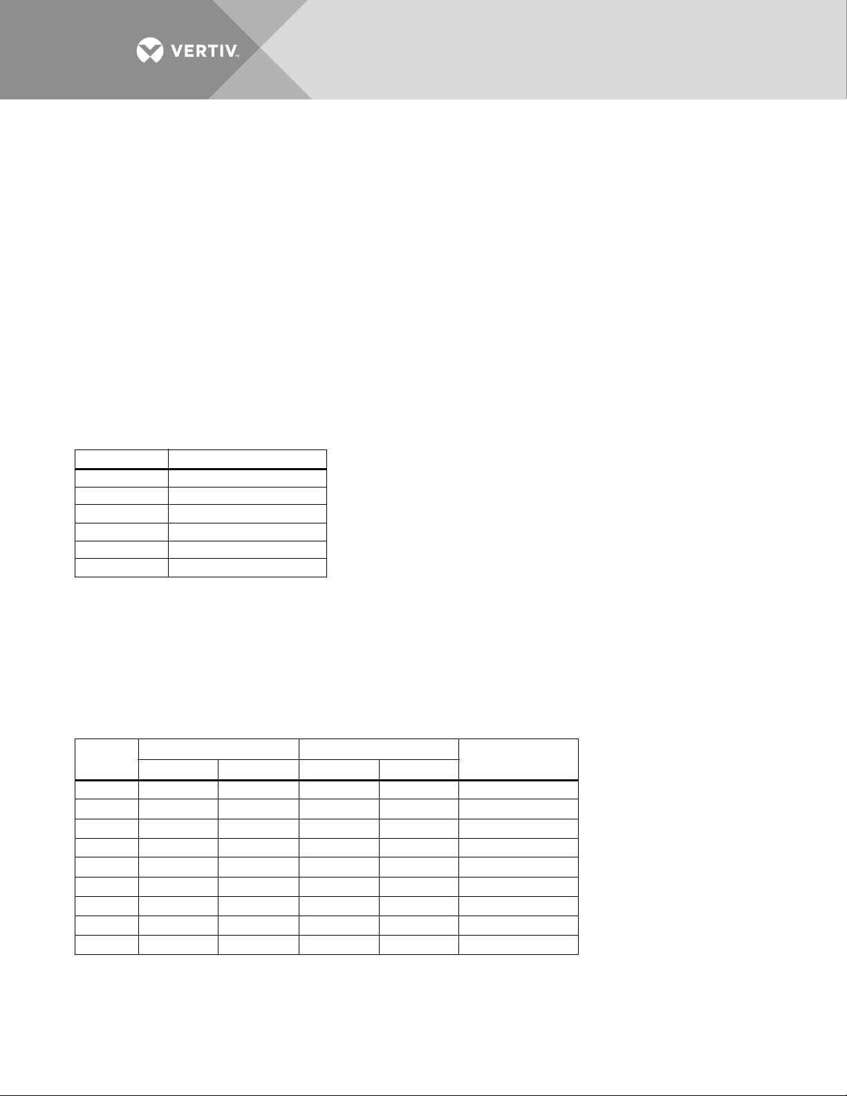
Check the unit size and weight. Refer to the cabinet drawings furnished with the unit for size and weight. Typical
cabinet dimensions are shown in Figures 7 through 22. Typical unit crated weights are:
Table 1 Shipping weights (typical)
Model Weight, lb. (kg)
250A 3813 (1733)
400A 4808 (2185)
600A 5892 (2678)
800A Module A* 4180 (1900)
800A Module B* 4723 (2147)
*800A ships on two separate pallets
Plan the route. Review the route over which the unit will be transported to its installation location to ensure that
all passages are large enough to accommodate the unit and support the weight.
Check for any non-negotiable corners or offsets in hallways. Before moving the unit to the intended location,
review 2.0 - Location Considerations.
1.2.2 Unit Preparation
The unit can be removed from the pallet before it is moved to its location.
Complete the following steps to properly remove the Liebert STS2/PDU from the shipping pallet:
1. Set the pallet in a level area with enough room to maneuver and remove the unit.
2. Remove the bolts holding the unit to the shipping pallet (located in the base of the unit).
3. Remove the shipping blocks from under the frame of the unit.
4. Use a forklift to raise the unit off the pallet and onto the floor. On the 250A unit ensure that the forklift is clear of the unit's
casters and stabilizing feet. Lift the unit from the rear.
5. Conduct an internal inspection of the unit. See the list in 1.3 - Internal Inspection.
1.3 Internal Inspection
After the Liebert STS2/PDU has been unpacked, conduct an internal inspection:
1. Verify that all items have been received.
2. If spare parts were ordered, verify their arrival.
3. After the Liebert STS2/PDU has been removed from the pallet, open the door and remove cabinet panels to check for
shipping damage to internal components.
4. Check for loose connections or unsecured components in the cabinet(s).
5. Check for any unsafe condition that may be a potential safety hazard.
After the Liebert STS2/PDU has been inspected and no problems are found, the unit can be moved to its
installation location. If using a forklift, remember to lift the unit from the rear.
Vertiv™ | Liebert® STS2/PDU™ User Manual | Rev. 6 | 10/2017 4

2.0 LOCATION CONSIDERATIONS
The Liebert STS2/PDU should be placed in a clean, cool and dry location. The 250A unit without an output
cabinet requires only front access for installation and maintenance. Both front and side access are required for
installation and maintenance of 400-800A units and 250A units with output cabinet. The output cabinet comes
factory-installed or either the right or left side, depending on how it was ordered. It cannot be moved from one
side to the other in the field.
Adequate space is required above the unit for conduit (if configured as such) and cooling air flow. This section
provides specific information for these considerations.
The unit is designed with top and bottom cable terminations to allow maximum flexibility in its installation. Units
with output inline panelboards are bottom exit only. If bottom cable entry and exit is used, sufficient cable
bending space must be provided by a raised floor or a floor stand.
For dimensions of each unit, see Figures 7 through 22. If your unit is equipped with an optional key lockout
switch, see Figures 13 through 21 for the location of that switch.
2.1 Recommended Minimum Service Clearances
The recommended service clearances are at the front and side, if equipped with output cabinet. The minimum
service clearance required by the National Electrical Code (NEC) Article 110-26 is 36 in. (91cm) for units with
voltages up to 150V to ground and 42 in. (107cm) for units with voltages over 150V to ground. Clearance of at
least 18 in. (46cm) is required above the unit for cooling air flow.
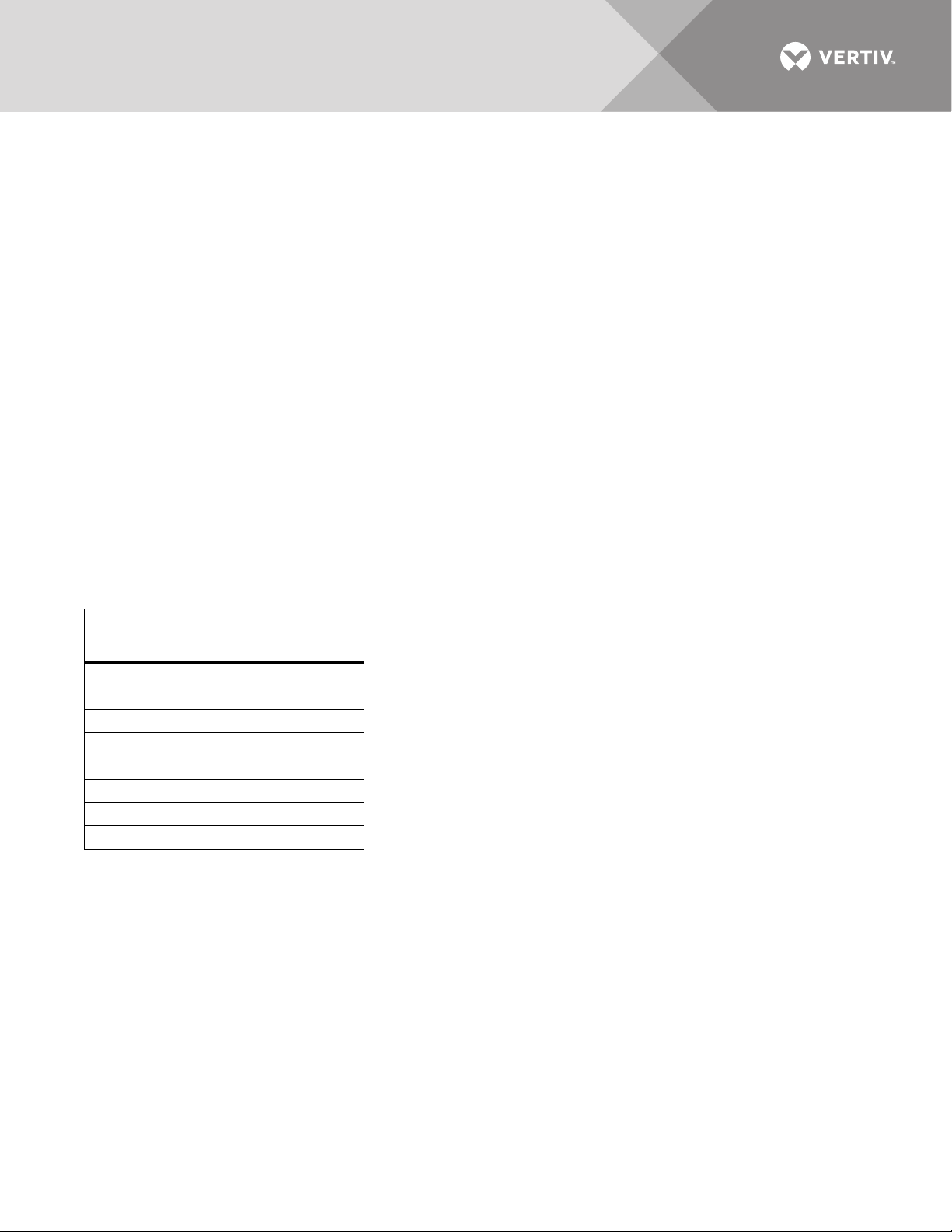
2.2 Heat Output
The unit produces minimal heat during normal operation.
Table 2 Heat output
Switch Size
250A 11,737 (3.44)
400A 19,295 (5.66)
600A 29,238 (8.57)
800A 39,238 (11.50)
Heat Output
BTU/Hr (kW)
2.3 Operating Environment
The unit is designed to be installed indoors where the ambient air temperature is in the range of 32° to 104°F
(0°C - 40°C) with a relative humidity of 0% to 95% non-condensing, up to an altitude of 4000 feet (1200 meters).
Vertiv™ | Liebert® STS2/PDU™ User Manual | Rev. 6 | 10/2017 5
2.4 Altitude
0
10,000
(3048)
9500
(2896)
9000
(2743)
8500
(2591)
8000
(2438)
7500
(2286)
6000
(1829)
5500
(1676)
7000
(2134)
6500
(1981)
5000
(1524)
4500
(1372)
4000
(1200)
100
86
88
90
92
94
96
98
Rating (%)
Altitude, Feet (M) Above Sea Level
0
10,000
(3048)
9500
(2896)
9000
(2743)
8500
(2591)
8000
(2438)
7500
(2286)
6000
(1829)
5500
(1676)
7000
(2134)
6500
(1981)
5000
(1524)
4500
(1372)
4000
(1200)
104.0 (40)
86.0 (30)
87.8 (31)
94.1 (33)
93.2 (34)
95.0 (35)
96.8 (36)
98.6 (37)
Maximum Ambient
Temperature, °F (°C)
Altitude, Feet (M) Above Sea Level
102.2 (39)
100.4 (38)
89.6 (32)
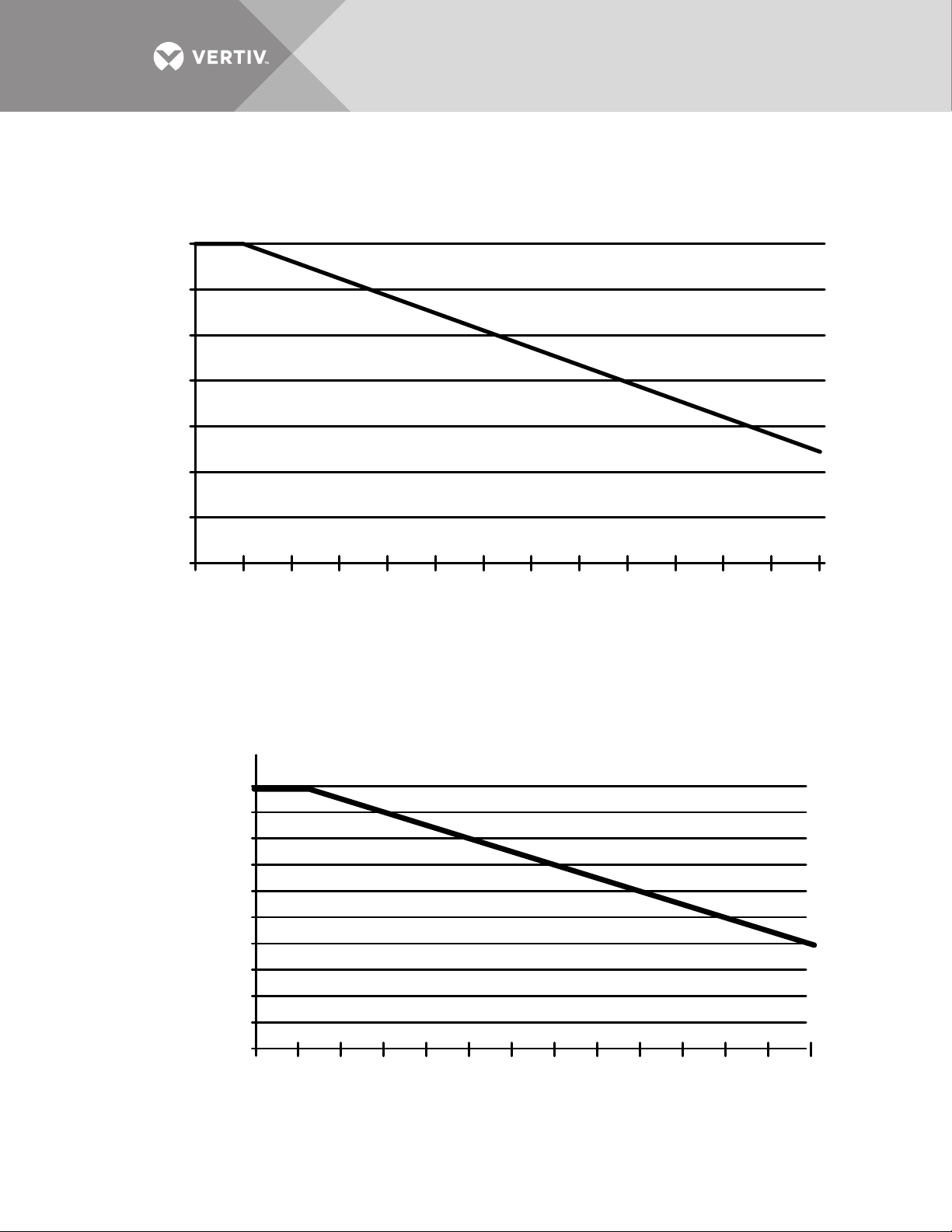
The standard units are designed for full load operation up to 4000 feet (1200m) above sea level. See Figure 1 for
recommended deratings for altitudes greater than 4000 feet (1200m).
Figure 1 Recommended derating for high altitude operation
Operation at full load at a higher altitude can be accommodated in ambient temperatures less than 104°F (40°C)
ambient. Figure 2 shows the maximum allowable ambient temperature for full load operation at altitudes above
4000 feet (1200m).
Figure 2 Maximum ambient temperature for full load operation at higher altitudes
Vertiv™ | Liebert® STS2/PDU™ User Manual | Rev. 6 | 10/2017 6

3.0 LOCATING THE LIEBERT STS2/PDU
This section provides instructions for leveling the Liebert STS2/PDU and anchoring the unit to the floor, should
that be required.
3.1 Anchoring the Unit to the Floor
The Liebert STS2/PDU can be anchored to the concrete floor to ensure stability for the unit in the event of
seismic activity.
3.2 Positioning the 250A Only Liebert STS2/PDU Without Anchoring
The 250A Liebert STS2/PDU is furnished with casters and stabilizing feet. After final positioning of the unit,
adjust the stabilizing feet located in each corner of the frame base to stabilize the unit.
For stabilizing feet details, see Figures 7 through 11.
Vertiv™ | Liebert® STS2/PDU™ User Manual | Rev. 6 | 10/2017 7

4.0 POWER AND CONTROL WIRING
WARNING
Risk of electric shock. Can cause injury or death.
This unit is supplied by more than one power source. The unit contains hazardous voltages if any of the
input sources are on, even when the unit is in bypass. To isolate the unit, turn off and lock out all input
power sources.
Verify that all input power sources are de-energized and locked out before making connections inside
unit.
Lethal voltages exist inside the unit during normal operation. Only qualified service personnel should
perform maintenance on the Liebert STS2/PDU.
All power and control wiring must be installed by a licensed, properly trained and qualified electrician. All
power and control wiring must comply with the National Electrical Code and all applicable local codes.
The input power busbars are accessible through the front of the unit. Liebert’s 250A units have PEM nut inserts
designed to allow one-handed tightening. Busbars in the 400-800A units are supplied with holes to
accommodate two-hole lugs.
Cables can be installed through the top or bottom of the unit through removable conduits plates. Units with
output inline panelboards are bottom exit only for output cables.
Unless otherwise labeled, use the recommended tightening torque shown in Tab le 30.
See Figures 12 through 21 for wiring entrance locations.
4.1 Input and Output Power Connections
The input power connections are made to the busbars provided inside the unit (see Figures 26 through 31).
These busbars are accessible through the front of the unit.
Output power connections are handled two different ways, depending on the type of distribution used. Power
connections on standard units with an output breaker are made to the busbars inside the unit. These busbars
are accessible through the front on 250A units and on the side on 400-800A units. See Figures 26 through 31
for details on the busbars. Power connections on units with panelboard distribution are made directly to the
panelboard breakers. Busbars are provided in the output cabinet for ground and neutral connections.
WARNING
Risk of electric shock. Can cause injury or death.
Verify that all input power and control circuits are de-energized and locked out before making
connections inside unit.
The two input power feeds (sources) to the Liebert STS2/PDU should be from two independent sources to avoid
a common source failure.
To ensure proper operation of the Liebert STS2/PDU, the two input sources must be the same nominal voltage
level and phase rotation.
For uninterrupted automatic transfer, the two input sources should be synchronized within 15 degrees.
NOTICE
The input sources to the Liebert STS2/PDU must be grounded-wye sources. Input sources other than solidly groundedwye sources may cause damage to the switch.
The Liebert STS2/PDU is designed for operation with three-wire, solidly grounded sources only.
Vertiv™ | Liebert® STS2/PDU™ User Manual | Rev. 6 | 10/2017 8
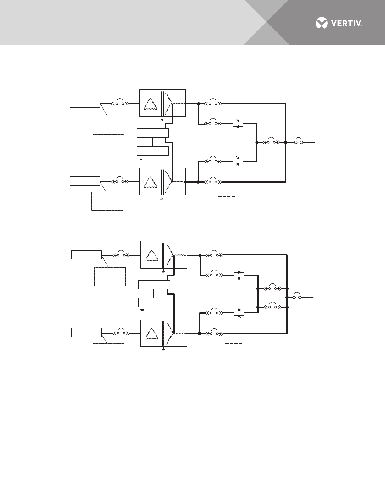
See Figures 3 through 6 for typical one-line diagrams. Refer to Figures 26 through 31 for electrical field
connections on all units.
Figure 3 Typical Liebert STS2/PDU, one-line diagram
Source 1
Source 2
CB6
Surge
Suppression
Optional
CB7
Surge
Suppression
Optional
Transformer 1
Neutral
Ground
Transformer 2
CB4
CB1
CB2
CB5
SS1
CB3
SS2
Field-Supplied Wiring
PSP12006
Rev. 1
Figure 4 Typical Liebert STS2/PDU, one-line diagram, with dual static switch output circuit breakers
(not available on 250A units)
Source 1
CB6
Surge
Suppression
Optional
Transformer 1
Neutral
Ground
CB4
CB1
CB2
SS1
SS2
CB3
CB3A
Breaker
Output
Breaker
CB8
Output
CB8
Source 2
CB7
Surge
Suppression
Optional
Transformer 2
CB5
Field-Supplied Wiring
PSP12007
Rev. 1
Vertiv™ | Liebert® STS2/PDU™ User Manual | Rev. 6 | 10/2017 9
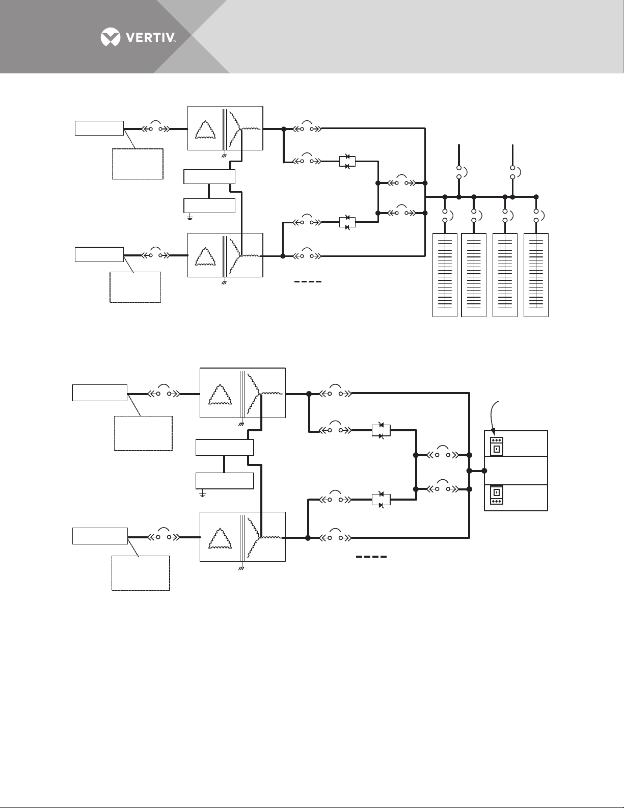
Figure 5 Typical Liebert STS2/PDU, one-line diagram, with inline distribution, dual static switch output circuit breakers
Source 1
Source 2
CB6
Surge
Suppression
Optional
CB7
Surge
Suppression
Optional
Transformer 1
Neutral
Ground
Transformer 2
CB4
CB1
CB2
CB5
SS1
SS2
Field-Supplied Wiring
PSP12003
Rev. 3
CB3
CB3A
Subfeed 1
Optional
CB12
CB8 CB9 CB10 CB11
42-Pole Distribution
Panelboard, Typical
Subfeed 2
Optional
CB13
Figure 6 Typical Liebert STS2/PDU, one-line diagram, with I-Line distribution, dual static switch output circuit breakers
Source 1
CB6
Surge
Suppression
Optional
Transformer 1
Neutral
CB4
CB1
SS1
Output
Breaker(s)
CB3
CB3A
I-Line Panelboard
CB7
Ground
CB2
CB5
SS2
Source 2
Surge
Suppression
Optional
Transformer 2
Field-Supplied Wiring
PSP12001
Rev. 2
The input and output power wire size should be based on the overcurrent protection device, observing the NEC
and local codes.
Vertiv™ | Liebert® STS2/PDU™ User Manual | Rev. 6 | 10/2017 10
The Liebert STS2/PDU output power, ground and neutral busbars accommodate a wide range of wire sizes. The
Liebert STS2/PDU busbars accommodate standard two-hole lugs.
Table 3 Input/output conduit plate specifications
Rating
250A
400-600A
800A
Maximum Number
of Conduits Size, in.
12 2"
82-1/2"
63" or 3-1/2"
6 2"
4 2-1/2" or 3"
62-1/2"
53" or 3-1/2"
4.2 System Grounding
Equipment grounding—Grounding is primarily for equipment and personnel safety, although proper grounding
also enhances equipment performance.
All input and output power feeds must include an equipment grounding means as required by the NEC and local
codes.
An insulated equipment ground conductor is recommended to run with each input and output power feed. The
equipment ground conductors should be at least the minimum size conductor per the NEC based on the
upstream overcurrent protection device.
WARNING
Risk of electric shock. Can cause injury or death.
If conduit is used as a grounding means, adequate electrical continuity must be maintained at all conduit
connections. Using isolating bushings with a metal conduit can be a safety hazard.
4.3 Control Wiring Connections
No control wiring is needed on the standard Liebert STS2/PDU. Certain options and remote monitoring
configurations require external control wiring. See 6.0 - Options for details.
The customer must supply control wiring to the Liebert STS2/PDU for connection to any monitoring or
communication options. Top and bottom removable conduit plates are provided for control wiring conduit.
Control cables can be installed through the top or bottom of the unit through removable control conduit plates.
A top hat is provided on the 400-600A units for connecting the top entry control wiring conduits (see
Figures 13 through 21). The top hat is turned upside down and ships inside the unit. It must be removed from the
unit and flipped 180 degrees before being reinstalled (see Figure 49). The control wiring top hat does NOT
contain any knockouts for conduit. The installer must drill the appropriate-sized holes for the conduit before
attaching to the top of the Liebert STS2/PDU.
See Figures 47 and 48 for arrangement of optional cards.
Vertiv™ | Liebert® STS2/PDU™ User Manual | Rev. 6 | 10/2017 11
4.4 Remote Source Selection Wiring
An optional Remote Source Selection board may be installed in your Liebert STS2/PDU. This board is installed in the
same bay as the communications options. See Figures 47 and 48 for the location of these options. See Figure 55 for
information on the control wiring for the Remote Source Selection option.
The Remote Source Selection allows you choose the preferred input source from a remote location.
Terminal connections allow the customer to remotely select a source to be the preferred source in the same
process as the local source transfer selection.
If both the input contacts are closed, the current selected preferred source shall be retained. If the unit’s
preferred source selection and Remote Source Selection are active at the same time,
the Liebert STS2/PDU follows the last request for a preferred source change, regardless of whether it was from
the local or Remote Source Selection controls.
A six pin terminal block provides the Remote Source Selection connections. Two pairs of wires are used from the
switch to trigger the source selection. You can select the type of switch used for this remote control.
Connections are made to four of the connections, using Form A dry contacts. The contacts are numbered left to
right:
Table 4 Remote source selection terminal block
Contact
1Source 1
2 Isolated ground
3Source 2
4Isolated Ground
5 DO NOT USE
6 DO NOT USE
Connection
See 10.3 - Enabling Remote Source Selection for instructions on enabling the Remote Source Selection option.
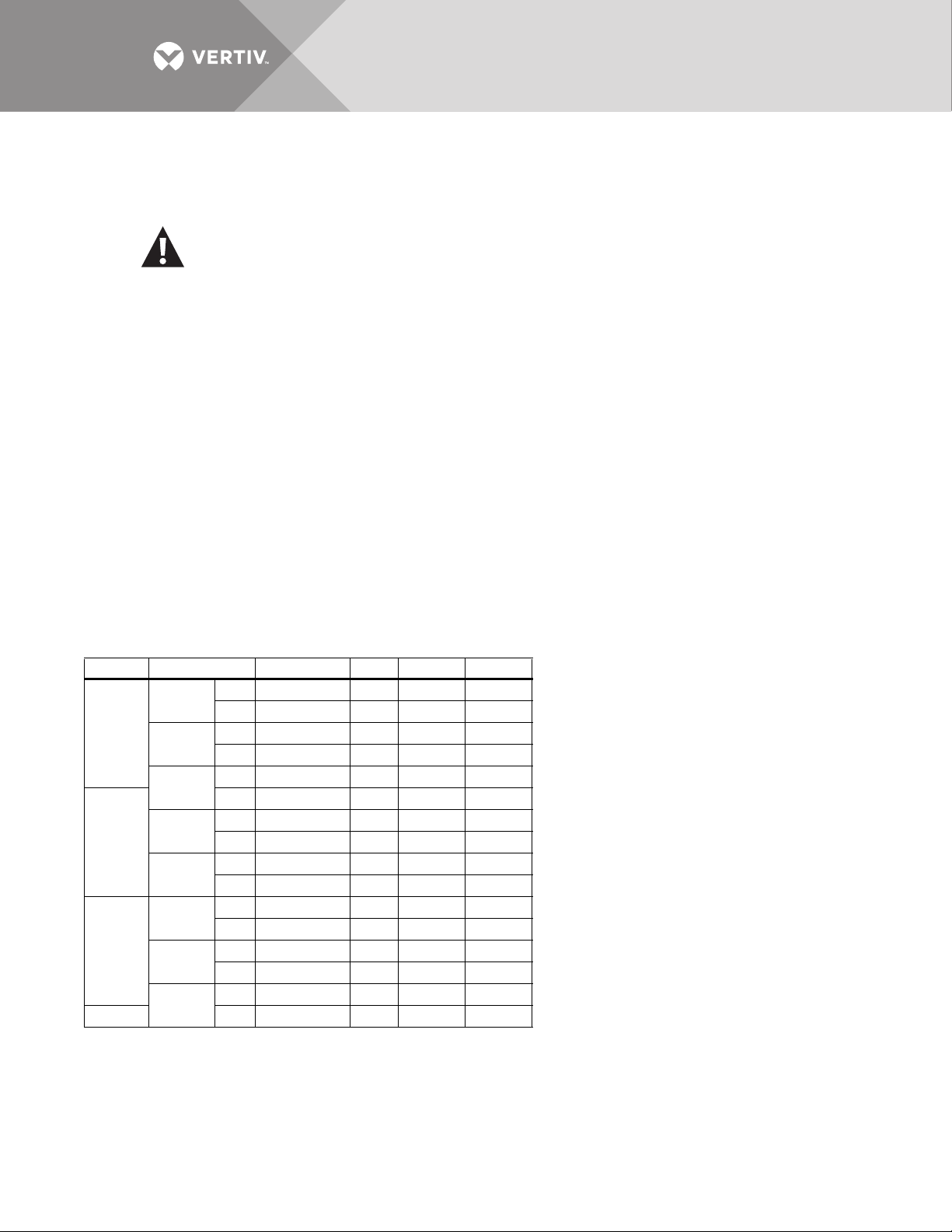
4.5 Power Supply
The Liebert STS2/PDU is supplied with redundant power supplies that are designed to operate from a voltage
range of 200V to 600V. The unit is set at the factory to match the nameplate voltage. Field adjustments are not
necessary. If the unit needs to operate at a voltage other than what is listed on the nameplate, contact Vertiv
Services or your local Vertiv representative. Tab le 5 provides transformer tap information.
Table 5 Terminal block 1 and terminal block 2 wire connections
Connect Connect
Vol tag e
200 1 9 1 9 1-7
220 2 12 2 12 6-8
380 1 8 1 8 2-7
415 1 10 1 10 4-7
600 1 12 1 12 6-7
208 1 10 1 10 1-7
240111111 1-7
400 1 9 1 9 3-7
480 1 11 1 11 5-7
Jumper BetweenF1 TB1-XX F2 TB1-YY F3 TB2-XX F4 TB2-YY
NOTICE
Using Tab le 5 , ensure that the wiring for the control transformers matches the input voltage for the unit.
Improper wiring could result in blown fuses.
Vertiv™ | Liebert® STS2/PDU™ User Manual | Rev. 6 | 10/2017 12
5.0 OUTPUT POWER WIRING
The Liebert STS2/PDU standard model is provided with a circuit breaker for connecting to the load or a remote
distribution cabinet. Other distribution configurations are available.
The three main types of distributions available for the Liebert STS2/PDU are:
•Output Breaker
• Inline Panelboards—two panelboards (84 poles) on 250A units and four panelboards (168 poles) on 400-800A units.
Square D
•SquareD I-Line
to 400A breakers are available on 800A units.
For other optional distribution methods, contact your local Liebert representative or call 1-800-LIEBERT.
The Liebert STS2/PDU distribution may be mounted on either the right or left side at the customer’s option.
Location of output conduit connections is affected by the location of the output cabinet. See
Figures 8, 9, 12, 13, 16 and 17 for wiring a right-side distribution configuration and Figures 10, 11, 14, 15, 18 and 19
for wiring a left-side distribution configuration. See Figures 23 through 44 for wiring.
See Table 6 for wiring the various output options.
5.1 Customer Connections
The customer is responsible for connections from the Liebert STS2/PDU distribution to the connected load,
either directly or through remote distribution cabinets.
Table 6 Distribution configurations
Distribution Type
Output Breaker
Inline Panelboards
I-Line (Square D) Figure 32
®
and General Electric panelboards are available to accommodate bolt-in or plug-in breakers.
®
Panelboard—designed to accommodate up to 10 plug-in breakers from 100A to 250A. Additionally, 300A
For Details See
Electrical Output
Field Connections
250A Figure 23
400-600A Figure 33
800A Figure 35
250A Figure 30
400-800A Figure 31
Vertiv™ | Liebert® STS2/PDU™ User Manual | Rev. 6 | 10/2017 13
6.0 OPTIONS
This section discusses the options available for the Liebert STS2/PDU. The communications options are also
discussed in 12.0 - Communication Interfaces.
WARNING
Risk of electric shock. Can cause injury or death.
All options must be installed by Vertiv Services or Vertiv factory-authorized service provided by a Vertiv
distributor. The option area and customer control cable area contain hazardous voltages if any of the
input sources are on, even when the unit is in bypass. Turn Off all power sources before installing
customer control cables to any option.
6.1 Programmable Relay Board
The programmable relay board (PRB) provides a means to trigger an external device when an event occurs in
the Liebert STS2/PDU. Each PRB has 8 channels. Each channel has two sets of Form-C dry contacts, rated 1A @
30VDC or 250mA @ 125VAC.
Any alarm or event may be programmed to any channel or channels. Up to ten (10) events may be programmed
to a relay. If multiple events are grouped to one relay, group the events logically to simplify troubleshooting when
an event is triggered. The same alarm or event may be programmed to more than one channel. Up to two
programmable relay boards can be installed in the Liebert STS2/PDU for a total of 16 channels. Programming is
performed through the touchscreen.
See Configuring the Programmable Relay Board Settings on page 109 for default settings and instructions
for reconfiguring the relays. See Figures 47 and 48 for the location of the PRB. See Figure 50 for wiring details.
Table 7 provides the PRB pin-out.
Table 7 Programmable relay board pinout
Channel Pin No. C N.C. N.O.
CH1
TB1
TB2
TB3
TB4
Key: N.O. = Normally Open; N/C. = Normally Closed; C = Common
Note: Pin 16 not used on TB1, TB2 and TB3.
CH2
CH3
CH4
CH5
CH6
CH7
CH8
A1-3 12 3
B4-6 45 6
A7-9 78 9
B 10-12 10 11 12
A 13-15 13 14 15
B1-3 12 3
A4-6 45 6
B7-9 78 9
A 10-12 10 11 12
B 13-15 13 14 15
A1-3 12 3
B4-6 45 6
A7-9 78 9
B 10-12 10 11 12
A 13-15 13 14 15
B1-3 12 3
Vertiv™ | Liebert® STS2/PDU™ User Manual | Rev. 6 | 10/2017 14

6.2 Input Contact Isolator Board
The Input Contact Isolator Board (ICI) provides a Liebert STS2/PDU module interface for up to eight external
user alarm or message inputs to be routed through the Liebert STS2/PDU’s alarm network. The eight contacts
are normally open dry contacts. When a contact closes, an event is triggered.
The Input Contact Isolator options are configured through the Input Contact Isolator dialog box, which is
accessed from the Comm Option dialog box on the touchscreen. You also can program the alarm messages
through this dialog box. See Configuring the Input Contact Isolator Settings on page 107 for instructions on
configuring the connections.
See Figures 47 and 48 for the location of the ICI. See Figure 51 for wiring details.
6.3 Comms Board
The Comms Board provides a communication interface to Liebert SiteScan®, site monitoring product and/or an
external modem. Liebert SiteLink®-12 or Liebert SiteLink®-4 is required for Liebert SiteScan to communicate with
the Liebert STS2/PDU.
The Comms Board is equipped with an RS-422 communication port for communication to a Liebert SiteScan
monitoring system using a 2-wire twisted pair for reliable communication up to 1000 meters (3281 feet).
Information available from the RS-422 port includes the present switch status information, all monitoring
parameters and all active alarms.
The Comms Board is equipped with a modem interface for remote reporting of the present switch status
information, alarm history information and the history of status screens that are triggered upon a major alarm
event. The monitoring system software also supports an auto-dial feature that allows the system to automatically
dial programmed phone numbers by way of a modem to report designated alarm conditions.
Programming the Comms Board is performed through the touchscreen. See Comm Options on page 105 for
details.
See Figures 47 and 48 for the location of the Comms Board. See Figure 52 for information on the control wiring.
6.4 Liebert IntelliSlot™ Web/485 Card With Adapter
A Liebert IntelliSlot Web/485 Card With Adapter (IS-WEB485ADPT) enables the Liebert STS2/PDU to
communicate to a network management system (NMS). The card provides the internal hardware and software to
communicate, via SNMP, to any I.P.-based Ethernet network through an RJ-45 connector using Category 5
cabling.
The Liebert IS-WEB485ADPT provides redundant paths for communications that make it possible to connect to
a Building Management System (BMS) using Modbus, while simultaneously communicating to a NMS through
SNMP. A terminal block provides the connection to Modbus.
See Figures 47 and 48 for the location of the Liebert IntelliSlot Web/485 Card With Adapter. See Figure 53 for
control wiring information.
If you have questions about the Liebert IS-WEB485ADPT, refer to the user guide SL-52615, available at Vertiv’s
Web site, www.vertivco.com
Vertiv™ | Liebert® STS2/PDU™ User Manual | Rev. 6 | 10/2017 15

6.5 Remote Source Selection
The Remote Source Selection allows the preferred input source to be chosen from a remote location. A user
supplied normally open dry contact allows the user to remotely select a source to be the preferred source in the
same process as the local source transfer selection.
If both the input contacts are closed, the current selected preferred source shall be retained. If the unit’s
preferred source selection and Remote Source Selection are active at the same time,
the Liebert STS2/PDU follows the last request for a preferred source change, regardless of whether it was from
the local or Remote Source Selection controls.
See 10.3 - Enabling Remote Source Selection for instructions on enabling the Remote Source Selection.
See Figures 47 and 48 for the location of the Remote Source Selection option.
See 4.4 - Remote Source Selection Wiring and Figure 55 for information on the control wiring.
6.6 Key Lockout Switch
The key lockout switch activates a software lockout of the touchscreen to prevent manual transfers and
configuration changes. When locked out, the touchscreen becomes a read-only display. A key is needed to do
manual transfers or change settings.
The alarm silence button is not disabled when in the lockout position.
The switch is located on the front of the unit next to the display; it is behind the front door but can be operated
without opening the front door. See Figures 20 through 22 for the key lockout switch location on each unit.
See 13.2.1 - Security and Figure 64 for instructions on using the key lockout switch.
6.7 Static Switch Redundant Output Breaker
A plug-in, non-automatic circuit breaker is provided which allows redundancy in the static switch output power
path. The breaker is connected in parallel with the static switch output plug-in non-automatic circuit breaker.
6.8 Inline Panelboards
An output distribution cabinet with either Square D or General Electric inline panelboards with copper bus to
accept bolt-in or plug-in circuit breakers. Each panelboard is individually protected by a 225A, 3-pole panelboard
main circuit breaker.
Each panelboard includes a separate isolated neutral bus bar and a safety-ground bus bar for the neutral and
safety-ground connections for at least 42 output circuits.
6.9 I-Line Panelboards
An output distribution cabinet with one vertically mounted Square D I-Line panelboard with copper bus to
accept Square D three phase plug-in circuit breakers. The panelboard must be enclosed with an accent cover.
6.10 Subfeed Breakers
Breakers for feeding remote panelboard(s) or other loads. Available in ratings of 225A or 400A.
NOTE
Only available on units with inline panelboards. 400A breaker not available on 250A units.
6.11 K-Factor Transformers
U.S. Department of Energy compliant K20-rated double-shielded copper isolation transformer specially designed
to accommodate highly nonlinear loads in accordance with UL 1561 (in place of standard isolation transformer).
6.12 Surge Suppression System
A fused and monitored high-energy, 80 kAmp/phase surge suppression system by Control Concepts connected
to each input of the unit for superior surge suppression.
Vertiv™ | Liebert® STS2/PDU™ User Manual | Rev. 6 | 10/2017 16
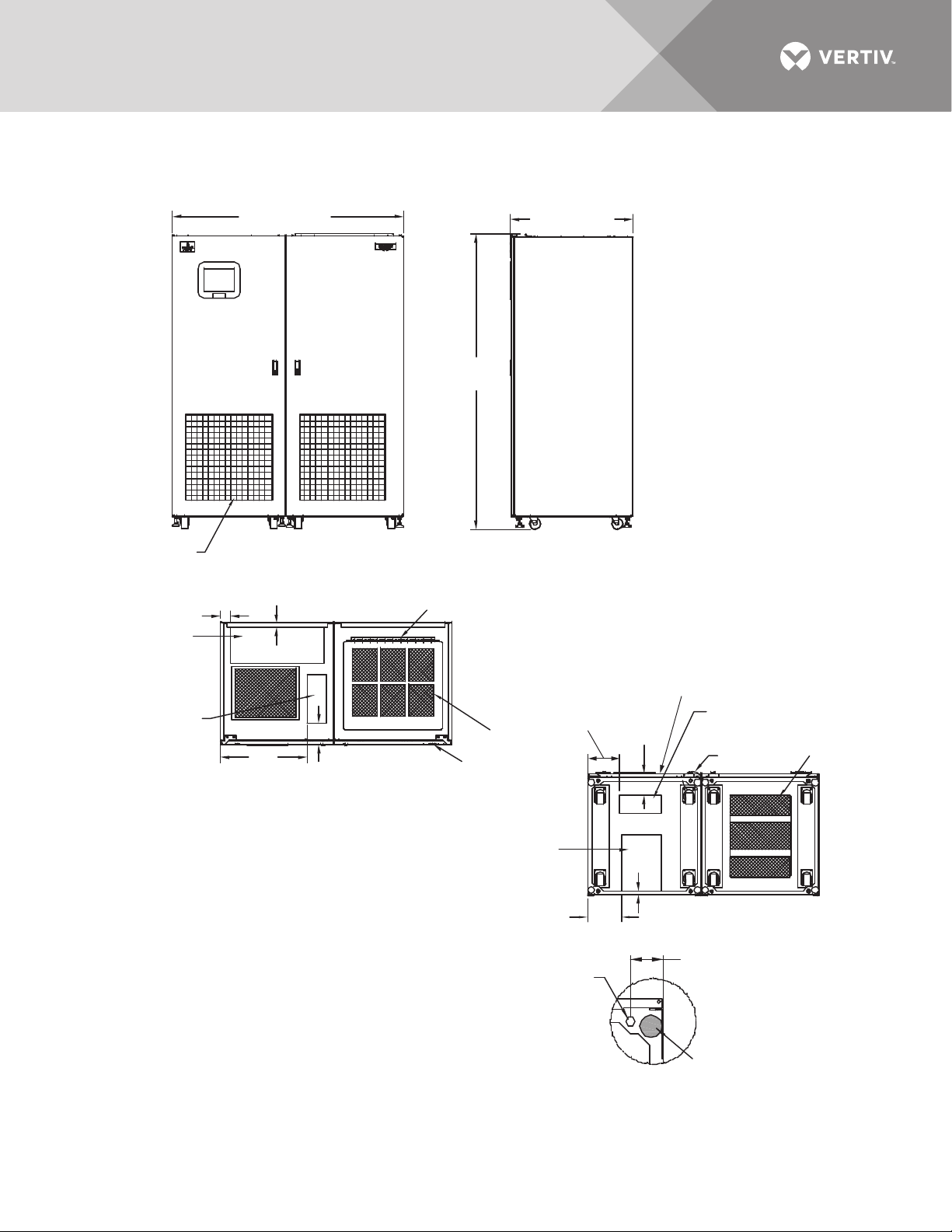
7.0 INSTALLATION DRAWINGS
22.8"
(579.1mm)
Air Intake
Air Intake Area
Do not block air
filter, typical
See Detail A
PSP11200
Rev. 4
Bottom Power
Conduit Entry
Area 14.8" x 10.4"
(375.9 x 264.2mm)
Top Power Conduit
Entry Area 24.4" x 9.4"
(619.8 x 238.8mm)
2.75" (69.8mm)
Typical
Stabilizing Foot
1. 18" (457mm) clearance above unit required for air exhaust
2. Installation and service access required in front only.
3. Approximate heat output: 11,737 BTU/Hr (3.44 kW).
4. Approximate weight: 3393 lb. (1542 kg)
5. Unit bottom is structurally adequate for forklift handling.
6. Keep cabinet within 15 degrees of vertical while handling.
7. Color: IBM off-white
8. Open door to replace air filter, disposable type,
size: 1"x25"x25" (25 x 635x635mm)
9. Threaded mounting holes (see Detail A) are provided for seismic
anchoring or floor stand. Mounting bolts must be threaded into the
unit mounting holes from underneath the unit base. If a floor stand
is used, the casters must rest on the floor stand to support the unit's weight.
10. Top and bottom cable entry available through removable access plates.
Remove, punch to suit conduit size and replace.
12mm Diameter
Threaded Mounting
Hole; 4 typically
See Note 9
Hinged Access Panel
To Input Breakers
Air Exhaust
120° Front Door Swing
All doors with
lift-off hinges
2.8" (71.1mm)
Top Control Conduit
Entry Area 12.8" x 5.1"
(325.1 x 129.5mm)
1.1"
(27.9mm)
Bottom Control
Conduit Entry
Area 11" x 4.6"
(279.4 x 116.8mm)
Front
8.4"
(213.6mm)
8.8"
(223.5mm)
5.6"
(142.2mm)
5.8"
(147.3mm)
TOP
RIGHT SIDE
FRONT
BOTTOM
Detail A
(Front of Unit
Shown without Side Panel)
1.1"
(28mm)
77.6"
(1971mm)
32.3" (820mm)
60.9 (1547mm)
Figure 7 Outline drawing, 250A Liebert STS2/PDU
Vertiv™ | Liebert® STS2/PDU™ User Manual | Rev. 6 | 10/2017 17
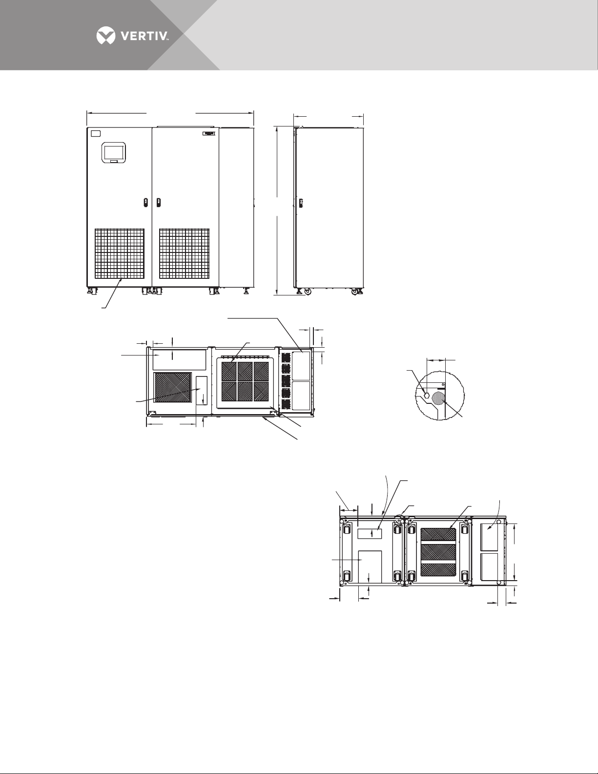
Figure 8 Outline drawing, 250A Liebert STS2/PDU with right side I-Line distribution
A
76.8 (1950mm)
77.6
(1970mm)
ir Intake Area
Do not block air
filter, typical
2.8" (71mm)
Top Input Power
Conduit Entry Area
24.4" x 9.4"
(620 x 239mm)
Top Control Conduit
Entry Area 12.8" x 5.1"
(325 x 130mm)
1.18" (457mm) clearance above unit required for air exhaust
2. Installation and service access required in front only.
3. Heat output: Approx. 11,737 BTU/hr (3.44kW).
4. Approximate weight: 3993 lb. (1815 kg).
5. Unit bottom is structurally adequate for forklift handling.
6. Keep cabinet within 15 degrees of vertical while handling.
7. Color: IBM off-white
8. Open door to replace air filter, disposable type, size: 1" x 25" x 25"
(25 x 635 x 635mm).
9. Threaded mounting holes (see Detail A) are provided for seismic
anchoring or floor stand. Mounting bolts must be threaded into unit mounting
holes from underneath unit base. If a floor stand is used, the casters must rest
on the floor stand to support the unit’s weight.
10. Top and bottom cable entry available through removable
access plates. Remove, punch to suit conduit size and replace.
FRONT
1.1"
(27.9mm)
Top Output
Conduit Entry Area
(2) 13.1" x 7.9"
(333 x 201mm)
5.6"
(142.2mm)
TOP
Air Exhaust
120° Front Door Swing
All doors with
lift-off hinges
Bottom Input Power
Conduit Entry
Area 14.8" x 10.4"
(376 x 264mm)
PSP11206
32.3" (820mm)
RIGHT SIDE
1.8" (46mm)
2.3"
(58mm)
Hinged Access Panel
To Input Breakers
12mm Diameter
Threaded Mounting
Hole; 4 typically
See Note 9
8.4"
(214mm)
(147mm)
8.8"
(224mm)
5.8"
1.1"
(28mm)
2.75"
(69.8mm)
Typical
Detail A
(Front of Unit
Shown without Side Panel)
Front
Bottom Control
Conduit Entry
Area 11" x 4.6"
(279.4 x 116.8mm)
See Detail A
BOTTOM
(101.6mm)
Stabilizing
Foot
Bottom Output
Conduit Entry Area
(2) 12.5" x 7.2"
(318 x 183mm)
Air
Intake
4"
26"
(660mm)
2.6" (66mm)
Rev. 2
Vertiv™ | Liebert® STS2/PDU™ User Manual | Rev. 6 | 10/2017 18
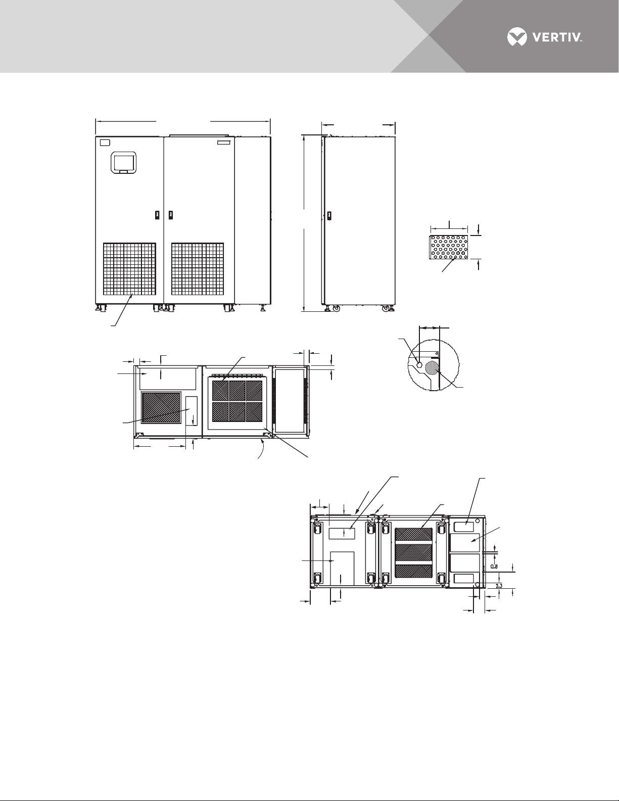
Figure 9 Outline drawing, 250A Liebert STS2/PDU with right side inline distribution
76.8 (1950mm)
Air Intake Area
Do not block air
filter, typical
2.8" (71mm)
Top Input Power
Conduit Entry Area
24.4" x 9.4"
(620 x 239mm)
Top Control Conduit
Entry Area 12.8" x 5.1"
(325 x 130mm)
1. 18" (457mm) clearance above unit required for air exhaust
2. Installation and service access required in front only.
3. Heat output: approx. 11,737 BTU/hr (3.44kW).
4. Approximate weight: 3993 lb. (1815 kg).
5. Unit bottom is structurally adequate for forklift handling.
6. Keep cabinet within 15 degrees of vertical.
7. Color: IBM off-white
8. Open door to replace air filter, disposable type, size:
1" x 25" x 25" (25 x 635 x 635mm).
9. Threaded mounting holes (see Detail A) are provided
for seismic anchoring or floor stand. Mounting bolts
must be threaded into unit mounting holes from
underneath unit base. If a floor stand is used, the
casters must rest on the floor stand to support the
unit's weight.
10. Top and bottom cable entry available through removable
access plates. Remove, punch to suit conduit size and replace.
FRONT
1.1"
(27mm)
22.8"
(579mm)
5.6"
(142.2mm)
Air Exhaust
TOP
120° Front Door Swing
All doors with lift-off hinges
Bottom Input
Power Conduit
Entry Area
14.8" x 10.4"
(376 x 264mm)
77.6
(1970mm)
2.1"
(53mm)
Hinged Access
Panel to Input
Breakers
(213mm)
(223.5mm)
PSP11207
Rev. 2
32.3" (820mm)
RIGHT SIDE
12mm Diameter
Threaded Mounting
Hole; 8 typically
See Note 9
1.7"
(43mm)
8.4"
5.8"
(223.5mm)
1.1"
(28mm)
8.8"
12.5"
(318mm)
0.88" Diameter
Typically 42 Places
Detail B
Detail A
(Front of Unit
Shown without Side Panel)
Bottom Control
Conduit Entry
Area 11" x 4.6"
Front
(279 x 117mm)
See Detail A
BOTTOM
2.6" (66mm)
2.75"
(69.8mm)
Typical
Air
Intake
8.1"
(206mm)
Stabilizing
Foot
Bottom Output
Subfeed Conduit
Entry Area
Typically 2 Places
8.3" x 4"
(211 x 102mm)
Bottom Output
Conduit Entry Area
Typically 2 Places
See Detail B
7.1" (180mm)
5.1" (130mm)
Vertiv™ | Liebert® STS2/PDU™ User Manual | Rev. 6 | 10/2017 19
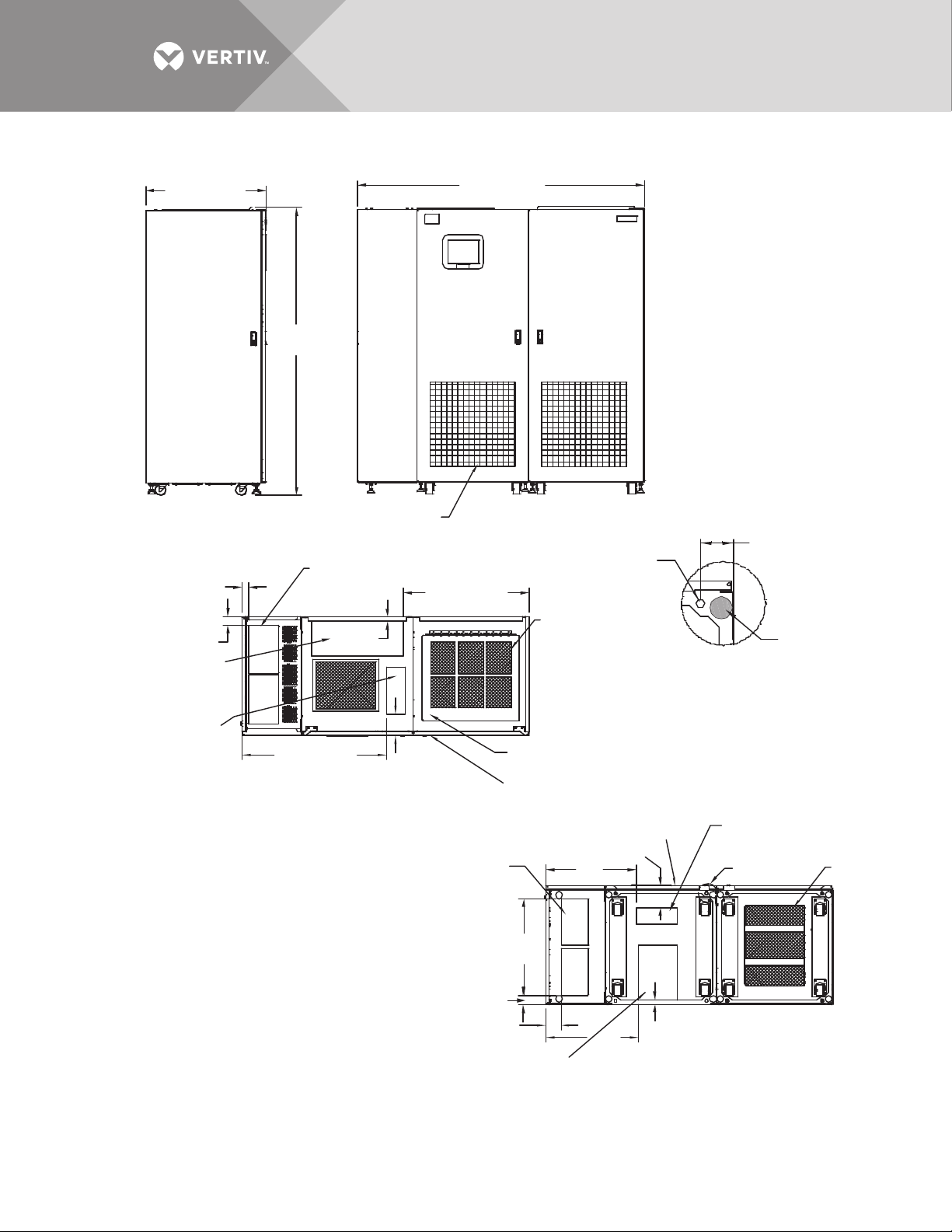
Figure 10 Outline drawing, 250A Liebert STS2/PDU with left side I-Line distribution
32.3" (820mm)
LEFT SIDE
1.8" (46mm)
2.3" (58mm)
Top Input Power
Conduit Entry Area
24.4" x 9.4"
(620 x 239mm)
77.6
(1970mm)
Top Output
Conduit Entry Areas
(2) 13.1" x 7.9"
(333 x 201mm)
Air Intake Area
Do not block air
filter, typical
1.1"
(27.9mm)
76.8 (1950mm)
33.7" (856mm)
FRONT
12mm Diameter
Threaded Mounting
Hole; 4 typically
See Notes 8 and 9
Air
Exhaust
2.75"
(69.8mm)
Typical
Stabilizing
Foot
Detail A
(Front of Unit
Shown without Side Panel)
Top Control Conduit
Entry Area 12.8" x 5.1"
(325 x 130mm)
38.7" (983mm)
5.6"
(142mm)
TOP
1. 18" (457mm) clearance above unit required for air exhaust
2. Installation and service access required in front only.
3. Heat output, approximately 11,737 BTU/Hr (3.44kW).
4. Approximate weight: 3993 lb. (1815 kg).
5. Unit bottom is structurally adequate for forklift handling.
6. Keep cabinet within 15 degrees of vertical.
7. Color: IBM off-white
8. Open door to replace air filter, disposable type, size: 1" x 25" x 25"
(25 x 635 x 635mm).
9. Threaded mounting holes (see Detail A) are provided for seismic
anchoring or floor stand. If a floor stand is used, the casters
must rest on the floor stand to support the unit’s weight.
10. Top and bottom cable entry available through removable
access plates. Remove, punch to suit conduit size and replace.
Bottom Output
Conduit Entry Area
(2) 12.5" x 7.2"
(318 x 183mm)
Hinged Access Panel
To Input Breakers
120° Front Door Swing
All doors with
lift-off hinges
26"
(660mm)
2.6" (66mm)
4" (102mm)
Bottom Input Power
Conduit Entry
Area 14.8" x 10.4"
(376 x 264mm)
24.2"
(615mm)
24.7"
5.8"
(147mm)
(27.9mm)
(627mm)
PSP11202
Rev. 2
Front
1.1"
BOTTOM
Bottom Control
Conduit Entry
Area 11" x 4.6"
(279.4 x 116.8mm)
See Detail A
Air
Intake
Vertiv™ | Liebert® STS2/PDU™ User Manual | Rev. 6 | 10/2017 20
 Loading...