

Vertiv Liebert SmartAisle2 User Manual

Liebert® SmartAisle2
User manual

Copyright by Vertiv Co. Ltd.
The content in this document is subject to change without notice. All rights, including rights of
translation, reproduced by printing, copying or similar methods, and even of parts, are reserved.
Violators will be liable for damages. All rights, including rights deriving from patent license or
registration of a utility model or design, are reserved. No part of this document may be reproduced
or transmitted in any form or by any means without the prior written consent of Vertiv Co. Ltd.
Notice
The purchased products, services, and features are stipulated by the contract made between Vertiv
Co., and the customer. All or part of the products, services, and features described in this document
may not be within the purchasing scope or the usage scope. Unless otherwise specified in the
contract, all statements, information, and recommendations in this document are provided "AS IS"
without warranties, guarantees or representations of any kind, either express or implied. The
information in this document is subject to change without notice. Every effort has been made in the
preparation of this document to ensure the accuracy of the contents, but all statements,
information, and recommendations in this document do not constitute a warranty of any kind,
express or implied.
Vertiv Co., Ltd.
China
Website:www.vertivco.com
E-mail: support@Vertivco.com
Customer service hotline: 4008876510
Asia-Pacific
Homepage: www.vertivco.com
E-mail: overseas.support@Vertivco.com
For Technical Support, users may contact the nearest Vertiv Co. local sales office or service center.
Styling used in the Guide
The styles used in this manual are defined in the following table:
Situation
Description
Warning/Danger/Caution
The Warning/Danger/Caution note indicates a hazardous or
potentially harmful situation that can result in death or
injury. It also indicates instructions that need to be adhered
to, failing which may result in danger and safety issues,
thereby having an adverse effect on the reliability of the
device and security. Even for practices not related to physical
injury, the content under the Warning heading is used for
precautions which need to be taken which, otherwise, could
result in equipment damage, performance degradation, or
interruption in service.
Note
The Note section indicates additional and useful information,
including tips and tweaks. It also calls attention to best
practices and industry-best protocols that are standardized
and help make maximum utilization of the resources at
hand. Helpful information related to the mainstream content
also comes under the Note heading helping the users get to
grips with the definitions, concepts, and terminologies used
in the manual.
Version History
Issue
Revision Date
BOM
Changes
1.0
=
---
Safety Precautions & Measures
In this section, the safety measures related to the entire SmartCabinet™ unit will be explained in
detail.
Read the manual prior to installation and operation of the unit. Only qualified personnel
should move, install, or service this equipment.
The user reads and takes into account all the precautions, compliance, and safety measures
before working on the equipment. The unit control must be used exclusively for the purpose
which it is intended for; the manufacturer takes no liability for incorrect use or a
modification to the unit control.
Please read this manual carefully before installing, maintaining and troubleshooting;
especially the Warning/ Danger/ Caution information in the User Guide. Apart from the User
Guide, also pay attention to the warning labels on the unit and its components.
This manual is retained for the entire service life of the machine. The user must read all the
precautions, danger, warnings, and cautionary measures mentioned in the manual prior to carrying
out any operations on the machine.
Adhere to all the notes, warnings, cautions, potential dangers, and precautions mentioned in the
manual. Read this manual before carrying out any operation on the unit.
The Warnings/Danger/Cautions/Precautions/Notes do not represent the entire safety points to be
observed and only supplementary in nature. This product is tailored for industrial, commercial, or other
professional units (such as manufacturing, electrical, and instrumentation setups) and not meant for
purposes related wholly to individuals without the credentials. The purpose of the design is well defined
and therefore, the manufacturers do not assume any responsibility for any incorrect usage. Strict
adherence to the norms and usage should be observed. In case of any improper use or modifications,
the warranty will be void; handle with care, especially the key to the product must be allocated to the
service personnel responsible for maintenance.
General Safety Instructions
Use the tools with an insulation handle.
Wear rubber gloves and safety shoes.
Avoid placing tools and metal objects on the battery surface
Remove the watches, rings, or any metal objects.

Only after all the power is disconnected, operate on the inner components of the product.
Before operating on the inner components for any maintenance, you must switch off the
mains breaker and all UPS power.
After an alarm occurs through product monitoring platform, the need for timely find the
cause, treatment failure, to avoid more trouble, damage.
Risk of electric shock
There is a risk of an electric shock which may lead to personnel injury or death: To prevent or avoid
such a situation, the following points must be taken into account:
Disconnect the control box and remote power supplies prior to working on the product.
Local codes, regulations, and protocols may vary from region to region. Therefore, adhere
to all these local protocols and rules prior to installing, operating, or servicing of the
machine.
Read all the instructions, ensure that all the parts and components are included, and check
the nameplate to ascertain that the voltage matches the available mains; Proceed with the
installation, maintenance, troubleshooting, and operating on the machine only after going
through the preceding steps.
This product is suitable only for the TT and TN type power grid; it doesn’t apply to the IT
type power grid.
Finally, read all the labels on the unit and its components before operating on those
components during installation and maintenance. The warnings and cautionary measures
mentioned in this manual are supplementary and therefore, the measures listed on the
labels of the components and the unit must be considered strictly before any operation.

PART I
Introducing SmartAisle
1 Introduction
SmartAisle2 is an intelligent, integrated infrastructure in a self-contained line-up solution that is
easy to deploy and tailored for large data centers and computer rooms. All data centers have
distinct operation and business objectives. Balancing the data center practices for capacity, space
utilization, availability, and efficiency has been tedious owing to the ever-increasing demand in the
IT space.
Enter SmartAisle2 – an enclosed complete data center solution (referred to as SmartAisle) in an
indoor environment. With Precision cooling, UPS, power management, monitoring and control
technologies and fire suppression integrated into a holistic enclosed system, this smart solution is
ideally suited for environments where dedicated IT room improvements are neither practical nor
cost-effective. It is flexible as it can be placed unobtrusively into workspaces without the clutter or
bulk associated with these kinds of solutions. It is highly effective, economical, interoperable, and
makes use of the existing infrastructure or whitespace, avoids expensive room upgrades along with
the optional fire suppression system- all in one enclosed solution. This top-notch modular
enterprise-grade solution is unique and brings together industry-best practices and latest
technologies to enable streamlined management in a compact footprint.
It is an ideal solution tailored for 19” rack hardware device, including servers, voice data, the
internet network equipment, cabinets, closure assembly and power supply, cooling, monitoring
equipment, equipment for bearer cabinets and is best suited for large data centers.
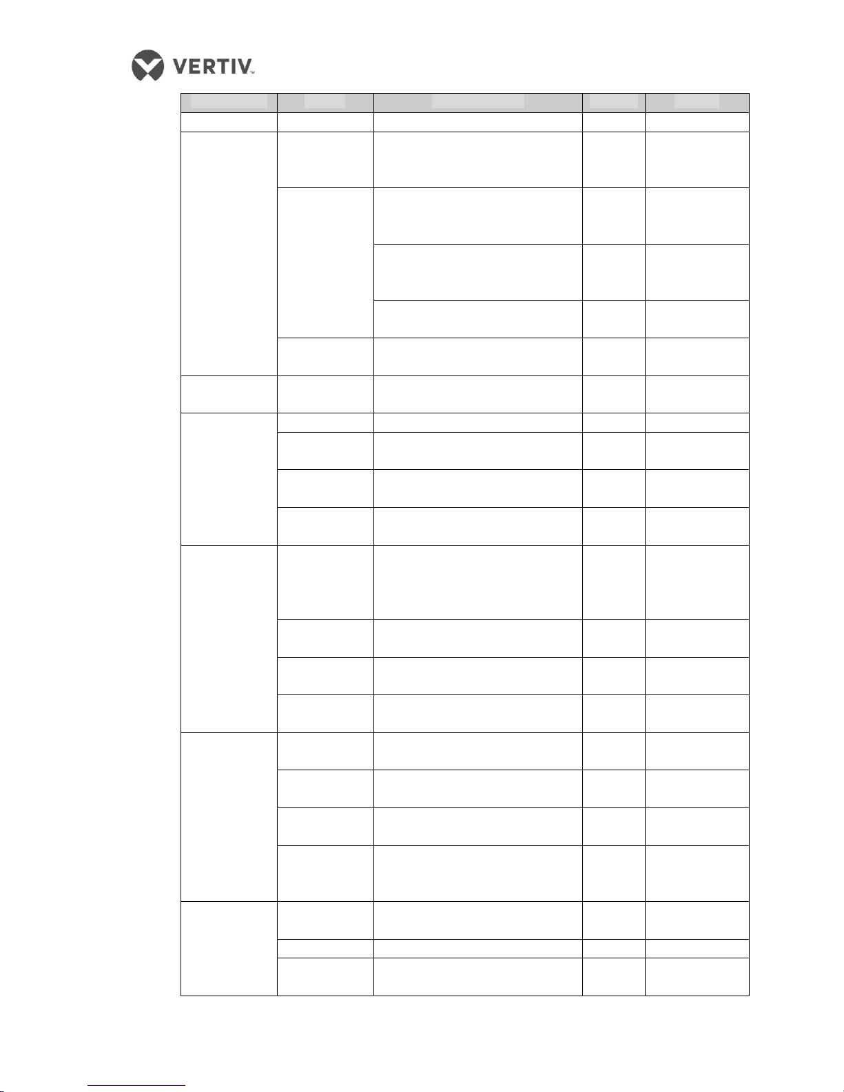
1.1 Configuration Specification for SmartAisle
The typical configuration of the SmartAisle solution is shown in Table 1-1.
Table 1-1 Configuration
Parameter
Specifications
Size
Corridor width
1200mm
Machine external dimensions
See Section 1.5.3
Overall key
indicators
Density levels
Low-density
Power Architecture
Centralized power supply
Cooling architecture
Air cooled DX based row cooling units,
independent cooling modules
Structured Cabling
Column header network wiring closet
Fire architecture
External fire, borrow building
The total number of U-bit single
module
966 (single cabinet 42U, including the
network cabinet)
Redundant power supply
2N
The average power consumption of
a single cabinet
4kW
IT power consumption single
module
92kW
Single refrigeration module
105kW
Altitude
Less than 1000m (air conditioning derating
more than 1000m)

Mounting
Raised floor or ground installation
Voltage
standard
Voltage
(380 ~ 415) Vac ± 10%, 3N ~
frequency
50Hz / 60Hz
Colour
Pantone 877C + RAL7021
1.2 Salient Features
SmartAisle has several distinct features that make it an outstanding utility for mid-tier and large
data centers.
Efficiency
Close control of precision air cooling with an exact match with the thermal load using a variable
capacity system that provides focussed cooling with high energy savings
Intelligent Monitoring
Enables supervision and management of the environment, equipment, electric doors, roof and
alarm linkage intelligent control system in a centralized manner for the administrator.
Convenient Operations & Maintenance
Use of electric door anti-pinch safety and access control systems improves the user comfort and
safety experience.
Security Management
Use of electric doors and roof-emergency response system that enables enhanced security
feature.
Intelligent Lighting
The integrated 3-color bright lights, set display, illumination and easy-to-understand interface
to facilate appropriate space lighting needs.
Human Machine Interface
A 15-inch large control panel which is quite intuitive and advanced enables administrators and
facility managers to visualize the entire system operation in real time
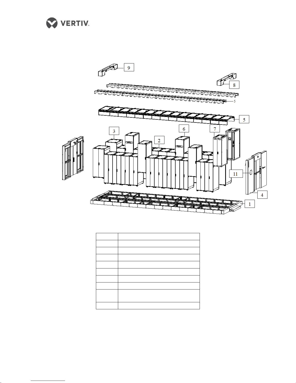
1.3 Appearance and Components
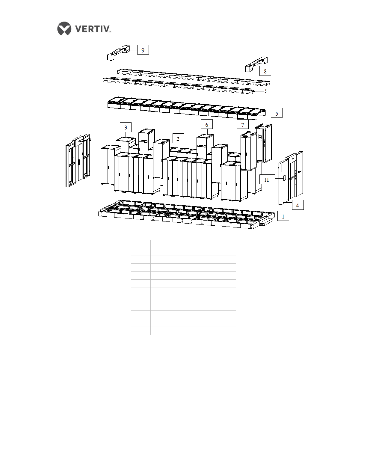
The bifurcation of all components that constitute the SmartAisle solution is depicted in the
following figure (Refer Figure 1-1);
Figure 1-1 SmartAisle layout diagram
1
Base
2
Server Cabinet
3
Network Cabinet
4
Access door
5
Top Plate
6
A/C Column
7
Distribution Cabinet
8
Strong wire passage groove
9
Power cable trunking; copper
and fibre cable tray
11
Control panel

Configuration of Components
The Base enables achieving a common ground to mount the entire machine equipment,
eliminating the need to set up static flooring and providing pipeline space.
The cabinet is an ideal utility for 19 "rack-mount hardware, including servers, voice, data,
Internet, and other network equipment.
Closure assembly (Access door & Roof) enables achieving closure of the hot and cold aisles,
personnel access control, and linkage opening function.
Lighting provides an environment within the channel display, operation, and maintenance
of lighting and warning prompts.
A Bridge from the distribution cabinet helps realize the connection related to the capacity
of the network cabinet to the circuit between the enclosure management functions.
Distribution cabinet power distribution equipment enables achieving the functionality to
provide 19” rack-mount hardware.
Refrigerant equipment helps realize a 19” rack mount hardware cooling.
Monitoring device enables achieving the USMS (meaning supervision of Power, Cooling
Temperature, Humidity, Water, and Leakage) equipment monitoring and control linkage.
Local Display helps administrators or the concerned facility managers by presenting
information to achieve the overall capacity, 2D and 3D temperature fields, alarms, and PUE
to name a few.
1.4 Environmental Requirements
1.4.1 Operating conditions
The installation site of the SmartAisle should be such that the product is away from heat and
environments where there is a presence of easy-to-produce sparks, direct sunlight, corrosive gases,
and organic solvents
Operation Conditions are shown in Table 1-2:
Table 1-2 Operation Conditions
Parameters
Values
Installation
location
The maximum deviation during the product installation at ground level must be less than
0.5mm/m; The maximum equivalent horizontal range of the Indoor and outdoor airconditioning is 50m. Height difference ΔH: -8m≤ΔH≤30m
Application
areas
Large data centers, Mid-size Data centers, Equipment & IT rooms
Ambient
temperature
Indoor: 0 °C ~ 40°C
Air Conditioners: -20 °C ~ + 45 °C, such as a cryogenic assembly; minimum outdoor working
temperature is -34 °C
Environment
humidity
5% RH ~ 90% RH (30 °C, no condensation)
Altitude
<1000m, greater than1000mDerating
Run power
range
(380 ~ 415) Vac ± 10%, 3N ~
Note:
[1]: For detailed installation techniques for the air conditioning and power distribution equipment along with
the requirements, refer to the product's user manual.
[2]: For the Air conditioning derating, contact the Vertiv local office;
for the cryogenic components, contact your local Vertiv office or the local dealer.
1.4.2 Storage Environment
The Product storage environment is shown in Table 1-3.
Table 1-3
Parameters
Values
Storage Environment
Room should be clean and clear of dust and debris
Environment humidity
5% RH ~ 95% RH (non-condensing)
Ambient temperature
-33 °C ~ + 70 °C
1.4.3 Space
Interior space side
Leave enough space for installation, maintenance, repairs and cooling; The space required
to open the door shown in Figure 1-2.
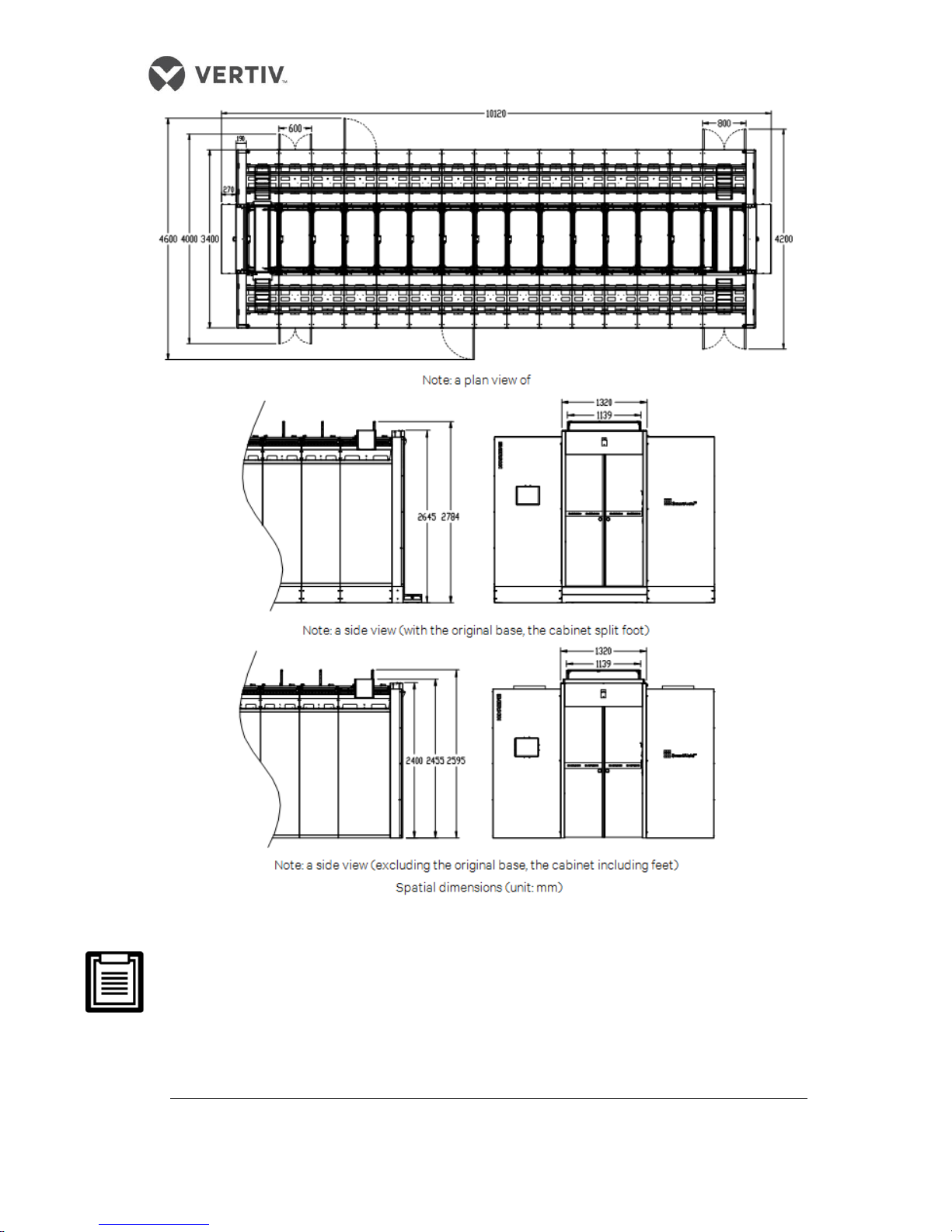
Figure 1-2 Interior Space side (Indoor)
Ensure to check the back door open space in front of the cabinet during product installation.
Always check and confirm the frame before mounting the product and the spacing between the
projecting outer enclosure level bridge.
Confirm the opening height space between the bridge, lighting, plumbing, and ceiling after the
roof opens prior to installation.
The rear cabinet door and the door from the wall end of the channel reservation must have an
appropriate distance between them to ensure easy access to equipment shelves for the
maintenance personnel.
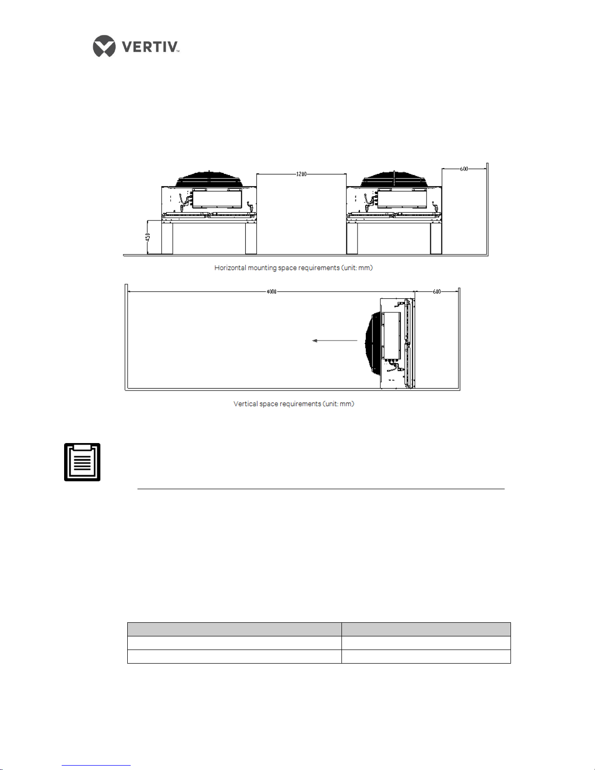
Outdoor space
Maintain sufficient space for servicing and repairs around the condenser installation position.
The detailed space requirements are depicted in Figure 1-3.
Figure 1-3 Outdoor Space
Barrier free condenser outlet is 4000mm.
Keep a space of 600 mm from the front and rear sides of the condenser for maintenance
and repairs.
1.4.4 Indoor unit and outdoor unit distance
If the one way equivalent length is over 30m, or if the vertical height difference between the
indoor unit and outdoor unit exceeds the values shown in Table 1-4, contact the Vertiv local
office or office of the local dealer to ascertain the need for additional components to extend
the pipeline and other measures
Table 1-4: Perpendicular to the indoor unit and outdoor unit level difference
Relative position
Drop
The outdoor unit is higher than indoor unit
Maximum: + 30m
The outdoor unit is below the indoor unit
Maximum: -8m
1.4.5 Load-bearing
A typical configuration of the SmartAisle product is as follows: weight of about 9 tons, an
area of about 32.6 sq m, and heavy user equipment is considered the bearing capacity post
the installation
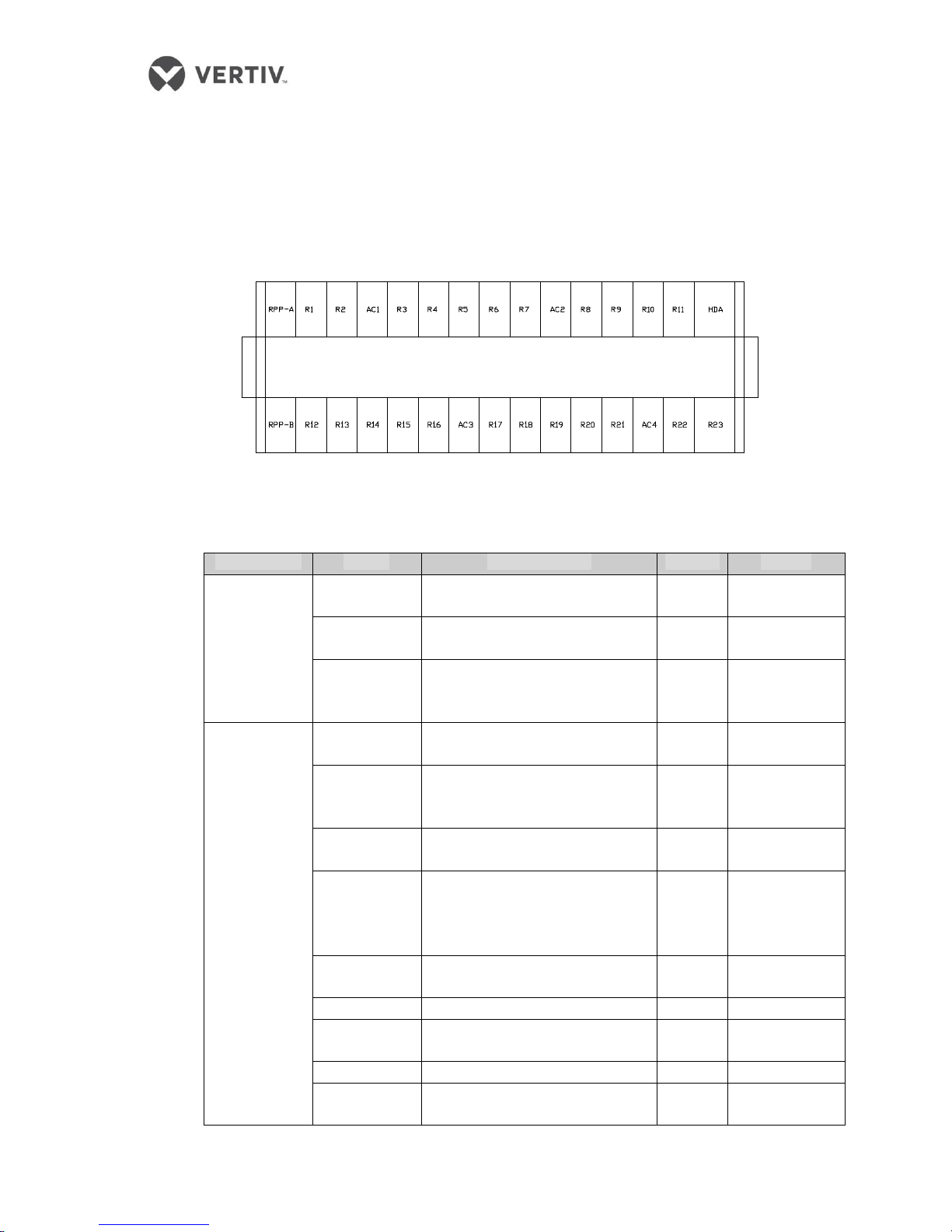
1.5 Configuration program
The layout typical configuration is shown in Figure 1-4.
Figure 1-4 Configuration Layout
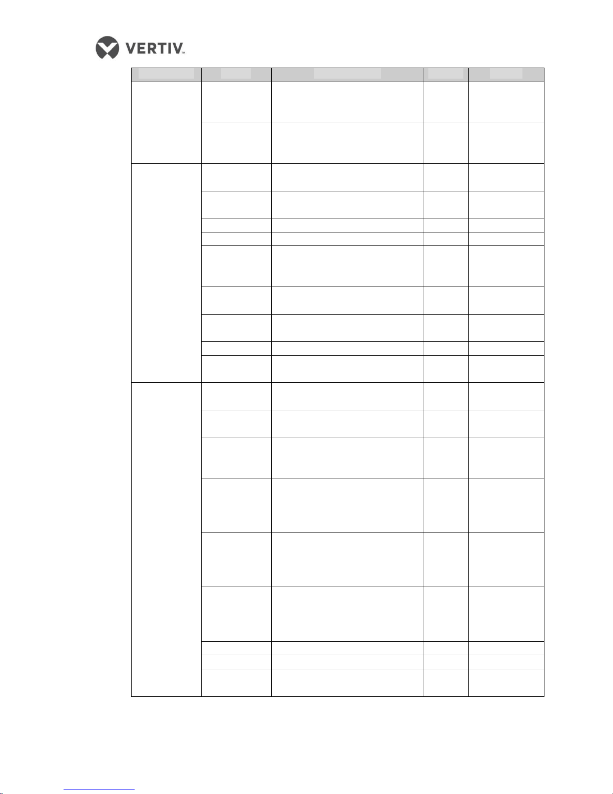
SmartAisle’s typical configuration list is described in Table 1-5.
Table 1-5 - Typical configuration list
Classification
Project
Product number
Quantity
Remark
Cabinets
600 wide
server cabinet
SR-E061120T
24 Nos
800 wide
server cabinet
SR-E081120T
1 set
800 wide
network
cabinet
SR-E081120T
1 set
Cabinet
Accessories
Cabinet side
panel
E-1120S
1 set
Vertical cable
management
panel
IRS-A-CV / E
12 sets
Windshield
side cabinet
/
2 sets
Rectangular
cable
management
unit
IRS-A-CR
16
Fixed light
load tray
IRS-A-SFL
24
1U Blind
IRS-A-B1
24 sets
2U blanking
plate
IRS-A-B2
24 sets
3U Blind
IRS-A-B3
24 sets
1U blind plate
with a brush
IRS-A-B1P
24 sets
Classification
Project
Product number
Quantity
Remark
PDU
IRS-PL30NN32
46
Cooling
Indoor air
conditioning
unit
CR035RA138SS12E10000PV000
4
Air
Conditioners
LSF42-R3 – Option 1
4
Ambient
temperature
35 °C
LSF52-R3 – Option 2
4
Ambient
temperature
40 °C
LSF76-R3 – Option 3
4
45 °C ambient
temperature
Monitoring
Card
ES025RA SIC card assembly
4 pieces
Supply and
distribution
Distribution
Cabinet
/ 2
Channel
closed
Access door
SA-D1220SEY
1 set
600 open
skylight
SA-TR0612P
13
800 open
skylight
SA-TR0812P
1 item
SPM open
skylight
SA-TP0612P
1 item
The traces
Strong crosschannel
electrical
trunking
SA-WAQ121210
1 item
Weak trough
cross-channel
SA-WAR122610
1 item
Roof slot
width 600
SA-WR06103009
28
800 Roof
wide groove
SA-WR08103009
2 pieces
Base
600 wide
base
SA-SR061125
28
800 wide
base
SA-SR081125
2 pieces
The base
access door
SA-SD121125
1 set
Positioning
the base
member
SA-SF121125
6 pieces
Administration
Kit
Administration
Kit
SA-MP
1 set
Lighting Kit
SA-LP12C
1 set
Kit control
panel
SA-DP15
1 set
Classification
Project
Product number
Quantity
Remark
Management
and other
host
RDU-M
management
host
RDU-MI
1 set
Smart Device
Expansion
Card
IRM-4COM
1
Security
ID card
reader
CHD601S
2
IP Access
Controller
CHD806D2M3
1 set
ID card
RFID01A
10
Exit Button
EP68
2
ID card
dispenser
card
CHD603B-U
1
POE Network
HD IR Dome
ES-HND200-EI
2
Standard 8
NVR
ES-RN080201-C
1 set
2T hard disk
Seagate SV35.5-2T
2
POE Smart
Switch
H3C S2626-PWR
1 set
Engineering
materials (for
field)
Industrial
Connectors
IEC 60309 32A 1P
46 sets
Single phase
cables PDU
ZA-YJV
Several
Feeding rack
PDU
Air
conditioning
phase cable
ZA-YJV
Several
Air conditioning
power cable
Single-phase
power supply
line electric
door
ZA-YJV
Several
Electric gate
power cable
Cable
Cat6
Several
Communication
with the
monitoring
system
Control Cable
AWG
Several
Communication
with the
monitoring
system
Crystal Head
RJ-45
Several
Cable splicing
Cable tie
/
Several
Tie line with
Static flooring
600x600x32mm calcium sulfate
1 set
When there is
a base
Kit configuration management is described in Table 1-6.
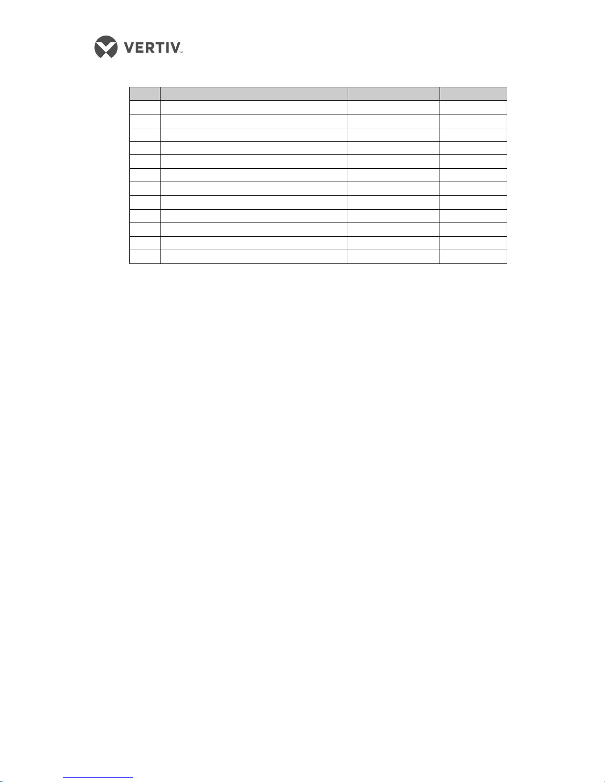
Table 1-6
No.
product name
Product number
Quantity
1
Open controller
IRS-SA-CB
1
2
RDU-A G2
IRM-HOST2
1
3
8 digital / analog output expansion card
IRM-8DOAO
1
4
Temperature and humidity sensor
IRM-S02TH
6
5
Sound and light warning light
IRM-S01AN-B
2
6
Infrared Detectors
IRM-S01IN
1
7
Flooding tape - 10 m
IRM-S01W (10m)
2
8
4 digital input sensor
IRM-S04DI
1
9
Magnetic Roof state
IRM-S01DN-B
1
10
The top button open
IRS-CF-CS
2
11
The top button open the protective cover
IRS-CF-CC
2
12
Cable set top open
IRS-SA-SW
1
The Illumination configuration kit is described in Table 1-7.
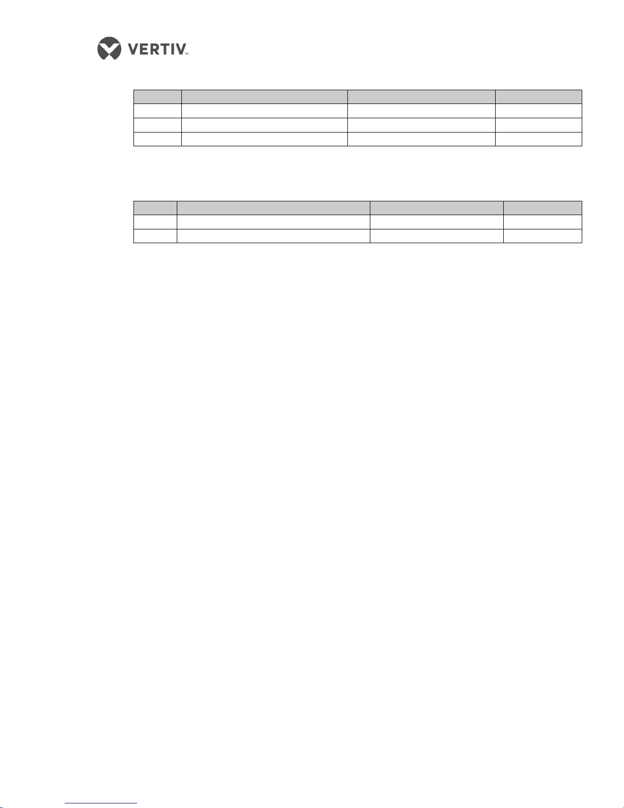
Table 1-7 Illumination configuration kit
No.
product name
Product number
Quantity
1
Lighting Controller
IRS-SA-LB
1
2
Rocker
IRS-SA-LS
1
3
Lighting cable set
IRS-SA-LW
1
The Kit control panel configuration is shown in Table 1-8.
Table 1-8
No.
product name
Product number
Quantity
1
Control panel
IRS-SA-PN
1
2
Screen control cable set
IRS-SA-PW
1

Part II
Installation

2 Installation
In this section, info about installation tools, transportation, unpacking, inspection, installation
constraints and procedures will be explained in depth to enable users to get to grips with the
process.
The SmartAisle product is on the heavier side and there is a risk of severe injury if not
handled properly.
Read all the instructions carefully prior to unpacking, shifting, or installing the unit.
Wear sturdy safety helmets, gloves, shoes, and glasses while handling the equipment due to
sharp edges, objects, and buckles.
Prior to moving the equipment such as Cabinets, air conditioning, or the distribution utility,
measure the doorways, freight height, or the freight elevators to avoid damage to the stuff or
the building.
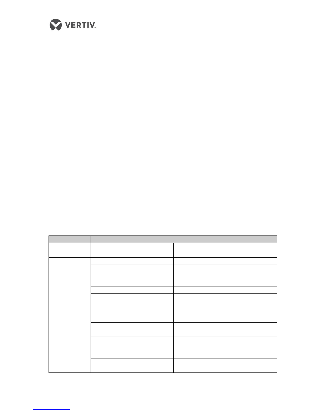
2.1 Installation Tools
Figure 2-1 shows the pictorial depiction of some of the generic installation tools.
Figure 2-1 Generic installation Tools
Table 2-1 Installation Tools
name
use
Utility Knife
Removing all kinds of packaging equipment
Phillips screwdriver
Tighten the screws when mounting the components
Small flat-blade
screwdriver
Install low-voltage terminal devices
Adjustable wrench
Adjust the various types of equipment feet
Socket wrench
Tighten the nut when installing the components
Level
Horizontal leveling control display
L Allen key
Hex bolts mounting the top plate
Line laser
Vertical projection, the level of the laser beam, verticalhorizontal adjustment device
Drill
Install the door frame on the ground
Rubber hammer
Structural parts mounting position fine adjustment tap
Pliers
Cutting the top plate rib hole modulus
ladder
Equipment installation height
2.2 Equipment handling, unpacking, inspection
Vertiv recommends rail or shipping for the product transportation. If road is the only option, choose
less bumpy roads to prevent equipment damage.
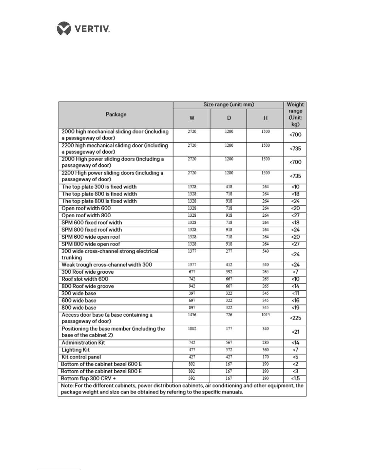
The size and weight of the package of each component is depicted in Table 2-2.
Table 2-2
The components and parts need to be shipped to the vicinity of the installation site. Owing to the
heavy weight, use machines like a pallet jack or an electric forklift.
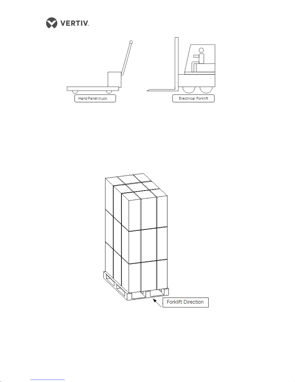
Figure 2-2 Forklift and hand pallet
While handling and unloading the equipment and cabinets, the center of gravity of the fork is to be
taken into consideration to prevent dumping or equipment damage.
Figure 2-3 Cross direction schematic view
While moving the components, the obliquity should be maintained at an angle of 80° to 100°
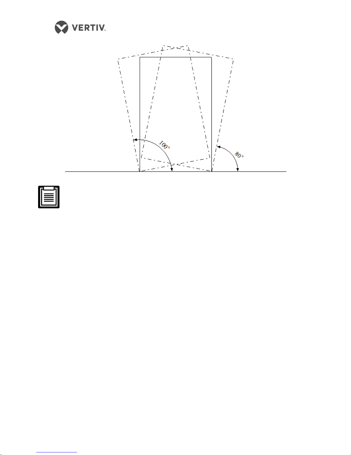
Figure 2-4 Inclination while transporting
The devices should remain upright; do not place the unit outdoors.
Use a forklift or a pallet jack with the adjustable fork arms open to the widest distance, so that
the device is placed just below the pallet. Further, ensure that the fork arm length matches the
length of the device.
Packaging material
All the material used in the packaging enclosure is re-cycleable. Either they can be retained for
future use or they can be disposed appropriately.
For China, the packaging is done in a carton box. For international locations, a wooden box is
utilized.
Following are the steps for unpacking the carton box:
The product package assembly should be done on an open, solid horizontal surface.
During disassembly, open the carton belt with a knife.
Remove the device carefully
Carefully, dismantle the film and packaging material on the product with a utility knife.
Following are the steps for unpacking the wooden box for international shipment:
The product package assembly should be done on an open, solid horizontal surface.
Using a hammer carefully and a screwdriver to dismantle the wooden packaging.
Remove the pallet
Carefully, dismantle the film and packaging material on the product with a utility knife.
Following the unpacking, confirm the parts and components by referring to the part checklist. If any
part is missing or damaged, it has to be immediately to the carrier. For concealed damage, inform
the local dealer or local Vertiv office immediately.
2.3 Installation Precautions
Following are the measures to be adhered prior to installation of the SmartAisle unit:
Close all the doors of the equipment and cabinets before using a forklift to lift the unit.
Measure and verify the installation site level prior to installation.
Confirm that charging operations are stalled and the installed power is disconnected before
installation.
For installation of indoor and outdoor air conditioning units, refer to the air conditioning
user manual
For installation of the distribution cabinet, refer to the specific user manual.
2.4 Installation Procedures
This section deals with the mechanical and electrical installation of the SmartAisle components.
Ensure that all the installation tools and accessories are in place before proceeding with the
installation process.
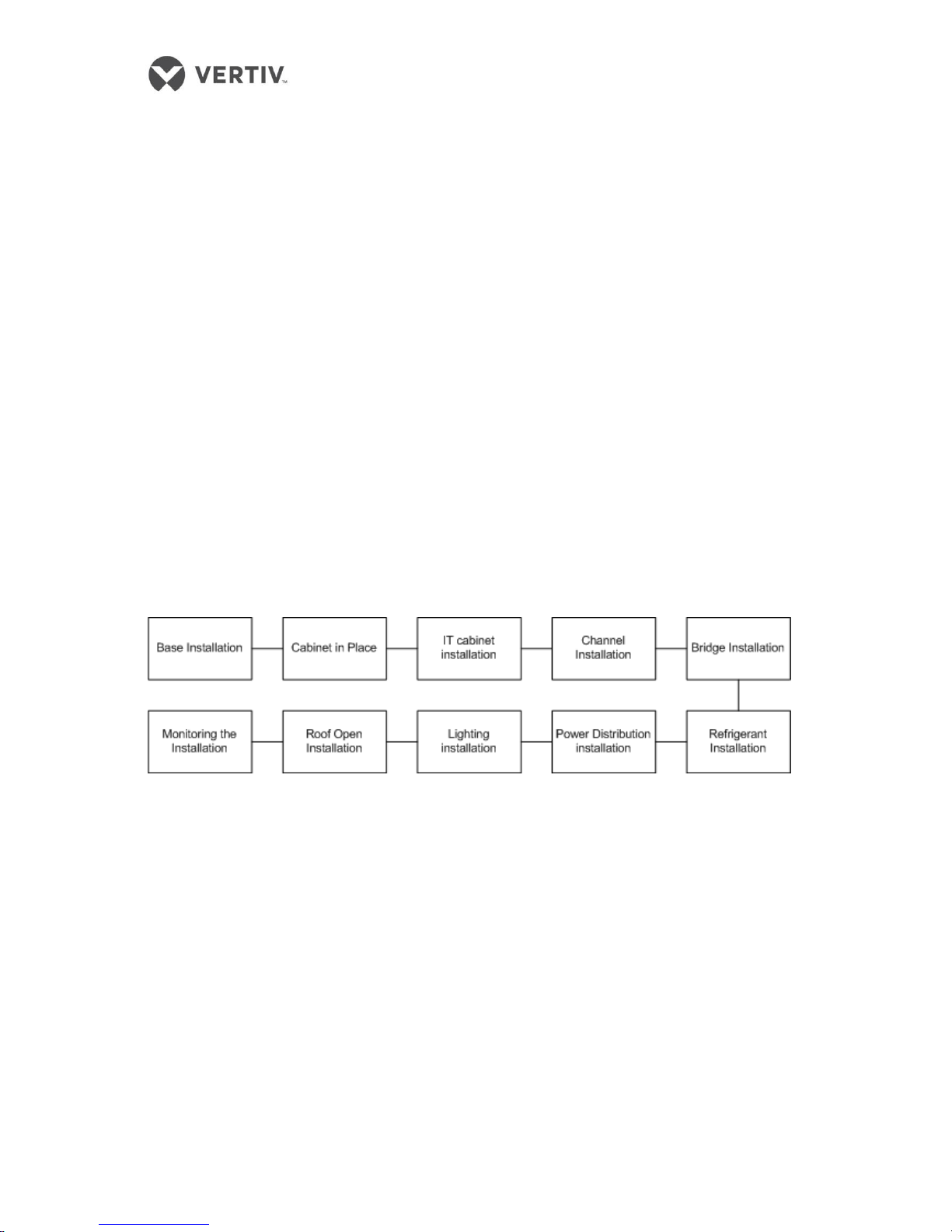
Following is the assembly flowchart for the installation process.
Figure 2-5 Assembly flowchart
S.No
Details of equipment
1
Base
2
Server Cabinet
3
Network Cabinet
4
Access door
5
Top Plate
6
A/C Column
7
Distribution Cabinet
8
Strong wire passage groove
9
Power cable trunking; copper
and fibre cable tray
11
Control panel
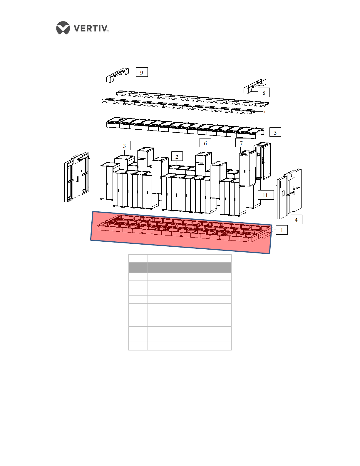
2.4.1 Installation of the base
If the base is already installed, then users can skip this section and goto section 2.4.2.
Splicing the base
Figure 2-6 shows the base assembly, cabinet base, and the limiting position assembly process.
S.No
Details of equipment
1
Base
2
Server Cabinet
3
Network Cabinet
4
Access door
5
Top Plate
6
A/C Column
7
Distribution Cabinet
8
Strong wire passage groove
9
Power cable trunking; copper
and fibre cable tray
11
Control panel
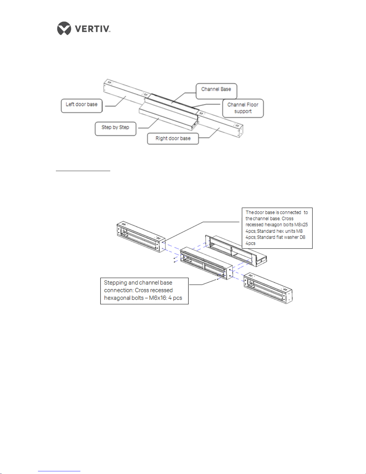
Figure 2-6 Base schema
The three parts connected and coupled in steps are the door susceptor by a channel base and the
left and right channels of the base door as shown in Figure 2-7.
Figure 2-7 Door comprising the base
Door Assembly base
Figure 2-8 shows the base assembly with a door fastener.
Figure 2-8 Door assembly base
Base is mounted inside the channel floor support.
Figure 2-9 shows the support member mounted within the floor channel.
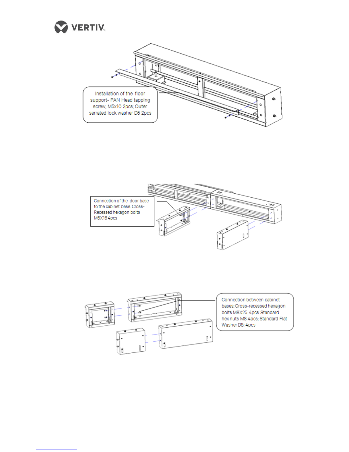
Figure 2-9 A support member mounted within the floor channel
The cabinet base is connected to the base of the door pocket and the channel base of the
cabinet is connected to the installed floor-side support member with the same base door.
Figure 2-10 Base connected to the base of the cabinet door
The connection between the base of the cabinet includes using bolts and nuts as shown in
Figure 2-11:
Figure 2-11 The connection between the base of the cabinet
While mounting channel width of the stopper member, the channel width stopper base of
the cabinet in two rows ensure a pitch of 1200mm. The base of the cabinet is connected to
two rows of the stopper member as shown in Figure 2-12. Limit the equidistant positioning
member mounted in the base assembly as much as possible on completion of the base
assembly.
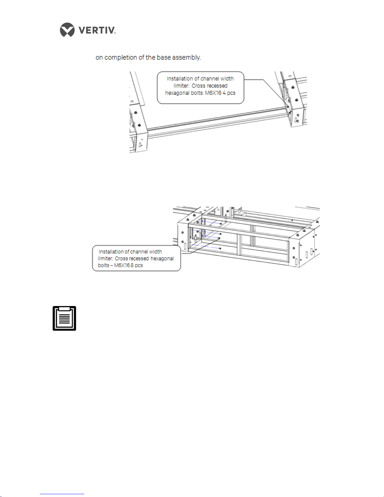
Figure 2-12 Mounting channel width of the stopper member
Installing the cabinet depth stop element is done to ensure consistency and depth of the
cabinet base is in the specified position with that of the cabinet depth.
Figure 2-13 Installation cabinet depth stop element
Stopper must be installed; if a stopper is not installed and that leads to quality issues,
the warranty is void as the customer is responsible for it.
Stopper must be installed at each distribution cabinet as well as the base of the air
conditioner to facilitate ease of installation
Fasteners are not consequential around the base.
2.4.2 Leveling the base
Figure 2-14 shows the removal of the outer base closure plate:
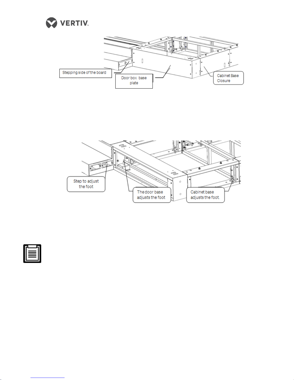
Figure 2-14 Leveling the base of the closure plate to be torn
Swing the wrench to the base leveling foot as shown in Figure 2-15:
Figure 2-15 Base tone flat feet
The nuts and bolts shall be protruding out at their maximum depth throughout the fastener
base
Levelling the base must be done using a line levelling laser and not on visual
inspection by the installation personnel
The base must be leveled to meet the cabinet and subsequent installation of a closed
system. If quality issues are caused due to uneven surface, the customer is
accountable as leveling is mandatory.
2.4.3 Fixing the base
A base is connected to ground through a fixed orifice. A predetermined ground base fixing hole and
ground connection is recommended if there are seismic requirements in the room.
2.4.4 Pre conduit arrangement
The layout diagram of the indoor air conditioning unit is prearranged within the base line and ample
length is allowed.
 Loading...