

Page 1

Liebert®
RX™ Remote Distribution Cabinet
User Manual
Page 2

The information contained in this document is subject to change
without notice and may not be suitable for all applications. While
every precaution has been taken to ensure the accuracy and
completeness of this document, Vertiv assumes no responsibility
and disclaims all liability for damages resulting from use of this
information or for any errors or omissions. Refer to other local
practices or building codes as applicable for the correct methods,
tools, and materials to be used in performing procedures not
specifically described in this document.
The products covered by this instruction manual are manufactured
and/or sold by Vertiv This document is the property of Vertiv and
contains confidential and proprietary information owned by Vertiv.
Any copying, use or disclosure of it without the written permission of
Vertiv is strictly prohibited.
Names of companies and products are trademarks or registered
trademarks of the respective companies. Any questions regarding
usage of trademark names should be directed to the original
manufacturer.
Technical Support Site
If you encounter any installation or operational issues with your product, check the pertinent
section of this manual to see if the issue can be resolved by following outlined procedures.
Visit https://www.VertivCo.com/en-us/support/ for additional assistance.
Page 3

TABLE OF CONTENTS
IMPORTANT SAFETY INSTRUCTIONS . . . . . . . . . . . . . . . . . . . . . . . . . . . . . . . . . . . . . . 1
1.0 INSTALLATION. . . . . . . . . . . . . . . . . . . . . . . . . . . . . . . . . . . . . . . . . . . . . . . . . . . . . . . . 2
1.1 Unpacking and Preliminary Inspection . . . . . . . . . . . . . . . . . . . . . . . . . . . . . . . . . . . . . . . . . . . . . . . . . . 2
1.2 Handling Considerations . . . . . . . . . . . . . . . . . . . . . . . . . . . . . . . . . . . . . . . . . . . . . . . . . . . . . . . . . . . . . . . . 2
1.3 Unit Preparation . . . . . . . . . . . . . . . . . . . . . . . . . . . . . . . . . . . . . . . . . . . . . . . . . . . . . . . . . . . . . . . . . . . . . . . . . 4
1.4 Location Considerations. . . . . . . . . . . . . . . . . . . . . . . . . . . . . . . . . . . . . . . . . . . . . . . . . . . . . . . . . . . . . . . . . 4
1.5 Configurations for Liebert RX Installation . . . . . . . . . . . . . . . . . . . . . . . . . . . . . . . . . . . . . . . . . . . . . . .4
1.5.1 Configuration 1—Single Unit . . . . . . . . . . . . . . . . . . . . . . . . . . . . . . . . . . . . . . . . . . . . . . . . . . . . . . . . . . . . . 5
1.5.2 Configuration 2—Back-to-Back . . . . . . . . . . . . . . . . . . . . . . . . . . . . . . . . . . . . . . . . . . . . . . . . . . . . . . . . . . 5
1.5.3 Configuration 3—Side-By-Side. . . . . . . . . . . . . . . . . . . . . . . . . . . . . . . . . . . . . . . . . . . . . . . . . . . . . . . . . . . 5
1.5.4 Configuration 4—Three Units . . . . . . . . . . . . . . . . . . . . . . . . . . . . . . . . . . . . . . . . . . . . . . . . . . . . . . . . . . . . 6
1.5.5 Configuration 5—Four Units . . . . . . . . . . . . . . . . . . . . . . . . . . . . . . . . . . . . . . . . . . . . . . . . . . . . . . . . . . . . . 6
1.6 Power Wiring. . . . . . . . . . . . . . . . . . . . . . . . . . . . . . . . . . . . . . . . . . . . . . . . . . . . . . . . . . . . . . . . . . . . . . . . . . . . . 8
1.6.1 Input Power Connections. . . . . . . . . . . . . . . . . . . . . . . . . . . . . . . . . . . . . . . . . . . . . . . . . . . . . . . . . . . . . . . . . 8
1.7 Output Power Connections . . . . . . . . . . . . . . . . . . . . . . . . . . . . . . . . . . . . . . . . . . . . . . . . . . . . . . . . . . . . . 14
1.8 Current Plus Monitoring—Optional. . . . . . . . . . . . . . . . . . . . . . . . . . . . . . . . . . . . . . . . . . . . . . . . . . . . . 15
1.8.1 Summary Alarm . . . . . . . . . . . . . . . . . . . . . . . . . . . . . . . . . . . . . . . . . . . . . . . . . . . . . . . . . . . . . . . . . . . . . . . . . 15
1.9 Liebert LDMF™ Monitoring—Optional . . . . . . . . . . . . . . . . . . . . . . . . . . . . . . . . . . . . . . . . . . . . . . . . . . 16
1.9.1 Replacing a CT in the CT Module. . . . . . . . . . . . . . . . . . . . . . . . . . . . . . . . . . . . . . . . . . . . . . . . . . . . . . . . 16
1.10 Liebert LDMF Communication. . . . . . . . . . . . . . . . . . . . . . . . . . . . . . . . . . . . . . . . . . . . . . . . . . . . . . . . . . 18
1.10.1 LDMF Setup Port Connection . . . . . . . . . . . . . . . . . . . . . . . . . . . . . . . . . . . . . . . . . . . . . . . . . . . . . . . . . . . 19
1.10.2 Liebert SiteScan
1.10.3 Summary Alarm . . . . . . . . . . . . . . . . . . . . . . . . . . . . . . . . . . . . . . . . . . . . . . . . . . . . . . . . . . . . . . . . . . . . . . . . . 19
®
Web Monitoring Interface . . . . . . . . . . . . . . . . . . . . . . . . . . . . . . . . . . . . . . . . . . . . 19
2.0 EQUIPMENT INSPECTION AND STARTUP . . . . . . . . . . . . . . . . . . . . . . . . . . . 20
2.1 Internal Inspection . . . . . . . . . . . . . . . . . . . . . . . . . . . . . . . . . . . . . . . . . . . . . . . . . . . . . . . . . . . . . . . . . . . . . .20
2.2 Startup. . . . . . . . . . . . . . . . . . . . . . . . . . . . . . . . . . . . . . . . . . . . . . . . . . . . . . . . . . . . . . . . . . . . . . . . . . . . . . . . . .20
3.0 INSPECTION AND STARTUP CHECKLIST. . . . . . . . . . . . . . . . . . . . . . . . . . . . . 21
3.1 Inspection. . . . . . . . . . . . . . . . . . . . . . . . . . . . . . . . . . . . . . . . . . . . . . . . . . . . . . . . . . . . . . . . . . . . . . . . . . . . . . . 21
3.2 Startup. . . . . . . . . . . . . . . . . . . . . . . . . . . . . . . . . . . . . . . . . . . . . . . . . . . . . . . . . . . . . . . . . . . . . . . . . . . . . . . . . .22
3.3 Monitoring System Check Out. . . . . . . . . . . . . . . . . . . . . . . . . . . . . . . . . . . . . . . . . . . . . . . . . . . . . . . . . . 22
4.0 OPERATING INSTRUCTIONS . . . . . . . . . . . . . . . . . . . . . . . . . . . . . . . . . . . . . . . . .23
4.1 Startup Procedures . . . . . . . . . . . . . . . . . . . . . . . . . . . . . . . . . . . . . . . . . . . . . . . . . . . . . . . . . . . . . . . . . . . . .23
4.2 Normal System Shutdown . . . . . . . . . . . . . . . . . . . . . . . . . . . . . . . . . . . . . . . . . . . . . . . . . . . . . . . . . . . . . .23
4.3 Normal System Turn On . . . . . . . . . . . . . . . . . . . . . . . . . . . . . . . . . . . . . . . . . . . . . . . . . . . . . . . . . . . . . . . .23
4.4 Current Plus Monitoring—Optional. . . . . . . . . . . . . . . . . . . . . . . . . . . . . . . . . . . . . . . . . . . . . . . . . . . . .23
4.5 Liebert LDMF™—Optional . . . . . . . . . . . . . . . . . . . . . . . . . . . . . . . . . . . . . . . . . . . . . . . . . . . . . . . . . . . . . .25
5.0 MAINTENANCE . . . . . . . . . . . . . . . . . . . . . . . . . . . . . . . . . . . . . . . . . . . . . . . . . . . . . .26
5.1 Repair . . . . . . . . . . . . . . . . . . . . . . . . . . . . . . . . . . . . . . . . . . . . . . . . . . . . . . . . . . . . . . . . . . . . . . . . . . . . . . . . . . .26
5.2 Inspection & Cleaning . . . . . . . . . . . . . . . . . . . . . . . . . . . . . . . . . . . . . . . . . . . . . . . . . . . . . . . . . . . . . . . . . .26
5.2.1 Inspection Schedule. . . . . . . . . . . . . . . . . . . . . . . . . . . . . . . . . . . . . . . . . . . . . . . . . . . . . . . . . . . . . . . . . . . . .26
Vertiv | Liebert® RX™ Remote Distribution Cabinet User Manual | i
Page 4

FIGURES
Figure 1 Typical cabinet and floor planning dimension data . . . . . . . . . . . . . . . . . . . . . . . . . . . . . . . . . . 3
Figure 2 Configuration 2 and Configuration 3—Two Liebert RX units . . . . . . . . . . . . . . . . . . . . . . . . . 6
Figure 3 Configuration 4—Three units and Configuration 5—Four units. . . . . . . . . . . . . . . . . . . . . . 7
Figure 4 Input electrical field connection location for units with main panelboard breaker . . . 9
Figure 5 Input electrical field connection location for units without main panelboard breaker.
10
Figure 6 Electrical field connections for units with LDMF monitoring . . . . . . . . . . . . . . . . . . . . . . . . 11
Figure 7 Electrical field connection for units with Current Plus Monitoring . . . . . . . . . . . . . . . . . . 12
Figure 8 Liebert LDMF™, Liebert SiteScan® and Liebert IntelliSlot™ location and connection de-
tails13
Figure 9 Current Plus Monitoring adapter board electrical field connections . . . . . . . . . . . . . . . . 15
Figure 10 Electrical field connections for CT Module replacement CTs . . . . . . . . . . . . . . . . . . . . . . . 17
Figure 11 Electrical field connections for Liebert LDMF™ summary alarm. . . . . . . . . . . . . . . . . . . . . 18
Figure 12 Liebert LDMF local display . . . . . . . . . . . . . . . . . . . . . . . . . . . . . . . . . . . . . . . . . . . . . . . . . . . . . . . . . .25
TAB LES
Table 1 Maximum wire range recommended torque values . . . . . . . . . . . . . . . . . . . . . . . . . . . . . . . . .20
Vertiv | Liebert® RX™ Remote Distribution Cabinet User Manual | ii
Page 5
IMPORTANT SAFETY INSTRUCTIONS
SAVE THESE INSTRUCTIONS
This manual contains important instructions that should be followed during installation of the
Liebert RX. Read this manual thoroughly, paying special attention to the sections that apply to
your installation, before installing or operating the Liebert RX. Retain this manual for use by
installing personnel.
Only properly trained and qualified personnel wearing appropriate safety headgear, gloves, shoes
and glasses should be involved in installing the Liebert RX or preparing the unit for installation.
In case of fire involving electrical equipment, use only carbon dioxide fire extinguishers or those
approved for use in fighting electrical fires.
Extreme caution is required when performing installation and maintenance.
Special safety precautions are required for procedures involving handling, installation and
maintenance of the Liebert RX. Observe all safety precautions in this manual before handling or
installing the unit. Observe all precautions in this manual before as well as during performance of
all maintenance procedures.
WARNING
Risk of electric shock. May cause personal injury or death.
Verify that all incoming line voltage (power) circuits are de-energized and locked out
before installing cables or making connections in the unit.
Equipment inspection and startup should be performed only by properly trained and
qualified personnel wearing appropriate safety headgear, gloves and shoes. Lethal voltages
are present during startup procedures. Electrical safety precautions must be followed
throughout inspection and startup.
Only properly trained and qualified service personnel wearing appropriate safety headgear,
gloves, shoes and glasses should perform maintenance on the Liebert RX. All voltage
sources to the unit must be disconnected before inspecting or cleaning within the cabinet.
WARNING
Risk of electric shock. May cause personal injury or death.
Lethal voltages exist within the equipment during operation. Observe all warnings and
cautions in this manual. Failure to comply may result in serious injury or death. Obtain
qualified service for this equipment as instructed. All power wiring should be installed by
licensed electricians and must comply with the NEC and applicable codes.
WARNING
Risk of heavy unit falling or tipping over. Improper handling can cause equipment damage,
injury or death.
The unit should NOT be loosened from the shipping pallet until after all handling by forklift
or pallet jack is completed. Exercise extreme care when handling Liebert RX cabinets to
avoid equipment damage or injury to personnel.
ELECTROMAGNETIC COMPATIBILITY—The Liebert RX complies with the limits for a Class A
Digital Device, pursuant to Part 15 of FCC rules. Operation is subject to the following two
conditions:
• This device may not cause harmful interference, and
• This device must accept any interference received, including interference that may cause undesired
operation.
Vertiv | Liebert® RX™ Remote Distribution Cabinet User Manual | 1
Page 6

Operating this device in a residential area is likely to cause harmful interference that users must
correct at their own expense.
The Liebert RX complies with the requirements of EMC Directive 2004/108/EC and the
published technical standards. Continued compliance requires installation in accordance with
these instructions and use of accessories approved by Vertiv.
Vertiv | Liebert® RX™ Remote Distribution Cabinet User Manual | 2
Page 7

1.0 INSTALLATION
NOTE
Read this entire manual before installing and operating the system. Upon receipt of a Liebert RX,
the installer should perform the following steps to ensure a top-quality installation.
1.1 Unpacking and Preliminary Inspection
A top-quality installation begins on the receiving dock.
• Inspect the shipment for damage or signs of mishandling before unpacking the unit(s).
•Check Shock-Watch
• Uncrate the unit carefully. Use care to avoid puncturing the container with sharp objects that would
damage the contents.
• Remove the packing and vapor barriers and inspect the equipment for any obvious shipping damage.
™
indicator.
WARNING
Risk of heavy unit falling over. Improper handling can cause equipment damage, injury or
death.
The unit should NOT be loosened from the shipping pallet until after all handling by forklift
or pallet jack is completed. Exercise extreme care when handling Liebert RX cabinets to
avoid equipment damage or injury to personnel.
1.2 Handling Considerations
The Liebert RX is bolted to a wooden pallet to allow handling by a forklift, pallet jack or similar
equipment.
Check size and weight—Refer to the cabinet drawings furnished with the unit for size and
weight information. Typical cabinet dimensions and weights are shown in Figure 1.
Plan the route—The route that the unit will follow to its installation area should be planned to
ensure that all passages are large enough to accommodate the unit and that the floors are strong
enough to support the weight. Check all doorways, hallways elevators, ramps and other portions
of the route to determine if there are any obstructions and to ensure each is large enough and
strong enough to allow easy passage.
Move with care—The Liebert RX should be moved to the installation area on the wooden pallet
using forklift or pallet jack.
If any damage is observed—Immediately file a damage claim with the shipping agency and
forward a copy to:
Vertiv
1050 Dearborn Drive
P.O. Box 29186
Columbus, Ohio 43229 USA
Vertiv | Liebert® RX™ Remote Distribution Cabinet User Manual | 3
Page 8
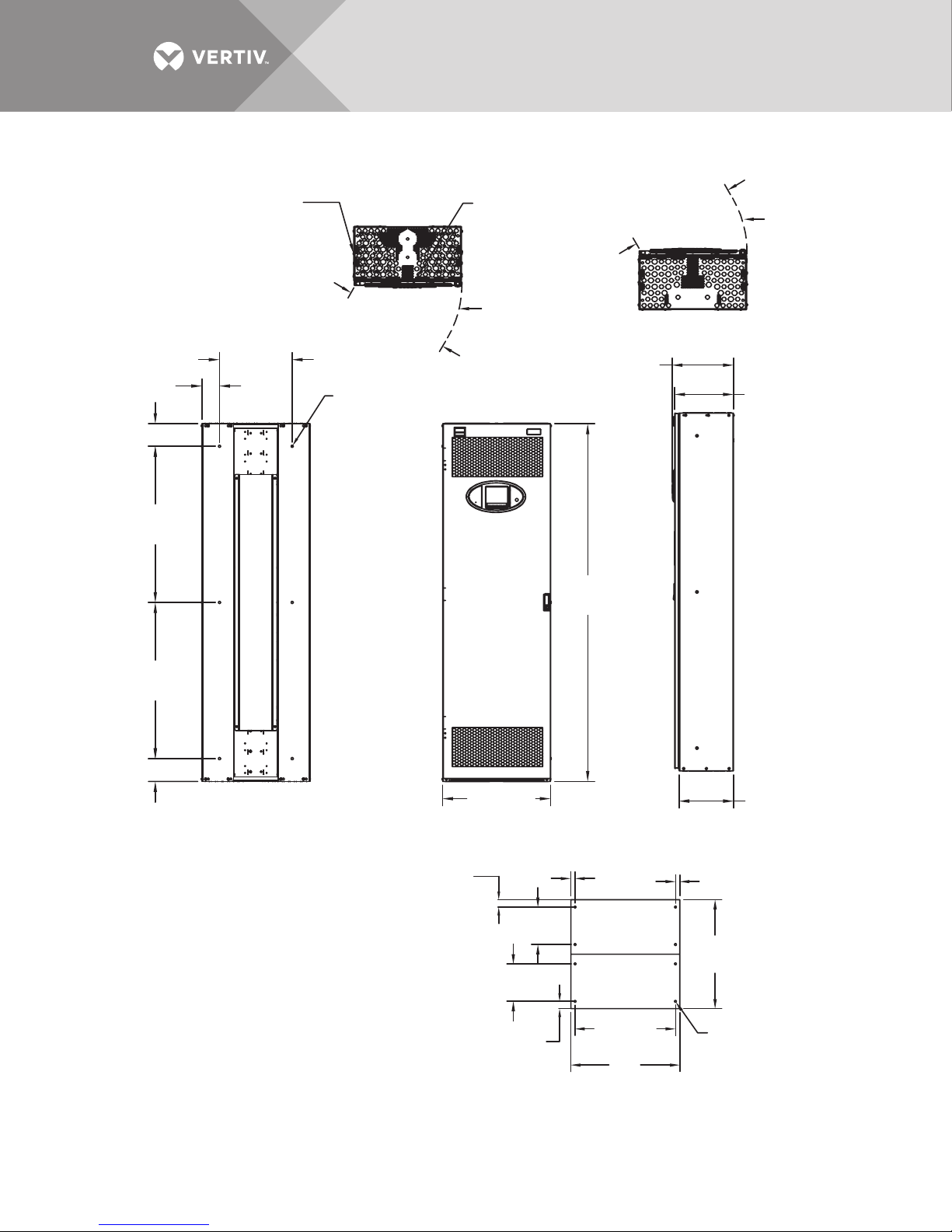
Figure 1 Typical cabinet and floor planning dimension data
3.88" (98mm)
5" (127mm)
34.37"
(873mm)
Clearance of 18"
(457mm) above unit
is recommended
for cooling airflow
16"
(406mm)
23.7 (602mm)
Top
0.44"
(11.1mm)
Clearance
Holes
Clearance of 36"
(914mm) at front
is recommended
for service access
120-degree
door
swing
13.41" (341mm)
Overall Depth
Including Bezel
78.74"
(2000mm)
23.7" (602mm)
Bottom
120-degree
door
swing
12.93"
(328mm)
34.37"
(873mm)
5" (127mm)
Rear
Mounting Holes to Attach to
Wall or Supports
NOTES:
1. Weight—225 lb. (102kg)
2. Heat Output—3412BTU/Hr (1kW)
3. Unit cannot be free-standing; it must be
attached to a wall or other support;
hardware supplied by others.
4. Units can be attached back-to-back,
side-by-side (if attached to a wall or
other support) or back-to-back with
units on one or both sides. Hardware is
included with each unit.
5. Shown with optional monitoring display.
6. See Drawing RX11001 for conduit plate details.
1.63"
(41.3mm)
23.75"
(603mm)
Front Right Side
8.25"
(210mm)
8.25"
(210mm)
1.63"
(41.3mm)
0.95"
(24mm)
22.09"
(561mm)
24"
(610mm)
0.95" (24mm)
24"
(610mm)
Ø 0.44"
(11.1mm)
Clearance
Holes
Floor Mounting
11.88" (302mm)
RX11000
Rev. 4
Vertiv | Liebert® RX™ Remote Distribution Cabinet User Manual | 4
Page 9
1.3 Unit Preparation
The Liebert RX may be easily removed from the shipping pallet and installed by customer
personnel. A typical procedure is as follows:
• Set the shipping pallet in a level area where there is enough room lift the Liebert RX off the pallet onto the
raised floor.
• Remove front door.
• Unbolt the unit from the shipping pallet. There is a bolt in each of the four bottom corners.
• Use a lifting device or an appropriate number of personnel to lift the unit off the pallet and place it on the
floor.
WARNING
Risk of heavy unit falling or tipping over. Can cause property damage, personal injury or
death.
A single Liebert RX is not designed to be a free-standing unit and may present a tipping
hazard. The Liebert RX must be properly supported and braced until it is securely attached
to a supporting structure.
NOTE
Before maneuvering the unit into its final position, read and follow all advisories in 1.4 - Location
Considerations
1.4 Location Considerations
The Liebert RX should be installed in the data center and close to the load(s) it is supplying.
Equipment location should employ the shortest output distribution cable runs consistent with
logical equipment arrangement and allowances for additional equipment.
The Liebert RX should be installed in an environment with an ambient temperature range of 32°F
to 104°F (0°C to 40°C) with a relative humidity of 0% to 95% (non-condensing).
Required clearance above the unit for cooling air flow is 18" (460 mm); clearance below for cables
is 12" (305mm) minimum. Bottom clearance is required for exit of cables/conduits and for cooling
airflow. This clearance is automatically provided by a raised floor with a minimum height of 12"
(305mm).
Recommended minimum service clearances are shown in 1.5 - Configurations for Liebert RX
Installation and Figures 2 and 3. The indicated clearance at the front of the unit is required for
service access by the National Electrical Code (NEC). Clearance above the unit is required for
cooling airflow (exhaust).
As with all electrical devices, the Liebert RX produces heat under normal operation. The heat
output is 3412 BTU/Hr (1 kWH). This heat output should be included when calculating the
environmental conditions of the room.
Vertiv | Liebert® RX™ Remote Distribution Cabinet User Manual | 5
Page 10
1.5 Configurations for Liebert RX Installation
The Liebert RX can be installed in any of five configurations. Installation will vary depending on
the chosen configuration.
• Configuration 1—Single unit
• Configuration 2—Two units attached back-to-back
• Configuration 3—Two units attached side-by-side
• Configuration 4—Three units: two attached back-to-back with the third attached to one side
• Configuration 5—Four units: two units attached back-to-back with one unit attached to each side
1.5.1 Configuration 1—Single Unit
This single-unit configuration is 24" (610mm) wide and 12" (305mm) deep. It must be secured to a
wall, rack or other structure. The required front service access is:
• 36" (914 mm) for units up to 150V to ground
• 42" (1067 mm) for units over 150V to ground
WARNING
Risk of heavy unit falling or tipping over. Can cause property damage, personal injury or
death.
The Liebert RX is not designed to be a free-standing unit in this configuration and may
present a tipping hazard. The Liebert RX must be properly supported until it is securely
attached to a supporting structure.
1.5.2 Configuration 2—Back-to-Back
This two-unit configuration is attached back-to-back and is 24" (610mm) wide and 24" (610mm)
deep. The two units can be can be installed in place of a floor tile. Remove one 24" x 24" (610 x
610mm) floor tile and position the Liebert RX over the opening, the unit will rest on top of the
raised floor cross members on all four sides. Refer to Figure 2.
1.5.3 Configuration 3—Side-By-Side
This two unit configuration is attached side-by-side and is 48" wide and 12" (305mm) deep. The
units must be secured to a wall, rack or other structure. Refer to Figure 2.
WARNING
Risk of heavy unit falling or tipping over. Can cause property damage, injury or death.
The Liebert RX is not designed to be a free-standing unit in this configuration and may
present a tipping hazard. The Liebert RX must be properly supported until it is securely
attached to a supporting structure.
Vertiv | Liebert® RX™ Remote Distribution Cabinet User Manual | 6
Page 11
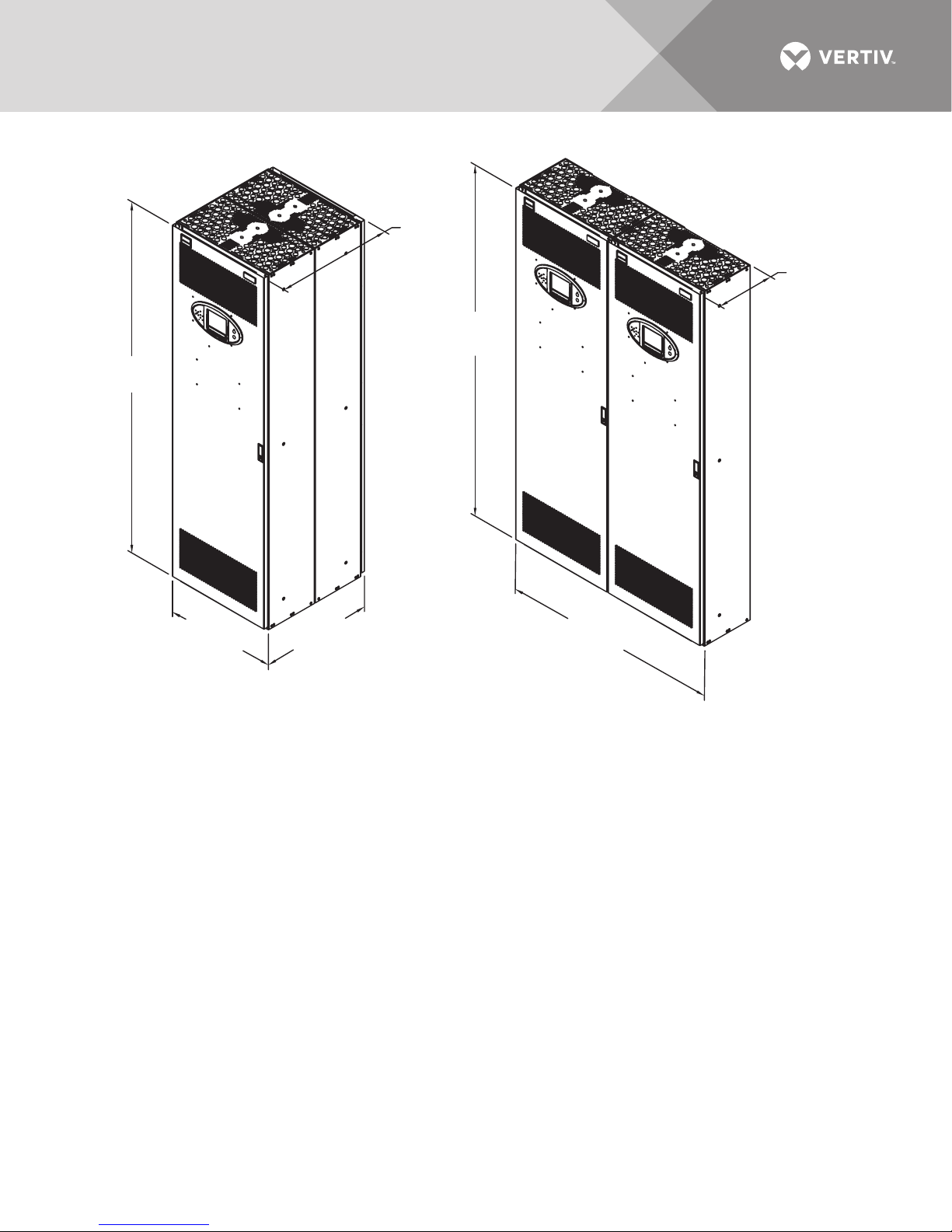
Figure 2 Configuration 2 and Configuration 3—Two Liebert RX units
25.86"
(657mm)
78.74"
(2000mm)
78.74"
(2000mm)
12.93"
(328mm)
23.75"
(603mm)
23.75"
(603mm)
47.5"
(1207mm)
CONFIGURATION 3
CONFIGURATION 2
Side-by-Side
Back-to-Back
NOTES:
1. Units are ordered and shipped separately.
Units can be attached in the field as shown.
2. Side-by-side units are not free-standing. They
must be attached to a wall or other support.
Mounting hardware supplied by others.
3. Hardware to attach units to each
other is factory-supplied.
4. Shown with optional monitoring display.
5. Configuration 2 requires front and rear
service access.
6. Configuration 3 requires front service access.
7. Service access clearance dimensions:
36" (914mm) for units up to 150V to ground
42" (1067mm) for units over 150V to ground
8. Clearance above the unit for cooling air flow: 18"
(460 mm) minimum
9. Clearance below for cables:12" (305mm)
minimum.
RX17000
Rev. 1
1.5.4 Configuration 4—Three Units
This three-unit configuration has two units attached back-to-back with a third unit attached to
the side. It is 36" wide and 24" (610mm) deep. These units are free-standing and can be set on a
raised floor. Refer to Figure 3.
1.5.5 Configuration 5—Four Units
This four-unit configuration has two units attached back-to-back with one unit attached to each
side. It is 48" wide and 24" (610mm) deep. These units are free-standing and can be set on a raised
floor. Refer to Figure 3.
Vertiv | Liebert® RX™ Remote Distribution Cabinet User Manual | 7
Page 12
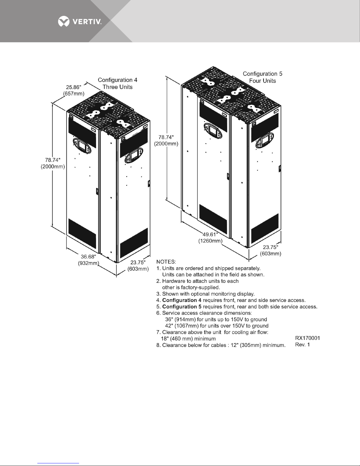
Figure 3 Configuration 4—Three units and Configuration 5—Four units
Vertiv | Liebert® RX™ Remote Distribution Cabinet User Manual | 8
Page 13
1.6 Power Wiring
Power wiring should be installed by licensed electricians. All power wiring must comply with the
NEC and applicable local codes.
1.6.1 Input Power Connections
Remove the front door. Open the accent panel, punch the top and/or bottom conduit tray to
match the number and size of the input conduit(s) and attach the input feeder.
Input power cables should be connected to the input lugs located inside the unit. (See Figures 4
through 7 and the electrical field connection drawing supplied with the unit for details.)
WARNING
Risk of electric shock. Can cause personal injury or death.
Verify that all incoming line voltage (power) circuits are de-energized and locked out
before installing cables or making connections in the unit.
Before proceeding with installation, read all instructions, verify that all the parts are
included and check the nameplate to be sure the voltage matches available utility power.
Follow all local codes.
To minimize disturbances caused by other loads in the building, the 3-phase power input to the
unit should be supplied directly from a dedicated power source.
The input feeder circuit should be sized in accordance with the NEC and any local building codes
to ensure the feeder’s ability to safely carry the system’s full load current, including losses.
Input feeder conductors should be sized for no more than 2% voltage drop. If operation at
undervoltage conditions for extended periods of time is desired, the input feeders must be
oversized.
The main input feeder must consist of 3-phase conductors, one neutral and one (safety) ground
conductor (4W + G).
Vertiv | Liebert® RX™ Remote Distribution Cabinet User Manual | 9
Page 14
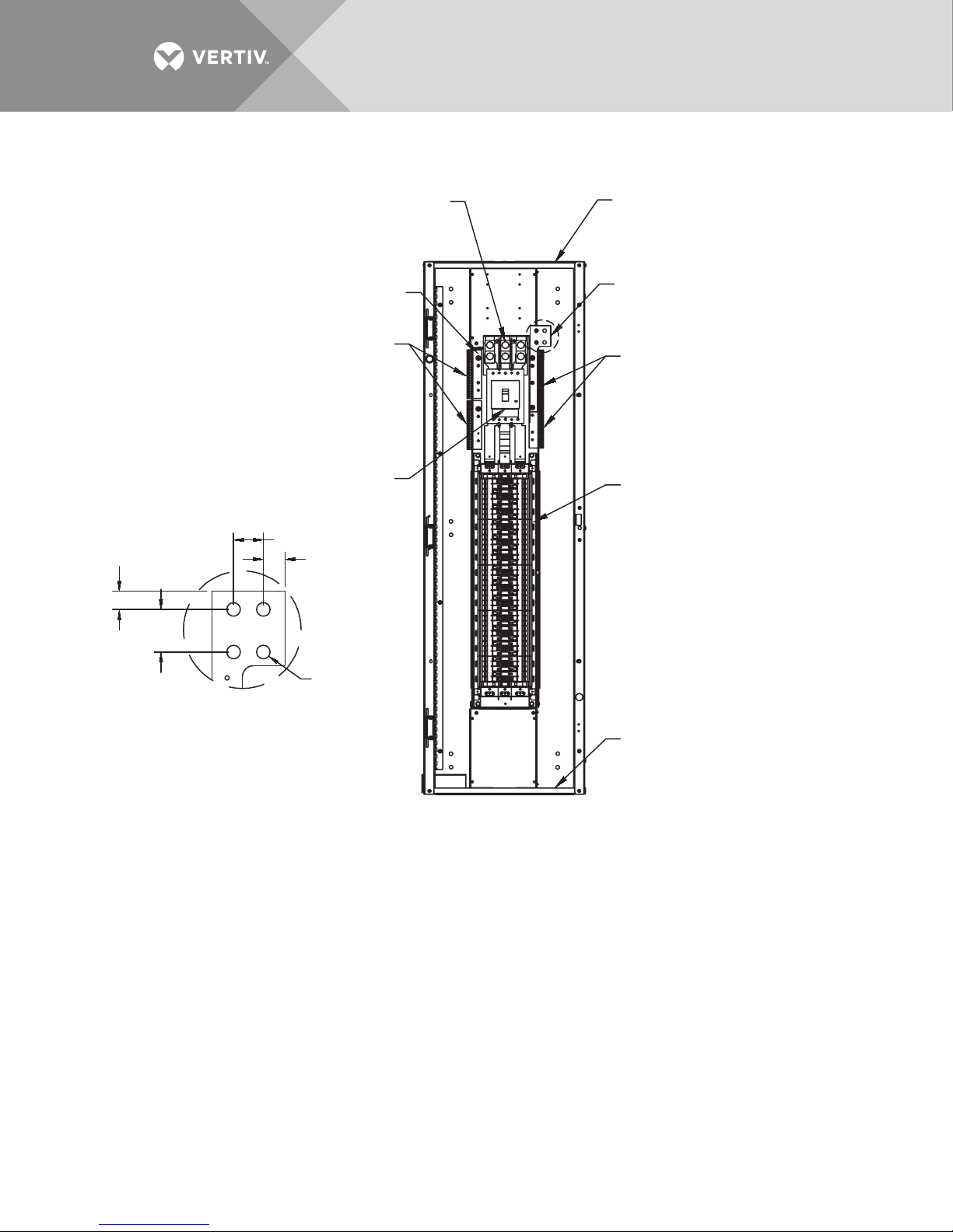
Figure 4 Input electrical field connection location for units with main panelboard breaker
0.75"
(19.1mm)
1.75"
(44mm)
Input Power Connection
Mechanical Lug for
(2) 3/0-500kCMIL
Input Ground Connection
5/16-18 x 1.5" Stud
Ground
Busbar
Main Input
Circuit Breaker
1.22" (31mm)
0.89" (23mm)
Distribution Cable Conduit
Plate; 56 knockouts, each Ø 0.875"
for 1/2" conduit and 28 knockouts,
each Ø 1.125" for 3/4" Conduit
Input Neutral Connection
See Detail A
Neutral
Busbar
84-Pole
Distribution
Panelboard
DETAIL A
Ø 0.563
(14.29mm)
4 Places
RX15002
Rev. 2
Distribution Cable
Conduit Plate
84 knockouts, each Ø 0.875"
for 1/2" conduit
Vertiv | Liebert® RX™ Remote Distribution Cabinet User Manual | 10
Page 15
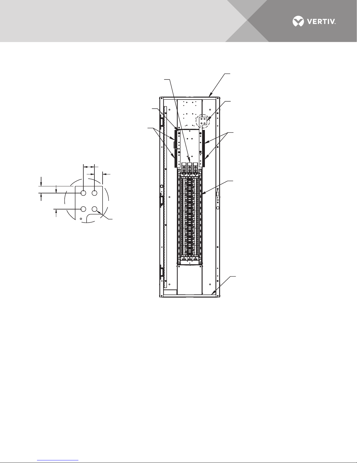
Figure 5 Input electrical field connection location for units without main panelboard breaker
0.75"
(19.1mm)
1.75"
(44mm)
Input Power Connection
Mechanical lug for
(2) 1/0-750kCMIL
Input Ground Connection
5/16-18 x 1.5" Stud
Ground
Busbar
1.22" (31mm)
0.89" (23mm)
Ø 0.563
(14.29mm)
DETAIL A
4 Places
Distribution Cable Conduit
Plate; 56 knockouts, each Ø 0.875"
for 1/2" conduit and 28 knockouts,
each Ø 1.125" for 3/4" Conduit
Input Neutral Connection
See Detail A
Neutral
Busbar
84-Pole
Distribution
Panelboard
RX15005
Rev. 2
Distribution Cable
Conduit Plate
84 knockouts, each Ø 0.875"
for 1/2" conduit
Vertiv | Liebert® RX™ Remote Distribution Cabinet User Manual | 11
Page 16
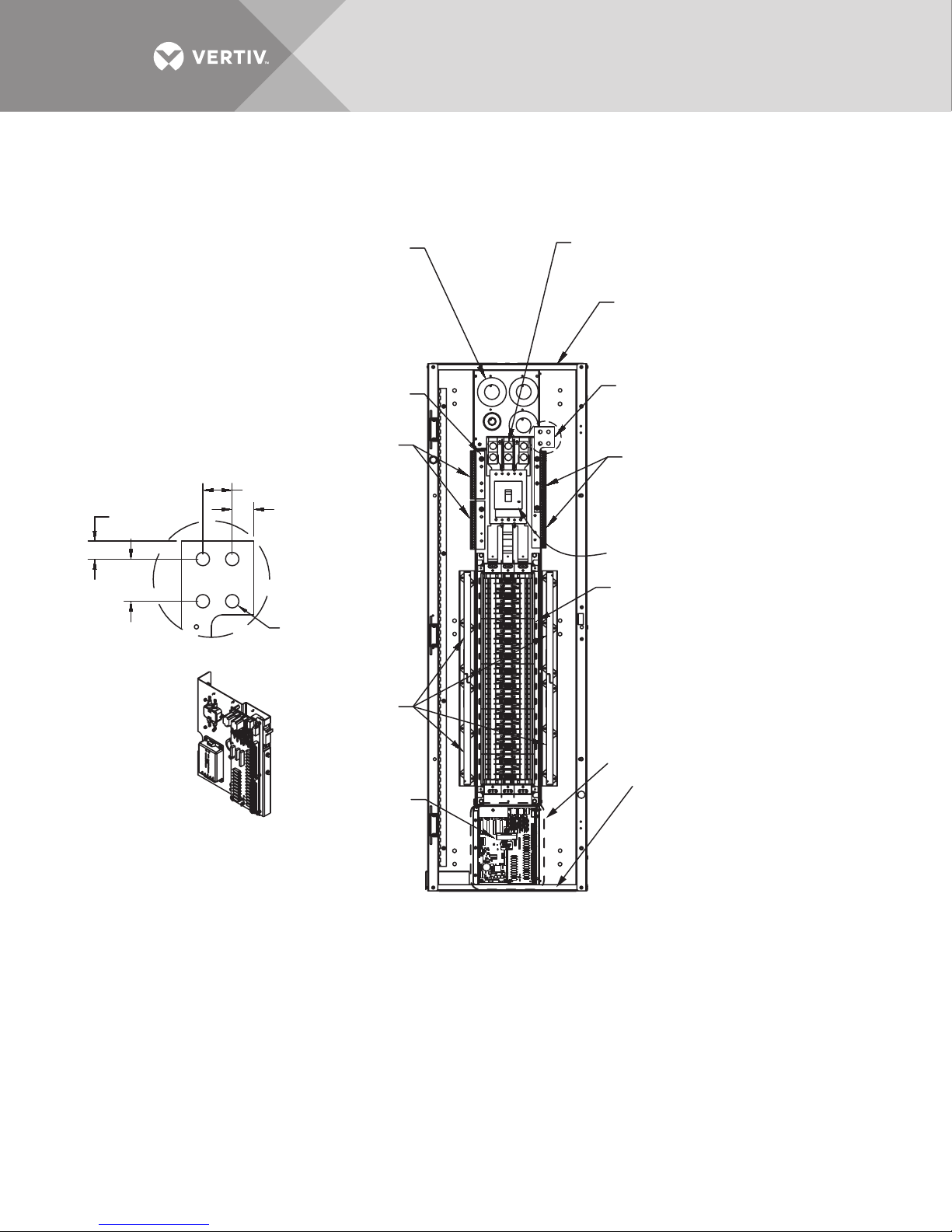
Figure 6 Electrical field connections for units with LDMF monitoring
Cut the wire ties and remove
the CT's. Run the input phase,
ground and neutral cables
through the CT's and secure
to the cable with wire ties. Install
the CT on the cable with the
white dot facing the source
for the phase connectors
and facing the load for the ground
and neutral.
Input Power Connection
Mechanical lug for
(2) 3/0-500kCMIL
Distribution Cable Conduit
Plate; 56 knockouts, each Ø 0.875"
for 1/2" conduit and 28 knockouts,
each Ø 1.125" for 3/4" Conduit
Input Ground Connection
5/16-18 x 1.5" Stud
1.22" (31mm)
0.75"
0.89" (23mm)
(19.1mm)
1.75"
(44mm)
Ø 0.563
(14.29mm)
DETAIL A
4 Places
LDMF Current
Sensors
DETAIL B
(See drawings LDM13004 and
LDM13008 for connection details.)
Ground
Busbar
LDMF
Input Neutral Connection
See Detail A
Neutral
Busbar
Main Input
Circuit Breaker
84-Pole
Distribution
Panelboard
See Detail B
Distribution Cable
Conduit Plate
84 knockouts, each Ø 0.875"
for 1/2" conduit
RX15000
Rev. 3
Vertiv | Liebert® RX™ Remote Distribution Cabinet User Manual | 12
Page 17
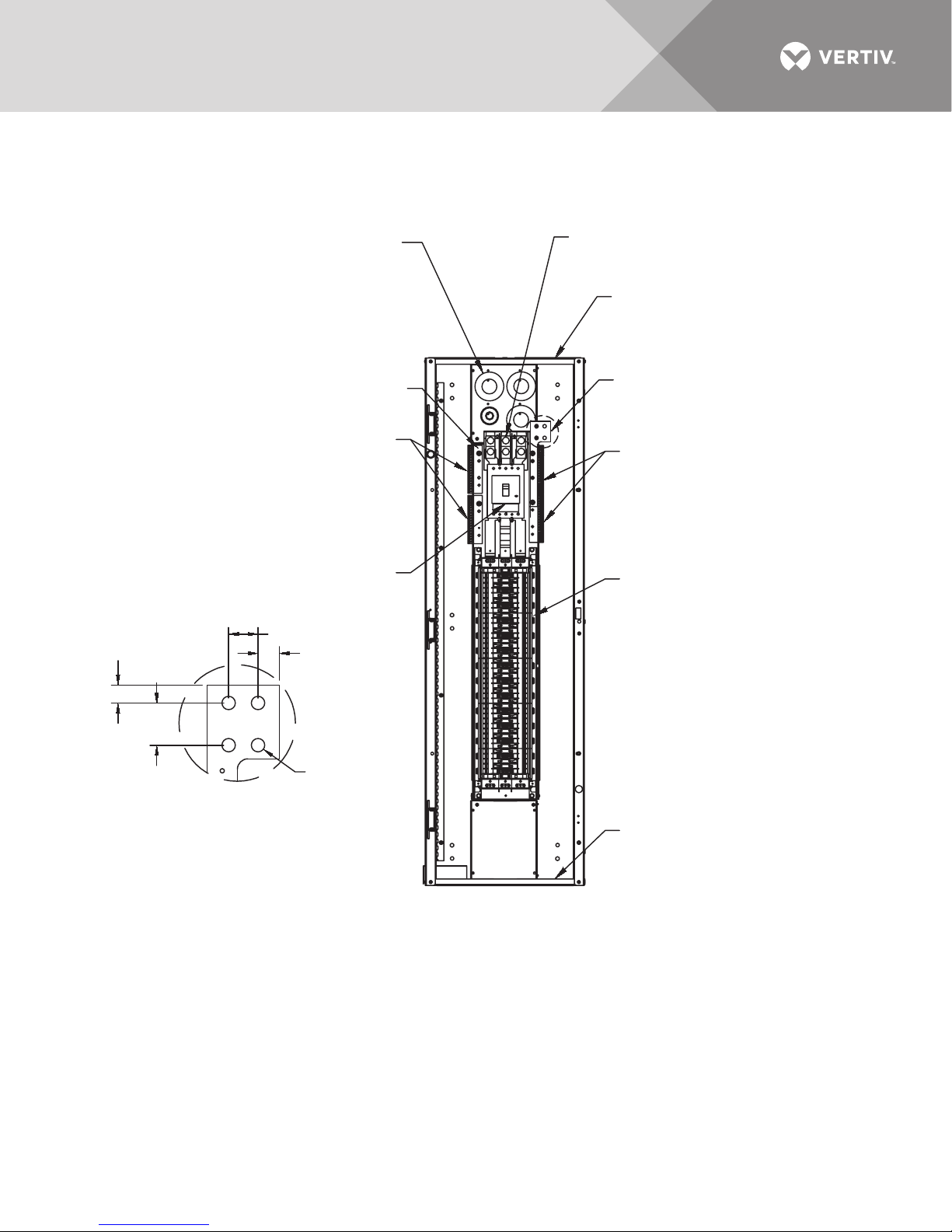
Figure 7 Electrical field connection for units with Current Plus Monitoring
Cut the wire ties and remove
the CT's. Run the input phase,
ground and neutral cables
through the CT's and secure
to the cable with wire ties. Install
the CT on the cable with the
white dot facing the source
for the phase connectors
and facing the load for the ground
and neutral.
Ground
Busbar
Neutral
Busbar
Input Ground Connection
5/16-18 x 1.5" Stud
Input Neutral Connection
See Detail A
Input Power Connection
Mechanical lug for
(2) 3/0-500kCMIL
Distribution Cable Conduit
Plate; 56 knockouts, each Ø 0.875"
for 1/2" conduit and 28 knockouts,
each Ø 1.125" for 3/4" Conduit
84-Pole
Distribution
Panelboard
Distribution Cable
Conduit Plate
84 knockouts, each Ø 0.875"
for 1/2" conduit
Main Input
Circuit Breaker
DETAIL A
RX15001
Rev. 2
Ø 0.563
(14.29mm)
4 Places
0.75"
(19.1mm)
1.75"
(44mm)
0.89" (23mm)
1.22" (31mm)
Vertiv | Liebert® RX™ Remote Distribution Cabinet User Manual | 13
Page 18
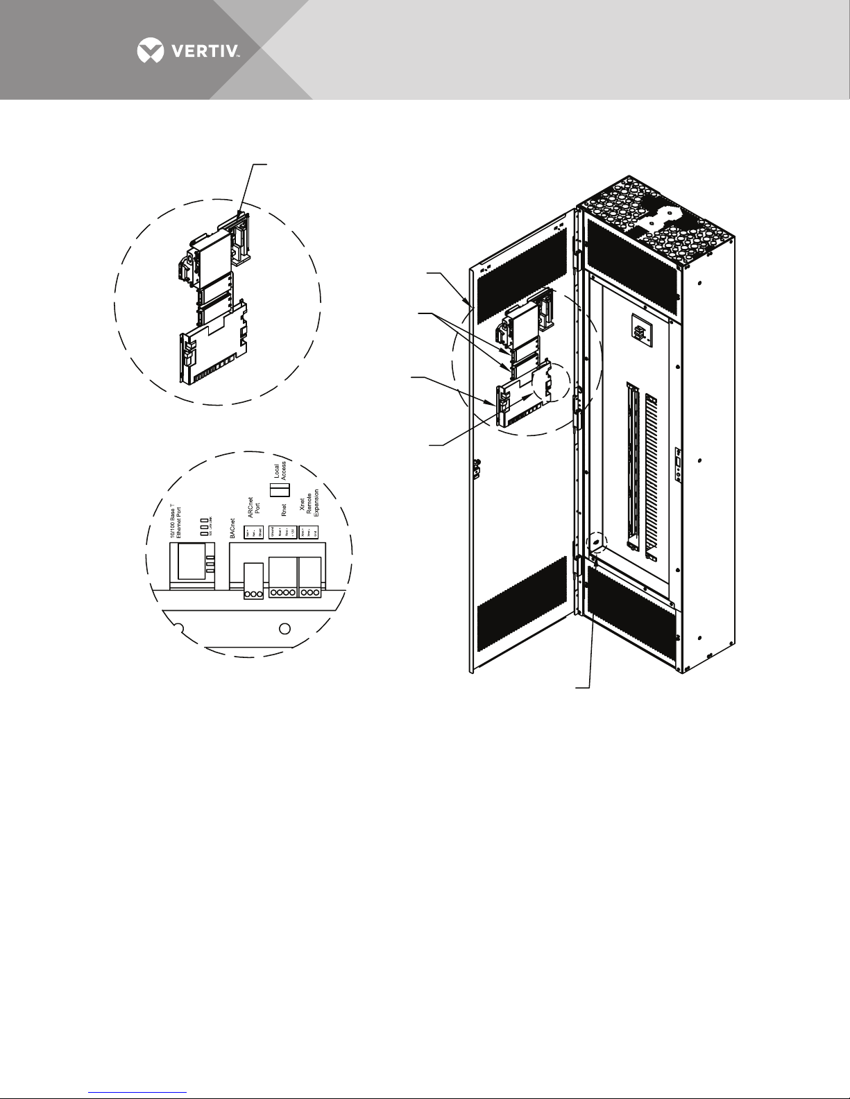
Figure 8 Liebert LDMF™, Liebert SiteScan® and Liebert IntelliSlot™ location and connection details
RX15006
Rev. 1
Liebert
IntelliSlot
Bays
Liebert LDMF
Liebert SiteScan
Interface (optional)
Adapter Board Connection
Details. See Drawing LDM13008
for Liebert LDMF. For Current
Plus, see drawing LDM13011
Detail A
See Detail A
See Detail B
DB-9 Connector-Liebert
LDMF/Current Plus
Setup Port Connection
Detail B
Vertiv | Liebert® RX™ Remote Distribution Cabinet User Manual | 14
Page 19

1.7 Output Power Connections
An output panelboard with ground and neutral provisions is provided inside the unit for
connecting load(s) as required. (See Figures 4, 5 and 6).
Flexible output distribution cables are used in data processing areas under a raised floor. Cable
lengths and layout should be well planned:
• Cable routes should follow aisles between equipment. This will facilitate access to cables for installation,
routine inspection and future changes.
• Determine the required cable length by measuring the distance to the load equipment following rightangle paths, rather than diagonally or directly. Always measure to the extreme far side of the equipment
with respect to the unit to insure adequate cable length.
• Prevent restriction of airflow under the raised floor by running the flexible conduits flat on the sub-floor,
in parallel paths.
• Initial system output loading should be between 50% and 75% of rated capacity. This allows the addition
of future loads without immediately investing in another Liebert RX.
• Balancing of loads is good design practice on any 3-phase system.
WARNING
Risk of electric shock. Can cause personal injury or death.
Verify that all incoming line voltage (power) circuits are de-energized and locked out
before installing cables or making connections in the unit.
Before proceeding with installation, read all instructions, verify that all the parts are
included and check the nameplate to be sure the voltage matches available utility power.
Follow all local codes.
• All output cables and connections must comply with the NEC and all other applicable codes.
• All output cables without receptacles that are hard-wired to the load equipment must be equipped with a
padlock-off accessory for the output circuit breaker. The padlock-off accessory is used to lock out and
tag the circuit breaker while service is performed on the hard-wired load equipment in accordance with
OSHA safety rules.
Vertiv | Liebert® RX™ Remote Distribution Cabinet User Manual | 15
Page 20
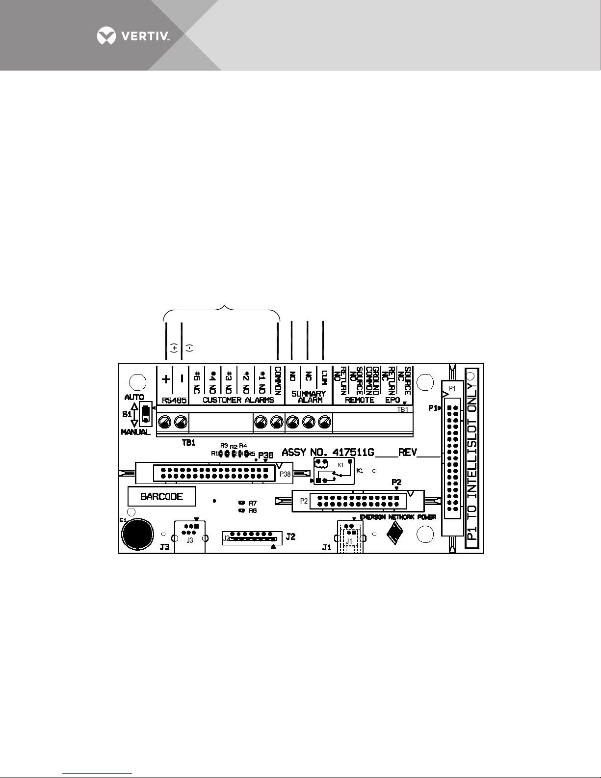
1.8 Current Plus Monitoring—Optional
NOTES:
1. The summary alarm contacts are rated
for 0 to 30VAC or VDC, 0.5A, 10 watts, maximum.
2. For Liebert SiteScan connection, use #22AWG
shielded cable; maximum distance: 1000ft (300m).
To Liebert
SiteScan
System
Summary
Alarm
LDM13011
Rev. 0
ShieldNCNO
COM
If Current Plus Monitoring (CPM) is supplied, remote communications and summary alarm
connections are available.
A Liebert IntelliSlot™ card provides connection to a Building Management System (BMS) or
Liebert SiteScan® monitoring interface. The following cards are available:
• IS-WEBS card for SNMP/Web output to Ethernet LAN
• IS-485S card for Modbus 485 output using a two-wire connection
• IS-IPBMS card for Modbus IP output using an RJ-45 connection
• IS-UNITY-DP card for HTTP/HTTPS, Vertiv Protocol, e-mail, SMS, SNMP v1/v2c/v3, BACnet IP/MSTP
and Modbus TCP/RTU output using a serial RS-485 two-wire connection
Check Liebert IntelliSlot slots on the back of the door to determine which card is supplied, more
than one card might be supplied. See Figures 8 and 9 for location and connection details.
Figure 9 Current Plus Monitoring adapter board electrical field connections
1.8.1 Summary Alarm
Current Plus Monitoring provides a Form C (one NO and one NC) summary alarm contact for
remote alarm status. The summary alarm contacts change state upon occurrence of any alarm
including warnings and reset when the alarm is cleared. The summary alarm connection is on the
Adapter Board (see Figure 8, Detail A, and Figure 11) marked Summary Alarm (NC) (NO) and
(COMM). The contacts are rated at 24VAC at 1A.
Vertiv | Liebert® RX™ Remote Distribution Cabinet User Manual | 16
Page 21
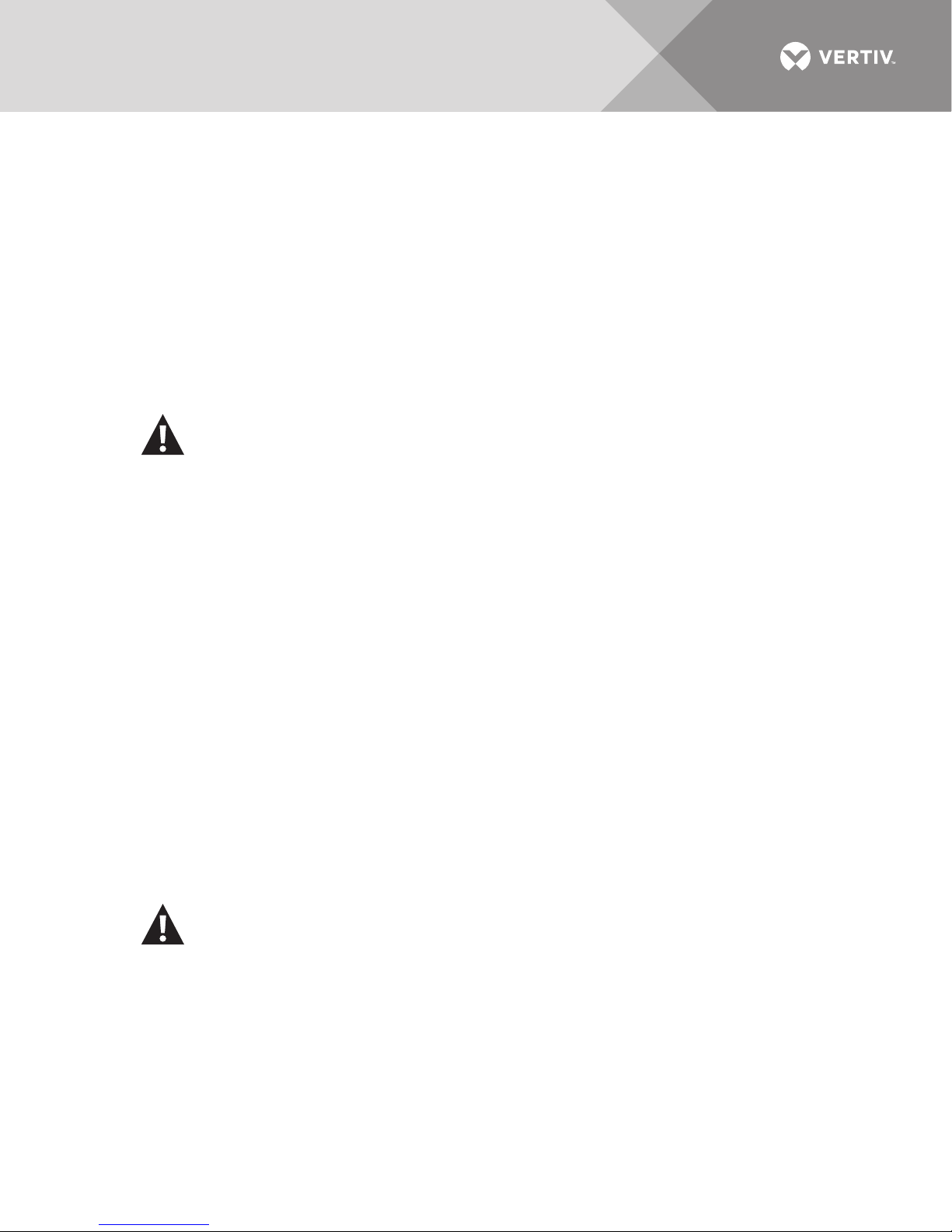
1.9 Liebert LDMF™ Monitoring—Optional
If Liebert LDMF monitoring is supplied, remote communications and summary alarm connections
are available.
A Liebert IntelliSlot® card provides connection to a Building Management System (BMS) or to
Liebert SiteScan® monitoring interface. The following cards are available:
• IS-WEBS card for SNMP/Web output to Ethernet LAN
• (IS-485S card for Modbus 485 output using a two-wire connection
• IS-IPBMS card for Modbus IP output using an RJ-45 connection
• IS-UNITY-DP card for HTTP/HTTPS, Vertiv Protocol, e-mail, SMS, SNMP v1/v2c/v3, BACnet IP/MSTP
and Modbus TCP/RTU output using a serial RS-485 two-wire connection
Check Liebert IntelliSlot bays on the back of the door to determine which card is supplied; more
than one card might be supplied. See Figures 7, 8 and 11 for location and connection details.
WARNING
Risk of electric shock. Can cause personal injury or death.
Verify that the panelboard voltage (power) circuit is de-energized and locked out before
installing branch breakers and cables or making connections in the unit.
Before proceeding with installation, read all instructions, verify that all the parts are
included and check the nameplate to be sure the voltage matches available utility power.
Follow all local codes.
1.9.1 Replacing a CT in the CT Module
In the unlikely event a CT in the CT Module should fail, up to six replacement CTs may be installed
using a split core CT kit, available separately from your local Vertiv representative.
1. Verify that the branch breaker is Off and power is de-energized.
2. Route wiring from the transformer through the panel to the control board.
3. Connect the CT connector to the proper panel location using the first available connection. See Figure 10
for details:
a. For panelboard A use P2 (A1), P3 (A2), P4 (A3).
b. For panelboard B use P5 (B1), P6 (B2), P7 (B3).
Ensure all routed wiring is properly secured to the panel with tie wraps.
4. The top piece of the current transformer (CT) is removable by pulling away from the center of the
transformer (Figure 10, Item 2).
5. Place the main body of the current transformer around the cable, making sure the CT is installed in the
direction shown in Figure 10, Item 2.
6. Replace the top piece of the CT to complete securing the CT around the cable (Figure 10, Item 3), then
use the enclosed tie wraps to secure the CT to the cable.
WARNING
Risk of electric shock. Can cause personal injury or death.
Lethal voltages are present during startup procedures. Electrical safety precautions must
be followed throughout inspection and startup. Do not open circuit the secondary windings
of current transformers. Failure to follow these instructions may result in serious injury or
death.
Vertiv | Liebert® RX™ Remote Distribution Cabinet User Manual | 17
Page 22
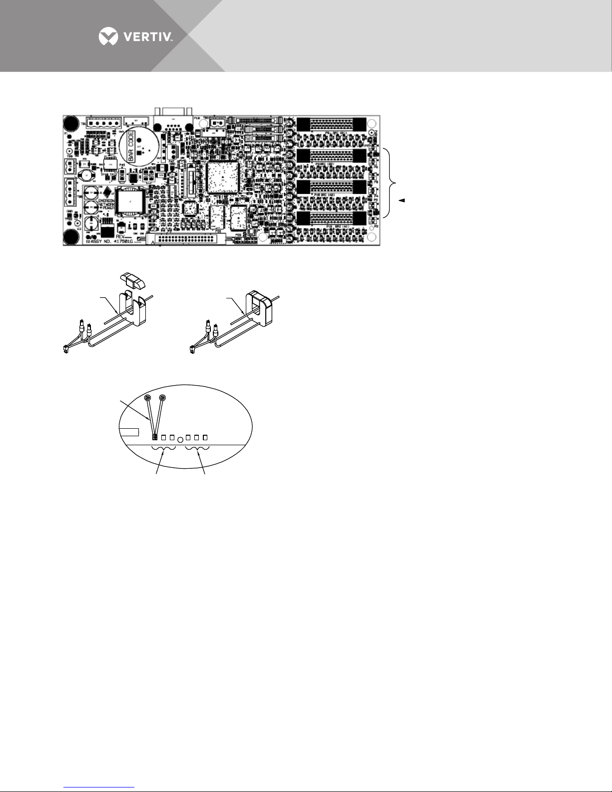
Figure 10 Electrical field connections for CT Module replacement CTs
CONNECTION LOCATION FOR CT MODULE
6 REPLACEMENT CTs.
INDICATES PIN 1.
CONNECT CT WHITE WIRE TO PIN 1
CONNECT CT BLACK WIRE TO PIN 2
LOAD
PAN E L BOAR D B
LDM13004
Rev. 0
NOTES:
1. REMOVE CT FROM THE BOX. ROUTE WIRING FROM
THE TRANSFORMER THROUGH THE PANEL TO THE
LDM CONTROL BOARD.
2. CONNECT THE CT CONNECTOR TO THE PROPER PANEL
LOCATION USING THE FIRST AVAILABLE CONNECTION:
A. FOR PANELBOARD A USE P2(A1), P3(A2), P4(A3)
B. FOR PANELBOARD B USE P5(B1), P6(B2), P7(B3)
ENSURE ALL ROUTED WIRING IS PROPERLY SECURED
TO THE PANEL WITH TIE WRAPS.
3. THE TOP PIECE OF THE CURRENT TRANSFORMER (CT)
IS REMOVABLE BY PULLING AWAY FROM THE CENTER
OF THE TRANSFORMER (ITEM 2).
4. PLACE THE MAIN BODY OF THE CURRENT
TRANSFORMER AROUND THE CABLE, MAKING SURE
THE CT IS INSTALLED IN THE DIRECTION SHOWN
(SEE ITEM 2).
5. REPLACE THE TOP PIECE OF THE CT TO COMPLETE
SECURING THE CT AROUND THE CABLE (SEE ITEM 3).
USE THE ENCLOSED TIE WRAPS TO SECURE THE CT
TO THE CABLE.
* WARNING: DO NOT OPEN CIRCUIT THE SECONDARY
WINDINGS OF CURRENT TRANSFORMERS. FAILURE
TO FOLLOW THESE INSTRUCTIONS MAY RESULT IN
SERIOUS INJURY OR DEATH.
ITEM 3ITEM 2
DETAIL A
PANELBOARD A
REPLACEMENT
CT (6 PL. TYP.)
BRANCH
CIRCUIT
POWER
SOURCE
POWER
SOURCE
LOAD
BRANCH
CIRCUIT
Vertiv | Liebert® RX™ Remote Distribution Cabinet User Manual | 18
Page 23
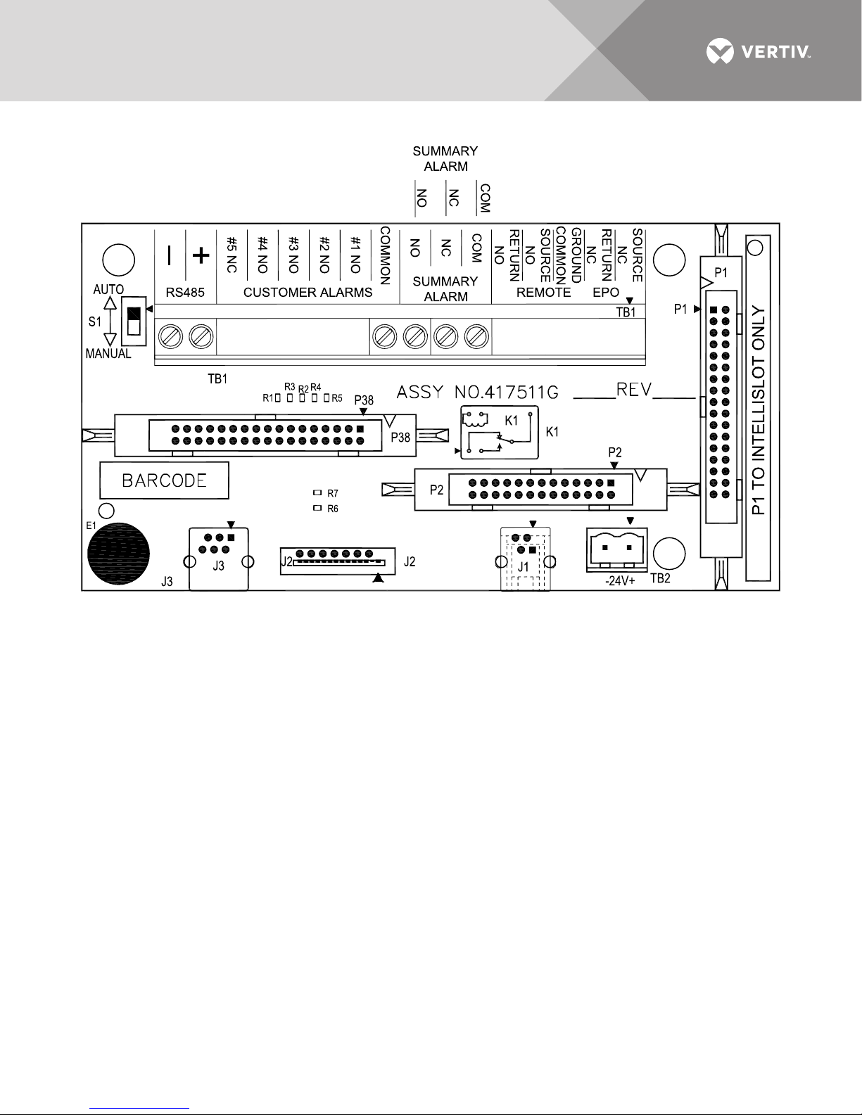
Figure 11 Electrical field connections for Liebert LDMF™ summary alarm
LDM13008
Rev. 0
1.10 Liebert LDMF Communication
Connecting locally to the Liebert LDMF Monitoring option requires a female-to-female (F-F) DB9
null modem cable. There will be an external port on the Liebert RX labeled LDMF SETUP.
Connect the DB9 null modem cable to a local PC. Once connected you may run any of the
provided software tools that can be downloaded from the Support area of the Vertiv Web site,
www.vertivco.com (see the Liebert LDMF user manual, SL-20200, for details on downloading
and using the software).
Vertiv | Liebert® RX™ Remote Distribution Cabinet User Manual | 19
Page 24
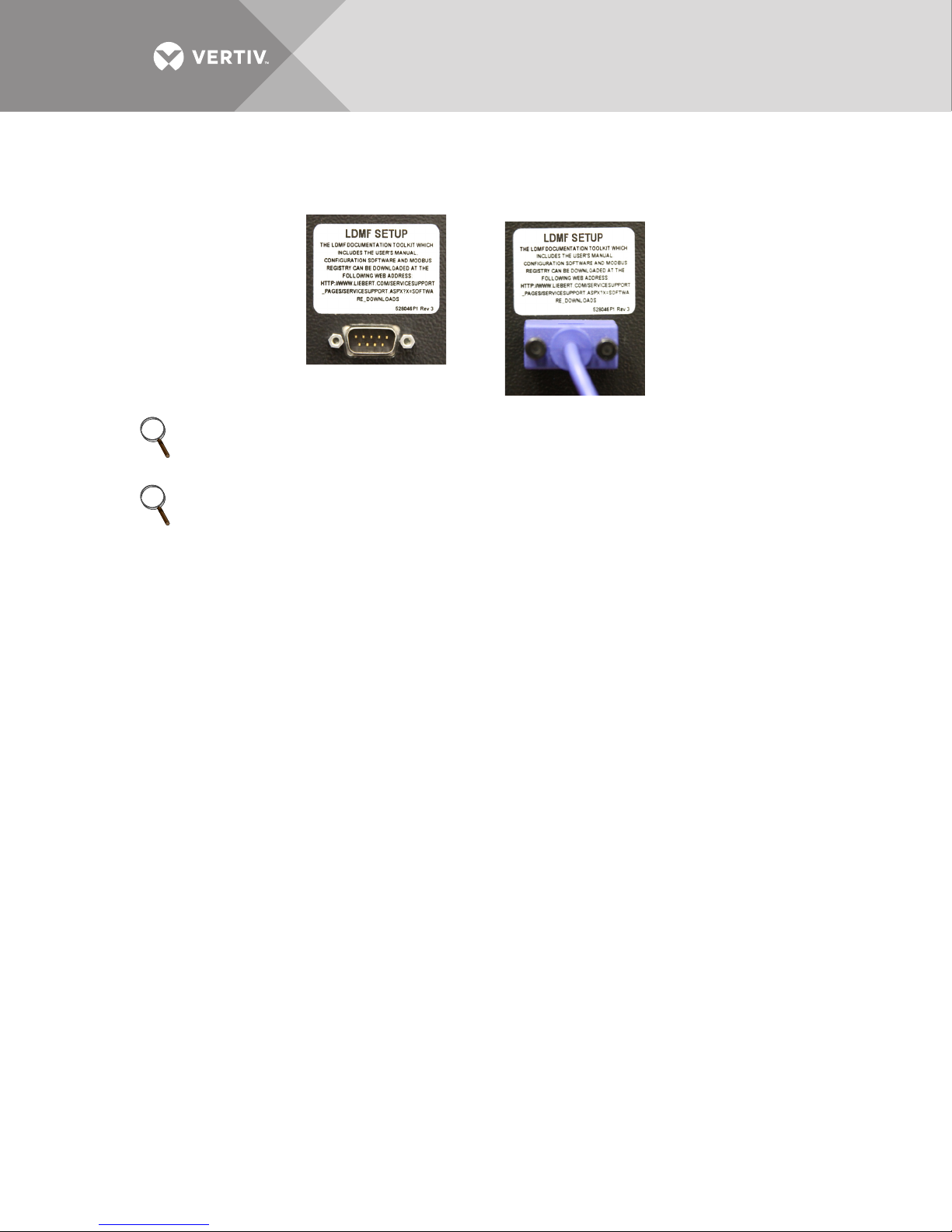
1.10.1 LDMF Setup Port Connection
NOTE
Also refer to
The local LDMF Setup port is not intended to be a service terminal or hyperterminal connection.
It is intended only for use of the Liebert LDMF software tools provided.
NOTE
The images above are intended for illustration only. The location of the external port may vary.
NOTE
Before making any changes to an existing configuration or uploading a file to another Liebert
™
LDMF
file due to changes, modifications or breaker addition/deletion, the Software Address will revert
to the value of the file that is loaded. This can lead to incorrect Software Addresses causing
Modbus communication errors.
system, make a note of the Software Address. When overwriting an existing configuration
1.10.2 Liebert SiteScan® Web Monitoring Interface
The optional monitoring interface module allows the Liebert LDMF to communicate with Liebert
SiteScan Web 4.0 or greater. The option includes software and graphics that support up to 168
branch breakers using an Ethernet connection. The monitoring interface is on the back of the
Liebert RX front door and has connections for RJ-45 Ethernet and BACnet. See Figure 8 for
location and wiring details.
1.10.3 Summary Alarm
The Liebert LDMF provides a Form C (one NO and one NC) summary alarm contact for remote
alarm status. The summary alarm contacts change state upon occurrence of any alarm including
warnings and reset when the alarm is cleared. The summary alarm connection is on the Adapter
Board (see Figure 8, Detail A, and Figure 11) marked Summary Alarm (NC) (NO) and (COMM).
The contacts are rated at 24VAC at 1A.
Vertiv | Liebert® RX™ Remote Distribution Cabinet User Manual | 20
Page 25
2.0 EQUIPMENT INSPECTION AND STARTUP
2.1 Internal Inspection
A detailed internal inspection should be performed after the unit is in place and before it is
energized, to ensure trouble-free startup. The same internal inspection should be carried out
when performing preventive maintenance.
WARNING
Risk of electric shock. Can cause personal injury or death.
Verify that all incoming power circuits are de-energized and locked out before performing
the internal inspection.
Gain access to the internal components of the Liebert RX by opening the accent panel.
Inspect the wiring and components to be sure they are not damaged.
Check all power connections for tightness. Refer to Tab le 1 for torque requirements of all
electrical connections
Follow the procedures described in 3.0 - Inspection and Startup Checklist when performing a
detailed inspection.
Table 1 Maximum wire range recommended torque values
Terminal Connector Max. Wire Range Torque, in/lb
Main Lug No. 3/0-500 MCM Copper 275
Ground Main No. 6-250 MCM Cu 200
Ground Neutral Bar
1/4" Holes
(No. 14-4 AWG)
5/16" Holes
(No.14-2 AWG)
Connector Mounting Hardware
1/2"-13 Bolt and Nut — 480
QOB Breaker Connector Screw — 18-21
See branch breaker for lug torque.
No. 14-10 Copper
No. 8 Copper
No. 6-4 Copper
No. 2 Copper
20
25
35
50
2.2 Startup
Follow the detailed step-by-step checklist in 3.0 - Inspection and Startup Checklist when
installing and starting up the Liebert RX.
A qualified electrician should be employed to perform the equipment inspection and startup.
System startup may be arranged by calling your local Vertiv sales representative or Vertiv. In the
USA, call 1-800-543-2378.
Vertiv | Liebert® RX™ Remote Distribution Cabinet User Manual | 21
Page 26

A copy of the appropriate checklist (furnished with the equipment) must be completed, signed,
dated and returned to Vertiv. Warranty coverage of the equipment is not effective unless the
Checklist is received by the factory.
WARNING
Risk of improper startup. Can cause equipment damage, personal injury and death.
Hazardous voltages are present during startup procedures. Electrical safety precautions
must be followed throughout inspection and startup.
Equipment inspection and startup should be performed only by properly trained and
qualified personnel wearing appropriate safety headgear, gloves and shoes.
Vertiv | Liebert® RX™ Remote Distribution Cabinet User Manual | 22
Page 27
3.0 INSPECTION AND STARTUP CHECKLIST
Unit Serial Number:
Unit Model Number:
Date:
3.1 Inspection
WARNING
Risk of electric shock. Can cause personal injury or death.
Lethal voltages are present during startup procedures. Electrical safety precautions must
be followed throughout inspection and startup. Verify that all incoming power circuits are
de-energized and locked out before performing any internal inspection.
Exterior Inspection
___ 1. Confirm that the exterior of unit is undamaged.
___ 2. Confirm that service and ventilation clearances are adequate. (See 1.5 - Configurations for Liebert RX
Installation).
Interior Inspection
___ 1. Open the accent panel.
___ 2. Inspect all wire and conductor insulation for damage.
___ 3. Check all breaker connections for tightness. Retorque if necessary.
___ 4. Check trip settings of adjustable breakers.
___ 5. Check all terminal block connections for tightness. Retorque if necessary.
___ 6. Remove any foreign objects from the components or the interior area of the unit.
___ 7. Check that the intake and exhaust air screens are clean and free of obstructions.
___ 8. Close the accent panel, leaving access to circuit breakers for the following startup procedure.
Vertiv | Liebert® RX™ Remote Distribution Cabinet User Manual | 23
Page 28
3.2 Startup
WARNING
Risk of electric shock. Can cause personal injury or death.
Hazardous voltages are present in the equipment throughout the startup procedure. This
unit has several circuits that are energized with high AC voltage.
Only properly trained and qualified personnel wearing appropriate safety headgear, gloves,
shoes and glasses should be involved in starting this unit. When performing any procedure
with any part of the equipment under power, personnel and test equipment should be
standing on rubber mats.
In case of fire involving electrical equipment, use only carbon dioxide fire extinguishers or
those approved for use in fighting electrical fires.
One person should never work alone, even if all power is disconnected from the equipment.
A second person should be standing by to assist and to summon help in case of an
accident.
___ 1. Make certain that all circuit breakers are in the Off position and that power to the unit is locked out.
___ 2. Turn On the building power to the unit. Check the phase rotation at the panelboard main breaker or
panelboard input lugs if no panelboard main breaker is supplied. Phase rotation should be A, B, C, as
indicated.
___ 3. Check and record the input voltages at the panelboard main breaker or panelboard input lugs if no
panelboard main breaker is supplied:
I np ut 1 In pu t 2 In p ut 3 In pu t 4
Volts, phase A to phase B =
Volts, phase B to phase C =
Volts, phase C to phase A =
___ 4. Turn Off and lock out the building power to the unit.
___ 5. Replace the junction box cover.
___ 6. Verify proper input power connections to unit, including equipment grounding conductor.
___ 7. Turn On the building input power to the unit.
___ 8. Check the phase rotation at the panelboard main breaker. Phase rotation should be A, B, C, left to right.
___ 9. Check and record the input voltage at the panelboard main breaker. Measured voltages should
correspond to the unit’s nameplate input voltage.
Pa n el b oa rd 1
Volts, phase A to phase B =
Volts, phase B to phase C =
Volts, phase C to phase A =
If output voltage is incorrect, check for wiring errors or incorrect input voltage. Contact Vertiv at 1-800-5432378 in the USA or the local factory representative for assistance.
___ 10. Turn On the panelboard main breaker.
3.3 Monitoring System Check Out
If the unit is equipped with Current Plus Monitoring or Liebert LDMF™:
1. Turn the unit On.
2. Ensure that the LCD is On. The Monitor Panel displays output and neutral currents for the panelboard
(load must be applied to get an accurate reading).
Vertiv | Liebert® RX™ Remote Distribution Cabinet User Manual | 24
Page 29

4.0 OPERATING INSTRUCTIONS
4.1 Startup Procedures
Before the unit is placed in service after initial installation, after equipment relocation or after
equipment has been de-energized for an extended period of time, perform equipment inspection
and startup procedures as detailed in 2.0 - Equipment Inspection and Startup and in 3.0 -
Inspection and Startup Checklist.
After initial system startup, the following guidelines can be used for standard equipment
operation. These guidelines should be reviewed for any special equipment modifications, special
site considerations or company policies that may require changes to the standard equipment
operation.
4.2 Normal System Shutdown
To perform a normal system shutdown, perform an orderly load equipment shutdown according
to the load equipment manufacturer’s recommended shutdown sequence. The load equipment
can be turned Off at each piece of load equipment or at the Liebert RX panelboards (circuit
breaker) located behind the unit’s front door. Turn Off the unit panelboard main breaker. To
remove all power from the unit, turn Off the building power to the unit.
4.3 Normal System Turn On
Make certain all unit circuit breakers are in the Off position. All unit circuit breakers are located
behind the front door. Turn On building power to the unit. Turn On the panelboard main circuit
breakers if supplied. If the circuit breaker has been tripped Off (instead of being turned Off), the
circuit breaker handle must be moved to the Off position before being turned On. Individually turn
On each panelboard circuit breaker following the load equipment manufacturer’s startup
sequence.
4.4 Current Plus Monitoring—Optional
The Liebert RX has a Current Plus Monitoring (CPM) feature that monitors the current and
voltage of the panelboard. The CPM includes a monochrome liquid crystal display (LCD) with
power and alarm LEDs, an audible alarm and a Silence push button.
The CPM displays the power parameters and alarms listed below for each panelboard.
The CPM displays circuit identification, the status of each breaker and the following parameters:
•Voltage—Line-to-Line
• Voltage—Line-to-Neutral
• Neutral Current
• Ground Current
•kVA
• Power Factor
• Voltage Total Harmonic Distortion (THD)
• Current Total Harmonic Distortion (THD)
•Crest Factor
Vertiv | Liebert® RX™ Remote Distribution Cabinet User Manual | 25
Page 30

The CPM annunciates alarm messages for the following conditions. Alarm thresholds for
monitored parameters are adjustable through the service port to match site requirements. The
alarms and their factory setpoints for the alarms are:
Alarm Default Setpoint
• Overvoltage A line-to-line voltage is more than 6% above
nominal
• Undervoltage A line-to-line or line-to-neutral voltage is 13% below
nominal
• Neutral Overcurrent Current exceeds 95% of breaker amps
• Ground Overcurrent Current exceeds 5 amps
• Phase Overcurrent
Warning
• Phase Overcurrent Current exceeds 80% of breaker amps
• Summary Alarm
Current exceeds 75% of breaker amps
Summary Alarm—detects and annunciates upon occurrence of any alarm.
Summary Alarm Contacts—The CPM has a Form C (1 NO and 1 NC) summary alarm contacts
for remote alarm status. The contacts are rated at 24VAC @ 1A. The contacts change state when
any alarm or warning occurs and reset when the alarm is cleared.
To facilitate troubleshooting, all alarms are stored in non-volatile memory to protect against
erasure by a power outage. Alarms must be manually reset after alarm conditions are corrected.
Communication—Remote communication and summary alarm connections are available.
A Liebert IntelliSlot® card provides connection to a Building Management System (BMS) or to
Liebert SiteScan® monitoring using RS485, see Figure 9. The following cards are available:
• IS-WEBS card for SNMP/Web output to Ethernet LAN
• (IS-485S card for Modbus 485 output using a two-wire connection
• IS-IPBMS card for Modbus IP output using an RJ-45 connection
• IS-UNITY-DP card for HTTP/HTTPS, Vertiv Protocol, e-mail, SMS, SNMP v1/v2c/v3, BACnet IP/MSTP
and Modbus TCP/RTU output using a serial RS-485 two-wire connection
Check the Liebert IntelliSlot ports on the back of the door to determine which cards are supplied;
more than one card might be supplied. See Figures 7, 8 and 12 for location and connection
details.
WARNING
Risk of electric shock. Can cause personal injury or death.
Verify that the panelboard voltage (power) circuit is de-energized and locked out before
installing branch breakers and cables.
Vertiv | Liebert® RX™ Remote Distribution Cabinet User Manual | 26
Page 31
4.5 Liebert LDMF™—Optional
If the Liebert RX is equipped with the optional Liebert LDMF, the monitoring unit is On whenever
power is supplied to the unit. The Liebert LDMF is factory-configured for 1-pole, 20A branch
breakers. Alarms, alarm setpoints, circuit breaker names and circuit breaker ratings are all fieldadjustable through the DB9 connector (LDMF SETUP port; see Figure 8).
For more information, refer to 1.10 - Liebert LDMF Communication for communication options
and connections and the Liebert LDMF user manual (SL-20200).
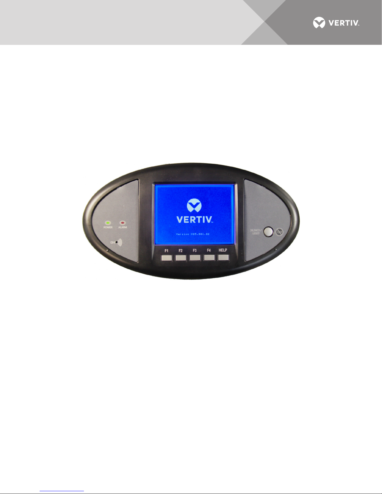
The Liebert LDMF local display allows users to view monitoring information for the panelboard as
well as each individual branch circuit breaker. Alarm data can be viewed from the local display for
up-to-date breaker status.
Figure 12 Liebert LDMF local display
Vertiv | Liebert® RX™ Remote Distribution Cabinet User Manual | 27
Page 32
5.0 MAINTENANCE
5.1 Repair
Even the most reliable equipment may fail. Vertiv is at your service to assure fast repair of your
unit and minimum down-time of your installation.
WARNING
Risk of electric shock. May cause personal injury or death.
Only properly trained and qualified service personnel wearing appropriate safety headgear,
gloves, shoes and glasses should perform maintenance on the Liebert RX. All voltage
sources to the unit must be disconnected before inspecting or cleaning within the cabinet.
Standard electrical troubleshooting procedures should be used to isolate problems in the unit. If
there are questions, don’t hesitate to contact Vertiv.
Repair or replacement of standard items, such as circuit breakers and fuses can be either handled
by qualified electricians or referred to Vertiv.
Repairs related to the monitoring system should be referred to Vertiv.
To contact Vertiv for information or repair service in the USA, call 1-800-543-2378.
5.2 Inspection & Cleaning
Air circulation through the cabinet may cause dust to accumulate on internal components.
Cleaning should be done as necessary during electrical inspections.
Annual general system inspections, cleaning and operation checks are recommended to ensure
system performance and long service life.
WARNING
Risk of electric shock. May cause personal injury or death.
Only properly trained and qualified service personnel wearing appropriate safety headgear,
gloves, shoes and glasses should perform maintenance on the Liebert RX. All voltage
sources to the unit must be disconnected before inspecting or cleaning within the cabinet.
5.2.1 Inspection Schedule
• It is difficult to establish a schedule for periodic cleaning because conditions vary from site to site.
Inspections after the first 24 hours, after 30 days and after 6 months of operation should help determine a
pattern for the inspection schedule.
• Electrical connections and component mountings should be inspected after the first 24 hours, after
30 days and after 6 months of operation. Inspections should be conducted annually thereafter.
• Ventilation openings and grilles should be inspected and cleaned every 6 months to one year.
• A complete inspection and operational checkout should be performed annually. This is best done by
performing the inspection and startup procedure as detailed in 3.0 - Inspection and Startup Checklist.
• Vertiv offers a complete range of preventive maintenance services. These include thorough equipment
performance checks and calibration of electronics. Contact Vertiv in the USA (1-800-543-2378) for
details.
Vertiv | Liebert® RX™ Remote Distribution Cabinet User Manual | 28
Page 33

Page 34

VertivCo.com | Vertiv Headquarters, 1050 Dearborn Drive, Columbus, OH, 43085, USA
© 2018 Vertiv Co. All rights reserved. Vertiv and the Vertiv logo are trademarks or registered trademarks of Vertiv Co. All other names and logos referred to
are trade names, trademarks or registered trademarks of their respective owners. While every precaution has been taken to ensure accuracy and
completeness herein, Vertiv Co. assumes no responsibility, and disclaims all liability, for damages resulting from use of this information or for any errors or
omissions. Specifications are subject to change without notice.
SL-20501_REV6_8-18
 Loading...