

Page 1

Liebert® PSA4™ 500– 700VA
Installer/User Guide
Page 2

Technical Support Site
If you encounter any installation or operational issues with your product, check the pertinent section of
this manual to see if the issue can be resolved by following outlined procedures. For additional assistance,
visit https://www.VertivCo.com/en-us/support/
Page 3

TABLE OF CONTENTS
1 Liebert PSA4 Overview 5
1.1 Controls and Indicators 6
1.2 Installation 7
1.3 Setup and Start-up 7
1.4 UPS Operation 8
1.5 Alarms 8
1.5.1 On Battery 8
1.5.2 Low Battery Warning 8
1.5.3 Weak/Bad Battery 8
1.5.4 Overload 8
1.5.5 UPS Fault 9
1.6 Troubleshooting 9
1.7 Maintenance and Battery Replacement 9
1.7.1 Battery Charging 9
1.7.2 Precautions 9
1.7.3 Battery Replacement Precaution 10
1.7.4 Information for the Protection of the Environment 10
1.7.5 Battery Replacement Procedure 10
1.7.6 Specifications 12
Appendices 15
Appendix 1: Technical Support 15
Vertiv | Liebert® PSA4™ Installer/User Guide | 3
Page 4

Vertiv | Liebert® PSA4™ Installer/User Guide | 4
Page 5

1 LIEBERT PSA4 OVERVIEW
Thank you for purchasing the Liebert PSA4 Uninterruptible Power Supply. It is designed, manufactured,
and tested to provide many years of reliable power protection.
Please review this manual and the important safety instructions before installing, operating, or
maintaining your Liebert PSA4 UPS.
CAUTION: Connect the UPS only to a properly grounded/earthed outlet that is protected by an
appropriate branch circuit protector (circuit breaker or fuse) that meets national and/or local
electrical codes.
The Liebert PSA4 should be located near the wall outlet. Do not use extension cords between the wall
outlet and the UPS. The Liebert PSA4 is designed for small office and home use only. It is not
recommended to be used with life-support equipment or applications.
WARNING: Risk of Electric Shock. Observe all cautions and warnings in this manual. Failure to
do so may result in serious injury or death. Refer all UPS and battery service to properly trained
and qualified service personnel. Do not attempt to service this product yourself beyond the
battery replacement procedures. Opening or removing the cover may expose you to lethal
voltages within this unit even when it is apparently not operating and the input wiring is
disconnected from the electrical source. Never work alone.
In case of fire, use a dry chemical fire extinguisher to put out the fire. Using a fluid fire extinguisher may
cause electric shock. In the event of an emergency, press and hold the ON/OFF button for at least one (1)
second to turn off the UPS then unplug the UPS from the wall outlet.
NOTICE: This equipment has been tested and found to comply with the limits for a Class B computing
device in accordance with the specifications in Subpart J of Part 15 of FCC Rules and also meets the Class
B limits for radio noise emissions from digital apparatus set out in the Radio Interference of the Canadian
Department of Communications. These limits are designed to provide reasonable protection against such
interference in a residential installation. This equipment generates and uses radio frequency and if not
installed and used properly, that is, in strict accordance with the manufacturer's instructions, this
equipment may cause interference to radio and television reception. If this equipment does cause
interference to radio or television reception, which can be determined by turning the equipment off and
on, the user is encouraged to try to correct the interference by one or more of the following measures:
• Re-orient the receiving antenna.
• Relocate the computer with respect to the receiver.
• Move the computer away from the receiver.
• Shielded communication-interface cables must be used with this product.
WARNING: Changes or modifications to this unit not expressly approved by the party
responsible for compliance could void the user's authority to operate the equipment.
Vertiv | Liebert® PSA4™ Installer/User Guide | 5
Page 6
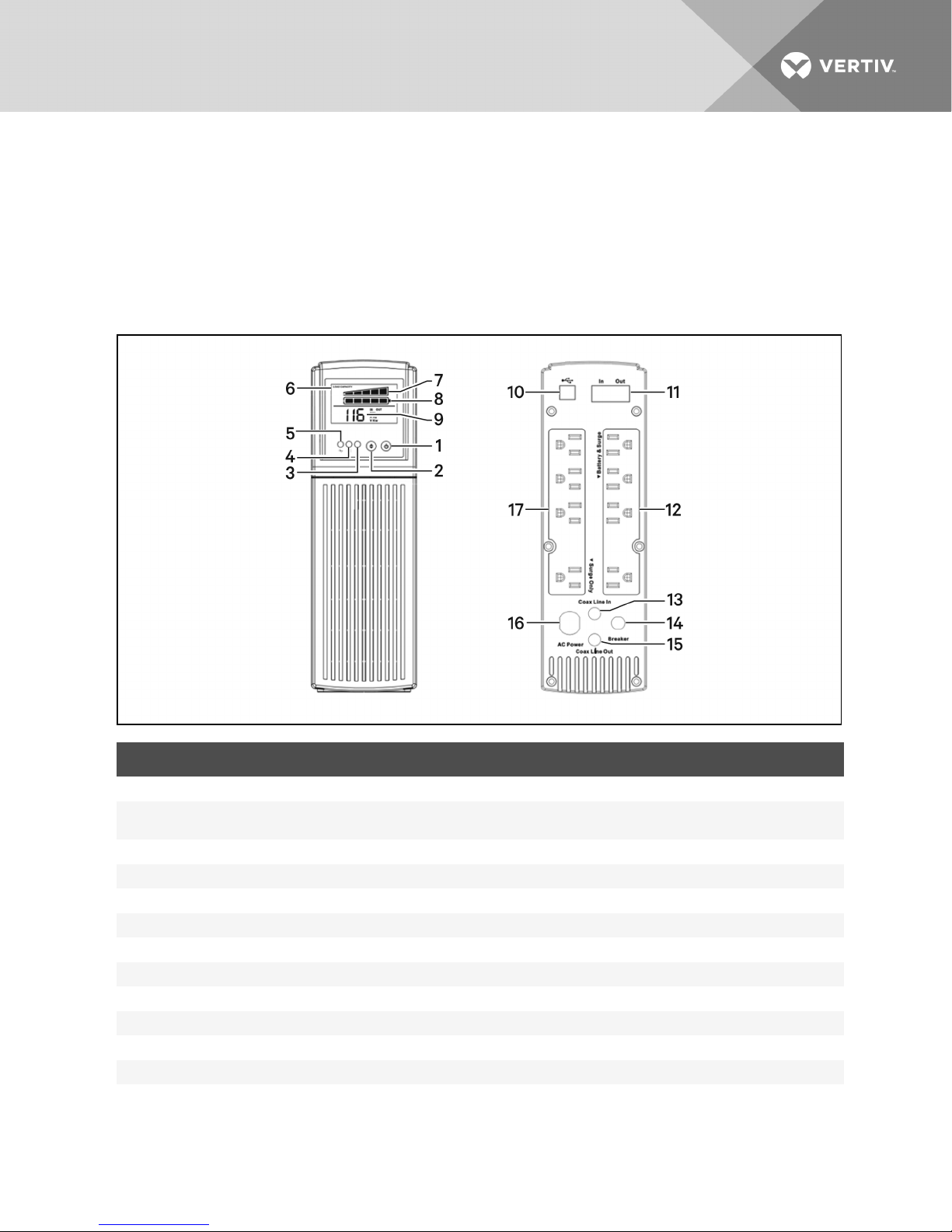
The Liebert PSA4 is shipped with the following items:
• CD with Liebert MultiLink® Shutdown Software and User manual (electronic version)
• USB cable; one 1.8m (6 ft.) long
• Coax cable; one 1m (3ft.) long
• User Manual with warnings safety instructions and WEEE recycling sheet
(ISO14001compliance)
1.1 Controls and Indicators
ITEM DESCRIPTION
1 On/Off button.
2
3 Fault LED (red).
4 Battery operation LED (amber).
5 On Ut ility LED (green).
6 LCD display with icons and:
7 State 1: Load Capacity bar in 20% increments.
8 State 2: Batt ery Capacity barin 20% increments.
9 State 3: Numeric information to display UPS operational parameters.
10 Type B USB port for USBcommunication, monitoring and control.
11 RJ11/45 connectors for phone/fax/modem or network surgeprotection.
12 Battery-backed andsurge-protect ed output power receptacles.
13
Scroll button.
To scroll throughthe LCD-display parameters and, when on battery power, silences the audiblealarm.
Coax CableLine In
for cablemodem, DSS receiver, or cable-TV converter surge protection.
Vertiv | Liebert® PSA4™ Installer/User Guide | 6
Page 7

ITEM DESCRIPTION
14
15
16 Input Power Cord.
17 Surge-protected-only output-power receptacles.
Input Circuit Breaker.
The input circuit breaker trips if the output load exceeds t he UPS'spower rating.
Coax CableLine Out
for cablemodem, DSS receiver, or cable-TV converter surge protection.
1.2 Installation
Install the Liebert PSA4 in a temperature-controlled environment that is free of corrosive and conductive
contaminants. Avoid locations near heat or water sources and exposed to direct sunlight. For proper
ventilation, leave approximately 2 to 4 inches clearance on all sides of the UPS.
The UPS unit ships with the internal battery connected.
1.3 Setup and Start-up
Inspect the UPS for any signs of obvious damage. If damage is visible, do not proceed with the setup and
call our warranty support line for a new replacement unit.
The UPS has 4 battery-backed and surge-protected receptacles and 4 surge-protected-only receptacles.
Plug your critical equipment (such as computer, monitors, etc.) into the battery-backed receptacles and
your less-critical equipment (such as printers and other less-often used peripherals) into the surge-only
receptacles.
If you also want to protect your computer network connection or telephone, you can use the
network/telephone surge-protection ports on the side. Use the “IN” port to connect the line from the wall
jack and the “OUT” port to connect to your device port. Use of this feature is not required forproper
operation of the UPS.
If you also want to protect your cable modem, DSS Receiver, or cable-TV converter connection you can
use the Coax surge protection ports on the side of the UPS. Use the “IN” port to connect the line from the
wall jack and the “OUT” port to connect to your device port. Use of this feature is not required for proper
operation of the UPS.
If you wish to use the USB communications, plug the provided cable into the port on the UPS and the
other end into an open USB port on your computer. This allows unattended shutdown of your computer
using either the built-in feature within the Microsoft® Windows® operating system or the Liebert
Multilink® Shutdown software located on the CD that shipped with the UPS. Use of this feature is not
required for proper operation of the UPS.
You are now ready to start the UPS. Plug the UPS input cord into the wall outlet. To turn on the UPS, press
and hold the ON/OFF button until you hear the UPS beep, then release the button. The connected
equipment immediately receives power and the UPS starts a short, self system test (electronics and
battery check). When the unit passes all self checks, only the green LED should be lit indicating normal
operation.
NOTE: While every precaution has been taken to ensure that the battery is in good condition, we
recommend allowing the UPS to charge the battery for at least 4 hours prior to providing full back-up
time protection for any utility-power abnormality.
Vertiv | Liebert® PSA4™ Installer/User Guide | 7
Page 8

1.4 UPS Operation
The UPS is designed for easy operation. Once the UPS is plugged into the wall outlet, it begins to charge
the battery whether the UPS has been turned on or not.
To turn on the UPS, press and hold the ON/OFF button until the unit beeps, then release the button.
To turn off the UPS, press and hold the ON/OFF button for at least 1 second then release the button. To
completely stop all UPS operation, once the UPS is turned off, unplug the input cord from the wall outlet.
During normal operation, the UPS protects the connected equipment from utility abnormalities, such as
brownout/sags, over-voltage/surges, and complete outages. During utility sags and surges, the UPS AVR
circuits will either Boost or Buck the input voltage to correct the voltage for the connected equipment
that is plugged into the battery-backed outlets. During utility outages the UPS automatically draws power
from the battery to support the connected equipment that is plugged into the battery-backed outlets.
Note that equipment plugged into the surge-only outlets shut down in these conditions. If the utility
power problems are long-term, the UPS will eventually shut down because all battery power is exhausted.
Once utility power is restored to normal operating parameters for the UPS, it automatically restarts and
begins to power the connected equipment and to recharge the battery for the next utility abnormality.
1.5 Alarms
1.5.1 On Battery
When the UPS is operating on the batteries, the On Battery LED illuminates and the audible alarm sounds
once every 5 seconds. The alarm stops once the UPS returns to the AC normal mode.
1.5.2 Low Battery Warning
The UPS sounds 2 beeps every 5 seconds and the On Battery LED blinks on/off when the battery reserve
runs low. This condition continues until AC returns or the UPS shuts down from battery exhaustion.
1.5.3 Weak/Bad Battery
The UPS automatically tests the battery's condition and, if the battery fails the test because of weak
capacity, bad battery, or battery disconnected:
• The Fault LED flashes on/off
• The Battery Capacity bar graph may show no segments.
• The alarm beeps 3 times every 30 seconds until the battery is reconnected or replaced.
We recommend that the UPS charge overnight before performing a battery test to confirm a Weak/Bad
Battery condition.
1.5.4 Overload
When the amount of equipment connected to the UPS exceeds its power rating, the the Load Capacity
bar graph is “full,” the Fault LED flashes on/off, and the UPS sounds 1 beep every half second (AC and
Battery modes). The alarm remains on until the excess load is removed or the UPS's self-protection circuit
shuts down the UPS.
Vertiv | Liebert® PSA4™ Installer/User Guide | 8
Page 9

1.5.5 UPS Fault
When the UPS detects a hardware fault, the Fault LED illuminates, the output power turns off, and the
UPS sounds a constant alarm. The fault condition, in some instances, may be reset by turning the UPS off
and then back on.
1.6 Troubleshooting
SYMPTOM POSSIBLE CAUSE WHAT TO DO
UPS will not turn on. On/Off/ button not pressed. Press and release t he On/Off button t o start UPS.
UPS operates in battery mode
only, even though normal AC
power is present.
Fault LED is illuminated.
The AC mode LED is illuminated,
but thereis no output.
The AC Mode LED is blinking
UPS does not provide expect ed
runtime.
Battery Capacity bar graph is
flashing on andoff.
Load Capacity bar graph is
flashing on andoff.
Input AC circuit breaker is
tripped.
UPS has detected an
internal fault.
The UPSis being c ontrolled
via its communications port.
The UPSis in “buck” or
“boost” operating mode.
The batteries may beweak
or at the endof useful
service life.
Loose connections at the
batteries, Weak batteries,
Bad batteries.
The load has exceeded the
UPS's capacity.
Reset circuit breaker by pressing the plunger back in. If the AC circuit breaker trips
after UPS st arts up, reduce the load on the UPS.
Call f or areplacement unit.
Disconnect the computer cable from the UPSand press the On button. If UPS works
normally, the software has control of the UPS. If the UPS still does not have output
power, call for service.
The UPSis operating normally, correcting abnormal input power.
Charge the batteries for 8-hours and retest. If the run time is still less than expected,
the batteries may need replaced, even though the Weak/ Bad Battery alarm is not
sounding.
Check battery connections, chargethe batteries for 8-hours, replace the batteries.
Check the "Specifications" on page12 t able that follows. Remove part of the load.
1.7 Maintenance and Battery Replacement
1.7.1 Battery Charging
The batteries are valve-regulated, non-spill-able, lead acid and should be kept charged to attain their
design life. The Liebert PSA4 charges the batteries continuously when it is connected to the utility input
power. If the Liebert PSA4 will be stored for a long time, we recommend connecting the UPS to input
power for at least 24 hours every 4 to 6 months to ensure full recharge of the batteries.
1.7.2 Precautions
Although the Liebert PSA4 is designed and manufactured to ensure personal safety, improper use can
result in electrical shock or fire. To ensure safety, observe the following precautions:
• Turn off and unplug the UPS before cleaning it.
• Clean the UPS with a dry cloth. Do not use liquid or aerosol cleaners.
• Never block or insert any objects into the ventilation holes or other openings of the UPS.
• Do not place the UPS power cord where it might be damaged.
Vertiv | Liebert® PSA4™ Installer/User Guide | 9
Page 10
1.7.3 Battery Replacement Precaution
Before proceeding, please review the battery safety precautions.
WARNING: Risk of electric shock and explosion. Can cause equipment damage, injury and
death. Do not dispose of the battery in a fire. The battery may explode. Do not open or damage
the battery. Released electrolyte is toxic and is harmful to skin and eyes. If electrolyte comes
into contact with the skin, wash the affected area immediately with plenty of clean water and
get medical attention.
WARNING: Risk of electric shock. Can cause equipment damage, injury and death.
A battery can present a risk of electrical shock and high short-circuit current. The following
precautions should be observed when working on batteries:
- Remove watches, rings and other metal objects.
- Use tools with insulated handles.Wear rubber gloves and boots.
- Do not lay tools or metal parts on top of batteries.
- Disconnect charging source prior to connecting or disconnecting battery terminals.
- Determine if the battery is inadvertently grounded. If it is inadvertently grounded, remove the
source of the ground. Contact with any part of a grounded battery can result in electrical
shock. The likelihood of such shock will be reduced if grounds are removed during installation
and maintenance (applicable to a UPS and a remote battery supply not having a grounded
supply circuit).
1.7.4 Information for the Protection of the Environment
UPS SERVICING - This UPS makes use of components dangerous for the environment (electronic cards,
electronic components). The components removed must be taken to specialized collection and disposal
centers.
NOTICE TO ALL CUSTOMERS: DISPOSAL OF OLD APPLIANCES - This product has been
supplied from an environmentally aware manufacturer that complies with the Waste
Electrical and Electronic Equipment (WEEE) Directive 2002/96/CE. The “crossed-out
wheelie bin” & recycle symbol is placed on this product to encourage you to recycle
wherever possible. Please be environmentally responsible and recycle this product through
your recycling facility at its end of life. Do not dispose of this product as unsorted municipal
waste. Follow local municipal waste ordinances for proper disposal provisions to reduce the
environmental impact of waste electrical and electronic equipment (WEEE).
1.7.5 Battery Replacement Procedure
1. Turn the UPS on its side.
2. Remove and set aside the two battery-compartment retaining screws (item1).
3. Slide the battery compartment cover outward and lift-off to expose the battery (item2).
4. Grasp the battery and gently pull it out far enough to disconnect the battery wires.
5. Disconnect the battery positive (Red) wire and the battery negative (Black) wire. (item3).
6. Remove the battery and set aside.
Vertiv | Liebert® PSA4™ Installer/User Guide | 10
Page 11
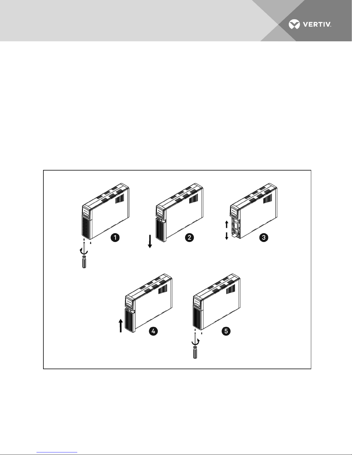
7. Orient the new battery in the same direction as the original battery and place the new battery
close enough to connect the battery wires.
NOTE: Replace the battery with the same type and number as originally installed.
8. Connect the battery negative (Black) wire to the battery negative terminal.
9. Connect the battery positive (Red) wire to the battery positive terminal.
NOTE: When connecting the last wire to the battery, there can be a small spark, thisisnormal.
10. Fully insert the new battery into the UPS and re-install the battery compartment cover
(item4).
11. Re-install the battery compartment retaining screw (item 5).
12. Properly dispose of the old batteries at an appropriate recycling facility or return them to
Vertiv™ in the packing material for the new batteries.
13. The UPS is now ready for normal operation.
Vertiv | Liebert® PSA4™ Installer/User Guide | 11
Page 12

1.7.6 Specifications
Table 1.1 System Specifications
MODEL NUMBER PSA4-500MT120 PSA4-700MT120
Capacity (VA / W) 500 / 300 700 / 420
Unit Dimensions, in. (mm) W x D x H 3.43 x 10.2 x 10.6 (87x 260x 270)
Unit Weight, lbs (kg) 12.6 (5.7) 15.9 (7.2)
Shipping Dimensions,
in. (mm) W x D x H
Shipping Weight, lbs (kg) 17.6 (8.0) 19.8 (9.0)
Input AC
Nominal Voltage 120 VAC
Voltage Range 90-150 VAC
Frequency Range 50 or 60 Hz, ±5Hz, auto-sensing
Protection Resettable Circuit Breaker
SurgeEnergy Rating 320 Joules
Input Cord 6 f t. attached with NEMA 5-15P
Output AC (On Utility)
Nominal Voltage 120 VAC
Voltage Range 101-133 VAC
Frequency Range 50 or 60 Hz, ±5Hz, auto-sensing
Efficiency >90%at full load
Output AC (On Battery)
Nominal Voltage 120 VAC
Voltage Range Nominal ±6%
Frequency Range 50 or 60 Hz, ±1%
Waveform PWM Simulated Sine wave
Transfer Time 6 ms, typical
OverloadCapacity
Protection Electronic (over current, short circuit w/ latching shutdown)
Backup Time (Full Load / Half Load), min 2 / 8 2 / 7
Battery Type Valve Regulated Lead Acid (VRLA)
Battery Manufacturer / Model
Battery Quantity x VDC x Ah 1 x 12V x 5.0Ah 1 x 12V x 7.0Ah
Battery Backed Outlets (4) NEMA 5-15R
SurgeOnly Outlets (4) NEMA 5-15R
CSB / HR1221W
Leoch / DJW12-5.0
6.9 x 14.5 x 15.2 (175x 369x 385)
110% for 10 seconds,
120% immediate shutdown
CSB / GP1272
Leoch / DJW12-7.0
Vertiv | Liebert® PSA4™ Installer/User Guide | 12
Page 13

Table 1.1 System Specifications
MODEL NUMBER PSA4-500MT120 PSA4-700MT120
Environmental Requirements
Operating Temperature, deg(degC)
Operating Elevation, feet (meter)
Operating Temperature, degF (degC)
Operating Elevation, feet (meter)
Relative Humidity 0-95%non-condensing
Storage Temperature, degF (degC) 5 t o 113 (–15 to 45)
Storage Elevation, feet (meter) 0-49,212 (0-15,000)
Audible N oise <40 dBA @ 3 ft (1m) f rom all sides
Agency
Safety
RFI / EMI FCC Subpart J, Class B
SurgeImmunity ANSI 62.41 (IEC 62040-2 2nd Edition)
Transportation ISTA Procedure 1A
32-104(0-40)without derating
0-4,921 (0-1,500) without derating
32-95 (0-35) without derating
4,922-9,842 (1,500.5-3,000) without derating
Vertiv | Liebert® PSA4™ Installer/User Guide | 13
Page 14

This page intentionally left blank.
Vertiv | Liebert® PSA4™ Installer/User Guide | 14
Page 15

APPENDICES
Appendix 1: Technical Support
Our Technical Support staff is ready to assist you with any installation or operating issues you may
encounter with your Liebert product. Please call or e-mail us:
Technical support:
p: 1-800-222-5877 menu option 1
Monitoring support:
p: 1-800-222-5877 menu option 2
Warranty support:
p: 1-800-222-5877 menu option 3
Vertiv | Liebert® PSA4™ Installer/User Guide | 15
Page 16

This page intentionally left blank.
Vertiv | Liebert® PSA4™ Installer/User Guide | 16
Page 17

Page 18

VertivCo.com | Vertiv Headquarters, 1050 Dearborn Drive, Columbus, OH, 43085, USA
© 2017 Vertiv Co. Allrights reserved. Vertiv and the Vertivlogo are trademarks or registered trademarks of VertivCo. Allother names and logos referred to
are trade names, trademarks or registered trademarks of their respective owners. While every precaution has been taken to ensure accuracy and
completeness herein, Vertiv Co. assumes no responsibility, and disclaims allliability, for damages resultingfrom use of this information or for anyerrors or
omissions. Specificationsare subject to change without notice.
SL-23303_REV2_3-17/590-1413-501C
 Loading...