

Page 1

Liebert® PPC
™
Second Generation Power Conditioning and Distribution Cabinet
User Manual—Three-Phase, 15 - 225kVA, 50 & 60Hz
Page 2

Page 3

TABLE OF CONTENTS
IMPORTANT SAFETY INSTRUCTIONS . . . . . . . . . . . . . . . . . . . . . . . . . . . . . . . . . . . . . . . . . . . . . . . .1
1.0 INSTALLATION INSTRUCTIONS . . . . . . . . . . . . . . . . . . . . . . . . . . . . . . . . . . . . . . . . . . . . . . . 2
1.1 Unpacking and Installation . . . . . . . . . . . . . . . . . . . . . . . . . . . . . . . . . . . . . . . . . . . . . . . . . . . . . . . . . . . . . . . . . . . . . . . .2
1.1.1 Unpacking and Preliminary Inspection . . . . . . . . . . . . . . . . . . . . . . . . . . . . . . . . . . . . . . . . . . . . . . . . . . . . . . . . . . . . . 2
1.1.2 Handling Considerations . . . . . . . . . . . . . . . . . . . . . . . . . . . . . . . . . . . . . . . . . . . . . . . . . . . . . . . . . . . . . . . . . . . . . . . . . . 2
1.1.3 Unit Preparation . . . . . . . . . . . . . . . . . . . . . . . . . . . . . . . . . . . . . . . . . . . . . . . . . . . . . . . . . . . . . . . . . . . . . . . . . . . . . . . . . . 6
1.1.4 Location Considerations . . . . . . . . . . . . . . . . . . . . . . . . . . . . . . . . . . . . . . . . . . . . . . . . . . . . . . . . . . . . . . . . . . . . . . . . . . 6
1.1.5 Floor Pedestal Installation . . . . . . . . . . . . . . . . . . . . . . . . . . . . . . . . . . . . . . . . . . . . . . . . . . . . . . . . . . . . . . . . . . . . . . . . . 8
1.2 Distribution Sidecar Mounting and Wiring. . . . . . . . . . . . . . . . . . . . . . . . . . . . . . . . . . . . . . . . . . . . . . . . . . . . . . . . . 9
1.2.1 Sidecar Mounting . . . . . . . . . . . . . . . . . . . . . . . . . . . . . . . . . . . . . . . . . . . . . . . . . . . . . . . . . . . . . . . . . . . . . . . . . . . . . . . . . 9
1.2.2 Sidecar Electrical Connections . . . . . . . . . . . . . . . . . . . . . . . . . . . . . . . . . . . . . . . . . . . . . . . . . . . . . . . . . . . . . . . . . . . . 9
1.3 Power and Control Wiring . . . . . . . . . . . . . . . . . . . . . . . . . . . . . . . . . . . . . . . . . . . . . . . . . . . . . . . . . . . . . . . . . . . . . . . . 9
1.3.1 Input Power Connections . . . . . . . . . . . . . . . . . . . . . . . . . . . . . . . . . . . . . . . . . . . . . . . . . . . . . . . . . . . . . . . . . . . . . . . . 10
1.3.2 Junction Box Installation (If Used) . . . . . . . . . . . . . . . . . . . . . . . . . . . . . . . . . . . . . . . . . . . . . . . . . . . . . . . . . . . . . . . . 20
1.3.3 System Grounding . . . . . . . . . . . . . . . . . . . . . . . . . . . . . . . . . . . . . . . . . . . . . . . . . . . . . . . . . . . . . . . . . . . . . . . . . . . . . . . 22
1.3.4 Grounding Electrode Conductor (Units With Transformer). . . . . . . . . . . . . . . . . . . . . . . . . . . . . . . . . . . . . . . . . 22
1.3.5 Output Power Connections. . . . . . . . . . . . . . . . . . . . . . . . . . . . . . . . . . . . . . . . . . . . . . . . . . . . . . . . . . . . . . . . . . . . . . . 24
1.3.6 Control Wiring Connections . . . . . . . . . . . . . . . . . . . . . . . . . . . . . . . . . . . . . . . . . . . . . . . . . . . . . . . . . . . . . . . . . . . . . . 26
1.3.7 Adapter Board . . . . . . . . . . . . . . . . . . . . . . . . . . . . . . . . . . . . . . . . . . . . . . . . . . . . . . . . . . . . . . . . . . . . . . . . . . . . . . . . . . . 30
2.0 EQUIPMENT INSPECTION AND STARTUP . . . . . . . . . . . . . . . . . . . . . . . . . . . . . . . . . . . . . .31
2.1 Internal Inspection . . . . . . . . . . . . . . . . . . . . . . . . . . . . . . . . . . . . . . . . . . . . . . . . . . . . . . . . . . . . . . . . . . . . . . . . . . . . . . .31
2.2 Startup . . . . . . . . . . . . . . . . . . . . . . . . . . . . . . . . . . . . . . . . . . . . . . . . . . . . . . . . . . . . . . . . . . . . . . . . . . . . . . . . . . . . . . . . . .31
3.0 INSPECTION AND STARTUP CHECKLIST . . . . . . . . . . . . . . . . . . . . . . . . . . . . . . . . . . . . . 33
3.1 Inspection . . . . . . . . . . . . . . . . . . . . . . . . . . . . . . . . . . . . . . . . . . . . . . . . . . . . . . . . . . . . . . . . . . . . . . . . . . . . . . . . . . . . . . 33
3.2 Startup . . . . . . . . . . . . . . . . . . . . . . . . . . . . . . . . . . . . . . . . . . . . . . . . . . . . . . . . . . . . . . . . . . . . . . . . . . . . . . . . . . . . . . . . . 34
3.3 Monitoring System Check-Out. . . . . . . . . . . . . . . . . . . . . . . . . . . . . . . . . . . . . . . . . . . . . . . . . . . . . . . . . . . . . . . . . . . 35
3.4 Equipment Connection Check-Out (For Units With Distribution Cables) . . . . . . . . . . . . . . . . . . . . . . . . . . . 36
4.0 OPERATING INSTRUCTIONS . . . . . . . . . . . . . . . . . . . . . . . . . . . . . . . . . . . . . . . . . . . . . . . . . 37
4.1 Startup Procedures . . . . . . . . . . . . . . . . . . . . . . . . . . . . . . . . . . . . . . . . . . . . . . . . . . . . . . . . . . . . . . . . . . . . . . . . . . . . . 37
4.1.1 Emergency Shutdown. . . . . . . . . . . . . . . . . . . . . . . . . . . . . . . . . . . . . . . . . . . . . . . . . . . . . . . . . . . . . . . . . . . . . . . . . . . . 37
4.1.2 Normal System Shutdown. . . . . . . . . . . . . . . . . . . . . . . . . . . . . . . . . . . . . . . . . . . . . . . . . . . . . . . . . . . . . . . . . . . . . . . . 37
4.1.3 Normal System Turn ON . . . . . . . . . . . . . . . . . . . . . . . . . . . . . . . . . . . . . . . . . . . . . . . . . . . . . . . . . . . . . . . . . . . . . . . . . 37
4.1.4 Manual Restart . . . . . . . . . . . . . . . . . . . . . . . . . . . . . . . . . . . . . . . . . . . . . . . . . . . . . . . . . . . . . . . . . . . . . . . . . . . . . . . . . . 37
4.2 Basic Monitor Panel . . . . . . . . . . . . . . . . . . . . . . . . . . . . . . . . . . . . . . . . . . . . . . . . . . . . . . . . . . . . . . . . . . . . . . . . . . . . . 38
4.2.1 Display Controls and Indicators . . . . . . . . . . . . . . . . . . . . . . . . . . . . . . . . . . . . . . . . . . . . . . . . . . . . . . . . . . . . . . . . . . 38
4.3 Power Monitor Panel . . . . . . . . . . . . . . . . . . . . . . . . . . . . . . . . . . . . . . . . . . . . . . . . . . . . . . . . . . . . . . . . . . . . . . . . . . . . 39
4.4 Liebert Current Plus Monitoring (If Supplied) . . . . . . . . . . . . . . . . . . . . . . . . . . . . . . . . . . . . . . . . . . . . . . . . . . . . .41
4.5 Liebert Distribution Monitoring (If Supplied) . . . . . . . . . . . . . . . . . . . . . . . . . . . . . . . . . . . . . . . . . . . . . . . . . . . . . 43
5.0 MAINTENANCE . . . . . . . . . . . . . . . . . . . . . . . . . . . . . . . . . . . . . . . . . . . . . . . . . . . . . . . . . . . . . 45
5.1 Corrective Maintenance. . . . . . . . . . . . . . . . . . . . . . . . . . . . . . . . . . . . . . . . . . . . . . . . . . . . . . . . . . . . . . . . . . . . . . . . . 45
5.2 Preventive Maintenance (Inspection and Cleaning). . . . . . . . . . . . . . . . . . . . . . . . . . . . . . . . . . . . . . . . . . . . . . . 45
Vertiv |Liebert® PPC™ User Manual | Rev. 6 | 03/18 | i
Page 4

FIGURES
Figure 1 Typical cabinet and floor planning dimensions, sidecar . . . . . . . . . . . . . . . . . . . . . . . . . . . . . . . . . . . . . . . . .3
Figure 2 Typical cabinet and floor planning dimension data. . . . . . . . . . . . . . . . . . . . . . . . . . . . . . . . . . . . . . . . . . . . . 4
Figure 3 Typical cabinet and floor planning dimension data, top exit unit. . . . . . . . . . . . . . . . . . . . . . . . . . . . . . . . .5
Figure 4 Recommended minimum service and ventilation clearances . . . . . . . . . . . . . . . . . . . . . . . . . . . . . . . . . . . .7
Figure 5 Floor pedestal details . . . . . . . . . . . . . . . . . . . . . . . . . . . . . . . . . . . . . . . . . . . . . . . . . . . . . . . . . . . . . . . . . . . . . . . . .8
Figure 6 Electrical connection locations, sidecar unit. . . . . . . . . . . . . . . . . . . . . . . . . . . . . . . . . . . . . . . . . . . . . . . . . . . 11
Figure 7 Electrical connection location for 72-pole Square D or 54-pole GE panelboards, 32" cabinet,
bottom entry/exit . . . . . . . . . . . . . . . . . . . . . . . . . . . . . . . . . . . . . . . . . . . . . . . . . . . . . . . . . . . . . . . . . . . . . . . . . . . .12
Figure 8 Electrical connection locations, for 54-pole Square D or 42-pole GE panelboard, 32" cabinet,
bottom entry/exit . . . . . . . . . . . . . . . . . . . . . . . . . . . . . . . . . . . . . . . . . . . . . . . . . . . . . . . . . . . . . . . . . . . . . . . . . . . .13
Figure 9 Electrical connection location for 72-pole Square D or 54-pole GE panelboard, 44" cabinet,
bottom entry/exit . . . . . . . . . . . . . . . . . . . . . . . . . . . . . . . . . . . . . . . . . . . . . . . . . . . . . . . . . . . . . . . . . . . . . . . . . . . .14
Figure 10 Electrical connection locations, 54-pole Square D or 42-pole GE panelboard, 44" cabinet,
bottom entry/exit . . . . . . . . . . . . . . . . . . . . . . . . . . . . . . . . . . . . . . . . . . . . . . . . . . . . . . . . . . . . . . . . . . . . . . . . . . . .15
Figure 11 Electrical connection location for 54-pole Square D or 42-pole GE panelboard, 32" cabinet,
top entry/exit . . . . . . . . . . . . . . . . . . . . . . . . . . . . . . . . . . . . . . . . . . . . . . . . . . . . . . . . . . . . . . . . . . . . . . . . . . . . . . . .16
Figure 12 Electrical connection location for 72-pole Square D or 54-pole GE panelboard, 44" cabinet,
top entry/exit . . . . . . . . . . . . . . . . . . . . . . . . . . . . . . . . . . . . . . . . . . . . . . . . . . . . . . . . . . . . . . . . . . . . . . . . . . . . . . . . 17
Figure 13 Typical junction box connections . . . . . . . . . . . . . . . . . . . . . . . . . . . . . . . . . . . . . . . . . . . . . . . . . . . . . . . . . . . . . 21
Figure 14 Typical grounding arrangements. . . . . . . . . . . . . . . . . . . . . . . . . . . . . . . . . . . . . . . . . . . . . . . . . . . . . . . . . . . . . 23
Figure 15 Typical Liebert PPC equipment arrangement. . . . . . . . . . . . . . . . . . . . . . . . . . . . . . . . . . . . . . . . . . . . . . . . . 25
Figure 16 Simplified shutdown circuit . . . . . . . . . . . . . . . . . . . . . . . . . . . . . . . . . . . . . . . . . . . . . . . . . . . . . . . . . . . . . . . . . . 26
Figure 17 Typical control wiring for units without monitoring . . . . . . . . . . . . . . . . . . . . . . . . . . . . . . . . . . . . . . . . . . . 27
Figure 18 Typical control wiring for units with power monitoring . . . . . . . . . . . . . . . . . . . . . . . . . . . . . . . . . . . . . . . . 28
Figure 19 Control wiring for units without low-voltage control box . . . . . . . . . . . . . . . . . . . . . . . . . . . . . . . . . . . . . . 29
Figure 20 Liebert PPC controls and indicators. . . . . . . . . . . . . . . . . . . . . . . . . . . . . . . . . . . . . . . . . . . . . . . . . . . . . . . . . . 38
TABLES
Table 1 Heat output. . . . . . . . . . . . . . . . . . . . . . . . . . . . . . . . . . . . . . . . . . . . . . . . . . . . . . . . . . . . . . . . . . . . . . . . . . . . . . . . . . .7
Table 2 Suggested minimum input wire size data. . . . . . . . . . . . . . . . . . . . . . . . . . . . . . . . . . . . . . . . . . . . . . . . . . . . . .18
Table 3 Main input circuit breaker interrupting rating. . . . . . . . . . . . . . . . . . . . . . . . . . . . . . . . . . . . . . . . . . . . . . . . . .19
Table 4 Main input junction box with transformer electrical connections . . . . . . . . . . . . . . . . . . . . . . . . . . . . . . 20
Table 5 Main input junction box without transformer electrical connections (5 wire) . . . . . . . . . . . . . . . . . . . 20
Table 6 Main input (power) junction box dimensions, typical. . . . . . . . . . . . . . . . . . . . . . . . . . . . . . . . . . . . . . . . . . 20
Table 7 Minimum grounding electrode conductor size (AWG). . . . . . . . . . . . . . . . . . . . . . . . . . . . . . . . . . . . . . . . . 22
Table 8 Panelboard main circuit breaker torque specifications . . . . . . . . . . . . . . . . . . . . . . . . . . . . . . . . . . . . . . . . 32
Table 9 Branch circuit breaker torque specifications. . . . . . . . . . . . . . . . . . . . . . . . . . . . . . . . . . . . . . . . . . . . . . . . . . 32
Table 10 Terminal block compression lug torque specifications . . . . . . . . . . . . . . . . . . . . . . . . . . . . . . . . . . . . . . . . 32
Table 11 Torque specifications, general . . . . . . . . . . . . . . . . . . . . . . . . . . . . . . . . . . . . . . . . . . . . . . . . . . . . . . . . . . . . . . . 32
Vertiv |Liebert® PPC™ User Manual | Rev. 6 | 03/18 | ii
Page 5
IMPORTANT SAFETY INSTRUCTIONS
Read this entire manual before installing or operating the system.
WARNING
Risk of cutting bands under tension. Can cause injury or death.
The shipping bands may be under tension. Use appropriate eye, face and hand protection to safeguard
against injury from band backlash.
WARNING
Risk of electric shock. Can cause injury or death.
Verify that all incoming line voltage (power) and low-voltage (control) circuits are de-energized and
locked out before installing cables or making connections, whether in the junction box or in the unit.
Equipment inspection and startup should be performed only by trained personnel. Lethal voltages are
present during startup procedures. Electrical safety precautions must be followed throughout inspection
and startup.
Only properly trained and qualified service personnel should perform maintenance on the Liebert PPC. All
voltage sources to the unit must be disconnected before inspecting or cleaning within the cabinet.
Lethal voltages exist within the equipment during operation. Observe all warnings and cautions in this
manual. Failure to comply may result in serious injury or death. Obtain qualified service for this equipment
as instructed.
The monitoring system contains a lithium battery for memory backup. Danger of explosion if battery is
incorrectly replaced. Replace only with same or equivalent type. Dispose of used batteries according to
manufacturer’s instructions.
WARNING
Risk of electric shock. Can cause injury or death.
All power and control wiring should be installed by licensed electricians and must comply with the NEC
and applicable codes.
WARNING
Risk of improper handling. Can cause equipment damage, injury or death.
The Liebert PPC is heavy; its weight ranges from 400lb. (182kg) to 2450lb. (1111kg) The unit should not
be loosened from the shipping pallet until after all handling by forklift or pallet jack is completed
ELECTROMAGNETIC COMPATIBILITY—The Liebert PPC complies with the limits for a Class A digital device,
pursuant to Part 15 of FCC rules.
Operation is subject to the following conditions:
• This device may not cause harmful interference.
• This device must accept any interference received, including interference that may cause undesired operation.
Operating this device in a residential area is likely to cause harmful interference that users must correct at their
own expense.
The Liebert PPC complies with the requirements of EMC Directive 2014/30/EU and the published technical
standards. Continued compliance requires installation in accordance with these instructions and use of
accessories approved by Vertiv.
Vertiv | Liebert® PPC™ User Manual | Rev. 6 | 03/18 | 1
Page 6

1.0 INSTALLATION INSTRUCTIONS
1.1 Unpacking and Installation
NOTE
Read the entire manual before installing and operating the system. Upon receipt of a Liebert PPC, the installer
should perform the following steps to ensure a high-quality installation.
1.1.1 Unpacking and Preliminary Inspection
A high-quality installation begins on the receiving dock.
1. Inspect for damage or signs of mishandling before unpacking the unit(s). Check the Shock-Watch™ indicator.
2. If the Liebert PPC was shipped in an export crate, open the shipping crate carefully. (Use care to avoid puncturing the
container with sharp objects that would damage the contents.)
3. Remove the packing and vapor barrier and inspect the equipment for any obvious shipping damages.
NOTE
The units should not be loosened from the shipping pallet until after all handling by fork lift or pallet jack is
completed. Complete internal inspection should be accomplished only after equipment positioning and prior to
electrical hookup.
If any shipping damage is observed, immediately file a damage claim with the shipping agency and forward a
copy to:
Liebert Corporation
1050 Dearborn Drive
P.O. Box 29186
Columbus, Ohio 43229 USA
1.1.2 Handling Considerations
The Liebert PPC is bolted to a wooden pallet to allow handling by fork lift equipment.
Moving—The Liebert PPC sits on casters that allow the unit to be rolled into place after it has been unbolted
from the pallet.
Check size and weight—Refer to the cabinet drawings furnished with the unit for size and weight information.
Typical cabinet dimensions and weights are shown in Figures 1 and 2.
Plan the route—The route that the unit will follow to its installation area should be planned to ensure that all
passages are large enough to accommodate the unit, and that the floors are adequate to support the weight.
(For example: Are the doorway, elevators, ramps, etc., adequate? Are there any non-negotiable corners or offsets
in the hallways?)
Move with care—To prevent panel damage, Vertiv recommends removing the exterior panels before moving the
unit. Reconnect all panel ground wires when replacing panels.
Vertiv | Liebert® PPC™ User Manual | Rev. 6 | 03/18 | 2
Page 7
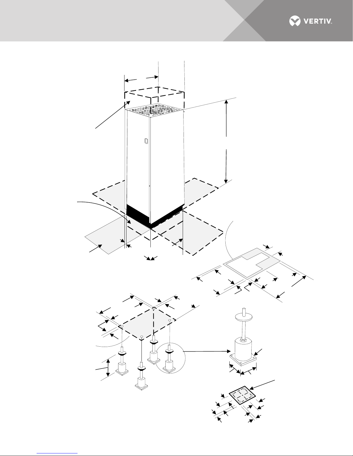
Figure 1 Typical cabinet and floor planning dimensions, sidecar
18"
(457mm)
1-14"
(32mm)
30"
(762mm)
23- 7/8"
(733 mm)
1/2"
(13mm)
Unit Base
Outline
Floor Pedestals
Available from 6"-19"
(152mm to 483mm)
9/16" (14mm)
Dia. Holes
2-1/4"
(57mm)
2-1/4"
(57mm)
2-1/4"
(57mm)
3/4"
(19mm)
3/4"
(19mm)
6"
(152mm)
6" (152mm)
2"
(50mm)
4"
(102mm)
18" (457 mm)
10"
(254 mm)
30" (762mm)
12"
(305 mm)
22"
(559mm)
7"
(178 mm)
20"
(508mm)
Overall
Dimension
18"
(457mm)
Unit Base
Pedestal
Footprint
Shaded areas indic ate
recommended clearance
of 42" (1067mm) at front
and one other side for
service access.
Clearance of 6"
(152mm) below unit is
recommended for
cooling airflow and
cable exit .
Clearance of 18"
(457mm) above unit is
recommended for
cooling airflow .
Cutout area for
cable exit and
cooling airflow .
77"
(1959 mm )
32"
(813 mm)
1"
(25.4mm)
30"
(762 mm)
Unit Base
Optional Floor
Pedestals
Footprint and Floor
Cutout Dimensions
Cabinet Dimensions
The Liebert EXC weighs 300 lb. (136kg)
Vertiv | Liebert® PPC™ User Manual | Rev. 6 | 03/18 | 3
Page 8
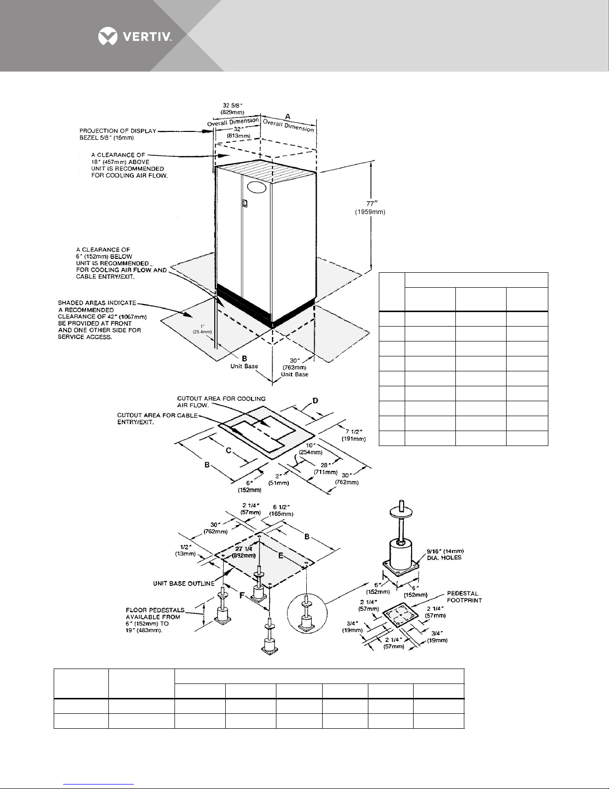
Figure 2 Typical cabinet and floor planning dimension data
Unit
kVA
Weight, lb. (kg)
60 Hz 50 Hz
Without
Xfmr
15 650 (295) 700 (318) 400 (182)
30 750 (340) 800 (363) 400 (182)
50 898 (408) 925 (420) 400 (182)
75 1115 (507) 1150 (522) 400 (182)
100 1275 (579) 1400 (635) 450 (204)
125 1450 (658) 1575 (715) 450 (204)
150 1789 (813) 1900 (862) 700 (318)
200 2110 (959) 2300 (1043) 700 (318)
225 2353 (1070) 2450 (1111) 700 (318)
Add 50 lb. (14kg) to 50 thru 125 kVA units in 44"
cabinet.
CABINET DIMENSIONS
Footprint and Floor
Cutout Dimensions
Optional Floor
Pedestals
Unit kVA
No. of
Panelboards
ABCDEF
Dimensions, in. (mm)
15 to 125 1 32 (813) 30 (762) 18 (457) 15 (381) 17 (432) 29 (737)
150 to 225 2 44 (1118) 42 (1067) 30 (762) 27 (686) 29 (737) 41 (1041)
Vertiv | Liebert® PPC™ User Manual | Rev. 6 | 03/18 | 4
Page 9
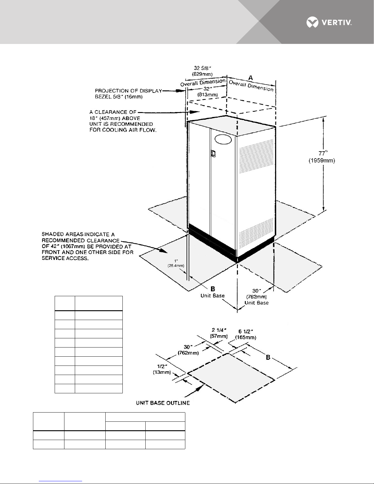
Figure 3 Typical cabinet and floor planning dimension data, top exit unit
Footprint Dimensions
CABINET DIMENSIONS
Unit
kVA Weight, lb. (kg)
15 650 (295)
30 750 (340)
50 950 (432)
75 1165 (530)
100 1325 (601)
125 1500 (680)
150 1789 (813)
200 2110 (959)
225 2353 (1070)
Unit kVA
15-125 1 32 (813) 30 (762)
150-225 1 44 (1118) 42 (1067)
Vertiv | Liebert® PPC™ User Manual | Rev. 6 | 03/18 | 5
No. of
Panelboards
Dimensions, in. (mm)
AB
Page 10

1.1.3 Unit Preparation
The Liebert PPC may be removed from the shipping pallet and installed by customer personnel. A typical
procedure is:
1. Set the palletized assembly in a level area, where there is enough room to roll the unit and entire cable assembly off the
pallet onto the floor.
2. Cut the shipping bands.
WARNING
Risk of cutting bands under tension. Can cause injury or death.
The shipping bands may be under tension. Use appropriate eye, face and hand protection to safeguard
against injury from band backlash.
3. Remove the factory-provided ramp from its shipping position—packed in front of the unit. Place the ramp adjacent to the
pallet to provide a smooth path from pallet to floor.
4. Remove side and rear panels from the module. An Allen wrench for the side panels is furnished in the installation packet.
(Carefully disconnect panel ground wires by pulling the easy-disconnect terminals at the unit frame.)
5. Remove the bolts holding the unit to the shipping pallet. (Located in each of the four bottom corners.)
6. Remove shipping blocks from under unit, then remove chocks from all casters.
7. Roll unit off pallet onto floor.
8. Roll unit to its installation location. For units located on a raised floor, use care when positioning unit over the floor cutout
to avoid casters falling through the cutout.
NOTE
Before maneuvering the unit into its final position, read and follow all advisories in the following paragraphs in
1.1.4 - Location Considerations.
1.1.4 Location Considerations
The Liebert PPC should be located within the computer room, and/or close to the load(s) which it is supplying.
Equipment Location—Should employ the shortest output distribution cable runs consistent with logical
equipment arrangement and allowances for future additions.
Operating Environment—Ambient temperatures of 32°F to 104°F (0°C to 40°C) with a relative humidity of 0%
to 95% (non-condensing).
Bottom Clearance—Required for exit of cables/conduit and/or for cooling air flow. This clearance is
automatically provided by a raised floor (6 in. / 150 mm minimum height). Figures 1 and 2 show typical
raised-floor cutout dimensions.
When units are not located on a raised floor (or if the raised floor is not adequate to support the unit), optional
floor pedestals may be used. (Non-raised floor applications are not CSA approved.) Units with top cable exit
provisions and side vents do not require bottom clearance.
Recommended Minimum Service Clearances—Shown in Figure 4. The indicated clearances at the front and
one other side or rear of the unit are required for service access by the National Electrical Code (NEC)
(Article 110-26). Clearance above the unit is required for cooling air flow (exhaust).
Heat Output—As do all electrical devices, the Liebert PPC produces heat under normal operation. (See Table 1.)
This heat output should be included when calculating the environmental conditions of the room.
Vertiv | Liebert® PPC™ User Manual | Rev. 6 | 03/18 | 6
Page 11
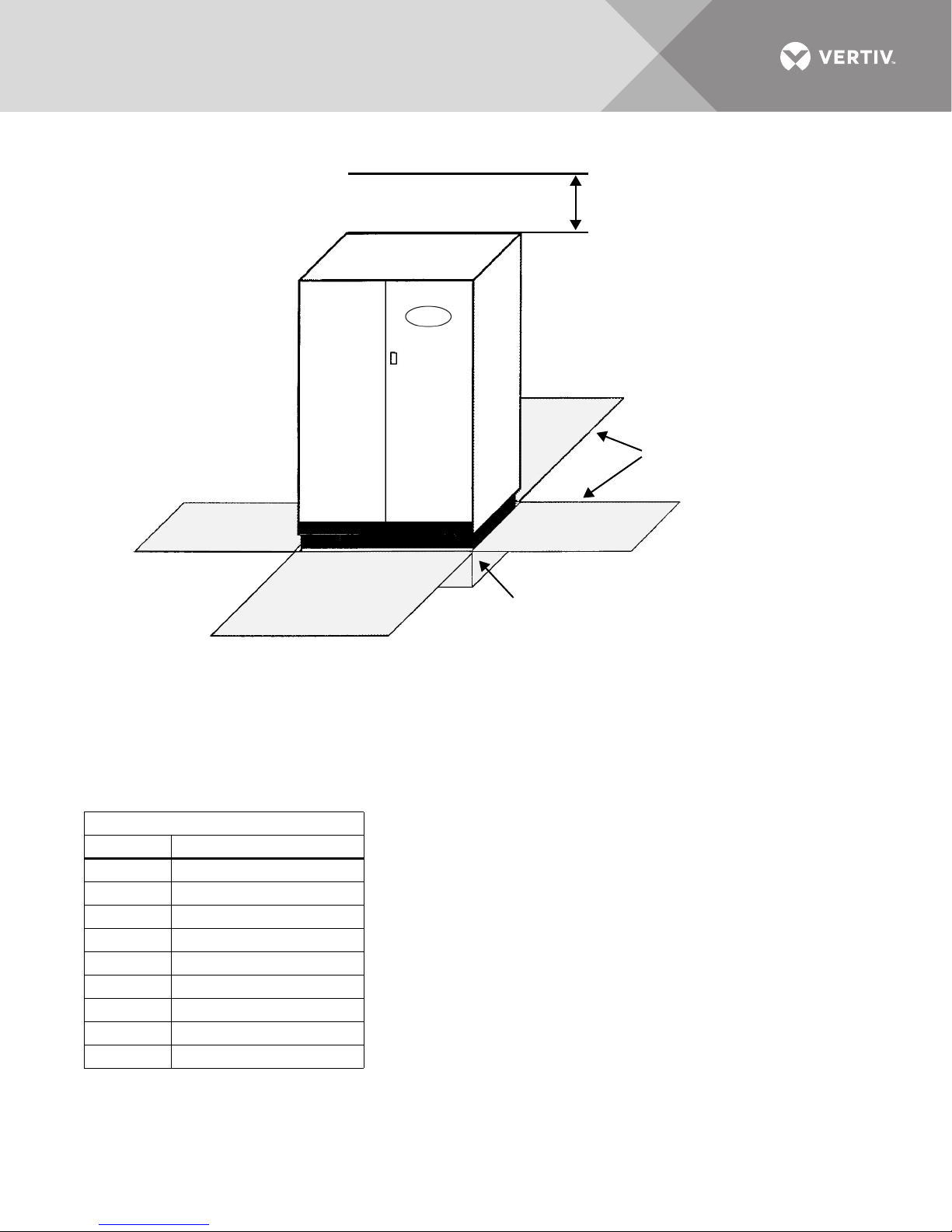
Figure 4 Recommended minimum service and ventilation clearances
18 in. (457mm)
minimum clearance
above unit for
cooling air flow
ADDITIONAL ACCESS ON EITHER
SIDE OR THE REAR OF UNIT - see
Notes 1 and 2
6 in. (152 mm) minimum
clearance below unit for
bottom cable exit
NOTES:
1. Service access is required at the front, plus one other side or rear.
2. Service access clearance:
36 in. (914 mm) for units up to 150 volts to ground
42 in. (1067 mm) for units over 150 volts to ground
FRONT ACCESS REQUIRED
See Notes 1 and 2
See Note 2
See Note 2 See Note 2
Table 1 Heat output
Full Load Heat Output, BTU/hr (kW)
kVA BTU/hr (kW)
15 1915 (0.56)
30 3995 (0.88)
50 4360 (1.28)
75 6140 (1.80)
100 7680 (2.25)
125 9460 (2.77)
150 10,660 (3.13)
200 13,930 (4.08)
225 15,350 (4.45)
Vertiv | Liebert® PPC™ User Manual | Rev. 6 | 03/18 | 7
Page 12
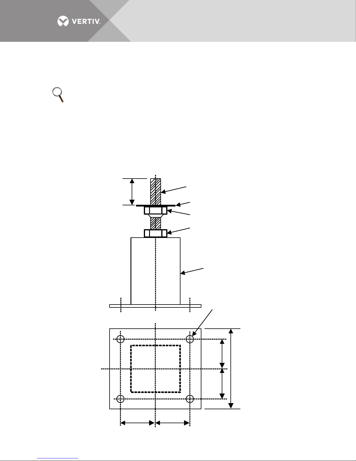
1.1.5 Floor Pedestal Installation
6"
(152mm)
square
2-1/4"
(57mm)
2-1/4"
(57mm)
2-1/4"
(57mm)
2-1/4"
(57mm)
9/16 " (14mm)
diam eter
mounting holes
Pedestal
Base
Jam Nut
Welded Nut
Washer
Threaded
Shaft
3"
(76mm)
Floor pedestals are optional equipment intended to provide clearance for bottom cable entry without relying on
a raised floor to support the unit. The pedestals are adjustable over approximately 3-1/2 in. (89mm) to allow
leveling the unit and minor adjustments in the unit’s installed height.
NOTE
Floor pedestals may be reverse-assembled for shipping. Before installation, reassemble the pedestals as shown
in Figure 5. When the pedestal is properly assembled, the washer on top of the welded nut provides a bearing
surface for the unit’s weight.
1. Insert the pedestal threaded shaft into the inside corner tubing of the cabinet base as shown in Figures 1 and 2.
2. Adjust the pedestal height by turning the welded nut/shaft assembly into or out of the pedestal base as required.
3. Lock the height by tightening the jam nut against the pedestal base.
The pedestal may be secured to the floor by means of the four holes in the base. Locations of floor pedestals are
shown in Figures 1 and 2.
Figure 5 Floor pedestal details
Vertiv | Liebert® PPC™ User Manual | Rev. 6 | 03/18 | 8
Page 13

1.2 Distribution Sidecar Mounting and Wiring
For Liebert PPC units with more than two panelboards, the additional panelboards are furnished in side-mounted
enclosures that are shipped separate from the main unit.
1.2.1 Sidecar Mounting
The additional distribution sidecar is 18 in. x 30 in. (457x762mm) and can be mounted on either the left or right
side of the main unit, with left side mounting recommended.
1. Provide a floor cutout for exit of output cables, as shown in Figure 1.
2. Remove the side panel, the upper panel retainers and the lower panel hooks from the main unit.
3. Align the distribution sidecar with the main unit and bolt the two frames together using the four bolts and hardware
provided.
4. If floor pedestals are used for the main unit, two additional floor pedestals are required for the outside corners of the
sidecar. See Figure 1.
5. Install the upper panel retainers and lower panel hooks on the sidecar enclosure.
6. After electrical connections are completed, install the unit side panel on the sidecar.
1.2.2 Sidecar Electrical Connections
Five conductors (3-phase conductors, neutral and ground) are furnished with the distribution sidecar for
connection to the main unit in the field, along with an intercabinet frame ground conductor.
For Liebert PPC’s with transformers, the sidecar phase conductors are connected directly to the transformer
terminals:
• Phase A (wire 412) to X1
• Phase B (wire 422) to X2
• Phase C (wire 432) to X3
The sidecar neutral (Wire 442) and ground (Wire 452) conductors are connected to the Liebert PPC main
ground busbar (see unit wiring diagram).
For Liebert PPC’s without transformers, the sidecar phase and neutral conductors are connected to the
corresponding output power distribution terminal blocks inside the main unit. The sidecar ground conductor is
connected to the main ground busbar.
For all Liebert PPC’s with VPMP monitoring, route each sidecar conductor through the appropriate current
transformer (CT) in the main unit.
NOTE
Sidecar conductors must pass through the current transformers in the same direction as the main unit
panelboard conductors. Use the existing main unit panelboard wiring for reference.
1.3 Power and Control Wiring
Power and control wiring should be installed by licensed electricians. All power and control wiring must comply
with the NEC and applicable local codes.
Vertiv | Liebert® PPC™ User Manual | Rev. 6 | 03/18 | 9
Page 14

1.3.1 Input Power Connections
If the unit is furnished with junction boxes, input power connections are made as detailed in 1.3.2 - Junction Box
Installation (If Used).
If junction boxes are not furnished, the input power feeder is connected to the input power lugs or blocks located
inside the unit. (See Figures 6, 8, and 10.)
WARNING
Risk of electric shock. Can cause injury or death.
Verify that all incoming line voltage (power) and low-voltage (control) circuits are de-energized and
locked out before installing cables or making connections, whether in the junction box or in the unit.
To minimize disturbances caused by other loads in the building, the 3-phase power input to the unit should be
supplied directly from the service entrance or other power source (a dedicated power feeder).
The input feeder circuit should be sized in accordance with the NEC and any local building codes to assure the
feeder’s ability to safely carry the system’s full load current, including losses.
Input feeder conductors should be sized for no more than 2% voltage drop. If operation at undervoltage
conditions for extended periods of time is desired, the input feeders must be oversized.
Typical conductor size data is shown in Ta bl e 2. All connections must comply with the NEC and all other
applicable codes.
For units with a transformer, the main input feeder should consist of 3-phase conductors and one (safety)
ground conductor (3W + G).
For units without a transformer, the main input feeder must consist of 3-phase conductors, one neutral and
one (safety) ground conductor (4W + G).
Vertiv | Liebert® PPC™ User Manual | Rev. 6 | 03/18 | 10
Page 15
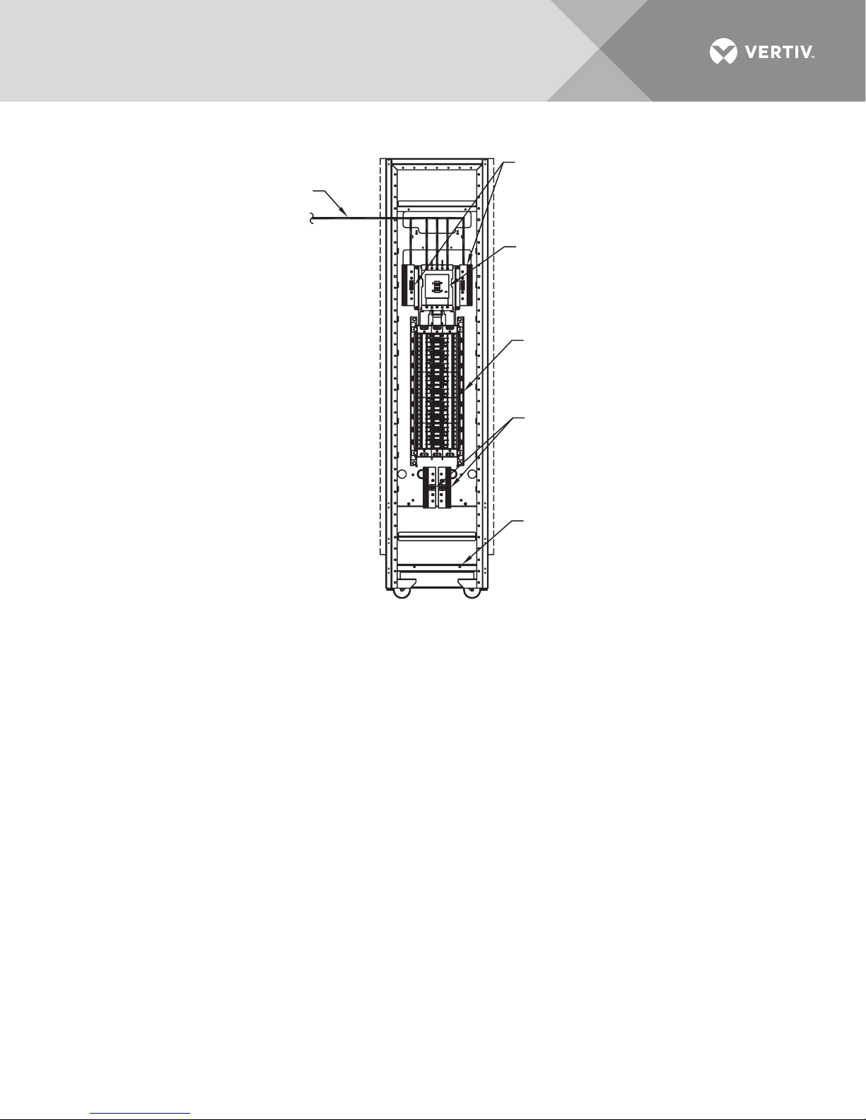
Figure 6 Electrical connection locations, sidecar unit
Interconnection Wiring
provided by factory
Neutral Connections
Distribution Cables Neutral(s)
connected to distribution
panelboard neutral busbar
Panelboard Main Circuit Breaker
Factory-Wired
NOTES
1. The unit bolts to the main
Liebert Precision Power Center. See
installation manual for instructions.
2. Site panel is taken from the Liebert PPC
and installed to either the left or right side
of the unit.
FRONT VIEW WITH DOOR OPEN
AND PANEL REMOVED
Distribution Panelboard
Ground Connections
Distribution Cable Ground(s)
connected to distribution
panelboard ground busbar
Distribution Cable Conduit Connection
Cable Tray 1-3/32" (27.8mm) holes for
3/4" conduit fittings and 7/8" (22.2mm)
holes for 1/2" conduit fittings provided for
securing optional distribution cables
PPC15010
Rev. 2
Vertiv | Liebert® PPC™ User Manual | Rev. 6 | 03/18 | 11
Page 16
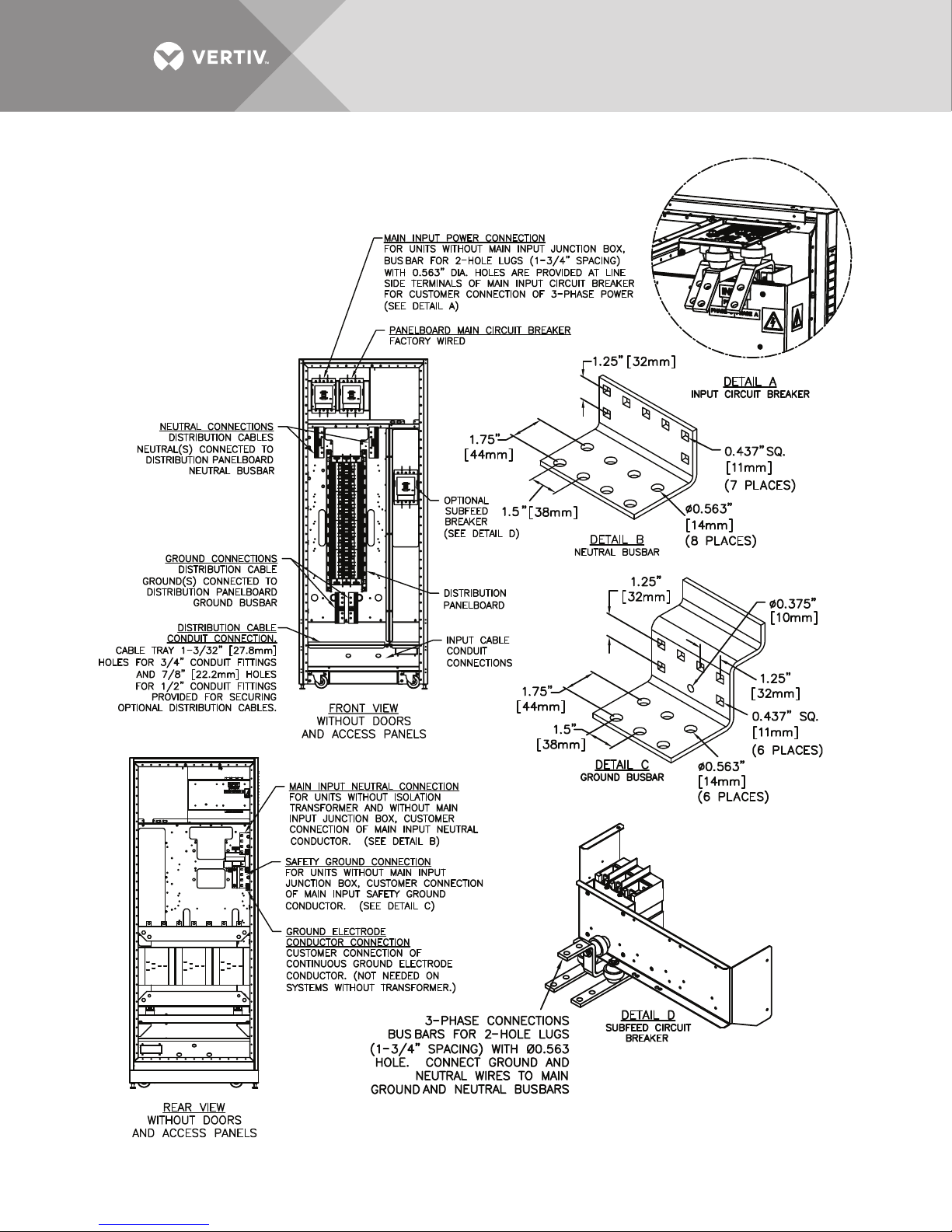
Figure 7 Electrical connection location for 72-pole Square D or 54-pole GE panelboards, 32" cabinet, bottom entry/exit
Vertiv | Liebert® PPC™ User Manual | Rev. 6 | 03/18 | 12
PPC15100
Rev. 0
Page 17
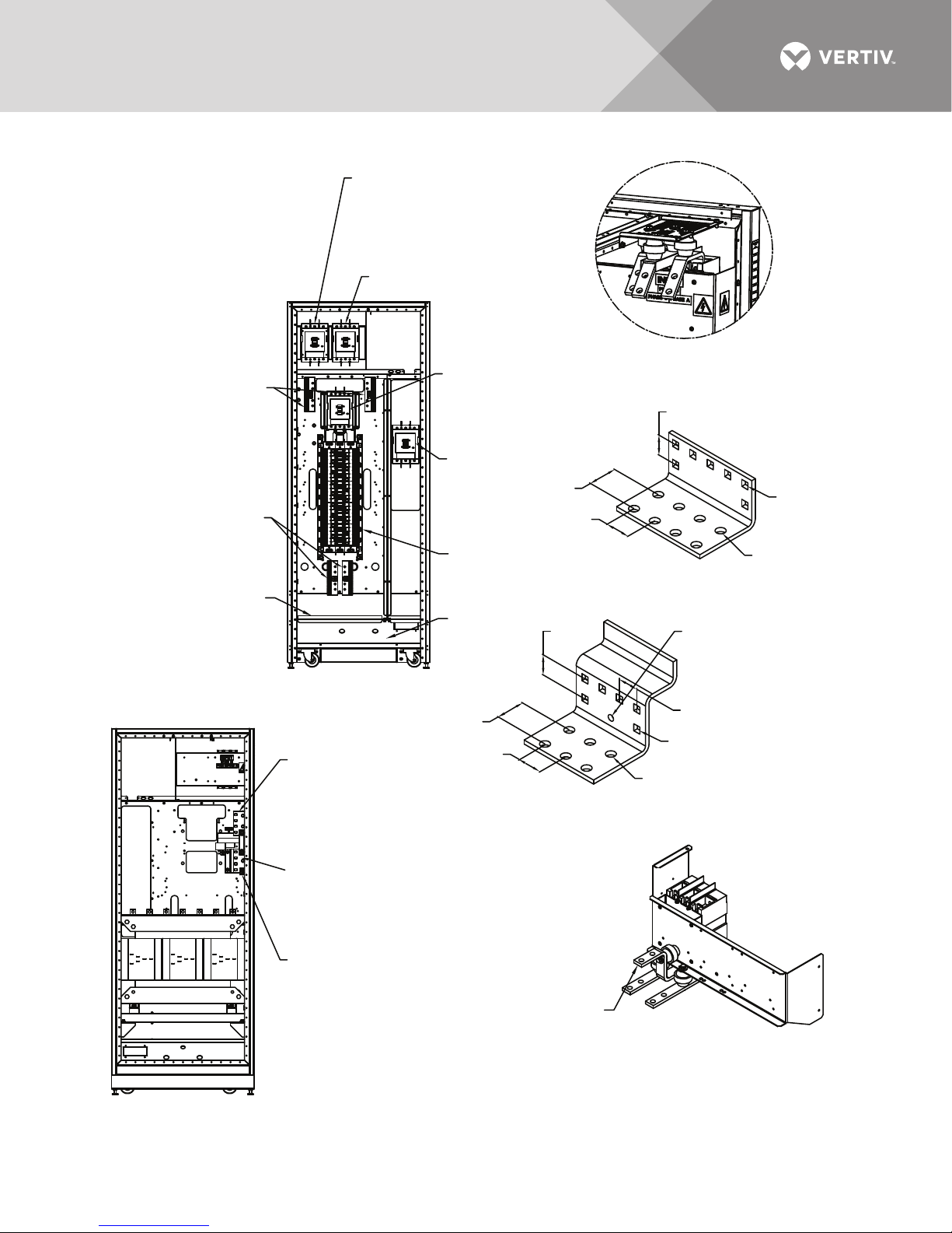
Figure 8 Electrical connection locations, for 54-pole Square D or 42-pole GE panelboard, 32" cabinet, bottom entry/exit
Main Input Power Connection
For units without main input junction box.
Busbars for 2 hole lugs (1 3/4" spacing)
with 0.563" dia. holes are provided at line
side terminals of main input circuit breaker
for customer connection of 3-phase power
(See Detail A)
Optional Subfeed Breaker
(See Detail D)
Neutral Connections
Distribution Cables
Neutral(s) connected
to distribution panelboard
neutral busbar
Ground Connections
Distribution Cables
Ground(s) connected
to distribution panelboard
ground busbar
Distribution Cable
Conduit Connection
Cable tray 1-3/32" (27.8mm)
holes for 3/4" conduit fittings
and 7/8" (22.2mm) holes
for 1/2" conduit fittings
provided for securing
optional distribution cables.
Front View
Without Doors
Main Input Neutral Connection
For units without isolation
transformer and without main
input junction box, customer
connection of main input neutral
conductor. (See Detail B)
Panelboard Main
Circuit Breaker
Factory-Wired
Optional Subfeed
Breaker
(See Detail D)
Distribution
Panelboard
Input Cable
Conduit
Connections
1.75"
(44mm)
1.50"
(38mm)
1.74"
(44mm)
1.50"
(38mm)
1.25"
(32mm)
Detail C
Ground Busbar
Detail A
Input Circuit Breaker
1.25"
(32mm)
Detail B
Neutral Busbar
ø0.375" (10mm)
1.25"
(32mm)
0.437" sq. (11mm)
(6 Places)
ø0.563" (14mm)
(6
Places)
sq.
0.437"
(11mm)
(7 Places)
ø0.563" (14mm)
(8 PLACES)
Safety Ground Connection
For units without main input
junction box, customer connection
of main input safety ground
conductor. (See Detail C)
Ground Electrode
Conductor Connection
Customer connection of
continuous ground electrode
conductor. Not needed on
systems without transformer.
Rear View
Without Doors
Vertiv | Liebert® PPC™ User Manual | Rev. 6 | 03/18 | 13
3-phase Connections
Busbars for 2-hole lugs
(1-3/4" spacing) with ø0.563
hole. Connect ground and
neutral wires to main ground
and neutral busbars
Detail D
Subfeed Circuit Breaker
PPC15101
Rev. 0
Page 18
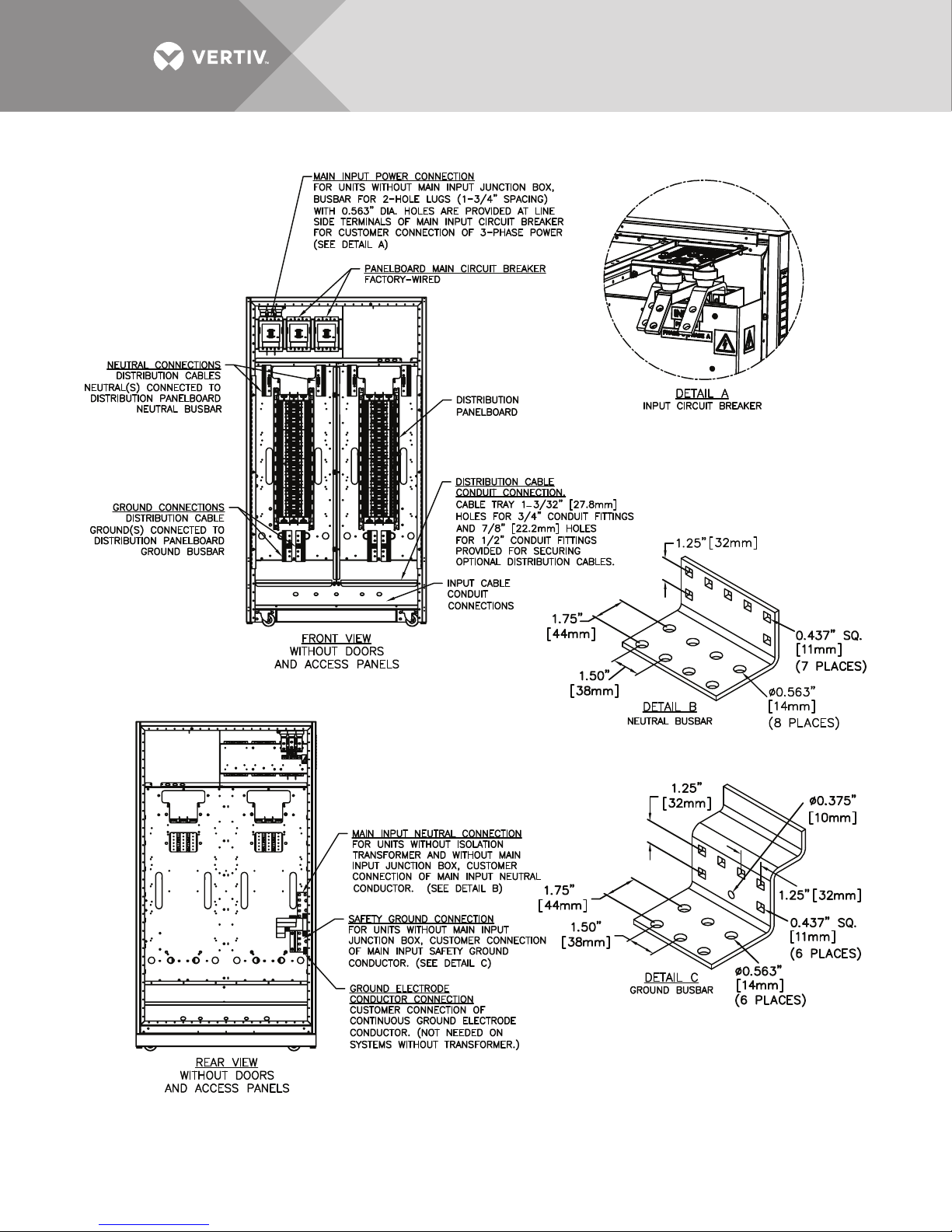
Figure 9 Electrical connection location for 72-pole Square D or 54-pole GE panelboard, 44" cabinet, bottom entry/exit
PPC15102
Rev. 0
Vertiv | Liebert® PPC™ User Manual | Rev. 6 | 03/18 | 14
Page 19
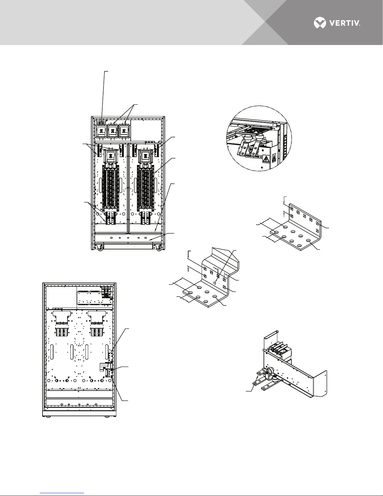
Figure 10 Electrical connection locations, 54-pole Square D or 42-pole GE panelboard, 44" cabinet, bottom entry/exit
Main Input Power Connection
For units without main input junction box, busbar
for 2-hole lugs (1 3/4" spacing) with 0.563" dia. holes
are provided at line side terminals of main input circuit breaker
for customer connection of 3-phase power (See Detail A)
Subfeed Circuit Breakers (Optional
(See Detail B)
Panelboard Main
Neutral Connections
Distribution cables
neutral(s) connected to
distribution panelboard
neutral busbar.
Ground Connections
Distribution cable
ground(s) connected to
distribution panelboard
ground busbar.
FRONT VIEW
Without Doors and Access Panels
Circuit Breaker
Factory-Wired
Distribution
Panelboard
Distribution Cable
Conduit Connection
Cable Tray 1-3/32" (27.8mm)
Holes for 3/4" conduit fittings
and 7/8" (22.2mm) holes
for 1/2" conduit fittings
provided for securing
optional distribution cables
.
Input Cable
Conduit Connections
1.25"
(32mm)
DETAIL A
Input Circuit Breaker
1.75"
(44mm)
1.50"
(38mm)
ø0.375"
(10mm)
Neutral Busbar
1.25"
(32mm)
DETAIL B
ø0.563"
(14mm)
(8 Places)
0.437" sq.
(11mm)
(7 Places)
Without Doors and Access Panels
REAR VIEW
1.75"
(44mm)
1.50"
(38mm)
DETAIL C
Ground Busbar
Main Input Neutral Connection
For units without isolation
transformer and without main
input junction box, customer
connection of main input neutral
conductor. (See Detail B).
Safety Ground Connection
For units without main input
junction box, customer connection
of main input safety ground
conductor. (See Detail C).
Ground Electrode
Conductor Connection
Customer connection of
continuous ground electrode
conductor. Not needed on
systems without transformer.
1.25"
(32mm)
0.437" SQ. (11mm)
(6 Places)
ø0.563" (14mm)
(6 Places)
3-Phase Connections
Busbars for 2-hole lugs
(1 3/4" spacing) with ø0.563"
hole. connect ground and
neutral wires to main ground
and neutral busbars.
DETAIL D
Subfeed Circuit Breaker
PPC15103
Rev. 0
Vertiv | Liebert® PPC™ User Manual | Rev. 6 | 03/18 | 15
Page 20
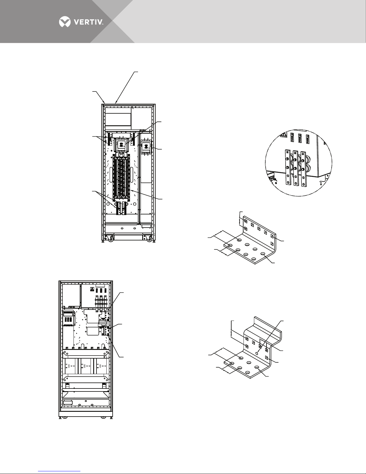
Figure 11 Electrical connection location for 54-pole Square D or 42-pole GE panelboard, 32" cabinet, top entry/exit
Distribution Cable
Conduit Connection
Cable tray 1 3/32" (27.8mm) holes for
Input Cable
Conduit Connections
Neutral Connections
Distribution Cables
Neutral(s) connected
to distribution panelboard
neutral busbar
Ground Connections
Distribution Cables
Ground(s) connected
to distribution panelboard
ground busbar
3/4" conduit fittings and 7/8" (22.2mm)
holes for 1/2" conduit fittings provided
for securing optional distribution cables
Panelboard Main Circuit Breaker
Factory-Wired
Main Input Power Connection
For units without main input junction box,
bus bar for 2 hole lugs (1 3/4" spacing)
with 0.563" dia. holes are provided at line
side terminals of main input circuit breaker
for customer connection of 3-phase power
(See Detail A)
Distribution Panelboard
1.25"
(32mm)
Detail A
Input Circuit Breaker
Front View
Without Doors and Access Panels
Main Input Neutral Connection
For units without isolation
transformer and without main
input junction box, customer
connection of main input neutral
conductor. (See Detail B)
Safety Ground Connection
For units without main input
junction box, customer connection
of main input safety ground
conductor. (See Detail C)
Ground Electrode
Conductor Connection
Customer connection of
continuous ground electrode
conductor. Not needed on
systems without transformer.
1.75"
(44mm)
1.50"
(38mm)
1.75"
(44mm)
(38mm)
1.50"
Detail B
Neutral Busbar
1.25"
(32mm)
Detail C
Ground Busbar
0.437" sq.
(11mm)
(7 places)
ø0.563"
(14mm)
(8 places)
ø0.375"
(10mm)
1.25" (32mm)
0.437" sq.
(11mm)
(6 places)
ø0.563"
(14mm)
(6 places)
Rear View
Without Doors and Access Panels
Vertiv | Liebert® PPC™ User Manual | Rev. 6 | 03/18 | 16
PPC15121
Rev. 0
Page 21
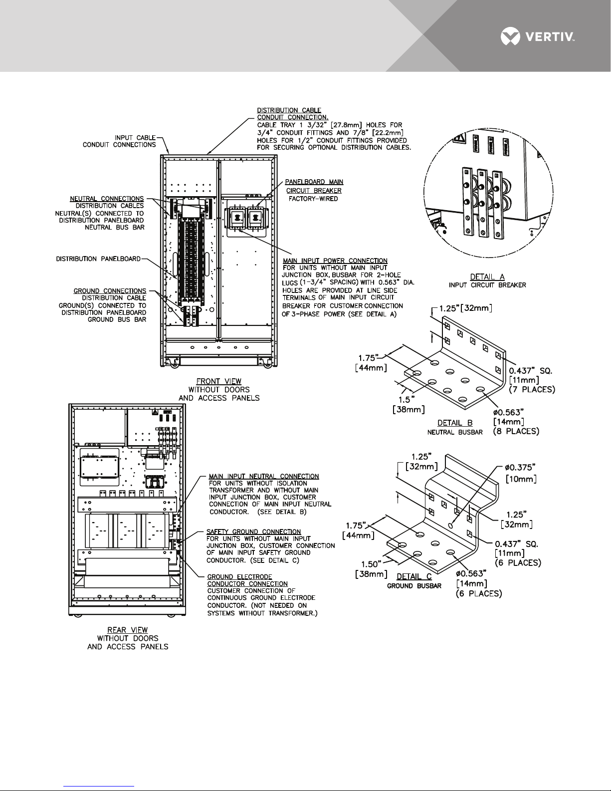
Figure 12 Electrical connection location for 72-pole Square D or 54-pole GE panelboard, 44" cabinet, top entry/exit
PPC15122
Rev. 0
Vertiv | Liebert® PPC™ User Manual | Rev. 6 | 03/18 | 17
Page 22

Table 2 Suggested minimum input wire size data
Units with Transformers Transformerless Units
Input
Vol tage kVA
15 43 60 6 42 60 6
30871062 831062
50 145 200 000 139 175 00
208V
240V
380V
400V
415V
75 215 295 350 kcmil 208 295 350 kcmil
100 286 400 (2) 000* 277 350 (2) 00*
125 358 432 (2) 0000* 347 432 (2) 0000*
150 427 600 (2) 350 kcmil* 416 600 (2) 350 kcmil*
15 38 50 8
30 75 100 2
50 125 170 00
75 186 250 250 kcmil
100 248 340 (2) 00*
125 310 400 (2) 000*
150 370 480 (2) 250 kcmil*
15 24 30 10 23 30 10
30 47 59 6 46 59 6
50 79 100 2 76 100 3
75 117 150 0 114 150 0
100 157 200 000 152 200 000
125 196 250 0000 190 250 250 kcmil
150 234 295 350 kcmil 228 295 350 kcmil
200 312 400 (2) 000* 304 400 (2) 000*
225 351 432 (2) 0000* 342 432 (2) 0000*
15 23 30 10 23 30 10
304559643596
50 75 100 2 72 90 2
75 112 150 0 108 150 0
100 149 200 000 144 200 000
125 186 250 250 kcmil 180 225 0000
150 223 295 350 kcmil 217 295 350 kcmil
200297400(2) 000*289400(2) 000*
225 334 432 (2) 0000* 325 432 (2) 0000*
15 22 30 10 21 30 10
304359642596
50 72 100 2 70 100 3
75 108 150 0 104 150 0
100 143 200 000 139 175 00
125 179 225 0000 174 225 0000
150 214 295 350 kcmil 209 295 350 kcmil
200 285 400 (2) 000* 278 350 (2) 00*
225 321 432 (2) 0000* 313 432 (2) 000*
Input
FLA
Input
OPD
Suggested Feeder
Wire Size (AWG)
Input
FLA
—— —
Input
OPD
Suggested Feeder
Wire Size (AWG)
Vertiv | Liebert® PPC™ User Manual | Rev. 6 | 03/18 | 18
Page 23
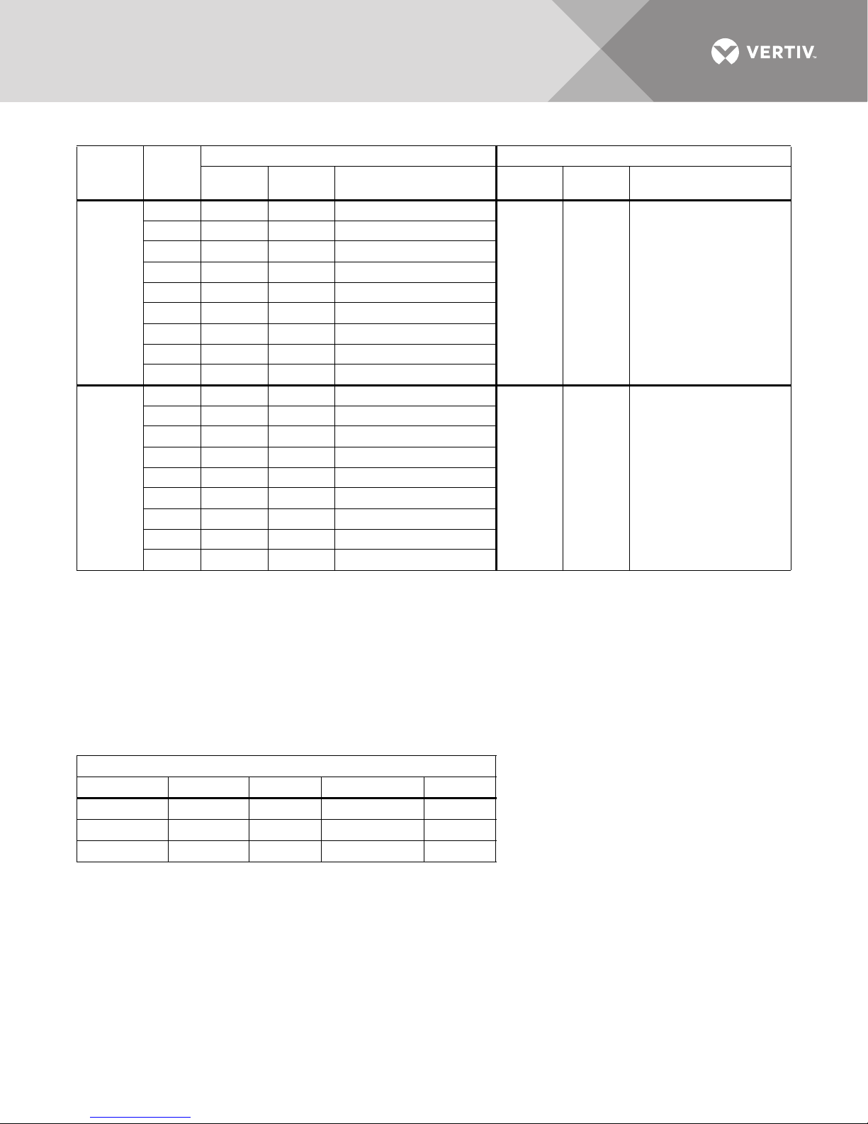
Table 2 Suggested minimum input wire size data (continued)
Units with Transformers Transformerless Units
Input
Vol tage kVA
15 19 14 10
30 38 50 8
50 63 80 4
75 93 125 1
480V
100 124 170 00
125 155 200 000
150 185 250 250 kcmil
200 247 340 (2) 00*
225 278 340 (2) 00*
15 15 20 12
30 30 40 8
50 50 68 4
75 74 100 2
600V
100 99 125 1
125 124 170 00
150 148 200 000
200 197 250 250 kcmil
225 222 295 350 kcmil
* Parallel feeders per NEC 300-20 and 310-4.
FLA = Full Load Amps of Liebert PPC
OPD = Overcurrent Protection Device inside Liebert PPC
Wire Sizes based on NEC Table 310-16, using 75°C copper conductor.
NOTES:
1. Main input power feeder should be a dedicated feeder direct from service entrance or other power source, if possible.
2. Ground conductors recommended to be insulated conductors run with power conductors for increased system performance. Ground conductor minimum
size per NEC Table 250-95. Input power feeder conduit may be used as the safety ground conductor. When conduit is used, adequate electrical continuity
must be maintained at conduit connections to enclosures and throughout conduit run.
3. Input feeder wire size listed in this table is the minimum feeder size recommended. Larger wire size may be required because of voltage drop or supply
overcurrent protection device.
4. For transformerless units with 3-phase 4W + G input feeder, larger wire size may be required because of excessive neutral current (see NEC Table 310-16
Notes 8 and 10). For best performance, the unit should be located as close to the load as practical.
Input
FLA
Input
OPD
Suggested Feeder
Wire Size (AWG)
Input
FLA
Input
OPD
Suggested Feeder
Wire Size (AWG)
—— —
—— —
Table 3 Main input circuit breaker interrupting rating
Standard Interrupting Rating*
Unit kVA 208V 480V 380-415V 600V
15-100 100 kA 35 kA 35 kA 25 kA
125-150 100 kA 65 kA 65 kA 50 kA
200-225 — 65 kA 65 kA 50 kA
* Refer to unit specification sheet for units equipped with non-standard main input breakers.
Vertiv | Liebert® PPC™ User Manual | Rev. 6 | 03/18 | 19
Page 24
1.3.2 Junction Box Installation (If Used)
Main input (power) and low-voltage (control) junction boxes are available for the Liebert PPC to simplify
customer connections.
Shipping Arrangements—The junction boxes, if used, can either be shipped with the system or can be
advance-shipped for installation during the roughing-in stage of new construction.
Installation Location—Liebert supplies flexible, 10-foot-long (3 m) cables for connecting the junction boxes to
the unit. The junction boxes should be installed a maximum of 8 ft. (2.4m) from the feeder entrance of the unit.
Vertiv recommends centering the junction boxes under an easily removable floor tile.
Junction Box Connections must be installed in compliance with the NEC and all other applicable codes.
WARNING
Risk of electric shock. Can cause injury or death.
Verify that incoming line voltage (power) and low-voltage (control) circuits are de-energized and locked
out before installing cables or making any connections in the junction box.
Typical junction box connections are shown in Figure 13 and described in 1.3 - Power and Control Wiring.
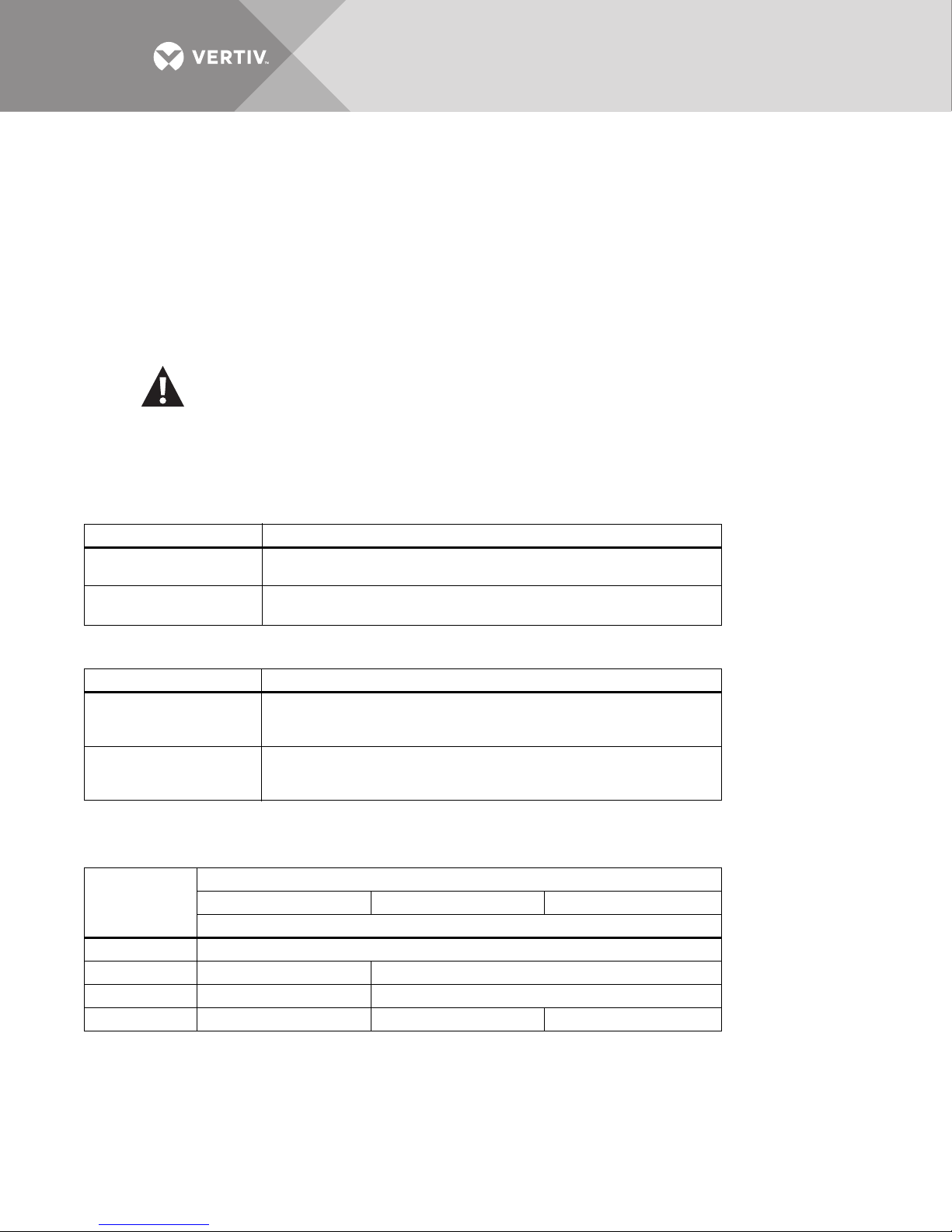
Table 4 Main input junction box with transformer electrical connections
Junction Box Size, In. (mm) Electrical Connections
27 x 14 x 6
(686 x 356 x 152)
35 x 22 x 6
(889 x 559 x 152)
400A, 3-Pole Power Block with 1/2 -13 studs on 1-3/4" (44mm) Centers
750A Ground Busbar with Two Sets of 3/8 - 16 Studs on 1-3/4" (44mm) Centers
750A Phase Busbars with 1/2 -13 Studs on 1-3/4" (44mm) Centers
750A Ground Busbar with Two Sets of 3/8 - 16 Studs on 1-3/4" (44mm) Centers
Table 5 Main input junction box without transformer electrical connections (5 wire)
Junction Box Size, In. (mm) Electrical Connections
27 x 14 x 6
(686 x 356 x 152)
35 x 22 x 6
(889 x 559 x 152)
400A 3-Pole Power Block with 1/2 -13 Studs on 1-3/4" (44mm) Centers
750A Neutral Busbar with Two Sets of 1/2 - 13 Studs on 1-3/4" (44mm) Centers
750A Ground Busbar with Two Sets of 3/8 - 16 Studs on 1-3/4" (44mm) Centers
750A Phase Busbars with 1/2 -13 Studs on 1.75” Centers
1500A Neutral Busbar with Two Sets of 1/2 - 13 Studs on 1-3/4" (44mm) Centers
750A Ground Busbar with Two Sets of 3/8 - 16 Studs on 1-3/4" (44mm) Centers
Dimensions—Dimensions are given on the drawings furnished with the unit. Typical box dimensions are:
Table 6 Main input (power) junction box dimensions, typical
Input Voltage
208-240V 380-415V 480-600V
Unit Rating, kVA
15-100 27 x 14 x 6 (686 x 356 x (152)
125-150 35 x 22 x 6 (889 x 559 x 152) 27 x 14 x 6 (686 x 356 x (152)
200 kVA N/A 27 x 14 x 6 (686 x 356 x (152)
225 kVA N/A 35 x 22 x 6 (889 x 559 x 152) 27 x 14 x 6 (686 x 356 x (152)
Dimensions, L x W x H, inches (mm)
Vertiv | Liebert® PPC™ User Manual | Rev. 6 | 03/18 | 20
Page 25
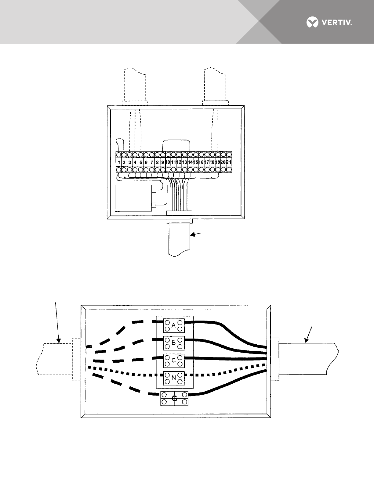
Figure 13 Typical junction box connections
Building
interface
relay
LOW-VOLTAGE CONTROL JUNCTION BOX
MAIN INPUT JUNCTION BOX
Customer input power connection
3 Phase 3W+G for units with transformer
3 Phase 4W+G for units without transformer
Factory-supplied
input cable assembly
Factory-supplied low-voltage
control cable
Vertiv | Liebert® PPC™ User Manual | Rev. 6 | 03/18 | 21
Page 26
1.3.3 System Grounding
The performance and safety of any power conditioning system depend upon proper grounding. Figure 14 shows
the typical grounding arrangements for the Liebert PPC.
Equipment grounding—Grounding is primarily for safety. Correct implementation of grounding also enhances
equipment performance. All power feeders must include equipment grounding means as required by the NEC
and local codes.
An insulated ground conductor is recommended to be run in each feeder conduit. Ground conductors must be
at least the minimum size per NEC Table 250-66. Larger wire sizes may be used for increased system
performance.
If the input power feeder conduit is used as a grounding conductor, adequate electrical continuity must be
maintained at all conduit connections.
WARNING
Risk of electrical shock. Can cause equipment damage, improper operation, injury and death.
Isolating bushings must not be used in a metal conduit run. These busings might prevent the system
from being properly grounded.
Signal reference grid—If the unit is used to supply power to a computer room or area that is equipped with a
signal reference grid or a grounded raised-floor stringer system, a grounding conductor should be connected
from the system ground bus to the grid or floor system. This conductor should be stranded or braided #8 AWG
or larger, and as short as practical. Less than 3 ft. (1 m) is recommended.
1.3.4 Grounding Electrode Conductor (Units With Transformer)
Required by code—The Liebert PPC with transformer must be grounded according to the safety practices of
NEC 250-26. A local grounding electrode conductor is recommended in addition to the equipment safety
ground, which is normally run with the input power conductors.
Unit connection—A terminal is furnished inside the unit for field-connection of the grounding electrode
conductor. (See Figures 6, 8 and 10.)
Electrode connection—As shown in Figure 14, the grounding electrode conductor is run from the unit to the
nearest effectively grounded (in order of preference):
1. Building steel
2. Metal water pipe
3. Other made grounding electrode
Sizing of the grounding electrode conductor is based on the secondary circuit conductors. Ta bl e 7 shows the
minimum recommended grounding electrode conductor according to the NEC.
Table 7 Minimum grounding electrode conductor size (AWG)
Output Voltage
kVA
15888
30888
50 4 8 8
75 2 6 6
100 0 4 4
125 0 2 2
150 00 2 2
200 00 0 0
225 00 0 0
AWG wire size based on 75°C copper conductors
208V 380V 415V
Vertiv | Liebert® PPC™ User Manual | Rev. 6 | 03/18 | 22
Page 27
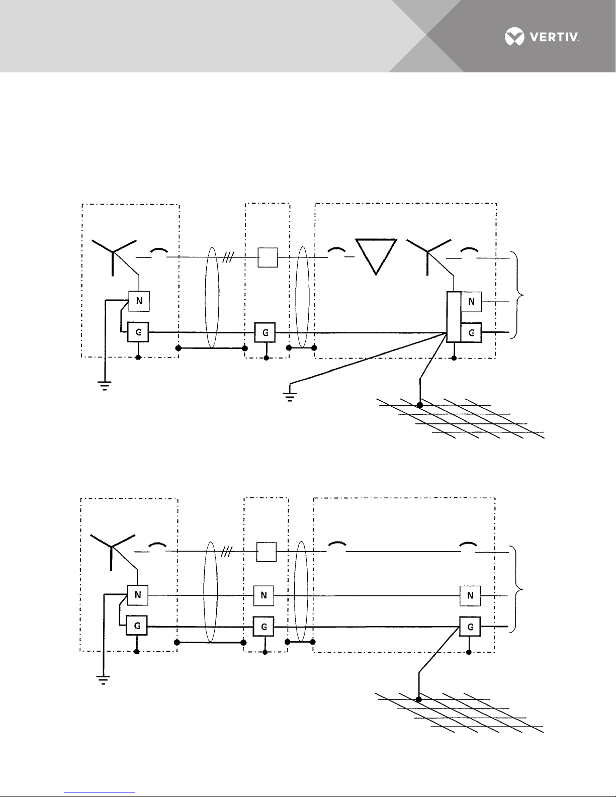
Recommended methods for running the grounding electrode conductor (arranged by preference for system
Local grounding
electrode
conductor per
NEC 250-26
Service
Entrance
Liebert PPC
(without transformer)
Service entrance
grounding electrode
system
Signal reference grid
(if used)
TYPICAL LIEBERT PPC
WITHOUT TRANSFORMER GROUNDING ARRANGEMENT
Input
J-Box
(if used)
TYPICAL LIEBERT PPC
WITH TRANSFORMER GROUNDING ARRANGEMENT
Liebert PPC
(with transformer)
Output
Service
Entrance
Input
J-Box
(if used)
Output
Service entrance
grounding electrode
system
Signal reference grid
(if used)
performance; as permissible by local and other applicable codes):
1. Outside of conduit (where not subject to damage)
2. Inside non-metallic conduit
3. Inside non-ferrous conduit
4. Inside ferrous conduit, bonded to the ferrous conduit at both ends, as acceptable by local and other applicable codes
Figure 14 Typical grounding arrangements
Vertiv | Liebert® PPC™ User Manual | Rev. 6 | 03/18 | 23
Page 28

1.3.5 Output Power Connections
Output circuit breaker(s) and/or panelboards with ground and neutral provisions are provided inside the unit for
connecting load(s) as required. (See Figures 6, 8 and 10.)
Flexible output distribution cables for use in data processing areas under a raised floor are optional and may be
factory supplied. Cable lengths and layout should be well-planned:
• Cable access—Cable routes should follow aisles between equipment. This will facilitate access to cables for installation,
routine inspection, and future changes.
• Cable length—Measure the distance to the load equipment following right-angle paths, rather than diagonally or directly.
Always measure to the extreme far side of the equipment with respect to the unit to insure adequate cable length.
• Air circulation—Prevent restriction of airflow under the raised floor by running the flexible conduits flat on the sub-floor, in
parallel paths.
For best performance, the Liebert PPC should be located as close to the load as practical.
Initial system output loading should be between 50% and 75% of rated capacity. This allows the addition of future
loads without immediately investing in another power conditioner. The high partial-load efficiency of the unit
permits such sizing without imposing an energy-use penalty during initial operation.
Keep the load balanced—Balancing of loads is good design practice on any 3-phase system. Accordingly, each
distribution panel is load-balanced at the factory, based on output branch circuit breaker sizes. All additions to
the system should be arranged so as to preserve this balance.
To ensure proper harmonic current cancellation on phase-shifted, multi-output units, the loads should be
balanced across the multiple outputs as well. For example, with a dual-output unit, the loads should be balanced
across the six output phases. For a quad-output unit, the loads should be balanced across the 12 output phases.
WARNING
Risk of electric shock. Can cause injury or death.
Verify that incoming line voltage circuits are de-energized and locked out before installing output
breakers and cables.
Code compliance—All output cables and connections must comply with the NEC and all other applicable codes.
Padlock-off provisions—All output cables without receptacles that are hard-wired to the load equipment must
be equipped with a padlock-off accessory for the output circuit breaker. The padlock-off accessory is to be used
to lock-out and tag the circuit breaker when service is performed on the hard-wired load equipment in
accordance with OSHA safety rules.
Vertiv | Liebert® PPC™ User Manual | Rev. 6 | 03/18 | 24
Page 29
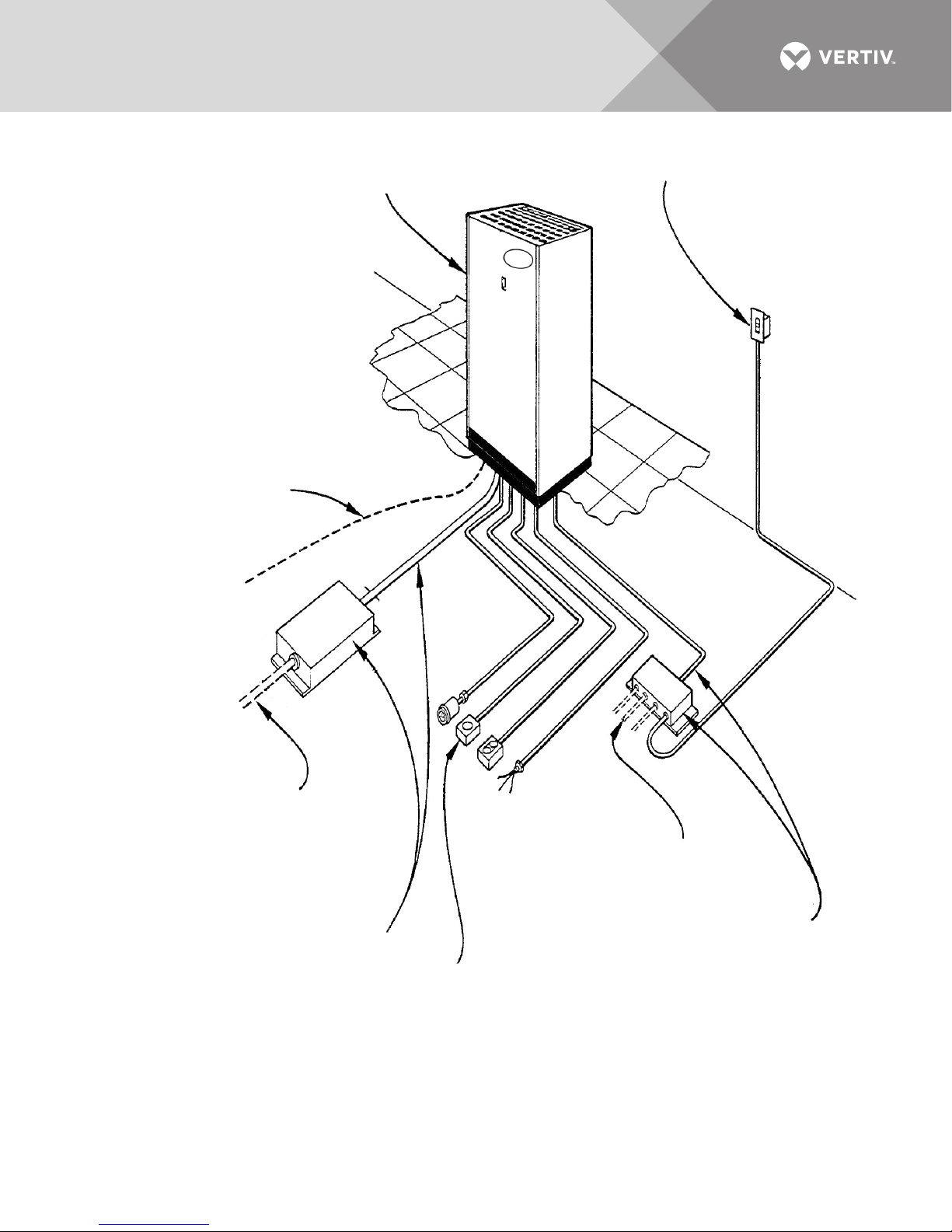
Figure 15 Typical Liebert PPC equipment arrangement
* REPO Switch
Liebert PPC
Ground electrode conductor
(not by Vertiv) required per NEC
for units with transformer
Main input junction box and cable
* Low-voltage junction box
and cable
* Flexible distribution cables
per customer specifications
Building interface and alarm connections
(not by Vertiv)
* Optional devices—refer to the specification sheet for options supplied.
Main input power to unit
(not by Vertiv)
3-phase, 3-wire plus ground
for units with transformer
3-phase, 4-wire plus ground
for units without transformer
Vertiv | Liebert® PPC™ User Manual | Rev. 6 | 03/18 | 25
Page 30
1.3.6 Control Wiring Connections
K5
A
7 4
1
3
69
B
K6
K6K5
+ 24VDC
Overtemp
Switch
5
2
3
1
4
R1
+
-
Liebert PPC
Remote Shutdown
Devices
Main input
breaker
shunt trip
Unit EPO
Building
Interface
Relay
N.O. REPO
N.C. REPO
24 VDC
source
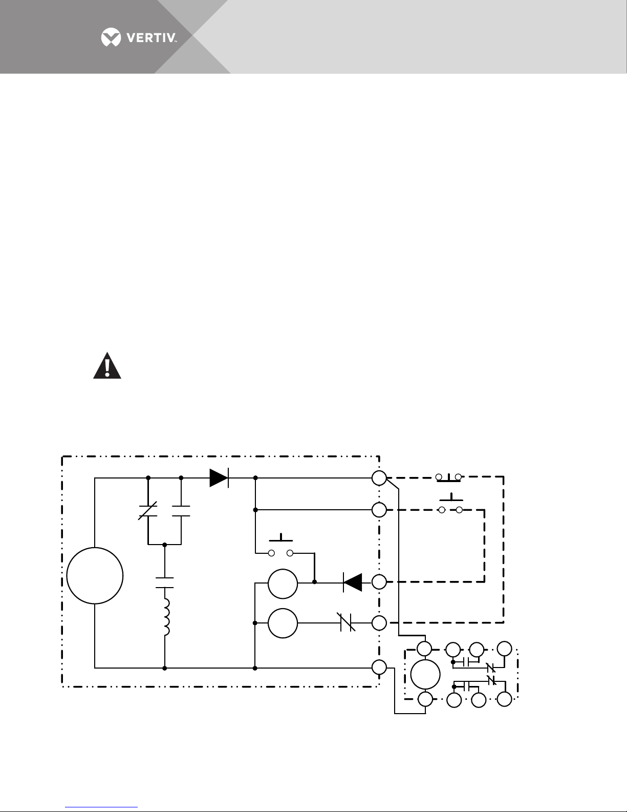
The NEC Article 645 requires that emergency power off (EPO) switches be located at the principal room exits.
All standard Liebert power conditioning systems have provision for external shutdown control from Remote
Emergency Power Off (REPO) stations. Figure 16 is a simplified diagram of the shutdown circuitry of the
Liebert PPC.
Low-voltage control circuit—As shown in Figure 16, the control circuit operates on 24 VDC. The shutdown
device (represented by the REPO switch) activates a low-current 24 VDC relay which in turn operates the
shunt-trip mechanism. The shunt-trip solenoid opens the Main Input Breaker, which de-energizes the
Liebert PPC.
Multiple-unit shutdown—When more than one Liebert PPC is installed by the user, a typical requirement is that
actuation of a single device (REPO, for example) must shut down all Liebert PPC’s. The low-voltage control
circuits of all standard Liebert PPC systems are designed to meet this requirement.
External control wiring connections for remote shutdown, alarm, and/or monitoring are made to the low-voltage
junction box (if used) or to the low-voltage control terminal strip located inside the unit.
Control wiring connections vary with the type of monitoring system furnished with the unit. Two typical control
wiring configurations are shown in Figures 17 and 18.
Code compliance—Control wiring connections must comply with the NEC and all other applicable codes.
WARNING
Risk of electric shock. Can cause injury or death.
Verify that all incoming high-voltage (power) and low-voltage (control) circuits are de-energized and
locked out before installing cables or making connections, whether in the junction box or in the unit.
Figure 16 Simplified shutdown circuit
Vertiv | Liebert® PPC™ User Manual | Rev. 6 | 03/18 | 26
Page 31
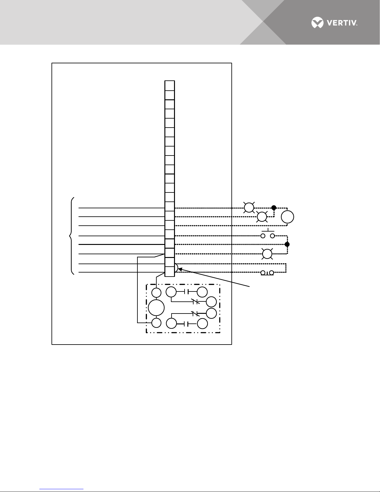
Figure 17 Typical control wiring for units without monitoring
3
69
1
4
7
B
A
R
21
20
19
18
17
16
15
14
13
12
11
10
9
8
7
6
5
4
3
2
1
Overtemp Alarm N .O. W208
Alarm Com. W206
Overtemp Alarm N.O. W207
N.O. REPO W205
+24VDC W204
N.C. REPO W202
REPO Com. W202
+24VDC W 201
BLK
WHT
GRN
Factory-Supplied Wiring
S
Low Voltage
Terminal Strip
Overtemp
Alarm Output
N.O. REPO
N.C. REPO
Remove jumper when
Normally Clos ed
(N.C.) REPO is used
Building
Interface
Relay
NOTES
1. Building Interface Relay can be used for remote shutdown or alarm. Relay is energized during normal operation.
DPDT contacts rated 1/4 HP at 120VAC, 10A at 28VDC or 240VAC.
2. Other N.O. REPO devices may be wired in parallel to the N.O. REPO contacts. Other N.C. REPO devices may be wired
in series to the N.C. REPO contacts. Multiple REPO lamps and other 24VDC loads may be wired in parallel to the
REPO lamps. Maximum 24VDC supply available is 1 Amp total. Both N.O. and N.C. REPO switches are powered from
the same supply.
3. All auxiliary control devices and cabling to be field-supplied except as noted.
4. Overtemperature alarm contacts change state when unit overtemperature is sensed.
Vertiv | Liebert® PPC™ User Manual | Rev. 6 | 03/18 | 27
Page 32
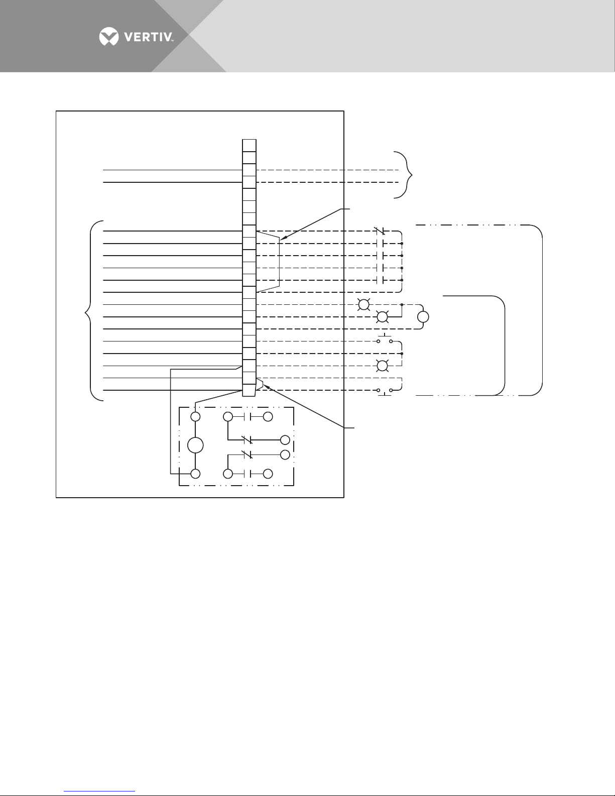
Figure 18 Typical control wiring for units with power monitoring
21
20
19
18
17
16
15
14
13
12
11
10
9
8
7
6
5
4
3
2
1
S
BLK
WHT
GRN
R
A
B
7
9
4
6
1
3
Factory-Supplied Wiring
LOW-VOLTAGE TERMINAL STRIP
Building
Interface
Relay
5TH Customer Alarm W214
4TH Customer Alarm W213
3RD Customer Alarm W212
2ND Customer Alarm W211
1ST Customer Alarm W210
Customer Alarm W209
Summary Alarm N.O. W208
Summary Alarm N.C. W207
Summary Alarm COM. W206
N.O. REPO W205
+24 VDC W204
REPO COM. W203
N.C. REPO W202
+24 VDC W201
Remove jumper when
5th cutomer alarm is used
COMM Cable + (RED)
COMM Cable - (BLACK)
To Liebert SiteScan® System
Optional
Cutomer
Alarm
Inputs
Summary
Alarm Output
No Monitoring
VPMP
N.O. REPO
N.C. REPO
Remove jumper when normally closed (N.C.)
REPO is used.
FPC15550
Rev. 1
NOTES
1. All switching devices are to be suitable for switching low current 24VDC. Minimum recommended wire size is 18AWG
stranded copper with 300V insulation.
All wiring and devices are field-supplied except where noted. See installation manual for detailed installation procedures.
2. Low voltage terminal is located in low-voltage control junction box.
3. The total load on the 24VDC supply (both N.O. and N.C. REPO circuits) must be limited to 1A.
4. Multiple normally open (N.O.) REPO switches may be paralleled.
Multiple normally closed (N.C.) REPO switches may be connected in series. All lamps (if used) are connected in parallel.
5. The summary alarm contacts are rated for 0 to 30VAC or VDC, 0.5A, 10W maximum.
6. Customer Alarms 1 through 4 are Normally Open (indicates alarm on contact closure). Customer Alarm 5 is Normally
Closed (indicates alarm on contact opening).
7. For Liebert SiteScan connection, use #22AWG shielded cable; maximum distance 1000 ft. (300m).
Vertiv | Liebert® PPC™ User Manual | Rev. 6 | 03/18 | 28
Page 33
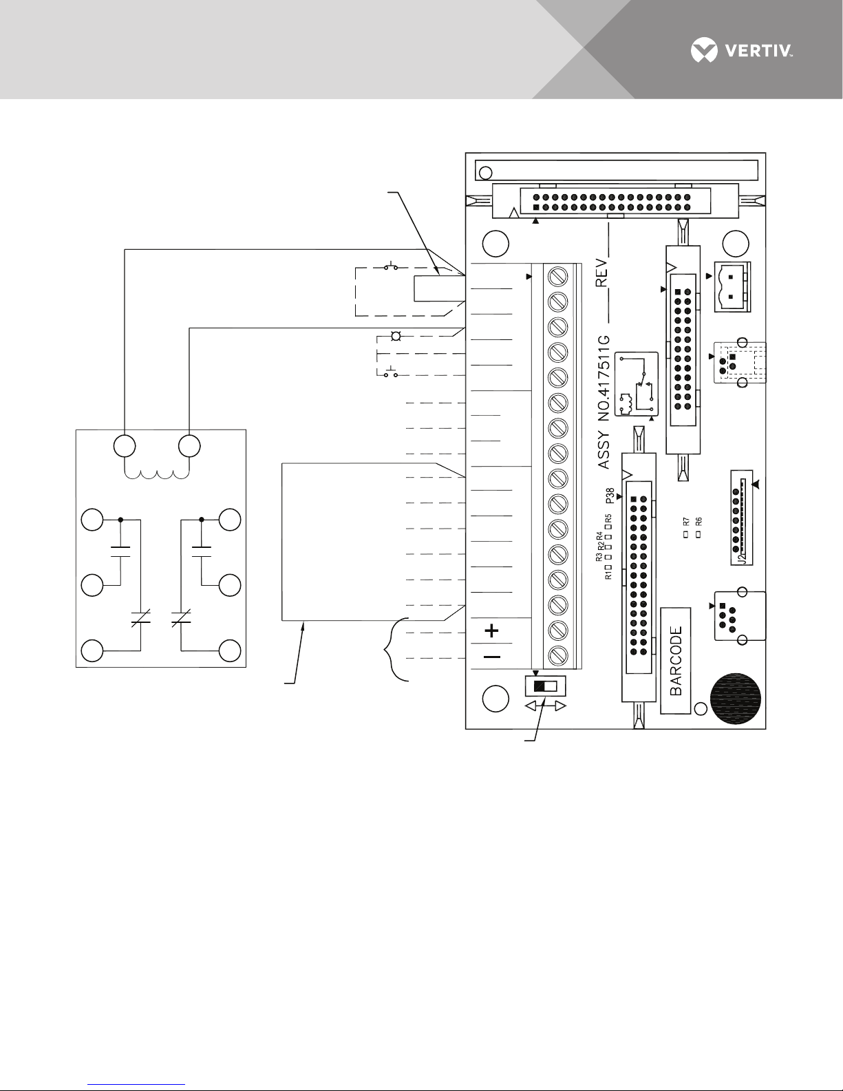
Figure 19 Control wiring for units without low-voltage control box
Building Interface Relay
Remove jumper when 5th customer
alarm is used.
Remove jumper when Normally
Closed (N.C.) REPO is used
Green
TB1
Summary Alarm NO
N.C.
REPO
Summary Alarm NC
Summary Alarm Common
W200
Customer Alarm Common
Customer Alarm #1 (N.O.)
Customer Alarm #2 (N.O.)
Customer Alarm #3 (N.O.)
Customer Alarm #4 (N.O.)
Customer Alarm #5 (N.C.)
To Liebert
SiteScan
®
System
N.O. REPO
Black
White
Customer Alarms
Summary
Alarm
Auto-Manual
Restart Switch
Auto
Manual
#1 NO
#2 NO
#3 NO
#4 NO
#5 NC
RS-485
EPORemote
Common
NO
NC
NO
REPO
COM
REPO
COM
NC
REPO
24VDC
24VDC
P1
K1
TB1
K1
P2
P38
P2
-24+
J1
J2
J3
J3
E1
J1
TB2
P1
P1 TO INTELLISLOT ONLY
S1
9
7
6
4
13
B
A
LDM13009
Rev. 1
NOTES
1. All switching devices are to be suitable for switching low current 24VDC. Minimum recommended wire size is 18AWG
stranded copper with 300V insulation.
All wiring and devices are field-supplied except where noted. See installation manual for detailed installation procedures.
2. The total load on the 24VDC supply (both N.O. and N.C. REPO circuits) must be limited to 1A.
3. Multiple Normally Open (N.O.) REPO switches may be paralleled.
Multiple Normally Closed (N.C.) REPO switches may be connected in series. All lamps (if used) are connected in parallel.
4. The summary alarm contacts are rated for 0 to 30VAC or VDC, 0.5A, 10W maximum.
5. Customer Alarms 1 through 4 are Normally Open (indicates alarm on contact closure). Customer Alarm 5 is Normally
Closed (indicates alarm on contact opening).
6. For Liebert SiteScan connection, use #22AWG shielded cable; maximum distance 1000ft (300m).
Vertiv | Liebert® PPC™ User Manual | Rev. 6 | 03/18 | 29
Page 34

1.3.7 Adapter Board
The Adapter Board (AB) provides customer interface to the Liebert PPC monitoring systems for units without
Low-Voltage Junction Box. Connections are made to terminal strip TB1 for Remote Emergency Power Off
(REPO) switches, summary alarm contacts and customer alarms (Liebert Power Monitor Panel with Velocity
Protocol [VPMP]; see 4.3 - Power Monitor Panel). The AB is mounted on top of the monitoring enclosure
located inside the top right corner of the unit.
A field-selectable switch (S1) on the AB allows the VPMP to be set up for either Manual or Auto restart. The
factory default setting is Manual.
• Manual Restart allows for an orderly, supervised startup after power failure. The control circuit automatically energizes
the shunt trip mechanism of the main input breaker upon sensing output voltage failure.
• Auto Restart deactivates the Manual Restart function. In Auto Restart mode, the main input breaker does not trip due to
power failure and the unit will restart when power is restored.
If two Liebert LDMF systems are provided, the summary alarm contacts from each Liebert LDMF are tied to the
Customer Summary Alarm on the adapter board.
Vertiv | Liebert® PPC™ User Manual | Rev. 6 | 03/18 | 30
Page 35

2.0 EQUIPMENT INSPECTION AND STARTUP
2.1 Internal Inspection
A detailed internal inspection should be performed after the unit is in place and before it is energized, to ensure
trouble free startup. The same internal inspection should be carried out when performing preventive
maintenance.
WARNING
Risk of electric shock. Can cause injury or death.
Verify that all incoming power and control circuits are de-energized and locked out before performing the
internal inspection.
Open the unit—Remove the exterior panels to gain access to the Liebert PPC’s internal components.
Visually inspect—Be sure wiring and components are not damaged.
Check power connections—Check all power connections for tightness. Refer to Tables 8 through 11 for torque
requirements of all electrical connections.
Perform formal detailed inspection—Follow the procedures described in 3.0 - INSPECTION AND STARTUP
CHECKLIST when performing detailed inspection.
2.2 Startup
Checklists—Follow the detailed step-by-step checklist (3.0 - INSPECTION AND STARTUP CHECKLIST)
when installing and starting up the Liebert PPC.
Initial system startup—A qualified electrician should be employed to perform the equipment inspection and
startup. Liebert system startup may be arranged by calling your local Liebert sales representative or Vertiv
Services. In the USA, call 800-543-2378.
Warranty effectivity—A copy of the appropriate checklist (furnished with the equipment) must be completed,
signed, dated, and returned to Vertiv. Warranty coverage of the equipment is not effective unless the checklist is
received by the factory.
WARNING
Risk of electric shock. Can cause injury or death.
Hazardous voltages are present during startup procedures. Equipment inspection and startup should be
performed only by properly trained and qualified personnel.
Electrical safety precautions must be followed throughout inspection and startup.
Vertiv | Liebert® PPC™ User Manual | Rev. 6 | 03/18 | 31
Page 36
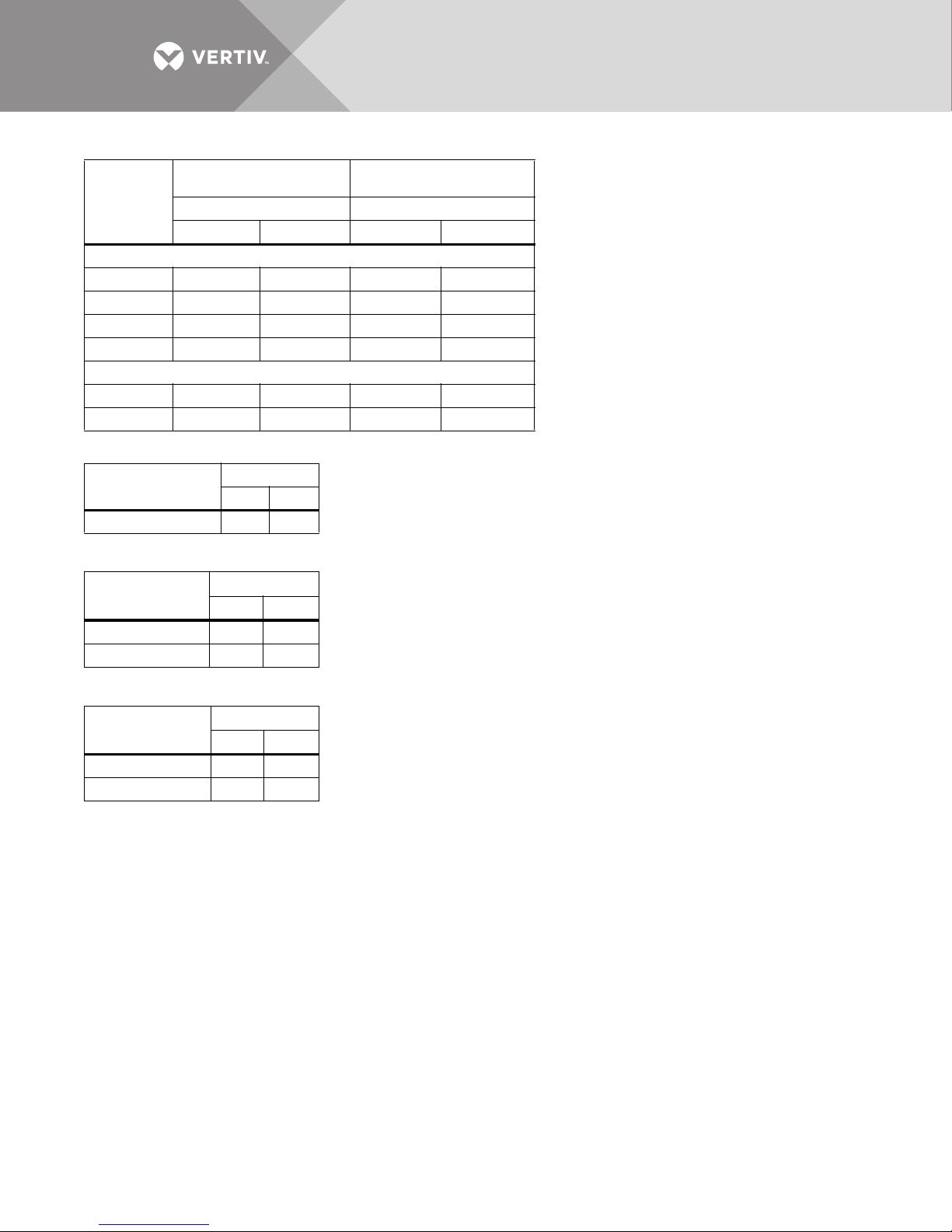
Table 8 Torque specifications, general
Electrical Connections
with 1 Belleville Washer
Tor qu e Tor qu e
lb-in N-m lb-in N-m
Bolt Shaft Size, in./mm
1/4 / M6 40 4.5 80 9.0
5/16 / M8 80 9.0 160 18.0
3/8 / M10 120 13.6 240 27.1
1/2 / M12 240 27.1 480 54.2
Input and Output Breakers
Up to 150A 80 9.0 160 18.0
175 - 500A 120 13.6 240 27.1
Electrical Connections
with 2 Belleville Washers
Table 9 Panelboard main circuit breaker torque specifications
Tor qu e
Connection
Busbar-to-Breaker 240 27.1
lb-in N-m
Table 10 Branch circuit breaker torque specifications
Tor qu e
Breaker Size
Up to 30A 20 4.0
40 to 100A 20 5.1
lb-in N-m
Table 11 Terminal block compression lug torque specifications
AWG Wire Size
or Range
#14 - #10 35 4.0
#8 40 4.5
Tor qu e
lb-in N-m
Vertiv | Liebert® PPC™ User Manual | Rev. 6 | 03/18 | 32
Page 37

3.0 INSPECTION AND STARTUP CHECKLIST
Unit Serial Number
Unit Model Number
Date:
3.1 Inspection
WARNING
Risk of electric shock. Can cause injury or death.
All equipment inspection procedures are to be performed with power to the unit turned Off and locked
out.
Exterior Inspection
___ 1. Confirm that the exterior of unit is undamaged (including cables and receptacles, if furnished).
___ 2. Confirm that service and ventilation clearances are adequate. (See Figures 1 through 4.)
Interior Inspection
___ 3. Remove accessible exterior panels.
NOTE
Disconnect the panel ground wires by separating the easy-disconnect terminals on the frame when removing
exterior panels. Reconnect all panel ground wires when replacing the exterior panels.
___ 4. Inspect all wire and conductor insulation for damage.
___ 5. Check all transformer terminal connections for tightness. Retorque if necessary.
___ 6. Check all breaker connections for tightness. Retorque if necessary.
___ 7. Check trip settings of adjustable breakers.
___ 8. Check all terminal block connections for tightness. Retorque if necessary.
___ 9. Check transformer mounting bolts for tightness. Retorque if necessary.
___ 10. Remove any foreign objects from the components or the interior area of the unit. Make sure air passages on
transformers are clear and free of debris!
___ 11. Check that the intake and exhaust air screens are clean and free of obstructions.
___ 12. Replace side panels, leaving access to circuit breakers for the following startup procedure.
NOTE
Reconnect the panel ground wires before replacing the side panels.
Vertiv | Liebert® PPC™ User Manual | Rev. 6 | 03/18 | 33
Page 38

3.2 Startup
WARNING
Risk of electric shock. Can cause injury or death.
Startup procedures should be performed only by properly trained and qualified personnel. Hazardous
voltages are present in the equipment throughout the majority of the startup procedure. Use proper
safety equipment. Proceed with caution.
1. Make certain that all circuit breakers are in the Off position and that power to the unit is locked out.
NOTE
Steps 2 through 6 apply to the Main Input Junction Box. If this installation is not provided with a Main Input
Junction Box, proceed to Step 7.
___ 2. Remove the cover of the Main Input Junction Box. Verify proper input power connections to unit, including equipment
grounding conductor.
___ 3. Turn ON the building power to the junction box. Check the phase rotation at the junction box. Phase rotation should be
A, B, C, as indicated.
___ 4. Check and record the input voltages at the junction box:
Volts, phase A to phase B = ______________________
Volts, phase B to phase C = ______________________
Volts, phase C to phase A = ______________________
___ 5. Turn Off and lock out the building power to the input junction box.
___ 6. Replace the junction box cover.
___ 7. Verify proper input power connections to unit, including equipment grounding conductor and local grounding electrode
conductor.
___ 8. Turn On the building input power to the unit.
___ 9. Check phase rotation at main input breaker. Phase rotation should be A, B, C, left-to-right.
___ 10. Check and record the input voltage at the main input breaker. Measured voltages should correspond to the unit’s
nameplate input voltage.
Volts, phase A to phase B = ______________________
Volts, phase B to phase C = ______________________
Volts, phase C to phase A = ______________________
___ 11. Turn ON the main input breaker; wait one minute. (If breaker trips Off, check for wiring errors including control
connections. Contact Vertiv Services or the location factory representative for assistance.)
___ 12. Check the phase rotation at the line side terminals (top) of the panelboard main breaker(s) and any subfeed output
circuit breaker(s). The rotation should be A, B, C, left-to-right.
___ 13. Check and record the voltages at the line-side terminals of the output circuit breaker. Measured voltages should
correspond to the unit’s nameplate output voltage (within +4%,-0%).
Volts, phase A to phase B = ______________________
Volts, phase B to phase C = ______________________
Volts, phase C to phase A = ______________________
Volts, phase A to neutral = ______________________
Volts, phase B to neutral = ______________________
Volts, phase C to neutral = ______________________
If output voltage is incorrect, check for wiring errors, incorrect input voltage, or improper transformer tap. Contact Vertiv
Services at 800-543-2378 in the USA or the local factory representative for assistance.
Vertiv | Liebert® PPC™ User Manual | Rev. 6 | 03/18 | 34
Page 39

NOTE
The Liebert PPC transformer has input voltage taps for each input phase. The taps are arranged in 2-1/2% or 5%
intervals ranging from -10% to nominal to +5%. This permits the transformer to provide the proper output
voltage for a range of input voltages. Should it be necessary, the tap arrangement may be changed to match the
input voltage:
• Open main input circuit breaker.
• Select tap arrangement to match input voltage. (Refer to transformer nameplate for tap information.)
• Secure each line to its proper tap.
• Repeat Steps 11 to 13.
___ 14. Depress the local Emergency Power Off switch and verify system shutdown. Turn the unit back On.
___ 15. Repeat Step 14 for each REPO switch with which the system is equipped.
NOTICE
Risk of shutting down systems inadvertently. Can cause equipment damage.
Using the REPO switch may shut down more equipment or systems than just the Liebert PPC. Ascertain whether
necessary systems might be shut down before performing the procedure.
3.3 Monitoring System Check-Out
___ 16. BASIC INDICATORS
a. Turn On the building power to the unit, then turn the Main Input Breaker On.
b. Check that the Power LED on the front panel is illuminated.
___ 17. MANUAL RESTART CHECK. If unit is equipped with Manual Restart:
a. Turn On building power to the unit. Turn Main Input breaker On.
b. Turn Off all building power to unit.
c. Observe that Main Input Breaker automatically trips open upon power loss.
d. Restore building power to the unit and return Main Input breaker to On.
___ 18. POWER MONITOR PANEL. If unit is equipped with a Power Monitor Panel:
Turn the unit On. Ensure that the voltage values indicated by the Monitor Panel correspond to the voltage values
measured at the input and output circuit breaker (Steps 10 and 13).
___ 19. CENTRALIZED MONITOR. If the unit is connected to a Centralized Monitoring System:
Turn the unit and Centralized Monitoring System On. Verify proper communication to the monitor system operation.
___ 20. CONTROL VOLTAGE:
a. Obtain access to the low voltage terminals in the Low-Voltage Junction Box (if used), or in the low voltage control
section inside unit.
b. With the unit On, measure and record the DC control voltage on Terminals +Vout (+) and -Vout (-).
c. Control Voltage =
(Voltage should be 12VDC ±5%.)
___ 21. CUSTOMER ALARMS. If customer alarms are provided:
a. With the unit On, simulate alarm operation by jumpering the appropriate low-voltage control terminals. (Refer to the
control wiring installation drawing furnished with the unit.)
b. Verify correct alarm annunciation by the Power Monitor Panel and/or by the Centralized Monitoring System.
Vertiv | Liebert® PPC™ User Manual | Rev. 6 | 03/18 | 35
Page 40

3.4 Equipment Connection Check-Out (For Units With Distribution Cables)
WARNING
Risk of electric shock. Can cause injury or death.
All loads should be disconnected or turned off before proceeding with the following steps.
For units with output distribution cables, be sure that there are no output receptacles connected to load
equipment plugs and that the receptacles are not in contact with foreign objects.
Pay special attention to those output cables intended for direct wiring connection; the exposed
conductor ends of these cables must not be in contact with each other or with any foreign objects.
___ 22. Turn On main input power to the unit.
___ 23. Turn On the panelboard main output breaker(s).
___ 24. Individually turn On each branch circuit breaker and check the output voltage (also phase rotation, if a 3-phase circuit)
at the receptacle or cable end.
___ 25. Turn Off all branch circuit breakers and the panelboard main output circuit breaker(s).
___ 26. Connect the load equipment per equipment manufacturer’s specifications and recommendations.
___ 27. Turn On the panelboard main output breaker(s).
___ 28. Turn On branch circuit breakers to the load equipment.
Observe the power-up sequence recommended by the equipment manufacturer.
___ 29. Verify that all load equipment operates properly.
___ 30. Replace all unit panels.
After performing the inspection and startup procedure described in 3.0 - INSPECTION AND STARTUP
CHECKLIST in this manual, complete the Startup and Inspection form furnished with the unit, sign the
completed form and return it to:
Liebert Corporation
1050 Dearborn Drive
P.O. Box 29186
Columbus, Ohio 43229 USA
NOTE
Warranty is not in effect unless Inspection and Startup form is received by the factory.
Vertiv | Liebert® PPC™ User Manual | Rev. 6 | 03/18 | 36
Page 41

4.0 OPERATING INSTRUCTIONS
4.1 Startup Procedures
Before the unit is placed into service after initial installation, after equipment relocation, or after equipment has
been de-energized for an extended period of time, perform equipment inspection and startup procedures as
detailed in 2.0 - EQUIPMENT INSPECTION AND STARTUP and 3.0 - INSPECTION AND STARTUP
CHECKLIST.
After initial system startup, the following guidelines can be used for standard equipment operation. These
guidelines should be reviewed for any special equipment modifications, special site considerations, or company
policies which may require changes to the standard equipment operation.
4.1.1 Emergency Shutdown
To perform an immediate system shutdown during emergency conditions, lift the clear, protective cover and
push the “Emergency Power Off” (EPO) switch on the unit front door.
NOTE
Depending on the particular control circuit wiring, operation of the unit EPO switch may cause other equipment
to also shutdown.
To perform an immediate room shutdown, if the site is equipped with a REPO switch (as required by NEC Article
645 at the principal exit doors), activate one of the REPO switches.
4.1.2 Normal System Shutdown
To perform a normal system shutdown, perform an orderly load equipment (computer system) shutdown
according to the load equipment manufacturer’s recommended shutdown sequence. The load equipment can be
turned Off at each piece of load equipment or at the Liebert PPC’s output distribution (circuit breaker) panels
located behind the unit’s front door. Turn Off all unit output breakers, then turn Off the unit’s main input circuit
breaker. To remove all power from the unit, turn Off the building power to the unit’s input breaker or junction box.
4.1.3 Normal System Turn ON
Make certain all unit circuit breakers are in the Off position. All unit circuit breakers are located behind the front
doors. Turn On building power to the unit. Turn On the unit’s main input circuit breaker. If the circuit breaker has
been tripped Off (instead of being turned Off), the circuit breaker handle must be moved to the Off position
before being turned On. If the unit has a voltage monitoring panel, verify proper output voltages before turning
On output circuit breakers. Turn On the panelboard main breakers. Individually turn On each output circuit
breaker following the load equipment manufacturer’s startup sequence.
4.1.4 Manual Restart
If unit’s manual restart feature has been selected, the unit’s main input circuit breaker will be tripped upon a
power outage, preventing repetitive application of unstable voltage and allowing for an orderly system restart. If
the main input circuit breaker is tripped upon a power outage, after power is restored, follow the instructions
outlined in 4.1.3 - Normal System Turn ON.
Vertiv | Liebert® PPC™ User Manual | Rev. 6 | 03/18 | 37
Page 42
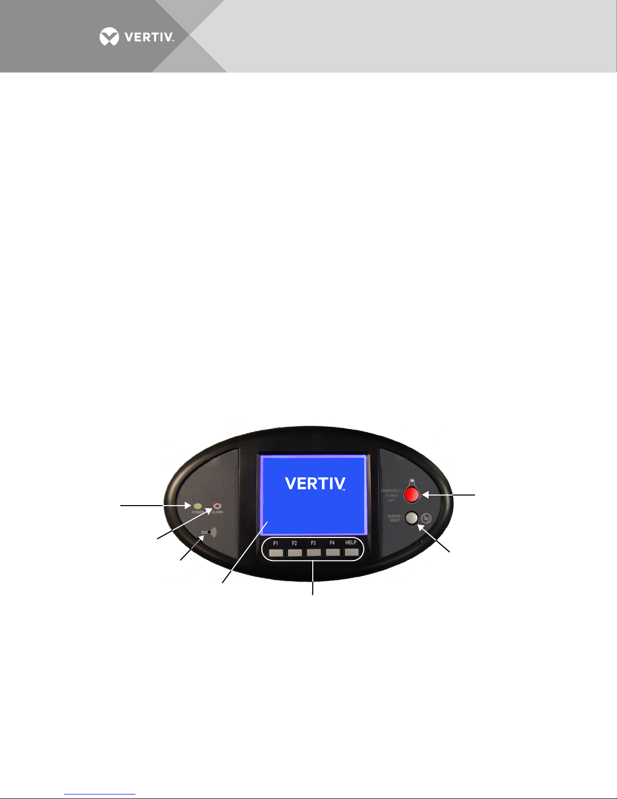
4.2 Basic Monitor Panel
Navigation keys
Alarm Silence/Reset
push button
Audible
Alarm
speaker
Alarm Status Indicator
Red
Power Indicator
Green
LCD viewing
area
Emergency Power Off
(EPO) Push Button
Basic Monitoring provides transformer overtemperature alarm, transformer overtemperature shutdown and
Emergency Power Off controls only.
4.2.1 Display Controls and Indicators
• Power Indicator (Green LED)—Illuminates when power has been applied to the Liebert AC Power product.
• Alarm Status Indicator (Red LED)—Illuminates when an alarm is present. The LED will remain illuminated until the alarm
condition is cleared.
• Audible Alarm speaker (represented by the speaker symbol)—A speaker behind the bezel will sound when there is an
alarm condition.
• Silence/Reset Push Button—Press and release the Silence/Reset button to silence the audible alarm. Press and hold the
button to clear the alarm and turn Off the red alarm indicator LED. If the alarm condition still exists the alarm will be
annunciated again.
• Emergency Power Off (EPO) Push Button—Pressing the EPO button shunt trips the input circuit breaker to turn the unit
Off.
• LCD—Note used.
• Navigation keys (soft function keys F1 through F4 and Help)—Not used.
If an overtemperature condition occurs—when the transformer temperature exceeds
356°F (180°C)—it should be investigated and corrected. Possible causes include transformer overload, excessive
non-linear loading, inadequate ventilation, high or low input voltage and monitoring malfunction.
Failure to correct the overtemperature condition may result in an automatic system shutdown due to the second
stage of overtemperature sensing, when the transformer temperature exceeds 392°F (200°C). After the alarm
condition is corrected, the alarm will automatically reset.
See Figure 17 for remote summary alarm and Remote Emergency Power Off switch connections.
Figure 20 Liebert PPC controls and indicators
Vertiv | Liebert® PPC™ User Manual | Rev. 6 | 03/18 | 38
Page 43

4.3 Power Monitor Panel
Liebert Power Monitor Panel with Velocity Protocol (VPMP) provides input voltage, output current and voltage
and other power parameters and will detect and annunciate alarm messages. The monitored parameters and
alarms will be displayed on the local display and be available for communication to a customer or Liebert
monitoring system.
The VPMP includes a monochrome Liquid Crystal Display (LCD), power and alarm LEDs, an audible alarm and
alarm silence and Emergency Power Off push buttons mounted on the front door.
Display Controls and Indicators
• Power Indicator (Green LED)—Illuminates when power has been applied to the Liebert AC Power product.
• Alarm Status Indicator (Red LED)—Illuminates when the VPMP detects an alarm. The LED will remain illuminated until the
alarm condition is cleared.
• Audible Alarm speaker (represented by the speaker symbol)—A speaker behind the bezel will sound when the Liebert
VPMP records an alarm condition.
• Silence/Reset Push Button—Press and release the Silence/Reset button to silence the audible alarm. Press and hold the
button to clear the alarm and turn Off the red alarm indicator LED. If the alarm condition still exists the alarm will be
annunciated again.
• Emergency Power Off (EPO) Push Button—Pressing the EPO button shunt trips the input circuit breaker to turn the unit
Off.
• LCD—Displays power parameters and alarm data.
• Navigation keys (soft function keys F1 through F4 and Help):
• F1 selects the next Main Breaker or Next Subfeed.
• F2 is the Sequence key. It selects the next set of items at the current level or the next item on a list.
• F3 can select Subfeed (if supplied and monitored) at the top level or can select a menu item at a lower level.
• F4 can select Branch a Back function at lower levels.
Pressing the Back key (F4) navigates to the top level (Main) except from the Help screen.
From the Help screen, the Back key navigates to the previous screen.
• Pressing the Help key navigates to the Help screen.
All alarm thresholds for monitored parameters are adjustable by way of the VPMP DB-9 setup port to match site
requirements. All alarms are stored in non-volatile memory to protect against erasure by a power outage. Alarms
must be reset manually after the alarm condition has been corrected. Alarms may be reset by pushing the
Silence/Reset button on the display or through the remote monitoring system (if used).
The following metering parameters may be displayed:
• Input Voltage, Line-to-Line for all three phases
• Output Voltages, Line-to-Line for all three phases
• Output Voltages, Line-to-Neutral for all three phases
• Output Voltage Total Harmonic Distortion (THD) for all three phases
• Output Current for all three phases
• Output Current Total Harmonic Distortion (THD) for all three phases
• Output Current Crest Factor (Peak/RMS) for all three phases
• Output Current Harmonic K-Factor for all three phases
• Output Neutral Current
• System Ground Current
•Output Frequency
•Output kVA
•Output kW
•Output Power Factor
• Output kW-Hours
•Percent Load
•Date
•Time
Vertiv | Liebert® PPC™ User Manual | Rev. 6 | 03/18 | 39
Page 44

The VPMP detects and annunciates by alarm message the following conditions:
• Output Overvoltage
• Output Undervoltage
• Output Overcurrent
• Neutral Overcurrent
• Ground Overcurrent
• Output Voltage Distortion
• Frequency Deviation
•Phase Sequence Error
• Phase Loss
• Transformer Overtemperature
All alarm thresholds for monitored parameters are adjustable by way of the VPMP DB-9 setup port to match site
requirements. The factory setpoints for the alarms are as follows:
• Output Overvoltage— voltage exceeds +6% of nominal
• Output Undervoltage— voltage falls below - 13% of nominal
• Output Overcurrent— current exceeds 95% of full load amps
• Neutral Overcurrent— current exceeds 95% of full load amps
• Ground Overcurrent— current exceeds: 5 amps (15-125kVA); 10 amps (150-225kVA)
• Output Voltage Distortion—output voltage THD exceeds 10%
• Frequency Deviation—output frequency exceeds ±0.5Hz of nominal
Summary Alarm
• Summary Alarm—Detects and annunciates any alarm.
Summary Alarm Contacts
• The VPMP has a Form C (one NO and one NC) summary alarm contact for remote alarm status. The contacts are rated at
24VAC @ 1A. The contacts change state upon occurrence of any alarm including warnings and resets when the alarm is
cleared. Summary alarm contacts are located on the adapter board. The adapter board is on top of the monitoring
enclosure. See Figure 19 for details.
Communication—Liebert IntelliSlot™ cards provide customer connections to a Building Management System
(BMS) or Remote Monitoring Systems. The following cards are available:
• IS-WEBS Card provides SNMP/WEB output. An RJ-45 connector is supplied for customer connection to Ethernet LAN.
• IS-485S Card provides Modbus 485 output. A terminal strip is provided for 2-wire connection.
• IS-IPBMS Card provides Modbus IP output. An RJ-45 connector is supplied for customer connection.
• IS-UNITY-DP Card provides HTTP/HTTPS, Vertiv Protocol, e-mail, SMS, SNMP v1/v2c/v3, BACnet IP/MSTP and Modbus
TCP/RTU output using a serial RS-485 two-wire connection.
Up to three cards can be plugged into the Liebert IntelliSlot ports provided with the VPMP system.
If communication to Liebert SiteScan® is required, customer connection can be made to the adapter board RS485 terminals on TB1, see Figure 19 for details. The adapter board is located on top of the monitoring enclosure.
Vertiv | Liebert® PPC™ User Manual | Rev. 6 | 03/18 | 40
Page 45

4.4 Liebert Current Plus Monitoring (If Supplied)
Liebert Current Plus Monitoring (Liebert CPM) provides the current and voltage of each panelboard main circuit
breaker. These measurements are used for reporting the average RMS current, power and other parameters. The
Liebert CPM detects and annunciates alarm messages and status conditions for each panelboard main circuit
breaker. The monitored parameters and alarms appear on the local display and are available for communication
to a customer or Liebert monitoring system.
The Liebert CPM includes a monochrome LCD, power and alarm LED’s, an audible alarm and alarm silence and
Emergency Power Off push buttons mounted on the front door.
Display Controls and Indicators
• Power Indicator (Green LED)—Illuminates when power has been applied to the Liebert AC Power product.
• Alarm Status Indicator (Red LED)—Illuminates when the Liebert CPM detects an alarm. The LED will remain illuminated
until the alarm condition is cleared.
• Audible Alarm speaker (represented by the speaker symbol)—A speaker behind the bezel will sound when the Liebert
CPM records an alarm condition.
• Silence/Reset Push Button—Press and release the Silence/Reset button to silence the audible alarm. Press and hold the
button to clear the alarm and turn Off the red alarm indicator LED. If the alarm condition still exists the alarm will be
annunciated again.
• Emergency Power Off (EPO) Push Button—Pressing the EPO button shunt trips the input circuit breaker to turn the unit
Off.
• LCD—Displays power parameters and alarm data.
• Navigation keys (soft function keys F1 through F4 and Help):
• F1 selects the next Main Breaker.
• F2 is the Sequence key. It selects the next set of items at the current level or the next item on a list.
• F3 can select a menu item.
• F4 can provide a Back function at lower levels.
Pressing the Back key (F4) navigates to the top level (Main) except from the Help screen.
From the Help screen, the Back key navigates to the previous screen.
• Pressing the Help key navigates to the Help screen.
All alarm thresholds for monitored parameters are adjustable by way of the DB-9 setup port to match site
requirements. All alarms are stored in non-volatile memory to protect against erasure by a power outage. Alarms
must be reset manually after the alarm condition has been corrected. Alarms may be reset by pushing the
Silence/Reset button on the display or through the remote monitoring system (if used).
The Liebert CPM monitors and displays the following parameters for the panelboard main circuit breaker:
•Phase Current
•Percent Load
•kW
•kW-Hours
The following metering parameters may be displayed:
• Voltage—Line-to-Line
• Voltage—Line-to-Neutral
• Neutral Current
• Ground Current
•kVA
• Power Factor
• Voltage Total Harmonic Distortion (THD)
• Current Total Harmonic Distortion (THD)
•Crest Factor
Circuit identification and status of each breaker may be displayed.
Vertiv | Liebert® PPC™ User Manual | Rev. 6 | 03/18 | 41
Page 46

The Liebert CPM detects and annunciates by alarm message the following conditions:
•Overvoltage
• Undervoltage
• Neutral Overcurrent
• Ground Overcurrent
• Phase Overcurrent
• Phase Overcurrent Warning
• Summary Alarm
All alarm thresholds for monitored parameters are adjustable by way of the DB-9 setup port to match site
requirements. The factory setpoints for the alarms are as follows:
• Overvoltage—At least one of the line-to-line voltages exceeds +6% of nominal
• Undervoltage—At least one of the line-to-line or line-to-neutral voltages falls below -13% of nominal
• Phase Overcurrent Warning—Current exceeds 75% of breaker amps
• Phase Overcurrent—Current exceeds 80% of breaker amps
• Neutral Current—Current exceeds 95% of breaker amps
• Ground Current—Current exceeds 5A (15-125kVA); 10A (150-225kVA)
Summary Alarm
• Summary Alarm—Detects and annunciates any alarm.
Summary Alarm Contacts
• The LDMF has a Form C (one NO and one NC) summary alarm contact for remote alarm status. The contacts are rated at
24VAC @ 1A. The contacts change state upon occurrence of any alarm including warnings and reset when the alarm is
cleared. Summary alarm contacts are located on the adapter board. The adapter board is on top of the monitoring
enclosure. See Figure 19 for details.
Communication—Liebert IntelliSlot™ cards provide customer connections to a Building Management System
(BMS) or Remote Monitoring Systems. The following cards are available:
• IS-WEBS Card provides SNMP/WEB output. An RJ-45 connector is supplied for customer connection to Ethernet LAN.
• IS-485S Card provides Modbus 485 output. A terminal strip is provided for two-wire connection.
• IS-IPBMS Card provides Modbus IP output. An RJ-45 connector is supplied for customer connection.
• IS-UNITY-DP card provides HTTP/HTTPS, Vertiv Protocol, e-mail, SMS, SNMP v1/v2c/v3, BACnet IP/MSTP and
Modbus TCP/RTU output using a serial RS-485 two-wire connection
Up to three Liebert IntelliSlot cards may be installed in the Liebert CPM system.
If communication to Liebert SiteScan® is required, customer connection can be made to the adapter board
RS-485 terminals on TB1, see Figure 19 for details. The adapter board is located on top of the monitoring
enclosure.
Vertiv | Liebert® PPC™ User Manual | Rev. 6 | 03/18 | 42
Page 47

4.5 Liebert Distribution Monitoring (If Supplied)
The Liebert Distribution Monitoring (Liebert LDMF) provides the current and voltage for each branch circuit
breaker mounted on the panelboards and the panelboard main circuit breaker. These measurements are used
for reporting the average RMS current, power and other parameters. The Liebert LDMF detects and annunciates
alarm messages and status conditions for each branch circuit breaker and the panelboard main circuit breaker.
The monitored parameters and alarms appear on the local display (if supplied) and are available for
communication to a customer or Liebert monitoring system.
The Liebert LDMF (if supplied) includes a monochrome LCD, power and alarm LEDs, an audible alarm and alarm
silence and Emergency Power Off push buttons mounted on the front door.
Display Controls and Indicators
• Power Indicator (Green LED)—Illuminates when power has been applied to the Liebert AC Power product.
• Alarm Status Indicator (Red LED)—Illuminates when the Liebert LDMF detects an alarm. The LED will remain illuminated
until the alarm condition is cleared.
• Audible Alarm speaker (represented by the speaker symbol)—A speaker behind the bezel will sound when the
Liebert LDMF records an alarm condition.
• Silence/Reset Push Button—Press and release the Silence/Reset button to silence the audible alarm. Press and hold the
button to clear the alarm and turn Off the red alarm indicator LED. If the alarm condition still exists the alarm will be
annunciated again.
• Emergency Power Off (EPO) Push Button—Pressing the EPO button shunt trips the input circuit breaker to turn the unit
Off.
• LCD—Displays power parameters and alarm data.
• Navigation keys (soft function keys F1 through F4 and Help):
• F1 selects the next Main Breaker, Next Subfeed or Next Branch.
• F2 is the Sequence key. It selects the next set of items at the current level or the next item on a list.
• F3 can select Subfeed (if supplied and monitored) at the top level or a menu item at a lower level.
• F4 can select Branch Breakers at the top level or provide a Back function at lower levels.
Pressing the Back key (F4) navigates to the top level (Main) except from the Help screen.
From the Help screen, the Back key navigates to the previous screen.
• Pressing the Help key navigates to the Help screen.
All alarm thresholds for monitored parameters are adjustable by way of the LDMF DB-9 setup port to match site
requirements. All alarms are stored in non-volatile memory to protect against erasure by a power outage. Alarms
must be reset manually after the alarm condition has been corrected. Alarms may be reset by pushing the
Silence/Reset button on the display or through the remote monitoring system (if used).
The Liebert LDMF monitors and displays the following parameters for the panelboard main circuit breaker, each
branch circuit breaker and subfeed circuit breakers (if supplied and monitored):
•Phase Current
•Percent Load
•kW
•kW-Hours
The following metering parameters may be displayed:
• Voltage—Line-to-Line
• Voltage—Line-to-Neutral
• Neutral Current
• Ground Current
•kVA
• Power Factor
• Voltage Total Harmonic Distortion (THD)
• Current Total Harmonic Distortion (THD)
•Crest Factor
Vertiv | Liebert® PPC™ User Manual | Rev. 6 | 03/18 | 43
Page 48

Circuit identification and status of each breaker may be displayed.
The Liebert LDMF detects and annunciates by alarm message the following conditions:
•Overvoltage
• Undervoltage
• Neutral Overcurrent
• Ground Overcurrent
• Phase Overcurrent
• Phase Overcurrent Warning
• Summary Alarm
All alarm thresholds for monitored parameters are adjustable by way of the LDMF DB-9 setup port to match site
requirements. The factory setpoints for the alarms are as follows:
• Overvoltage—At least one of the line-to-line voltages exceeds +6% of nominal.
• Undervoltage—At least one of the line-to-line or line-to-neutral voltages falls below -13% of nominal.
• Phase Overcurrent Warning—Current exceeds 75% of breaker amps.
• Phase Overcurrent—Current exceeds 80% of breaker amps.
• Neutral Current—Current exceeds 95% of breaker amps.
• Ground Current—Current exceeds 5A (15-125kVA); 10A (150-225kVA).
Summary Alarm
• Summary Alarm—Detects and annunciates any alarm.
Summary Alarm Contacts
• The CPM has a Form C (one NO and one NC) summary alarm contact for remote alarm status. The contacts are rated at
24VAC @ 1A. The contacts change state upon occurrence of any alarm including warnings and resets when the alarm is
cleared. Summary alarm contacts are located on the adapter board. The adapter board is on top of the monitoring
enclosure. See Figure 19 for details.
Communication—Liebert IntelliSlot™ cards provide customer connections to a Building Management System
(BMS) or Remote Monitoring Systems. The following cards are available:
• IS-WEBS Card provides SNMP/WEB output. An RJ-45 connector is supplied for customer connection to Ethernet LAN.
• IS-485S Card provides Modbus 485 output. A terminal strip is provided for two-wire connection.
• IS-IPBMS Card provides Modbus IP output. An RJ-45 connector is supplied for customer connection.
• IS-UNITY-DP Card provides HTTP/HTTPS, Vertiv Protocol, e-mail, SMS, SNMP v1/v2c/v3, BACnet IP/MSTP and
Modbus TCP/RTU output using a serial RS-485 two-wire connection
Up to three cards can be plugged into the Liebert IntelliSlot™ ports provided with the Liebert LDMF system.
If communication to Liebert SiteScan® is required, customer connection can be made to the adapter board
RS-485 terminals on TB1; see Figure 19 for details. The adapter board is on top of the monitoring enclosure.
Vertiv | Liebert® PPC™ User Manual | Rev. 6 | 03/18 | 44
Page 49

5.0 MAINTENANCE
5.1 Corrective Maintenance
Even the most reliable equipment may fail. Vertiv Services is at your service to assure fast repair of your unit and
minimum down-time of your installation.
WARNING
Risk of electric shock. Can cause injury or death.
Hazardous voltages are present within the Liebert PPC. Only properly trained and qualified service
personnel should perform maintenance on the Liebert PPC system. All voltage sources to the unit must
be disconnected before inspecting or cleaning within the cabinet.
Standard electrical troubleshooting procedures should be used to isolate problems in the unit. If there are
questions, don’t hesitate to contact Vertiv Services.
Repair or replacement of standard items, such as circuit breakers, fuses, transformers, capacitors and indicator
lights can be either handled by qualified electricians or referred to Vertiv Services.
Repairs related to the monitoring system should be referred to Vertiv Services.
To contact Vertiv Services for information or repair service in the USA, call 800-543-2378.
5.2 Preventive Maintenance (Inspection and Cleaning)
Air circulation through the cabinet may cause dust to accumulate on internal components. Cleaning should be
done as necessary during electrical inspections.
Annual general system inspections, cleaning, and operation checks are recommended to ensure system
performance and long service life.
WARNING
Risk of electric shock. Can cause injury or death.
Hazardous voltages are present within the Liebert PPC. Only properly trained and qualified service
personnel should perform maintenance on the Liebert PPC system. All voltage sources to the unit must
be disconnected before inspecting or cleaning within the cabinet.
Inspection Schedule
• It is difficult to establish a schedule for periodic cleanings since conditions vary from site to site. Inspections after the first
24 hours, 30 days and 6 months of operation should help determine a pattern for the inspection schedule.
• Electrical connections and component mountings should be inspected after the first 24 hours, 30 days, and 6 months of
operation. Inspections should be conducted annually thereafter.
• Ventilation openings and grilles should be inspected and cleaned every six months to one year.
• A complete inspection and operational checkout should be performed annually. This is best done by performing the
inspection and startup procedure as detailed in 3.0 - INSPECTION AND STARTUP CHECKLIST.
• Vertiv Services offers a complete range of preventive maintenance services. These include thorough equipment
performance checks and calibration of electronics. Contact Vertiv Services in the USA at 800-543-2378 for details.
Vertiv | Liebert® PPC™ User Manual | Rev. 6 | 03/18 | 45
Page 50

NOTES
Vertiv | Liebert® PPC™ User Manual | Rev. 6 | 03/18 | 46
Page 51

TECHNICAL SUPPORT / SERVICE
Web Site
www.vertivco.com
Monitoring
800-222-5877
Outside North America: +00800 1155 4499
Three-Phase UPS & Power Systems
800-543-2378
Outside North America: 614-841-6598
LOCATIONS
United States
1050 Dearborn Drive
P.O. B ox 2 918 6
Columbus, OH 43229
Europe
Via Leonardo Da Vinci 8
Zona Industriale Tognana
35028 Piove Di Sacco (PD) Italy
+39 049 9719 111
Fax: +39 049 5841 257
Asia
29/F, The Orient Square Building
F. Ortigas Jr. Road, Ortigas Center
Pasig City 1605
Philippines
+63 2 687 6615
Fax: +63 2 730 9572
Page 52

VertivCo.com | Vertiv Headquarters, 1050 Dearborn Drive, Columbus, OH, 43085, USA
© 2016 Vertiv Co. All rights reserved. Vertiv and the Vertiv logo are trademarks or registered trademarks of Vertiv Co. All other names and logos referred to are trade names, trademarks or registered trademarks of their respective owners.
While every precaution has been taken to ensure accuracy and completeness herein, Vertiv Co. assumes no responsibility, and disclaims all liability, for damages resulting from use of this information or for any errors or omissions. Specifications are subject to
change without notice.
SL-20140_REV6_03-18
 Loading...