

Vertiv Liebert NX 225 kVA, Liebert NX 400 kVA, Liebert NX 300 kVA, Liebert NX 250 kVA, Liebert NX 600 kVA Installation Manual
...Page 1

Liebert® NX™ UPS
Installation Manual — 225-600kVA, 1.0PF, 60Hz, Three-Phase, Single-Module &
Multi-Module
Page 2

CONTACTING VERTIV FOR SUPPORT
To contact Vertiv Liebert Services for information or repair service in the United States, call 800-543-2378.
Liebert Services offers a complete range of startup services, repair services, preventive maintenance plans and
service contracts.
For repair or maintenance service outside the 48 contiguous United States, contact Liebert Services, if available
in your area. For areas not covered by Liebert Services, the authorized distributor is responsible for providing
qualified, factory-authorized service.
For Liebert Services to assist you promptly, please have the following information available:
Part numbers: ___________________________________________________________________________________________________________
Serial numbers:__________________________________________________________________________________________________________
Rating: __________________________________________________________________________________________________________________
Date purchased:_________________________________________________________________________________________________________
Date installed: ___________________________________________________________________________________________________________
Location: ________________________________________________________________________________________________________________
Input voltage/frequency:________________________________________________________________________________________________
Output voltage/frequency:______________________________________________________________________________________________
Battery reserve time:____________________________________________________________________________________________________
Product Warranty Registration
To register for warranty protection, visit the Service and Support section of our Web site at:
www.liebert.com
Click on Product Registration and fill out the form.
Page 3

TABLE OF CONTENTS
CONTACTING VERTIV FOR SUPPORT . . . . . . . . . . . . . . . . . . . . . . . . . . . . . . . INSIDE FRONT COVER
IMPORTANT SAFETY INSTRUCTIONS . . . . . . . . . . . . . . . . . . . . . . . . . . . . . . . . . . . . . . . . . . . . . . . .1
SAVE THESE INSTRUCTIONS . . . . . . . . . . . . . . . . . . . . . . . . . . . . . . . . . . . . . . . . . . . . . . . . . . . . . . . . 1
1.0 MECHANICAL INSTALLATION . . . . . . . . . . . . . . . . . . . . . . . . . . . . . . . . . . . . . . . . . . . . . . . . 3
1.1 Introduction . . . . . . . . . . . . . . . . . . . . . . . . . . . . . . . . . . . . . . . . . . . . . . . . . . . . . . . . . . . . . . . . . . . . . . . . . . . . . . . . . . . . . .3
1.2 Preliminary Checks . . . . . . . . . . . . . . . . . . . . . . . . . . . . . . . . . . . . . . . . . . . . . . . . . . . . . . . . . . . . . . . . . . . . . . . . . . . . . . .3
1.3 Environmental Considerations. . . . . . . . . . . . . . . . . . . . . . . . . . . . . . . . . . . . . . . . . . . . . . . . . . . . . . . . . . . . . . . . . . . . 4
1.3.1 UPS Room. . . . . . . . . . . . . . . . . . . . . . . . . . . . . . . . . . . . . . . . . . . . . . . . . . . . . . . . . . . . . . . . . . . . . . . . . . . . . . . . . . . . . . . . 4
1.3.2 Storing the UPS and Batteries for Delayed Installation. . . . . . . . . . . . . . . . . . . . . . . . . . . . . . . . . . . . . . . . . . . . . . 4
1.3.3 Installation Altitude . . . . . . . . . . . . . . . . . . . . . . . . . . . . . . . . . . . . . . . . . . . . . . . . . . . . . . . . . . . . . . . . . . . . . . . . . . . . . . . 5
1.4 Positioning . . . . . . . . . . . . . . . . . . . . . . . . . . . . . . . . . . . . . . . . . . . . . . . . . . . . . . . . . . . . . . . . . . . . . . . . . . . . . . . . . . . . . . .5
1.4.1 Moving the Cabinets . . . . . . . . . . . . . . . . . . . . . . . . . . . . . . . . . . . . . . . . . . . . . . . . . . . . . . . . . . . . . . . . . . . . . . . . . . . . . . 5
1.4.2 Clearances . . . . . . . . . . . . . . . . . . . . . . . . . . . . . . . . . . . . . . . . . . . . . . . . . . . . . . . . . . . . . . . . . . . . . . . . . . . . . . . . . . . . . . . 5
1.4.3 Raised-Floor Installations . . . . . . . . . . . . . . . . . . . . . . . . . . . . . . . . . . . . . . . . . . . . . . . . . . . . . . . . . . . . . . . . . . . . . . . . . 5
1.4.4 Kick Plates and Floor Anchors for Special Seismic Certification—Optional . . . . . . . . . . . . . . . . . . . . . . . . . . 6
1.4.5 Kick Plate Installation—Standard . . . . . . . . . . . . . . . . . . . . . . . . . . . . . . . . . . . . . . . . . . . . . . . . . . . . . . . . . . . . . . . . . . 6
1.4.6 Special Considerations for 1+N Parallel Systems . . . . . . . . . . . . . . . . . . . . . . . . . . . . . . . . . . . . . . . . . . . . . . . . . . . 6
1.4.7 Unpacking and Unloading the Cabinet from the Pallet. . . . . . . . . . . . . . . . . . . . . . . . . . . . . . . . . . . . . . . . . . . . . . .7
1.5 System Composition . . . . . . . . . . . . . . . . . . . . . . . . . . . . . . . . . . . . . . . . . . . . . . . . . . . . . . . . . . . . . . . . . . . . . . . . . . . . . .7
1.6 Cable Entry. . . . . . . . . . . . . . . . . . . . . . . . . . . . . . . . . . . . . . . . . . . . . . . . . . . . . . . . . . . . . . . . . . . . . . . . . . . . . . . . . . . . . . .8
2.0 UPS ELECTRICAL INSTALLATION . . . . . . . . . . . . . . . . . . . . . . . . . . . . . . . . . . . . . . . . . . . . . 9
2.1 External Protective Devices . . . . . . . . . . . . . . . . . . . . . . . . . . . . . . . . . . . . . . . . . . . . . . . . . . . . . . . . . . . . . . . . . . . . . . 9
2.2 Power Cables . . . . . . . . . . . . . . . . . . . . . . . . . . . . . . . . . . . . . . . . . . . . . . . . . . . . . . . . . . . . . . . . . . . . . . . . . . . . . . . . . . . . 9
2.3 Sizing the Input Breaker Feeding a Liebert NX UPS. . . . . . . . . . . . . . . . . . . . . . . . . . . . . . . . . . . . . . . . . . . . . . . .10
2.3.1 Single or Dual Input Feeds . . . . . . . . . . . . . . . . . . . . . . . . . . . . . . . . . . . . . . . . . . . . . . . . . . . . . . . . . . . . . . . . . . . . . . . 10
2.3.2 Automatic Transfer Switches . . . . . . . . . . . . . . . . . . . . . . . . . . . . . . . . . . . . . . . . . . . . . . . . . . . . . . . . . . . . . . . . . . . . . 10
2.3.3 Power Cable Connection Procedure . . . . . . . . . . . . . . . . . . . . . . . . . . . . . . . . . . . . . . . . . . . . . . . . . . . . . . . . . . . . . . . 11
2.4 Control Cable and Communication. . . . . . . . . . . . . . . . . . . . . . . . . . . . . . . . . . . . . . . . . . . . . . . . . . . . . . . . . . . . . . . .12
2.4.1 Slot for Liebert IntelliSlot™ or ManageUPS™ Communication Cards—XS3 . . . . . . . . . . . . . . . . . . . . . . . . . . .12
2.4.2 Slot for LIFE Services Products—XS6. . . . . . . . . . . . . . . . . . . . . . . . . . . . . . . . . . . . . . . . . . . . . . . . . . . . . . . . . . . . . .13
2.4.3 Serial Interface for Liebert LIFE Services Cards (Serial Input/Output)—X6 . . . . . . . . . . . . . . . . . . . . . . . . . .13
2.4.4 Connector for REPO (Input and Status)—XT3/8 . . . . . . . . . . . . . . . . . . . . . . . . . . . . . . . . . . . . . . . . . . . . . . . . . . . .13
2.4.5 Customizable Output—TB2 . . . . . . . . . . . . . . . . . . . . . . . . . . . . . . . . . . . . . . . . . . . . . . . . . . . . . . . . . . . . . . . . . . . . . . 14
2.4.6 Customizable Input Contact—TB1 . . . . . . . . . . . . . . . . . . . . . . . . . . . . . . . . . . . . . . . . . . . . . . . . . . . . . . . . . . . . . . . . 14
2.4.7 Contact Control for Eco Mode . . . . . . . . . . . . . . . . . . . . . . . . . . . . . . . . . . . . . . . . . . . . . . . . . . . . . . . . . . . . . . . . . . . . .15
2.4.8 Connector for Parallel UPS Connection—X19A, X19B . . . . . . . . . . . . . . . . . . . . . . . . . . . . . . . . . . . . . . . . . . . . . . .15
2.4.9 RJ-45 Interface for Synchronization with External Signal—X20 . . . . . . . . . . . . . . . . . . . . . . . . . . . . . . . . . . . . .15
2.4.10 UPS Control Contacts with Battery Cabinet or Module Battery Disconnect . . . . . . . . . . . . . . . . . . . . . . . . . .15
2.4.11 UPS Control Contacts with Global Maintenance Bypass . . . . . . . . . . . . . . . . . . . . . . . . . . . . . . . . . . . . . . . . . . . .16
2.5 Configuring Ground Connections . . . . . . . . . . . . . . . . . . . . . . . . . . . . . . . . . . . . . . . . . . . . . . . . . . . . . . . . . . . . . . . . .16
2.5.1 Three-Wire Input Connections . . . . . . . . . . . . . . . . . . . . . . . . . . . . . . . . . . . . . . . . . . . . . . . . . . . . . . . . . . . . . . . . . . . .17
2.5.2 Preferred Grounding Configuration, Battery Systems . . . . . . . . . . . . . . . . . . . . . . . . . . . . . . . . . . . . . . . . . . . . . . .18
2.5.3 High-Resistance Ground Systems . . . . . . . . . . . . . . . . . . . . . . . . . . . . . . . . . . . . . . . . . . . . . . . . . . . . . . . . . . . . . . . . .19
Vertiv |Liebert® NX™ 225-600kVA Installation Manual | Rev. 8 | 07/2017 i
Page 4

2.6 Distributed Static Switch (1+N) System Cabling Layouts . . . . . . . . . . . . . . . . . . . . . . . . . . . . . . . . . . . . . . . . . .19
3.0 OPTIONAL EQUIPMENT . . . . . . . . . . . . . . . . . . . . . . . . . . . . . . . . . . . . . . . . . . . . . . . . . . . . . 23
3.1 Single-Module System Options . . . . . . . . . . . . . . . . . . . . . . . . . . . . . . . . . . . . . . . . . . . . . . . . . . . . . . . . . . . . . . . . . . 23
3.1.1 Input Circuit Breaker . . . . . . . . . . . . . . . . . . . . . . . . . . . . . . . . . . . . . . . . . . . . . . . . . . . . . . . . . . . . . . . . . . . . . . . . . . . . . 23
3.1.2 External Battery Temperature Sensor—Optional . . . . . . . . . . . . . . . . . . . . . . . . . . . . . . . . . . . . . . . . . . . . . . . . . . 23
3.1.3 Matching Liebert NX Battery Cabinet. . . . . . . . . . . . . . . . . . . . . . . . . . . . . . . . . . . . . . . . . . . . . . . . . . . . . . . . . . . . . 23
3.1.4 Battery Interface Box . . . . . . . . . . . . . . . . . . . . . . . . . . . . . . . . . . . . . . . . . . . . . . . . . . . . . . . . . . . . . . . . . . . . . . . . . . . . 23
3.1.5 Local EPO Button . . . . . . . . . . . . . . . . . . . . . . . . . . . . . . . . . . . . . . . . . . . . . . . . . . . . . . . . . . . . . . . . . . . . . . . . . . . . . . . . 23
3.2 Communication and Monitoring . . . . . . . . . . . . . . . . . . . . . . . . . . . . . . . . . . . . . . . . . . . . . . . . . . . . . . . . . . . . . . . . . 23
3.2.1 Remote Status Panel. . . . . . . . . . . . . . . . . . . . . . . . . . . . . . . . . . . . . . . . . . . . . . . . . . . . . . . . . . . . . . . . . . . . . . . . . . . . . 23
3.2.2 Alber Monitoring System. . . . . . . . . . . . . . . . . . . . . . . . . . . . . . . . . . . . . . . . . . . . . . . . . . . . . . . . . . . . . . . . . . . . . . . . . 23
3.2.3 Capacity on Demand (Softscale) Upgrades . . . . . . . . . . . . . . . . . . . . . . . . . . . . . . . . . . . . . . . . . . . . . . . . . . . . . . . 23
3.3 Multi-Module System Options and Accessories . . . . . . . . . . . . . . . . . . . . . . . . . . . . . . . . . . . . . . . . . . . . . . . . . . 24
3.3.1 Paralleling Cable Kit . . . . . . . . . . . . . . . . . . . . . . . . . . . . . . . . . . . . . . . . . . . . . . . . . . . . . . . . . . . . . . . . . . . . . . . . . . . . . 24
3.3.2 Load Bus Sync Controller . . . . . . . . . . . . . . . . . . . . . . . . . . . . . . . . . . . . . . . . . . . . . . . . . . . . . . . . . . . . . . . . . . . . . . . . 24
3.3.3 Multi-Bus Synch Module (MBSM). . . . . . . . . . . . . . . . . . . . . . . . . . . . . . . . . . . . . . . . . . . . . . . . . . . . . . . . . . . . . . . . . 24
4.0 INSTALLATION DRAWINGS . . . . . . . . . . . . . . . . . . . . . . . . . . . . . . . . . . . . . . . . . . . . . . . . . . 25
5.0 SPECIFICATIONS . . . . . . . . . . . . . . . . . . . . . . . . . . . . . . . . . . . . . . . . . . . . . . . . . . . . . . . . . . . . 37
FIGURES
Figure 1 Unpacking . . . . . . . . . . . . . . . . . . . . . . . . . . . . . . . . . . . . . . . . . . . . . . . . . . . . . . . . . . . . . . . . . . . . . . . . . . . . . . . . . . .7
Figure 2 Cabinet arrangement—Liebert NX matching battery cabinets . . . . . . . . . . . . . . . . . . . . . . . . . . . . . . . . . .8
Figure 3 Grounding diagram—Three-wire single-module systems. . . . . . . . . . . . . . . . . . . . . . . . . . . . . . . . . . . . . . . 17
Figure 4 Grounding diagram—Three-wire multi-module systems. . . . . . . . . . . . . . . . . . . . . . . . . . . . . . . . . . . . . . . .18
Figure 5 System layout, 1+N . . . . . . . . . . . . . . . . . . . . . . . . . . . . . . . . . . . . . . . . . . . . . . . . . . . . . . . . . . . . . . . . . . . . . . . . . . 20
Figure 6 SKRU connections . . . . . . . . . . . . . . . . . . . . . . . . . . . . . . . . . . . . . . . . . . . . . . . . . . . . . . . . . . . . . . . . . . . . . . . . . . .21
Figure 7 Control wiring. . . . . . . . . . . . . . . . . . . . . . . . . . . . . . . . . . . . . . . . . . . . . . . . . . . . . . . . . . . . . . . . . . . . . . . . . . . . . . . . 21
Figure 8 REPO connections 1+N system . . . . . . . . . . . . . . . . . . . . . . . . . . . . . . . . . . . . . . . . . . . . . . . . . . . . . . . . . . . . . . 22
Figure 9 Main components, 225-300kVA Liebert NX UPS, SMS and 1+N multi-module unit with static
bypass. . . . . . . . . . . . . . . . . . . . . . . . . . . . . . . . . . . . . . . . . . . . . . . . . . . . . . . . . . . . . . . . . . . . . . . . . . . . . . . . . . . . . . 25
Figure 10 Outline drawing, 225-300kVA Liebert NX, SMS and 1+N multi-module unit with static
bypass. . . . . . . . . . . . . . . . . . . . . . . . . . . . . . . . . . . . . . . . . . . . . . . . . . . . . . . . . . . . . . . . . . . . . . . . . . . . . . . . . . . . . . 26
Figure 11 225-300kVA low-voltage cable routing. . . . . . . . . . . . . . . . . . . . . . . . . . . . . . . . . . . . . . . . . . . . . . . . . . . . . . . 27
Figure 12 Base Drawing, 225-300kVA Liebert NX, SMS and 1+N multi-module unit with static
bypass. . . . . . . . . . . . . . . . . . . . . . . . . . . . . . . . . . . . . . . . . . . . . . . . . . . . . . . . . . . . . . . . . . . . . . . . . . . . . . . . . . . . . . 28
Figure 13 Terminal details, 225-300kVA Liebert NX, SMS and 1+N multi-module unit with static
bypass. . . . . . . . . . . . . . . . . . . . . . . . . . . . . . . . . . . . . . . . . . . . . . . . . . . . . . . . . . . . . . . . . . . . . . . . . . . . . . . . . . . . . . 29
Figure 14 Terminal details Liebert NX 225kVA - 300kVA UPS 1+N multi-module or SMS . . . . . . . . . . . . . . . . . 29
Figure 15 Main components, 400-600kVA Liebert NX UPS, SMS and 1+N multi-module unit with
static bypass. . . . . . . . . . . . . . . . . . . . . . . . . . . . . . . . . . . . . . . . . . . . . . . . . . . . . . . . . . . . . . . . . . . . . . . . . . . . . . . . 30
Figure 16 Outline drawing, 400-600kVA Liebert NX, SMS and 1+N multi-module unit with static
bypass. . . . . . . . . . . . . . . . . . . . . . . . . . . . . . . . . . . . . . . . . . . . . . . . . . . . . . . . . . . . . . . . . . . . . . . . . . . . . . . . . . . . . . . 31
Figure 17 Base Drawing, 400-600kVA Liebert NX, SMS and 1+N multi-module unit with static bypass . . . 32
Figure 18 Terminal details, 400-600kVA Liebert NX, SMS and 1+N multi-module unit with static
bypass. . . . . . . . . . . . . . . . . . . . . . . . . . . . . . . . . . . . . . . . . . . . . . . . . . . . . . . . . . . . . . . . . . . . . . . . . . . . . . . . . . . . . . 33
Vertiv |Liebert® NX™ 225-600kVA Installation Manual | Rev. 8 | 07/2017 ii
Page 5

Figure 19 Terminal details Liebert NX 400kVA - 600kVA UPS 1+N multi-module or SMS. . . . . . . . . . . . . . . . . 34
Figure 20 Recommended control wiring for Liebert NX 225-600kVA single module, Eco Mode . . . . . . . . . . . 35
Figure 21 Recommended control wiring for Liebert NX 225-600kVA multi-module, Eco Mode . . . . . . . . . . . . 36
TABLES
Table 1 REPO connection . . . . . . . . . . . . . . . . . . . . . . . . . . . . . . . . . . . . . . . . . . . . . . . . . . . . . . . . . . . . . . . . . . . . . . . . . . . . 13
Table 2 Customizable output contacts . . . . . . . . . . . . . . . . . . . . . . . . . . . . . . . . . . . . . . . . . . . . . . . . . . . . . . . . . . . . . . . .14
Table 3 Customizable input contacts . . . . . . . . . . . . . . . . . . . . . . . . . . . . . . . . . . . . . . . . . . . . . . . . . . . . . . . . . . . . . . . . .14
Table 4 Battery interface . . . . . . . . . . . . . . . . . . . . . . . . . . . . . . . . . . . . . . . . . . . . . . . . . . . . . . . . . . . . . . . . . . . . . . . . . . . . .15
Table 5 Maintenance bypass key status. . . . . . . . . . . . . . . . . . . . . . . . . . . . . . . . . . . . . . . . . . . . . . . . . . . . . . . . . . . . . . .16
Table 6 Maintenance Bypass SKRU Enable. . . . . . . . . . . . . . . . . . . . . . . . . . . . . . . . . . . . . . . . . . . . . . . . . . . . . . . . . . . .16
Table 7 Liebert NX UPS specifications . . . . . . . . . . . . . . . . . . . . . . . . . . . . . . . . . . . . . . . . . . . . . . . . . . . . . . . . . . . . . . . 37
Table 8 UPS rating at altitude . . . . . . . . . . . . . . . . . . . . . . . . . . . . . . . . . . . . . . . . . . . . . . . . . . . . . . . . . . . . . . . . . . . . . . . 38
Table 9 Current ratings—rectifier input . . . . . . . . . . . . . . . . . . . . . . . . . . . . . . . . . . . . . . . . . . . . . . . . . . . . . . . . . . . . . . 38
Table 10 Current ratings—battery . . . . . . . . . . . . . . . . . . . . . . . . . . . . . . . . . . . . . . . . . . . . . . . . . . . . . . . . . . . . . . . . . . . . 39
Table 11 Recommended DC circuit breaker rating . . . . . . . . . . . . . . . . . . . . . . . . . . . . . . . . . . . . . . . . . . . . . . . . . . . . . 39
Table 12 Current ratings—bypass . . . . . . . . . . . . . . . . . . . . . . . . . . . . . . . . . . . . . . . . . . . . . . . . . . . . . . . . . . . . . . . . . . . . 39
Table 13 Current ratings—output . . . . . . . . . . . . . . . . . . . . . . . . . . . . . . . . . . . . . . . . . . . . . . . . . . . . . . . . . . . . . . . . . . . . . 39
Table 14 Current-versus-time curves of overload capacity . . . . . . . . . . . . . . . . . . . . . . . . . . . . . . . . . . . . . . . . . . . . . 40
Table 15 Recommended conduit and cable sizes . . . . . . . . . . . . . . . . . . . . . . . . . . . . . . . . . . . . . . . . . . . . . . . . . . . . . . .41
Table 16 Recommended torque values . . . . . . . . . . . . . . . . . . . . . . . . . . . . . . . . . . . . . . . . . . . . . . . . . . . . . . . . . . . . . . . . 42
Table 17 Recommended lug sizes . . . . . . . . . . . . . . . . . . . . . . . . . . . . . . . . . . . . . . . . . . . . . . . . . . . . . . . . . . . . . . . . . . . . . 42
Table 18 Components required for seismic configuration meeting OSHPD regulations . . . . . . . . . . . . . . . . . . 43
Vertiv |Liebert® NX™ 225-600kVA Installation Manual | Rev. 8 | 07/2017 iii
Page 6

Vertiv |Liebert® NX™ 225-600kVA Installation Manual | Rev. 8 | 07/2017 iv
Page 7

IMPORTANT SAFETY INSTRUCTIONS
!
!
SAVE THESE INSTRUCTIONS
This manual contains important instructions that should be followed during installation of your Liebert NX UPS.
Read this manual thoroughly, paying special attention to the sections that apply to your installation, before
working with the UPS. Retain this manual for use by installing personnel.
WARNING
Risk of electrical shock. Can cause personal injury or death.
This UPS has several circuits that are energized with high DC as well as AC voltages. Check for voltage
with both AC and DC voltmeters before working within the UPS. Check for voltage with both AC and DC
voltmeters before making contact.
Only properly trained and qualified personnel wearing appropriate safety headgear, gloves, shoes and
glasses should be involved in installing the UPS or preparing the UPS for installation. When performing
maintenance with any part of the equipment under power, service personnel and test equipment should
be standing on rubber mats.
In case of fire involving electrical equipment, use only carbon dioxide fire extinguishers or those approved
for use in fighting electrical fires.
Extreme caution is required when performing installation and maintenance.
Special safety precautions are required for procedures involving handling, installation and maintenance of
the UPS system. Observe all safety precautions in this manual before handling or installing the UPS
system. Observe all precautions in the Operation and Maintenance Manual, SL-25434, before as well as
during performance of all maintenance procedures. Observe all DC safety precautions before working on
or near the DC system.
WARNING
Risk of heavy unit falling over. Improper handling can cause equipment damage, injury or death.
Exercise extreme care when handling UPS cabinets to avoid equipment damage or injury to personnel.
The UPS module weight is up to 4450 lb. (2019kg).
Locate center of gravity symbols and determine unit weight before handling each cabinet. Test lift and
balance the cabinets before transporting. Maintain minimum tilt from vertical at all times.
Slots at the base of the module cabinets are intended for forklift use. Base slots will support the unit only
if the forks are completely beneath the unit.
Read all of the following instructions before attempting to move, lift, or remove packaging from unit, or
prepare unit for installation.
Vertiv™| Liebert® NX™ 225-600kVA Installation Manual | Rev. 8 | 07/2017 1
Page 8

!
WARNING
!
!
Risk of electrical shock and fire. Can cause equipment damage, personal injury or death.
Under typical operation and with all UPS doors closed, only normal safety precautions are necessary.
The area around the UPS system should be kept free of puddles of water, excess moisture and debris.
Only test equipment designed for troubleshooting should be used. This is particularly true for
oscilloscopes.
Always check with an AC and DC voltmeter to ensure safety before making contact or using tools. Even
when the power is turned Off, dangerously high potential electric charges may exist at the capacitor
banks and at the DC connections.
All wiring must be installed by a properly trained and qualified electrician.
All power and control wiring must comply with all applicable national, state and local codes.
One person should never work alone, even if all power is disconnected from the equipment. A second
person should be standing by to assist and to summon help in case of an accident.
WARNING
Risk of electrical shock and fire. Can cause equipment damage, injury and death.
Internal battery strapping must not be removed. Failure to heed this warning could result in smoke, fire or
electric hazard. If strapping is removed, consult your local representative before attempting to transport
the battery cabinet.
NOTICE
This unit complies with the limits for a Class A digital device, pursuant to Part 15 Subpart J of FCC rules. These limits
provide reasonable protection against harmful interference in a commercial environment. This unit generates uses and
radiates radio frequency energy and, if not installed and used in accordance with this instruction manual, may cause
harmful interference to radio communications. Operation of this unit in a residential area may cause harmful interference
that the user must correct at his own expense.
NOTE
Materials sold hereunder cannot be used in the patient vicinity (e.g., use where UL, cUL or IEC 60601-1 is
required). Medical applications such as invasive procedures and electrical life support equipment are subject to
additional terms and conditions.
Vertiv™| Liebert® NX™ 225-600kVA Installation Manual | Rev. 8 | 07/2017 2
Page 9
1.0 MECHANICAL INSTALLATION
!
1.1 INTRODUCTION
This section describes the requirements that must be taken into account when planning the positioning and
cabling of the Liebert NX uninterruptible power supply and related equipment.
This chapter is a guide to general procedures and practices that should be observed by the installing personnel.
The particular conditions of each site will determine the applicability of such procedures.
WARNING
Risk of electrical shock. Can cause injury or death.
Special care must be taken when working with the batteries associated with this equipment.
When they are connected together, the battery terminal voltage will exceed
400VDC and is potentially lethal.
NOTE
All equipment not referred to in this manual is shipped with details of its own mechanical and electrical
installation.
NOTICE
Risk of incorrect input power connection. Can cause equipment damage.
The standard Liebert NX UPS is suitable for connection to three-phase, three-wire plus ground input power.
NOTE
Do not apply electrical power to the UPS equipment before the arrival of the commissioning engineer.
Connecting power before the commissioning engineer determines the system is properly installed may void the
warranty.
1.2 PRELIMINARY CHECKS
Before installing the UPS, please carry out the following preliminary checks:
• Visually examine the UPS equipment for transit damage, both internally and externally. Report any damage to the shipper
immediately.
• Verify that the correct equipment is being installed. The equipment supplied has an identification tag on the interior doors
reporting the type, size and main calibration parameters of the UPS.
• Verify that the UPS room satisfies the environmental conditions stipulated in the equipment specification, paying
particular attention to the ambient temperature and air exchange system.
Vertiv™| Liebert® NX™ 225-600kVA Installation Manual | Rev. 8 | 07/2017 3
Page 10

1.3 ENVIRONMENTAL CONSIDERATIONS
1.3.1 UPS Room
The UPS module is intended for indoor installation and should be located in a cool, dry, clean-air environment
with adequate ventilation to keep the ambient temperature within the specified operating range (see
Environmental Parameters in Tab le 7).
The Liebert NX UPS is cooled with the aid of internal fans. To permit air to enter and exit and prevent
overheating or malfunctioning, do not cover the ventilation openings.
The Liebert NX UPS is equipped with air filters located behind the front doors. A schedule for inspection of the
air filters is required. The period between inspections will depend upon environmental conditions.
When bottom entry is used, the conduit plate must be installed.
NOTE
The UPS is suitable for mounting on concrete or other non-combustible surface only.
NOTICE
There is a potential risk to the operational integrity of an installed UPS system by the presence of foreign material inside or
in the vicinity of the UPS module.
This risk is especially high if conductive materials find their way inside the UPS module.
The risk potentially involves damage to the installed UPS equipment and subsequent degradation or loss of power to the
connected critical site load.
Vertiv applies the highest safety standards in equipment design to ensure that no live parts are exposed to external
contact, and also to ensure that the equipment is protected against the introduction of foreign bodies during operation.
However, it is not possible for Vertiv to ensure that foreign bodies will not be introduced during on-site installation, or
when the UPS doors and covers are “open” and the electrical terminals are exposed to allow power line connections to be
made by the electrical contractor/installer.
To prevent major disruption to site operations and risk to property and personnel, including the possibility of a fatality,
each site’s facility manager or construction manager must prevent foreign bodies from being introduced into the UPS
module.
All UPS modules are thoroughly inspected by Vertiv engineers prior to placement into service and testing on-site.
However, the person responsible for the site must ensure that the UPS module, and the immediate surroundings, are kept
clean and free from any possible conductive material such as metal foil, food wrappers, cable shields, washers and other
hardware, scrap metal and dust.
If the UPS system is shut down after placement into service and testing are completed, the UPS room must be kept clean
to avoid the possibility (during restart) of the considerable volume of air-flow produced by UPS operation to dislodge
and/or drag any foreign bodies into the equipment, which would result in system failure and possible supply interruption to
the critical site load, and several hours of downtime resulting from the damage typically associated with such events.
If the UPS is left running/operational at the completion of placement into service and testing, the room similarly needs to
be kept clean to prevent foreign bodies from entering the UPS module via its forced air-flow.
1.3.2 Storing the UPS and Batteries for Delayed Installation
If the Liebert NX system will not be installed immediately, it must be stored indoors in a clean, dry and cool
location (see Environmental Parameters in Tab le 7 ). If the UPS includes batteries, either internally or in a
battery cabinet, the batteries’ requirements will dictate the storage conditions. Batteries should be unpacked,
installed and charged as soon as possible after delivery.
NOTICE
Risk of failure to properly charge batteries. Can cause permanent damage to batteries and void the warranty.
Batteries will self-discharge during storage. Batteries must be recharged as recommended by the battery manufacturer. A
notice of “Charge Before Date” is affixed to each unit that has batteries inside. The “Charge Before Date” is calculated
based on the batteries being stored at 77°F (25°C). Storage at a higher temperature will increase the rate of self-discharge,
requiring earlier recharge. Consult the battery manufacturer on how to determine when the batteries need to be
recharged.
Vertiv™| Liebert® NX™ 225-600kVA Installation Manual | Rev. 8 | 07/2017 4
Page 11

1.3.3 Installation Altitude
!
The maximum operating altitude of the UPS, without derating, is 3300ft. (1000m). At higher altitudes the load
must be reduced according to Table 8.
1.4 POSITIONING
The cabinet is structurally designed to handle lifting from the base.
Access to the power terminals, auxiliary terminal blocks and power switches is from the front.
The door can be opened to give access to the power connection bars, auxiliary terminal blocks and power
isolators. The front door can be opened 90 degrees for more flexibility in installations.
1.4.1 Moving the Cabinets
The route to be traveled between the point of arrival and the unit’s position must be planned to make sure that
all passages are wide enough for the unit and that floors are capable of supporting its weight (for instance, check
that doorways, lifts, ramps, etc. are adequate and that there are no impassable corners or changes in the level of
corridors).
Ensure that the UPS weight is within the designated surface weight loading (kg/cm2) of any handling equipment.
For weight details, see Tab le 7.
Move the UPS with a forklift or similar equipment to ease the relocation and to reduce vibration. The optional
battery cabinets should be moved with a forklift or similar equipment.
When handling the UPS with a forklift or similar equipment, ensure any lifting equipment used in moving the UPS
cabinet has sufficient lifting capacity. When moving the unit by forklift, care must be taken to protect the panels.
Do not exceed a 15-degree tilt with the forklift. Bottom structure will support the unit only if the forks are
completely beneath the unit.
Handling with straps is not authorized.
WARNING
Risk of heavy unit falling over. Improper handling can cause equipment damage, injury or death.
Because the weight distribution in the cabinet is uneven, use extreme care while handling and
transporting. Take extreme care when handling UPS cabinets to avoid equipment damage or injury to
personnel.
The UPS module weight is up to 4450 lb. (2019kg).
Locate center of gravity symbols and determine unit weight before handling each cabinet. Test lift and
balance the cabinets before transporting. Maintain minimum tilt from vertical at all times.
1.4.2 Clearances
The Liebert NX has no ventilation grilles at either side or at the rear of the UPS. Clearance around the front of the
equipment should be sufficient to enable free passage of personnel with the doors fully opened. It is important to
leave a distance of 24in (610mm) between the top of the UPS and any overhead obstacles to allow the module to
be serviced and to permit adequate circulation of air coming out of the unit.
1.4.3 Raised-Floor Installations
If the equipment is to be located on a raised floor, it should be mounted on a pedestal suitably designed to
accept the equipment point loading. Refer to the base view to design this pedestal.
Vertiv™| Liebert® NX™ 225-600kVA Installation Manual | Rev. 8 | 07/2017 5
Page 12

1.4.4 Kick Plates and Floor Anchors for Special Seismic Certification—Optional
For seismic resistant installations and OSHPD compliance, special floor anchors and kickplates must be used for
the UPS and matching battery cabinets; see Table 18.
The California Office of Statewide Health Planning and Development (OSHPD) enforces International Building
Code requirements for Special Seismic Certification except that the office reduces the required scope of
certifications.
1.4.5 Kick Plate Installation—Standard
Kick plates must be installed. If the unit is to be installed in a position that does not permit access to rear kick
plates, then the kick plates must be installed before the unit is placed in its final position.
1.4.6 Special Considerations for 1+N Parallel Systems
Consider the grounding configuration of your system before finalizing module placement See 2.5 - Configuring
Ground Connections.
Vertiv recommends matching the impedance in the bypass path of paralleled systems as closely as possible to
ensure good bypass current sharing.
The impedance mismatch can be minimized by controlling the wiring length of each unit. The design and the
layout of the UPS system and associated panels and cabling should be examined closely to ensure that cable
lengths and impedances are closely matched.
For Liebert NX Systems, the total combined cable length of the bypass feeder cables and the module output
cables for each module must be within 5% from maximum to minimum. The combined cable length is the sum of
the length from the common source feeding all the modules to the common output switchboard.
If the cabling impedances need to be greater than 5%, contact your Vertiv representative to calculate whether
the system will result in an overload condition when operating on bypass.
When bringing the 1+N system on-line for the first time or after removing one unit, Vertiv recommends checking
the bypass current mismatch. To check the bypass current mismatch:
1. Place a load on the bypass of each UPS module.
2. View the output current of each unit.
The accuracy of the currents displayed on the UPS module is sufficient for this check. If the mismatch is greater
than 5%, the bypass impedances must be balanced or the load must be limited to less than the maximum rating.
The output switchboard for any 1+N system must be configured with one Module Output Circuit Breaker (MOB)
for each UPS module that is to be connected to that switchboard. The breaker must be equipped with auxiliary
contacts that will be monitored by the UPS in order for interlocks to function properly and for the HMI to indicate
the bypassed status of the module.
Vertiv recommends using magnetic or thermomagnetic breakers. If molded case switches will be used, Vertiv
recommends installing breakers without electronic trip units or to set the trip units high enough to
accommodate high instantaneous currents that may be present when switching a module into an active bus.
For 225-250kVA Modules—Set instantaneous trip settings to allow for 2000A for 2 milliseconds.
For 400-600kVA Modules—Set instantaneous trip settings to accommodate 3000A for 2 milliseconds
Vertiv™| Liebert® NX™ 225-600kVA Installation Manual | Rev. 8 | 07/2017 6
Page 13
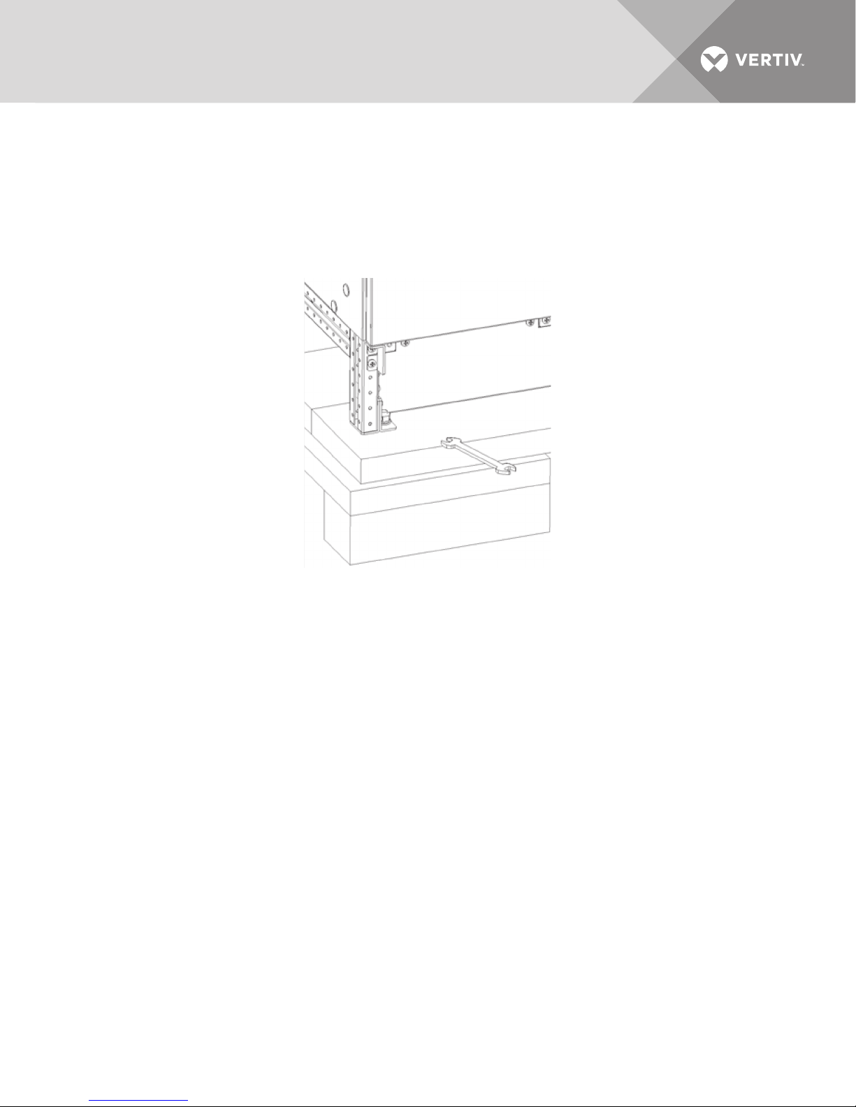
1.4.7 Unpacking and Unloading the Cabinet from the Pallet
The utmost care must be taken when removing the packaging to prevent damage to the equipment. Check all
packaging materials to ensure that no important items are discarded. Once the packaging has been removed,
the UPS must be taken off the pallet by removing the retaining screws, as illustrated in Figure 1, and lifting the
unit off using a fork lift Do not remove the retaining brackets securing the UPS to the pallet because they are
used to fasten the UPS to the floor, except where OSHPD compliance is required and the optional OSHPD
seismic anchoring kits are used.
Figure 1 Unpacking
1.5 SYSTEM COMPOSITION
A UPS system can comprise a number of equipment cabinets, depending on the individual system design
requirements: e.g., UPS cabinet, battery cabinet, maintenance bypass cabinet. In general, all the cabinets used in
a particular installation are of the same height. Refer to the drawings provided in 4.0 - Installation Drawings for
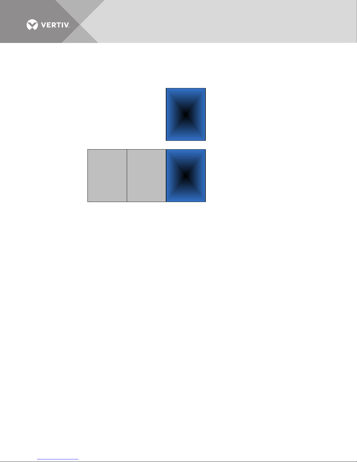
the positioning of the cabinets as shown in Figure 2.
Vertiv™| Liebert® NX™ 225-600kVA Installation Manual | Rev. 8 | 07/2017 7
Page 14
1.6 CABLE ENTRY
Liebert
NX
UPS
Liebert
NX
Battery
Cabinet
Liebert
NX
UPS
Additional
Liebert
NX
Battery
Cabinets
Battery Cabinets must
be installed on left of
UPS to wire internally
Cables can enter the UPS cabinet from bottom or top into the input/output (I/O) section of the unit; see the
figures in 4.0 - Installation Drawings.
Figure 2 Cabinet arrangement—Liebert NX matching battery cabinets
If the cabinets are to be bolted together, the side panels must be removed before beginning.
Vertiv™| Liebert® NX™ 225-600kVA Installation Manual | Rev. 8 | 07/2017 8
Page 15

2.0 UPS ELECTRICAL INSTALLATION
!
!
This chapter provides guidelines for qualified installers who must have knowledge of local wiring practices
pertaining to the equipment to be installed.
WARNING
Risk of electrical shock. Can cause injury or death.
The UPS contains high DC as well as AC voltages. Check for voltage with both AC and DC voltmeters
before working within the UPS.
Only properly trained and qualified personnel wearing appropriate safety headgear, gloves, shoes and
glasses should be involved in installing the UPS or preparing the UPS for installation.
2.1 EXTERNAL PROTECTIVE DEVICES
For safety, it is necessary to install circuit breakers in the input AC supply and external battery system. Given that
every installation has its own characteristics, this section provides guidelines for qualified installation personnel
with knowledge of operating practices, regulatory standards and the equipment to be installed.
External overcurrent protection must be provided. See Figure 14 for overload capacity.
2.2 POWER CABLES
The UPS requires both power and control cabling. All control cables, whether shielded or not, should be run
separately from the power cables in metal conduits or metal ducts that are electrically bonded to the metalwork
of the cabinets to which they are connected.
The cable design must comply with the voltages and currents in Ta bles 9 through 12, follow local wiring
practices and take into consideration the environmental conditions (temperature and physical support media),
room temperature and conditions of installation of the cable and system’s overload capacity (see 5.0 -
Specifications).
WARNING
Risk of electrical shock. Can cause injury or death.
Before cabling the UPS, ensure that you are aware of the location and operation of the external isolators
that connect the UPS input/bypass supply to the power distribution panel.
Check that these supplies are electrically isolated, and post any necessary warning signs to prevent their
inadvertent operation.
When sizing battery cables, a maximum volt drop of 2VDC is permissible at the current ratings given in Table 12.
The following are guidelines only and are superseded by local regulations and codes of practice where
applicable:
• The grounding conductor should be sized according to the fault rating, cable lengths, type of protection, etc. The
grounding cable connecting the UPS to the main ground system must follow the most direct route possible.
• Consideration should be given to the use of paralleled smaller cables for heavy currents, as this can ease installation
considerably.
• AC and DC cables must be run in conduits according to local codes, national codes and standard best practices. This will
prevent creation of excess EMI fields.
Vertiv™| Liebert® NX™ 225-600kVA Installation Manual | Rev. 8 | 07/2017 9
Page 16

2.3 SIZING THE INPUT BREAKER FEEDING A LIEBERT NX UPS
NOTE
See 3.2.3 - Capacity on Demand (Softscale) Upgrades.
Nominal input current (considered continuous) is based on full-rated output load. Maximum current includes
nominal input current and maximum battery recharge current (considered noncontinuous).
Continuous and noncontinuous current are defined in the NEC.
Maximum input current is controlled by the current limit setting, which is adjustable. Values shown are for
maximum current limit. If a smaller input feed breaker is used, the input current limit can be adjusted; see your
Vertiv representative for more information. The input current limit should not be set less than 105% of the
current needed to support the inverter at full load for normal operation.
This results in sufficient power to recharge the battery in a reasonable time and to operate over the published
input voltage range.
2.3.1 Single or Dual Input Feeds
The Liebert NX 225-600 kVA may be fed from single reference sources or dual asynchronous sources. If a
single-input configuration will be used, the utility source must be cabled to the rectifier input busbars. See
Figures 13 and 18.
2.3.2 Automatic Transfer Switches
If the UPS is to be fed from an automatic transfer switch, the transfer switch must have a programmed delay of
100 milliseconds for transfers between two sources.
Vertiv™| Liebert® NX™ 225-600kVA Installation Manual | Rev. 8 | 07/2017 10
Page 17
2.3.3 Power Cable Connection Procedure
!
!
!
The rectifier input, bypass, output and battery power cables (all require lug-type terminations) are connected to
busbars in the I/O sections (refer to 4.0 - Installation Drawings).
Equipment Ground
The equipment ground busbar is in the I/O sections as shown in (refer to 4.0 - Installation Drawings). The
grounding conductor must be connected to the ground busbar and bonded to each cabinet in the system.
All cabinets and cabling should be grounded in accordance with local regulations.
NOTE
Proper grounding reduces problems in systems caused by electromagnetic interference.
WARNING
Failure to follow adequate grounding procedures can result in electric shock hazard to personnel, or the
risk of fire, should a ground fault occur.
All operations described in this section must be performed by properly trained and qualified electricians
or technical personnel. If any difficulties are encountered, contact Vertiv. See the back page of this
manual for contact information.
Once the equipment has been positioned and secured, connect the power cables as described below (refer to
the appropriate cable connection drawing in 4.0 - Installation Drawings):
1. Verify that the UPS equipment is isolated from its external power source and all the UPS power isolators are open.
2. Check that these supplies are electrically isolated and post any necessary warning signs to prevent their inadvertent
operation.
3. Open exterior and interior panels on the front of the I/O sections.
4. Connect the ground to the equipment ground busbar located in the I/O sections.
5. Make power connections and tighten the connections to the proper torque.
Ensure correct phase rotation.
WARNING
Risk of electrical shock. Can cause injury or death.
If the load equipment will not be ready to accept power on the arrival of the commissioning engineer,
ensure that the system output cables are safely isolated at their termination.
WARNING
Risk of electrical shock. Can cause injury or death.
When connecting the cables between the battery extremities to the circuit breaker, always connect the
circuit breaker end of the cable first.
6. For control connection details, see 2.4 - Control Cable and Communication.
7. Close and secure the interior and exterior doors.
8. Attach the kick plates to the bottom of the unit.
NOTE
If the unit is to be installed in a position that does not permit access to rear kick plates, then the kick plates must
be installed before the unit is placed in its final position.
Vertiv™| Liebert® NX™ 225-600kVA Installation Manual | Rev. 8 | 07/2017 11
Page 18

2.4 CONTROL CABLE AND COMMUNICATION
Based on your site’s specific needs, the UPS may require auxiliary connections to manage the battery system
(external battery circuit breaker), communicate with a personal computer or provide alarm signaling to external
devices, or for Remote Emergency Power Off (REPO). Refer to Figures 9 and 15.
The Liebert NX is equipped with the following interfaces:
• XS3 - Slot for Liebert IntelliSlot™ or ManageUPS™ communication card
• XS6 - Slot for LIFE
•X3 - Reserved
• X6 - Serial interface for external LIFE Services
•XT1/2 - Not Used
•X9 - Reserved
• XT3/8 - 4-pole screw connector for REPO Input and REPO Status
•XT4 - Reserved
• TB1 - 16-pole screw connector for input contacts
• TB2 - 16-pole screw connector for output contacts
• X19A/B - 2x15-pole connectors for parallel UPS connection
• X20 - RJ-45 interface for synchronization with external signal
•XT1 - Not Used
• TB3 - Battery Interface and Key Status
• TB4 - SKRU Enable
2.4.1 Slot for Liebert IntelliSlot™ or ManageUPS™ Communication Cards—XS3
This slot is the interface for the Liebert network communication cards. This adapter provides an independent
external network interface for communication with network monitoring and building management systems.
™
Services modem
Units built since June 2016 are equipped with either the Liebert IntelliSlot system or the ManageUPS system.
Previous units included a factory-installed ManageUPS system, which provided connectivity to SNMP and
Modbus.
The Liebert IntelliSlot platform includes the Liebert IS-UNITY-DP™ and Liebert IS-485 EXI™ cards. The platform
communicates with Vertiv software tools and services, including Trellis®, Liebert SiteScan® Web and Liebert
Nform®.
The Liebert IS-UNITY-DP supports up to two third-party protocols along with HTTP/S (Web), Vertiv Protocol,
SMTP and SMS.
Third-party protocols available on the Liebert IS-UNITY-DP card are:
• BACnet IP—BACnet over Internet Protocol
• BACnet MSTP—BACnet Master-Slave/Token-Passing (MSTP) communications protocol over an RS-485 serial network
(also known as BACnet MSTP RS-485)
•Modbus RTU
•Modbus TCP
•SNMP versions 1, 2c and 3
NOTE
No more than two protocols may be enabled on one card.
Only one version of BACnet may be selected, either BACnet IP or BACnet MSTP.
Only one version of Modbus may be selected, either Modbus TCP or Modbus RTU.
Only one of the protocols can use the 485 port; choosing two 485 protocols will cause conflicts.
The Liebert IS-485 EXI Card connects to a Liebert SiteLink-E™, allowing Liebert SiteScan Web 4.0 monitoring
and control.
Vertiv™| Liebert® NX™ 225-600kVA Installation Manual | Rev. 8 | 07/2017 12
Page 19
Protocols available on the ManageUPS card, depending on the card model, are:
!
• Modbus RTU—Modbus Remote Terminal Unit (RTU) communication protocol over RS-232, RS-422 and RS-485
• Modbus TCP—Modbus Transmission Control Protocol over Internet Protocol (also known as Modbus TCP/IP)
•SNMP version 1
•Ethernet
•HTTP/Web
2.4.2 Slot for LIFE Services Products—XS6
This slot is the reserved interface for LIFE Services modem card. This card provides an independent external
modem interface for communication with LIFE Services service station. Ask your local Vertiv representative for
more details on LIFE Services and its benefits for your UPS system.
2.4.3 Serial Interface for Liebert LIFE Services Cards (Serial Input/Output)—X6
The service interface is a SUB-D nine-pin male connector for RS-232 serial communication. It is used for
communications with external LIFE Services or other special Liebert applications.
2.4.4 Connector for REPO (Input and Status)—XT3/8
This four-pole screw connector allows:
• Switching off the UPS from a remote source (e.g., push button)
• Providing status to an external system regarding whether the REPO is active
To perform a remote emergency power off, it is necessary to connect an emergency stop button to the UPS via a
shielded cable not exceeding 66ft. (20m) in length. The switch must be “Closed” under normal operating
conditions and be equipped with a mechanism that maintains it in the “Open” position after it has been pressed.
If this button is not installed, a jumper lead must be connected between Pins 1 and 2. For an indication of REPO
status, connect Pin 3 and Pin 4 to an external system.
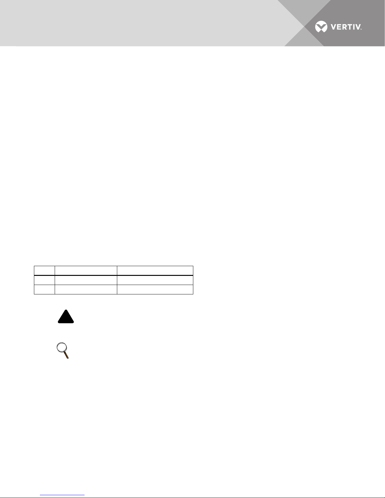
Table 1 REPO connection
Pin Signal Explanation
1 & 2 REPO Input Contact REPO active when open
3 & 4 REPO Status Contact Open when REPO is active
Use 16-22AWG cable.
WARNING
The external push button must be voltage free and isolated from all sources and GND. The external REPO
system must not exceed 24V and 20mA.
NOTE
The external EPO switch must latch open when activated.
Vertiv™| Liebert® NX™ 225-600kVA Installation Manual | Rev. 8 | 07/2017 13
Page 20
2.4.5 Customizable Output—TB2
!
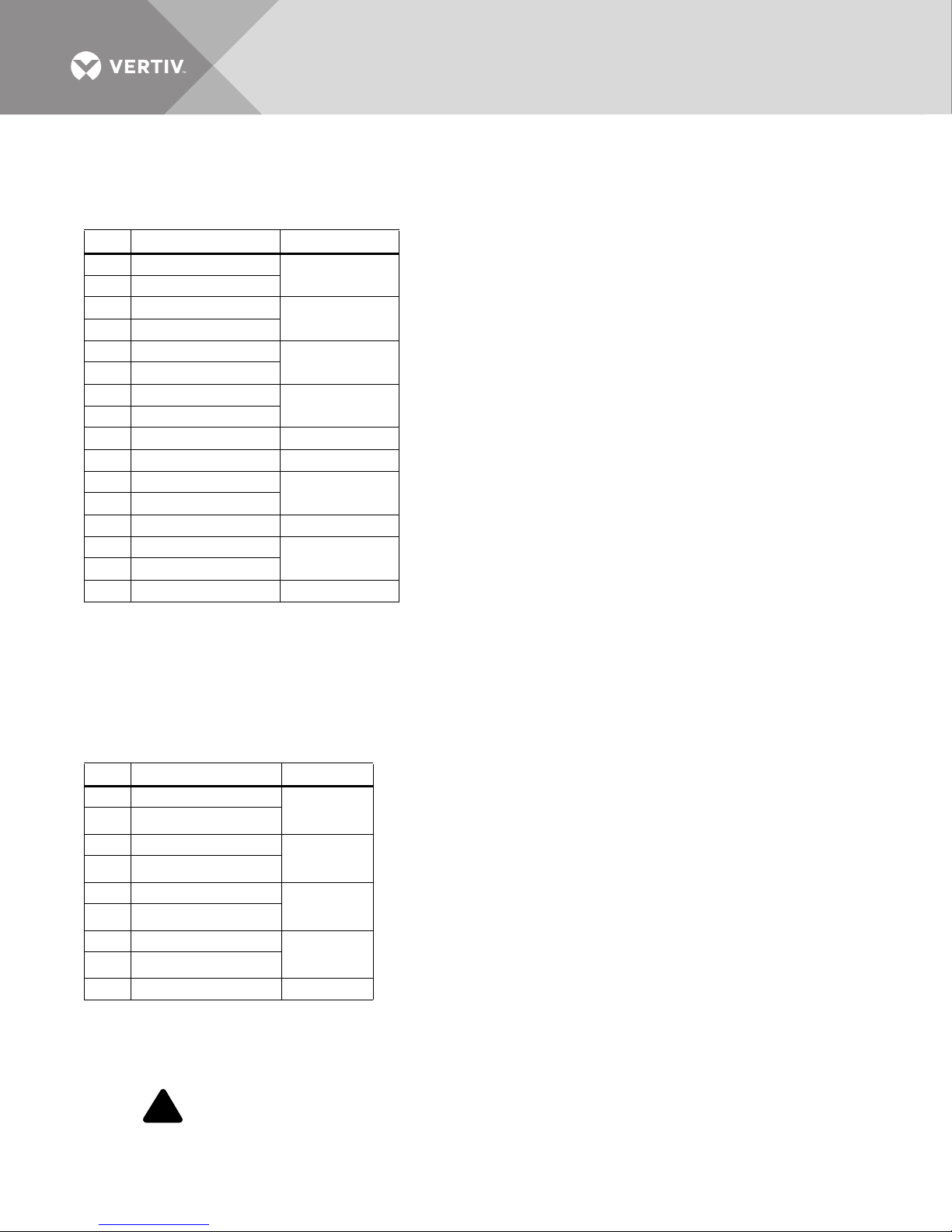
This 16-pole screw connector allows the connection of six individual configurable output contacts. Each contact
is rated for 24VDC 1A. The maximum potential difference between the pins must not exceed 24VDC.
Table 2 Customizable output contacts
Pin
Signal Explanation
1 Normally Closed
2 Normally Open
3 Normally Closed
4 Normally Open
5 Normally Closed
6 Normally Open
7 Normally Closed
8 Normally Open
9 Common Pins 1-8
10 Not Available
11 Normally Closed
12 Normally Open
13 Common Pins 11-12
14 Normally Closed
15 Normally Open
16 Common Pins 14-15
Alarm Summary
Bypass Active
Low Battery
AC Fail
Selectable
Selectable
Use 16-22AWG cable. The selectable contacts can be customized (by qualified technicians only) to perform
various functions.
2.4.6 Customizable Input Contact—TB1
This 16-pole screw connector allows the connection of four individual configurable input contacts.
Each contact is rated for 24VDC 1A. The maximum potential difference between the pins must not exceed 24VDC.
Table 3 Customizable input contacts
Pin
Signal Explanation
1 Input #1 (24VDC out)
2 Input #1 (24VDC signal)
3 Input #2 (24VDC out)
4 Input #2 (24VDC signal)
5 Input #3 (24VDC out)
6 Input #3 (24VDC signal)
7 Input #4 (24VDC out)
8 Input #4 (24VDC signal)
9-16 Common Pins 1-8 Not Available
1. This contact is used for the MBB auxiliary contacts. See Figure 5.
2. For 1+N systems, the auxiliary contacts for the MOB breaker must be connected to these inputs. See Figure 5. A shorting switch may be connected here for
Load Bank Breaker/Testing.
Selectable
Selectable
Selectable
Selectable
1
2
Use 16-22AWG cable. All input contacts can be programmed using service software.
WARNING
To drive the inputs, use no-voltage contacts. Do not use voltages supplied by external power supply.
Vertiv™| Liebert® NX™ 225-600kVA Installation Manual | Rev. 8 | 07/2017 14
Page 21
2.4.7 Contact Control for Eco Mode
An active economizer Eco Mode is enabled on the Liebert NX 225-600kVA UPS. The mode is incorporated in all
single-module systems and in multi-module (distributed bypass) units with Firmware Version 1.04 or newer.
For details on Eco Mode operation, refer to the Liebert NX operation manual, SL-25354, available at the Liebert
Web site: www.liebert.com. See Figures 20 and 21 for recommended wiring layout.
Eco Mode must be set up by an Vertiv Liebert Services customer engineer. Once set up, Eco Mode becomes the
default operating mode: It shifts the load to bypass if utility power is within specified limits and to
double-conversion (on-line) mode if utility power falls outside the limits.
The UPS can be set up so that Eco Mode can be activated and deactivated by the operator. A Liebert Services
engineer must program an input contact to suppress Eco Mode. A key switch or other device, supplied and
installed by others, can be used to provide the signal that deactivates Eco Mode to the input contact. Operating
the key switch (or other device) allows the UPS to return to Eco Mode as its default mode of operation. Contact
Liebert Services for details.
Additionally, a standby generator mode is available that may be activated by a contact closure (typically from the
generator). This mode shuts Off battery charging and brings the UPS out of Eco Mode while the generator is
providing the power.
2.4.8 Connector for Parallel UPS Connection—X19A, X19B
This interface is used for paralleling two or more UPS’s with each other.
2.4.9 RJ-45 Interface for Synchronization with External Signal—X20
This interface is used to communicate with an external synchronization device, such as Load Bus Sync Module
(for two modules only) or the Multibus Sync Module (for up to 11 modules). See the manuals related to these
options for more details.
The interface can be used to synchronize the outputs of multiple UPS devices, even when they do not have a
common output. This enables an external static switching device to commutate between UPS outputs in the
event of a malfunction, without creating synchronization problems.
2.4.10 UPS Control Contacts with Battery Cabinet or Module Battery Disconnect
These contacts are used to communicate between the UPS module and Battery cabinets or Module Battery
Disconnects.
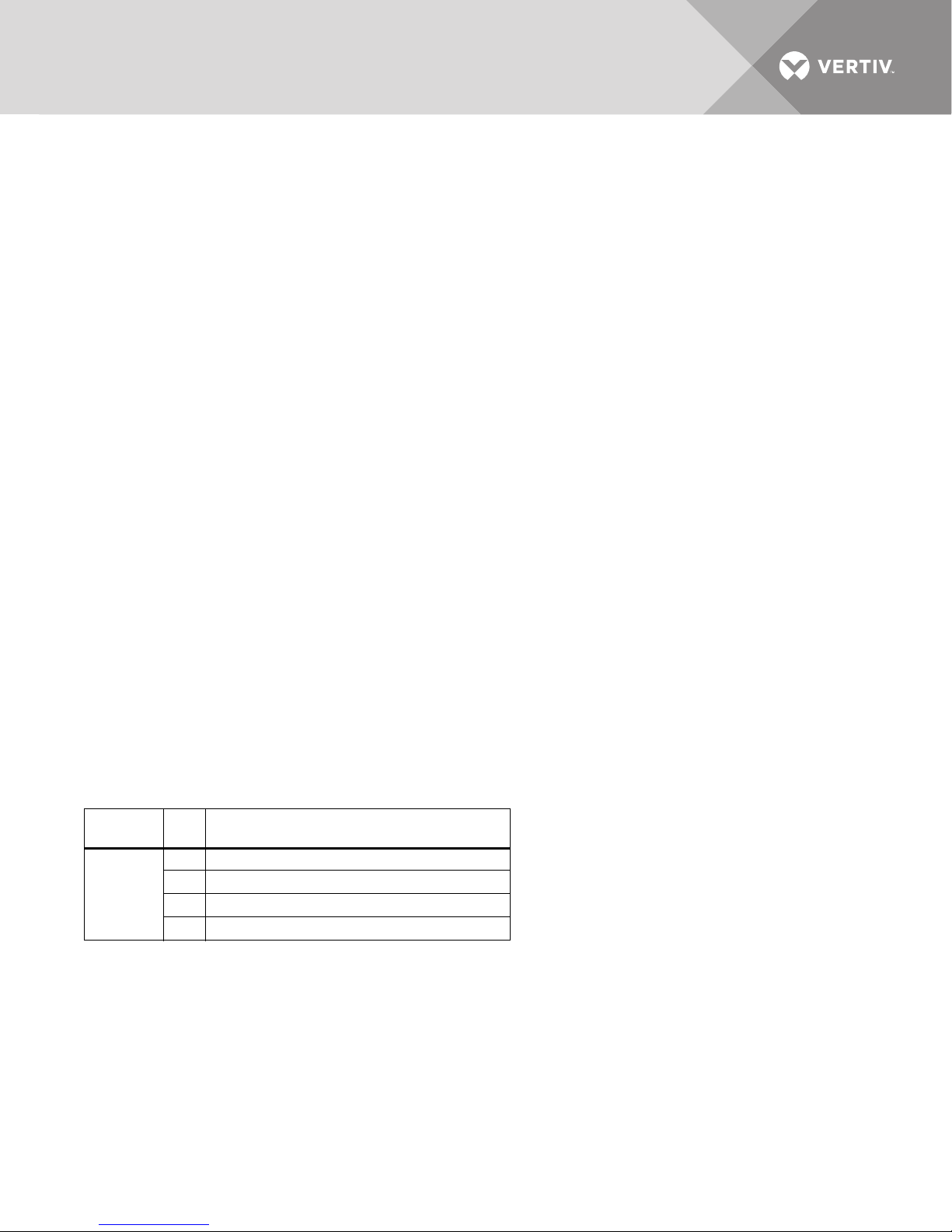
Table 4 Battery interface
Ter mi na l
Block Pin Connects to (Description of External Item)
1 Battery Interface Board TB1154-1
TB3
2 Battery Interface Board TB1154-2
3 Battery Interface Board TB1154-3
4 Battery Interface Board TB1154-4
Use Belden 9156 equivalent wire. Total length of cable from UPS to all battery interface connections must be less
than 1000ft (300m).
Vertiv™| Liebert® NX™ 225-600kVA Installation Manual | Rev. 8 | 07/2017 15
Page 22
2.4.11 UPS Control Contacts with Global Maintenance Bypass
!
These contacts are used to communicate between the UPS module and Maintenance Bypass.
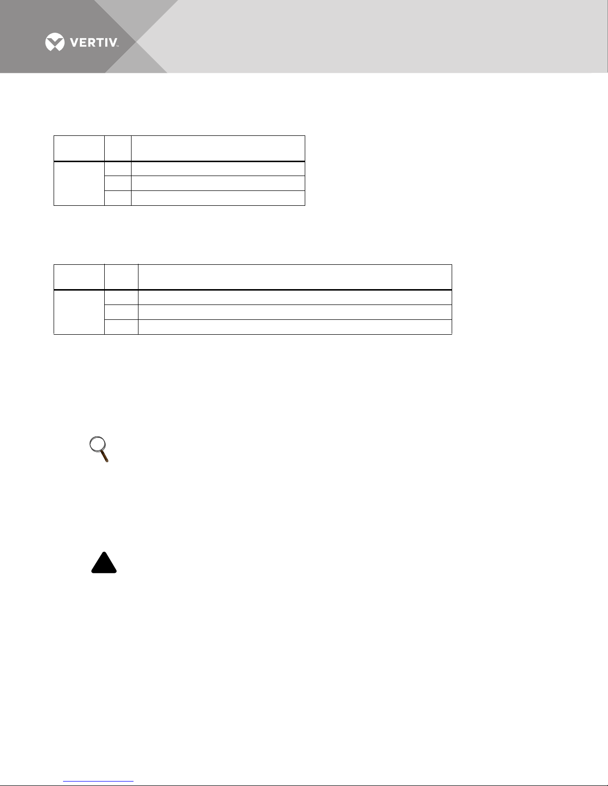
Table 5 Maintenance bypass key status
Ter mi na l
Block Pin Description
5 Key status switch, closed = key inserted
TB3
1. See 2.6 - Distributed Static Switch (1+N) System Cabling Layouts for 1+N systems with a Maintenance Bypass.
2. Key Status Input must be Form-C contact.
6 Key status switch, common
7 Key status switch, closed = key removed
Use 14AWG cable wire up to 500ft. (150m).
Table 6 Maintenance Bypass SKRU Enable
Ter mi na l
Block Pin Description
1 Maintenance Bypass Cabinet, closed = load not on inverter
TB4
1. For 1+N systems with a maintenance Bypass, these contacts must be run to each module from an isolated source.
2. These contacts must be run separately from all other control cables.
2 Maintenance Bypass Cabinet, common
3 Maintenance Bypass Cabinet, closed = load on inverter
Use 14AWG cable wire up to 500ft. (150m)
2.5 CONFIGURING GROUND CONNECTIONS
Liebert NX 225-600kVA is compatible with solidly grounded wye sources or a high resistance ground system, if
compatible. Refer to 2.5.3 - High-Resistance Ground Systems.
NOTE
Early production models may not be compatible with high-resistance ground systems.
Improper grounding is the largest single cause of UPS installation and startup problems. Grounding techniques
vary significantly from site to site, depending on several factors.
Proper grounding should be based on the appropriate NEC sections, but safe and proper equipment operation
requires further enhancements. The following pages detail recommendations for grounding various system
configurations to ensure optimal UPS system performance.
CAUTION
The UPS ground lug must be solidly connected to the service entrance ground by an appropriately sized
wire conductor per the NEC.
Each conduit or raceway containing phase conductors must also contain a ground wire, both for UPS
input and output, which are solidly connected to the ground terminal at each termination point.
Conduit-based grounding systems tend to degrade over time. Therefore, using conduit as a grounding
conductor for UPS applications may degrade UPS performance and cause improper UPS operation.
Vertiv™| Liebert® NX™ 225-600kVA Installation Manual | Rev. 8 | 07/2017 16
Page 23
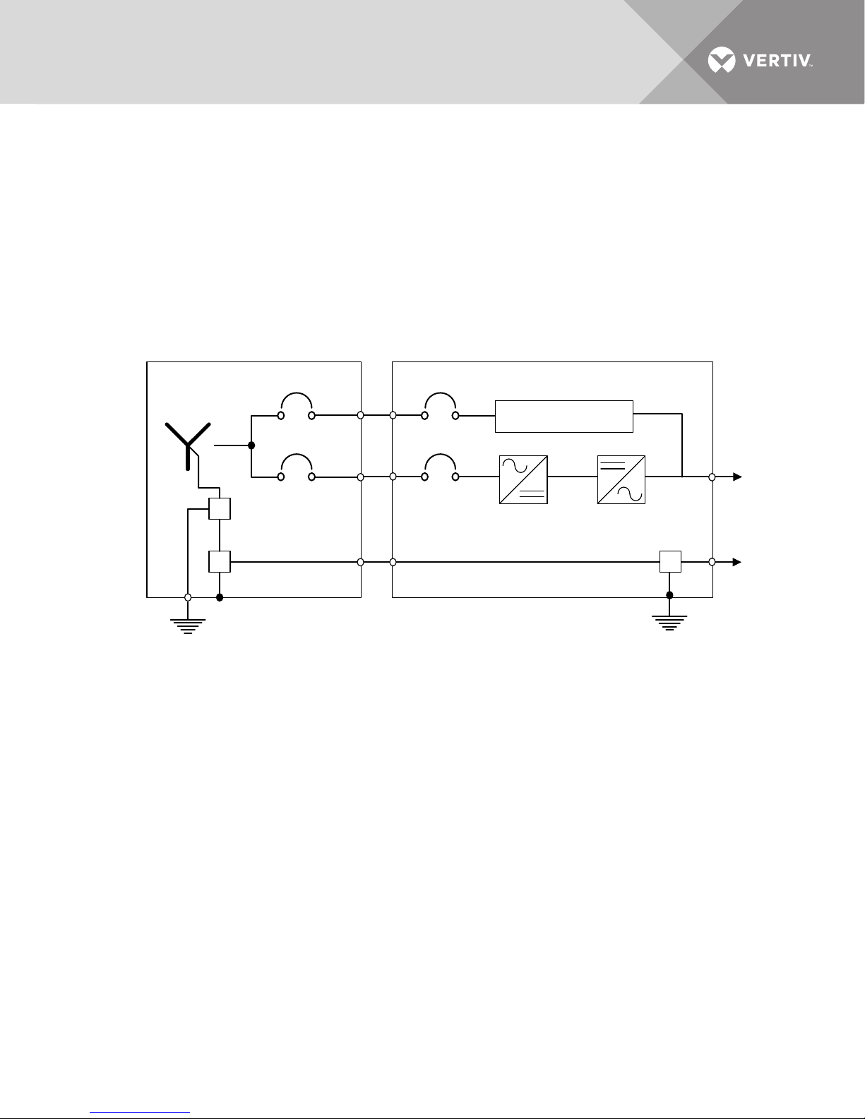
2.5.1 Three-Wire Input Connections
UPSSource
G
N
BPSS
To Connect Equipment
G
This configuration must NOT be used when single-phase loads are directly connected to the UPS. Please note
that whenever the UPS module transfers to or from bypass, two AC sources (UPS output and bypass) are briefly
connected together and circulating current must flow. In this configuration, the current flows through the ground
path, possibly tripping ground fault interrupters (GFI’s) and distorting the output voltage waveform. Proper
adjustment of ground fault interrupters is necessary to avoid unwanted tripping. The time delay should be set to
at least 0.2 seconds to prevent tripping when the UPS performs a transfer or retransfer operation.
NOTICE
Risk of improper installation. Can cause equipment damage.
Failure to set the ground fault interrupters properly could cause loss of power to the critical load.
Figure 3 Grounding diagram—Three-wire single-module systems
Vertiv™| Liebert® NX™ 225-600kVA Installation Manual | Rev. 8 | 07/2017 17
Page 24
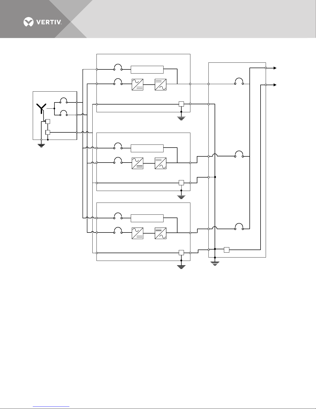
Figure 4 Grounding diagram—Three-wire multi-module systems
UPS
Source
G
N
BPSS
G
UPS
BPSS
G
UPS
BPSS
G
Switchgear
To connect equipment
G
2.5.2 Preferred Grounding Configuration, Battery Systems
Battery cabinet systems must be connected as floating (ungrounded) systems.
Center-tapped or grounded battery systems are not possible with battery cabinet systems.
Whether the battery system is open-rack or cabinet, the metal rack parts or cabinet must be grounded to the
UPS module ground bus.
Vertiv™| Liebert® NX™ 225-600kVA Installation Manual | Rev. 8 | 07/2017 18
Page 25

2.5.3 High-Resistance Ground Systems
Liebert NX 400-600kVA units produced on or after August 1, 2013, with serial numbers as indicated below, are
compatible with High Resistance Ground (HRG) applications. Earlier production units may NOT be compatible
with HRG application and may either bear no label or be specifically labeled as not compatible. If the Liebert NX
UPS is NOT labeled as either compatible or not compatible, contact the factory before installing the unit in an
HRG application.
Liebert NX Serial Numbers/Compatibility with High Resistance Ground
NX 225-600 kVA serial numbers are structured as follows:
21 XXXXXXXX 1 38 X XX XXXX
(Digits 12, 13 and 14 are underlined above)
Digits 12 and 13 of the serial number represent the year of production
Example—1 3 = calendar year 2013; 1 4 would represent calendar year 2014.
Digits 1 and 3 represent the month
Example—1-9 = January-September, A = October, B = November, C = December
(e.g. 1 38 = August 2013, 1 3C= December 2013)
HRG compatibility was instituted for Liebert NX 400-600kVA units effective August 1, 2013, so serial numbers
with Digits 12,13 and 14 of 1 38 or higher designate Liebert NX 400-600kVA units that have HRG compatibility.
Contact the factory for HRG compatibility for Liebert NX 225-300kVA units.
2.6 DISTRIBUTED STATIC SWITCH (1+N) SYSTEM CABLING LAYO UTS
The output switchboard for a 1+N system must be configured with one Module Output Circuit Breaker (MOB) for
each UPS module to be connected to that switchboard. The breaker must be equipped with auxiliary contacts
that will be monitored by the UPS so that interlocks will function properly and for the HMI to indicate the
bypassed status of the module. Vertiv recommends using magnetic or thermomagnetic breakers. If molded case
switches will be used, Vertiv recommends installing breakers without electronic trip units or to set the trip units
as follows:
• For 225-300kVA Modules: 2000A for 2 milliseconds
• For 400-600kVA Modules: 3000A for 2 milliseconds.
Vertiv™| Liebert® NX™ 225-600kVA Installation Manual | Rev. 8 | 07/2017 19
Page 26
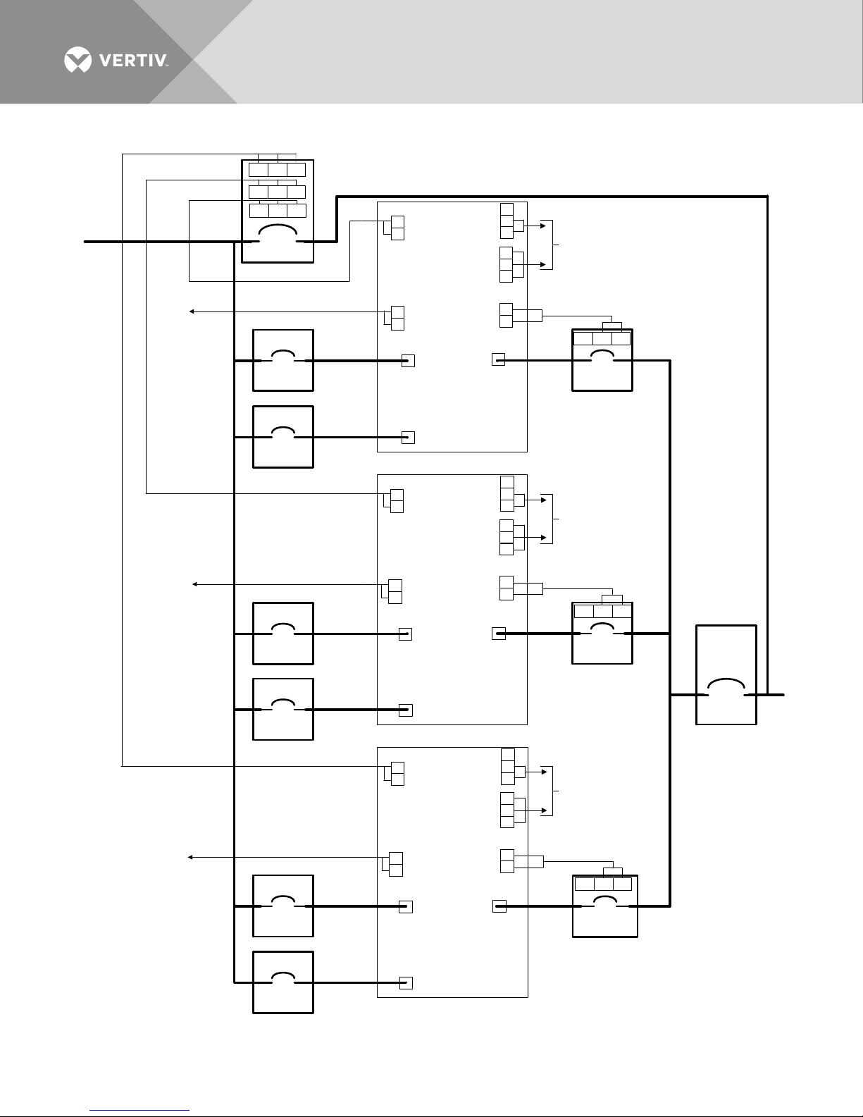
Input
Output
MBB
TB1
UPS 1
MOB1
MOB2
MOB3
RFB1
RFB3
BIB1
MBB
Source
Bypass
BIB3
BIB2
MIB
REPO Switch
(Optional)
RFB2
REPO Switch
(Optional)
1 2 3
5 6 73 4
1 2 1 2
REPO
XT3/8
MBE
TB4
Key Status
TB3
MOB
TB1
NC Com NO
UPS 2
Output
MBB
TB1
Bypass
REPO
XT3/8
Input
1 2
1 2
1 2 3
5 6 73 4
MBE
TB4
Key Status
TB3
MOB
TB1
NC Com NO
UPS N
See detai l
on SKRU
Connec tion
Page
Output
MBB
TB1
Bypass
REPO
XT3/8
Input
1 2
1 2
1 2 3
5 6 73 4
MBE
TB4
Key Status
TB3
MOB
TB1
NC Com NO
REPO Switch
(Opt ional)
NC Com NO
NC Com NO
NC Com NO
See detai l
on SKRU
Connec tion
Page
See detai l
on SKRU
Connec tion
Page
Figure 5 System layout, 1+N
Vertiv™| Liebert® NX™ 225-600kVA Installation Manual | Rev. 8 | 07/2017 20
Page 27
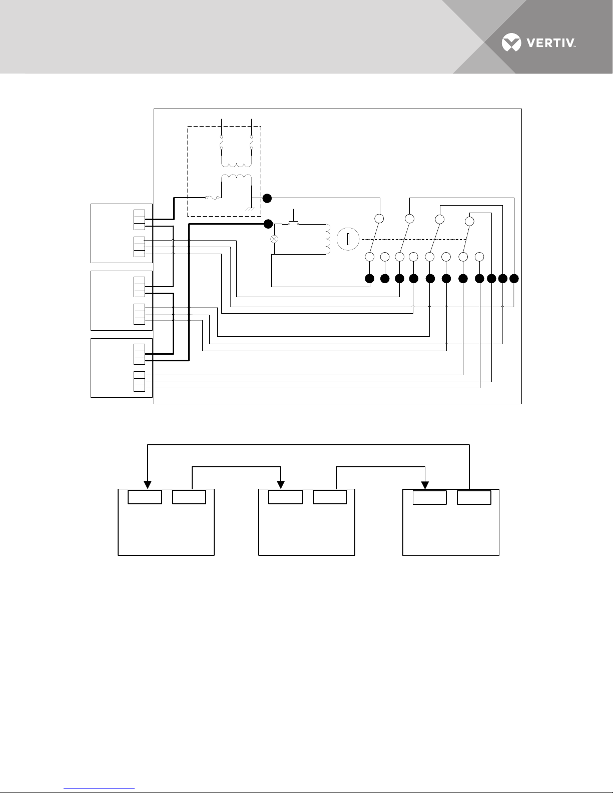
Figure 6 SKRU connections
UPS 1
MBE
TB4
Key Status
TB3
MBE
TB4
Key Status
TB3
MBE
TB4
Key Status
TB3
UPS 3
UPS 2
Switchgear or Panelboard Cabinet
Powered from Critical Bus
1
120VAC
Neutral
4
Transformer
provided by
others
Fuse
Fuse
Fuse
6 14
12
1198
Key
Push Button
for Key Release
Contact position shown
for key in captive
position.
7
1013
Lamp
3 5
Auxiliary contacts from the SKRU must be isolated.
3 65 8 9 11 12 14 13 10 7
1
4
1 2 35 6 71 2 31 2 3 5 6 75 6 7
UPS #1
X19/B X19/A
UPS #2
X19/B X19/A
UPS N
X19/B X19/A
Figure 7 Control wiring
Vertiv™| Liebert® NX™ 225-600kVA Installation Manual | Rev. 8 | 07/2017 21
Page 28
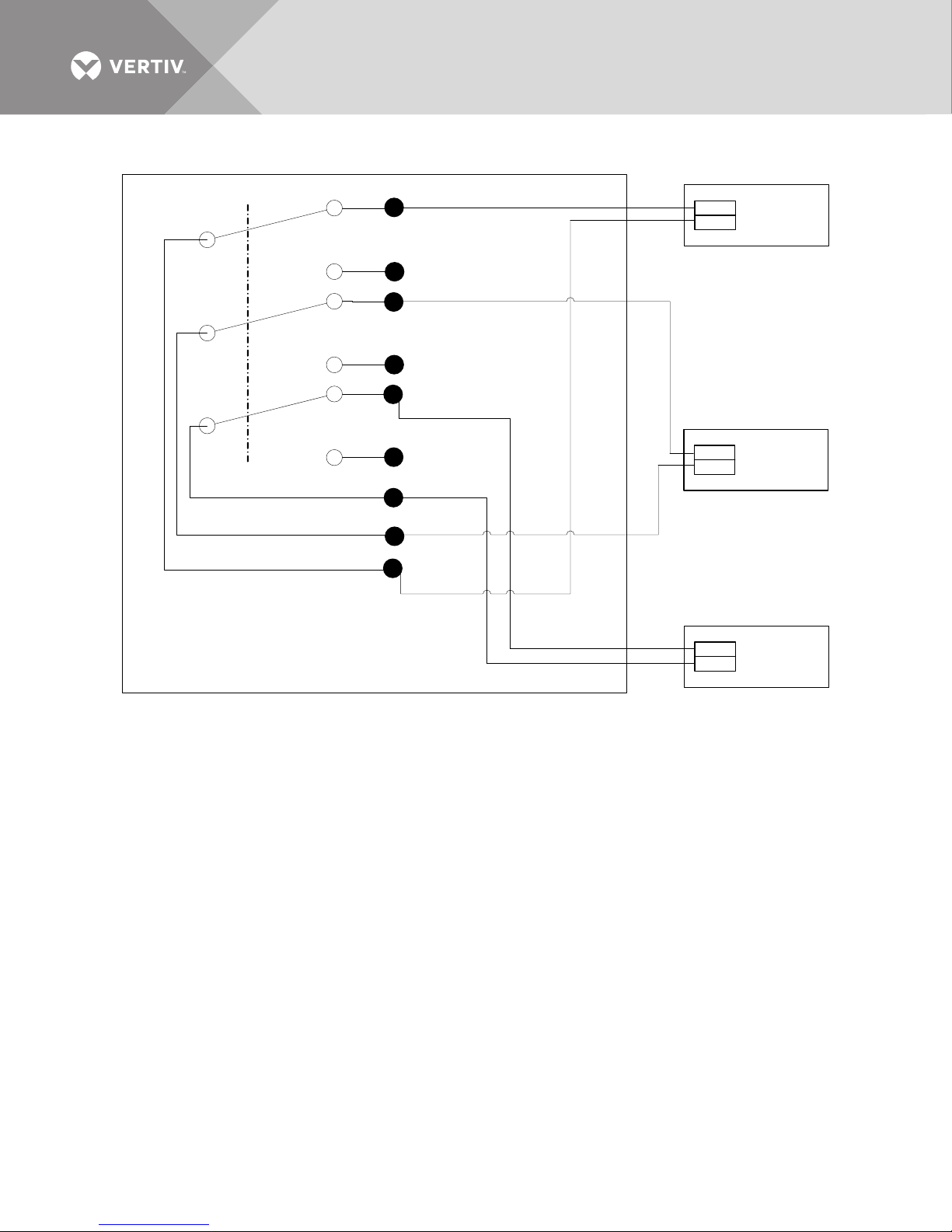
Figure 8 REPO connections 1+N system
REPO
XT3/8
12
REPO
XT3/8
12
REPO
XT3/8
12
UPS 1
Switchgear or Panelboard Cabinet
1 97643
REPO Relay Contacts
852
All auxilliary contacts from the REPO must be isolated.
UPS 2
UPS N
1
3
4 6
7
9
2
5
8
Vertiv™| Liebert® NX™ 225-600kVA Installation Manual | Rev. 8 | 07/2017 22
Page 29

3.0 OPTIONAL EQUIPMENT
3.1 SINGLE-MODULE SYSTEM OPTIONS
3.1.1 Input Circuit Breaker
The input circuit breaker, which feeds the rectifier, is a option because some configurations may not require this
if a maintenance bypass with a rectifier input breaker is located close to the UPS module
3.1.2 External Battery Temperature Sensor—Optional
For systems that do not use Liebert NX Battery Cabinets, an optional temperature sensor can be installed to
monitor the battery cabinet or ambient room temperature. This sensor is connected to the BIB board. This
sensor will allow the Liebert NX UPS to perform temperature compensation charging.
3.1.3 Matching Liebert NX Battery Cabinet
The optional matching Liebert NX Battery Cabinet can be used to obtain the desired autonomy time. The
battery cabinets are designed to be either attached to the UPS or separate from the UPS (for details, see the
Liebert NX Battery Cabinet installation manual, SL-25430, available at Liebert’s Web site: www.liebert.com)
3.1.4 Battery Interface Box
The battery interface box contains a battery interface board. The battery interface box is required when an NX
225-600kVA UPS is installed with any non-Liebert battery cabinet, non-matching MBD or Battery Isolation
Switch (BIS).
One battery interface box is required for each non-Liebert battery cabinet, MBD or BIS.
3.1.5 Local EPO Button
A local EPO button with protective cover is available. This option is typically installed at the factory but may be
field-installed by Liebert Services.
3.2 COMMUNICATION AND MONITORING
• Liebert IS-UNITY-DP™ card, supports any two of the following: BACnet IP; BACnet MSTP; Modbus RTU; Modbus TCP; and
SNMP versions 1, 2c and 3
•Liebert IS-485 EXI
• ManageUPS
3.2.1 Remote Status Panel
Available as surface mount. The power supply for the remote status panel is factory-installed in the UPS module
and must be ordered with the unit.
3.2.2 Alber Monitoring System
The matching Liebert NX Battery Cabinet allows installing an optional Alber® battery monitoring system in the
cabinet. The Alber battery monitoring by Liebert continuously checks all critical battery parameters, such as cell
voltage, overall string voltage, current and temperature. Automatic periodic tests of internal resistance of each
battery will verify the battery’s operating integrity.
Additional capabilities include automatic internal DC resistance tests and trend analysis, providing the ability to
analyze performance and aid in troubleshooting.
3.2.3 Capacity on Demand (Softscale) Upgrades
Modules that were ordered and installed as Capacity on Demand soft-scalable modules can be upgraded to
either full 300kVA/KW (from 225 or 250kVA/kW) or 600kVA KW(400 and 500kVA/kW). If this upgrade is
planned, breakers and conductors should be sized for the final capacity.
™
card connects to Liebert SiteLink-E for Liebert SiteScan® Web monitoring
™
card: SNMP v1, Ethernet, HTTP/Web; Modbus RTU and Modbus TCP.
Vertiv™| Liebert® NX™ 225-600kVA Installation Manual | Rev. 8 | 07/2017 23
Page 30

3.3 MULTI-MODULE SYSTEM OPTIONS AND ACCESSORIES
The accessories and options listed in sections 3.1 through 3.2.1 may be applied to the individual modules in a
multi-module (1+N) system or a synchronized dual bus (2N) system.
3.3.1 Paralleling Cable Kit
A DB-15 module-to-module communication cable is required for 1+N parallel systems. A kit with two cables, each
82ft. (25m) long, is available. At least one kit is required for each add-on UPS module; the number of kits required
is one fewer than the number of UPS modules in the 1+N system (e.g., six UPS modules would require five kits).
3.3.2 Load Bus Sync Controller
Distributes common reference synchronization signal for up to two Liebert NX 225-600 UPS modules. A typical
installation would have two modules synchronized to a common bypass line.
3.3.3 Multi-Bus Synch Module (MBSM)
This module is available to support up six or up to 11 UPS modules, and is generally configured to synchronize all
modules to a reference bus (e.g., bypass line). See the manual for this module for more details.
Vertiv™| Liebert® NX™ 225-600kVA Installation Manual | Rev. 8 | 07/2017 24
Page 31
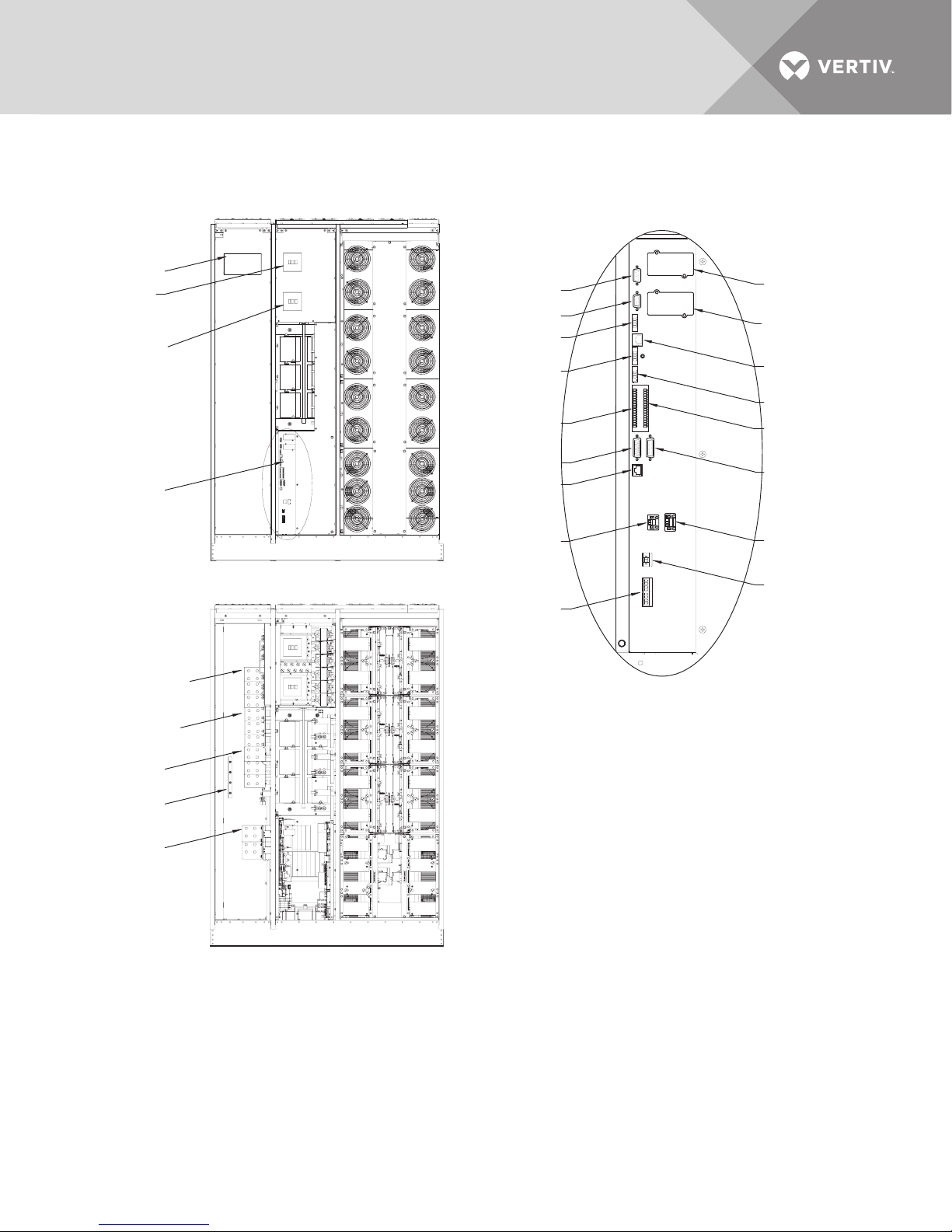
4.0 INSTALLATION DRAWINGS
Figure 9 Main components, 225-300kVA Liebert NX UPS, SMS and 1+N multi-module unit with static bypass
Control LCD
Main Input
Circuit Breaker
(CB1), optional
Backfeed Circuit
Breaker (BFB)
External
Communication
Panel, See Detail A
Bypass Busbars
Ø, A, B, C
Rectifier Input
Busbars Ø, A, B, C
Front Doors Removed
X3
X6
XT1/2
XT3/8
TB2
X19A
X20
XT2
(Non-Functional)
TB3
(See specific control wiring drawings)
XS3
XS6 (LIFE)
X9
XT4
TB1
X19B
XT1
(Non-Functional)
XB4
Detail A
External Communication Panel
Output Busbars
Ø, A, B, C
Input Ground
Busbar
Battery
Busbars (+ /-)
Doors and Inner Skins Removed
Vertiv™| Liebert® NX™ 225-600kVA Installation Manual | Rev. 8 | 07/2017 25
U38-3C-2000
Rev. 2
Page 32
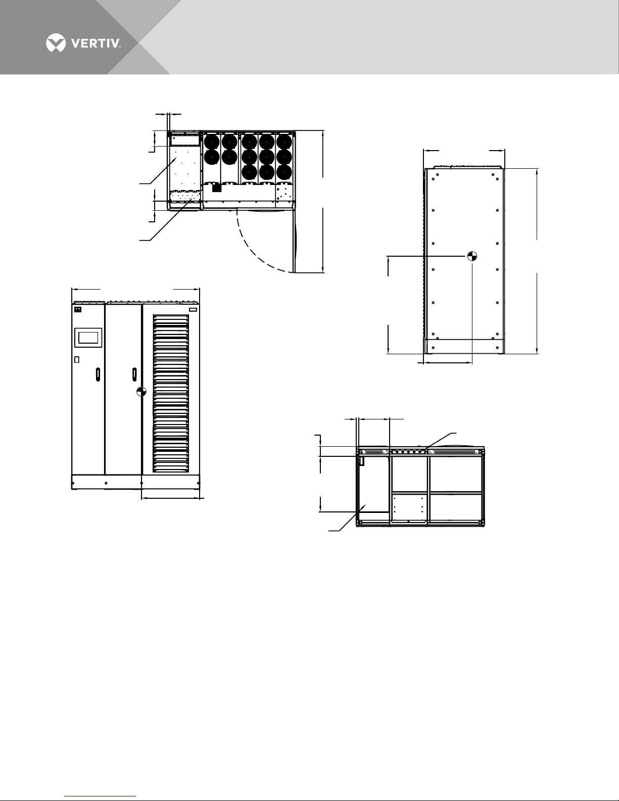
Figure 10 Outline drawing, 225-300kVA Liebert NX, SMS and 1+N multi-module unit with static bypass
NOTES
1. All dimensions are in inches (mm).
2. 24" (610) minimum clearance above unit required for air exhaust and 36" (914) front access
required for service.
3. Keep cabinet within 15 degrees of vertical.
4. Top and bottom cable entry available through removable access plates. Remove, punch to suit
cable entry size and replace.
5. Unit bottom is structurally adequate for forklift handling.
6. Control wiring and power wiring must be run in separate cable entry.
7. All wiring is to be in accordance with national and local electrical codes.
8. Depth dimension includes front door and rear panel.
9. Width dimensions include side panels.
10. See technical data drawing for shipping weights.
11. The height is to the top of the frame; fans rise 1.5" (38.1mm) above the frame.
76.8"
(1950mm)
See Note 12
FRONT
FRONT
FRONT VIEW
RIGHT SIDE VIEW
BOTTOM VIEW
Cable
Entry
12.8" (325mm)
23.1"
(586mm)
57.1"
(1450mm)
33.7"
(856mm)
53.4" (1357mm)
Center of
Gravity, Typ.
for Front
40.6" (1032mm)
20.2" (513mm)
Center of
Gravity
24.6" (616mm)
Center of
Gravity
1.1" (28mm) to Panel
1.1" (28mm)
to Panel
4.1"
(104mm)
to Panel
To Panel
6.5" (165mm)
To Panel
3.9" (99mm)
Conduit Plate
Low Voltage
Conduit Plate
3.8" x 12.7" (97 x 323) )
Power Conduit Plate
18.3" x 12.7"
(465 x 323)
U38-3C-2001
Rev. 4
Vertiv™| Liebert® NX™ 225-600kVA Installation Manual | Rev. 8 | 07/2017 26
Page 33
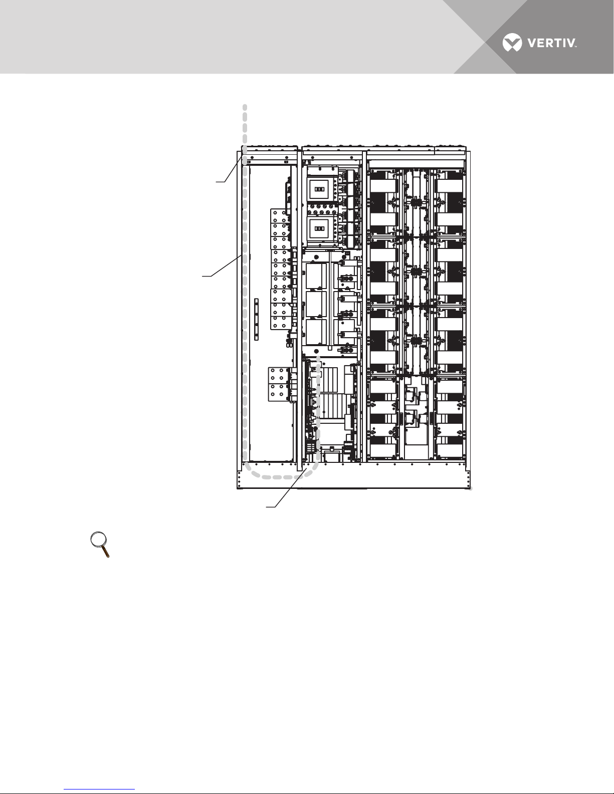
Figure 11 225-300kVA low-voltage cable routing
Low-Voltage
Top Entry
Top Entry,
Low-Voltage
Cable Raceway
Doors and
Inner Skins
Removed
NOTE
Remove the low-voltage control wire plate (at the top of the unit and then expose the area by removing the
inside cover plate), punch the conduit holes, land the conduit, and then route the control wire to the “chimney
stack” toward the bottom of the unit.
Run the control wires to through the conduit plate provided. If the unit is not on a raised floor, then insert a
rubber grommet into the conduit plate hole (at the bottom of the entry location for the low-voltage control
wiring).
Vertiv™| Liebert® NX™ 225-600kVA Installation Manual | Rev. 8 | 07/2017 27
Low-Voltage
Bottom Entry
Page 34
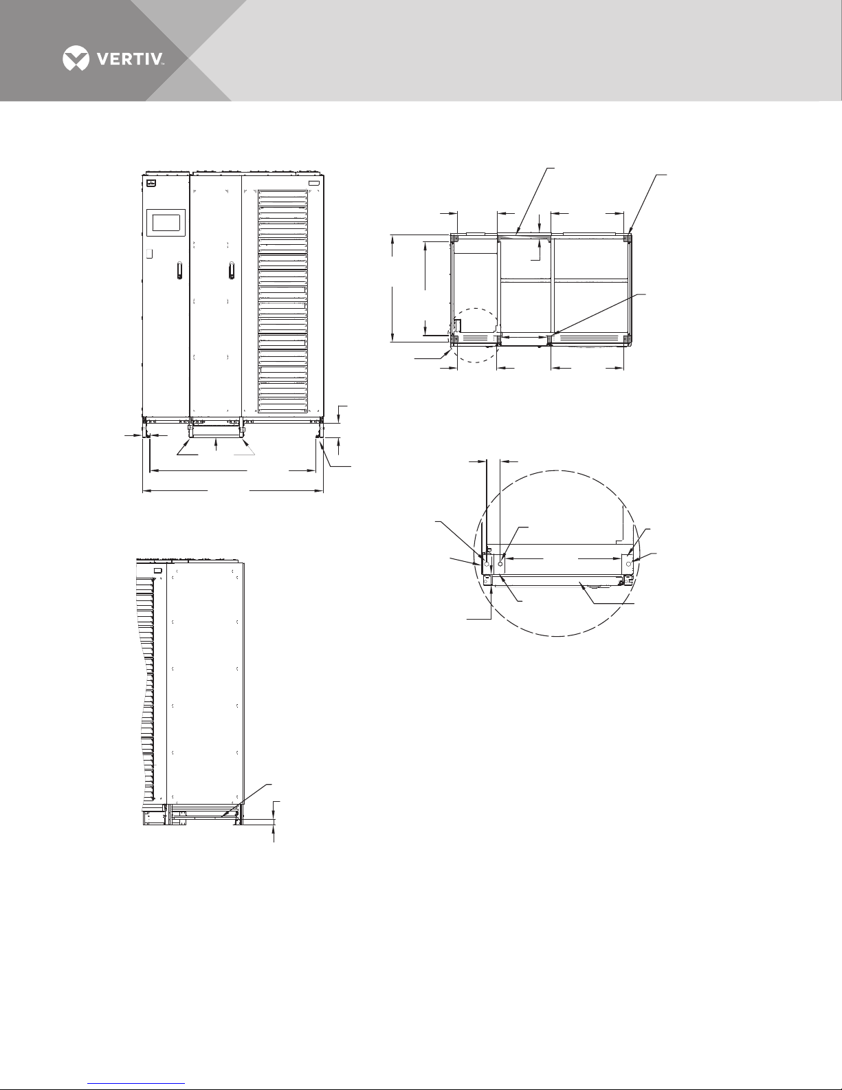
Figure 12 Base Drawing, 225-300kVA Liebert NX, SMS and 1+N multi-module unit with static bypass
Front
2.2" x 2"
(56mm x 50mm)
Pad, Typ. 4
Corners
11.5"
(291mm)
21.3"
(541mm)
13.8"
(350mm)
1.1" x 2"
(28mm x 50mm)
Pad, Typ. 2 places
11.6"
(296mm)
21.5"
(546mm)
15.6" x 1.1"
(397 x (27mm)
Pad
See
Detail A
BOTTOM VIEW
FOOTPRINT SPACING
Top View
11.5"
(291mm)
0.4"
[11]
Door
0.1" (2mm)
Pad to Outside
End Panel
1.1" (27mm)
Pad to Outside
Door Panel
DETAIL A
Pad
Pad
FRONT VIEW
WITHOUT KICKPLATE
2.2"
(56mm)
53.1"
(1350mm)
48.7"
(1238mm)
31.5"
(800mm)
27.6"
(700mm)
1.8"
(47mm)
Unit bottom is structurally adequate
for forklift handling front or rear only.
4.1"
(103mm)
Leg
1.7"
(42mm)
RIGHT ISOMETRIC VIEW
WITHOUT KICKPLATE
Rail
1.3"
(34mm)
Pad Dia. Centers
Pad
Pad
Ø 0.4"
(11mm)
Ø 0.3"
(8mm)
Vertiv™| Liebert® NX™ 225-600kVA Installation Manual | Rev. 8 | 07/2017 28
Page 35
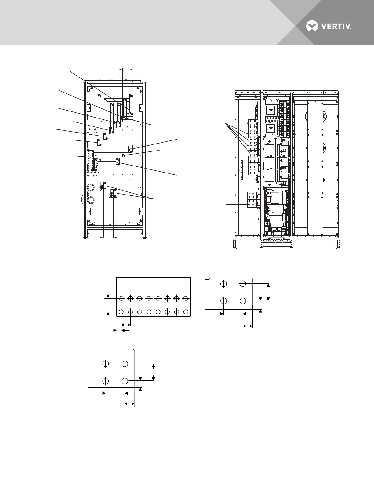
Figure 13 Terminal details, 225-300kVA Liebert NX, SMS and 1+N multi-module unit with static bypass
NOTE
See individual bus
detail drawings.
Front
ØA Bypass
Input
ØB Bypass
Input
ØC Bypass Input
ØC Input
ØB Input
ØA Input
Ground
FRONT
LEFT SIDE VIEW
ØA Output
See Bus Dwg 356
ØB Output
See Bus
Dwg 372
ØC Output
See Bus
Dwg 356
See Bus
Dwg 356
Ground
See Bus
Dwg 349
Batt Customer
Busbar See Bus
Dwg 370
See Bus
Dwg 372
Ø
0.6"
(15mm)
3.1" (78.7mm) Typ.
4.8"
(122mm)
NOTE
See individual bus detail drawings .
1.18" (30mm) Typ.
0.59" (15mm)
Typ.
Connection Busbar
0.63" (16mm)
Battery Busbar
0.87" (22mm)
1.75" (44.5mm)
1.97"
(50mm)
0.98" (25mm)
Input, Bypass,
Output Busbar
1.75" (44.5mm)
1.75" (44.5mm)
1.97"
(50mm)
0.98"
(25mm)
Figure 14 Terminal details Liebert NX 225kVA - 300kVA UPS 1+N multi-module or SMS
Vertiv™| Liebert® NX™ 225-600kVA Installation Manual | Rev. 8 | 07/2017 29
Page 36
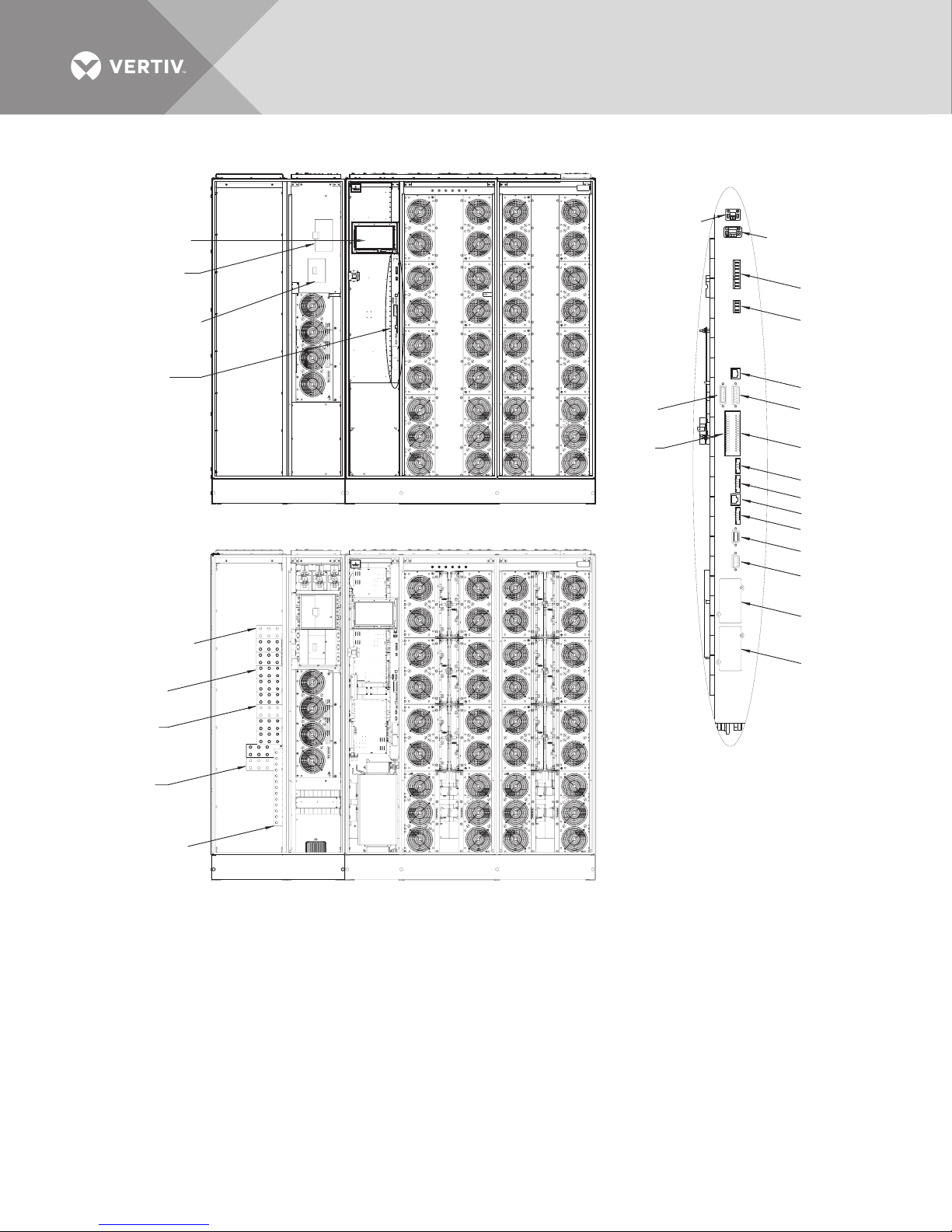
Figure 15 Main components, 400-600kVA Liebert NX UPS, SMS and 1+N multi-module unit with static bypass
Control LCD
Main Input
Circuit Breaker
(CB1), optional
Backfeed Circuit
Breaker (BFB)
External
Communication
Panel, See
Detail A
Bypass Busbars
Ø, A, B, C
Rectifier Input
Busbars Ø, A, B, C
Output
Busbars
Ø, A, B, C
Battery
Busbars (+ /-)
Input Ground
Busbar
Front Doors Removed
Doors and Inner Skins Removed
TB1
XT2
XT1
(Non-Functional)
TB3
TB4
X20
X19B
TB2
XT4
XT3/8
X9
XT1/2
X6
X3
XS3
XS6 (LIFE)
(Non-Functional)
X19A
Detail A
External Communication Panel
(See specific control
wiring drawings)
U38-6C-2000
Rev. 2
Vertiv™| Liebert® NX™ 225-600kVA Installation Manual | Rev. 8 | 07/2017 30
Page 37
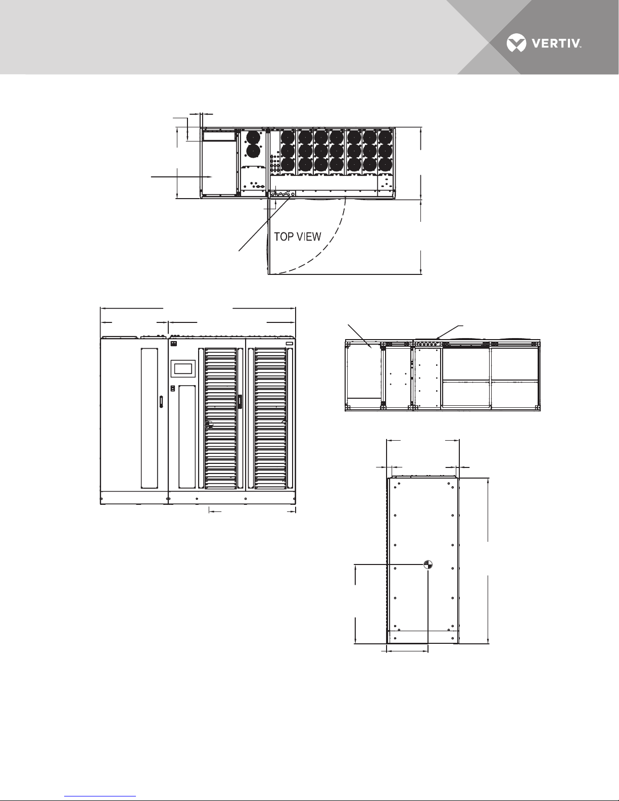
Figure 16 Outline drawing, 400-600kVA Liebert NX, SMS and 1+N multi-module unit with static bypass
6.5" (165mm)
to Panel
(844mm)
Power Conduit
Opening without Panel
24.5" x 15.5"
(622mm x 394mm)
90.7" (2304mm)
31.6"
(802mm)
1.1" (28mm) to Panel
VENT
33.2"
Low Voltage Conduit
Plate to Panel
1.3" (33mm)
Low Voltage
Conduit Plate
2.8" x 11.7"
(71mm x 297mm)
59.1" (1502mm)
Power Conduit
Opening without Panel
24.5" x 15.5"
(622mm x 394mm)
VENT
33.7"
(856mm)
34.7"
(881mm)
FRONT
Low Voltage
Conduit Plate
2.9" x 10.9"
(71mm x 276mm)
FRONT VIEW
1. All dimensions are in inches (mm).
2. 24" (610mm) minimum clearance above
unit required for air exhaust and 36" (914mm)
front access required for service.
3. Keep cabinet within 15 degrees of vertical.
4. Top and bottom cable entry available through removable
access plates. Remove, punch to suit cable entry size
and replace.
5. Unit bottom is structurally adequate for forklift handling.
6. Control wiring and power wiring must be run
in separate cable entry.
7. All wiring is to be in accordance with national
and local electrical codes.
8. Depth dimension includes front door and rear panel.
10. Width dimensions include side panels.
11. See technical data drawing for shipping weights.
11. The height is to the top of the frame; fans rise
1.5" (38.mm) above the frame.
40.2" (1022mm)
Center of Gravity
2.4"
(62mm)
FRONT
Center of Gravity
Typ. for Front
36.8" (935mm)
19.3" (489mm)
Center of
Gravity
U38-6C-2001
Rev. 5
BOTTOM VIEW
33.7"
(856mm)
29.8"
(756mm)
(38mm)
(1950mm)
See Note 12
RIGHT SIDE VIEW
1.5"
76.8"
Vertiv™| Liebert® NX™ 225-600kVA Installation Manual | Rev. 8 | 07/2017 31
Page 38
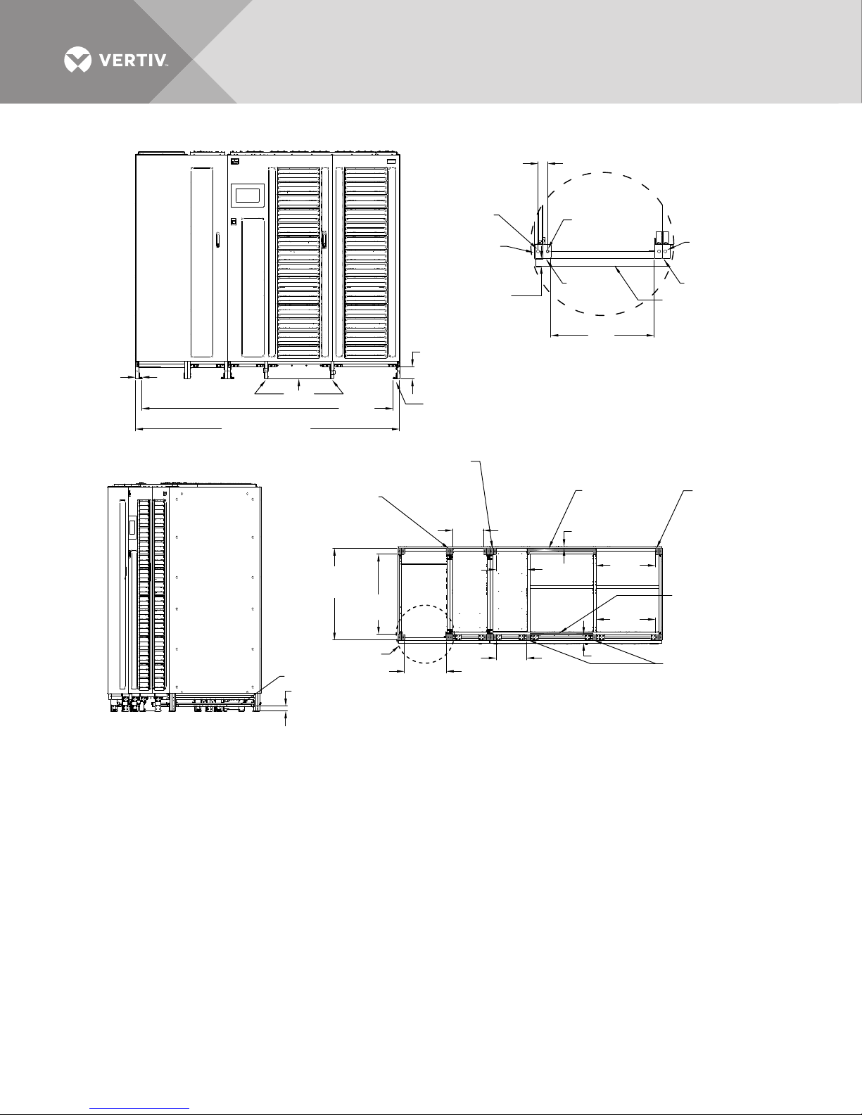
Figure 17 Base Drawing, 400-600kVA Liebert NX, SMS and 1+N multi-module unit with static bypass
BOTTOM VIEW
FOOTPRINT SPACING
Top View
Door
Pad
FRONT VIEW
WITHOUT KICKPLATE
Unit bottom is structurally adequate
for forklift handling front or rear only
RIGHT ISOMETRIC VIEW
WITHOUT KICKPLATE
4.1"
(103mm)
Leg
1.7"
(42mm)
Pad
Pad
2.2"
(56mm)
2.2" x 2"
(56mm x 50mm)
Pad, Typ.
Opposite Side
4.4" x 2"
(112mm x 50mm)
Pad, Typ.
Opposite Side
2.2" x 2"
(56mm x 50mm)
Pad, Typ.
4 Corners
23.5" x 1.1"
(597mm x 27mm)
Pad
1.1" (27mm)
Pad to Outside
Door Panel
0.1" (2mm)
Pad to Outside
End Panel
86.1"
(2188mm)
90.6" (2300mm)
Rail
See Detail A
FRONT
21.5" x .5"
(547mm x 13mm)
Pad
1.1" x 2"
(28mm x 50mm)
Pad, Typ. 2 Places
10.5"
(266mm)
10.7"
(271mm)
1.3"
(34mm)
14.4"
(366mm)
Ø 0.4"
(11mm)
Ø 0.4"
(11mm)
Typ.
Ø 0.3"
(8mm)
0.6" (15mm)
10.5"
(266mm)
20.5"
(521mm)
20.3"
(516mm)
14.4"
(366mm)
27.6"
(700mm)
31.5"
(800mm)
3" (76mm)
DETAIL A
Pad Dia. Centers
Pad
U38-6L-1000
Rev. 0
Vertiv™| Liebert® NX™ 225-600kVA Installation Manual | Rev. 8 | 07/2017 32
Page 39
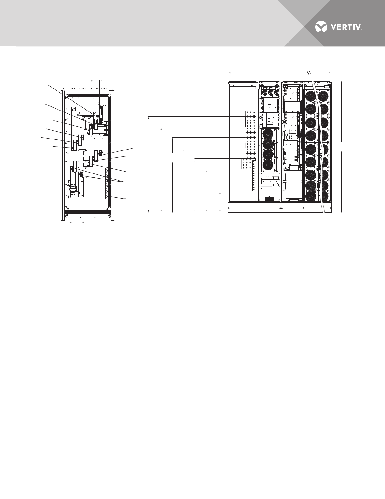
Figure 18 Terminal details, 400-600kVA Liebert NX, SMS and 1+N multi-module unit with static bypass
Battery
Customer
Busbar
FRONT
Ground
ØB
Output
ØC
Output
ØA
Output
ØA
Input
ØB
Input
ØC
Input
ØC
Bypass
Input
ØB
Bypass Input
ØA
Bypass Input
FRONT
78.3"
[1990mm]
12.9"
(326mm)
LEFT SIDE VIEW
3.1"v
(80mm) Typ.
25.8"
(656mm)
32.1"
(814mm)
38.3"
(972mm)
44.5"
(1130mm)
50.7"
(1288mm)
57"
(1448mm)
4.7" (120mm)
90.7"
[2304]
Vertiv™| Liebert® NX™ 225-600kVA Installation Manual | Rev. 8 | 07/2017 33
Page 40
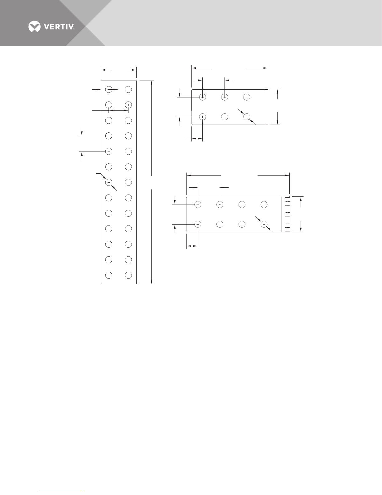
Figure 19 Terminal details Liebert NX 400kVA - 600kVA UPS 1+N multi-module or SMS
0.7"
(18mm)
1.8"
(44.5mm)
1.4"
(35mm)
3.2"
(80.3mm)
1.8"
(44.5mm)
1"
(25mm)
6.8" (173mm)
2"
(50mm)
(15mm) Typ.
INPUT, BYPASS,
OUTPUT BUSBAR
3.1"
80mm)
Ø 0.6"
Ø 0.6"
(15mm)
Typ.
18.1"
(460mm)
GROUND CONNECTION BUSBAR
1.8"
(44.5mm)
1"
(25mm)
9.2" (233mm)
2"
(50mm)
BATTERY BUSBAR
3.1"
80mm)
Ø 0.6"
(15mm) Typ.
Vertiv™| Liebert® NX™ 225-600kVA Installation Manual | Rev. 8 | 07/2017 34
Page 41
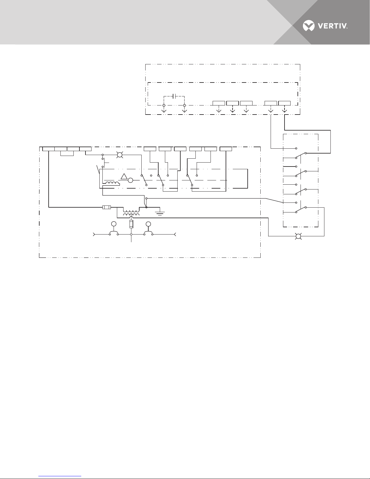
Figure 20 Recommended control wiring for Liebert NX 225-600kVA single module, Eco Mode
NX225-600kVA SMS
Contact closes when
UPS is on bypass
TB4-2 TB4-3
TB1-7
TB3-6 TB3-5
TB1-8
TB3-7
SKRU Status
(To SKRU 842, 840, 841)
(To SKRU 844, 843)
NO
2PDT SW
841
840
842
843844
821
823824
820
822
Solenoid Key Release
Unit (Auxiliary switch
shown in position with
key installed)
6
L
X
X
X
Maintenance
Bypass Source
MBB
MIB
Critical
Load
MAINTENANCE
BYPASS SWITCHBOARD
UPS
System
Source
ECO Mode
Enabled (On) Disabled (Off)
1. Key release unit with associated
controls and locking devices
supplied by switchboard provider.
2. Switchboard/gear manufacturer to
provide all wires, pins, sockets,
connectors and proper designation as shown.
3. All wiring to be UL/CSA approved.
4. Wire gauge to be #16 AWG minimum
except where noted.
5. All designated terminal blocks to
be accessible from the front of switchgear.
6. SKRU to be equipped with a two-pole,
double-throw (4P/DT) auxiliary switch.
7. 4PDT switch must be rated at 120VAC.
8. Switch position shown is for Eco-Mode disabled
U3826012
Rev. 0
Vertiv™| Liebert® NX™ 225-600kVA Installation Manual | Rev. 8 | 07/2017 35
Page 42
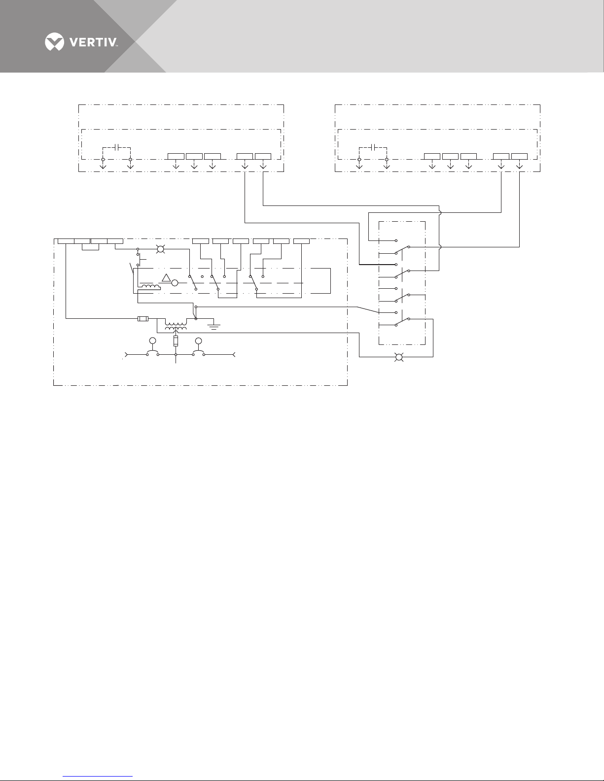
Figure 21 Recommended control wiring for Liebert NX 225-600kVA multi-module, Eco Mode
Liebert NX 1+N #2
Contact closes when
UPS is on bypass
Contact closes when
UPS is on bypass
TB4-2
TB4-3
TB4-2 TB4-3
TB1-7TB3-6 TB3-5 TB1-8TB3-7TB1-7TB3-6 TB3-5 TB1-8TB3-7
SKRU Status
SKRU Status
(To SKRU 842, 840, 841)
(To SKRU 822, 820, 821)
(To SKRU 844, 843)
(To SKRU 844, 843)
NO
NO
4PDT SW
841
840
842
843844 821823824
820
822
Solenoid Key Release
Unit (Auxiliary switch
shown in position with
key installed)
6
L
X
XX
Maintenance
Bypass Source
MBB
MIB
Critical
Load
MAINTENANCE
BYPASS SWITCHBOARD
UPS
System
Source
ECO Mode
Enabled (On) Disabled (Off)
1. Key release unit with associated
controls and locking devices
supplied by switchboard provider.
2. Switchboard/gear manufacturer to
provide all wires, pins, sockets,
connectors and proper designation as shown.
3. All wiring to be UL/CSA approved.
4. Wire gauge to be #16 AWG minimum
except where noted.
5. All designated terminal blocks to
be accessible from the front of switchgear.
6. SKRU to be equipped with a four-pole,
double-throw (4P/DT) auxiliary switch.
7. 4PDT switch must be rated at 120VAC.
8. Switch position shown is for ECO-Mode
disabled.
U3826011
Rev. 0
Liebert NX 1+N #1
Vertiv™| Liebert® NX™ 225-600kVA Installation Manual | Rev. 8 | 07/2017 36
Page 43
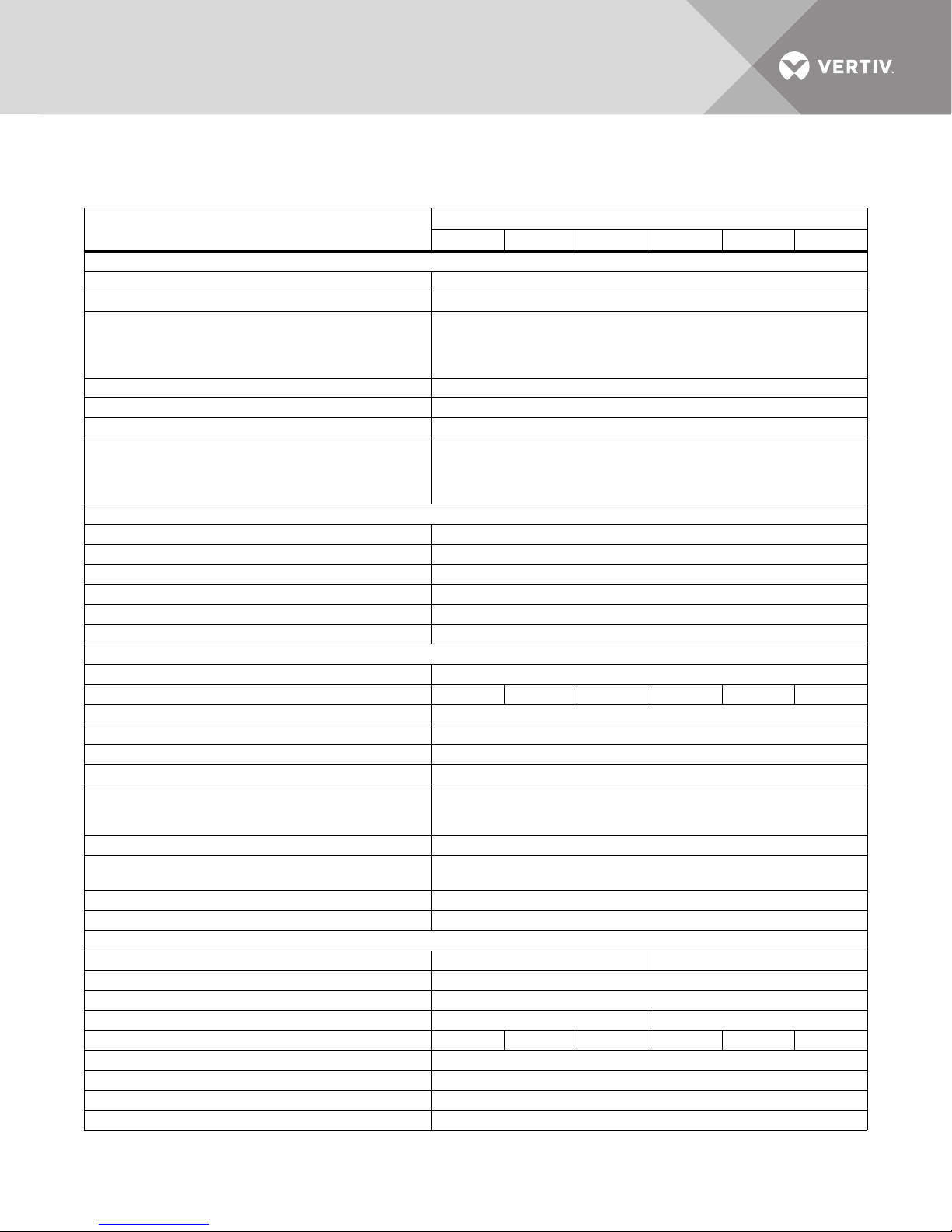
5.0 SPECIFICATIONS
Table 7 Liebert NX UPS specifications
Model Size
Input Parameters
Input Voltage to Rectifier, VAC 480V 3-phase, 3-wire
Input Voltage to Bypass, VAC 480V 3-phase, 3-wire
Input Voltage Range, VAC
Input Frequency, Hz 60
Permissible Input Frequency Range, Hz 55 to 65
Reflected Input THDi, Nominal Voltage, Full Load, % <5%
Power Walk-In, sec
Battery and DC Parameters
Battery Type VRLA (Valve Regulated Lead Acid) or FLA (Flooded Lead Acid)
Nominal Battery Bus, VDC 480V
Battery Float Voltage, VDC 540V
Minimum End of Discharge Voltage, VDC 396V (for VRLA / FLA)
DC Ripple Voltage in Float & Const V Ch. Mode, % <1 (RMS value) < 3.4% Vpp
Temperature Compensated Battery Charging Optional (with temperature probe)
Output Parameters
Inverter Type IGBT-based Sine-Sine PWM Controlled
Output Power, kW 225 250 300 400 500 600
Output Voltage, VAC 480V 3-ph, 3-wire
Output Voltage Regulation, % < 1% (3-phase RMS average)
Output Voltage Regulation (100% Unb. Load) < 2% (3-phase RMS average)
Output Frequency, Hz 60
Output Frequency Regulation
Output THDv Linear Load at Nominal Voltage, % <2
Output THDv at Nominal Voltage Including a 100kVA Non
Linear Load per EN 62040-3, %
Capacity to Handle High Crest Factor Load 3:1
Unbalance Loads Current Capacity 100% of nominal phase current
Physical Parameters and Standards, in (mm)
Width, With Static Bypass 53.4 (1356) 90.7 (2304)
Depth 33.7 (856)
Height 78.6 (1996)
Weight, Unpackaged, approximate, lb. (kg) 2,450 (1,110) 4450 (2019)
Maximum Heat Dissipation, Full Load, BTU/hr 41,000 45,000 54,000 72,000 90,000 108,000
Color Black (ZP-7021)
Front Door Opening (for serviceability) More than 90°
Degree of Protection for UPS Enclosure IP 20 (with and without front door open)
Minimum Clearance, Top, in (mm) 24 (610)
UPS Rating, kVA
225 250 300 400 500 600
+10% to -30%
(The UPS will operate at voltages down to -12.5% of nominal at 100% load
without discharging the battery. The UPS will operate without discharging the
battery at 70% of full nominal load with voltage down to -30% of nominal.)
1 to 90 (selectable) in 1 sec. Increments
(Walk-in begins after a 7-second source qualification time. Special settings
are available to permit shorter walk-in times for use with flywheels. Consult
factory for details.)
Synchronized to bypass: ±1.2 Hz (1.2Hz default setting, adjustable up to ±
3.6Hz by factory service personnel)
Synchronized to internal clock ±0.06Hz
2.5% (max)
Vertiv™| Liebert® NX™ 225-600kVA Installation Manual | Rev. 8 | 07/2017 37
Page 44
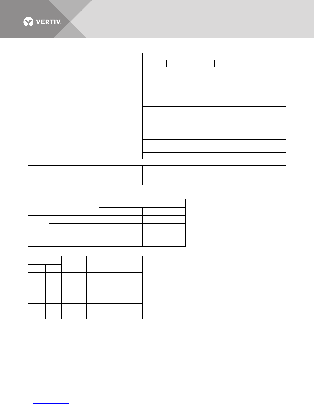
Table 7 Liebert NX UPS specifications (continued)
Model Size
Minimum Clearance, Back, in (mm) 0
Minimum Clearance, Sides, in (mm) 0
Location of Cable Entrance Top or Bottom
Standards and Conformities
Environmental Parameters
Storage Temperature Range, °F (°C) -13 to 158 (-25 to 70)
Operating Temperature Range, °F (°C) 32 to 104 (0 to 40) (UPS)
Relative Humidity 95% or less Non-Condensing (Operating and Non-Operating)
Table 8 UPS rating at altitude
UPS Rating, kW
Rating
vs.
Altitude
Altitude
up to 3300ft. (1000m) 225 250 300 400 500 600
up to 4921ft. (1500m) 225 250 270 400 500 540
up to 6562ft. (2000m) 225 250 252 400 500 504
up to 9842ft. (3000m) 225 225 225 400 450 450
225 250 300 400 500 600
UPS Rating, kVA
225 250 300 400 500 600
UL 1778, 5th Ed.
CSA 22.2 No. 107.3-14, 3rd Ed.
FCC Part 15, Class A
IEC62040-2, Level 4, Criteria A
EN61000-4-3, Level 3, Criteria A
EN61000-4-6, Level 4, Criteria A
EN61000-2-2, Criteria A
EN61000-4-4, Level 4, Criteria A
ANSI C62.41, Category A3 & B3
ISTA Procedure 1H
WEEE
Table 9 Current ratings—rectifier input
UPS Rating
225 225 480 285 299
250 250 480 317 332
300 300 480 380 399
400 400 480 505 530
500 500 480 632 663
600 600 480 761 799
Voltage
VAC
Nominal
Current
Maximum
Current kVA kW
Vertiv™| Liebert® NX™ 225-600kVA Installation Manual | Rev. 8 | 07/2017 38
Page 45
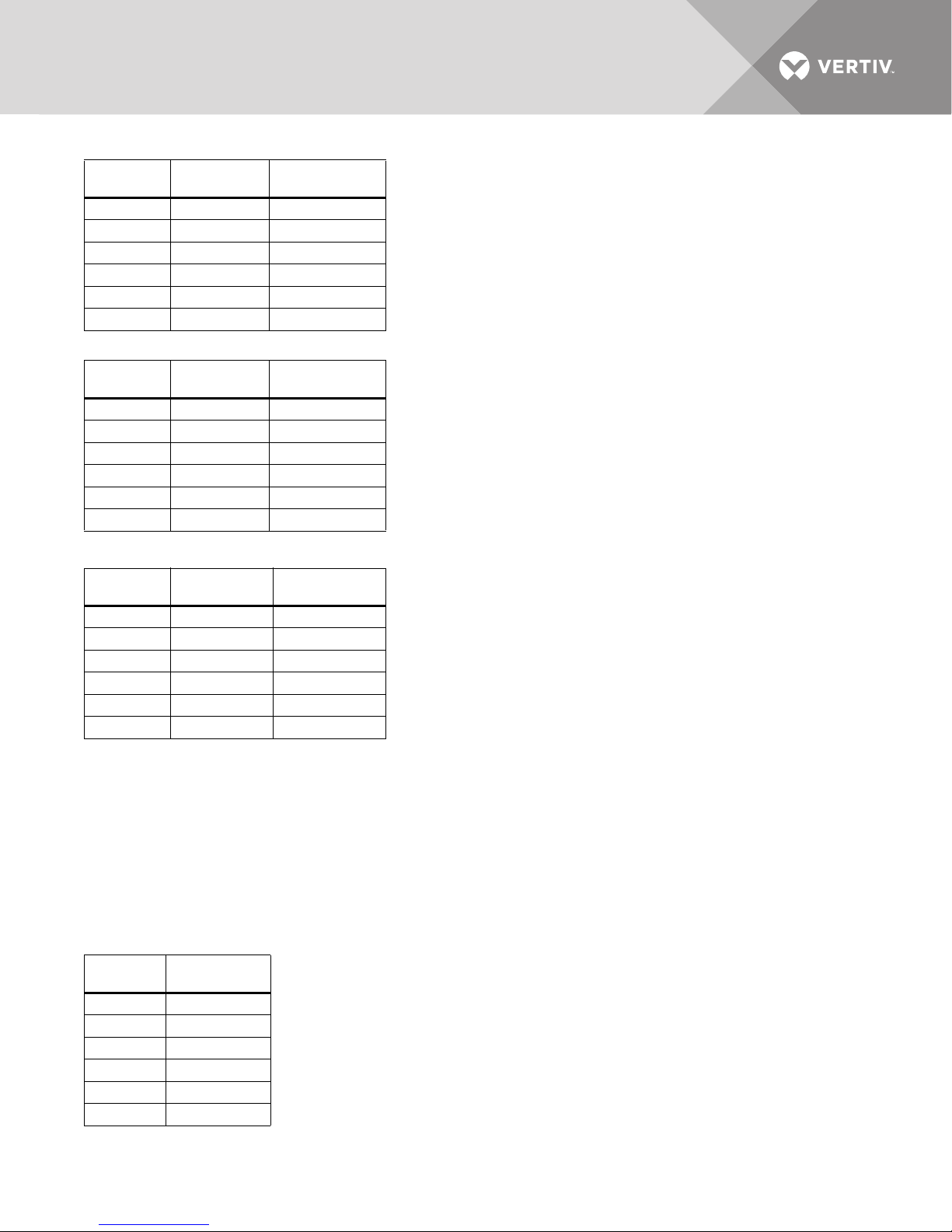
Table 10 Current ratings—bypass
UPS Rating
kVA/kW Voltage, VAC Nominal Current
225 480 271
250 480 301
300 480 361
400 480 481
500 480 601
600 480 722
Table 11 Current ratings—output
UPS Rating
kVA/kW Voltage, VAC Nominal Current
225 480 271
250 480 301
300 480 361
400 480 481
500 480 601
600 480 722
Table 12 Current ratings—battery
UPS Rating
kVA/kW Nominal VDC
225 480 600
250 480 667
300 480 800
400 480 1068
500 480 1335
600 480 1600
Maximum
Battery Current
Notes on Tables
1. Nominal input current (considered continuous) is based on full-rated output load. Maximum current includes nominal
input current and maximum battery recharge current (considered non-continuous). Continuous and non-continuous
current are defined in NEC 100.
2. For breaker coordination while the module is overloaded, see the current-versus-time values on the overload curves.
3. Nominal battery voltage is shown at 2.0 volts/cell.
4. Maximum Battery current at End of Discharge level of 1.65 volts per cell.
5. External DC Circuit Overcurrent Protective Device—Caution: To reduce the risk of fire, connect only to a circuit with the
maximum branch circuit overcurrent protection recommended in Tab le 1 3 in accordance with the National Electric Code,
ANSI/NFPA 70.
Table 13 Recommended DC circuit breaker rating
UPS Rating
kVA/kW
225 600
250 700
300 800
400 1200
500 1600
600 1600
Vertiv™| Liebert® NX™ 225-600kVA Installation Manual | Rev. 8 | 07/2017 39
Circuit Breaker
Rating, A
Page 46
Table 14 Current-versus-time curves of overload capacity
Overload Time, sec. (min.)
Load, %
101 8249.9 (137.5) 10,999.8 (183.3) 13,749.8 (229.2) 16,499.7 (275) 16,499.7 (275)
105 1650.0 (27.5) 2200.0 (36.7) 2750.0 (45.8) 3299.9 (55) 3299.9 (55)
110 825.0 (13.75) 1100.0 (18.3) 1375.0 (22.9) 1650.0 (27.5) 1650.0 (27.5)
115 550.0 (9.2) 733.3 (12.2) 916.7 (15.3) 1100.0 (18.3) 1100.0 (18.3)
120 412.5 (6.9) 550.0 (9.2) 687.5 (11.5) 825.0 (13.8) 825.0 (13.8)
125 319.4 (5.3) 425.9 (7) 532.4 (8.9) 638.9 (10.6) 638.9 (10.6)
130 222.2 (3.7) 296.3 (4.9) 370.3 (6.2) 444.4 (74) 444.4 (74)
135 152.7 (2.5) 203.6 (3.4) 254.6 (4.2) 305.5 (5) 305.5 (5)
140 100.6 (1.7) 134.2 (2.2) 167.7 (2.8) 201.3 (3.4) 201.3 (3.4)
145 36.7 (—) 48.9 (—) 61.1 (1.0) 73.3 (1.2) 73.3 (1.2)
150 27.7 (—) 37.0 (—) 46.2 (—) 55.4 (—) 55.4 (—)
155 7.3 (—) 9.7 (—) 12.1 (—) 14.6 (—) 14.6 (—)
160 7.3 (—) 9.7 (—) 12.1 (—) 14.5 (—) 14.5 (—)
165 7.3 (—) 9.7 (—) 12.1 (—) 14.5 (—) 14.5 (—)
The inverter overload is based on 104°F (40°C) ambient. At lower ambient temperatures, the overload timers automatically adjust to
longer run times.
104°F (40°C) 95°F (35°C) 86°F (30°C) 77°F (25°C) 60°F (20°C)
Vertiv™| Liebert® NX™ 225-600kVA Installation Manual | Rev. 8 | 07/2017 40
Page 47
Table 15 Recommended conduit and cable sizes
Rectifier Input
UPS Rating
kVA kW Copper Conductors Aluminum Conductors
225 225 480 (1) 2.5C 3-500kcmil, #4AWG (1) 2.5C 3-700kcmil, #2AWG
250 250 480 (1) 3.0C 3-600kcmil, #3AWG (2) 2.0C 3-300kcmil, #1AWG
300 300 480 (2) 2.0C 3-250kcmil, #3AWG (2) 2.0C 3-350kcmil, #1AWG
400 400 480 (2) 2.5C 3-500kcmil, #1AWG (2) 2.5C 3-600kcmil, #2/0AWG
500 500 480 (2) 3.0C 3-600kcmil, #1/0AWG (3) 2.5C 3-500kcmil, #3/0AWG
600 600 480 (3) 2.5C 3-500kcmil, #1/0AWG (3) 2.5C 3-600kcmil, #3/0AWG
Bypass Input
UPS Rating
kVA kW Copper Conductors Aluminum Conductors
225 225 480 (1) 2.5C 3-500kcmil, #4AWG (1) 2.5C 3-600kcmil, #2AWG
250 250 480 (1) 2.5C 3-500kcmil,#3AWG (1) 3.0C 3-750kcmil, #1AWG
300 300 480 (2) 1.5C 3-#4/0AWG, #3AWG (2) 2.0C 3-300kcmil, #1AWG
400 400 480 (2) 2.0C 3-350kcmil, #2AWG (2) 2.5C 3-500kcmil, #1/0AWG
500 500 480 (2) 2.5C 3-500kcmil, #1/0AWG (2) 3.0C 3-750kcmil, #3/0AWG
600 600 480 (2) 3.0C 3-750kcmil, #1/0AWG (3) 2.5C 3-500kcmil, #3/0AWG
Vol tage
(VAC)
Vol tage
(VAC)
(# of conduits); size of conduits; # -size of phase cables per conduit; size of cable
for ground per conduit
(# of conduits); size of conduits; # -size of phase cables per conduit;
size of cable for ground per conduit
Output
UPS Rating
kVA kW Copper Conductors Aluminum Conductors
225 225 480 (1) 2.5C 3-500kcmil, #4AWG (1) 2.5C 3-600kcmil, #2AWG
250 250 480 (1) 2.5C 3-500kcmil,#3AWG (1) 3.0C 3-750kcmil, #1AWG
300 300 480 (2) 1.5C 3-#4/0AWG, #3AWG (2) 2.0C 3-300kcmil, #1AWG
400 400 480 (2) 2.0C 3-350kcmil, #2AWG (2) 2.5C 3-500kcmil, #1/0AWG
500 500 480 (2) 2.5C 3-500kcmil, #1AWG (2) 3.0C 3-750kcmil, #3/0AWG
600 600 480 (2) 3.0C 3-750kcmil, #1AWG (3) 2.5C 3-500kcmil, #3/0AWG
Battery (Copper Conductors Only for Battery)
UPS Rating
kVA kW
225 225 480 (2) 2C 2-500kcmil, #1/0AWG
250 250 480 (2) 2C 2-600kcmil, #1/0AWG
300 300 480 (2) 2.5C, 2-600kcmil, #2/0AWG
400 400 480 (3) 2.5C, 2-600kcmil, #3/0AWG
500 500 480 (3) 2.5C, 2-750kcmil, #4/0AWG
600 600 480 (5) 2.5C, 2-600kcmil; 250kcmil
1. Recommended cable sizes are 167°F (75°C) (THW) wire at 86°F (30°C) ambient.
2. For continuous operations not at 86°F (30°C), Vertiv recommend that the site planner choose the appropriate cable type based on the particular installation
requirements.
3. Recommended conduit is based on FMC type conduit.
Vol tage
(VAC)
Vol tage
(VAC)
(# of conduits); size of conduits; # -size of phase cables per conduit;
size of cable for ground per conduit
(# of conduits); size of conduits; # -size of phase cables per conduit;
size of cable for ground per conduit
Copper Conductors
Vertiv™| Liebert® NX™ 225-600kVA Installation Manual | Rev. 8 | 07/2017 41
Page 48
Table 16 Recommended lug sizes
Cable Size
#8AWG 54930BE 54850BE 60104-TB —
#6AWG 54905BE 256-30695-868 60109-TB —
#4AWG 54906BE 256-30695-733 60114-TB —
#2-3AWG 54942BE 54811BE 60120 —
#1AWG 54947BE 54857BE 60126 —
#1/0AWG 54950BE 256-30695-593 60132 —
#2/0AWG 54951BE 54862BE 60138 60238
#3/0AWG 54965BE 54864BE 60144 60244
#4/0AWG 54970BE 54866BE 60150 60250
250kcmil 54913BE 54868BE 60156 60256
300kcmil 54914BE 54870BE 60162 60262
350kcmil 54915BE 54872BE 60165 60267
400kcmil 54916BE 54874BE 60168 60269
500kcmil 54918BE 54876BE 60171 60273
600kcmil 54920BE 54878BE 60176 60275
750kcmil 54922BE 54880BE 60178 60277
One Hole
T&B Copper
T&B Copper
Two Hole
T&B Aluminum
One Hole
T&B Aluminum
Two Hole
Table 17 Recommended torque values
Grade 5 Steel: Unified Thread System Torque, lbf.*in. Class 8.8 Steel: Metric Thread System Torque, N*m
Fastener Finish Plain Steel Zinc Plating Fastener Finish Plain Steel Zinc Plating
Size
1/4
5/16
3/8
7/1 6
1/2
9/16
Threads/
Inch, Tpi
20 101 91
28 116 104 0.5 6.9 6.2
18 209 188
24 231 208 0.75 11 10
16 370 333
24 420 378 1 27 24
14 593 534
20 662 596 1.25 53 47
13 904 814
20 1020 918 1.25 95 86
12 1305 1175
18 1456 1310 1.5 151 136
No Washer/
Flat Washer
No Washer/
Flat Washer Size
M5
M6
M8
M10
M12
M14
Thread
Pitch, Tp
0.8 6.1 5.5
110 9
1.25 25 23
1.5 50 45
1.75 87 78
2139 125
No Washer/
Flat Washer
No Washer/
Flat Washer
Vertiv™| Liebert® NX™ 225-600kVA Installation Manual | Rev. 8 | 07/2017 42
Page 49
Table 18 Components required for seismic configuration meeting OSHPD regulations
Part # Description
NXOSH300 OSHPD Floor Anchor NX 300 kVA UPS Module
NXOSH600 OSHPD Floor Anchor NX 600 kVA Module
NXOSHFTBC OSHPD Floor Anchor NX Front Terminal Battery Cabinet
NXOSHTTBC OSHPD Floor Anchor NX Top Terminal Battery Cabinet
NXOSHNJC OSHPD Floor Anchor NX Top Terminal Battery 393mm Junction Cabinet
NXOSHPJC OSHPD Floor Anchor NX Front Terminal Battery 393mm Junction Cabinet
NXOSHWJC OSHPD Floor NX 785mm Junction Cabinet
Vertiv™| Liebert® NX™ 225-600kVA Installation Manual | Rev. 8 | 07/2017 43
Page 50

Notes
Vertiv™| Liebert® NX™ 225-600kVA Installation Manual | Rev. 8 | 07/2017 44
Page 51

TECHNICAL SUPPORT / SERVICE
Web Site
www.vertivco.com
Monitoring
800-222-5877
Outside North America: +00800 1155 4499
Three-Phase UPS & Power Systems
800-543-2378
Outside North America: 614-841-6598
LOCATIONS
United States
1050 Dearborn Drive
P.O. Box 2 9 1 86
Columbus, OH 43229
Europe
Via Leonardo Da Vinci 8
Zona Industriale Tognana
35028 Piove Di Sacco (PD) Italy
+39 049 9719 111
Fax: +39 049 5841 257
Asia
29/F, The Orient Square Building
F. Ortigas Jr. Road, Ortigas Center
Pasig City 1605
Philippines
+63 2 687 6615
Fax: +63 2 730 9572
Page 52

©2017 Vertiv Co. All rights reserved throughout the world
Verti vC o.co m | Ver ti v Hea dqua rt er s
Vertiv and the Vertiv logo are trademarks or registered trademarks of Vertiv Co. All other names and logos referred to are trade names,
trademarks or registered trademarks of their respective owners.
While every precaution has been taken to ensure accuracy and completeness herein, Vertiv Co. assumes no responsibility, and disclaims all
liability, for damages resulting from use of this information or for any errors or omissions. Specifications are subject to change without notice.
This document may contain confidential and/or proprietary information of Liebert Corporation, and its receipt or possession does not convey
any right to reproduce, disclose its contents, or to manufacture or sell anything that it may describe. Reproduction, disclosure, or use without
specific authorization from Liebert Corporation is strictly prohibited.
SL-25353_REV8_07-17
, 1050 Dearborn Drive, Columbus, OH, 43085, USA
 Loading...