

Vertiv Liebert MCS056, Liebert MCM080, Liebert MCM160, Liebert MCL055, Liebert MCL165 User Manual
...Page 1

Liebert® MC™
60-Hz Air-cooled MicrochannelCondenser
-Premium/EC Fan
Installer/User Guide
Page 2

Technical Support Site
If you encounter any installation or operational issues with your product, check the pertinent section of
this manual to see if the issue can be resolved by following outlined procedures. Visit
https://www.VertivCo.com/en-us/support/ for additional assistance.
Page 3

TABLE OF CONTENTS
Important Safety Guidelines 5
Liebert MC Nomenclature 9
1 Introduction 11
1.1 Product Description and Features 11
1.2 Control, Fan Types and Features 11
1.2.1 Premium Efficiency Control/EC Fan 11
1.3 Liebert Lee-Temp™ Refrigerant Control 12
1.4 Surge Protective Device 13
2 Site Preparation 15
2.1 Site Considerations 15
2.2 Dimensions and Weights 15
2.2.1 Condenser and Options Net Weights 16
3 Inspection and Installation 27
3.1 Equipment Inspection 28
3.1.1 Packing Material 28
3.2 Handling Unit on the Skid 28
3.3 Unit Storage 29
3.4 Unpacking the Condenser—All Unit Sizes 29
3.5 Preparing a Condenser for Moving and Installation 30
3.5.1 Attaching 18" (457mm) Legs, RemovingtheSkidandAttachingSlings 30
3.5.2 Attaching36to60in.(914to1524mm)Legs, RemovingtheSkidandAttaching Slings 33
3.6 Mounting the Condenser 36
3.6.1 Standard Mounting Requirements 36
3.6.2 Seismic-Certified and Wind-Certified Mounting Requirements 36
4 Electrical Connections 39
4.1 Line Voltage Wiring 40
4.1.1 Wye- vs. Delta-Connected Power Supply 42
4.2 Low-voltage Control Wiring—CANbus Communication andInterlock Connections 43
4.2.1 Electrical Field Connection Descriptions 50
5 Piping 53
5.1 Piping Guidelines 53
5.2 Field Piping Guidelines 61
5.2.1 Field Piping Guidelines foraLiebertDXSystemandLiebertMCCondenser 62
5.2.2 Field Piping Guidelines foraLiebertDSEandLiebertPremiumMCCondenser 68
5.3 Refrigerant Planning Values 75
5.3.1 Recommended Refrigerant Line Sizes 76
5.4 Equipment Application Guidelines 78
5.5 Refrigerant Oil Addition Procedures 78
5.6 System Dehydration/Leak Test 78
5.7 System Charging with Liebert MC 78
Vertiv | Liebert® MC™ Installer/User Guide | 3
Page 4

5.7.1 Liebert MC Charging, Units with Liebert Lee-Temp™ Receivers 78
5.7.2 Liebert MC Condenser Charging with Liebert DSE™ Receivers 79
5.7.3 Liebert MC Charging, Premium Efficiency Control, Units without Receivers 79
6 Checklist for Completed Installation 83
6.1 Moving and Placing Equipment 83
6.2 Electrical 83
6.3 Piping 83
6.4 Other 84
7 Initial Startup Checks and Commissioning 85
7.1 Startup Checklist 86
7.2 Initial Startup 86
8 Troubleshooting 87
9 Control Operation 89
9.1 Premium Efficiency Control Board and Interface 89
9.1.1 Initial Screen Upon Power-On 91
9.1.2 Main Menu Description 91
9.1.3 Analog Signals Menu Description 92
9.2 Premium Efficiency Condenser Alarm Codes 93
9.2.1 Active Alarms Menu Description 94
9.2.2 History Alarms Menu Description 94
10 Liebert Seismic Application—OptionalUnitConfiguration 99
10.1 Seismic Anchoring Considerations 99
10.2 Seismic piping considerations 107
10.3 Seismic wiring considerations 107
11 System Maintenance 109
11.1 General Procedures 109
11.2 Condenser Cleaning 110
11.2.1 When to Clean the Condenser Coil 110
11.2.2 What to Use to Clean the Condenser Coil 110
11.2.3 How to Clean the Condenser Coil 110
11.3 Fan Replacement 111
11.3.1 Verify the Fan Address 115
11.4 Premium Efficiency Control Board Replacement 120
11.4.1 Replacement Preparation 120
11.4.2 Installation 121
12 Preventive Maintenance Checklist 123
Vertiv | Liebert® MC™ Installer/User Guide | 4
Page 5
IMPORTANT SAFETY GUIDELINES
Save These Instructions
This manual contains important safety instructions that should be followed during the installation and
maintenance of the Liebert MC. Read this manual thoroughly before attempting to install or operate this
unit.
Only qualified personnel should move, install or service this equipment.
Adhere to all warnings, cautions and installation, operating and safety instructions on the unit and in this
manual. Follow all operating and user instructions.
WARNING! Risk of improper handling, installation and service. Can cause property damage,
injury or death.
Only properly trained and qualified personnel should install or perform repairs or maintenance
on this unit. Read all installation, operation and safety alerts and instructions and wear
appropriate protective headgear, safety glasses, gloves and clothing before installing,
operating or servicing this unit.
WARNING! Arc flash and electric shock hazard. Open all local and remote electric power
disconnect switches, verify with a voltmeter that power is Off and wear personal protective
equipment per NFPA 70E before working within the electric control enclosure. Failure to
comply can cause serious injury or death.
Customer must provide earth ground to unit, per NEC, CEC and local codes, as applicable.
Before proceeding with installation, read all instructions, verify that all the parts are included
and check the nameplate to be sure the voltage matches available utility power.
The LiebertiCOM® microprocessor does not isolate power from the unit, even in the “Unit Off”
mode. Some internal components require and receive power even during the “Unit Off” mode of
LiebertiCOM control.
The factory-supplied disconnect switch is inside the unit. The line side of this switch contains
live high-voltage.
The only way to ensure that there is NO voltage inside the unit is to install and open a remote
disconnect switch. Refer to unit electrical schematic.
Follow all local codes.
Vertiv | Liebert® MC™ Installer/User Guide | 5
Page 6

WARNING! Risk of contact with high-speed, rotating fan blades. Can cause serious personal
injury or death.
Fan blades can automatically start rotating without warning at any time during a cooling cycle
or after power is restored after a power failure. Open all local and remote electric power supply
disconnect switches, wait 10 minutes and verify with a voltmeter that power is Off before
working within the unit cabinet, removing the fan guards or servicing the fan speed control, fan
blades or EC fan motors.
WARNING! Risk of electrical fire and short circuit. Can cause property damage, injury or death.
Select and install the line side electrical supply wire and overcurrent protection device(s)
according to the specifications on the unit nameplate(s), per the instructions in this manual
and according to the applicable national, state and local code requirements. Use copper
conductors only.
Verify that all electrical connections are tight. Unit-specific wiring diagrams are provided on
each unit.
WARNING! Risk of electric shock. Can cause injury or death.
The fan speed control and the EC fan electrical enclosures may contain a stored electrical
charge. Open all local and remote electric power disconnect switches, verify with a voltmeter
that power is Off and wait 10 minutes before working within the fan speed control and the EC
fan electrical enclosures.
WARNING! Risk of heavy condenser falling or tipping over. Can cause property damage,
serious injury or death.
Confirm that all components of the lifting system are rated for the weight of the condenser by
an OSHA Certified rating organization before attempting to lift and/or move the condenser. See
2.2 on page15 throughCondenser and option net weights—Large condensers on page17 for
the condenser weights.
CAUTION: Risk of contact with hot surfaces. Can cause injury.
Fan motors, transformers, piping and other components may become extremely hot during
normal operation. Wear thermally insulated gloves and appropriate protective clothing and
allow time for components to cool when working within the cabinet or electric control
enclosure.
Vertiv | Liebert® MC™ Installer/User Guide | 6
Page 7
CAUTION: Risk of contact with sharp edges, splinters and exposed fasteners. Can cause
personal injury.
Only properly trained and qualified personnel wearing appropriate safety headgear, gloves,
shoes and glasses should attempt to move, lift, remove packaging from or prepare unit for
installation.
CAUTION: Risk of explosive discharge of high-pressure gas. Can cause injury.
Relieve system pressure and verify that the indoor and outdoor units are Off before making
piping connections/disconnections.
Do not exceed the design pressure rating that is marked on the nameplate.
Do not install a shutoff valve between the compressor and the field-installed pressure relief
valve.
NOTICE
Risk of interference with building doorways, openings and passages. Can cause unit and/or building
damage.
Refer to the installation plans and measure the unit and building opening before moving the unit to verify
clearances.
NOTICE
Risk of improper storage. Can cause unit damage.
Keep unit upright and protected from contact damage.
NOTICE
Risk of improper forklift handling. Can cause unit damage.
Keep the forklift tines level and at a height that will fit under the skid.
NOTICE
Risk of improper refrigerant charging. Can cause equipment damage.
Refrigerant R-407C and R-410A are blended refrigerants and must be introduced and charged from the
cylinder only as a liquid.
When adding liquid refrigerant to an operating system, it may be necessary to add the refrigerant
through the compressor suction service valve. Care must be exercised to avoid damage to the
compressor.
Vertiv™ recommends connecting a sight glass between the charging hose and the compressor suction
service valve. This will permit adjusting the cylinder hand valve so that liquid can leave the cylinder while
allowing vapor to enter the compressor.
Vertiv | Liebert® MC™ Installer/User Guide | 7
Page 8

NOTICE
Risk of refrigerant overcharge. Can cause equipment damage.
Do not use the sight glass as an indicator when charging Liebert MC condenser systems.
NOTICE
Risk of using damaging cleaning agents, including non-base paint solvents. Can cause equipment
damage and damage to property and loss of refrigerant charge.
Using acid-based or sodium hydroxide-based cleaners can damage the Liebert MC condenser coil and
cause a loss of charge. This could cause equipment damage as well as damage to the surrounding
structure.
Vertiv | Liebert® MC™ Installer/User Guide | 8
Page 9
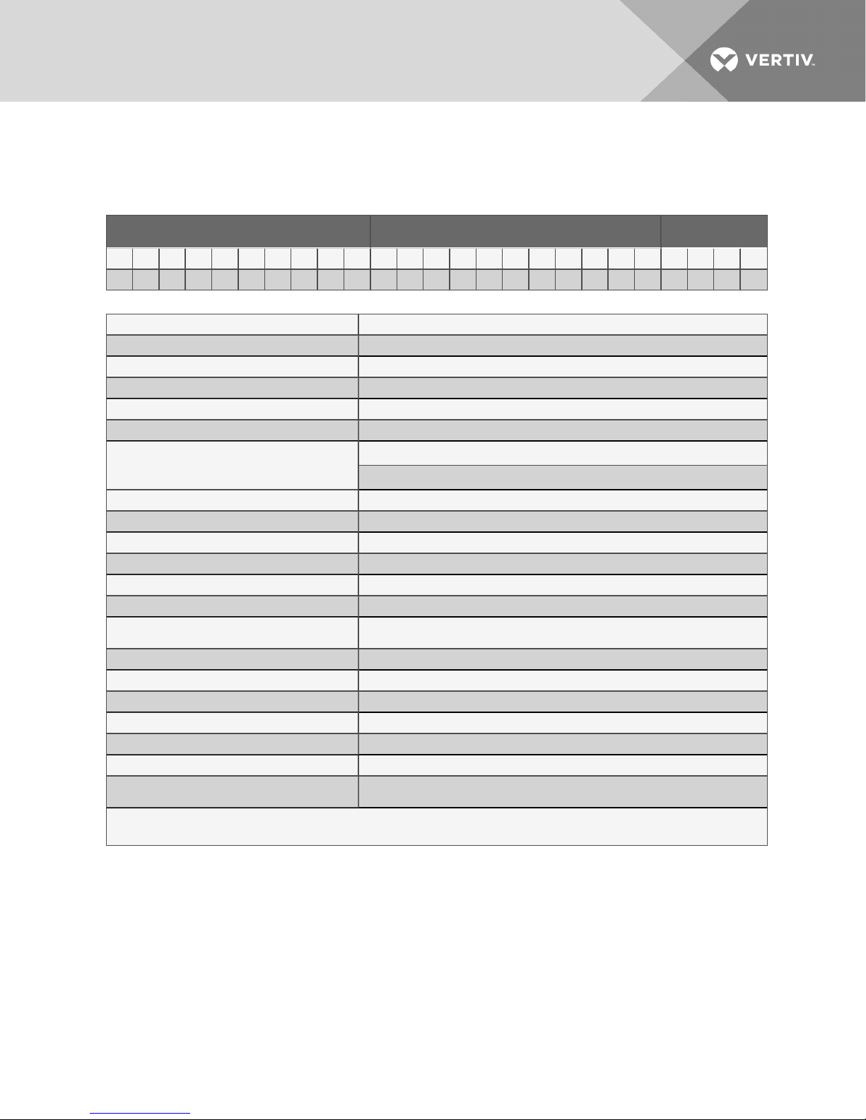
LIEBERT MC NOMENCLATURE
Model Number – Part 1/2 Model Details Part 2/2
1 2 3 4 5 6 7 8 9 10 11 12 13 14 1 5 16 17 18 19 20 21 22 23 24 25
M C M 0 4 0 E 1 A D 0 A 0 V U 0 0 0 0 0 0 * * * *
1-2. UnitFamily;MC = Liebert® MC™ 11. Coil Coating
3. PlatformSize 0 = None
S = S mall E = E-Coat (E poxy)
M = Medium 12. Panel Material
L = Large A = BrightAluminum
4-6. NominalCondenser Capacity, kW 13. Connection Pipe Unitof Measurement
028, 056, 040, 055, 080, 1 10, 160, 165, 220
Example: 040 = 40kW @ 95°F(35°C) &27°R
(15°K) ITD
7. Control/Fan Type V = 18" TallLegs (Std.)
E = Premium & EC Fan X = 36" Tall L egs with Bracing
8.RefrigerantCircuits/System Refrigeranttype Y = 48" Tall Legs with Bracing
1 = S ingle Refrigerant Circuit, R- 410A Z = 60" Tall Legs with Br acing
2 = Dual RefrigerantCircuit, R-410A 15. AgencyCertification
7 = Single RefrigerantCircuit, R-407C, R-22 U = CSA L isted, Marked with CSA c-us logo
8 = Dual Refrigerant Circuit, R- 407C, R-22
9.Power Supply 16.Undefined- Reservedfor Future Use
A = 4 60V / 3ph/60Hz 17. Liebert Lee-Temp™ Configuration
B = 575V / 3ph/60Hz 0 = No Receiver Leg/Software
Y = 208/230V/3ph/60Hz 1 = L iebert Lee-Temp Receiver L eg/Software
2 = 380V/3ph/60Hz 2 = Liebert DSE Receiver Leg/Software
10. Packaging 18-21. Undefined - Reserved For Future Use
D = D omestic, Non-Stackable (HorizontalAirflow
Orientation)
E = E xport Crating- Non-Stackable (HorizontalAirflow Orientation)
0 = Inches (Std. ACR Copper)
14. L egs Included
1 = IBC/OSHPD Seismic Certification, IBC/FBCWind Load Certification and
IBCSnowLoad Certification.
22-25. FactoryConfiguration Number
Vertiv | Liebert® MC™ Installer/User Guide | 9
Page 10

This page intentionally left blank.
Vertiv | Liebert® MC™ Installer/User Guide | 10
Page 11
1 INTRODUCTION
1.1 Product Description and Features
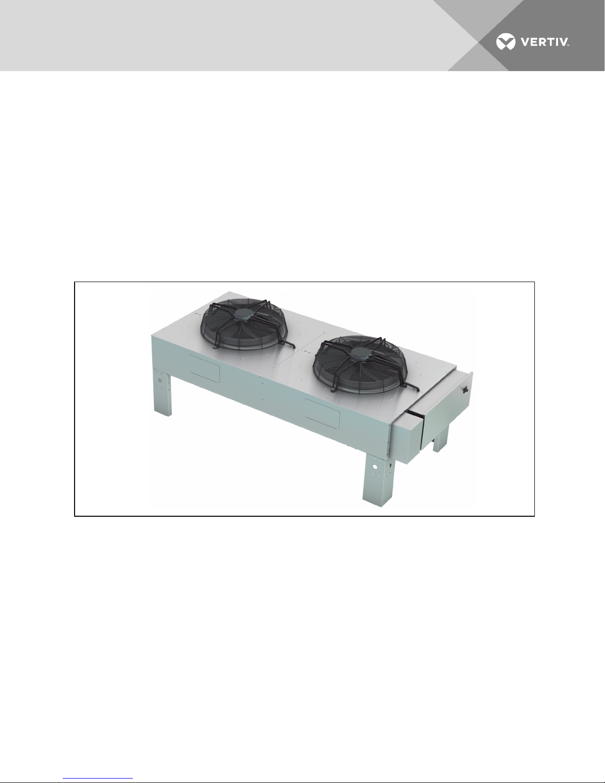
The Liebert MC condenser is a low-profile, direct-drive propeller fan-type air-cooled unit suitable for
mounting outdoors. It provides heat rejection for either one or two separate refrigeration circuits, matches
the heat rejection capacity corresponding with the outdoor ambient temperature and with each
corresponding compressor heat rejection requirements. Constructed with an aluminum cabinet,
galvanized steel frame and microchannel coil, the unit is quiet and corrosion resistant. The condenser is
quickly and easily installed, because all internal wiring is completed at the factory with only electrical
connections to be made at the job site. All electrical connections and controls are enclosed in an integral
weatherproof section of the condenser.
Figure 1.1 Two-fan Liebert MC
1.2 Control, Fan Types and Features
1.2.1 Premium Efficiency Control/EC Fan
Premium Efficiency Controls and EC fans are matched to provide superior system energy efficiency. The
premium control board allows CANbus communication with the indoor unit’s Liebert iCOM® control. This
communication feature provides compressor run signals, condenser operating mode changes, condenser
alarm monitoring, simplified system charging procedures and outdoor temperature monitoring. The fans
are controlled by the premium control board using pressure transducer signals from the refrigerant
circuit and factory programming to control the refrigerant head pressure.
Vertiv | Liebert® MC™ Installer/User Guide | 11
Page 12

The Premium Efficiency Control board on a Liebert MC with a dual refrigeration circuit adjusts the speed
of fans on each circuit to match each circuit’s head pressure conditions. On a Liebert MC with multiple
fans and a single refrigeration circuit, the premium control adjusts the fans to the same speed to maintain
head pressure. The control system provides refrigerant head pressure control for outdoor ambient
temperatures as low as -30°F (-35°C), provided that the total design range (from minimum to maximum) is
125°F (70°C) or less. For traditional DX applications, Liebert Lee-Temp™ kits are required only when the
design temperature ranges exceed 125°F (70°C) for standard match-ups and 115°F (65°C) for Liebert
Quiet-Line™ match-ups.
Anti-Freezing Operation
The EC fans must be operated periodically in cold weather to reduce the possibility of lockup due to ice
and snow accumulation. During periods of inactivity and outdoor temperatures below 35°F (1.6°C), the EC
fans will spin for at least 30 seconds every 15 minutes at 60% of the maximum fan speed.
Fan Reversal for Cleaning
The Liebert iCOM® can be used to run the Premium EC fans in reverse to clear loose debris from the coil
between scheduled coil cleanings. The fan reversal may be done manually or automatically based on a
user-programmed schedule. Automatic fan reversal interval occurs when the indoor unit is Off (BMS Off,
U2U network standby or Remote Shut Down [RSD]).
Low-Noise Feature
The low-noise feature allows setting the condenser fans to operate at a specified speed to reduce
operating noise at certain times. Special match-ups of premium condensers are available for applications
needing to meet stringent sound regulations. Lower sound levels are achieved by oversizing the
condenser, which decreases the maximum airflow and sound level produced by the condenser. This
feature requires special setup of the indoor unit. One or more Liebert Lee-Temp receivers are required.
The premium control has gain schedules that will override the user-defined low-noise schedule to prevent
a high-pressure condition from occurring.
1.3 Liebert Lee-Temp™Refrigerant Control
The Liebert Lee-Temp head pressure control system utilizes head pressure control valve(s), extra
refrigerant and insulated refrigerant receiver(s) with heater pads to assist system starting. The Liebert
Lee-Temp control system also maintains proper operating head pressures in outdoor temperatures below
the rating point of the Liebert MC control type. The system works by flooding the condenser coil with
liquid refrigerant to a level that balances the system condensing requirements with the condenser coil
surface available to reject the system heat. During the summer, the system requires the entire condenser
coil surface for heat rejection and most of the refrigerant is stored in the receiver. In the winter, the same
amount of heat can be rejected by only a fraction of the coil surface. As head pressure begins to fall, the
control valve restricts the flow of liquid refrigerant from the condenser. This extra liquid refrigerant
reduces the effective condenser surface area available for heat transfer. The head pressure control valve
also bypasses hot gas into the receiver to warm the liquid and maintain liquid pressure for proper
operation of the expansion valve. Liebert Lee-Temp kit is optional for condensers and is field-installed.
Condenser control boards are factory-configured for Liebert Lee-Temp if they are ordered with Liebert
Lee-Temp receivers. They can be field-configured if a Liebert Lee-Temp system is added later.
Vertiv | Liebert® MC™ Installer/User Guide | 12
Page 13

1.4 Surge Protective Device
An optional Surge Protective Device (SPD) can be field-wired to protect the condenser from power surges
that threaten sensitive equipment. The condenser’s electrical panel provides a terminal block to allow the
SPD to be wired in parallel with the high-voltage power. An additional low-voltage terminal block is
provided on condensers with Premium Control Boards to allow monitoring of the SPD alarm circuit.
ASCO 420™ Series surge protective device provides 50kA per mode of surge current protection. An
illuminated green LED indicates the SPD is On and operating properly. An illuminated red LED indicates
that the device may require replacement.
When both LEDs are Off, there is no power to the condenser, either from a power failure or because the
condenser disconnect is in the Off position.
Vertiv | Liebert® MC™ Installer/User Guide | 13
Page 14

This page intentionally left blank.
Vertiv | Liebert® MC™ Installer/User Guide | 14
Page 15
2 SITE PREPARATION
2.1 Site Considerations
• Condensers should be installed in a location offering maximum security and access for
maintenance.
• Avoid ground-level sites with public access and areas prone to heavy snow or ice
accumulations.
• To ensure adequate air supply, Vertiv™ recommends that condensers be installed in an area
with clean air, away from loose dirt and foreign matter that might clog the coil. In addition,
condensers should be located no closer than 3 feet (1m) from a wall, obstruction or adjacent
unit.
• For roof installation, mount the condenser on suitable curbs or other supports in accordance
with local codes.
• Condensers must not be installed in a pit.
• Condensers must be installed on a level surface to ensure proper refrigerant flow.
• Use caution when installing condensers below the indoor unit. Condensers must not be
installed more than 15ft. (4.6m) below the indoor unit. Condensers with Liebert Lee-Temp™
receivers must be installed at or above the level of the indoor units to maintain proper
subcooling.
• Liebert Lee-Temp receiver tanks should be mounted on the condenser legs for proper
operation. Contact Vertiv™ Application Engineering Department for assistance with
applications requiring remote mounting of receivers.
• Condensers must be installed in vertical airflow orientation to maintain the electrical box’s
NEMA 3R rating.
2.2 Dimensions and Weights
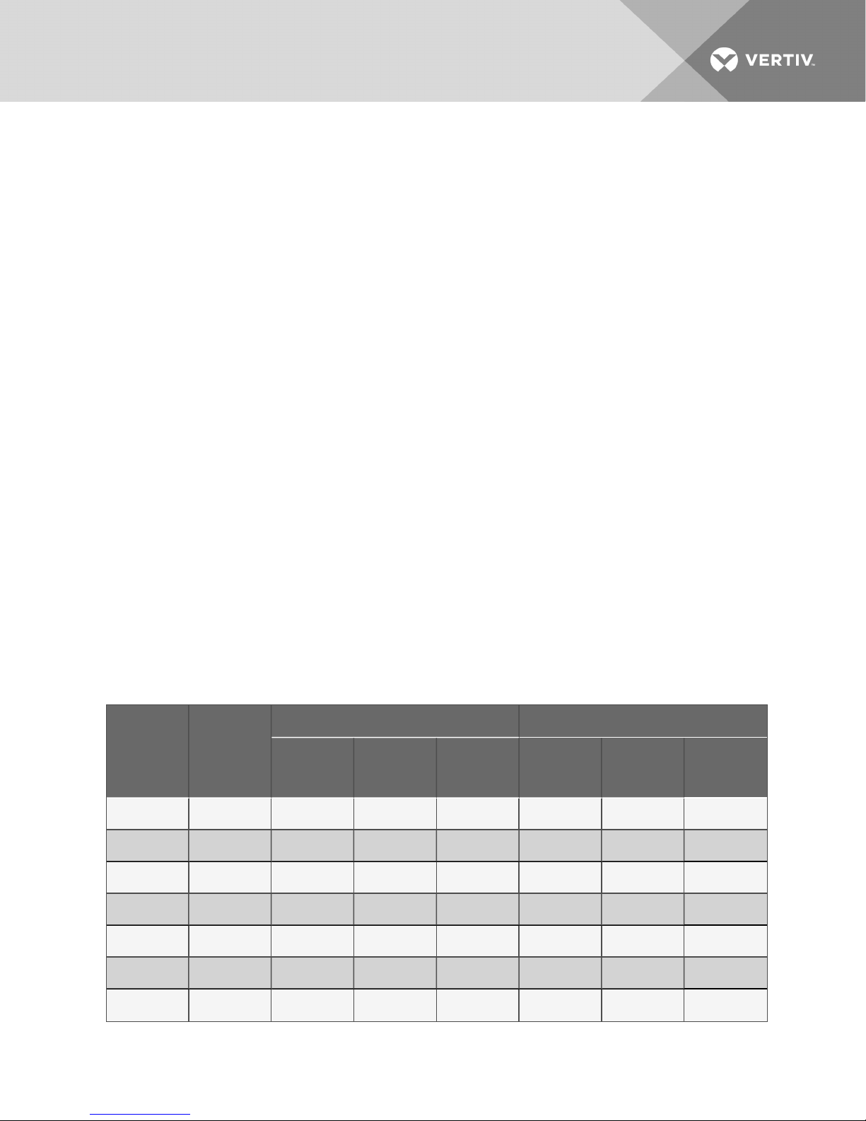
Table 2.1 Condenser shipping weights, dimensions and volume, approximate
Domestic Packaging Export Packaging
Model #
MCS028 1
MCS056 2
MCM040 1
MCM080 2
MCM160 4
MCL055 1
MCL110 2
Number of
Fans
Weight lb (kg)
359
(163)
562
(255)
439
(199)
769
(349)
1509
(684)
552
(250)
962
(436)
Dimensions
(L x W x H) in.
(cm)
76 x 36 x 63
(193 x 91 x 160)
122 x 36x 63
(310 x 91 x 160)
76 x 36 x 63
(193 x 91 x 160)
122 x 36x 63
(310 x 91 x 160)
256 x 36 x 63
(650 x 91 x 160)
76 x 36 x 63
(193 x 91 x 160)
136 x 36 x 63
(345 x 91 x 160)
Volume ft
3
(m3)
100 (2.8) 476 (216)
160 (4.5) 734 (333)
100 (2.8) 556 (252)
160 (4.5) 941 (427)
336 (9.5) 1834 (832)
100 (2.8) 669 (303)
179 (5.0) 1134 ( 514)
Weight lb (kg)
Dimensions
(L x W x H) in.
(cm)
77 x 37 x 64
(196x 94 x 163)
123 x 37 x 64
(312 x 94 x 163)
77 x 37 x 64
(196x 94 x 163)
123 x 37 x 64
(312 x 94 x 163)
257 x 37 x 64
(653 x 94 x 163)
77 x 37 x 64
(196x 94 x 163)
137 x 37 x 64
(348 x 94 x 163)
Volume ft
(m3)
106 (3.0)
161 (4.8)
106 (3.0)
161 (4.8)
352 ( 10)
106 (3.0)
188 ( 5.3)
3
Vertiv | Liebert® MC™ Installer/User Guide | 15
Page 16
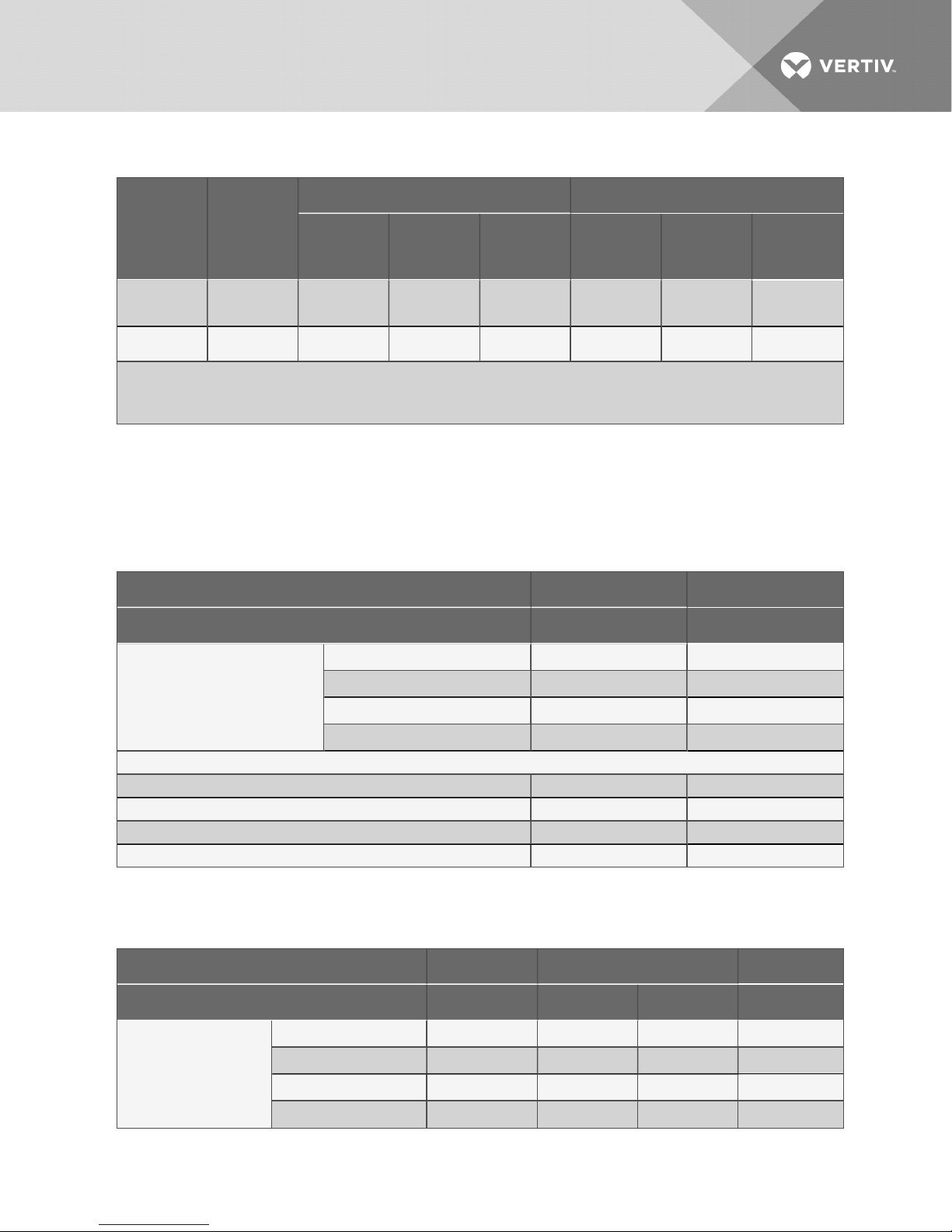
Table 2.1 Condenser shipping weights, dimensions and volume, approximate (continued)
Domestic Packaging Export Packaging
Model #
Number of
Fans
Weight lb (kg)
Dimensions
(L x W x H) in.
(cm)
Volume ft
(m3)
3
Weight lb (kg)
Dimensions
(L x W x H) in.
(cm)
Volume ft
(m3)
3
MCL165 3
MCL220 4
1. Packaged weights willincrease with factory options, such as legs taller than 1 8" (457mm) , coatedcoils, 575V andseismic/wind
options. See Table 2.2 below, Table 2.3 below and Table 2.4 on the facing page for option weights to add to the packaged weights
above. Consultfactory for additional information.
2. Receivers and60" legs are shipped separately from the condenser.
1364
(619)
1835
(832)
196 x 36 x 63
(498x 91 x 160)
256 x 36 x 63
(650 x 91 x 160)
257 (7.3) 1619 (734)
336 (9.5) 2160 (980)
197 x 37 x 64
(500 x 94 x
163)
257 x 37 x 64
(653 x 94 x 163)
270 (7.7)
352 ( 10)
2.2.1 Condenser and Options Net Weights
Total unit weight is the sum of the condenser weight with the selected legs plus the weight of any option.
Source: DPN003034, Rev. 1
Table 2.2 Condenser and option net weights—Small condensers
Condenser Model MCS028 MCS056
RefrigerationCircuits 1 2
154 (70) 270 (122)
286 (130) 419 (190)
318 (144 ) 451 (205)
349 (158) 482 (219)
Condenser Dry
Weight, lb (kg)
Additional Weight for Options, lb(kg)
18" Leg
36" L eg
48" Leg
60" Leg
Liebert L ee-Temp 55 ( 25) 110 (50)
Coated Coil 4 (2) 8 (4)
575V 52 (24) 63 (29)
Seismic/Wind Br acing, 18-in. legs 40 ( 18) 40 ( 18)
Table 2.3 Condenser and option net weights—Medium condensers
Condenser Model MCM040 MCM080 MCM16 0
RefrigerationCircuits 1 1 2 2
Condenser Dry
Weight, lb (kg)
Vertiv | Liebert® MC™ Installer/User Guide | 16
18" Leg
36" L eg
48" Leg
60" Leg
231 (105) 441 ( 200) 441 ( 200) 860 (390)
363 (165) 590 (268) 590 (268) 1066(484)
395 (1 79) 622 (282) 622 (282) 1114 (505)
426 (193) 653 (296) 653 (296) 1160 ( 526)
Page 17
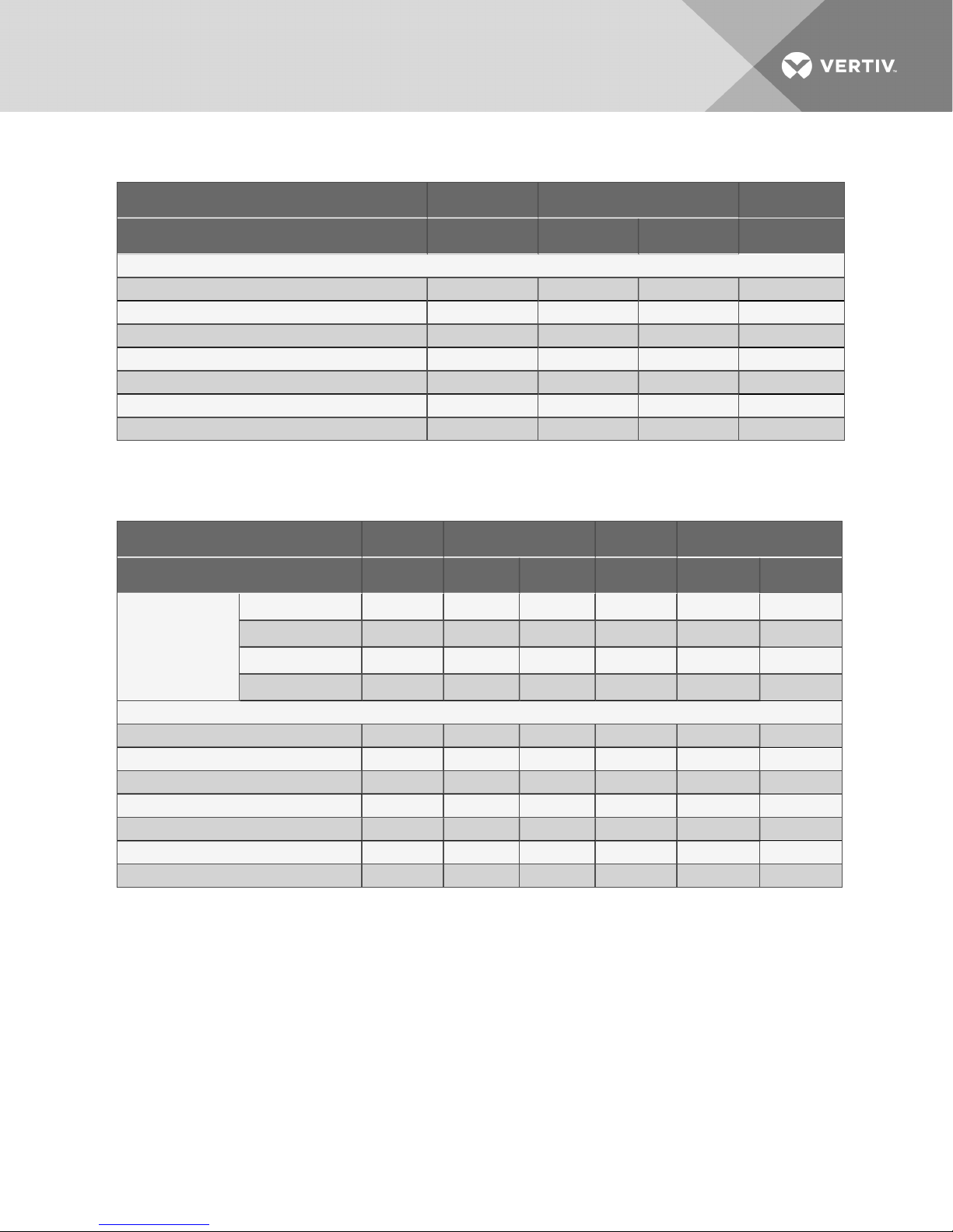
Table 2.3 Condenser and option net weights—Medium condensers (continued)
Condenser Model MCM040 MCM080 MCM16 0
RefrigerationCircuits 1 1 2 2
Additional Weight for Options, lb(kg)
Liebert L ee-Temp 55 ( 25) 100 (45) 110 (50) 220 (100)
Liebert DSE Receiver DA050 — 44 (20) — —
Liebert DSE Receiver DA080/085 — — — 88 (4 0)
Liebert DSE Receiver DA125/150/165 — — — 184 (83)
Coated Coil 5 ( 2) 10 (5) 10 (5) 20 (9)
575V 52 (24) 63 (29) 63 (29) 76 (34)
Seismic/Wind Br acing, 18-in. legs 4 0 (18) 40 (18) 40 (18) 57 (26)
Table 2.4 Condenser and option net weights—Large condensers
Condenser Model MCL055 MCL1 10 MC L165 MCL 220
RefrigerationCircuits 1 1 2 1 1 2
18" Leg
Condenser Dry
Weight, lb (kg)
Additional Weight for Options, lb(kg)
Liebert DSE Receiver DA050 — 45 (20) — 45 (20) — —
Liebert DSE Receiver DA080/085 — 45 (20) 90 (41) — 45 ( 20) 90 (41)
Liebert DSE Receiver DA125/150/165 — 94 (43) 188(85) 94 (43) 94 (43) 1 88 (85)
Seismic/Wind Br acing, 18-in. legs 40 (18) 40 ( 18) 40 (18) 57 ( 26) 57 (26) 57 (26)
36" L eg
48" Leg
60" Leg
Liebert L ee-Temp 60 (27) 115 (52) 120 (54) 175 (79) 215 (98) 240 (109)
344 (1 56) 602 (273) 602 (273) 891 ( 404 ) 1186 (538) 1186 (538)
486 (220) 766 (34 7) 766 (34 7) 11 36 (515) 1453 (659) 1453 (659)
518 (235) 798 (362) 798 (362) 1 184 (537) 1501 ( 681) 1501 (681)
549 ( 249) 829 ( 376) 829 (376) 1230 (558) 1547 (702) 1547 (702)
Coated Coil 8 (4) 16 (7) 16 (7) 24 (11) 32 (15) 32 (15)
575V 79 (36) 90 ( 41) 90 (41 ) 132 (60) 134 (61) 134 (61)
Vertiv | Liebert® MC™ Installer/User Guide | 17
Page 18
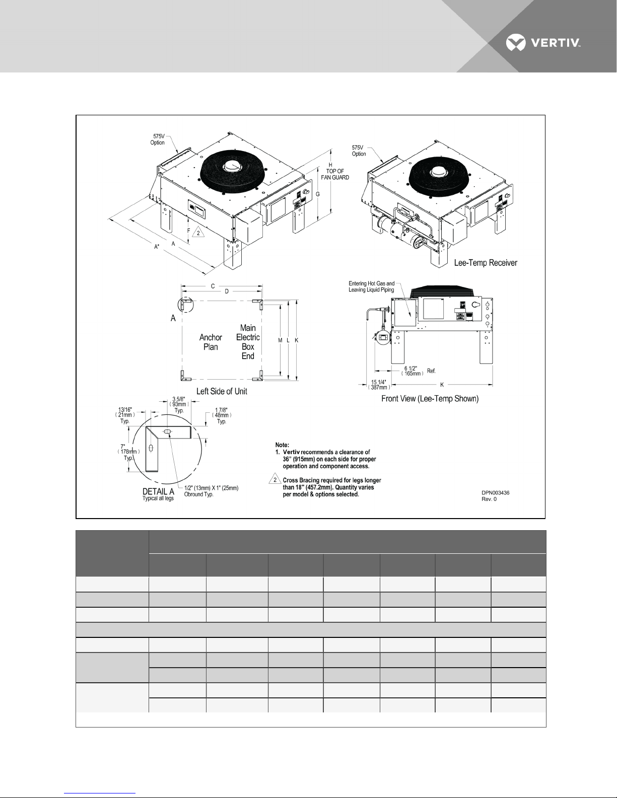
Figure 2.1 Condenser planning dimensional data—MCS028, MCM040 and MCL055
LiebertModel No.
A A* (575Vonly) C D K L M
MCS028 50-5/8 (1287) 58-7/8 (1495) 44-1 /8 (1120) 42-1 /2 (1080) 42- 1/2 ( 1080) 40- 7/8 (1038) 35-7/ 8 ( 910)
MCM040 57- 3/16 (1 453) 65-3/8 (1661) 48 (1219) 46-5/1 6 ( 1177) 46 (1168) 4 4-3/8 (1127) 39-5/16 (999)
MCL055 68 (1727) 77 (1956) 56 (1422) 54-3/8 (1381) 55-1/2 (1410) 53-78 (1368) 48-3/4 (1238)
Leg-heightDimensions in. (mm)
All Models F 1 8 ( 457) 36 (914 ) 4 8 (1219) 60 (1 524) -- --
MCS028
MCM040
MCL055
Source: DPN003436, Rev. 0
G 31-5/8 (803) 4 9-5/8 (1260) 61-5/8 (1565) 73-5/8 (1870) -- --
H 39-5/8 ( 1006) 57- 5/8 (1464) 69-5/8 (1768) 81- 5/8 (2073) -- --
G 35-7/8 (911) 53-7/8 (1368) 65-7/ 8 ( 1673) 77-7/8 (1978) -- --
H 43- 5/8 (1108) 61- 5/8 (1565) 73-5/8 (1870) 85-5/8 ( 2175) -- --
Vertiv | Liebert® MC™ Installer/User Guide | 18
Cabinet Dimensions in. (mm)
Page 19
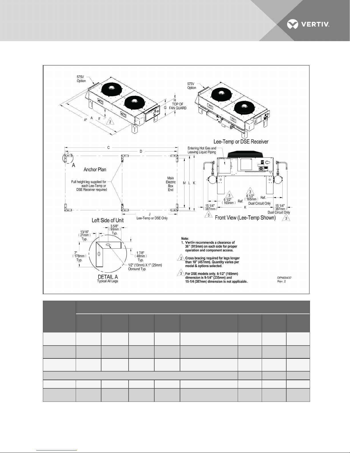
Figure 2.2 Condenser planning dimensional data—MCS056, MCM080, MCL110
LiebertModel
No.
MCS056
MCM080
MCL110
Leg-heightDimensions in. (mm)
All Models F 18 (457) 36 (914) 48 ( 1219) 60 (1524) -- - - --
MCS056
MCM080
A
94-7/8
(2411)
105-1/4
2674)
124- 1/8
(3152)
G 31 -5/8 (803)
A* (575V
only)
103-1/8
(2619)
113- 7/1 6
(2882)
133-1 /8
(3381)
Vertiv | Liebert® MC™ Installer/User Guide | 19
C D
88-3/8
(2245)
96-1/16
(2440)
112- 1/8
(2848)
49-5/8
(1260)
Cabinet Dimensions in. (mm)
J L ee-Temp or DSE
Receivers Only
86-3/4
(2203)
94-7/16
(2398)
110-1/ 2
(2806)
61-5/8
(1565)
42-1/2 (1079)
45-5/19 (1177) 46 (1168)
54-3/ 8 ( 1381)
73-5/8 (1870) -- -- --
K L M
42-1/2
(1080)
55-1/2
(1410)
40-7/8
(1038)
44- 3/8
(1127)
53-7/8
(1368)
35-7/8
(910)
39-5/16
(999)
48-34
(1238)
Page 20
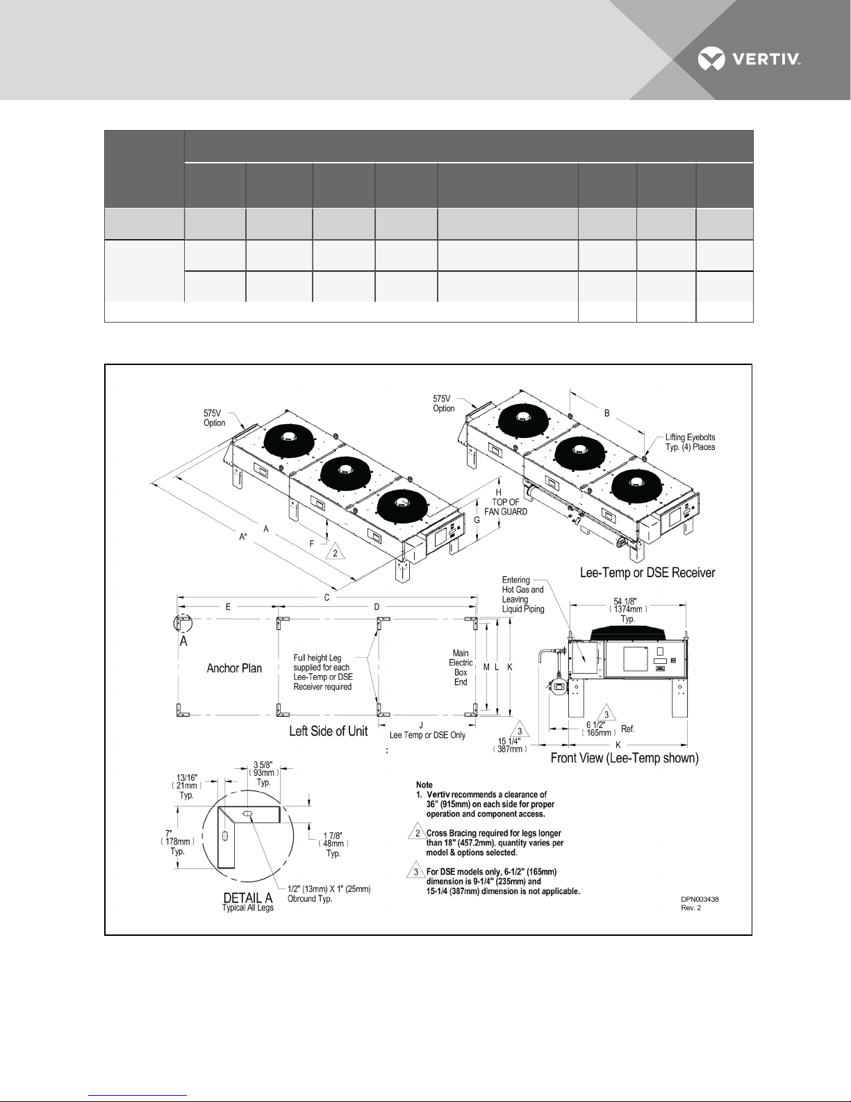
LiebertModel
No.
Cabinet Dimensions in. (mm)
A
A* (575V
only)
C D
J L ee-Temp or DSE
Receivers Only
K L M
H
G 35-7/8 (911)
MCL110
H
Source: DPN003437, Rev. 2
39-5/8
(1006)
43-5/8
(1108)
57-5/8
(1464)
53-7/8
(1368)
61-5/8
(1565)
69-5/8
(1768)
65-7/8
(1673)
73-5/8
(1870)
Figure 2.3 Condenser planning dimensional data—MCL165
81-5/8 (2073) -- -- --
77-7/8 (1978) -- -- --
85-5/8 (2175) - - -- --
Vertiv | Liebert® MC™ Installer/User Guide | 20
Page 21

LiebertModel
No.
Dimensions in. (mm)
A
A*
(57Vonly)
B C D E
J
Lee-Temp or DSE
Receivers Only
K L M
MCL165
Leg-height Dimensions in. (mm)
MCL165
Source: DPN003438, Rev. 2
180-1/4
(4578)
F 18 (457) 36 (914) 48 (1219) 60 (1524) - -
G 35-7/ 8 ( 911) 53-7/8 (1368) 65-7/8 (1673) 77-7/8 (1978) --
H 43-5/8 ( 1108) 61-5/8 (1565) 73- 5/8 (1870) 85-5/8 (2175) --
189-1/4
(4807)
73-7/ 16
(1866)
168-1/4
(4274)
110-1/ 2
(2806)
56-1/8
(1425)
54-3/ 8 ( 1381)
Figure 2.4 Condenser planning dimensional data—MCM160 and MCL220
55-1/2
(1410)
53-7/8
(1368)
48-3/4
(1238)
Vertiv | Liebert® MC™ Installer/User Guide | 21
Page 22
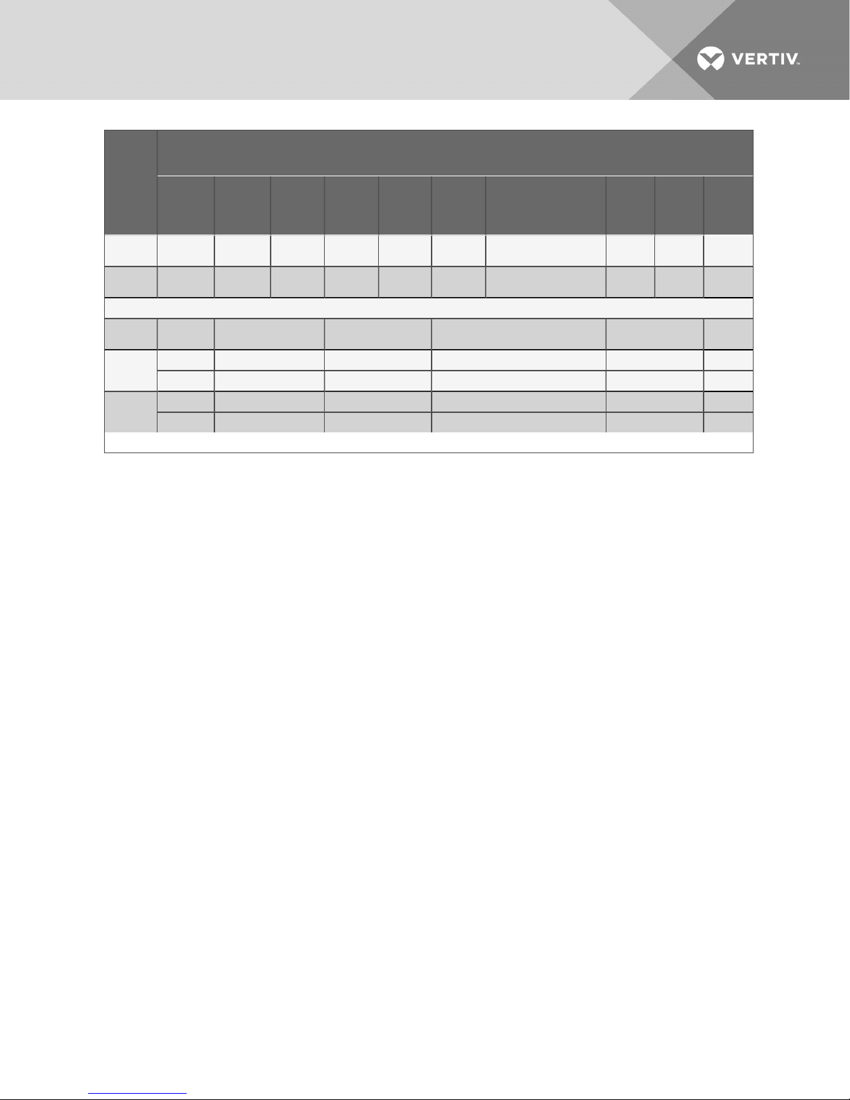
Liebert
Model
No.
Cabinet Dimensions
in.(mm)
A
A*
(575V
only)
B C D E
J L ee-Temp or DSE
Receivers Only
K L M
MCM160
MCL220
Leg-heightDimensions in. (mm)
All
Models
MCM160
MCL220
Source: DPN003439, Rev. 2
202-7/ 16
(514 2)
236-5/16
(6003)
F 18 ( 457) 36 (914) 48 (1219) 60 (1524) - -
G 31-5/8 ( 803) 49-5/8 (1260) 61-5/8 (1565) 73-5/8 (1870) - -
H 39-5/8 (1006) 57-5/8 ( 1464) 69-5/8 (1768) 81-5/8 (2073) --
G 35-7/8 (911) 53-7/8 (1368) 65-7/8 (1673) 77-7/8 (1978) - -
H 4 3-5/8 (1108) 61-5/8 ( 1565) 73-5/8 (1870) 85-5/8 ( 2175) --
210-5/8
(5350)
245-5/16
(6231)
113- 1/2
(2883)
129-9/16
(3291)
192-1/ 4
(4883)
224-3/8
(5699)
94-7/16
(2398)
110-1/ 2
(2806)
96-3/16
(2444)
112- 1/4
(2851)
45-5/16 (1177)
54-3/ 8 ( 1381)
46
(1168)
55-1/2
(1410)
44- 3/8
(1127)
53-7/8
(1368)
39-5/16
(999)
48-3/4
(1238)
Vertiv | Liebert® MC™ Installer/User Guide | 22
Page 23

Figure 2.5 Liebert DSE receiver mounting—MCL165 and MCL220, single-circuit condenser,
left-sidecondenser outlet receiver
Vertiv | Liebert® MC™ Installer/User Guide | 23
Page 24
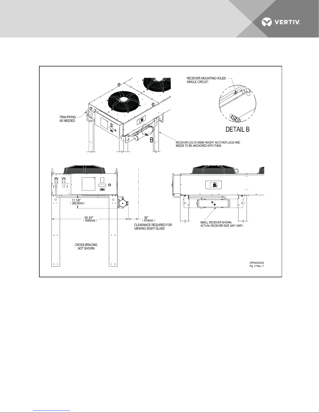
Figure 2.6 Liebert DSE receiver mounting—MCL165 and MCL220, single-circuit condenser,
right-sidecondenser outlet receiver
Vertiv | Liebert® MC™ Installer/User Guide | 24
Page 25
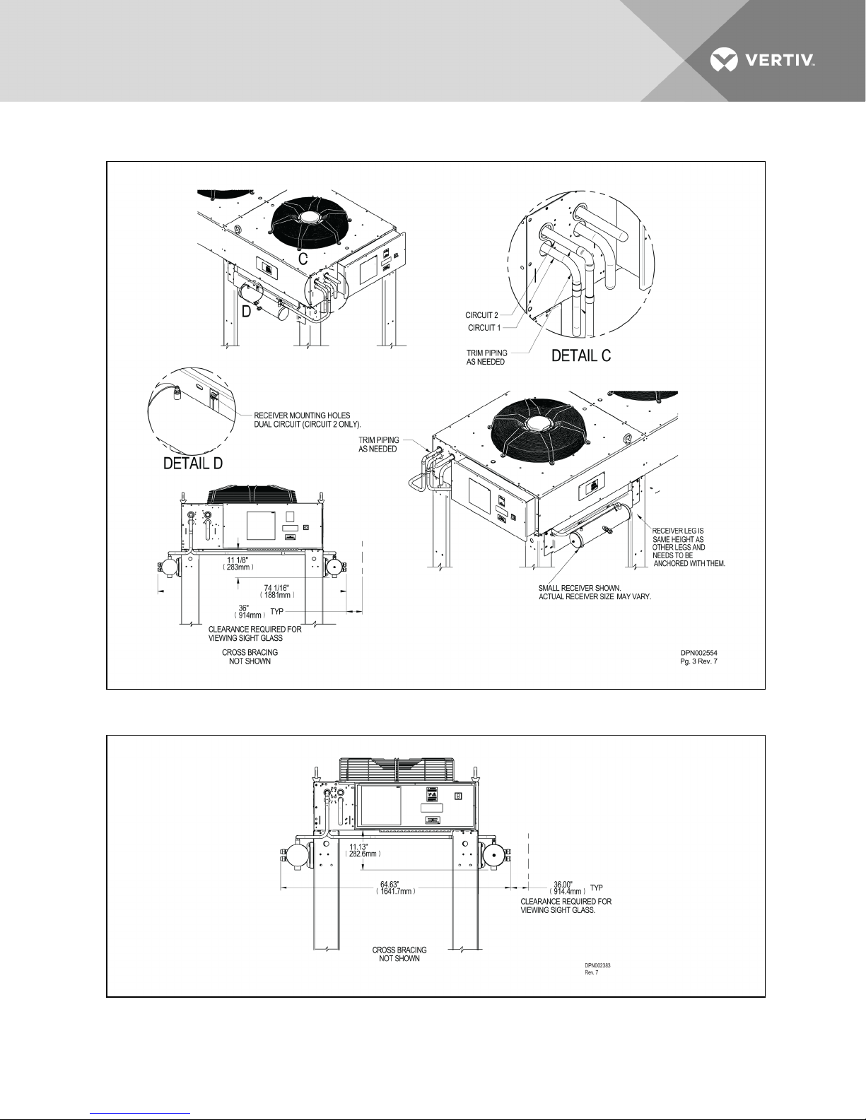
Figure 2.7 Liebert DSE receiver mounting—MCL110 and MCL220, dual-circuit condenser
Figure 2.8 Liebert DSE receiver mounting—MCM160 dual circuit condenser
Vertiv | Liebert® MC™ Installer/User Guide | 25
Page 26

This page intentionally left blank.
Vertiv | Liebert® MC™ Installer/User Guide | 26
Page 27
3 INSPECTION AND INSTALLATION
Safety Information
WARNING! Risk of improper handling. Can cause equipment damage, injury or death.
Read all of the following instructions before attempting to move, lift, remove packaging from or
preparing unit for installation.
WARNING! Risk of heavy condenser falling or tipping over. Can cause property damage,
serious injury or death.
Confirm that all components of the lifting system are rated for the weight of the condenser by
an OSHA Certified rating organization before attempting to lift and/or move the condenser. See
2.2 on page15 throughCondenser and option net weights—Large condensers on page17 for
the condenser weights.
CAUTION: Risk of contact with sharp edges, splinters and exposed fasteners. Can cause
personal injury.
Only properly trained and qualified personnel wearing appropriate safety headgear, gloves,
shoes and glasses should attempt to move, lift, remove packaging from or prepare unit for
installation.
NOTICE
Risk of interference with building doorways, openings and passages. Can cause unit and/or building
damage.
Refer to the installation plans and measure the unit and building opening before moving the unit to verify
clearances.
NOTICE
Risk of improper forklift handling. Can cause unit damage.
Keep the forklift tines level and at a height that will fit under the skid.
NOTICE
Risk of improper storage. Can cause unit damage.
Keep unit upright and protected from contact damage.
Vertiv | Liebert® MC™ Installer/User Guide | 27
Page 28
3.1 Equipment Inspection
Upon arrival of the unit and before unpacking, verify that the labeled equipment matches the Bill of
Lading. Carefully inspect all items for either visible or concealed damage. Damage should be immediately
reported to the carrier and a damage claim filed with a copy sent to Vertiv™ or to your sales
representative.
If you have the seismic mounting kit, refer to Liebert Seismic Application—OptionalUnitConfiguration on
page99
3.1.1 Packing Material
All material used to package this unit is recyclable. Please save it for future use or dispose
of the material appropriately.
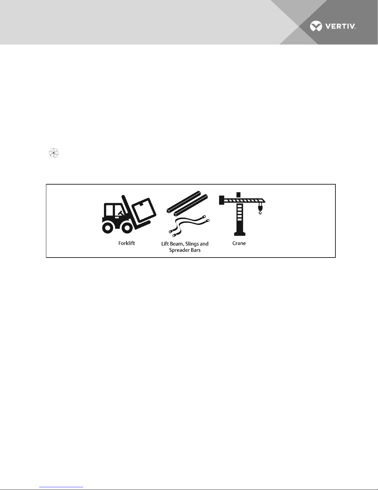
Figure 3.1 Equipment recommended for handling a Liebert condenser
3.2 Handling Unit on the Skid
Transport unit using a fork lift or a crane with sling and spreader bars.
Using a forklift
NOTICE
Risk of improper forklift handling. Can cause unit damage.
Keep the forklift tines level and at a height that will fit under the skid.
• Make sure the forks (if adjustable) are spread to the widest allowable distance to still fit under
the skid.
• Type of forklift used will depend on the terrain the unit is to be moved across during handling.
• Minimum forklift fork length:
• for 1-fan and 2-fan units—48” (1219mm)
• for 3-fan and 4-fan units—72” (1829mm)
• When moving the packaged unit, do not lift it any higher than 6" (152mm). If the unit must be
lifted higher than 6" (152mm), great care must be exercised and no one may be closer than 20'
(6m) to the lift point.
• Vertiv™ recommends lifting one end off the ground no more than 6" (152mm)and using the
forklift to push or pull the unit.
Vertiv | Liebert® MC™ Installer/User Guide | 28
Page 29
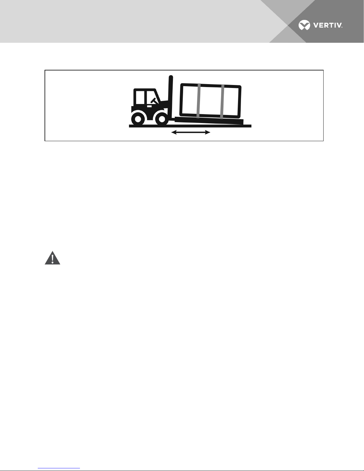
Figure 3.2 Forklift position with 1- to 4-fan condensers
Using a Crane
• Vertiv™ recommends using slings rated for the unit weight.
• Spreader bars must be used for sling stability and to keep the slings from pressing against the
unit. Make sure spreader bars are wider than the unit.
• Place the slings near the ends of the unit, under the top deck boards of the skid.
3.3 Unit Storage
Store the condenser in the original packaging in an area protected from excessive dirt, debris and
contact damage until final installation.
3.4 Unpacking the Condenser—All Unit Sizes
CAUTION: Risk of contact with sharp edges, splinters and exposed fasteners. Can cause
personal injury.
Only properly trained and qualified personnel wearing appropriate safety headgear, gloves,
shoes and glasses should attempt to move, lift, remove packaging from or prepare unit for
installation.
Refer to Figure 3.3 on the next page for the following steps:
1. Remove the fence for domestic packaging (for export packaging, remove the crate).
2. Remove the exterior foam from around the unit and the electric box.
3. Remove the steel straps securing the unit to the skid.
4. Set the legs aside, but keep accessible if legs are shipped together with the unit.
• Depending on the number of fans, more or less steel straps may be removed at this step.
5. Remove corrugated panels covering the condenser’s coil(s).
6. Remove the bolts securing unit to the skid.
7. Remove the bolts securing the brackets to the unit and recycle the brackets.
Vertiv | Liebert® MC™ Installer/User Guide | 29
Page 30

Figure 3.3 Removing protective material
3.5 Preparing a Condenser for Moving and Installation
The following procedure is one method for removing a Liebert condenser from its shipping skid. Other
methods may be used, provided that they are safe for personnel, the condenser and other equipment.
3.5.1 Attaching 18" (457mm) Legs, RemovingtheSkidandAttachingSlings
NOTE: Units supplied with 36-60” (914-1524mm) legs go to Attaching36to60in.
(914to1524mm)Legs, RemovingtheSkidandAttaching Slings on page33.
1. Attach legs to the unit at indicated locations, using the fasteners provided with the legs.
• Recommended tools for attachment is a 1/2” (13mm) socket and ratchet.
• More legs may be available for installation than are shown. This will depend on the unit
type and number of fans.
Vertiv | Liebert® MC™ Installer/User Guide | 30
Page 31
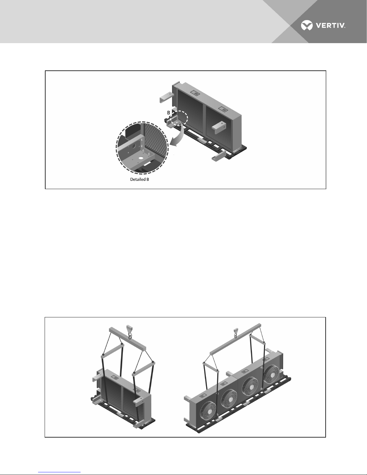
Figure 3.4 Attaching legs to condensers
2. Place slings around the unit between the unit and the top deck boards of the skid as shown in
Figure 3.5 below:
• 1-fan and 2-fan units: against the inside of the attached legs.
• 3-fan and 4-fan units: against the outside of the attached eye bolts.
3. Use spreader bars, a lift beam and a crane to lift the unit off the skid. Make sure spreader bars
are wider than the unit.
NOTICE
Risk of improper lifting. Can cause equipment damage.
Make sure that the spreader bars wider are than the unit. If the spreader bars are too short, the slings may
crush the unit.
Figure 3.5 Securing slings to condensers for lifting off skid
Vertiv | Liebert® MC™ Installer/User Guide | 31
Page 32
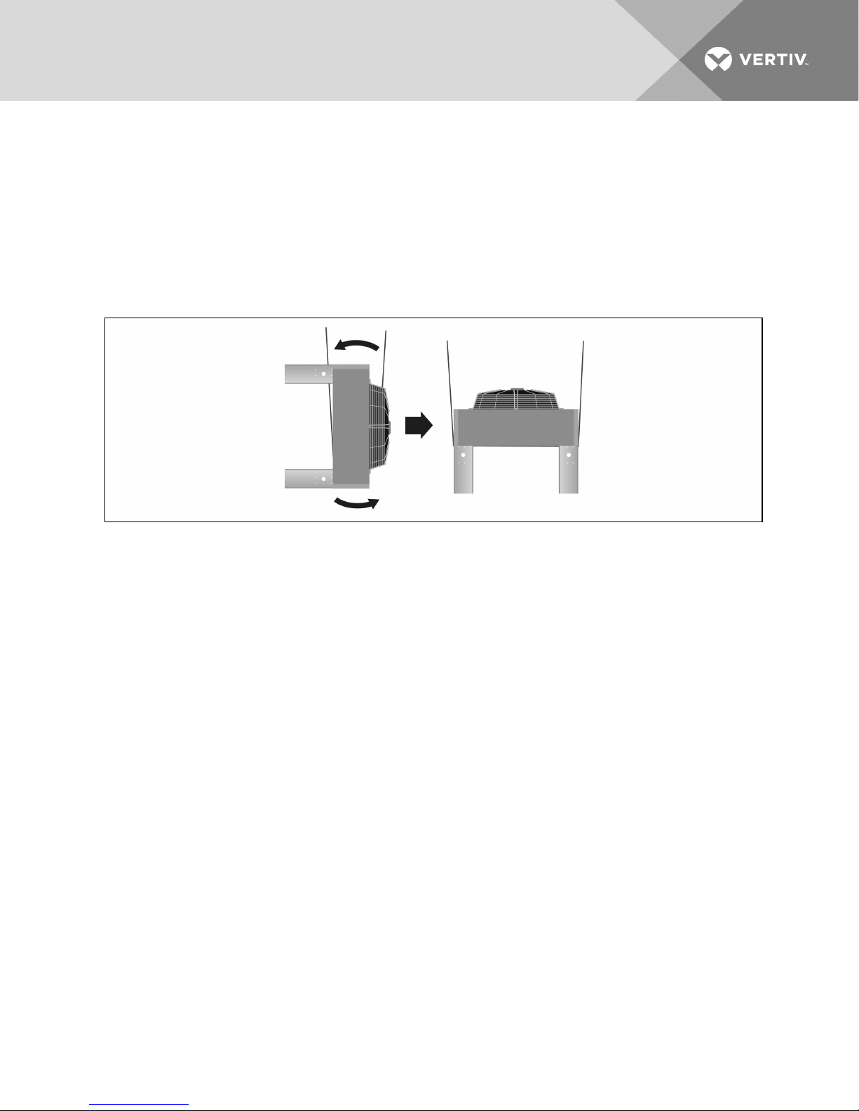
4. Lift the unit 24" (610mm) off the top deck of the skid.
5. Remove the skid from under the unit.
6. To rotate the unit, a mechanized method is recommended, but if one is not available, use a
minimum of four properly-protected individuals to rotate the elevated unit 90 degrees so the
unit legs are pointing toward the ground, Figure 3.6 below.
7. Set the upright unit on the ground so the legs support unit weight.
8. Remove the straps from around unit.
Figure 3.6 Rotate and set condenser on floor
9. Refer to Figure 3.7 on the facing page to attach rigging for lifting.
Spreader bars are still required. Make sure that the spreader bars are wider than the unit to
prevent crushing force.
• 1-fan and 2-fan units: Route the straps through the large holes in the side of the legs.
• 3-fan and 4-fan units: Secure straps or chains to the eye bolts on top of the unit.
NOTICE
Risk of improper lifting. Can cause equipment damage.
Make sure that the spreader bars wider are than the unit. If the spreader bars are too short, the slings may
crush the unit.
The unit is ready to be lifted and moved to its installation location.
Vertiv | Liebert® MC™ Installer/User Guide | 32
Page 33
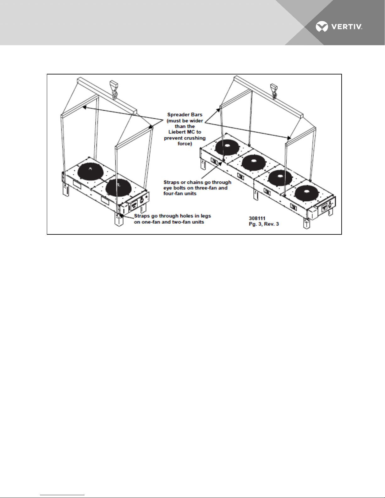
Figure 3.7 Rigging to lift condensers
3.5.2 Attaching36to60in.(914to1524mm)Legs, RemovingtheSkidandAttaching
Slings
1. Install bolts for sling-containment guides during lifting/rotation:
• Locate the recommended bolt locations shown in Figure 3.8 on the next page.
• Insert 4 leg bolts, 2 on each end, leaving approximately 1/4in. (6mm) of the fastener
threads exposed.
• Do not inser bolt in the secondary bolt locations. These are used to attached the legs
after the unit is moved into the installation location.
2. Assemble the leg structure according to the instructions supplied with the legs. Cross-bracing
for 4legs is shown in Figure 3.8 on the next page.
NOTE: When assembling the leg structure, DO NOT tighten the cross-brace hardware until the
condenser cabinet is fastened to the legs.
Vertiv | Liebert® MC™ Installer/User Guide | 33
Page 34
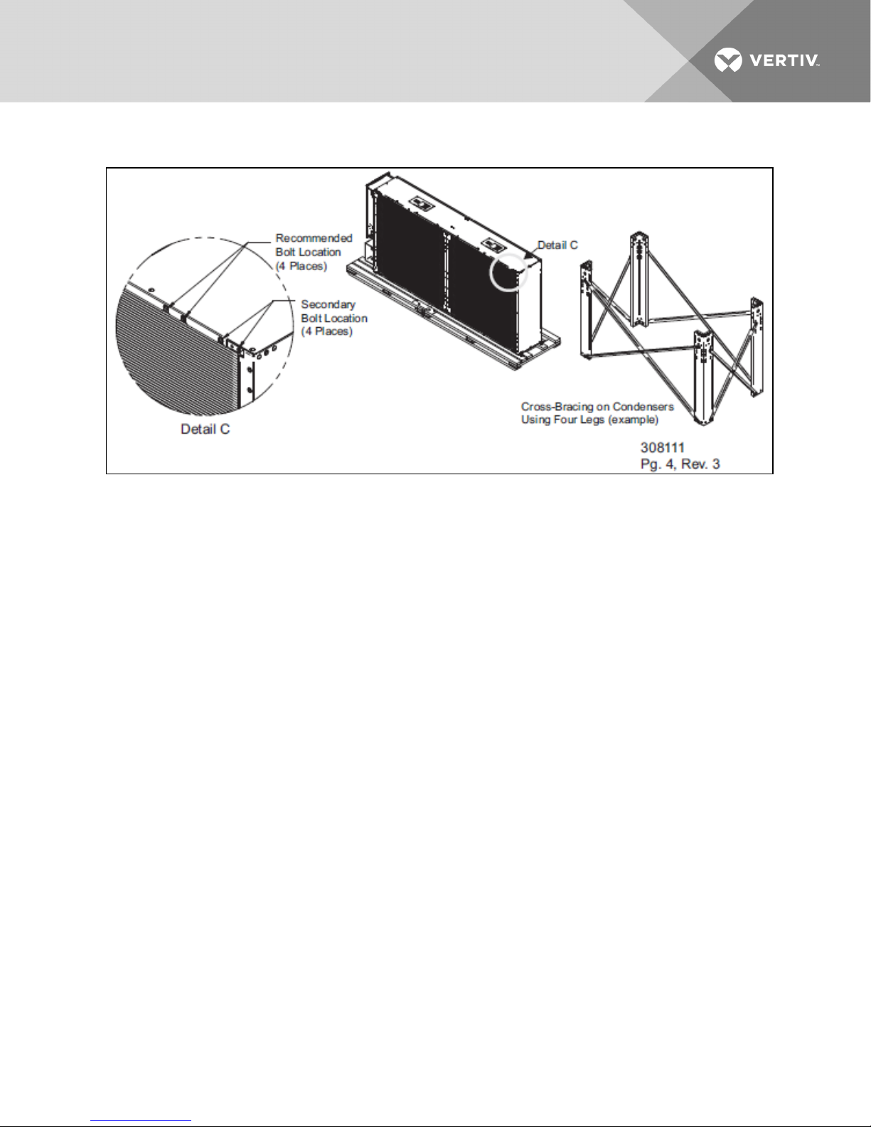
Figure 3.8 Recommended bolt locations for lifting, example cross-bracing for 4 legs
3. To attach rigging for lifting, attach slings between the unit and the top deck boards of the skid
asfollows:
Spreader bars are required. Make sure that the spreader bars are wider than the unit to
prevent crushing force.
• 1-fan and 2-fan units: Route the slings against the inside of the inserted leg bolts
asshowninFigure 3.9 on the facing page.
• 3-fan and 4-fan units: Route the slings against the outside of the attached eye bolts.
NOTICE
Risk of improper lifting. Can cause equipment damage.
Make sure that the spreader bars wider are than the unit. If the spreader bars are too short, the slings may
crush the unit.
4. Use spreader bars, lift beam and crane to lift the the unit 24in. (610mm) off the skid. Remove
the skid from under the unit
5. To rotate the unit, a mechanized method is recommended, but if one is not available, use a
minimum of four properly-protected individuals to rotate the elevated unit 90 degrees so the
unit fans are facing up, Figure 3.9 on the facing page.
Vertiv | Liebert® MC™ Installer/User Guide | 34
Page 35
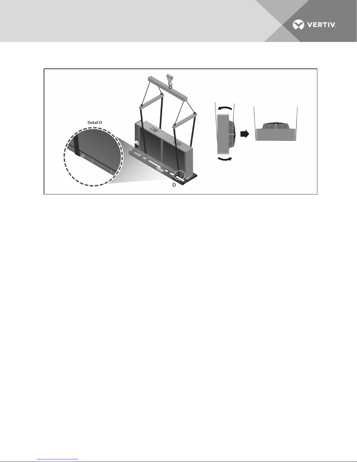
Figure 3.9 Sling placements and unit rotation
6. Place the unit on the leg structure, resting the unit on the legs.
7. Remove the bolts inserted for strap containment. If the secondary locations were used, remove
the bolts just before setting the unit on its legs.
8. Align, insert and tighten all hardware securing the unit to the leg structure.
9. Square-up the leg structure and tighten all cross-brace angle hardware.
10. Lower the unit so the leg structure supports the weight of the unit, and remove the straps from
around the unit.
11. Refer to Figure 3.10 on the next page to attach rigging for lifting.
Spreader bars are still required. Make sure that the spreader bars are wider than the unit to
prevent crushing force.
• 1-fan and 2-fan units: Route the straps through the large holes in the side of the legs.
• 3-fan and 4-fan units: Secure straps or chains to the eye bolts on top of the unit.
NOTICE
Risk of improper lifting. Can cause equipment damage.
Make sure that the spreader bars wider are than the unit. If the spreader bars are too short, the slings may
crush the unit.
The unit is ready to be lifted and moved to its installation location.
Vertiv | Liebert® MC™ Installer/User Guide | 35
Page 36
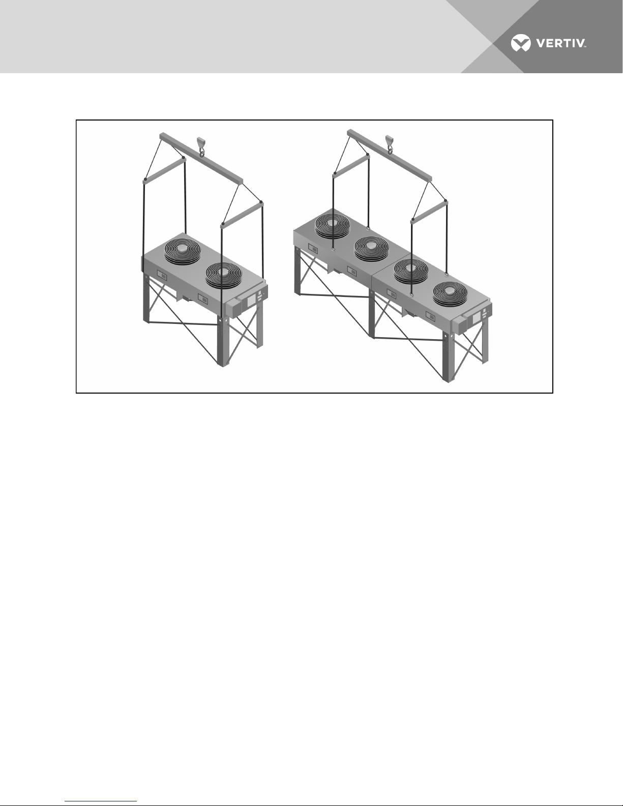
Figure 3.10 Rigging to lift the unit for installation
3.6 Mounting the Condenser
The condenser must be installed so that it is level within 1/2” (13mm) to ensure proper refrigerant flow. For
roof installation, mount the condenser on suitable curbs or other supports. Follow all local and national
codes.
3.6.1 Standard Mounting Requirements
Secure the legs to the mounting surface using field-supplied 3/8” (9.5mm) diameter Grade 5 bolts with a
flat washer in each of the two 1/2” x 1" (12.7 x 25.4mm) obround holes in each leg. See Figure 2.1 on page18
through Figure 2.4 on page21 for anchor dimensions.
3.6.2 Seismic-Certified and Wind-Certified Mounting Requirements
Mounting requirement details such as anchor brand, type, embedment depth, edge spacing,
anchor-to-anchor spacing, concrete strength, special inspection and attachment to non-building
structures must be outlined and approved by the engineer of record for the project or building.
Structural floors and housekeeping pads must also be designed and approved by the project or building
structural engineer of record to withstand the seismic or wind anchor loads as defined on the installation
drawings. The installing contractor is responsible for the proper installation of all anchors and mounting
hardware, observing the mounting requirements detailed in the seismic or wind installation drawings and
additionally outlined by the engineer of record.
Vertiv | Liebert® MC™ Installer/User Guide | 36
Page 37

At a minimum, 3/8” Grade 5 anchors with American National Standard Series W, Type A, plain washers
(ANSI B18.22.1-1965, R1975) selected to match the nominal anchor diameter must be installed at each
anchor location between the anchor head and equipment for tension load distribution. See Liebert
Seismic Application—OptionalUnitConfiguration on page99 for additional information.
Vertiv | Liebert® MC™ Installer/User Guide | 37
Page 38

This page intentionally left blank.
Vertiv | Liebert® MC™ Installer/User Guide | 38
Page 39
4 ELECTRICAL CONNECTIONS
Line voltage electrical service is required for all models. Refer to the equipment’s nameplate regarding
wire size and circuit protection requirements. Electrical service must conform to national and local
electrical codes. Refer to Figure 4.8 on page50 for electrical service entrances into unit. Refer to
electrical schematic when making connections.
A manual electrical disconnect switch should be installed in accordance with local codes. Consult local
codes for external disconnect requirements.
All internal wiring is completed at the factory.
WARNING! Risk of electrical shock. Can cause injury or death.
The fan speed control and the EC fan electrical enclosures may contain a stored electrical
charge. Open all local and remote electric power disconnect switches, wait 10 minutes and verify
with a voltmeter that power is Off before working within the fan speed control and the EC fan
electrical enclosures.
The LiebertMC contains lethal voltage in some circuits. The line side of the disconnect remains
energized when the condenser unit disconnect is switched to the Off position.
Use a voltmeter to verify that the line-side electrical power is Off before making any electrical
connections or performing any electrical and/or mechanical service and/or maintenance
operations.
WARNING! Risk of contact with high-speed, rotating fan blades. Can cause serious injury or
death.
Fan blades can automatically start rotating without warning at any time during a cooling cycle
or after power is restored after a power failure. Open all local and remote electric power supply
disconnect switches and verify with a voltmeter that the power is Off and that the fan blades
have stopped rotating before working within the cabinet or servicing fan motors.
Each unit is shipped from the factory with all internal wiring completed. Refer to the electrical
schematic supplied with the condenser when making line voltage supply, low-voltage indoor
unit interlock and any low-voltage alarm connections. All wiring must be done in accordance
with all applicable local, state and national electrical codes.
NOTE: Installation and service of this equipment should be done only by properly trained and qualified
personnel who have been specially trained in the installation of air conditioning equipment.
NOTE: Use copper wiring only. Make sure that all connections are tightened to the proper torque
mentioned on the component.
Vertiv | Liebert® MC™ Installer/User Guide | 39
Page 40
4.1 Line Voltage Wiring
WARNING! Risk of electrical fire and short circuit. Can cause property damage, injury or death.
Select and install the line side electrical supply wire and overcurrent protection device(s)
according to the specifications on the unit nameplate(s), per the instructions in this manual
and according to the applicable national, state and local code requirements. Use copper
conductors only.
Verify that all electrical connections are tight. Unit-specific wiring diagrams are provided on
each unit.
NOTE: The LiebertMC Condenser is designed to operate with Wye-connected power with a solidly
grounded neutral. It will not operate properly with Wye-connected power with high-resistance (or
impedance) ground or with delta-connected power. Refer to Wye- vs. Delta-Connected Power Supply
on page42.
Condenser-rated voltage should be verified with available power supply before installation. Refer to the
unit’s electrical schematic and serial tag for specific electrical requirements.
Liebert MC condenser power connections are provided for three-phase wires and 1 earth ground wire.
Line voltage electrical service is required for all condensers at the location of the condenser. The voltage
supply to the condenser may not be the same voltage supply as required by the indoor unit. Consider
using a UPS on both data center cooling units and Liebert MC condensers to maintain uninterrupted
cooling capability. Refer to the unit’s serial tag for specific condenser electrical requirements. A unit
disconnect is standard. However, a site disconnect may be required by local code to isolate the unit for
maintenance. Route the supply power to the site disconnect switch and then to the unit. Route the
conduit to the knockout provided in the bottom right end of the electrical control enclosure. Connect the
earth ground wire lead to the marked earth ground connection terminal provided near the factoryinstalled disconnect switch (see Figure 4.8 on page50).
NOTE: Liebert Lee-Temp™ kits require a separate line voltage electrical supply for the heated receivers.
See Table 4.2 on the facing page for power requirements.
Table 4.1 Electrical data, three-phase, 60Hz condenser, premium models
Model Voltage FLA WSA OPD
Small Platform
208/230V 3.0 3.8 15
MCS028
MCS056
Medium Platform
Vertiv | Liebert® MC™ Installer/User Guide | 40
380V 1.4 1.8 15
460V 1.4 1.8 15
575V 1.2 1.5 15
208/230V 6.0 6.8 15
380V 2.8 3.3 15
460V 2.8 3.3 15
575V 2.3 2.8 15
Page 41
Table 4.1 Electrical data, three-phase, 60Hz condenser, premium models (continued)
Model Voltage FLA WSA OPD
208/230V 2.3 3.2 15
MCM040
MCM080
MCM160
Large Platform
MCL055
MCL110
MCL165
MCL220
1. FLA = Full Load Amps; WSA = Wire Size Amps; OPD = Maximum Over current ProtectionDevice.
2. 208V–575V premium models must be connectedto Wye three-phase s ystems.
3. Wye 3-phase s ystems with solidly grounded neutral. Refer to Wye- vs. Delta-ConnectedPower Supply on the next page.
380V 1.4 1.9 15
460V 1.4 1.9 15
575V 1.2 1 .6 15
208/230V 4.6 5.5 15
380V 2.8 3.3 15
460V 2.8 3.3 15
575V 2.3 2.8 15
208/230V 9.2 9.8 15
380V 5.6 6.0 15
460V 5.6 6.0 15
575V 4.7 5.0 15
208/230V 5.7 7.1 15
380V 2.8 3.5 15
460V 2.8 3.5 15
575V 2.3 2.9 15
208/230V 1 1.4 12.8 15
380V 5.6 6.3 1 5
460V 5.6 6.3 15
575V 4.7 5.3 1 5
208/230V 17.1 18.5 20
380V 8.4 9.1 1 5
460V 8.4 9.1 15
575V 7.0 7.6 15
208/230V 22.8 24.2 25
380V 11.2 11.9 15
460V 11.2 11.9 15
575V 9.3 9.9 15
Table 4.2 Electrical data, Liebert Lee-Temp™receiver, 60Hz
RatedVoltage - SinglePhase
Watts/Receiver 1 50 300 1 50 300
Amps 1.4 2.8 0.7 1.4
Vertiv | Liebert® MC™ Installer/User Guide | 41
120 208/230
Page 42
Table 4.2 Electrical data, Liebert Lee-Temp™ receiver, 60Hz (continued)
Wire Size Amps 1.8 3.5 0.9 1.8
Maximum Overcurrent
ProtectionD evice, Amps
The Liebert Lee- Temp receiver requires a s eparate power feed for heaters. The condenser is not designed to supply power tothe receiver heater
pads.
15 15 15 15
4.1.1 Wye- vs. Delta-Connected Power Supply
Figure 4.1 Wye- vs. delta-connected power supply connection diagram
NOTICE
Risk of improper input power. Can cause equipment damage.
The Liebert MC Condenser is designed to operate with Wye-connected power with a solidly grounded
neutral. It will not operate properly with Wye-connected power with high-resistance (or impedance)
ground or with delta-connected power. Refer to Wye- vs. Delta-Connected Power Supply above
NOTE: A separate neutral wire does not need to be run to the LiebertMC.
Acceptable Power Supplies—208V to 575V Nominal Units
• 208V Wye with solidly grounded neutral and 120V line-to-ground
• 380V Wye with solidly grounded neutral and 220V line-to-ground
• 480V Wye with solidly grounded neutral and 277V line-to-ground
• 575V Wye with solidly grounded neutral and 332V line-to-ground (uses step-down
tranformers)
Unacceptable Power Supplies—208V to 575V Nominal Units
• Wye with high-resistance (or impedance) ground
• Delta without ground or with floating ground
• Delta with corner ground
Vertiv | Liebert® MC™ Installer/User Guide | 42
Page 43

• Delta with grounded center tap
4.2 Low-voltage Control Wiring—CANbus Communication andInterlock
Connections
NOTICE
Risk of control malfunction. Can cause improper unit operation.
Verify that all low-voltage electrical wiring has been performed per the schematic diagram provided and
that all low-voltage wiring connections are tight.
CANbus communication and interlock wiring are required between the indoor and the outdoor units.
CANbus cables are supplied by others to connect the indoor unit to the outdoor condenser. No special
considerations are required when the total external cable connection between the indoor unit and
outdoor unit is less than 450 ft. (137m). A CANbus isolator is required for total external cable connections
longer than 450ft.(137m) but less than 800 ft. (243m).
CANbus Cable Requirements
• conductors 22-18AWG stranded tinned copper
• twisted pair (minimum four twists per foot)
• braided shield or foil shield with drain wire
• shield must always be wired to ground at the indoor unit
• low capacitance (15pF/ft or less)
• UL-approved temperature rated to 75°C
• UL-approved voltage rated to 300V
• UV-resistant and moisture-resistant if not run in conduit
• plenum-rated NEC Type CMP, if required by national or local codes
• Examples include: Belden 89207 (plenum-rated), or Alpha Wire 6454 Category 5, 5e or higher
Interlock wiring is field-supplied wiring between Terminals 70 and 71 for single-circuit models and
Terminal 230 also for dual-circuit models. Total interlock wire length must be less than 1000ft. (305m).
Field-Supplied Interlock Wire
• 18AWG or greater
• rated 600V
Notes on Electrical Connections
• Do not run CANbus cable and interlock wires in same conduit, racewary or chase as highvoltage wiring.
• No special considerations are required when the total external cable connection between the
indoor unit and outdoor unit(s) is less than 450 ft. (137m). A CANbus isolator is required for
total external cable connections greater than 450 ft. (137m) but less than 800 ft. (243m).
• All wiring must be sized and selected for insulation case per NEC and other applicable codes.
• Do not bend cables to less than four times the diameter of the cable.
• Do not deform cables when securing in bundles or when hanging them.
Vertiv | Liebert® MC™ Installer/User Guide | 43
Page 44
• Avoid running the cables by devices that may introduce noise, such as machines, fluorescent
lights, and electronics.
• Avoid stretching cables.
• Keep CANbus cables at least 12 inches (305mm) from high-voltage sources, including wiring.
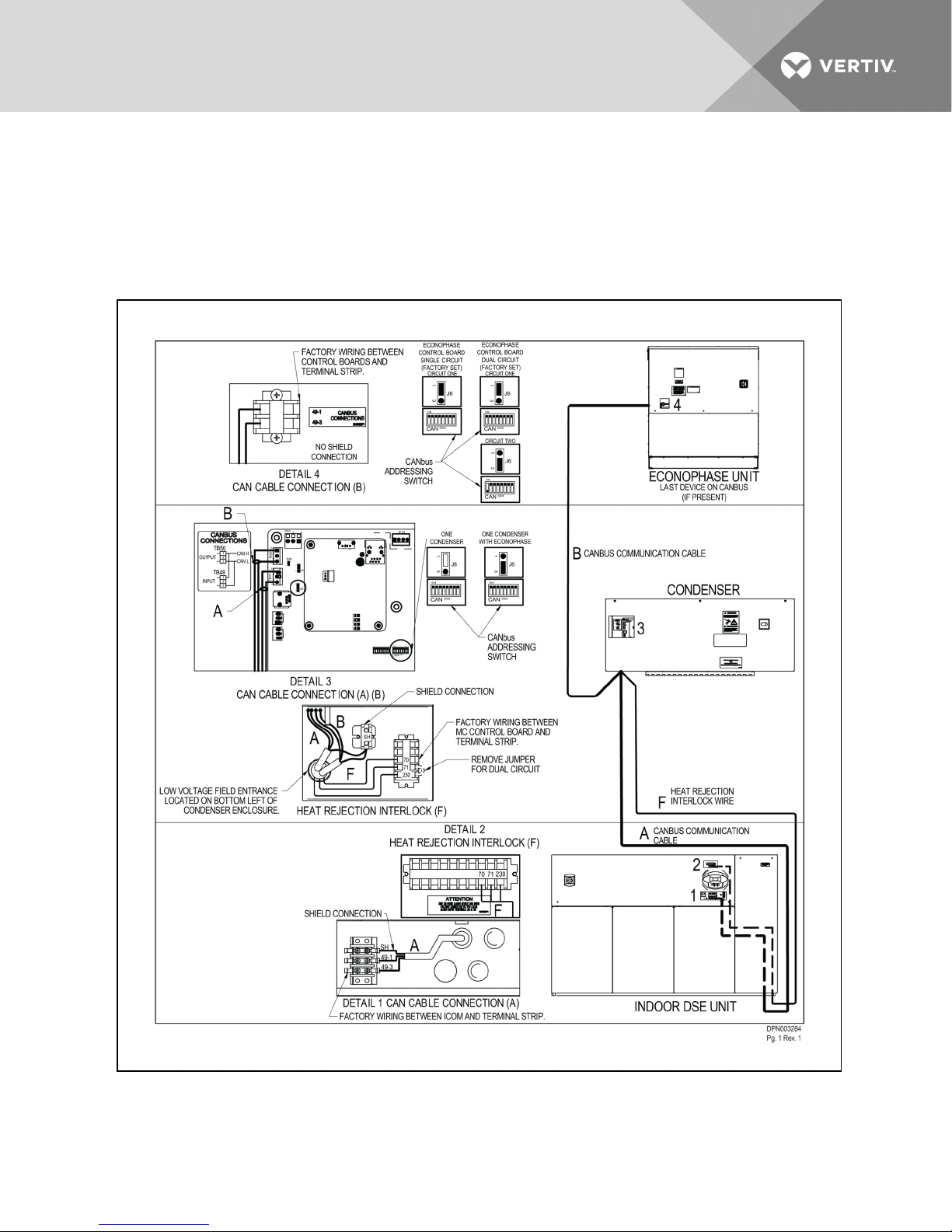
Figure 4.2 CANbus communication and interlock connections
betweenaLiebertDSE,onepremiumLiebert MC and a Liebert EconoPhase
CANbus Cable: A, B
Interlock Wire: F
Vertiv | Liebert® MC™ Installer/User Guide | 44
Page 45
See Low-voltage Control Wiring—CANbus Communication andInterlock Connections on page43 for
cable and wire requirements.
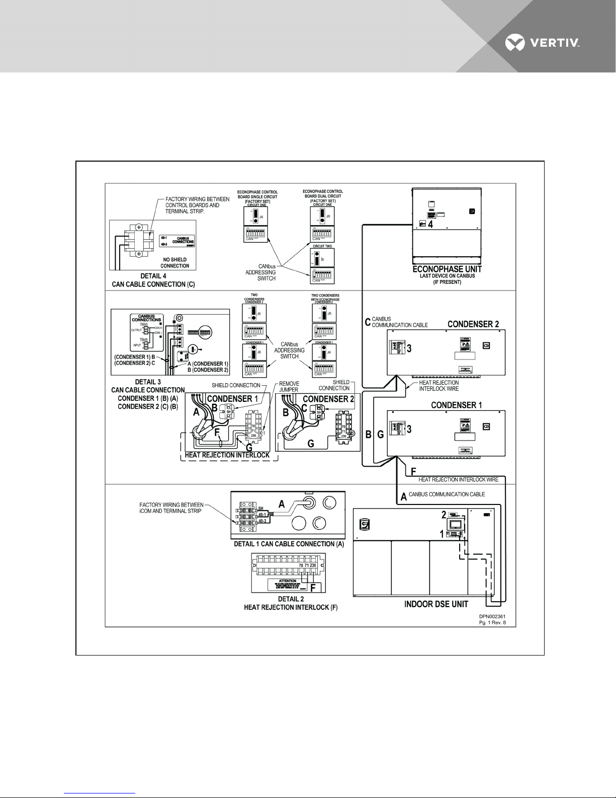
Figure 4.3 CANbus communications and interlock connections
betweenaLiebertDSE,twoLiebertMCcondensers and a Liebert EconoPhase
CANbus Cable: A, B, C
Interlock Wire: F, G
See Low-voltage Control Wiring—CANbus Communication andInterlock Connections on page43 for
cable and wire requirements.
Vertiv | Liebert® MC™ Installer/User Guide | 45
Page 46
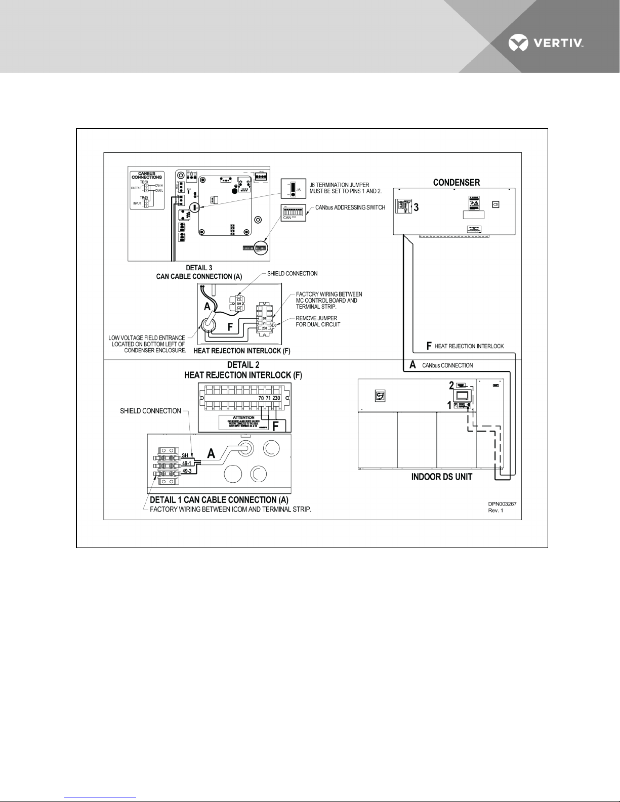
Figure 4.4 CANbus communications and interlock connections between a Liebert DS
andLiebertMCcondenser
CANbus Cable: A
Interlock Wire: F
See Low-voltage Control Wiring—CANbus Communication andInterlock Connections on page43 for
cable and wire requirements.
Vertiv | Liebert® MC™ Installer/User Guide | 46
Page 47
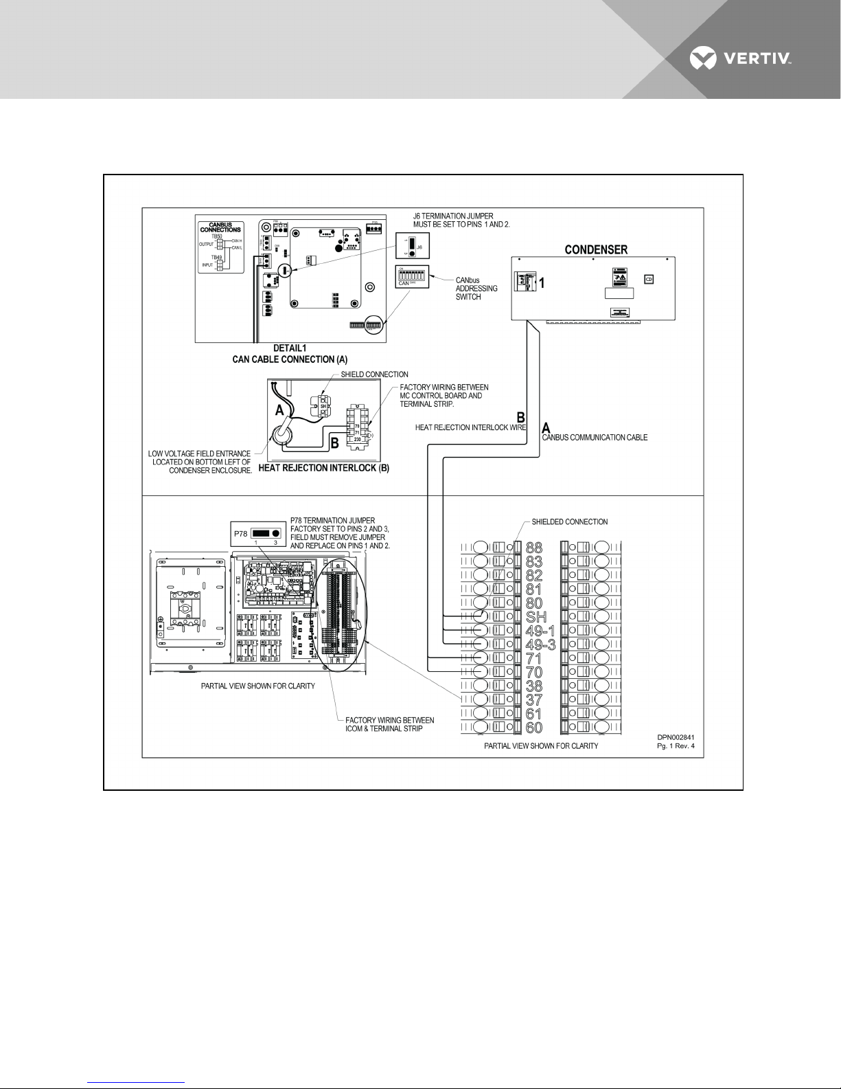
Figure 4.5 CANbus communication and interlock connections between a Liebert CRV 600mm (24in.)
andaLiebert MC premium condenser
CANbus Cable: A
Interlock Wire: B
See Low-voltage Control Wiring—CANbus Communication andInterlock Connections on page43 for
cable and wire requirements.
Vertiv | Liebert® MC™ Installer/User Guide | 47
Page 48
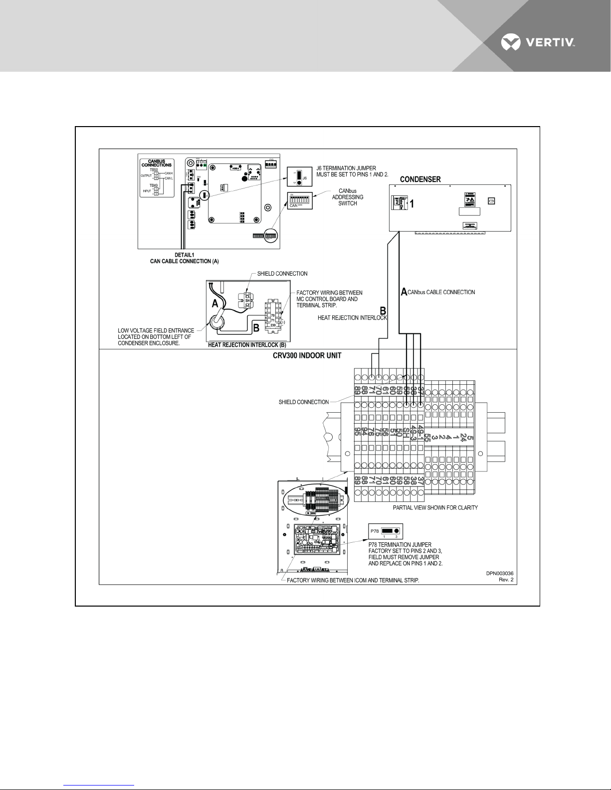
Figure 4.6 CANbus communications and interlock connection between Liebert CRV 300mm (12in.)
andaLiebert MC premium condenser
CANbus Cable: A
Interlock Wire: B
See Low-voltage Control Wiring—CANbus Communication andInterlock Connections on page43 for
cable and wire requirements.
Vertiv | Liebert® MC™ Installer/User Guide | 48
Page 49
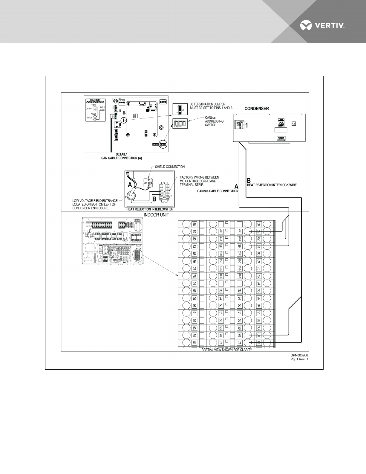
Figure 4.7 CANbus communication and interlock connection between Liebert PDX
andaLiebertMCpremium condenser
™
CANbus Cable: A
Interlock Wire: B
See Low-voltage Control Wiring—CANbus Communication andInterlock Connections on page43 for
cable and wire requirements.
Vertiv | Liebert® MC™ Installer/User Guide | 49
Page 50
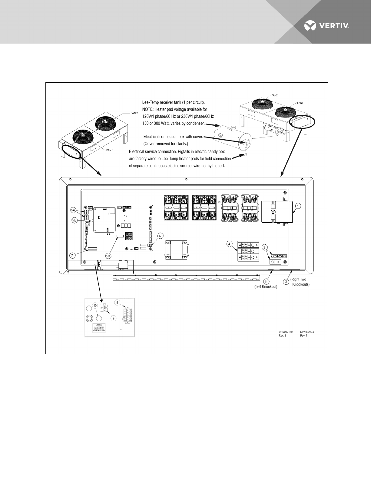
4.2.1 Electrical Field Connection Descriptions
Figure 4.8 Typical connections, Premium Efficiency Control
Key Electrical Details—Typical Connections, PremiumEfficiency Control
Source: DPN002169, Rev. 7 and DPN002374, Rev. 6. The following numbered items correspond to the
callouts in Figure 4.8 above.
1. Three-Phase Electrical Service—Terminals are on the top of the disconnect switch for one-fan
and two-fan units. Terminals are on the bottom of the disconnect switch for three-fan and fourfan units. Three-phase service not by Vertiv™. See NOTICE on page43.
2. Earth Ground—Field lug terminal for earth ground connection. Ground terminal strip for fan
motor ground connection.
Vertiv | Liebert® MC™ Installer/User Guide | 50
Page 51

3. Primary High-Voltage Entrance—Two knockouts, each 7/8” (22.2mm) diameter, located at the
bottom of the enclosure.
4. SPD Field Connection Terminals—High-voltage surge protective device (SPD) terminals. SPD
is an optional device.
5. CANbus Terminal Connections—Field terminals for CANbus cable connection.
• 5A is the CANbus connectors
TB49-1 is the input terminal for CANbus high.
TB49-3 is the input terminal for CANbus low.
TB50-1 is the output terminal for CANbus high.
TB50-3 is the output terminal for CANbus low.
Each CANbus cable shield is connected to terminal “SH;” seeCANbus Shield Terminal—
Terminal for field shield connection of the CANbus field-supplied cables. The shield of
CANbus field-supplied cables must not be connected to ground at the condenser. below
below.
• 5B is the “END OF LINE” jumper.
• 5C is the CANbus “DEVICE ADDRESS DIP SWITCH.” CANbus cable not by Vertiv™. See
requirements in Notes on Electrical Connections on page43.
6. Remote Unit Shutdown—Replace exiting jumper between Terminals TB38-1 and TB38-2 with
field-supplied, normally closed switch having a minimum 75VA, 24VAC rating. Use fieldsupplied Class1 wiring. (This is an optional feature.)
7. Alarm Terminal Connections
a. Common Alarm Relay indicates when any type of alarm occurs. TB74-1 is common; TB74-
2 is normally open; and TB74-3 is normally closed. 1A 24VAC is the maximum load. Use
field-supplied Class1 wiring.
b. Shutdown Alarm Relay indicates when condenser loses power or when a critical alarm has
occurred that shuts down the condenser unit. TB74-4 is common; TB74-5 is normally
open; and TB74-6 is normally closed. 1 Amp 24VAC is the maximum load. Use
field-supplied Class1 wiring.
8. Indoor Unit Interlock and SPD Alarm Terminals
a. On any call for compressor operation, normally open contact is closed across Terminals
70 and 71 for Circuit 1 and normally open contact is closed across Terminals 70 and 230
for Circuit 2 from indoor unit.
b. During SPD alarm, normally open contact is closed across Terminals 12 and 13. (SPD is an
optional device.)
9. CANbus Shield Terminal—Terminal for field shield connection of the CANbus field-supplied
cables. The shield of CANbus field-supplied cables must not be connected to ground at the
condenser.
10. Primary Low-Voltage Entrance—One knockout, 7/8” (22.2mm) diameter, that is free for
customer low-voltage wiring.
11. SPD entrance—One knockout, 7/8” (22.2mm) diameter at the bottom of the enclosure.
(High-voltage surge protective device is optional.)
Vertiv | Liebert® MC™ Installer/User Guide | 51
Page 52

This page intentionally left blank.
Vertiv | Liebert® MC™ Installer/User Guide | 52
Page 53
5 PIPING
WARNING! Risk of explosive discharge from high-pressure refrigerant. Can cause equipment
damage, injury or death.
Relieve pressure before working with or cutting into piping.
WARNING! Risk of refrigerant system rupture or explosion from overpressurization. Can cause
equipment damage, injury or death.
Local building and plumbing codes may require that a fusible plug or other type of pressure
relief device be installed in the system. Do not install a shutoff valve between the compressor
and the field-installed relief device.
Consult local building and plumbing codes for installation requirements of additional pressure
relief devices when isolation valves are installed as shown in Figure 5.1 on page55. Do not
isolate any refrigerant circuits from over-pressurization protection.
NOTE: POE (polyol ester) oil, required with R-407C/R-410A and used with some R-22 systems, is much
more hygroscopic than mineral oils. This means that POE oil absorbs water at a much faster rate when
exposed to air than previously used mineral oils. Because water is the enemy of a reliable refrigeration
system, extreme care must be used when opening systems during installation or service. If water is
absorbed into the POE oil, it will not be easily removed and will not be removed through the normal
evacuation process. If the oil is too wet, it may require an oil change. POE oils also have a property that
makes them act as a solvent in a refrigeration system. Maintaining system cleanliness is extremely
important because the oil will tend to bring any foreign matter back to the compressor or plug the
microchannel coil. Always use a flow of dry nitrogen when brazing.
5.1 Piping Guidelines
Indoor units and condensers both ship with holding charges of inert gas. Do not vent the condenser until
all refrigerant piping is in place, ready for connection to indoor unit and condenser.
• Use copper piping with a brazing alloy with a minimum temperature of 1350°F (732°C), such as
Sil-Fos. Avoid soft solders such as 50/50 or 95/5.
• Use a flow of dry nitrogen through the piping during brazing to prevent formation of copper
oxide scale inside the piping. When copper is heated in the presence of air, copper oxide forms.
POE oil will dissolve these oxides from inside the copper pipes and deposit them throughout
the system, clogging filter driers and affecting other system components.
• A pure dry nitrogen flow of 1-3 ft3/min (0.5-1.5 l/s) inside the pipe during brazing is sufficient to
displace the air. Control the flow using a suitable metering device.
• Ensure that the tubing surfaces to be brazed are clean and that the ends of the tubes have
been carefully reamed to remove any burrs.
• Ensure that all loose material has been cleaned from inside the tubing before brazing.
• Protect all refrigerant line components within 18" (460mm) of the brazing site by wrapping
them with wet cloth or suitable heat sink compound.
• Isolate piping from building using vibration isolating supports.
Vertiv | Liebert® MC™ Installer/User Guide | 53
Page 54

• Refer to the indoor unit’s user manual for appropriate piping sizes.
• Install traps on the hot gas (discharge) lines at the bottom of any rise over 5 feet high. If the rise
exceeds 25 feet (7.5m), then install a trap in 20 foot (6m) increments or evenly divided.
• Pitch horizontal hot gas piping down at a minimum rate of 1/2” per 10 ft. (42mm per 10m) so
that gravity will aid in moving oil in the direction of refrigerant/oil flow.
• Consult factory if Liebert Lee-Temp™ condenser is below the evaporator or if a condenser not
equipped with Liebert Lee-Temp is more than 15 ft (4.6m) below the evaporator.
• Consult factory if piping run exceeds 150 feet (46m) equivalent length on traditional R-407C
DX units.
• Consult factory if piping run exceeds 300 feet (91m) equivalent length on traditional R-410A
DX units.
• Consult factory if piping run exceeds 300 feet (91m) actual length or 450 feet (137m)
equivalent length on units installed with Liebert EconoPhase units.
• Keep piping clean and dry, especially on units with POE oil (R-407C, R-410A or R-22
refrigerant).
• Avoid piping runs through noise-sensitive areas.
• Do not run piping directly in front of indoor unit discharge air stream.
• Refrigerant oil – do not mix oil types or viscosities. Consult indoor unit for refrigerant type and
oil requirements.
NOTE: Failure to use compressor oils recommended by compressor manufacturer will void compressor
warranty. Consult Vertiv™ or the compressor manufacturer for further recommendations or if you have
questions about compressor oils.
Refer to ASHRAE Refrigeration Handbook for general good practices for refrigeration piping. The
Liebert indoor cooling unit has a factory-installed high-pressure safety switch in the high side
refrigerant circuit. A pressure relief valve is provided with Liebert Lee-Temp™ receivers. A fusible plug is
factory installed in the Liebert DSE™ receivers. Consult local building codes to determine if condensers
without receivers will require field-provided pressure relief devices. A fusible plug kit is available for
field installation.
Vertiv | Liebert® MC™ Installer/User Guide | 54
Page 55
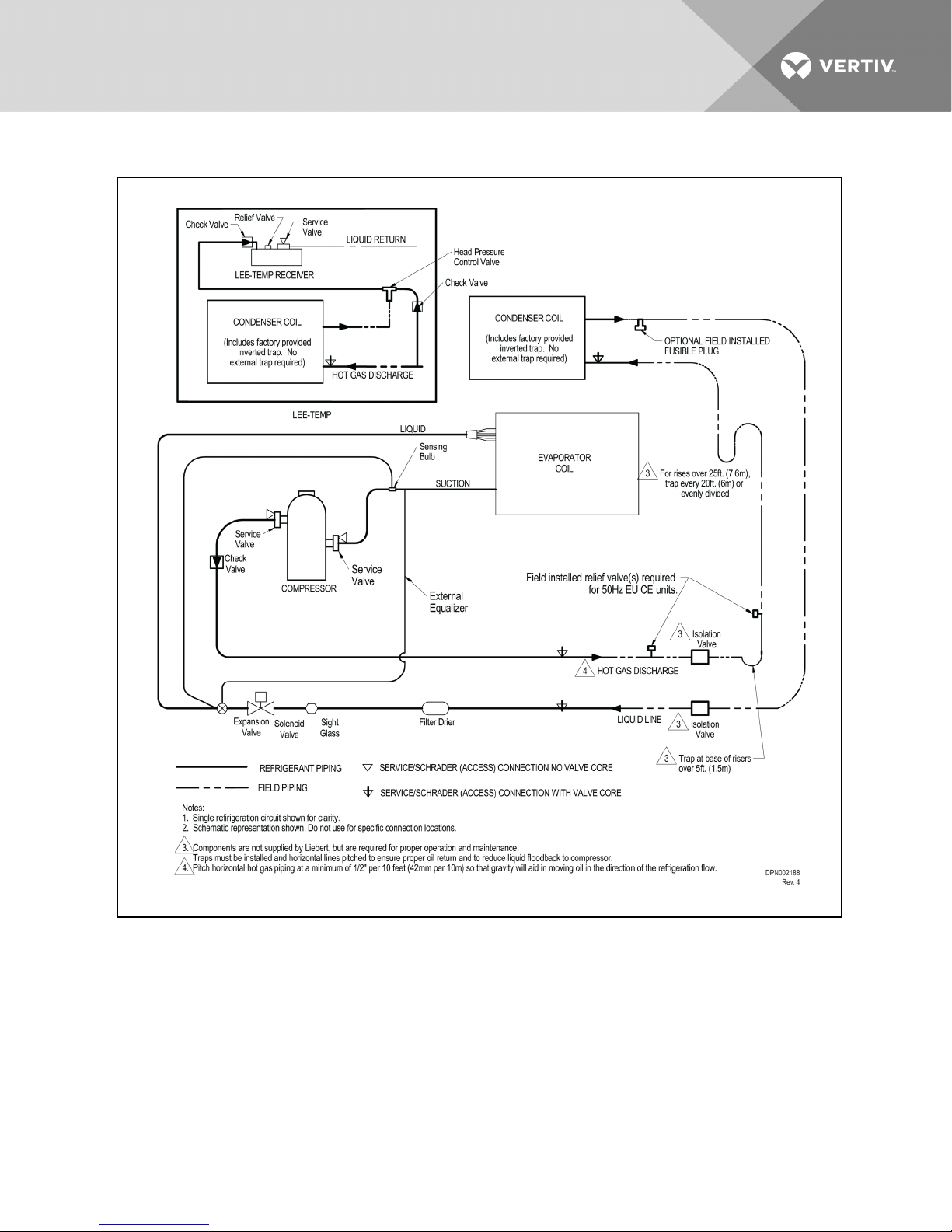
Figure 5.1 Piping schematic—DX systems
Vertiv | Liebert® MC™ Installer/User Guide | 55
Page 56
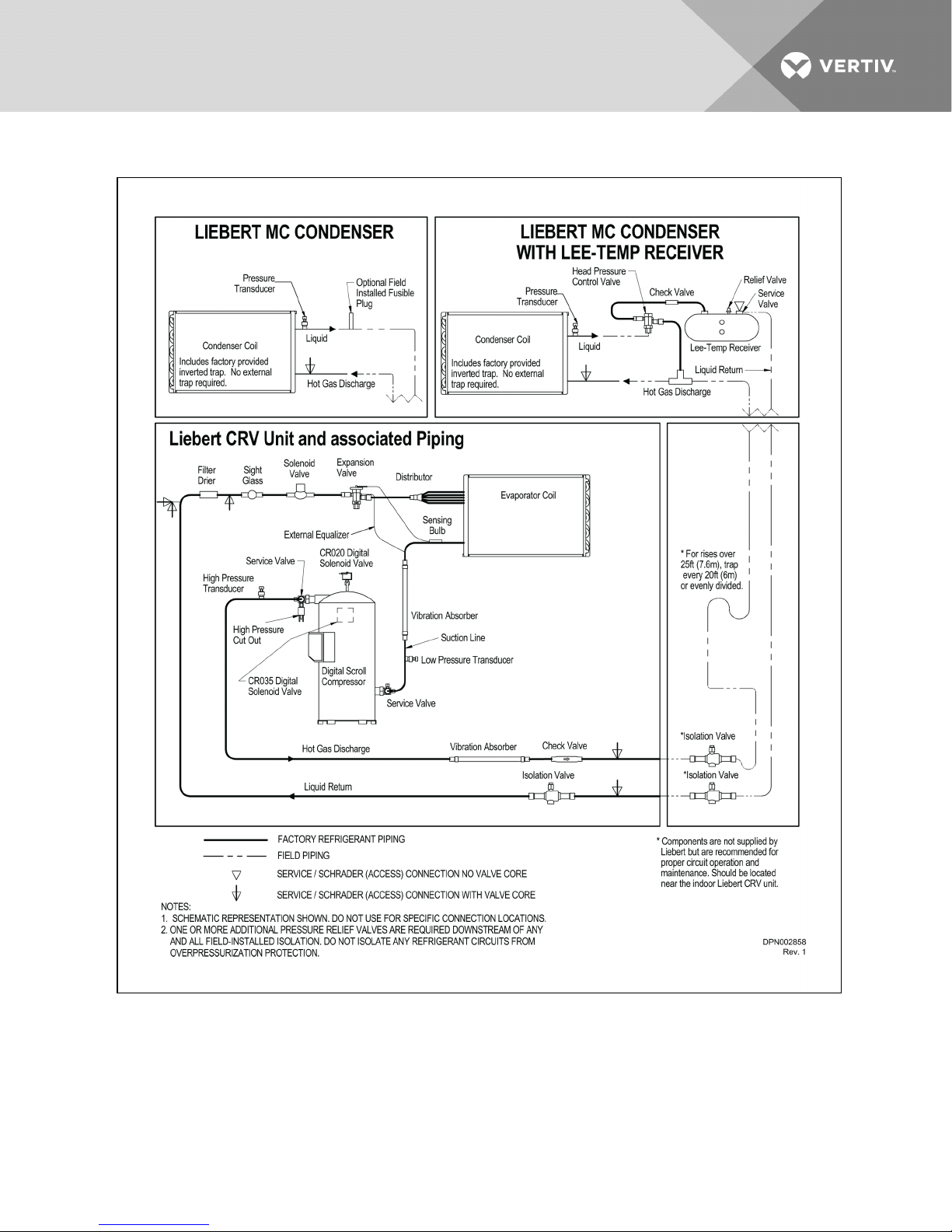
Figure 5.2 Piping schematic—CRV 600mm (24 in.) DX systems
Vertiv | Liebert® MC™ Installer/User Guide | 56
Page 57
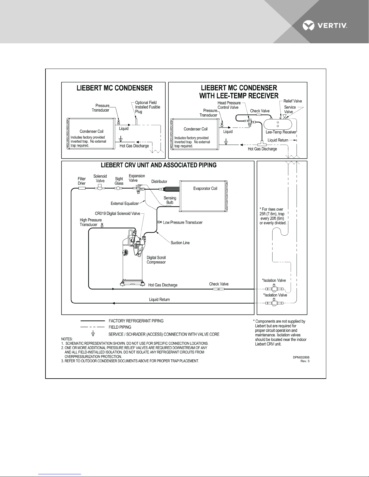
Figure 5.3 Piping schematic—CRV300mm (12in.) DX systems
Vertiv | Liebert® MC™ Installer/User Guide | 57
Page 58
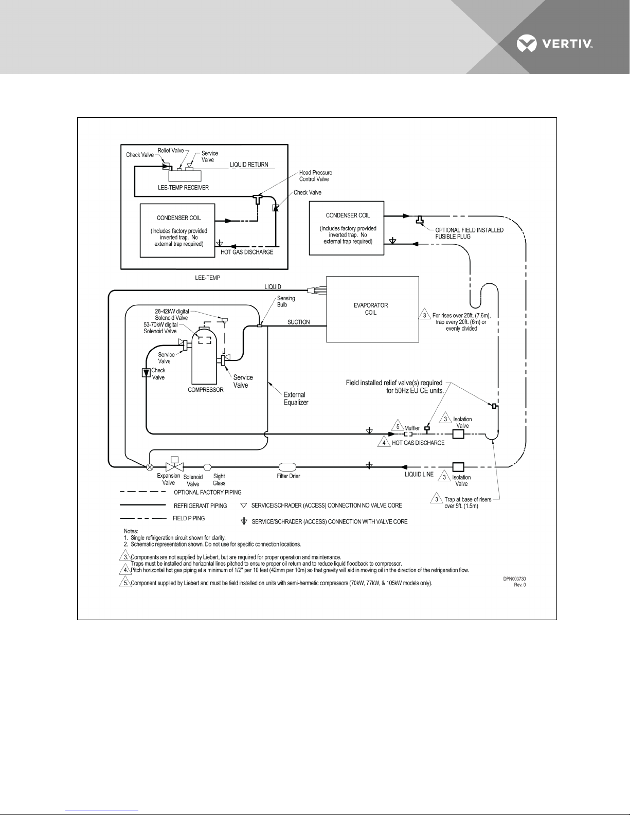
Figure 5.4 Piping schematic—DS DX systems
Vertiv | Liebert® MC™ Installer/User Guide | 58
Page 59
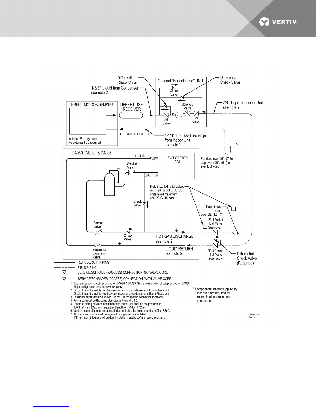
Figure 5.5 Piping schematic—Liebert DSE™, air-cooled DA050, DA080 and DA085 models
Vertiv | Liebert® MC™ Installer/User Guide | 59
Page 60
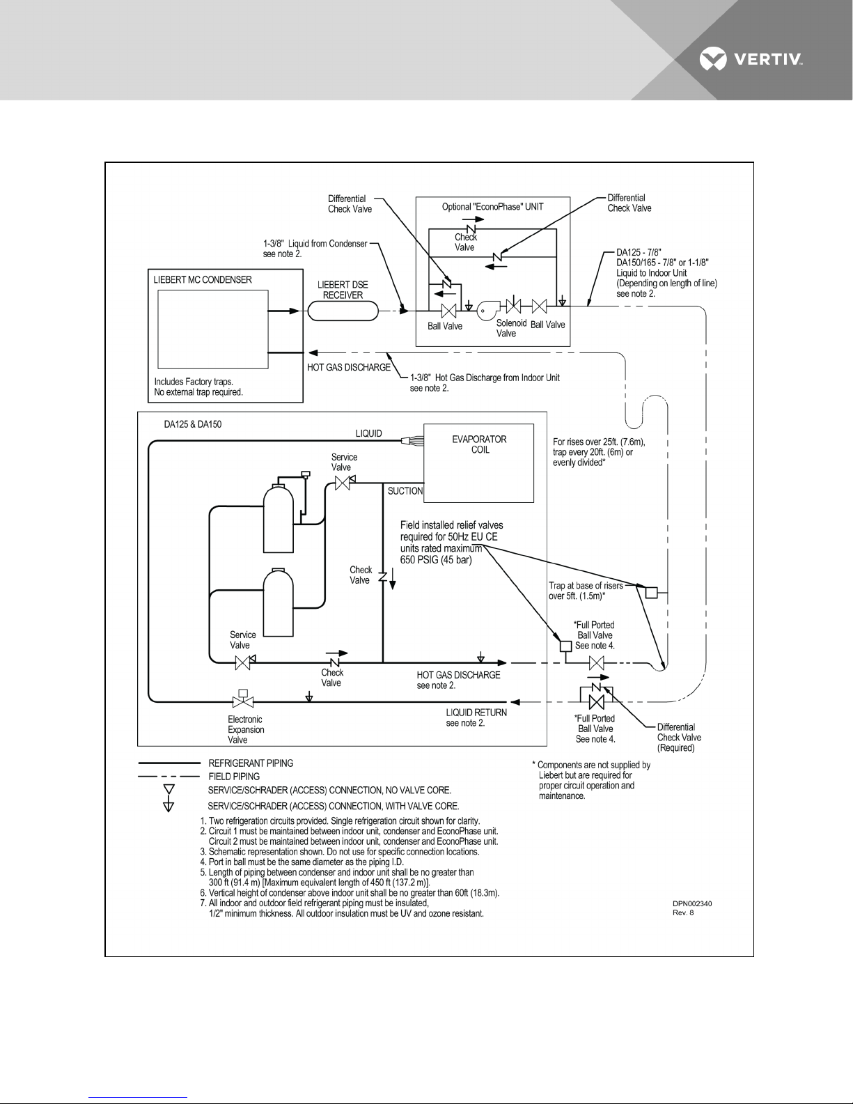
Figure 5.6 Piping schematic—Liebert DSE™, air-cooled DA125, DA150 and DA165 models
Vertiv | Liebert® MC™ Installer/User Guide | 60
Page 61

5.2 Field Piping Guidelines
One discharge line and one liquid line must be field-installed for each circuit of the indoor unit and the
outdoor condenser(s). Dual circuit condensers are available for most dual circuit indoor unit applications.
Refer to Figure 5.1 on page55 throughCondenser piping for single-circuit condensers (with Liebert Lee-
Temp™) on page63 for additional field-installed piping needed at the condenser. This piping is needed
for proper system performance and for installation/interconnecting receivers and head pressure control
valves for Liebert Lee-Temp™ systems.
NOTE: Keep the evaporator unit and condenser closed with their factory charge of inert gas while all
field piping is installed. Keep the field piping clean and dry during installation, and do not allow it to
stand open to the atmosphere.
When all the field interconnecting piping is in place, vent the condenser’s inert gas charge and connect
to the field piping. Finally, vent the evaporator unit’s charge of inert gas and make its piping connection
last.
Follow all proper brazing practices, including a dry nitrogen purge to maintain system cleanliness.
The condenser connection pipes must be wrapped with a wet cloth to keep the pressure and
temperature sensors cool during any brazing.
Vertiv | Liebert® MC™ Installer/User Guide | 61
Page 62
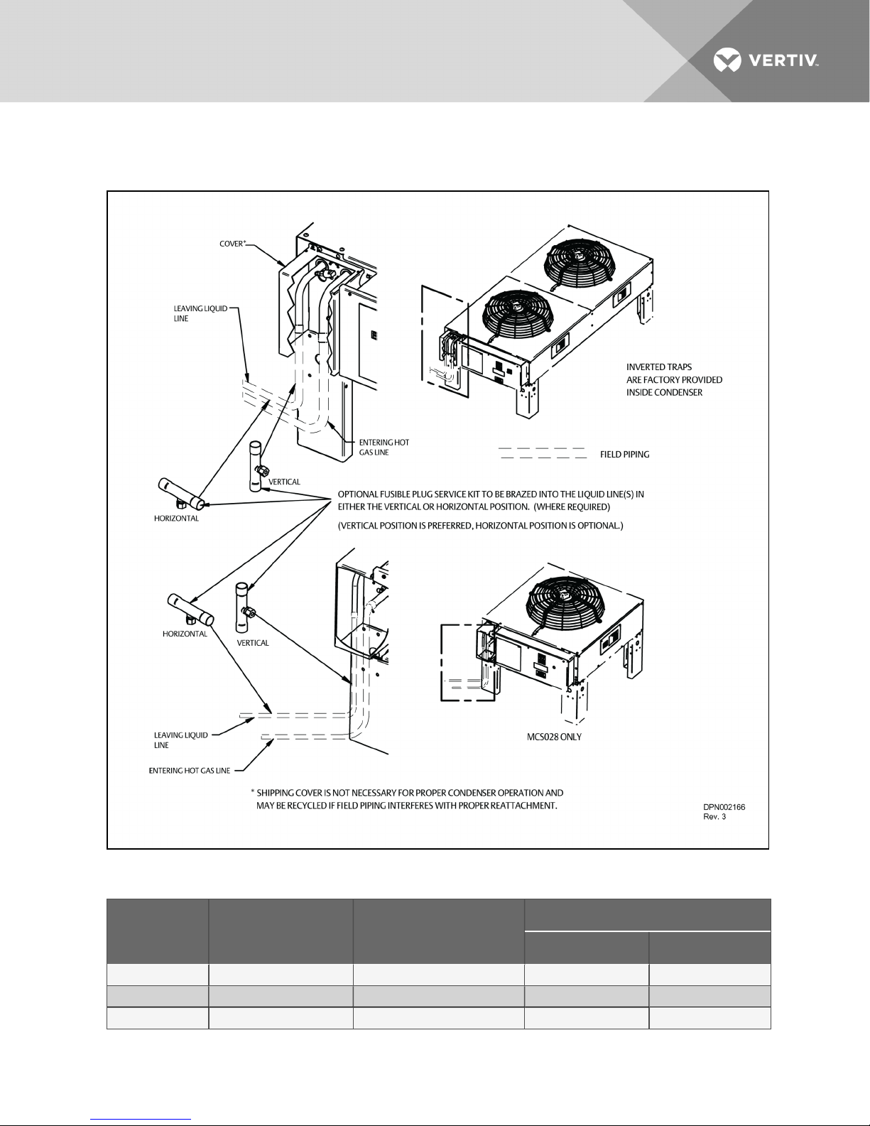
5.2.1 Field Piping Guidelines foraLiebertDXSystemandLiebertMCCondenser
Figure 5.7 Liebert MC Condenser piping—Single-circuit, 1-, 2-, 3- and 4-fan units
Table 5.1 Liebert MC Condenser piping sizes—Single-circuit units
Model No. Number of Fans Condenser Circuits
MCS028 1 1 7/8 5/8
MCM040 1 1 7/8 5/8
MCM080 2 1 1-1/8 7/8
Vertiv | Liebert® MC™ Installer/User Guide | 62
Connection Sizes, OD, in (mm)
Hot Gas L ine Liquid L ine
Page 63
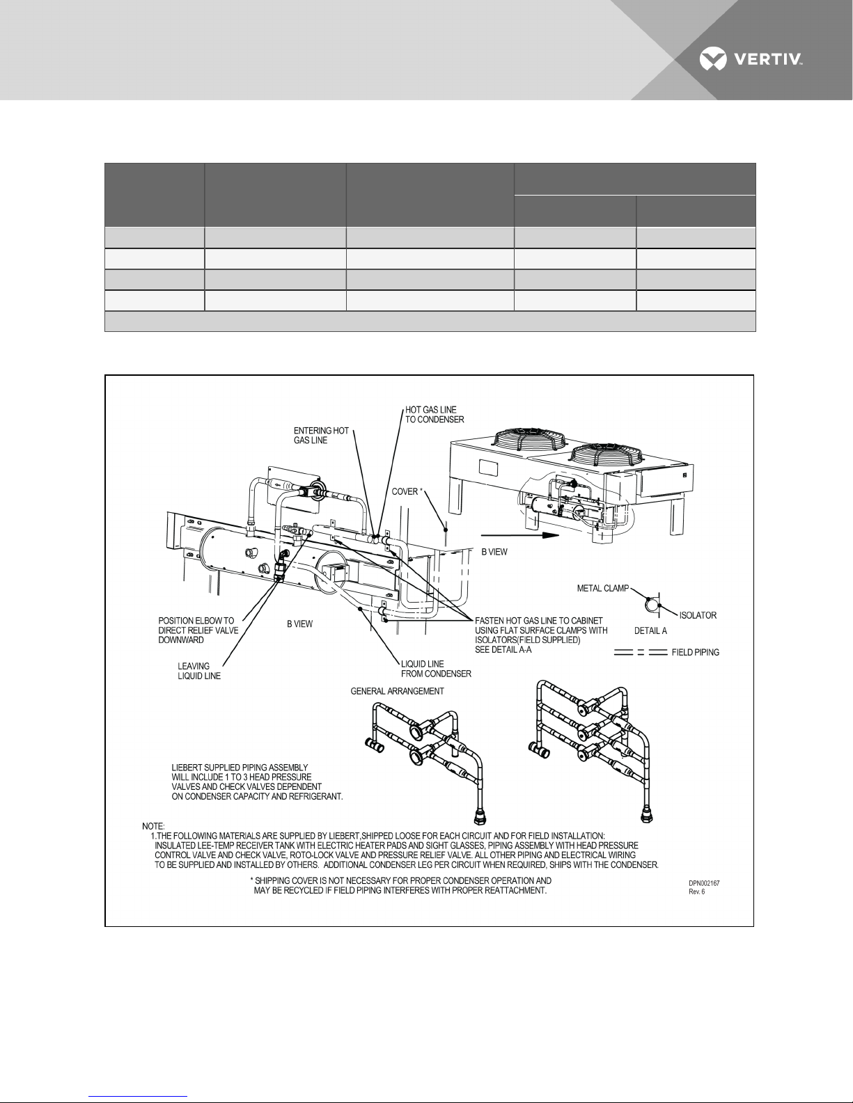
Table 5.1 Liebert MC Condenser piping sizes—Single-circuit units (continued)
Connection Sizes, OD, in (mm)
Model No. Number of Fans Condenser Circuits
Hot Gas L ine Liquid L ine
MCL055 1 1 1 -1/8 7/8
MCL110 2 1 1-3/8 1-1/ 8
MCL165 3 1 1-3/8 1-1/8
MCL220 4 1 1-5/8 1-3/8
Source: DPN002166, Rev. 3
Figure 5.8 Condenser piping for single-circuit condensers (with Liebert Lee-Temp™)
Vertiv | Liebert® MC™ Installer/User Guide | 63
Page 64
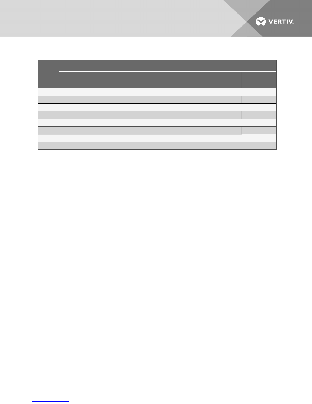
Table 5.2 Condenser piping connection sizes—Single-circuit condensers with Liebert Lee-Temp
Condenser Connections, OD, In Liebert Lee-Temp Connections
Model #
Hot Gas Liquid Hot Gas Tee IDS, In. Liquid Line to Liebert Lee-TempValve, OD S, In.
MCS028 7/8 5/8 7/8 5/8 5/8
MCM040 7/8 5/8 7/8 5/8 5/8
MCM080 1-1/8 7/8 1 -1/8 7/8 1-1/8
MCL055 1-1/8 7/8 1 -1/8 7/8 7/8
MCL110 1-3/ 8 1 -1/8 1-3/8 1-1/8 1-1/8
MCL165 1-3/8 1-1/8 1-3/8 1-1/ 8 1-1/8
MCL220 1-5/8 1 -3/8 1- 5/8 1-3/8 1 -3/8
Source: DPN002167, Rev. 6
Receiver Out
Rotalock, IDS, In.
Vertiv | Liebert® MC™ Installer/User Guide | 64
Page 65
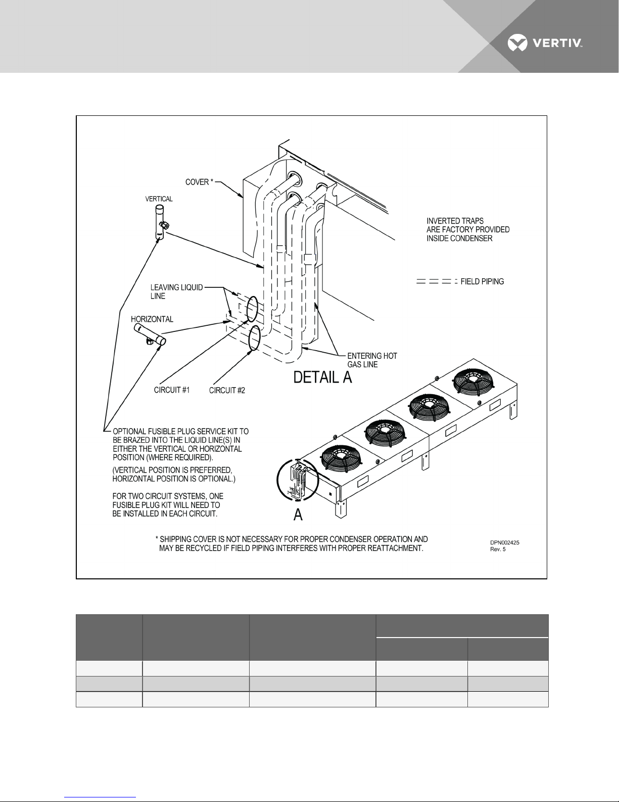
Figure 5.9 Piping: dimensions—Dual circuit two-fan and four-fan units
Table 5.3 Piping: dimensions—Dual-circuit, two-fan and four-fan units
Model # Number of Fans Condenser C ircuits
MCS056 2 2 7/8 5/8
MCM080 2 2 7/8 5/8
MCL110 2 2 1-1/8 7/8
Vertiv | Liebert® MC™ Installer/User Guide | 65
Connection Sizes, OD, in
Hot Gas L ine Liquid Line
Page 66
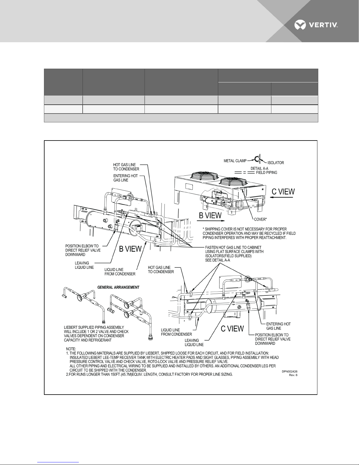
Table 5.3 Piping: dimensions—Dual-circuit, two-fan and four-fan units (continued)
Connection Sizes, OD, in
Model # Number of Fans Condenser C ircuits
Hot Gas L ine Liquid Line
MCM160 4 2 1 -1/8 7/ 8
MCL220 4 2 1-3/8 1-1/ 8
Source: DPN002425, Rev. 5
Figure 5.10 Piping: Dimensions with Liebert Lee-Temp™—Dual circuit condensers
Vertiv | Liebert® MC™ Installer/User Guide | 66
Page 67
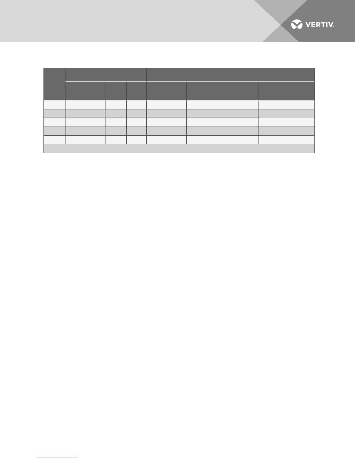
Table 5.4 Condenser piping connection sizes—Dual-circuit condensers with Liebert Lee-Temp
Condenser Connections, OD.In Liebert Lee-Temp Connections
Model
#
MCS056 2 7/8 5/8 7/ 8 5/8 5/8
MCM080 2 7/8 5/8 7/8 5/8 5/8
MCL110 2 1-1/8 7/8 1-1 /8 7/8 78
MCL160 2 1-1/8 7/ 8 1-1/ 8 7/8 1-1/ 8
MCL220 2 1 -3/8 1 -1/8 1-3/8 1-1/8 1-1/ 8
Source: DPN002426, Rev. 6
Condenser
Circuits
Hot
Gas
Liquid
Hot Gas Tee IDS
In.
Liquid Lineto Lee-Temp Valve
ODS, In.
Receiver Out Rotalock
IDS In.
Vertiv | Liebert® MC™ Installer/User Guide | 67
Page 68
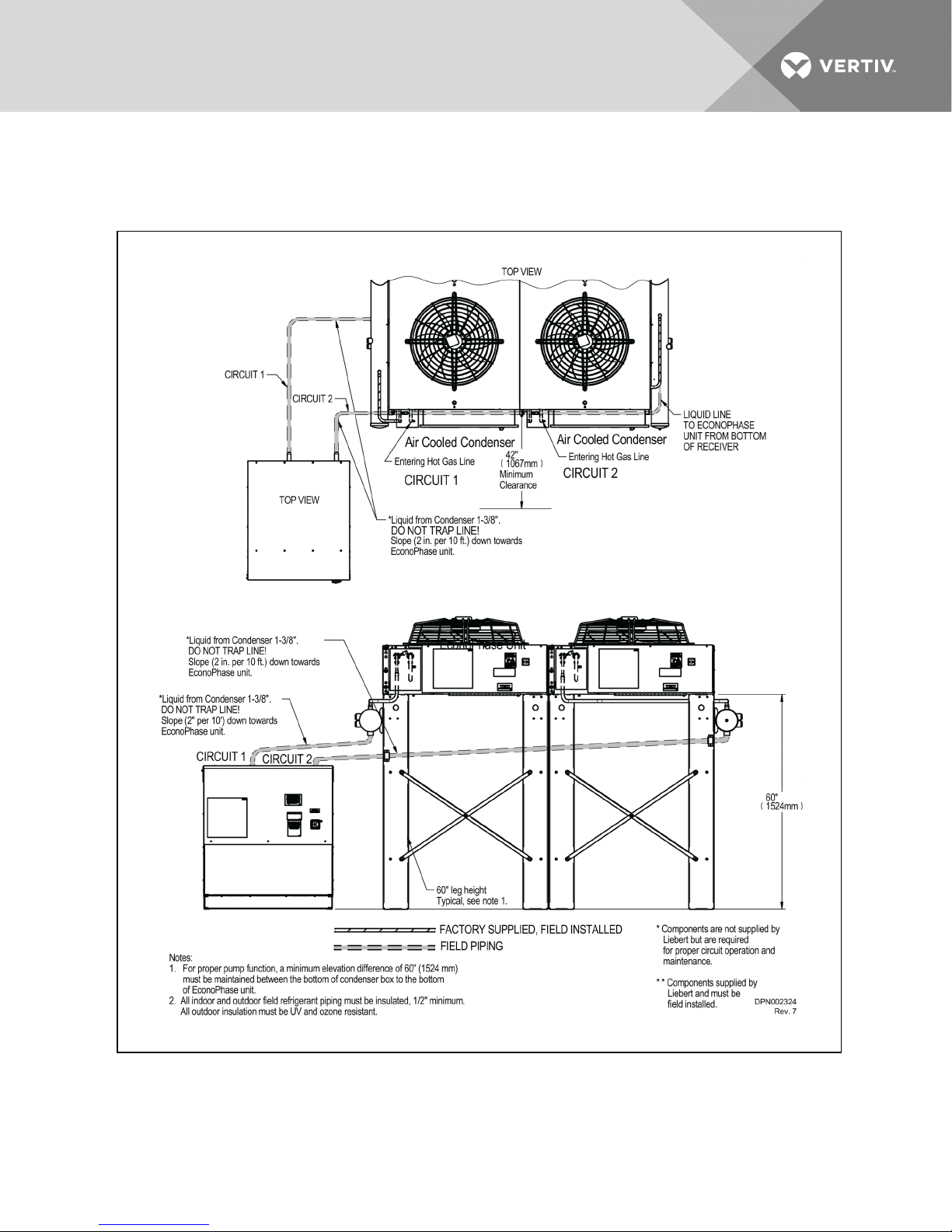
5.2.2 Field Piping Guidelines foraLiebertDSEandLiebertPremiumMCCondenser
Figure 5.11 Condenser and Liebert EconoPhase™, typical unit arrangement diagram layout
fordual-circuitsystem
Vertiv | Liebert® MC™ Installer/User Guide | 68
Page 69
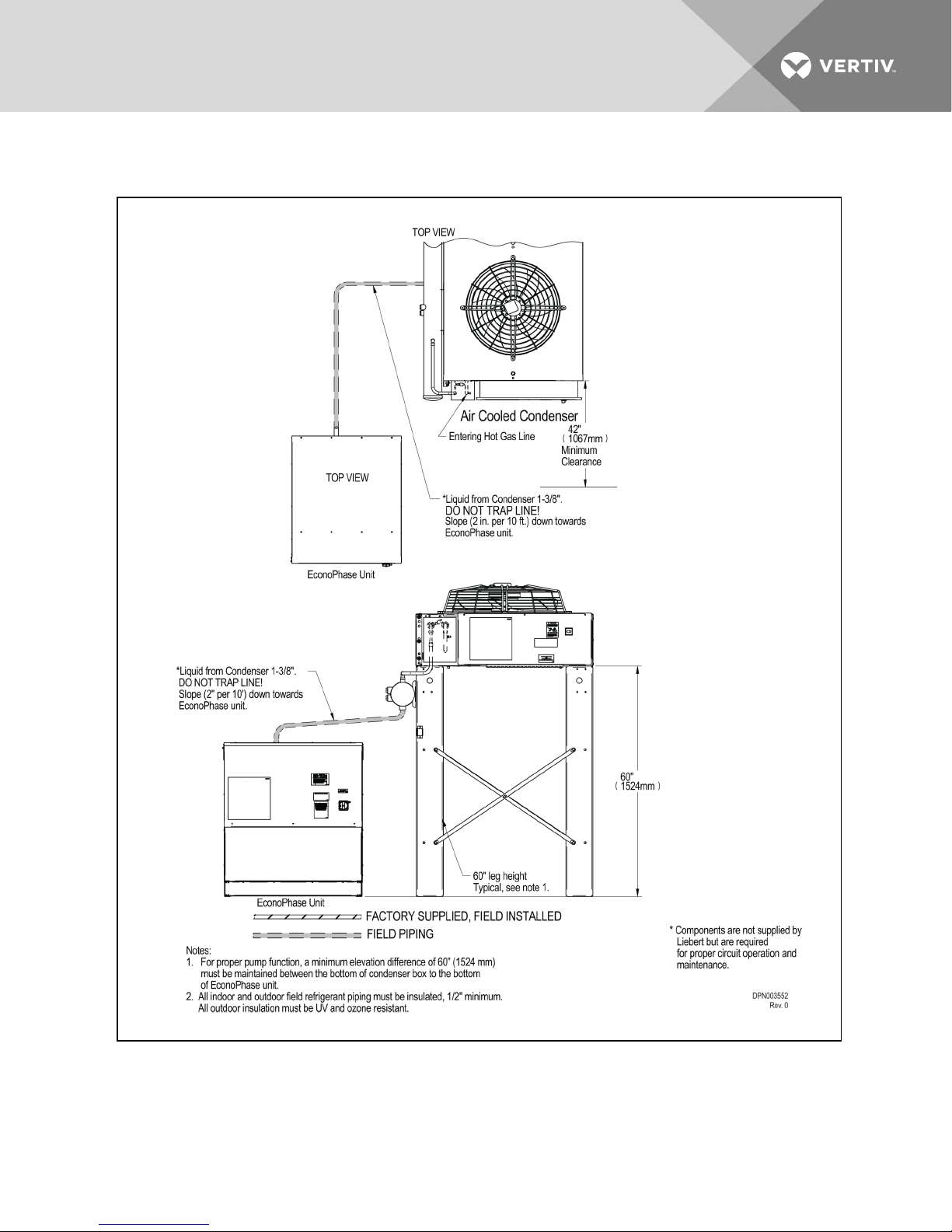
Figure 5.12 Condenser and Liebert EconoPhase™, typical unit arrangement diagram layout
forsingle-circuitsystem
Vertiv | Liebert® MC™ Installer/User Guide | 69
Page 70
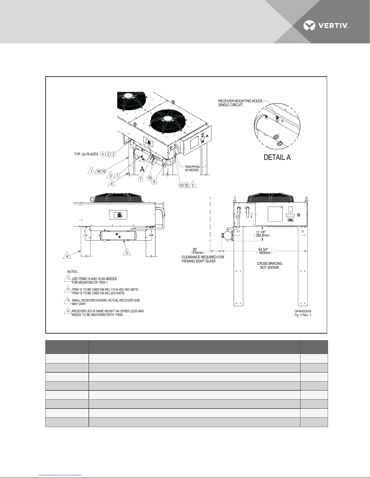
Figure 5.13 Typical receiver Liebert DSE mounting, MCL110, MCL165 and MCL220 single-circuit
condenser, left-sidecondenser outlet receiver
Item No. Description Qty
1 Receiver andBracket As sembly 1
2 Cap Scr ew HXDIN933M8-1.25X25A2 8
3 Fender Washer DIN9021 M8X24 A2 12
4 Lock NutHex NYL INSR M8 8
7 90° Elbow FTGXFTG 7/8” Copper 1
8 Copper Formed Tube 1 -1/8” 1
12 CouplingCopper 1-1/8” 1
13 Reducer Copper CXC 1 -3/8”x1-1/8” 1
Vertiv | Liebert® MC™ Installer/User Guide | 70
Page 71
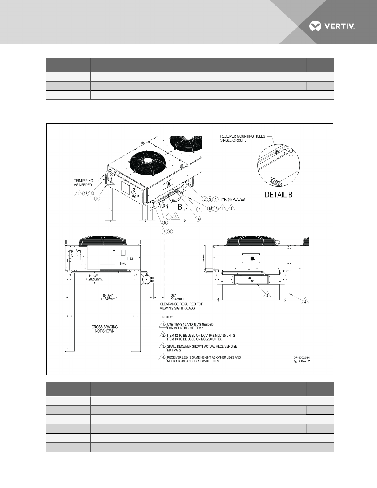
Item No. Description Qty
14 Reducer Copper CXC1 -1/8”x7/8” 1
15 Support Leg 1
16 Fastener Assembly: Cap Screw, Lock Washer, Fender Washer 4
Figure 5.14 Typical receiver Liebert DSE mounting, MCL110, MCL165 and MCL220 single-circuit
condenser, right-side condenser outlet receiver
Item No. Description Qty
1 Receiver andBracket As sembly 1
2 Cap Scr ew HXDIN933M8-1.25X25A2 8
3 Fender Washer DIN9021 M8X24 A2 12
4 Lock NutHex NYL INSR M8 8
5 ClampOmega 7/8” 7
6 Screw SD HWH YZ 10-16 x 5/8 2
Vertiv | Liebert® MC™ Installer/User Guide | 71
Page 72
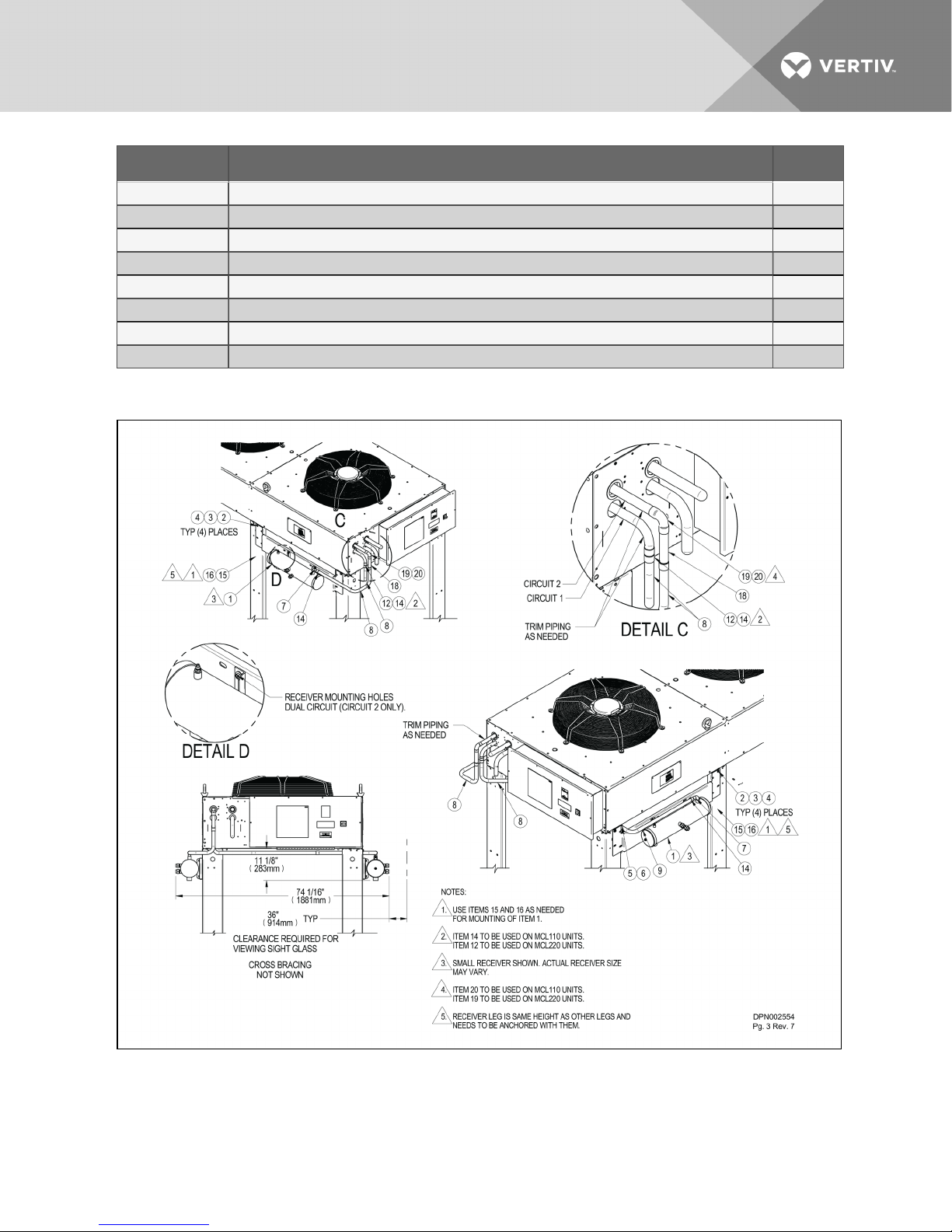
Item No. Description Qty
7 90° Elbow FTGXFTG 7/8” CU 1
8 Copper Formed Tube 1 -1/8” 1
9 Copper Formed Tube 1-1/8” 2
12 CouplingCopper 1-1/8” 1
13 Reducer Copper CXC 1 -3/8”x1-1/8” 1
14 Reducer Copper CXC1 -1/8”x7/8” 2
15 Support Leg 1
16 Fastener Assembly: Cap Screw, Lock Washer, Fender Washer 4
Figure 5.15 Typical receiver Liebert DSE mounting, MCL110 and MCL220 dual-circuit condenser,
twooutlet receivers
Vertiv | Liebert® MC™ Installer/User Guide | 72
Page 73
Item No. Description Qty
1 Receiver andBracket As sembly 2
2 Cap Scr ew HXDIN933M8-1.25X25A2 12
3 Fender Washer DIN9021 M8X24 A2 20
4 Lock NutHex NYL INSR M8 12
5 ClampOmega 7/8” 1
6 Screw SD HWH YZ 10-16 x 5/8 2
7 90° Elbow FTGXFTG 7/8” Copper 2
8 Copper Formed Tube 1 -1/8” 2
9 Copper Formed Tube 1-1/8” 1
12 CouplingCopper 1-1/8” 1
14 Reducer Copper CXC1 -1/8”x7/8” 3
15 Support Leg 2
16 Fastener Assembly: Cap Screw, Lock Washer, Fender Washer 8
18 Copper Tube 1-1/8” Swaged 1
19 90° Elbow CXC 1-1/8” Copper 1
20 90° Elbow CXC 1 -1/8”X7/8” Copper 1
Vertiv | Liebert® MC™ Installer/User Guide | 73
Page 74
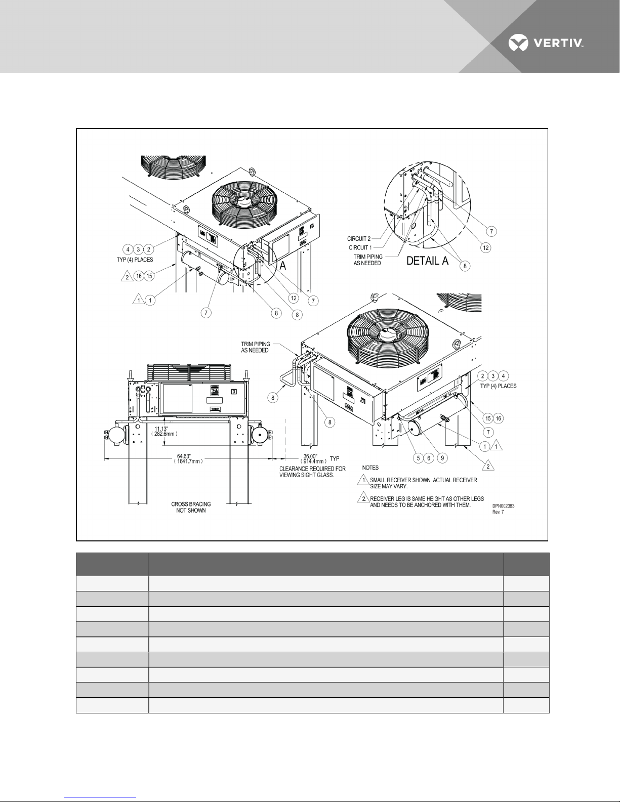
Figure 5.16 Typical receiver Liebert DSE mounting, MCM160 dual-circuit condenser,
twooutletreceivers
Item No. Description Qty
1 Receiver andBracket As sembly 2
2 Cap Scr ew HXDIN933M8-1.25X25A2 12
3 Fender Washer DIN9021 M8X24 A2 20
4 Lock NutHex NYL INSR M8 12
5 ClampOmega 7/8” 1
6 Screw SD HWH YZ 10-16 x 5/8 2
7 90° Elbow FTGXC7/8” Copper 3
8 Copper Formed Tube 7/8” 2
9 Copper Formed Tube 7/ 8” 1
Vertiv | Liebert® MC™ Installer/User Guide | 74
Page 75
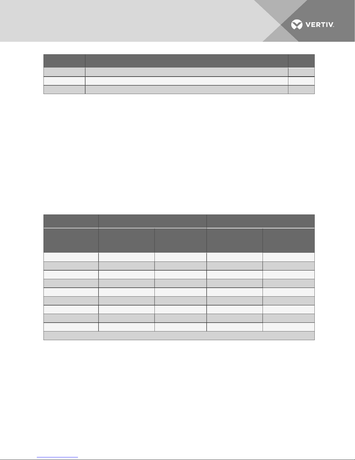
Item No. Description Qty
12 Copper Tube 7/8” Swaged 1
15 Support Leg 1
16 Fastener Assembly: Cap Screw, Lock Washer, Fender Washer 4
5.3 Refrigerant Planning Values
Planning for the refrigerant requirements of the completed system is the total of the charges from Indoor
Unit, Condenser (including Liebert Lee-Temp™ receiver, if used) and the interconnecting piping. Table 5.5
below, Table 5.6 on the next page, Table 5.8 on page78 and Table 5.9 on page80 provide the
approximate charge required for the condensers, recommended refrigerant pipe sizes and the
interconnecting piping. Consult indoor unit manuals for indoor unit charge requirements.
These values can be used for obtaining adequate refrigerant for the system, but should not be used for
final charging.
NOTE: Due to the much smaller coil volume, the performance, especially subcooling, of a LiebertMC
condenser is quite sensitive to the amount of refrigerant charge. Ensure that an accurate amount of
refrigerant charge is added.
Table 5.5 Refrigerant required, R-407C, approximate
Condenser Models Single Circuit, lb/circuit (kg/circuit) DualCircuit, lb/circuit (kg/circuit)
Approximate
R-407C
Refrigerant Needed
MCS028 2.2 (1.0) 23.1 ( 10.5) — —
MCS056 N/A N/ A 2.2 (1.0) 23.1 (10.5)
MCM040 3.0 (1.4) 23.9 (10.8) N/A N/A
MCM080 7.5 (3.4) 44 .5 (20.2) 3.0 (1.4) 23.9 ( 10.8)
MCM160 — — 7.5 (3.4) 44 .5 (20.2)
MCL055 5.0 (2.3) 25.9 (11.7) — —
MCL110 1 0.5 (4.8) 52.1 (23.7) 5.1 ( 2.3) 26.0 (11.8)
MCL165 18.3 ( 8.3) 84.8 ( 38.5) — —
MCL220 27.0 ( 12.3) 108.9 (49.4) 12.2 (5.6) 53.8(24.4)
Source: DPN002411 , Rev. 7
Condensers without
Liebert Lee-Temp
Condensers with
Liebert Lee-Temp
Condensers without
Liebert Lee-Temp
Condensers with
Liebert Lee-Temp
Vertiv | Liebert® MC™ Installer/User Guide | 75
Page 76
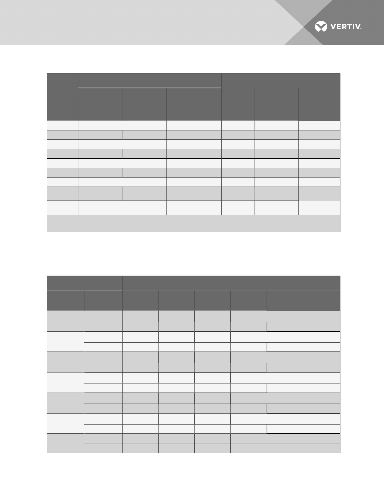
Table 5.6 Refrigerant required, R-410A, approximate
Single Circuit, lb/circuit (kg/circuit) DualC ircuit, lb/circuit (kg/circuit)
Condenser
Models
MCS028 2.5 (1.2) 21.7 (9.8) — — — —
MCS056 — — — 2.5 (1.2) 21.7 (9.8) —
MCM040 3.5 (1.6) 22.7 (10.3) — — — —
MCM080 8.5 (3.8) 39.8 ( 18.1) 17.0 (7.7) 3.5 (1.6) 22.7 (10.3) —
MCM160 — — — 8.5 (3.8) 39.8 (18.1) 17 (7.7) / 24 (10.9)
MCL055 5.0 (2.3) 24.2 (11.0) — — — —
MCL110 10.7 (4 .9) 4 9.1 (22.3) 19.2 (8.7) 5.2 (2.4) 24.4 ( 11.1) 13.7 (6.2)
MCL165 18.4 (8.4) 79.9 ( 36.2)
MCL220 27.0 (12.3) 102.9 (46.7) 42.5 (19.3) 12.3 (5.6) 50.7 (23.0)
1. Small receiver is used with DA050, DA080 and DA085; large receiver is used with DA125, DA1 50 andD A165.
Source: DPN002411 , Rev. 7
Condensers w/o
Liebert Lee-
Temp
Condensers with
Liebert Lee-
Temp
Condensers
withLiebert DSE Small
Receiver/
Larg eReceiver
26.9 (12.2)/
33.9 (15.4)
1
Condensers
w/o
LiebertLee-
Temp
— — —
Condensers
withLiebert Lee-
Temp
Condenserswith
LiebertDSE
Small Receiver/
Larg e Receiver
20.8 (9.4) / 27.8
(12.6)
5.3.1 Recommended Refrigerant Line Sizes
Table 5.7
Recommended Refrigerant Line Sizes, OD Cu
1
System Fluid : R-4 10A Standard and Digital ScrollModels
Model
CR019RA/
CR020RA
CR035RA
PX011
PX018
PX023
PX029
DA050/
DA080/ DA085
Equivalent
Length, in.
Hot Gas Line 3/4 3/4 3/4
LiquidL ine 5/8 5/8 5/8 3/ 4 —
Hot Gas Line 7/8 7/8 7/8
LiquidL ine 3/4 3/4 3/4 7/8 —
Hot Gas Line 1/2
LiquidL ine 3/8 1 /2 1/2 1/2 —
Hot Gas Line 5/8 5/8 5/8
LiquidL ine 1/2 1/2 1 /2 5/8 —
Hot Gas Line 3/4 3/4 3/4
LiquidL ine 5/8 5/8 5/8 5/8 —
Hot Gas Line 7/8 7/8 7/8
LiquidL ine 5/8 5/8 5/8 3/ 4 —
Hot Gas Line 1 -1/8 1-1/ 8 1-1/ 8 1-1 /8 1- 1/8
LiquidL ine 7/8 7/8 7/8 7/8 7/8
50 ft (15m) 100 ft (30m) 150 ft (45m) 300 ft (91m) 450ft (137m)
5/8
1
5/8
1
7/8
1-1/8
5/8
3/4
7/8
1-1/8
1
1
1
1
1
1
—
—
—
—
—
—
Vertiv | Liebert® MC™ Installer/User Guide | 76
Page 77
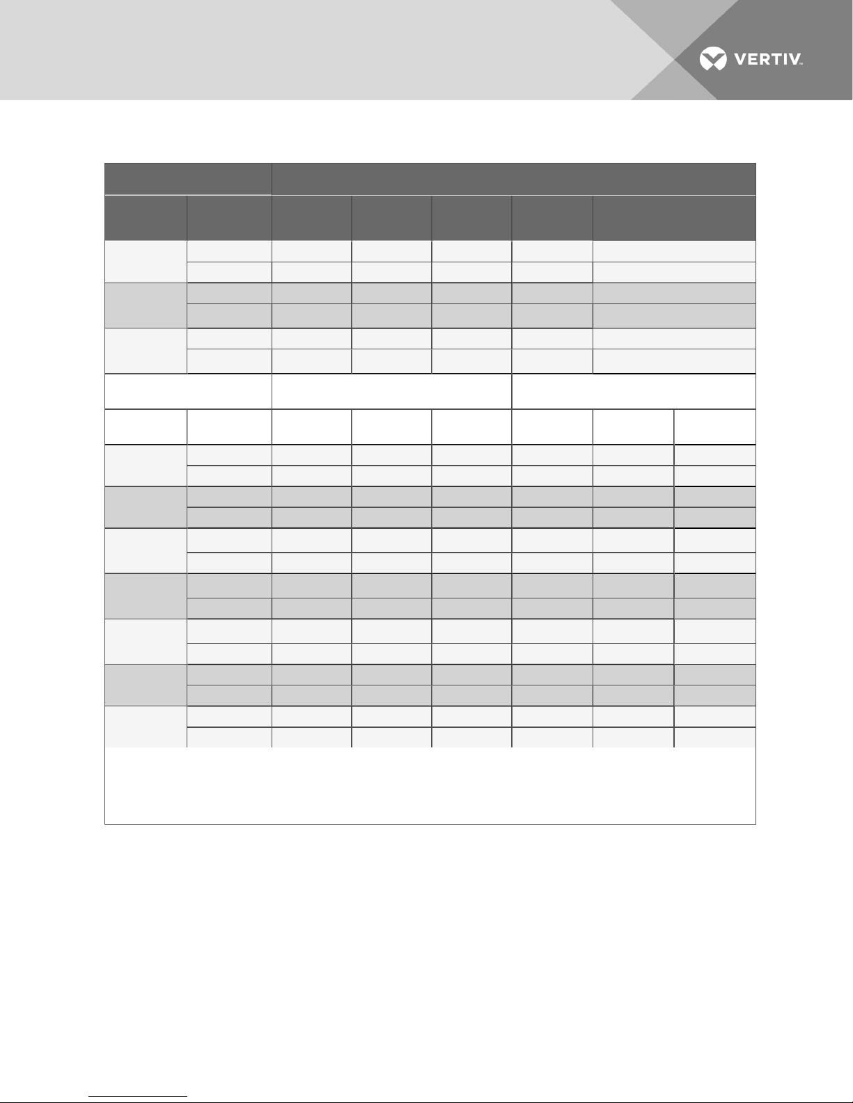
Table 5.7 Recommended Refrigerant Line Sizes, OD Cu (continued)
System Fluid : R-4 10A Standard and Digital ScrollModels
Model
DA1 25
DA1 50
DA1 65
System Fluid : R-407C Standard Scroll Models (Non-Digital Scroll)
Model
DS028
DS035
DS042
DS053
DS070
3
DS077
3
DS1 05
Consult factory for proper line sizingfor R-4 10A DX-only system-piping runs longer than 300 ft. (91.4m), R410A Liebert DSE sys tem piping runs
longer than 4 50ft. (137m) , or R407-C runs longer than 150 ft. (45.7m) equivalentlength.
1. D ownsize vertical riser one trade size (1-1 /8” to 7/8” or 7/8” to 3/4” or 5/8” to 1/2”) .
2. When the ver tical elevationbetween the indoor DA150/165 unitexceeds 25 ft., the liquid-line pipe diameter can be 7/8”.
3. Digital scroll not available on 077 and105 models.
Equivalent
Length, in.
Hot Gas Line 1- 3/8 1-3/8 1- 3/8 1-3/8 1-3/8
LiquidL ine 7/8 7/8 7/8 7/8 7/8
Hot Gas Line 1- 3/8 1-3/8 1- 3/8 1-3/8 1-3/8
LiquidL ine 7/8
Hot Gas Line 1- 3/8 1-3/8 1- 3/8 1-3/8 1-3/8
LiquidL ine 7/8
50 ft (15m) 100 ft (30m) 150 ft (45m) 300 ft (91m) 450ft (137m)
1-1/8
1-1/8
2
2
1-1/8
1-1/8
2
2
1-1/8 1- 1/8
1-1/8 1- 1/8
4-Step Semi-Hermetic
orDigitalScrollModels
Equivalent
Length, in.
Hot Gas Line 7/8 7/8 7/8 3/4 3/ 4 7/8
LiquidL ine 1/2 5/8 5/8 1 /2 5/8 5/8
Hot Gas Line 7/8 7/8 7/8 3/4 7/8 7/8
LiquidL ine 1/2 5/8 5/8 1 /2 5/8 5/8
Hot Gas Line 7/8 7/8 7/8 7/8 7/8
LiquidL ine 1/2 5/8 5/8 5/8 5/8 5/8
Hot Gas Line 7/8 1-1/8 1-1 /8 7/8
LiquidL ine 5/8 7/8 7/8 7/8 7/8 7/ 8
Hot Gas Line 1 -1/8 1-1/ 8 1-1/ 8
LiquidL ine 7/8 7/8 7/8 7/8 7/8 7/8
Hot Gas Line 1 -1/8 1-1/ 8 1-1/ 8 1-1 /8 1 -1/8 1-1/8
LiquidL ine 7/8 7/8 7/8 7/8 7/8 7/8
Hot Gas Line 1- 3/8 1-3/8 1- 3/8 1-3/8 1-3/ 8 1-3/8
LiquidL ine 7/8 7/8 1-1/ 8 7/8 7/8 7/8
50 ft (15m) 100 ft (30m) 150 ft (45m) 50 ft (15m) 100 ft (30m) 150 ft (45m)
1-1/8
1
1-1/8
1-1/8
1
1-1/8
1
1-1/8
1-1/8
1
1
1
Vertiv | Liebert® MC™ Installer/User Guide | 77
Page 78
Table 5.8 Interconnecting piping refrigerant charge for self-contained DX units with remote
condenser
R-407C, lb/100ft. (kg/30m) R- 410A, lb/100ft. (kg/30m)
Line Size O.D., in.
Hot Gas L ine L iquid L ine Hot Gas Line Liquid Line
3/8 — 3.6 (1.6) — 3.2 (1.4)
1/2 0.5 ( 0.2) 6.7 (3.0) 0.7 (0.3) 5.9 (2.7)
5/8 0.8 (0.4) 10.8 ( 4.8) 1.1 (0.5) 9.6( 4.3)
3/4 1.2 (0.5) 16.1 (7.2) 1 .6 ( 0.7) 14.3 (6.4)
7/8 1 .7 (0.8) 22.3 (10.0) 2.3 ( 1.0) 1 9.8 (8.8)
1-1/8 2.9 (1.3) 38.0 ( 17.0) 3.9 (1.7) 33.8 (15.1)
1-3/8 4.4 (2.0) 57.9 (25.9) 5.9 (2.6) 51.5 (23.0)
1-5/8 6.2 (2.8) — 8.4 (3.7) —
1. D ata based on50°F Evap 15°F superheat125°F SCT 10°F subcooling
2. Source: DPN003099, Rev. 0
5.4 Equipment Application Guidelines
Pump-down must be disabled on the indoor unit when using the Liebert MC condenser, due to the
reduced volume in the condenser coil.
Vertiv™ recommends adding a discharge line check valve and crankcase heater when connecting the
Liebert MC condenser to Liebert indoor units built before 2012. The check valve and crankcase heater are
needed for compressor protection. Additional liquid line Schrader ports are required at the indoor unit to
properly charge systems with Liebert MC condensers.
5.5 Refrigerant Oil Addition Procedures
Consult the user manual for the indoor unit to determine whether additional oil is required for each circuit.
Factors such as compressor, condenser type, piping lengths, receiver and total circuit refrigerant charge
influence this requirement.
5.6 System Dehydration/Leak Test
Procedures for leak check and evacuation of the entire refrigeration system are contained in the indoor
unit’s installation manual. Use the proper manual section corresponding to the winter control system used
on the condenser (with or without Liebert Lee-Temp™ or Liebert DSE™ receivers) and the refrigerant to
be charged into the system.
5.7 System Charging with Liebert MC
5.7.1 Liebert MC Charging, Units with Liebert Lee-Temp™Receivers
Consult the indoor unit’s manual for charging systems with Liebert Lee-Temp receivers. These
procedures will be identical to systems with fin/tube condenser coils, but the refrigerant volumes will be
much lower. Consult Table 5.5 on page75 and Table 5.6 on page76 for refrigerant required by a
condenser with Liebert Lee-Temp.
Vertiv | Liebert® MC™ Installer/User Guide | 78
Page 79

5.7.2 Liebert MC Condenser Charging with Liebert DSE™Receivers
Consult the Liebert DSE manual (SL-18925) for charging Liebert DSE systems. All Liebert DSE require
installation of a Liebert DSE receiver on each condenser circuit, with or without a Liebert EconoPhase
pump module installed. Consult Table 5.6 on page76 for condenser and receiver refrigerant
requirements.
5.7.3 Liebert MC Charging, Premium Efficiency Control, Units without Receivers
Source: DPN002411, Rev. 7
Liebert MC condensers are charge-sensitive and require accurate calculation of the system charge to
avoid overcharging. To avoid overcharge, additional guidelines are recommended to ensure trouble-free
operation.
• When charging system in an outdoor ambient below 50°F (10°C), recheck the subcooling
against Table 5.10 on the next page when the ambient temperature is above 60°F (15.6°C)
• The indoor space should be maintained at 70-80°F (21-26.7°C) return air before final charge
adjustments are made.
• Charging a unit at temperatures above 80°F (26.7°C) return air may result in the unit being
overcharged.
• Charge by subcooling measurement at the indoor unit. See Table 5.10 on the next page for
target subcooling temperatures.
• Pressure and temperature measuring instruments should be capable of measuring to ±10 psig
(68.9kPa) and ± 2°F (1.1°C) for best subcooling measurement.
1. Check the nameplate on the indoor unit for refrigerant type to be used. Unit control
configurations differ depending on refrigerant type.
2. Refrigerant charging requires the unit to be in operation. Refer to the indoor unit’s user
manual for the Checklist for Completed Installation.
3. Calculate the amount of charge for the system. Refer to the indoor unit user manual, and
condenser and refrigerant line charge data in the appropriate tables.
4. Weigh in as much of the system charge as possible before starting the unit.
Do not exceed the calculated charge by more than 0.5 lb. (0.23kg).
NOTICE
Risk of improper refrigerant charging. Can cause equipment damage.
Refrigerant R-407C and R-410A are blended refrigerants and must be introduced and charged from the
cylinder only as a liquid.
When adding liquid refrigerant to an operating system, it may be necessary to add the refrigerant
through the compressor suction service valve. Care must be exercised to avoid damage to the
compressor.
Vertiv™ recommends connecting a sight glass between the charging hose and the compressor suction
service valve. This will permit adjusting the cylinder hand valve so that liquid can leave the cylinder while
allowing vapor to enter the compressor.
NOTICE
Risk of refrigerant overcharge. Can cause equipment damage.
Vertiv | Liebert® MC™ Installer/User Guide | 79
Page 80
Do not use the sight glass as an indicator when charging Liebert MC condenser systems.
5. Turn On the Liebert MC disconnect switch.
6. Turn on the indoor unit disconnect switch. Operate the unit for 30 minutes using the charging
function of the indoor-unit control for each circuit of the system. The charging function is in
the diagnostic section of Liebert iCOM® (see Liebert iCOM user manual, SL-18847, available at
www.VertivCo.com.
The charging function operates the compressor(s) at full capacity and energizes the liquid line
solenoid valve(s). The reheat and humidifier are disabled. Manual operation of the indoor fans
from the diagnostic menu of Liebert iCOM is required. A minimum 20psig (138kPa) must be
established and maintained for the compressor to operate. The charging function can be reset
as many times as required to complete unit charging.
Table 5.9 Charge amounts per 100 ft. (30m) of pipe by line size
R-407C (R-22), lb/100 ft. (kg/30m) R-410A, lb/100 ft. (kg/30m)
Line Size O.D., in.
Hot Gas L ine L iquid Line Hot Gas Line L iquid L ine
3/8 — 3.6 (1.6) — 3.2 (1.4 )
1/2 0.5 (0.2) 6.7 (3.0) 0.7 (0.3) 5.9(2.7)
5/8 0.8 (0.4) 10.8 ( 4.8) 1.1 (0.5) 9.6 ( 4.3)
3/4 1.2 (0.5) 16.1 (7.2) 1.6 (0.7) 14.3 (6.4)
7/8 1.7 (0.8) 22.3 (10.0) 2.3 (1.0) 19.8 ( 8.8)
1-1/8 2.9 (1.3) 38.0 ( 17.0) 3.9 (1.7) 33.8 (15.1)
1-3/8 4.4 (2.0) 57.9 ( 25.9) 5.9 (2.6) 51 .5 (23.0)
1-5/8 6.2 (2.8) — 8.4 (3.7) —
Data based on50°F Evap, 15°F superheat, 125°F S CT, 1 0°F subcooling.
Source: DPN002411 , Rev. 7
7. Attach pressure and temperature instruments to the liquid line of the indoor unit. Measure the
initial subcooling and continue to add charge until reaching the recommended subcooling for
the current outdoor ambient temperature (see Table 5.10 below). The outdoor ambient can be
read from the Liebert MC condenser control menu ID F02.
NOTE: To determine subcooling measurement, a liquid line pressure reading (at the factory-installed
Schrader tap) needs to be measured along with obtaining a temperature reading on the liquid line.
Convert the liquid line pressure reading into a temperature by utilizing a Pressure-Temperature Guide
or Table 5.11 on the facing page. The difference between this converted temperature and the actual
temperature will determine the system’s subcooling. For R-407C make sure to use the saturated liquid
temperature to calculate subcooling.
Table 5.10 Target subcooling for ambient outdoor temperature
Ambient Temp °F (C°) Subcooling °F (C°)
0 (-17.8) 22 (12.0)
10 (-12.2) 22 (12.0)
20 (-6.7) 22 (12.0)
30 (-1.1) 22 (12.0)
Vertiv | Liebert® MC™ Installer/User Guide | 80
Page 81
Table 5.10 Target subcooling for ambient outdoor temperature (continued)
Ambient Temp °F (C°) Subcooling °F (C°)
40 (4.4) 22 (12.0)
50 (10.0) 21 ( 11.7)
60 (15.6) 19 (10.8)
70 (21.1 ) 17 (9.3)
80 ( 26.7) 13 (7.2)
90 (32.2) 9 (5.0)
95 (35.0) 7 (3.9)
100 (37.8) 5 (2.9)
105 (40.6) 3 (1.8)
110 (4 3.3) 1 (0.7)
125 (51.7) 0
DPN002411 , Rev. 7
8. As head pressure builds, the variable fan speed controlled condenser fan begins rotating. The
fan will run at full speed when sufficient head pressure is developed.
Table 5.11 Liquid pressures and temperatures
Pressure Psig (Bar) R407C1°F (°C) R410A1°F (°C) R22 °F (°C)
170 (11.7) 81.5 (27.5) 59.8 (15.4) 90.6(32.6)
180 (12.4) 85.1 (29.5) 63.1 (17.3) 94.3 (34 .6)
190 (13.1) 88.6(31.5) 66.3 (19.1) 97.9 (36.6)
200 (13.8) 92.0 (33.3) 69.5 (20.8) 101.4 (38.6)
210 (14 .5) 95.2 (35.1) 72.5 (22.5) 104 .7 (40.4)
220 (15.2) 98.3 ( 36.8) 75.4 (24.1) 108.0 (42.2)
230 (15.9) 101.4 (38.5) 78.2 ( 25.7) 111 .1 (44.0)
240 (16.6) 1 04.3 (4 0.2) 80.9 (27.2) 114.2 (45.7)
250 (17.2) 107.2 (41.8) 83.6(28.7) 117.1 (47.3)
260 (17.9) 109.9 (43.3) 86.2 (30.1) 120.0 (48.9)
270 (18.6) 112.6 (44.8) 88.7 ( 31.5) 122.8 (50.4)
280 ( 19.3) 11 5.3 (46.3) 91.1 (32.8) 125.5 ( 52.0)
290 (20.0) 117.8 (47.7) 93.5 ( 34.2) 1 28.2 (53.4)
300 (20.7) 120.3 (4 9.1) 95.8 (35.5) 130.8 (54.9)
310 (21.4) 122.8 ( 50.4) 98.1 (36.7) 133.3 (56.3)
320 (22.1) 125.2 (51.8) 1 00.3 (38.0) 135.8 ( 57.7)
330 (22.8) 127.5 (53.1) 102.5 (39.2) 1 38.2 (59.0)
340 (23.4) 129.8 (54.3) 104.6 (4 0.3) 1 40.6 (60.3)
350 (24.1) 132.1 (55.6) 106.7 ( 41.5) 142.9 (61.6)
360 (24.8) 134 .3 (56.8) 108.7 (42.6) 1 45.2 (62.9)
370 (25.5) 136.4 (58.0) 110.7 (43.7) 14 7.4 (64.1)
380 ( 26.2) 138.6 (59.2) 112.7 (44.8) 1 49.6 ( 65.4)
Vertiv | Liebert® MC™ Installer/User Guide | 81
Page 82
Table 5.11 Liquid pressures and temperatures (continued)
Pressure Psig (Bar) R407C1°F (°C) R410A1°F (°C) R22 °F (°C)
390 (26.9) 14 0.6 (60.3) 114.5 (45.9) 151.8 (66.5)
400 (27.6) 142.7 (61.5) 116.4 (46.9) 153.9 ( 67.7)
500 (34.5) 161.3 (71.8) 133.5 ( 56.4) 173.1 (78.4)
600 ( 41.4) 177.4 (80.8) 148.1 (64.5) 189.5 ( 87.5)
1. Values are for saturatedliquid.
2. Source: DPN002411, Rev. 7
Vertiv | Liebert® MC™ Installer/User Guide | 82
Page 83

6 CHECKLIST FOR COMPLETED INSTALLATION
6.1 Moving and Placing Equipment
______ 1. Unpack and check received material.
______ 2. Proper clearance for service access has been maintained around the equipment.
______ 3. Equipment is level and mounting fasteners are tight.
6.2 Electrical
_________ 1. Line voltage connected and matches equipment nameplate.
_________ 2. Power line circuit breakers or fuses have proper ratings for equipment installed.
_________
_________
_________ 5. Confirm that unit is properly grounded to an earth ground.
_________ 6. Electrical service conforms to national and local codes.
_________
_________
_________
_________
3. Control wiring connections completed between indoor cooling unit and
condenser.
4. All internal and external high-voltage and low-voltage wiring connections are
tight to the proper torque ratings shown on the components.
7. Monitoring wiring connections completed, when equipped, to indoor cooling unit
or external monitoring panel.
8. Verify that the Premium EC fan condenser is not connected to a delta power
supply.
9. Verify that the CANbus wiring, CANbus “END of Line” jumper position and the
CANbus “Device Address DIP Switch” setting is correct according to the
application at the job site.
10. Verify that Terminals 70, 71 and 230 (when applicable) are used and that they
are properly wired, particularly on systems that use two condensers for one
indoor unit.
6.3 Piping
_________ 1. Piping is completed to corresponding indoor cooling unit refrigeration circuit.
_________ 2. Piping is leak-checked, evacuated and charged with specified refrigerant.
_________ 3. Additional refrigerant oil added, if required, per circuit.
_________ 4. Piping is properly sized, sloped and trapped for proper oil return.
_________ 5. Piping is routed to reduce potential of rub-through or chaffing.
_________
Vertiv | Liebert® MC™ Installer/User Guide | 83
6. Hot gas line on Liebert Lee-Temp™ is fastened to the side of the cabinet and
isolated for vibration reduction.
Page 84

6.4 Other
_________
_________
_________
1. Foreign material removed from in and around all equipment installed
(construction materials, construction debris, etc.).
2. Installation materials and tools have been removed from in and around all
equipment (literature, shipping materials, tools, etc.).
3. Blank startup sheet located, ready for completion by installer or start-up
technician.
Vertiv | Liebert® MC™ Installer/User Guide | 84
Page 85
7 INITIAL STARTUP CHECKS AND COMMISSIONING
WARNING! Arc flash and electric shock hazard. Open all local and remote electric power
disconnect switches, verify with a voltmeter that power is Off and wear personal protective
equipment per NFPA 70E before working within the electric control enclosure. Failure to
comply can cause serious injury or death.
Customer must provide earth ground to unit, per NEC, CEC and local codes, as applicable.
Before proceeding with installation, read all instructions, verify that all the parts are included
and check the nameplate to be sure the voltage matches available utility power.
The LiebertiCOM® microprocessor does not isolate power from the unit, even in the “Unit Off”
mode. Some internal components require and receive power even during the “Unit Off” mode of
LiebertiCOM control.
The factory-supplied disconnect switch is inside the unit. The line side of this switch contains
live high-voltage.
The only way to ensure that there is NO voltage inside the unit is to install and open a remote
disconnect switch. Refer to unit electrical schematic.
Follow all local codes.
WARNING! Risk of electric shock. Can cause injury or death.
Open all local and remote unit electric power supply disconnect switches, wait 10 minutes and
verify with a voltmeter that power is Off before working within the fan speed control, the EC fan
electrical enclosures or checking any electrical connections or functions. Unit contains
potentially lethal electrical voltage. Line side of factory disconnect remains energized when
disconnect is Off.
Only properly trained and qualified personnel may perform repair, maintenance and cleaning
operation.
WARNING! Risk of high-speed, rotating fan blades. Can cause injury or death.
Fan blades can start rotating without warning at any time during a cooling cycle or after power
is restored after a power failure. Open all local and remote unit electrical power supply
disconnect switches, verify with a voltmeter that the power is Off and verify that all fan blades
have stopped rotating before working on or near the fans.
Vertiv | Liebert® MC™ Installer/User Guide | 85
Page 86

7.1 Startup Checklist
Refer to Checklist for Completed Installation on page83 and verify that all installation items have been
completed before beginning to start the condenser.
7.2 Initial Startup
1. Locate Liebert MC Condensers Warranty Inspection Check Sheet, Document # PSWI-8542408CO.
2. Turn the condenser disconnect On.
3. Turn the indoor unit ON and set for cooling to allow operation of condenser.
4. Check the fans for proper rotation: Counterclockwise when viewing the unit from the fan guard
(top) side.
5. Check that air is being drawn through the coil and discharged out the fan assembly.
6. Complete Liebert MC Condensers Warranty Inspection Check Sheet, Document#PSWI-8542408CO.
NOTE: This document must be completed and forwarded to your local Vertiv™ sales office to validate
warranty.
• Contact your local Vertiv™ sales representative or Vertiv™ Liebert Services support about any
questions or problems during unit startup and commissioning.
Local Vertiv™ sales offices and Liebert Thermal Management support contacts can be found
at www.VertivCo.com or by calling 1-800-543-2378.
Vertiv | Liebert® MC™ Installer/User Guide | 86
Page 87
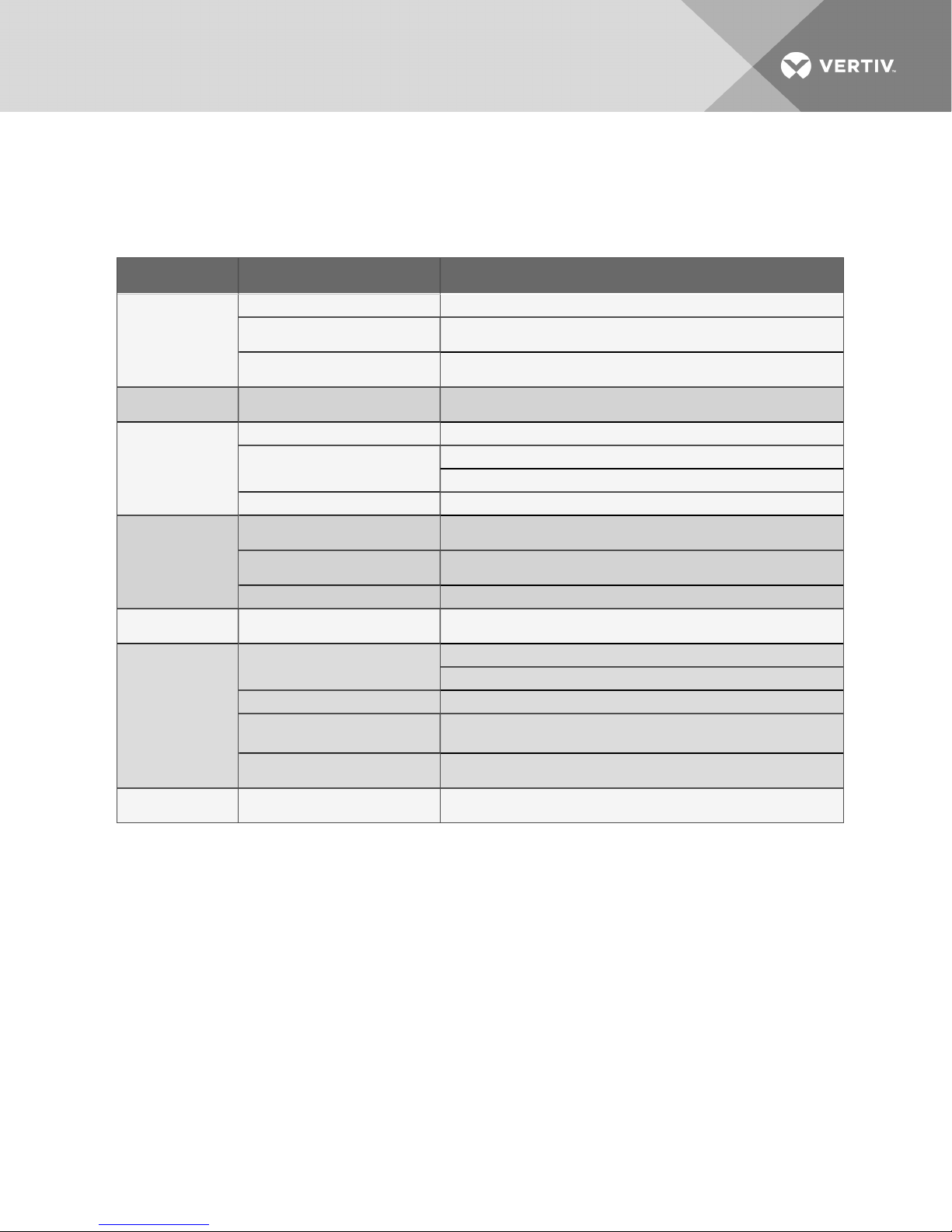
8 TROUBLESHOOTING
Table 8.1
Troubleshooting
Symptom Possible C ause Check or Remedy
No power to condenser. Check voltage at input terminal block.
Condenser willnot
start
Low discharge
pressure
Highdischarge
pressure
SPD green andr ed
LED s are
extinguished
SPD red LE D is
illuminated
Control Board LEDs
do not light.
Fan will not run
Circuitbreaker or fuse for low-voltage
transformer in condenser is tripped.
No low-voltage signal to/from indoor
unit.
Faulty head pressure control valve or
premium efficiency control board.
Dirty condenser fins. Cleancoil.
Condenser fans not operating.
Highr efrigerant charge Check refrigerant charge.
No voltage or improper phasingexists
at condenser.
Electrical connections to SPD ar e
faulty.
Condenser disconnect is turnedOff. Recheck lights with disconnect switch in the On position.
A surge exceeding the rating of the
SPD has occurred.
Connection to P24 is loose or
disconnected.
Fuse located next to P24 has blown. Verify that the fuses next to P24 have not blown. Replace as needed.
24V transformer has failed.
Premium Efficiency Control Board has
failed.
Jumper not installedbetween 24 V and
DIN1 (for Ziehl-Abeggfan motor).
Locate problem in condenser electrical panel and repair.
Locate open circuitandrepair.
Replace if defective.
Check for low-voltage s ignal from indoor unit.
Check fan motors and fuses .
Check voltage atinput terminal block.
Locate connection problem andrepair.
Replace SPD andinspectother components for damage and replace them if
necessar y.
Check the connection to P24 to verify that is connected s ecurely.
Check the connector from the transformer for loose terminals.
With a voltmeter verify that the output from the transformer is 24Vac ±10%. If the
value exceeds ±10%, verify that the correct primary leads are being used.
If there is no output voltage, verify that the primar y connections are secure and
receiving the corr ect voltage. If they are, replace the transformer.
Install jumper between 24 V and DIN1 (for Ziehl A beggfan motor).
Vertiv | Liebert® MC™ Installer/User Guide | 87
Page 88

This page intentionally left blank.
Vertiv | Liebert® MC™ Installer/User Guide | 88
Page 89

9 CONTROL OPERATION
The Liebert MC Premium Efficiency Control takes approximately 30 seconds to boot up once power is
applied to the condenser. The LED on the Premium Efficiency Control Board reads “888” while the board
is booting up. Once the control has booted up, the display shows “F00” and then the value for F00. With
the control operational, the condenser fan(s) turn in less than 5 seconds after receiving a signal from the
indoor unit that the compressor(s) are On. Consider using UPS equipment on both data center cooling
units and Liebert MC condensers to maintain uninterrupted cooling capability.
For the first 60 seconds of operation after the compressor turns on, the condenser fan(s) will run at a fixed
speed, set at the factory, based on ambient temperature: faster at higher temperatures, slower at lower
temperatures. After 60 seconds, the control adjusts the fan speed based on the liquid pressure
transducer. If the liquid pressure transducer fails, the condenser uses temperature sensors to control the
fan speed based on the liquid line temperature. The condenser fans continue to operate for
approximately 30 seconds after compressors turn Off.
The Liebert MC fans have various alarm conditions, such as loss of voltage and loss of control signal, that
will stop the condenser fans. Once the alarm condition is no longer present the Liebert MC fans will turn
on automatically if compressors are On.
9.1 Premium Efficiency Control Board and Interface
The Liebert MC Premium Efficiency Control board has a stacked board arrangement. There are three
seven-segment LED’s and four keys as human machine interface (see Figure 9.2 on page91).
NOTE: Indicator lights should be On to indicate signal is present. See Figure 9.1 on the next page, #1, 2
and 3.
Vertiv | Liebert® MC™ Installer/User Guide | 89
Page 90
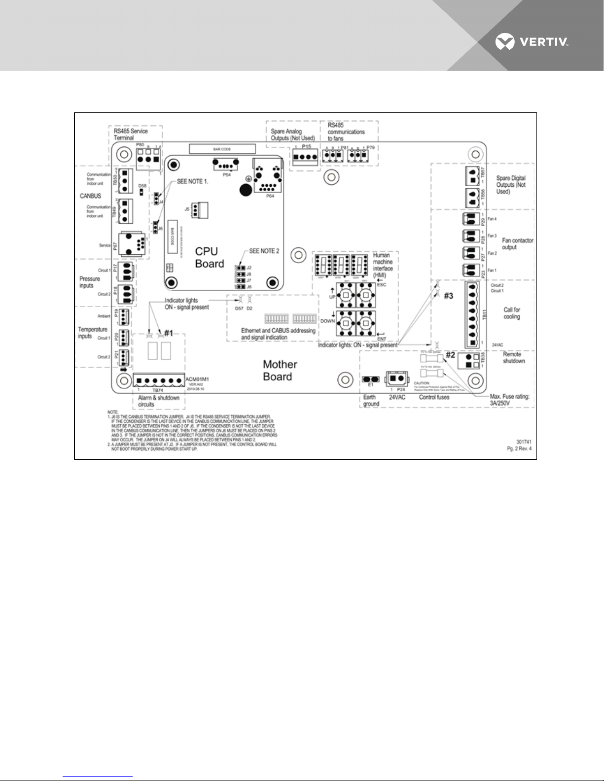
Figure 9.1 Premium efficiency fan control board
Vertiv | Liebert® MC™ Installer/User Guide | 90
Page 91
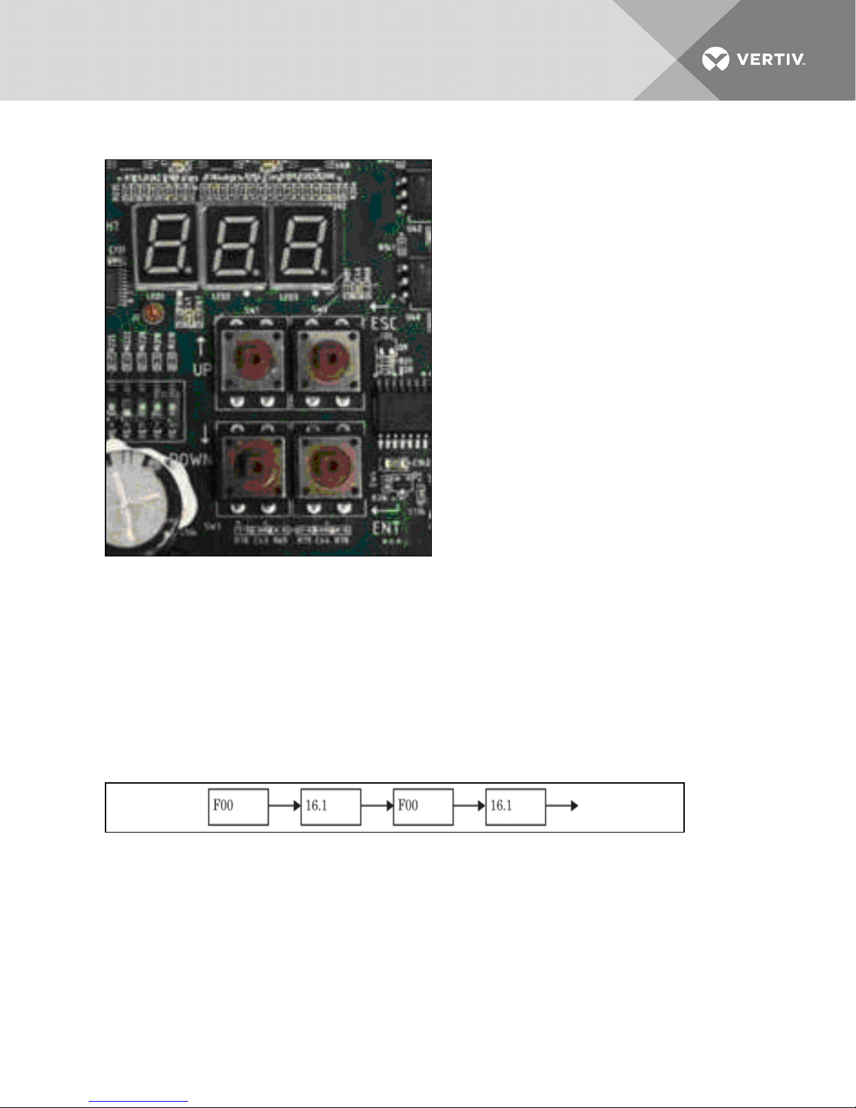
Figure 9.2 Premium Efficiency Control Interface - Human Machine Interface (HMI)
The Premium Efficiency Controls are factory-configured for refrigerant type and whether the condenser
was sold with or without a Liebert Lee-Temp™ or Liebert DSE system. No field-configuration is necessary
for proper and efficient condenser operation.
9.1.1 Initial Screen Upon Power-On
The controller displays the initial screen after it is powered On. The initial screen shows the first item of
analog signals menu. The F00 and value of condenser pressure 1 are displayed alternatively and F00
means the item ID of condenser pressure 1. The display sequence is shown Figure 9.3 below. In the figure,
16.1 is an example and the value is dependent on the sampling result.
Figure 9.3 Initial controller display
9.1.2 Main Menu Description
In initial screen, presses ESC key, the LED enters the first menu of the main menu. The main menu
includes four menus:
• Analog Signals Menu
• Active Alarms Menu
• History Alarms Menu
• Configuration Menu
Vertiv | Liebert® MC™ Installer/User Guide | 91
Page 92
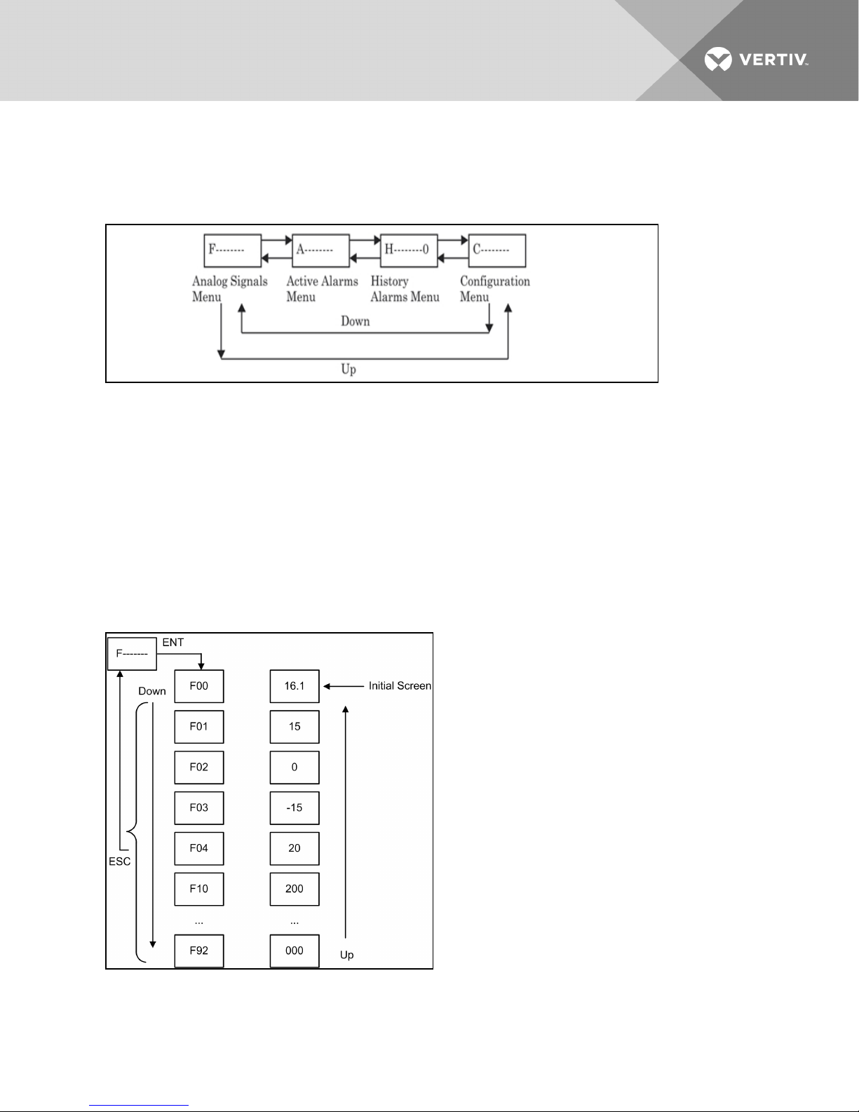
In the Main Menu, press Up and Down keys to switch to different menus, and press the ENT key to enter
the sub menus of the current menu. The operation and structure of main menu are shown in the following
figure.
Figure 9.4 Main Menu operation and structure
Notice
Risk of improperly altered configuration menu settings. Can compromise equipment operation.
Changing the configuration menu settings can cause unanticipated results. These settings should be
changed only by properly trained and qualified personnel or as directed by the factory.
9.1.3 Analog Signals Menu Description
In analog signals menu F-----------, press the ENT key to enter its items. The information of analog signal
items includes condenser pressure, temperature and EC Fan actual speed. The display mode is that the
item ID and signal value are displayed alternatively. The operation and item structure of analog signals
menu are shown in Figure 9.5 below. Table 9.1 on the facing page defines the signals.
Figure 9.5 Analog Signals Menu
Vertiv | Liebert® MC™ Installer/User Guide | 92
Page 93
Table 9.1
Analog signal definitions
Units (C90)
Item ID Meaning
Imperial Metric
F00 Condenser press ure 1 psi bar
F01 Condenser pressure 2 psi bar
F02 Ambienttemperature °F °C
F03 Refrigerant temperature 1 °F °C
F04 Refrigeranttemperature 2 °F °C
F10 EC Fan1 actualspeed RPM RPM
F11 EC Fan1 requestedspeed % %
F12 EC Fan 1 power kW kW
F13 EC Fan 1 firmware version Hex format Hex format
F20 EC Fan2 actual speed RPM RPM
F21 EC Fan 2 requesteds peed % %
F22 E C Fan 2 power kW kW
F23 E C Fan 2 firmware version Hex format Hex format
F30 EC Fan 3 actual speed RPM RPM
F31 EC Fan 3 requesteds peed % %
F32 E C Fan 3 power kW kW
F33 E C Fan 3 firmware version Hex format Hex format
F40 E C Fan 4 actual s peed RPM RPM
F41 EC Fan 4 requested speed % %
F42 EC Fan 4 power kW kW
F43 EC Fan 4 firmware version Hex format Hex format
F50 Subcooling1 °F °C
F51 S ubcooling2 °F °C
F90 Firmware Version Major
F91 Firmwar e Version Minor —
F92 Firmwar e Version Build —
Source: 303847P1 Rev. 4
1.02.004
9.2 Premium Efficiency Condenser Alarm Codes
The following procedure and chart details the alarm codes that may be displayed from the Active and
History Alarm registers.
Vertiv | Liebert® MC™ Installer/User Guide | 93
Page 94
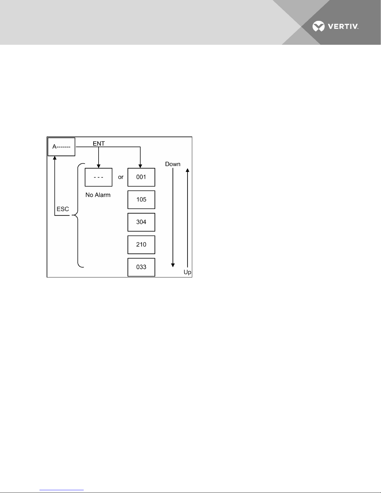
9.2.1 Active Alarms Menu Description
In active alarms menu “A——,” press the ENT key to enter its items. The active alarm item displays all the
active alarms of condenser. When there is an active alarm, the alarm information ID will be directly
displayed. When there is no alarm, “---” is displayed. When there are multiple alarms, the alarm information
IDs will be displayed according to the time sequence (the most-recent alarm will be displayed first). The
operation and items structure of active alarms menu are shown in the following figure. The meanings of
alarm information ID are found in Table 9.2 on the facing page and Table 9.3 on page96.
Figure 9.6 Active alarms menu
9.2.2 History Alarms Menu Description
In history alarms menu “H——―”, press ENT key to enter its items. The history alarm items display 100
history alarm records of the condenser. The item ID is for the sequence number of the history alarms. The
display mode is that the item ID and alarm information ID are displayed alternatively. When there is no
alarm, “---” is displayed. Alarm history can be cleared using the C98 configuration menu item. The
operation and items structure of history alarms menu are shown in the following figure. The meanings of
alarm information ID are given in Table 9.2 on the facing page and Table 9.3 on page96.
Vertiv | Liebert® MC™ Installer/User Guide | 94
Page 95
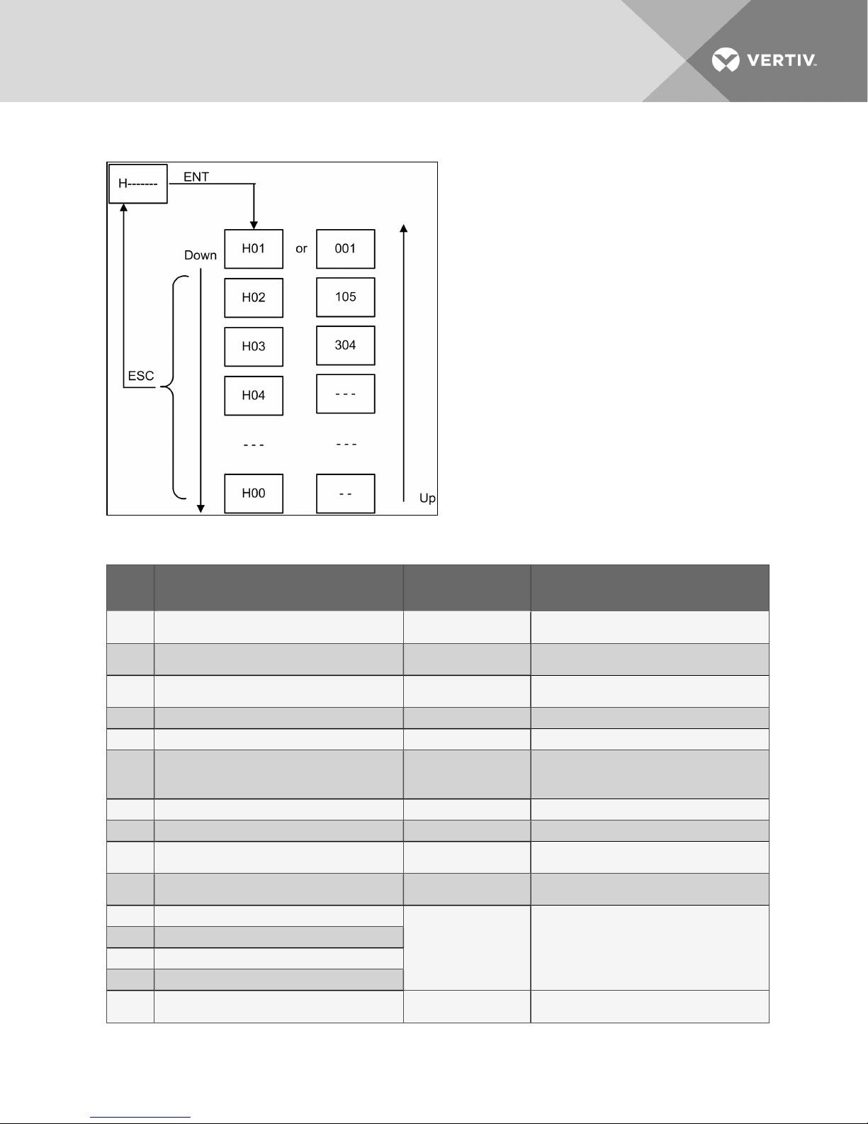
Figure 9.7 History alarms menu
Table 9.2 System alarm information
Alarm
ID
000 CAN communication failure
001 Ethernet communication failure
002 US B communication failure
003 Data corr uption Memory chipis damaged Replace PCB board
004 System error Internalerror Reboot. If r ebootfails, consult factory.
005 Remote s hutdown
006 Shutdown due to EC Fan alar m All fans have failed Consultfactory
007 SPD alarm SPD damaged Replace SPD
008 Condenser pressure Sensor 2 failure
009 Condenser pressure S ensor 2 failure
010 Condenser pressure 1 high alarm
011 Condenser pressure 2 high alarm
012 Condenser pressure 1 low alarm
013 Condenser pressure 2 low alarm
014
Meaning Possible Cause Handling Method
EC Fans peed mode maximum must be overridden due
to condenser pressure 1 high
Communication circuit
missing or damaged
Ethernet hardware or
connection failure
USB device or file is
damaged.
1. Remote shutdown signal
is available
2. TB38 is notconnected
Condenser pressure
Sensor 1 damaged
Condenser pressure
Sensor 2 damaged
Highpres sure: Fanfailure,
clogged coils.
Low pressure: Loss of
charge
Condenser pressure 1
high
Check communication circuit. Ignore alarm on
condensers withoutCAN connections
Ignore alarm, Ethernetconnectionis notpres ent
Replace US B device or file.
For Cause 1, check the r emote s hutdown signal.
For Cause 2, connect TB38.
Replace condenser pressure Sensor 1
Replace condenser pressure Sensor 2
High-press ure alarms: Fix fan and clean coil.
Low-pressure alarms: Check for refrigerant leak.
No action is needed.
Vertiv | Liebert® MC™ Installer/User Guide | 95
Page 96
Table 9.2 System alarm information (continued)
Alarm
ID
015
016 Ambient temperature sensor failure
017 Ambienttemperature high alarm Ambient temperature high No action is needed.
018 Ambient temperature low alarm Ambient temperature low No action is needed.
019 Condenser temperature Sensor 2 failure
020 Condenser temperature S ensor 2 failure
021 Condenser temperature 1 high alarm
022 Condenser temperature 2 high alar m
023 Condenser temperature 1 low alarm
024 Condenser temperature 2 low alarm
025
026
Meaning Possible Cause Handling Method
EC Fans peed mode maximum must be overridden due
to condenser pressure 2 high
EC Fans peed mode maximum must be overridden due
to refrigeranttemperature 1 high
EC Fans peed mode maximum must be overridden due
to refrigeranttemperature 2 high
Condenser pressure 2
high
Ambienttemperature
sensor damaged
Condenser temperature
Sensor 2 damaged
Condenser temperature
Sensor 2 damaged
Hightemperature: Fan
failure, clogged coils.
Low temperature: Consult
factory
Refrigerant temperature 1
high
Refrigerant temperature 2
high
No action is needed.
Replace ambienttemperature sensor
Replace condenser temperature Sensor 1
Replace condenser temperature Sensor 2
High-temperature alarms: Fix fanand clean coils.
Low-temperature alarms: consult factory.
No action is needed.
No action is needed.
Table 9.3 EC Fan alarm information
Alarm
ID
(1-4)
00
(1-4) 01 EC Fan drive error EC Fan is damaged. Replace EC Fan
(1-4) 02
(1-4) 03
(1-4)
04
(1-4) 05 EC Fan IGBT failure EC Fan is damaged. Replace EC Fan
(1-4) 06 EC Fan line fault Power supply abnormal Check power supply
(1-4) 07 EC Fan motor locked Motor is locked Check if EC Fan is locked.
(1-4) 08
(1-4) 09 EC Fan phase failure alarm Phase failure Check power supply
Meaning Possible Cause Handling Method
EC Fanhigh link curr ent
EC Fanearth to ground
fault
EC Fanelectronics heat
sink thermal overload
EC FanHall failure EC Fan is damaged. Replace EC Fan
EC Fanmotor thermal
overload
1. EC Fan is locked.
2. EC Fan is damaged.
EC Fanis damaged. Replace EC Fan
1. EC Fan is locked.
2. EC Fan is damaged.
3. Ambient temperature is too
high
1. EC Fan is locked.
2. EC Fan is damaged.
3. Ambient temperature is too
high
For cause 1 , check if EC Fan is locked.
For cause 2, replace EC Fan
For cause 1 , check if EC Fan is locked.
For cause 2, replace EC Fan
For cause 3, check ambient temperature.
For cause 1 , check if EC Fan is locked.
For cause 2, replace EC Fan
For cause 3, check ambient temperature.
Vertiv | Liebert® MC™ Installer/User Guide | 96
Page 97
Table 9.3 EC Fan alarm information (continued)
Alarm
ID
(1-4) 10
(1-4) 11
(1-4) 12
(1-4) 13 EC Fan high link voltage
(1-4) 14 EC Fan low link voltage
(1-4) 15
Meaning Possible Cause Handling Method
EC Fan-specific
uncategorized alarm
detected
EC Fan-specific
uncategorized war ning
detected
EC Fanelectronics hightemperature condition.
EC Fan4 85 communication
failure
Internal EC Fan issue
1. EC Fan is locked.
2. EC Fan is damaged.
3. Ambient temperature is too
high
1. EC Fan input power supply
high voltage
2. EC Fan is damaged.
1. EC Fan input power supply
low voltage
2. EC Fan detection error
1. Communication between EC
Fan and PCB board failure
2. EC Fan 485 communication
failure
3. Board has problems
4. EC fannotreceiving power
Re-bootcondenser if fans not running. If alarm persists and fans not
running, replace fan.
For cause 1 , check if EC Fan is locked.
For cause 2, replace EC Fan
For cause 3, check ambient temperature.
For cause 1 , measure power supply voltage andcheck if the voltage is
normal
For cause 2, replace EC Fan
For cause 1 , check EC Fan communication circuit
For cause 2, replace EC Fan
For cause 3, replace PCB board
For cause 4 , check fan model is not set for “0”, check that the contactor
for the particular fan is energized, and check fan fuses.
NOTE: (1-4) means the EC Fan addresses. For example, (1-4) 00 means 100 for EC Fan1, and means 200
for EC Fan2, and means 300 for EC Fan3, and means 400 for EC Fan4.
Vertiv | Liebert® MC™ Installer/User Guide | 97
Page 98

This page intentionally left blank.
Vertiv | Liebert® MC™ Installer/User Guide | 98
Page 99

10 LIEBERT SEISMIC APPLICATION—
OPTIONALUNITCONFIGURATION
10.1 Seismic Anchoring Considerations
• Mounting requirement details such as anchor brand, type, embedment depth, edge spacing,
anchor-to-anchor spacing, concrete strength, special instruction and attachment to nonbuilding structures must be outlined and approved by the engineer of record for the project or
building. Structural floors and housekeeping pads must also be seismically designed and
approved by the project or building structural engineer of record to withstand the seismic
anchor loads defined in Table 10.1 on the next page. The installing contractor is responsible
for the proper installation of all anchors and mounting hardware, observing the mounting
requirements detailed in the seismic installation drawings as outlined by the engineer of
record.
• All braces and fasteners are required to maintain IBC/OSHPD certification of conformity.
• Use a washer, lock washer and screw to connect the brace to the bottom beam of the
condenser. (See Figure 10.2 on page102.)
• Use a washer, lock washer and screw to connect the brace to the condenser leg. (See Figure 10.2
on page102)
• Place anchorage plate inside each condenser foot of 18-in. legs prior to fastening to the
structure. MC condensers with 36-in., 48-in. or 60-in. legs do not require separate anchorage
plates for the legs. Use a flat washer, lock washer and nut to connect the condenser to the
customer-supplied anchor on the solid surface (reference Detail A in Figure 10.1 on the next
page). As a minimum, 3/8” grade anchors with American National Standard Series W, Type A,
plain washers (ANSI B18.22.1-1965, R1975) selected to match the nominal anchor diameter must
be installed at each anchor location between the anchor head and equipment for tension load
distribution.
Vertiv | Liebert® MC™ Installer/User Guide | 99
Page 100
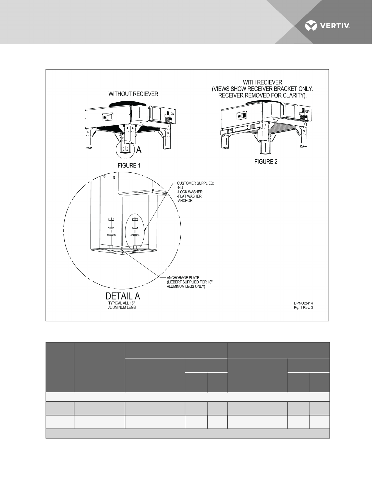
Figure 10.1 Seismic anchorage data for one-fan models
Table 10.1 Seismic anchorage loads for one-fan models
Models
MCS028
Without
Receiver
With
Receiver
MCM040
Vertiv | Liebert® MC™ Installer/User Guide | 100
Figure # in Figure 1 0.1
above
Figure 1 37 14 14 47 24 21
Figure 2 43 15 23 56 27 35
Importance Factor Iρ= 1.0 I mportance Factor Iρ= 1.5
Maximum Anchor
Maximum Compressive
Reaction lb
TensilelbShear
lb
Maximum Compressive
Reaction lb
Maximum Anchor
TensilelbShear
lb
 Loading...