

Page 1

Liebert®
MBSM™ Multiple Bus Synchronization Module
User Manual — Liebert EXL S1 and Liebert NX 225-600kVA
Page 2

The information contained in this document is subject to change
without notice and may not be suitable for all applications. While
every precaution has been taken to ensure the accuracy and
completeness of this document, Vertiv assumes no responsibility
and disclaims all liability for damages resulting from use of this
information or for any errors or omissions. Refer to other local
practices or building codes as applicable for the correct methods,
tools, and materials to be used in performing procedures not
specifically described in this document.
The products covered by this instruction manual are manufactured
and/or sold by Vertiv This document is the property of Vertiv and
contains confidential and proprietary information owned by Vertiv.
Any copying, use or disclosure of it without the written permission of
Vertiv is strictly prohibited.
Names of companies and products are trademarks or registered
trademarks of the respective companies. Any questions regarding
usage of trademark names should be directed to the original
manufacturer.
Technical Support Site
If you encounter any installation or operational issues with your product, check the pertinent
section of this manual to see if the issue can be resolved by following outlined procedures.
Visit https://www.VertivCo.com/en-us/support/ for additional assistance.
Page 3

TABLE OF CONTENTS
CONTACTING VERTIV FOR SUPPORT . . . . . . . . . . . . . . . . . . . . . . . INSIDE FRONT COVER
1.0 INTRODUCTION. . . . . . . . . . . . . . . . . . . . . . . . . . . . . . . . . . . . . . . . . . . . . . . . . . . . . . . 4
1.1 Concepts, Basic Architecture . . . . . . . . . . . . . . . . . . . . . . . . . . . . . . . . . . . . . . . . . . . . . . . . . . . . . . . . . . . . 4
2.0 INSTALLATION. . . . . . . . . . . . . . . . . . . . . . . . . . . . . . . . . . . . . . . . . . . . . . . . . . . . . . . . 5
2.1 Unpacking . . . . . . . . . . . . . . . . . . . . . . . . . . . . . . . . . . . . . . . . . . . . . . . . . . . . . . . . . . . . . . . . . . . . . . . . . . . . . . . 5
2.2 Transporting Without Packaging Materials. . . . . . . . . . . . . . . . . . . . . . . . . . . . . . . . . . . . . . . . . . . . . . 5
2.3 Equipment Delivery and Storage . . . . . . . . . . . . . . . . . . . . . . . . . . . . . . . . . . . . . . . . . . . . . . . . . . . . . . . . 5
2.4 Storage . . . . . . . . . . . . . . . . . . . . . . . . . . . . . . . . . . . . . . . . . . . . . . . . . . . . . . . . . . . . . . . . . . . . . . . . . . . . . . . . . . 6
2.5 Configuration for 60Hz 480V AC Applications . . . . . . . . . . . . . . . . . . . . . . . . . . . . . . . . . . . . . . . . . . 6
2.5.1 Power and Sensing . . . . . . . . . . . . . . . . . . . . . . . . . . . . . . . . . . . . . . . . . . . . . . . . . . . . . . . . . . . . . . . . . . . . . . . 6
2.5.2 Selecting an Installation Site . . . . . . . . . . . . . . . . . . . . . . . . . . . . . . . . . . . . . . . . . . . . . . . . . . . . . . . . . . . . . 6
2.6 Mount the Liebert MBSM on a Wall . . . . . . . . . . . . . . . . . . . . . . . . . . . . . . . . . . . . . . . . . . . . . . . . . . . . . . 7
2.6.1 Transformer Box Connections. . . . . . . . . . . . . . . . . . . . . . . . . . . . . . . . . . . . . . . . . . . . . . . . . . . . . . . . . . . . 8
2.7 Dual Bus UPS Systems. . . . . . . . . . . . . . . . . . . . . . . . . . . . . . . . . . . . . . . . . . . . . . . . . . . . . . . . . . . . . . . . . . 10
2.7.1 Normal Operating Condition . . . . . . . . . . . . . . . . . . . . . . . . . . . . . . . . . . . . . . . . . . . . . . . . . . . . . . . . . . . . .11
2.8 Phase Error Control . . . . . . . . . . . . . . . . . . . . . . . . . . . . . . . . . . . . . . . . . . . . . . . . . . . . . . . . . . . . . . . . . . . . . 11
2.8.1 Liebert MBSM Activation on Bus A . . . . . . . . . . . . . . . . . . . . . . . . . . . . . . . . . . . . . . . . . . . . . . . . . . . . . . 12
2.8.2 Liebert MBSM activation on Bus B . . . . . . . . . . . . . . . . . . . . . . . . . . . . . . . . . . . . . . . . . . . . . . . . . . . . . . 12
2.9 Generator Operation. . . . . . . . . . . . . . . . . . . . . . . . . . . . . . . . . . . . . . . . . . . . . . . . . . . . . . . . . . . . . . . . . . . . 13
2.9.1 Bus A Failure . . . . . . . . . . . . . . . . . . . . . . . . . . . . . . . . . . . . . . . . . . . . . . . . . . . . . . . . . . . . . . . . . . . . . . . . . . . . 13
2.9.2 Bus B Failure. . . . . . . . . . . . . . . . . . . . . . . . . . . . . . . . . . . . . . . . . . . . . . . . . . . . . . . . . . . . . . . . . . . . . . . . . . . . . 13
2.9.3 Both Power Bus Failure . . . . . . . . . . . . . . . . . . . . . . . . . . . . . . . . . . . . . . . . . . . . . . . . . . . . . . . . . . . . . . . . . . 13
2.9.4 Remote Commands . . . . . . . . . . . . . . . . . . . . . . . . . . . . . . . . . . . . . . . . . . . . . . . . . . . . . . . . . . . . . . . . . . . . . 14
2.10 Application Limits . . . . . . . . . . . . . . . . . . . . . . . . . . . . . . . . . . . . . . . . . . . . . . . . . . . . . . . . . . . . . . . . . . . . . . 14
2.10.1 Special Solution, if Required. . . . . . . . . . . . . . . . . . . . . . . . . . . . . . . . . . . . . . . . . . . . . . . . . . . . . . . . . . . . . 16
2.11 Selecting the Priority . . . . . . . . . . . . . . . . . . . . . . . . . . . . . . . . . . . . . . . . . . . . . . . . . . . . . . . . . . . . . . . . . . . 16
2.12 Remote Commands . . . . . . . . . . . . . . . . . . . . . . . . . . . . . . . . . . . . . . . . . . . . . . . . . . . . . . . . . . . . . . . . . . . . . 17
2.12.1 Excluding Bus A . . . . . . . . . . . . . . . . . . . . . . . . . . . . . . . . . . . . . . . . . . . . . . . . . . . . . . . . . . . . . . . . . . . . . . . . . 17
2.12.2 Excluding Bus B . . . . . . . . . . . . . . . . . . . . . . . . . . . . . . . . . . . . . . . . . . . . . . . . . . . . . . . . . . . . . . . . . . . . . . . . . 17
2.12.3 Excluding Bus A and B. . . . . . . . . . . . . . . . . . . . . . . . . . . . . . . . . . . . . . . . . . . . . . . . . . . . . . . . . . . . . . . . . . . 17
3.0 INSTALLATION. . . . . . . . . . . . . . . . . . . . . . . . . . . . . . . . . . . . . . . . . . . . . . . . . . . . . . . 18
3.1 Liebert MBSM Internal Layout . . . . . . . . . . . . . . . . . . . . . . . . . . . . . . . . . . . . . . . . . . . . . . . . . . . . . . . . . . 18
4.0 UPS SETUP. . . . . . . . . . . . . . . . . . . . . . . . . . . . . . . . . . . . . . . . . . . . . . . . . . . . . . . . . . 20
4.1 Liebert MBSM Function Activation . . . . . . . . . . . . . . . . . . . . . . . . . . . . . . . . . . . . . . . . . . . . . . . . . . . . .20
4.2 Liebert MBSM Interconnections . . . . . . . . . . . . . . . . . . . . . . . . . . . . . . . . . . . . . . . . . . . . . . . . . . . . . . . .20
4.3 Power Interconnections . . . . . . . . . . . . . . . . . . . . . . . . . . . . . . . . . . . . . . . . . . . . . . . . . . . . . . . . . . . . . . . . 21
4.4 Signal Interconnections. . . . . . . . . . . . . . . . . . . . . . . . . . . . . . . . . . . . . . . . . . . . . . . . . . . . . . . . . . . . . . . . .22
4.5 Remote Contacts . . . . . . . . . . . . . . . . . . . . . . . . . . . . . . . . . . . . . . . . . . . . . . . . . . . . . . . . . . . . . . . . . . . . . . . 22
Vertiv™|Liebert® MBSM™ User Manual | i
Page 4

FIGURES
Figure 1 Block diagram of a UPS system with Liebert MBSM . . . . . . . . . . . . . . . . . . . . . . . . . . . . . . . . . 4
Figure 2 Moving the Liebert MBSM . . . . . . . . . . . . . . . . . . . . . . . . . . . . . . . . . . . . . . . . . . . . . . . . . . . . . . . . . . . 6
Figure 3 Dimensions, drilling diagram . . . . . . . . . . . . . . . . . . . . . . . . . . . . . . . . . . . . . . . . . . . . . . . . . . . . . . . . . 7
Figure 4 Connection example—Liebert MBSM, Liebert EXL S1 and transformer box . . . . . . . . . 8
Figure 5 Connection example—Liebert MBSM, Liebert NX and transformer box . . . . . . . . . . . . . 9
Figure 6 Dual-bus UPS systems . . . . . . . . . . . . . . . . . . . . . . . . . . . . . . . . . . . . . . . . . . . . . . . . . . . . . . . . . . . . . . 10
Figure 7 Synchronization Components for Dual Bus System. . . . . . . . . . . . . . . . . . . . . . . . . . . . . . . . . 11
Figure 8 Synchronizing to Bus A for Dual Bus System. . . . . . . . . . . . . . . . . . . . . . . . . . . . . . . . . . . . . . . . 12
Figure 9 Synchronizing to Bus B for Dual Bus System. . . . . . . . . . . . . . . . . . . . . . . . . . . . . . . . . . . . . . . . 12
Figure 10 Remote override to synchronize to Bus B for dual-bus system. . . . . . . . . . . . . . . . . . . . . . 14
Figure 11 Liebert MBSM connected to six UPS modules . . . . . . . . . . . . . . . . . . . . . . . . . . . . . . . . . . . . . . 15
Figure 12 Special application—Liebert MBSM connected to 11 UPS modules . . . . . . . . . . . . . . . . . 16
Figure 13 Liebert MBSM internal layout . . . . . . . . . . . . . . . . . . . . . . . . . . . . . . . . . . . . . . . . . . . . . . . . . . . . . . . 18
Figure 14 Schematic diagram. . . . . . . . . . . . . . . . . . . . . . . . . . . . . . . . . . . . . . . . . . . . . . . . . . . . . . . . . . . . . . . . . . 19
Figure 15 Liebert MBSM Interconnections to Liebert EXL S1 Dual Bus system. . . . . . . . . . . . . . . .20
Figure 16 Liebert MBSM Interconnections to Liebert NX Dual Bus system. . . . . . . . . . . . . . . . . . . . 21
Figure 17 Liebert MBSM Control Module . . . . . . . . . . . . . . . . . . . . . . . . . . . . . . . . . . . . . . . . . . . . . . . . . . . . . .23
Figure 18 MBSM with phase control, up to 11 units . . . . . . . . . . . . . . . . . . . . . . . . . . . . . . . . . . . . . . . . . . . .24
TAB LES
Table 1 Liebert MBSM application limits—Six UPS modules . . . . . . . . . . . . . . . . . . . . . . . . . . . . . . . . 14
Table 2 Liebert MBSM application limits—11 UPS modules . . . . . . . . . . . . . . . . . . . . . . . . . . . . . . . . . 16
Table 3 Lamp indications . . . . . . . . . . . . . . . . . . . . . . . . . . . . . . . . . . . . . . . . . . . . . . . . . . . . . . . . . . . . . . . . . . . . 17
Vertiv™|Liebert® MBSM™ User Manual | ii
Page 5
IMPORTANT SAFETY INSTRUCTIONS
SAVE THESE INSTRUCTIONS
This manual contains important instructions that should be followed during transport,
installation, operation and maintenance of your Liebert MBSM or (Multiple Bus Synchronization
Module). Read this manual thoroughly, paying special attention to the sections that apply to your
installation, before working with the UPS system. Retain this manual for use by installing
personnel.
The Liebert MBSM with phase control (10B14545G1) has been designed for operation with N+N
UPS systems consisting of modules of either the Liebert EXL™ S1 or the Liebert NX™ 225-600kVA
UPS. This document is not valid for any application with different UPS models.
Read and follow all warnings, cautions and notices in this document and comply with all national
and local codes and practices.
WARNING
Risk of electrical shock. Can cause personal injury and death.
Special safety precautions are required for procedures involving handling, installation and
maintenance of the Liebert MBSM. Only properly trained and qualified personnel wearing
appropriate personal protective equipment should be involved in installing, operating or
maintaining the Liebert MBSM or preparing the system for installation.
Be constantly aware that the Liebert MBSM contains high voltages. Check for voltage with
AC and DC voltmeters before making contact.
Observe all safety precautions before working on or near the Liebert MBSM or the UPS
system.
WARNING
Risk of electric shock. Can cause personal injury and death.
In case of fire involving electrical equipment, use only carbon dioxide fire extinguishers or
those approved for use in fighting electrical fires.
WARNING
Risk of heavy unit falling over. Can cause equipment damage, injury and death.
Exercise extreme care when handling the Liebert MBSM to avoid equipment damage or
injury to personnel. The Liebert MBSM weighs 150 lb. (66kg).
Locate center of gravity symbols and consider the unit weight before handling the
Liebert MBSM. Test lift and balance the unit before transporting it. Maintain minimum tilt
from vertical at all times.
WARNING
Risk of electric shock. Can cause property damage, injury and death.
Hazardous voltages exist in the Liebert MBSM. The front panel must not be removed while
the UPS system is energized. If, for any reason, it is necessary to remove this panel, the entire
system must be switched Off and de-energized. Check for voltage with AC and DC
voltmeters to verify that the system is de-energized before working within.
Vertiv™| Liebert® MBSM™ User Manual | 1
Page 6

WARNING
Risk of electric shock. Can cause property damage, injury and death.
When the Liebert MBSM is closed, parts that carry voltage must not be touched. After
removing the protective panels or terminal field covering, the connection terminals and
rails, as well as exposed metal parts and other components carrying dangerous voltages
are no longer protected against accidental contact.
Safety measures must be observed when working on an open UPS or accessory.
WARNING
Risk of electric shock. Can cause equipment damage, injury and death.
The area around the Liebert MBSM must be kept free of puddles of water, excess moisture
and debris.
This equipment contains circuits that are energized with high voltage. Only test equipment
designed for troubleshooting should be used. This is particularly true for oscilloscopes.
Always check with an AC and DC voltmeter to ensure safety before making contact or
using tools. Even when the power is turned Off, dangerously high potential electric charges
may exist in the Liebert MBSM.
All power and control wiring must be installed by a properly trained and qualified
electrician. All power and control wiring must comply with the NEC and applicable local
codes.
When performing maintenance with any part of the equipment under power, service
personnel and test equipment must be standing on rubber mats. The service personnel
must wear insulating shoes for isolation from direct contact with the floor (earth ground).
One person should never work alone, even if all power is disconnected from the equipment.
A second person should be nearby to assist and to summon help in case of an accident.
NOTE
Materials sold hereunder cannot be used in the patient vicinity (e.g., use where UL, cUL or IEC
60601-1 is required). Medical applications such as invasive procedures and electrical life support
equipment are subject to additional terms and conditions.
NOTICE
Overvoltage Protection: The Liebert MBSM must be protected against overvoltages deriving from input
utility supply. The device was developed in accordance with the product normative IEC EN 62040-2,
which relates to the IEC 1000-4-5. Overvoltages must be planned for in the power supply system,
including those caused by lightning strikes and those produced internally as the result of switching
inductive or capacitive loads, such as power transformers or capacitor banks, or as the result of shortcircuit shutdowns.
In addition to the warnings, cautions and notices in this document, pay particular attention to the
following:
• When selecting a location for the device and before operation, observe the notices concerning
environmental conditions.
• When disconnecting input power, the connected loads continue to be supplied with voltage by the battery,
and return voltage is present at the input terminals of the UPS.
• Data transfer cables must not be connected or disconnected during thunderstorms.
• Ensure that no objects (e.g., metal shavings, screws, etc.) are left inside of the device.
Vertiv™|Liebert® MBSM™ User Manual | 2
Page 7

EC Declaration of Conformity
The Liebert MBSM is in conformity with the protection and safety objectives of the following
European directives:
• 2006/95/EC
Directive of the council for adaptation of the legal regulations of the member states regarding electrical
equipment for use within specific voltage limits (superseding the 73/23/EC and successive amendments).
• 89/336/EC
Directive of the council for adaptation of the legal regulations of the member states regarding
electromagnetic compatibility, modified by directive 91/263/EC, 92/31/EC and 93/68/EC.
Conformity is established through compliance with the following standards:
• IEC EN 62040-1-2
• IEC EN 62040-2
• IEC EN 62040-3
UL Listing
cUL US listed Industrial Control Panel Enclosure E160992
Vertiv™| Liebert® MBSM™ User Manual | 3
Page 8
1.0 INTRODUCTION
Transformer
Box
Liebert
MSBM
UPS B
UPS A
UPS C
Fr Signal
Incoming
Source = 3P+N
This device is used to maintain voltages from two separate sources in phase. This function
increases the energy availability at the output of the static transfer system, while the
synchronized sources upstream of the device are always available for transfer. It complies with all
relevant safety regulations governing information technology equipment.
The Liebert MBSM is designed to provide a frequency reference signal for up to 11 UPS modules,
depending on the model. This signal is a square wave generated by an incoming source reference
or by an internal quartz oscillator. Each UPS connected to the Liebert MBSM is able to receive the
frequency reference signal and, under particular conditions, to automatically phase lock the
inverter to this reference.
1.1 Concepts, Basic Architecture
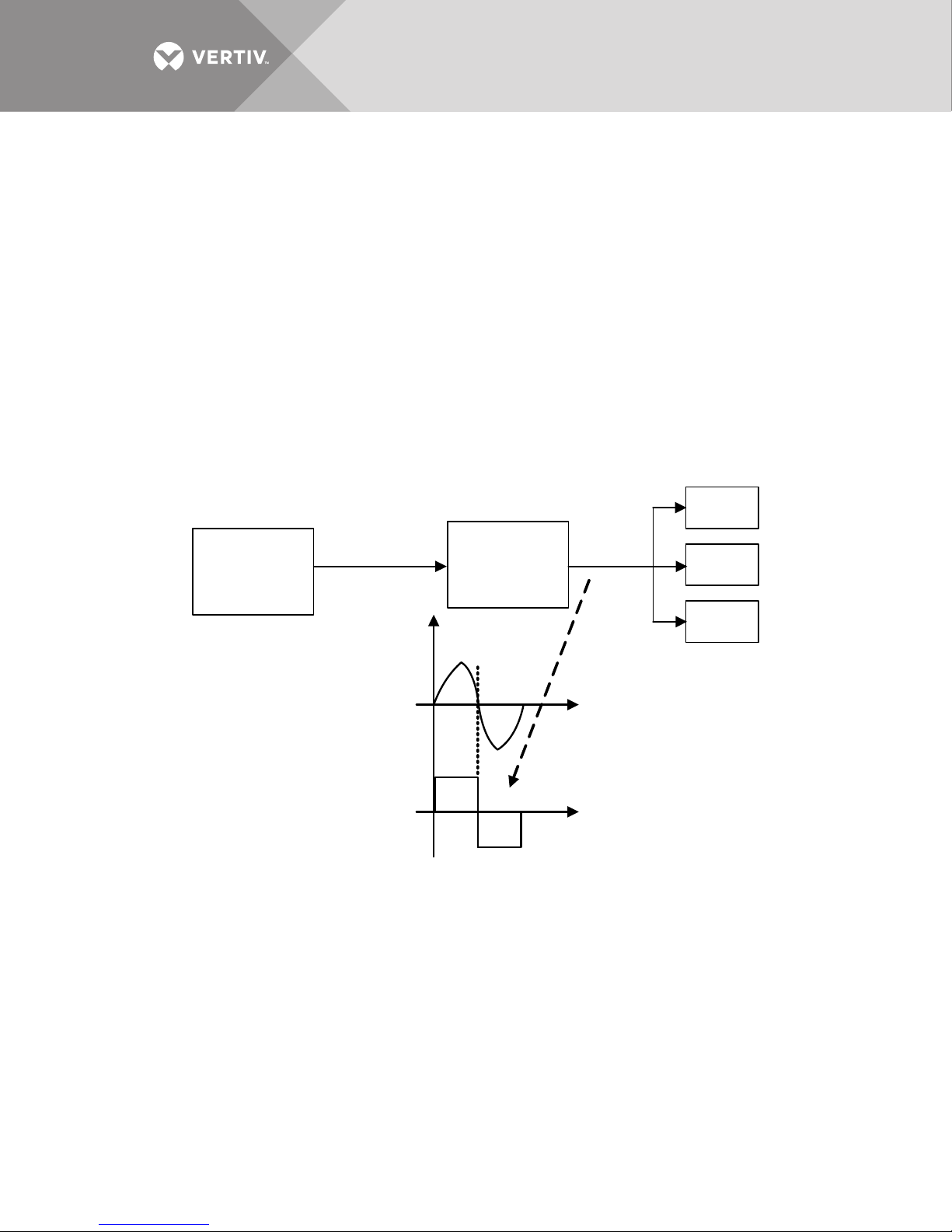
Figure 1 shows the typical block diagram of a UPS system with Liebert MBSM.
Figure 1 Block diagram of a UPS system with Liebert MBSM
Each UPS in the system is supplied by a common electrical bus; the UPS synchronization source
(reference) is the power source connected on its reserve input and, as a consequence, being the
power source common to all the UPS, the inverters outputs will be in synchronization.
When the main power (reserve inputs) fail, each UPS will synchronize the inverter to the signal
coming from the Liebert MBSM (Fref.) and, as a result, the inverters will remain synchronized.
Should the Fref. not be available (or the Liebert MBSM not be installed), each UPS will
synchronize to its own internal quartz oscillator. That would make the inverters outputs
asynchronous.
Vertiv™|Liebert® MBSM™ User Manual | 4
Page 9

The Liebert MBSM has a simple, passive role in relation to the UPS. The UPS will decide on the
source of synchronization on the following priority scale:
• Highest Priority = Local Reserve Input
• Medium Priority = Liebert MBSM Reference
• Lowest Priority = Local Quartz Oscillator
Vertiv™| Liebert® MBSM™ User Manual | 5
Page 10
2.0 INSTALLATION
2.1 Unpacking
NOTICE
The Liebert MBSM should be unpacked where it will be installed. Leaving the packaging intact protects
the Liebert MBSM during transportation.
To unpack the Liebert MBSM:
1. Check the Liebert MBSM for damage and, if any is found, inform the shipper and. if necessary, your Vertiv
agent.
2. Check the nameplate on the Liebert MBSM against the delivery papers and the bill of lading to determine
whether all ordered parts were delivered.
3. Loosen the fastening screws on the pallet.
4. Lift the Liebert MBSM from the pallet.
5. Keep the pallet for repackaging or transportation; dispose of the remaining packaging material in
accordance with local regulations
2.2 Transporting Without Packaging Materials
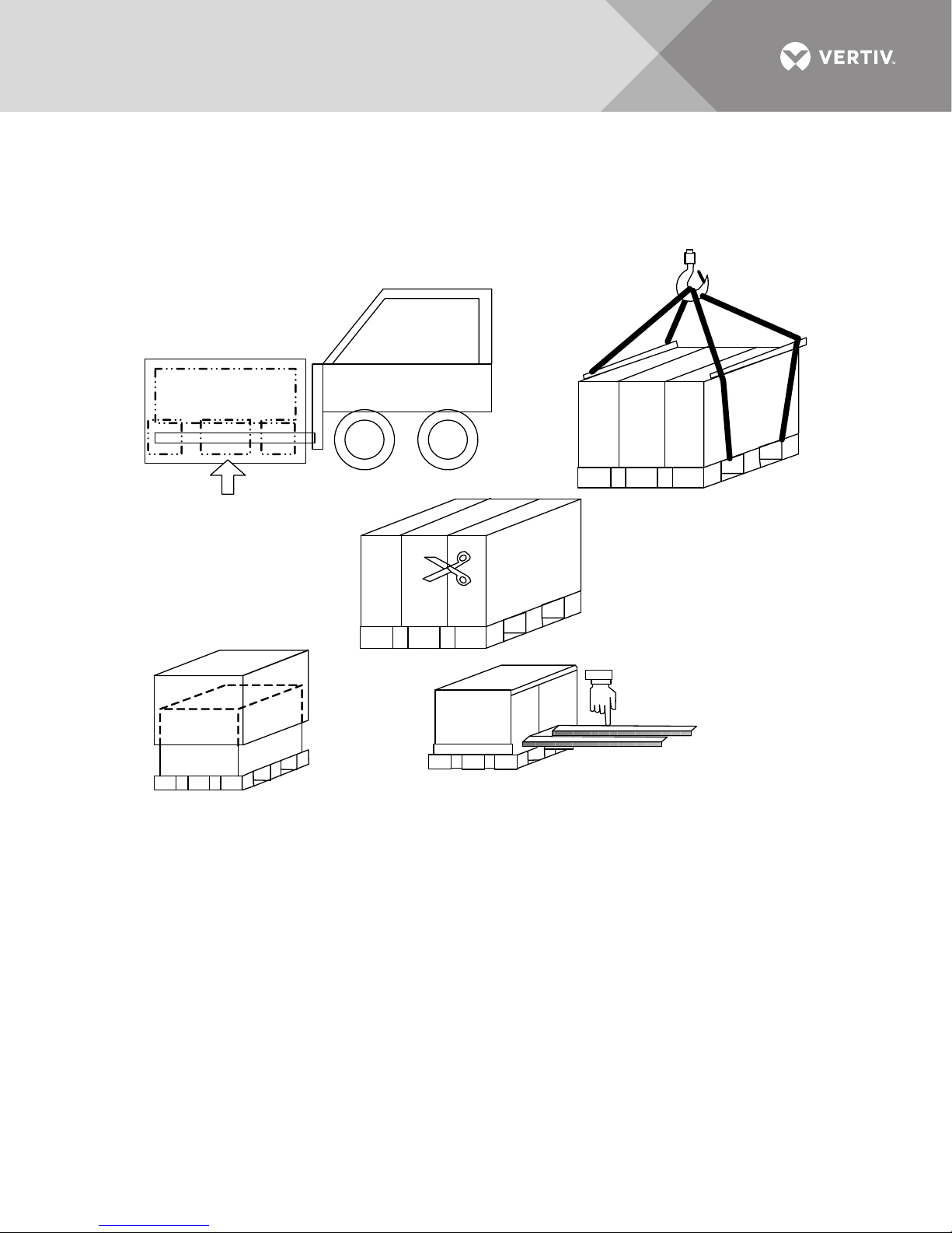
The cabinets can easily be moved to their final destinations with lifting devices.
WARNING
Irregularities in the floor can block the fork lift or cause the Liebert MBSM to bounce off the
forks. Moving the cabinets too quickly can damage them, causing them to fall over and
injure personnel.
WARNING
Whenever the devices are moved they must be secured against sideways tipping.
2.3 Equipment Delivery and Storage
WARNING
Pay attention to the markings indicating the center of gravity of the device. Use suitable
means of transportation and secure the UPS against tipping over when transporting.
Improper transportation can result in damage to the UPS and battery cabinet as well as
injury to personnel.
The Liebert MBSM is shipped on a pallet measuring 31.5" x 47.25" x 7.87"
(800mm x 1200mm x 200mm), and secured by four bolts inserted through its mounting
brackets. It is wrapped in protective plastic sheeting and supported by protective brackets. The
crated Liebert MBSM measures 31.5" x 47.25" x 19.68" (800mm x 1200mm x 500mm and weighs
145.5 lb. (66kg).
Vertiv™|Liebert® MBSM™ User Manual | 6
Page 11
2.4 Storage
If the Liebert MBSM will not be installed immediately, the unit may be kept in its original packaging
in the conditions noted in 2.5.2 - Selecting an Installation Site
Figure 2 Moving the Liebert MBSM
2.5 Configuration for 60Hz 480V AC Applications
2.5.1 Power and Sensing
For 480V 60Hz delta 3-wire plus ground operation, as in the Liebert NX™ 225-600, the Liebert
MBSM auxiliary power and reference sensing voltages must be transformed to 230V singlephase and 415V wye 4-wire plus ground, respectively. This is done via a separate transformer box
provided by Vertiv, Part #552792G1.
Vertiv™| Liebert® MBSM™ User Manual | 7
Page 12

2.5.2 Selecting an Installation Site
The installation site must meet the following conditions:
• Ambient temperature—The ambient temperature should be between 32°F to 104°F (0°C to 40°C).
• Environmental conditions
•No vibration
• Negligible dust
• Non-corrosive atmosphere
•low humidity
• Space requirements
• no required access on either side of the device
2.6 Mount the Liebert MBSM on a Wall
WARNING
If the area where the Liebert MBSM will be installed contains more than 6.6 gal. (25 liters) of
inflammable liquids, refer to HD 384.4.42 S1 A2, Chapter 42 (corresponds to DIN VDE 0100,
Part 420), the area must be contained so that burning liquids or their combustion products
could not spread through the building.
The Liebert MBSM can be wall-mounted, using factory-hangers shown in Figure 3. Attach the
Liebert MBSM to wall studs or other features that can bear its weight. The unit weighs almost 125
lb. (56kg).
Vertiv™|Liebert® MBSM™ User Manual | 8
Page 13
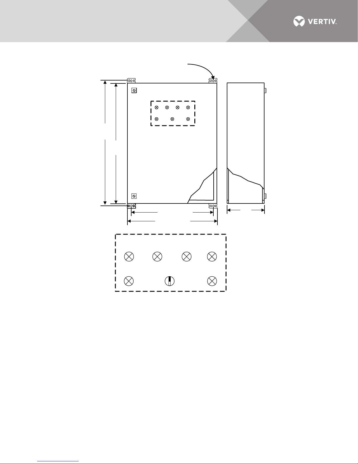
Figure 3 Dimensions, drilling diagram
31.5"
(800mm)
32.7"
(830mm)
Detail A
23.6" (600mm)
21.5" (545mm)
FRONT
Nr. 4 Slot
0.33" x 0.57 ")
(8.5 x 14 .5 mm
Bus A
Active
Bus B
Active
Forced
Bus A
Forced
Bus B
L1
System OK
L2
System
Fault
Priority A Autom. Priority B
9.9"
(250mm)
SIDE
Vertiv™| Liebert® MBSM™ User Manual | 9
Page 14
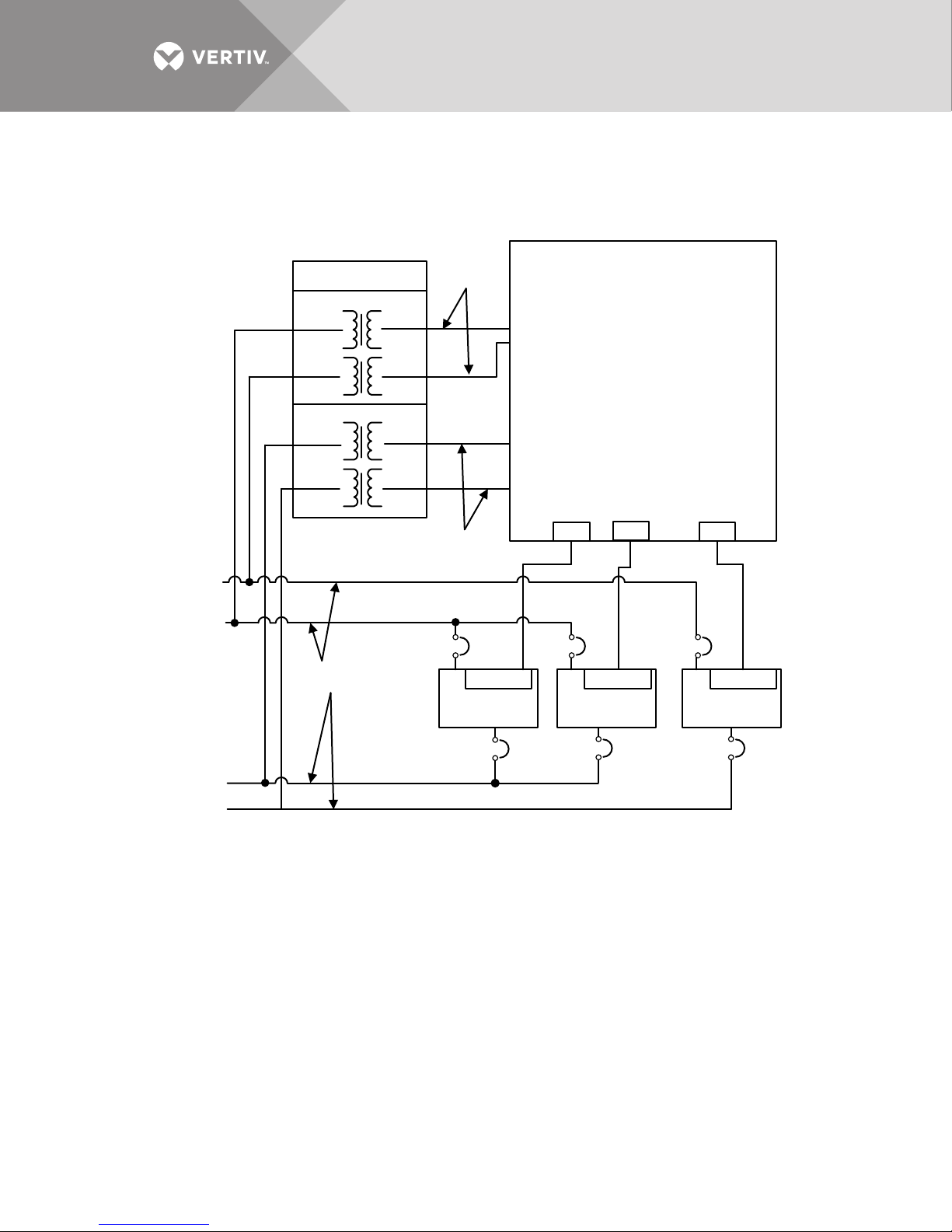
2.6.1 Transformer Box Connections
UPS Module 1
AP30-XP31
UPS Module 2
UPS Module X
Transformer Box
Control Power
Reference Inputs
415V 3 -Phase
4-Wire + Gnd
230V 1 -Phase
Critical
Output
Bus B
Critical
Output Bus A
480V 3-Phase
3-Wire + Gnd
Bypass
Input Line A
Bypass
Input Line B
RJ11 RJ11 RJ11
...
XT1
XT1
XT1
MSBM Box
XP1
...
XPxXP2
AP30-XP31 AP30-XP31
Figures 4 and 5 show the connections between the Liebert MBSM, UPS(s), and transformer box
(the UPS module Bus A versus B assignments are examples only):
Figure 4 Connection example—Liebert MBSM, Liebert EXL S1 and transformer box
Vertiv™|Liebert® MBSM™ User Manual | 10
Page 15
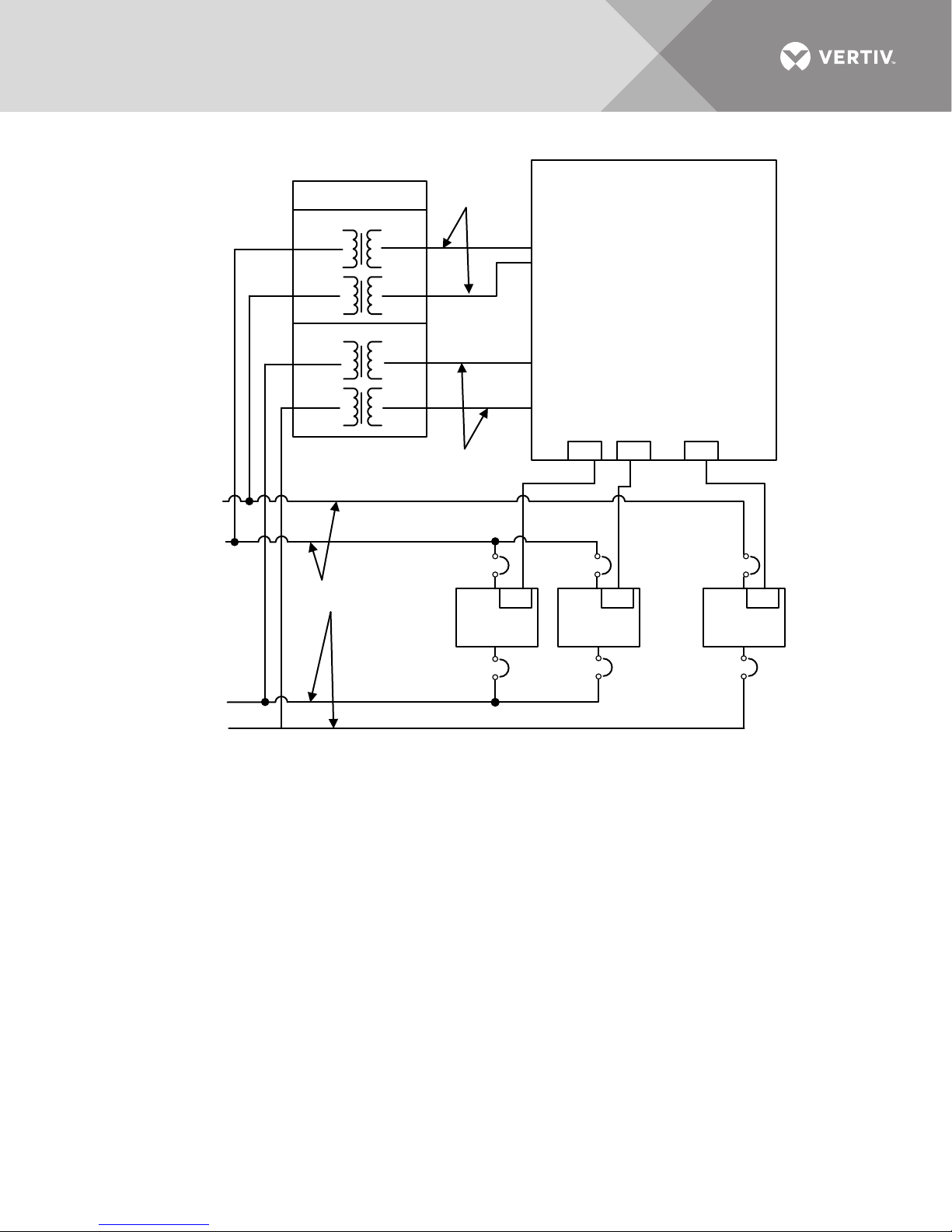
Figure 5 Connection example—Liebert MBSM, Liebert NX and transformer box
UPS
Module 1
X20
UPS
Module 2
X20
UPS
Module X
X20
XPxXP2XP1
XT1
XT1
XT1
MSBM Box
Transformer Box
Control Power
Reference Inputs
415V 3-Phase
4-Wi re + Gnd
230V 1-Phase
Critical
Output
Bus B
Critical
Output Bus A
480V 3-Phase
3-Wire + Gnd
Bypass
Input Line A
Bypass
Input Line B
...
RJ11 RJ11 RJ11
...
Vertiv™| Liebert® MBSM™ User Manual | 11
Page 16
2.7 Dual Bus UPS Systems
Load 2
Load 1
STS 1
STS 2
Liebert
MSBM
Dual Bus
Gen
A
Gen
B
TRA TRB
UPS
System A
UPS
System B
Secure
Bus A
Secure
Bus B
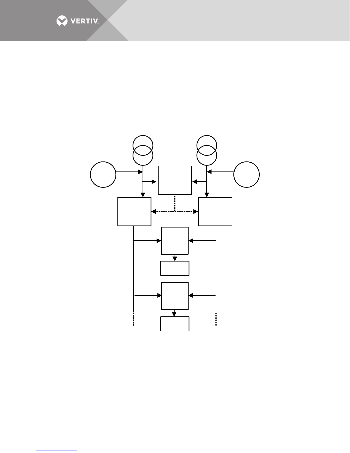
Many modern solutions for critical loads power supply are designed following the dual-bus
architecture (see Figure 6).
This structure is composed basically by two UPS systems (N+N) supplied by two independent
power sources. The two systems outputs are connected to a number of static transfer switches
that provide the automatic selection of one of the two UPS sources to the critical loads.
The static transfer switch transient will not affect the critical load if the UPS sources are
synchronized.
Figure 6 Dual-bus UPS systems
Figure 7 illustrates the main synchronization function components from the system shown in
Figure 6.
Vertiv™|Liebert® MBSM™ User Manual | 12
Page 17
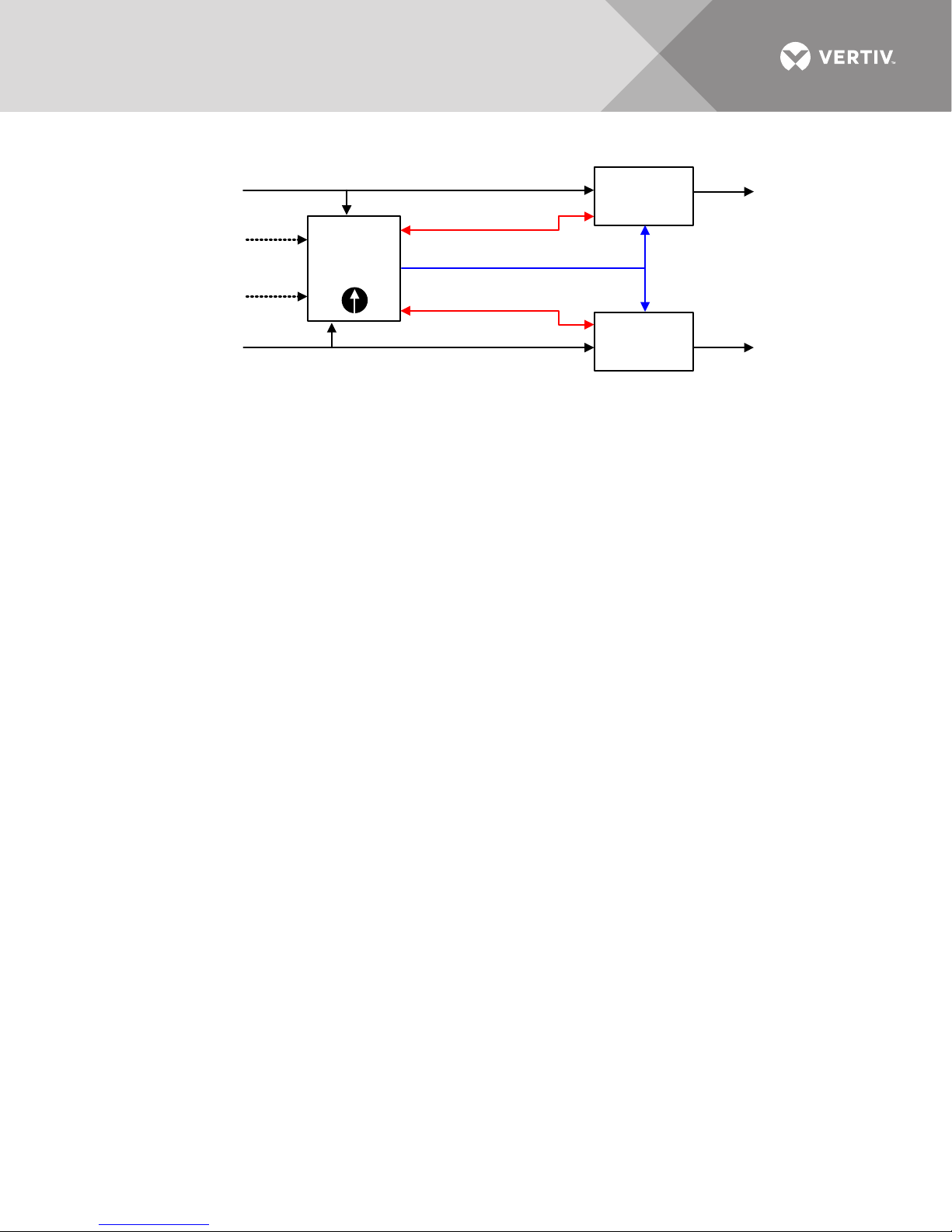
Figure 7 Synchronization Components for Dual Bus System
UPS
System A
UPS
System B
MSBM
Auto
Power Bus A
Power Bus B
Secure
Bus B
Secure
Bus A
System A CNTRL
System B CNTRL
A
B
Bus B
Remote
CNTRL
Bus A
Remote
CNTRL
Frequency Reference
2.7.1 Normal Operating Condition
During normal operation it is assumed that commercial power is present both on Bus A and Bus B
and UPS systems A an B running. Each UPS system performs, in real time, the analysis of the
commercial power present on the relative bus (amplitude and frequency) and gives a feedback
signal to the Liebert MBSM confirming the availability of the bus within the specific electrical
limits.
If one UPS system is shut down, the power bus control is not available: Under this condition, the
power bus related to the UPS system that is shut down is always considered inside limits
(feedback signal to the Liebert MBSM locked to OK condition).
The Liebert MBSM will select one of the two buses to generate the frequency reference. The
reference bus selection is random if both of them are inside preset limits. A manual selector on
the Liebert MBSM permits a priority on one specific bus. This manual selector has three positions:
• Automatic (no priority)
• Priority on Bus A.
• Priority on Bus B.
Should the selected bus fail, the Liebert MBSM will automatically select the other bus
independently from the preferred source selection.
If neither bus is available (not present at all or declared out of limits by the UPS systems), the
Liebert MBSM will source the frequency reference by an internal quartz oscillator tuned on the
system nominal frequency.
2.8 Phase Error Control
During normal operation, each UPS system will synchronize its inverter output to the input power
bus; the Liebert MBSM will constantly monitor the phase error between the two buses making an
indirect measure of the phase difference between the two secure buses.
Should the phase error overtake a preset limit (customizable from 5° to 15°), the Liebert MBSM
will switch to the active mode of operation.
Vertiv™| Liebert® MBSM™ User Manual | 13
Page 18
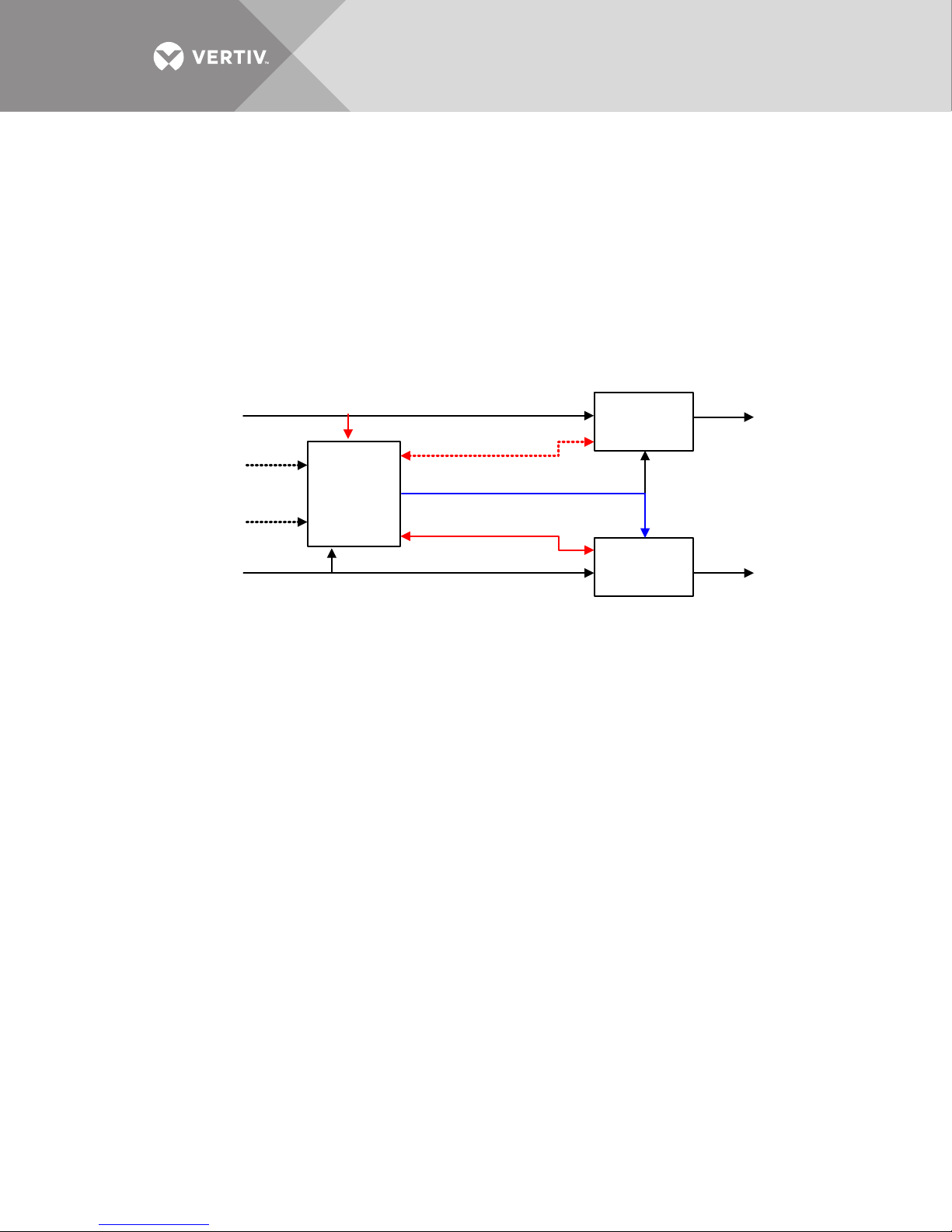
2.8.1 Liebert MBSM Activation on Bus A
UPS
System A
UPS
System B
MSBM
Power Bus A
Power Bus B
Secure
Bus B
Secure
Bus A
System A CNTRL
System B CNTRL
Bus B
Remote
CNTRL
Bus A
Remote
CNTRL
Frequency Reference
Both the power buses are inside limits and the Liebert MBSM is set on the Bus A; this means that
the frequency reference generated by the Liebert MBSM is actually phase referred to the Bus A. If
the phase difference between the two buses is detected over the set limit, the Liebert MBSM will
send a signal to the UPS system B forcing it to synchronize to the generated frequency reference
(see Figure 8).
The UPS A is naturally synchronized with its incoming Bus A, while UPS B is forced by the Liebert
MBSM to sync the frequency reference generated on the Bus A phase reference. The UPS B is
actually out of sync with its own input power bus. UPS B can transfer the critical Bus B on static
bypass input (input power Bus B) but this will cause a critical bus interruption of 20ms.
Figure 8 Synchronizing to Bus A for Dual Bus System
Should the phase error between the two power buses return to the required condition, the Liebert
MBSM will release the CNTRL command, letting System B return to natural operation (Liebert
MBSM returns to passive operation).
2.8.2 Liebert MBSM activation on Bus B
Both the power buses are inside limits and the Liebert MBSM is set on the Bus B; this means that
the frequency reference generated by the Liebert MBSM is actually phase referred to the Bus B. If
the phase difference between the two buses is detected over the set limit, the Liebert MBSM will
send a signal to the UPS system A forcing it to synchronize the generated frequency reference
(Figure 9). The UPS B is naturally synchronized with its incoming Bus B, while UPS A is forced by
the Liebert MBSM to sync the frequency reference generated on the Bus B phase reference. The
UPS A is actually out of sync with its own input power bus. Should the UPS A be in need to
transfer the critical Bus A on static bypass input (input power Bus A), this will be possible with
limited critical bus interruption (20ms).
Vertiv™|Liebert® MBSM™ User Manual | 14
Page 19
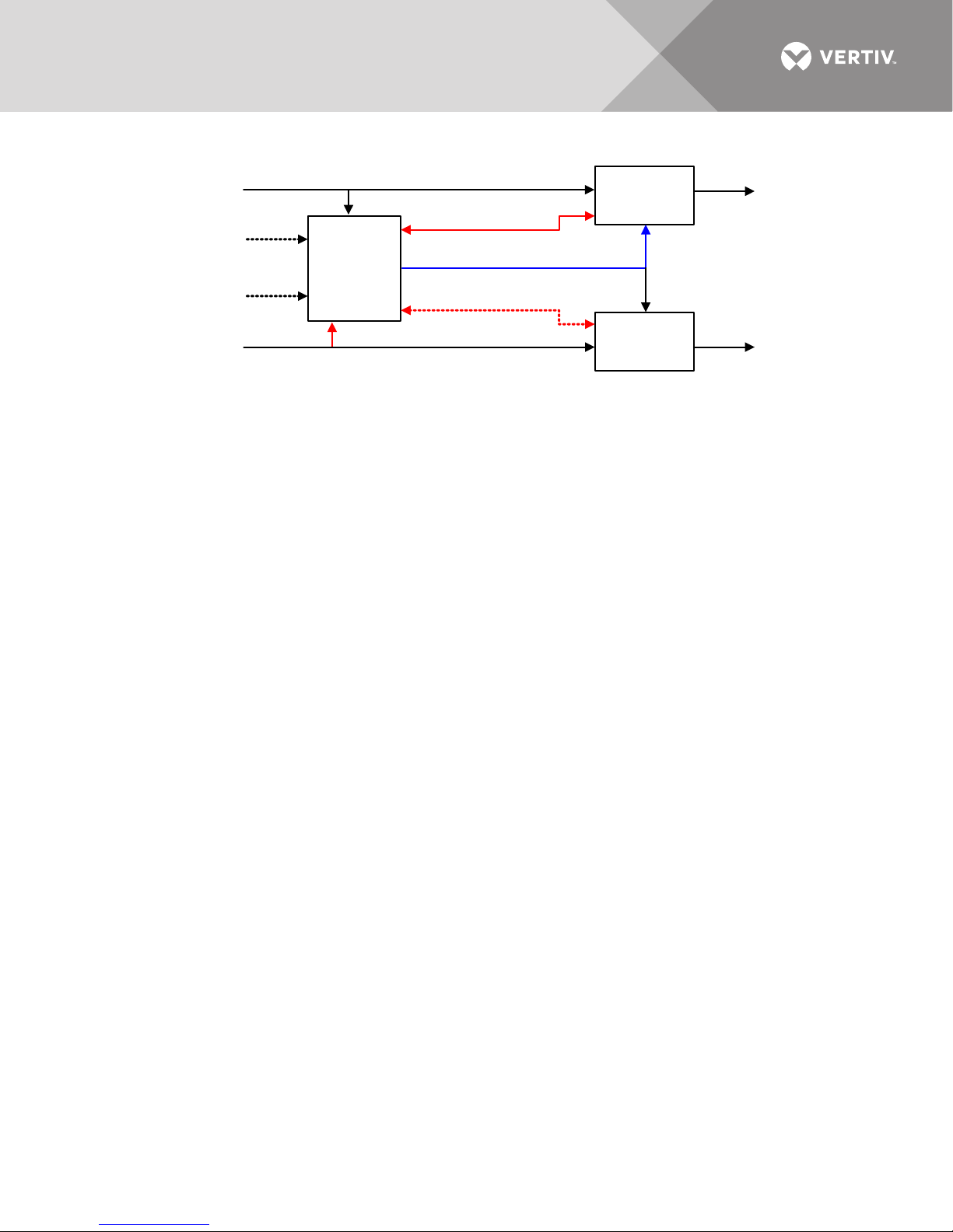
Figure 9 Synchronizing to Bus B for Dual Bus System
UPS
System A
UPS
System B
MSBM
Power Bus A
Power Bus B
Secure
Bus B
Secure
Bus A
System A CNTRL
System B CNTRL
Bus B
Remote
CNTRL
Bus A
Remote
CNTRL
Frequency Reference
Should the phase error between the two power buses naturally come back to set limits, the Liebert
MBSM will release the CNTRL command letting the system A return to natural operation (Liebert
MBSM back to passive operation).
2.9 Generator Operation
If the two power buses are provided by generator backup (see Figure 6), the system behavior is
as follows:
2.9.1 Bus A Failure
If power Bus A fails during normal operation: the Liebert MBSM will automatically select the
power Bus B letting the UPS system A to synchronize the available power Bus B through the
frequency reference. If after a while, the faulty power Bus A is powered back by the generator, the
Liebert MBSM will sense that this new source is not synchronous (normally that is) with the
power Bus B and will keep the system A forced on frequency reference sync. This automatic
behavior is possible only if the local priority switch is in automatic position. Under these
conditions, the Liebert MBSM is naturally capable of preferring the commercial power Bus B as a
synchronization source instead of the generator without external commands needed.
This scenario is represented by Figure 9 and corresponds to the Liebert MBSM Bus B activation.
2.9.2 Bus B Failure
If the power Bus B totally fails during normal operation: the Liebert MBSM will automatically select
the power Bus A letting the UPS system B to synchronize the available power Bus A through the
frequency reference. If after a while, the faulty power Bus B is powered back by the generator, the
Liebert MBSM will sense that this new source is not synchronous (normally that is) with the
power Bus A and will keep the system B forced on frequency reference sync. This automatic
behavior is possible only if the local priority switch is in automatic position. Under these
conditions, the Liebert MBSM is naturally capable of preferring the commercial power Bus B as a
synchronization source instead of the generator without external commands needed.
This scenario is represented by Figure 8 and corresponds to the Liebert MBSM Bus A activation.
Vertiv™| Liebert® MBSM™ User Manual | 15
Page 20

2.9.3 Both Power Bus Failure
Should both power buses be replaced by generator after a fault sequence of both the power
buses, the Liebert MBSM will do the following:
• If local priority switch is on auto, the Liebert MBSM will select one of the two generators as a source for
system synchronization.
• If local priority switch is on a preferred source, that source will be selected, unless the voltage and
frequency values are outside preset limits; under this last condition the second available source will be
selected anyway, independently from the switch position.
• If both sources are detected outside set limits, the Liebert MBSM will generate the frequency reference
by the local quartz oscillator.
• If the two power buses are supplied from a common generator and inside set limits, the Liebert MBSM will
operate as per normal conditions and checks
Vertiv™|Liebert® MBSM™ User Manual | 16
Page 21
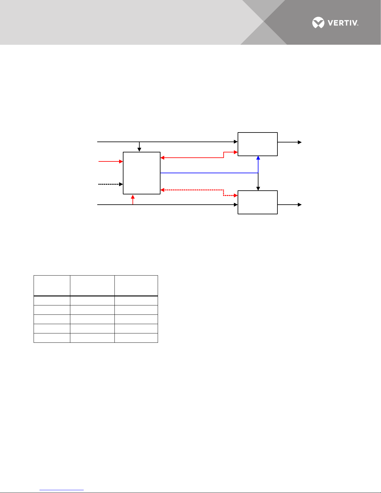
2.9.4 Remote Commands
UPS
System A
UPS
System B
MSBM
Power Bus A
Power Bus B
Secure
Bus B
Secure
Bus A
System A CNTRL
System B CNTRL
Bus B
Remote
CNTRL
Bus A
Remote
CNTRL
Frequency Reference
During particular operating conditions (such as the generator supply), there are two remote
commands available: each command is capable to exclude one power bus reference overriding
the Liebert MBSM controls and forcing the related UPS system to phase lock the Liebert MBSM
frequency reference. If both the power buses are excluded by the remote commands, the UPS
systems will phase lock the frequency reference self-generated by the Liebert MBSM internal
quartz oscillator. Figure 10 shows an example of Bus A remote control activation.
Figure 10 Remote override to synchronize to Bus B for dual-bus system
2.10 Application Limits
The Liebert MBSM with phase control (10B14545G1) is applicable to systems with up to six UPS
modules.
Table 1 Liebert MBSM application limits—Six UPS modules
Combinati
on
A5 1
B4 2
C3 3
D2 4
E1 5
Vertiv™| Liebert® MBSM™ User Manual | 17
Bus A
Maximum
UPS Number
Maximum
UPS Number
Bus B
Page 22
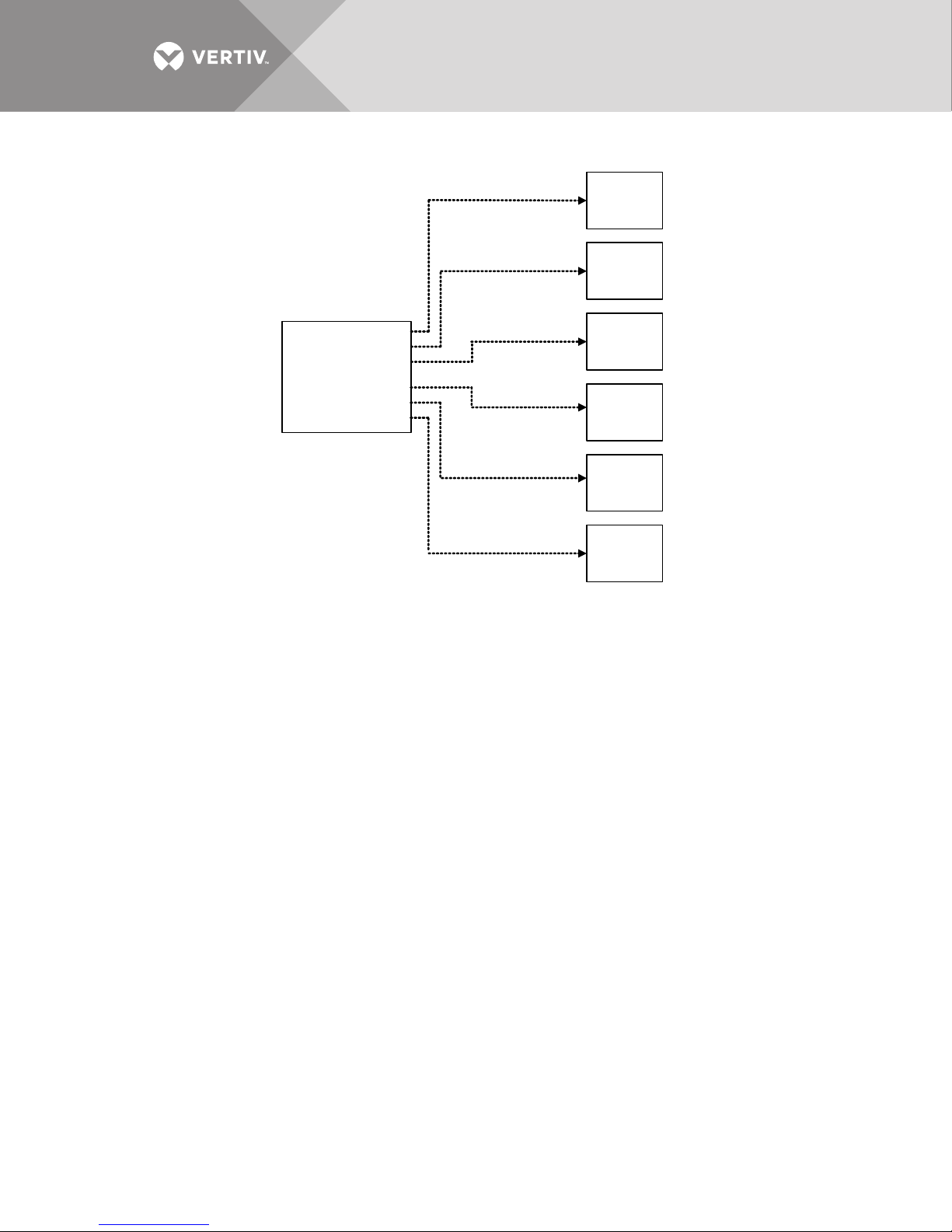
Figure 11 Liebert MBSM connected to six UPS modules
Liebert MBSM
10B14545G1
UPS #1
UPS #2
UPS #3
UPS #4
UPS #5
UPS #6
Vertiv™|Liebert® MBSM™ User Manual | 18
Page 23
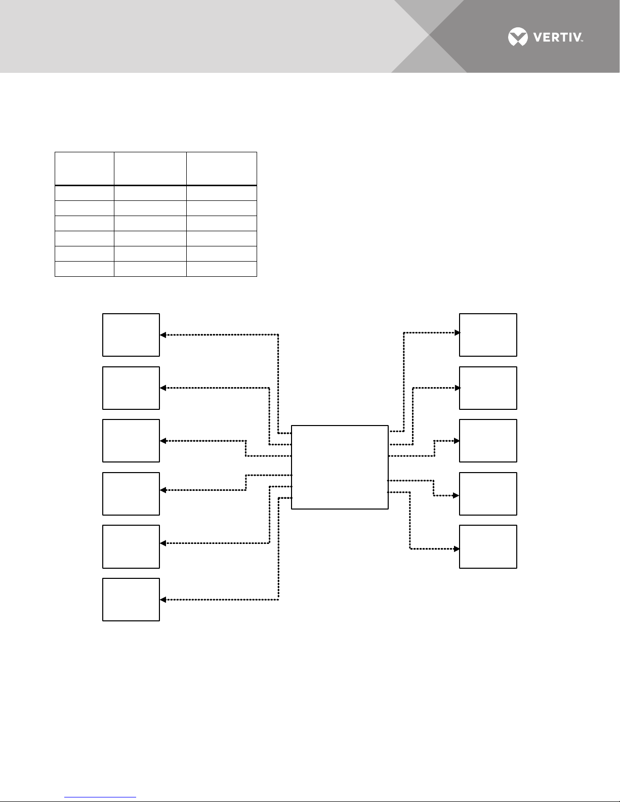
2.10.1 Special Solution, if Required
Liebert MBSM
10B14545G2
UPS #1
UPS #2
UPS #3
UPS #4
UPS #5
UPS #6
UPS #7
UPS #8
UPS #9
UPS #10
UPS #11
Note that the maximum number
of UPS’s in modular parallel is
A special version of the Liebert MBSM (10B14545G2) with phase control is available for
applications with up to 11 UPS modules.
Table 2 Liebert MBSM application limits—11 UPS modules
Combinati
on
A8 3
B7 4
C6 5
D5 6
E4 7
F3 8
Bus A
Maximum
UPS Number
Figure 12 Special application—Liebert MBSM connected to 11 UPS modules
Bus B
Maximum
UPS Number
2.11 Selecting the Priority
Use the selector switch on the front panel to set the operating mode:
• AUTOMATIC (AUTOM.)—Liebert MBSM detects the reference bus automatically, without assigning a
priority; the first bus to be detected is selected as the reference.
• PRIORITY BUS A (PRIORITY A)—If Bus A is present it is selected as priority source. If Bus A is not
present, the Liebert MBSM selects Bus B, if present.
• PRIORITY BUS B (PRIORITY B)—If Bus B is present it is selected as priority source. If Bus B is not
present, the Liebert MBSM selects Bus A, if present.
Vertiv™| Liebert® MBSM™ User Manual | 19
Page 24
2.12 Remote Commands
There are two normally open inputs provided on XT1 for remote commands. These inputs are
biased at 230VAC. Relays used to close them must be rated accordingly.
2.12.1 Excluding Bus A
When the corresponding terminal voltage-free contact is closed, the Liebert MBSM is forced onto
Bus B and the UPS A system follows the reference signal generated by the Liebert MBSM.
2.12.2 Excluding Bus B
When the corresponding terminal voltage-free contact is closed, the Liebert MBSM is forced on
to Bus A and the UPS B system follows the reference signal generated by the Liebert MBSM.
2.12.3 Excluding Bus A and B
When both contacts are closed, the Liebert MBSM reference signal is generated by an internal
quartz oscillator. Both UPS systems will follow the reference signal generated by the Liebert
MBSM.
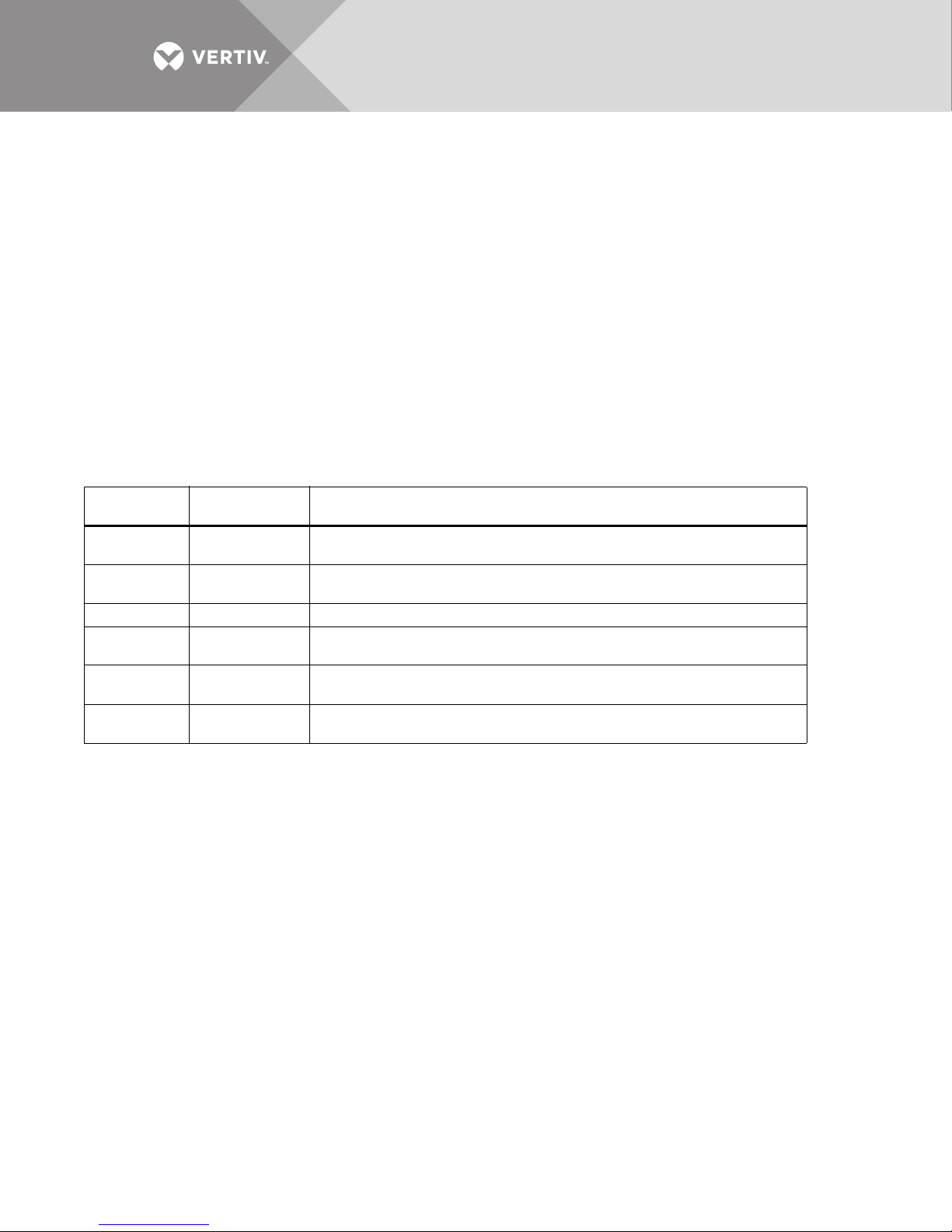
Table 3 Lamp indications
Normal
Lamp Title
Bus A Active Off
Bus B Active Off
L1 System OK On System OK —
L2 System
Fault
Forced Bus A Off
Forced Bus B Off
Condition Non-Condition
On indicates synchronization on Bus A and Bus B forced to A due to buses
OOS detected
On indicates synchronization on Bus B and Bus A forced to B due to buses
OOS detected
Off On when both buses not available or system fault
On indicates synchronization on Bus A and Bus B forced to A by external
command
On indicates synchronization on Bus B and Bus A forced to B by external
command
Vertiv™|Liebert® MBSM™ User Manual | 20
Page 25
3.0 INSTALLATION
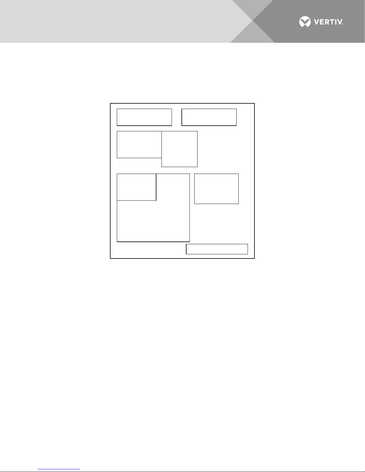
Input Fuses
Contactors
Timers
AP1
System
Synchronization
Control
15B10777G2
AP2
SSW CTRL
15B10890G1
AP3
Synchronism
Detector
15B10889G1
Terminals XT1
Auxiliary Supply Relays Logic
3.1 Liebert MBSM Internal Layout
Figure 13 Liebert MBSM internal layout
Vertiv™| Liebert® MBSM™ User Manual | 21
Page 26
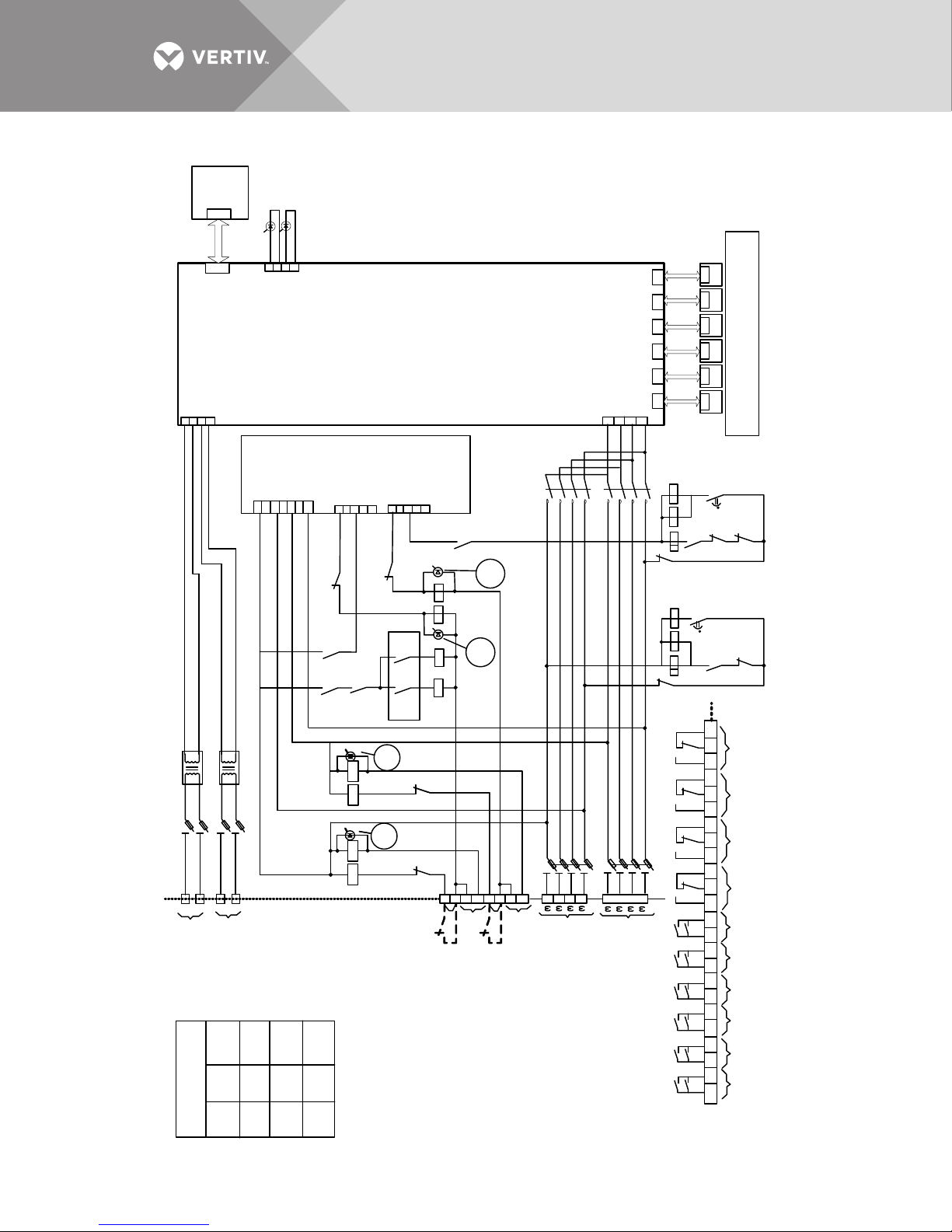
Figure 14 Schematic diagram
UPS1
AP1
UPS2
AP1
UPS3
AP1
UPS4
AP1
UPS5
AP1
UPS6
AP1
21 22 23 24 25 26 27 28 29 30 31 32 33 34 35 36 37 38 39 40 41 42 43 44
R4/1 R4/2
R4/3
R4/1
R4/2
R4/3
58
59
61
60
Priority Actived
Bus A
Bus A
Selected
Bus B
Selected
45
46
47
48
49
50
51
52
53
54
55
56
57
62
63
65
66
64 6 7
68
RHA/1 RHA/2 RHA/3
RHB/1 RHB/2 RHB/3
RPA/2
RPB/2
RSA/3
RSB/3
567
8
567
8
050607
08
F5F6F7
3 x Fuse 6A
123
4
567
8
010203
04
F1
F2
F3
Link
Link
3 x Fuse 6A
13141516171819
20
AB
A1 B1
A
B
A1 B1
09
010
011
012
171819
20
F12
F11
F10
F9
9
101112
9
101112
01
04
05
08
L3
L4
Y
Y
30
32
33 3 5
00
00
00
From Output Busbar 1
From Output Busbar 2
220-240V/50-60Hz
220-240V/50-60Hz
2 x Fuse 4A
TM1
TM2
XT1
2 x Fuse 4A
R6/4R4/4
31
34
08
124
5
1M
1M
1234567
AP3
2M
3M
12345
341
2
414243
44
System OK
System Faul t
+
+
-
-
6M
AP2
FL 34W
7PL
7PL
L1
L2
R
G
AP1
Liebert MBSM with Phase Control
(up to 6 UPS Modules)
RP A
RP B
RHB
RHA
SW1 /1 SW1 /2
R2/2
41A
40
04
39
38
On the
Door
43A
42A
L5
Y
L6
05
Y
R1/2
RSA/2
R2/3
R1/3
37
037
36
038
* From UPS A Reserve OK
Cl ose For ced o n S ource B
Close Forced on Source A
* From UPS B Reserve OK
R1
R4 R2 R6
Bu s B
Active
Forced
Bus A
K2
K1
131415
16
12345
135
7
4M
RJB1RJA1
RJC 1
RJD 1 RJE 1 RJF1
44
RPB /1
RPA/1
21 25
R1/1
RSA/1
2927
26
R2/1
28
24
23
K2 K1
K1RSA
K2RS BT2
X
T1
X
From Reserve
Input Line A
380=415V/50-60Hz
From Reserve
Input Line B
380=415V/50-60Hz
Bus A
Act ive
RSB/1
XT1
T1
1
T2
1
OFF OFF Automatic
Input A / In put B = OK
R1 = R2 = ON
SW1/1 SW1/2 Priority
ON OFF P = A
OFF ON P = B
00
Forc ed
Bus B
Inhibit UPS A/1
Inhibit UPS A/2
Inhibit UPS A/3
Inhibit UPS B/1
Inhibit UPS B/2
Inhibit UPS B/3
Priority Actived
Bus B
Vertiv™|Liebert® MBSM™ User Manual | 22
Page 27
4.0 UPS SETUP
Input Line A
Force
Source B
Force
Source A
XT15
XT16
XT19
XT20
XP1
XP2
XP6
MBSM
With
Phase Control
Input Line A
Power System B
Single UPS
UPS B
BUS B
Digital Input
INHBIT UPS A1
INHBIT UPS A2
INHBIT UPS A3
INHBIT UPS B1
INHBIT UPS B2
INHBIT UPS B3
BUS A
UPS A1
AP30-XP31
Digital Input
UPS A2
Digital Input
Power System A
Two UPS’s in
Parallel Configuration
Digital Input :
EXL S1 = AP30
or AP 202-XP11
Sync
AP30-XP31
Each UPS comprising System A and System B must be set up via PPVis according to the
following.
4.1 Liebert MBSM Function Activation
If the Liebert MBSM installation is going to be done on a UPS system already in service and the
synchronization functionality was not present before, a detailed procedure by qualified Vertiv
personnel is required.
4.2 Liebert MBSM Interconnections
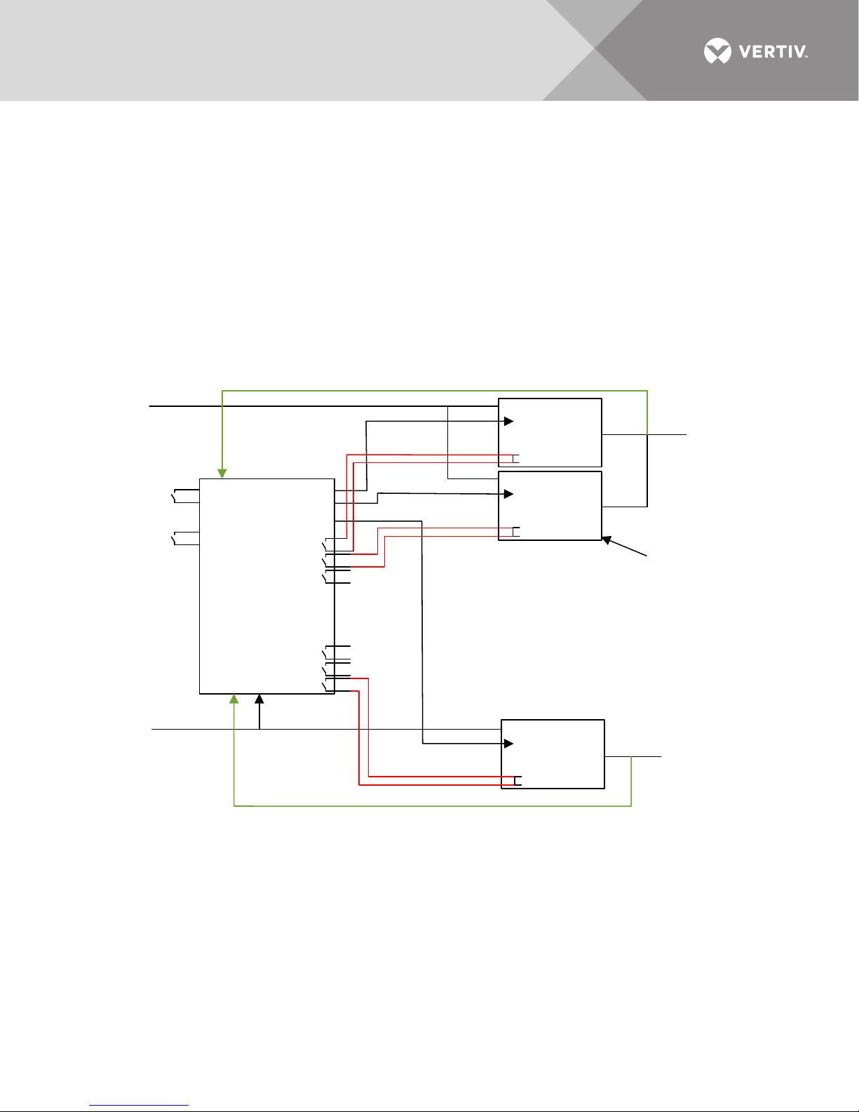
Figure 15 Liebert MBSM Interconnections to Liebert EXL S1 Dual Bus system
Vertiv™| Liebert® MBSM™ User Manual | 23
Page 28
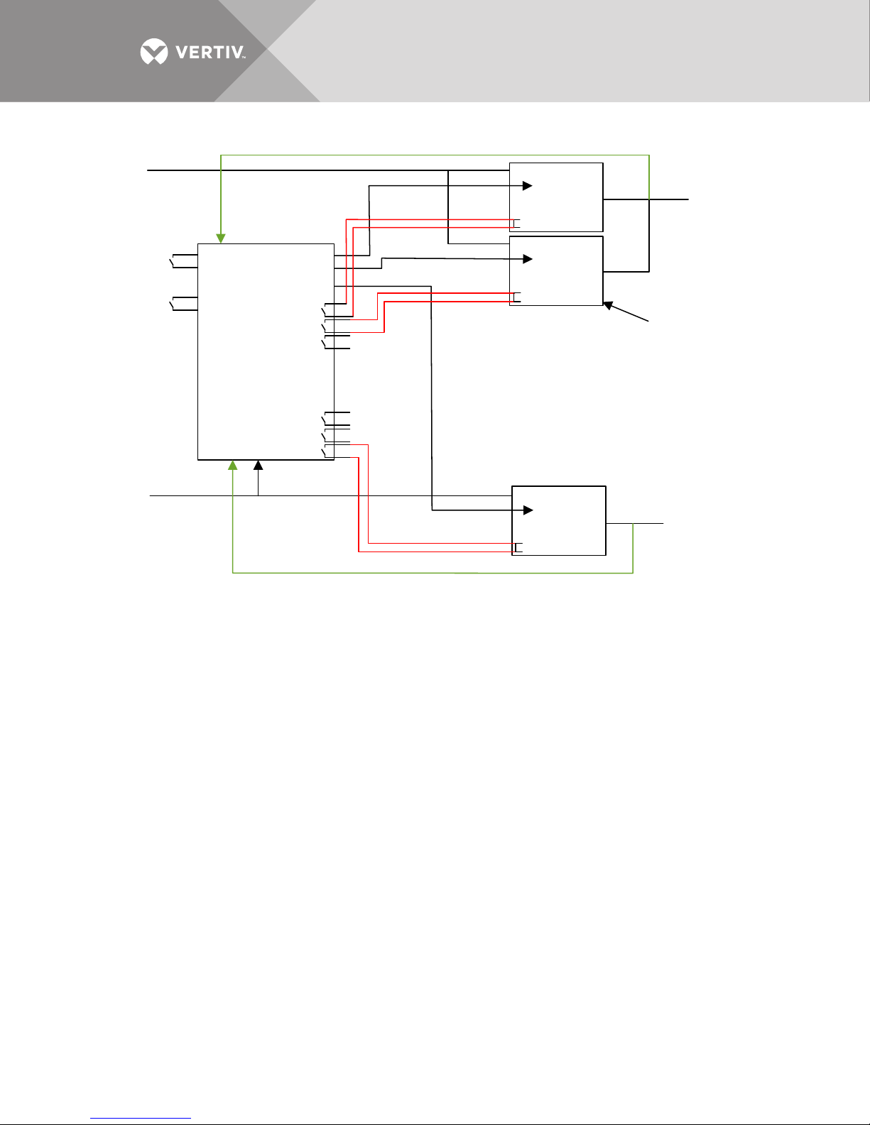
Figure 16 Liebert MBSM Interconnections to Liebert NX Dual Bus system
Input Line A
Force
Source B
Force
Source A
XT15
XT16
XT19
XT20
XP1
XP2
XP6
MBSM
With
Phase Control
Input Line A
Power System B
Single UPS
UPS B
Sync
BUS B
Digital Input
INHBIT UPS A1
INHBIT UPS A2
INHBIT UPS A3
INHBIT UPS B1
INHBIT UPS B2
INHBIT UPS B3
BUS A
UPS A1
Sync
Digital Input
UPS A2
Sync
Digital Input
Power System A
Two UPS’s in
Parallel Configuration
Digital Input :
NX225 -600 = TB1
Figures 15 and 16 are examples of a dual-bus system composed of a modular parallel on Bus A
and a single unit on Bus B.
4.3 Power Interconnections
The Liebert MBSM is powered by the two main buses and from the two critical buses (UPS
outputs).
Main Bus A is a three phase +N line from the Transformer Box Reference Output (as shown in
2.6.1 - Transformer Box Connections) to be interconnected to the Liebert MBSM XT1 terminals
1[a], 2[b], 3[c] and 4[N]. The phase sequence MUST be the same of the UPS A reserve input.
Suggested wire size is 14AWG, protected with 10A Class CC fuse.
Main Bus B is a three phase +N line from the Transformer Box Reference Output (as shown in
2.6.1 - Transformer Box Connections) to be interconnected to the Liebert MBSM XT1 terminals
5[a], 6[b], 7[c] and 8[N]. The phase sequence MUST be the same of the UPS B reserve input.
Suggested wire size is 14AWG, protected with 10A Class CC fuse.
AUX supply A is a single phase line coming from the UPS A output via the Transformer Box
Control Power (as shown in 2.6.1 - Transformer Box Connections), to be interconnected to the
Liebert MBSM XT1 terminals 9[L] 10[N]. Suggested wire size is 14AWG, protected with 10A Class
CC fuse.
AUX supply B is a single phase line coming from the UPS B output via the Transformer Box
Control Power (as shown in 2.6.1 - Transformer Box Connections), to be interconnected to the
Liebert MBSM XT1 terminals 11[L] 12[N]. Suggested wire size is 14AWG, protected with 10A Class
CC fuse.
Vertiv™|Liebert® MBSM™ User Manual | 24
Page 29

4.4 Signal Interconnections
UPS inhibition signals are contacts present in the Liebert MBSM to be wired to each digital input
of each UPS installed.
Bus A UPS digital input must be wired to the Liebert MBSM outputs XT1 from 21 to 26. Bus B UPS
digital input must be wired to the Liebert MBSM outputs XT1 from 27 to 32. See also Figures 15
and 16 red signal interconnections. Suggested wire size is 16AWG.
Frequency reference signals are signals available on the Liebert MBSM RJ-45 plugs XP1~ XP6.
Each UPS is equipped with an RJ-45 on the control PCB. Each UPS RJ-45 must be
interconnected to an RJ-45 XPx plug on the Liebert MBSM using a cable with the following
characteristics:
• cable type: category 5 shielded flexible stranded
• wires: 4 x 2 x AWG24 copper cable
• shielding: aluminum/polyester
• impedance: 100Ohm
• connectors: 2 x shielded RJ-45 plugs
• connections: pin-to-pin
As the length of these cables depends upon the UPS system layout, these cables are not
normally supplied by Vertiv. For this interconnection use only shielded RJ-45 cables and, possibly,
do not run these cables in the same conduit where the power cables are running. The max
theoretical length of each frequency reference cable should not exceed 100m.
4.5 Remote Contacts
Two remote contacts are available for the customer to use:
• Bus A forced = XT1 19-20
• Bus B forced = XT1 15-16
If these remote contacts/commands are not used, leave the mentioned terminals not wired. Once
these inputs are open, the Liebert MBSM will logically behave normally.
Vertiv™| Liebert® MBSM™ User Manual | 25
Page 30
7PL
7PL
AP2
Board
CHL0413170
F
L
3
4
W
6M
System OK
System Fault
341
2
44 -
43 +
42 -
41 +
L2
L1
G
R
XP1 XP2 XP3 XP 4 XP3 XP 4
RJ-45RJ-45RJ-45RJ-45RJ-45RJ-45
RJ-45
XP7
4M
135
7
AP1
UPS5
AP1
UPS4
AP1
UPS3
AP1
UPS2
AP1
UP S1
Liebert MBSM with Phase Control
(Up to 11 UPS Modules)
Intern al Cable Size: 1.5mm
2
3.H 2
K2RSBT2 K2RSB
T2
567
8
13141516171819
20
RPA
RP B
RHA1RHB
RHB1 RH A
R1/3
R2/3
12345
12345
2M
3M
37
36
38
08
Y
RSB/1
Bus B
Active
K1
01020304050607
08
K1
K2
K2
Bus A
Active
Y
39
40
04
01020304050607
08
01020304050607
08
F1F2F3
F5F7F6
Link
Link
3 x Fuse 5A
3 x F us e 5A
34
08
31
R1/2
R2/2
RSA/2
Forced
Bus A
Y
R6/1
SW1/1
SW1/2
On the
Door
43A
41A
42A
R2 R6 R7
33 3 3 33
Forced
Bus B
Y
R1 R4 R5
30 32 32
R4/1
01
04
05
06
2 x Fuse 4A
091110
12
F9
F11
F10
F12
091110
12
171918
20
2 x Fuse 4A
TM1
TM2
AA1A
A1
BB1B
B1
12
11
10
9
44
21
23
24
T1
1"
R1/1
RSA/1
T2
1"
R2/1
RPB/1
RPA/1
25
29
26
27
28
1234567
1M
AP3
Synchronism Detector
(P.N. 15B10889G1)
Dwg. 15H70853
AP1
Sy st em S ync hro nizat io n
Control B oard
(P.N. 15B10777G2)
Dwg. 15H70783
124
5
[4.F9][4.F9]
1M
131415
16
XT1
From Output Busbar 1
From Output Busbar 2
220-240/50-60Hz
220-240/50-60Hz
(L)
(L)
(M)
(M)
From UPS A Reserve OK
Fr om UPS B Re ser ve OK
Close Forced on Source B
Close Forced on Source A
From Reserve
Inp ut Li ne A
380-415/50-60Hz
From Reserve
Inp ut Li ne B
380-415/50-60Hz
(W)
(U)
(V)
(N)
(W)
(U)
(V)
(N)
123
4
Refe rence B us
Inpu ts
Contro l Power
(1 Inp ut fr om Eac h
Critical Bus Output)
OFF OFF Automatic
Input A / Input B = OK
R1 = R2 = ON
SW1 SW2 Priority
ON OFF P = A
OFF ON P = B
10H72985
Pg. 3, Rev. 1
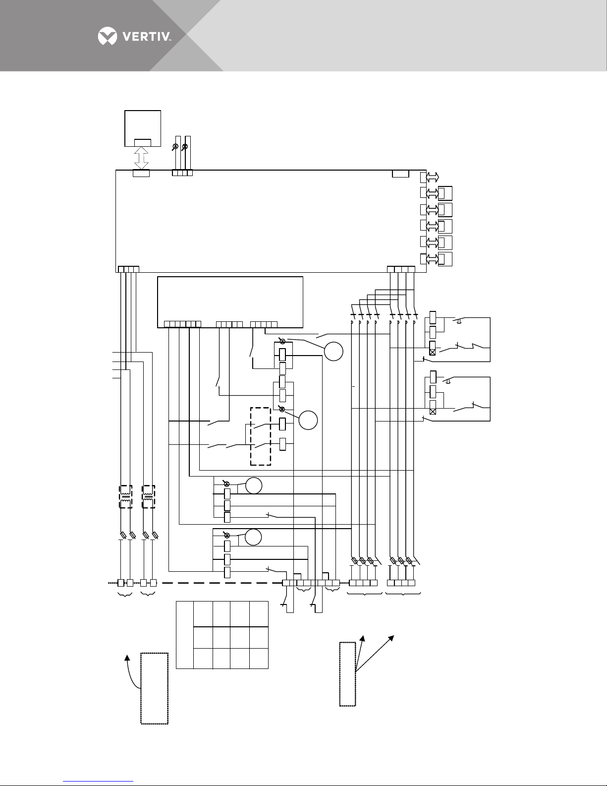
Figure 17 Liebert MBSM Control Module
Vertiv™|Liebert® MBSM™ User Manual | 26
Page 31
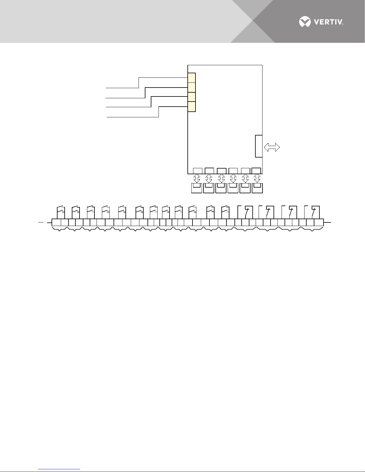
Figure 18 MBSM with phase control, up to 11 units
21 22 23 24 25 26 210 220 230 240 250 260 27 28 29 30 31 32 270 280 290 300 310 320 33 34 35 36 37 38 39 40 41 42 43 44
45
46
47
48 50 460 480 500 52 54 56 540520 560 59
58 61
62
64
65
67
68
RJ-45
XP7
[3.L3]
XP
RJ45
XP
RJ45
XP
RJ45
XP
RJ45
XP
RJ45
XP
RJ45
UPS7
AP1
UPS6
AP1
UPS8
AP1
UPS9
AP1
UPS10
AP1
UPS11
AP1
5 4 2 1
17
18
19
20
1M
10H72985
Pg. 4, Rev. 1
Bus B
Selected
Bus A
Selected
Priority Actived
Bus A
Priority Actived
Bus B
Inhbit UPS B/6
Inhbit UPS B/5
Inhbit UPS B/4
Inhbit UPS B/3
Inhbit UPS B/2
Inhbit UPS B/1
Inhbit UPS A/6
Inhbit UPS A/5
Inhbit UPS A/4
Inhbit UPS A/2
Inhbit UPS A/1
Inhbit UPS A/3
RH/1 RH/2 RH/3 RH/1 RH/2 RH/3 RH/1 RH/2 RH/3 RH/1 RH/2 RH/3 RH/2 RH/2 RH/3 RH/2
XT1
R4/2 R4/3 R4/4 R5/2 R5/3R5/1 R6/2 R6/3 R6/4 R7/2 R7/3R7/1
49 470450 53490 51 55 510 57 60 63 66530
550
AP10
SYSTEM SYNCHRONIZATION
CONTROL BOARD
(P.N. 15B10777G2)
DWG. 15H70783
Vertiv™| Liebert® MBSM™ User Manual | 27
Page 32

Notes
Vertiv™|Liebert® MBSM™ User Manual | 28
Page 33

Page 34

VertivCo.com | Vertiv Headquarters, 1050 Dearborn Drive, Columbus, OH, 43085, USA
© 2018 Vertiv Co. All rights reserved. Vertiv and the Vertiv logo are trademarks or registered trademarks of Vertiv Co. All other names and logos referred to
are trade names, trademarks or registered trademarks of their respective owners. While every precaution has been taken to ensure accuracy and
completeness herein, Vertiv Co. assumes no responsibility, and disclaims all liability, for damages resulting from use of this information or for any errors or
omissions. Specifications are subject to change without notice.
SL-30106_REV1_8-18
 Loading...