

Page 1

Liebert® LPC Series
Precision Air Conditioning
User Manual
Page 2

Vertiv I Liebert LPC I User Manual
Copyright by Vertiv Co. Ltd.
The content in this document is subject to change without notice. All rights, including rights
of translation, reproduced by printing, copying or similar methods, and even of parts, are
reserved. Violators will be liable for damages. All rights, including rights deriving from patent
license or registration of a utility model or design, are reserved. No part of this document may
be reproduced or transmitted in any form or by any means without the prior written consent
of Vertiv Co. Ltd.
Notice
The purchased products, services, and features are stipulated by the contract made between
Vertiv Co. and the customer. All or part of the products, services, and features described in
this document may not be within the purchasing scope or the usage scope. Unless otherwise
specified in the contract, all statements, information, and recommendations in this document
are provided "AS IS" without warranties, guarantees or representations of any kind, either
express or implied. The information in this document is subject to change without notice.
Every effort has been made in the preparation of this document to ensure the accuracy of
the contents, but all statements, information, and recommendations in this document do not
constitute a warranty of any kind, express or implied.
Vertiv Co., Ltd.
• China
Website:
E-mail:
Customer service hotline: 4008876510
• Asia Pacific
Homepage: www.vertivco.com
E-mail:
For Technical Support, users may contact the nearest Vertiv Co. local sales office or service
www.Vertivco.com
centre.
2
Page 3
Vertiv I Liebert LPC I User Manual
note indicates a
result in death or injury. It also indicates
instructions that need to be adhered to, failing
which may result in danger and safety issues
related to physical injury, the content under the
Warning heading is used for precautions which
section indicates additional and useful
protocols that are standardized and help make
maximum utilization of the resources at hand.
also comes under the Note heading helping the
users get to grips with the definitions, concepts,
Purpose of the Document
This document applies to the series of precision air conditioners and cooling solutions which
maintain an optimal environmental control of technological ecosystems at minimal operating
costs. This document gives an overview of the specifications, installation, and commissioning
& maintenance procedures with troubleshooting from the user perspective. The figures used
in this document are for reference only.
Please read this manual carefully before installing, maintaining, and troubleshooting.
Styling used in this Guide
The styles used in the manual will be defined as mentioned in the following table:
Situation Description
The
Warning/Danger/Caution
hazardous or potentially harmful situation that can
Warning/Danger/Caution
thereby having an adverse effect on the reliability
of the device and security. Even for practices not
need to be taken which, otherwise, could result in
equipment damage, performance degradation, or
interruption in service.
The
Note
Note
information, including tips and tweaks. It also calls
attention to best practices and industry-best
Helpful information related to the mainstream stuff
Version History
Issue Revision Change
31013548 V1.0 -
and terminologies used in the manual.
3
Page 4

Vertiv I Liebert LPC I User Manual
Table of Contents
1 Product Overview .............................................................................. 10
1.1
Product Introduction .....................................................................................................10
1.2
Model Description ........................................................................................................... 11
1.3
Model Nomenclature ..................................................................................................... 12
1.4
Components ..................................................................................................................... 13
1.4.1 Compressor .............................................................................................................................................................................. 13
1.4.2 Evaporator ................................................................................................................................................................................. 13
1.4.3 Electronic Expansion valve (EEV) ...................................................................................................................... 14
1.4.4 EC Fans ......................................................................................................................................................................................... 14
1.4.5 Infrared Humidifier ............................................................................................................................................................ 15
1.4.6 Electric Heaters .................................................................................................................................................................... 15
1.4.7 Filter-driers ................................................................................................................................................................................ 16
1.4.8 Controller .................................................................................................................................................................................... 16
1.4.9 Liquid Indicator ...................................................................................................................................................................... 17
1.4.10 Condenser .................................................................................................................................................................................. 17
1.5 Optional Components ...................................................................................................... 18
1.5.1 Two stage electric heating ........................................................................................................................................ 18
1.5.2 Plenum .......................................................................................................................................................................................... 18
1.5.3 Multiple Temperature and Humidity sensors ......................................................................................... 18
1.5.4 Air Filter ........................................................................................................................................................................................ 18
1.5.5 SIC card ........................................................................................................................................................................................ 18
1.6 Operating Parameters ..................................................................................................... 19
1.6.1 Storage Environment ...................................................................................................................................................... 19
1.6.2 Operating Environment ................................................................................................................................................ 19
2 Installation .......................................................................................... 21
2.1 Pre-installation ................................................................................................................... 21
2.1.1 Transportation and Movement ............................................................................................................................. 21
4
Page 5

Vertiv I Liebert LPC I User Manual
2.1.2 Unpacking for Paper Packaging .......................................................................................................................... 22
2.1.3 Unpacking for Wooden Packaging .................................................................................................................... 23
2.1.4 Removal of external package ................................................................................................................................. 24
2.1.5 Inspection ...................................................................................................................................................................................25
2.2 Installation Preparation ...................................................................................................26
2.2.1 Equipment Room Requirement ......................................................................................................................................................................................................................................................................................................................... 26
2.2.2 Installation Space requirements ...................................................................................................................................................................................................................................................................................................................... 26
2.3 Mechanical Installation .................................................................................................... 27
2.4 System arrangement during installation .................................................................. 28
2.5 System Installation ...........................................................................................................29
2.6 Product Dimensions ........................................................................................................ 30
2.6.1 Plenum Dimensions .................................................................................................................................................................................................................................................................................................................................................................................................. 30
2.6.2 Base pallet cut-out location dimensions .................................................................................................................................................................................................................................................................... 31
2.6.3 Positions & Dimensions of the Top-cover........................................................................................................................................................................................................................................................... 31
2.6.4 Side panel Knock-out locations ......................................................................................................................................................................................................................................................................................................................... 32
2.7 Installation of the Indoor unit ........................................................................................ 33
2.7.1 Installing the base ................................................................................................................................................................................................................................................................................................................................................................................................................33
2.7.2 Vibration absorption ............................................................................................................................................................................................................................................................................................................................................................................................... 34
2.7.3 Installation of the indoor unit cabinet .................................................................................................................................................................................................................................................................................... 34
2.8 Installing the Condenser ................................................................................................ 34
2.9 Piping for the unit ............................................................................................................. 34
2.9.1 Connecting the condensate drain pipe of the indoor unit................................................................................................................................................... 35
2.9.2 Connecting the water inlet pipe of the infrared humidifier ............................................................................................................................................... 35
2.9.3 Connecting copper pipes between the indoor unit and condenser ...................................................................................... 36
2.9.4 Installing the pipe extension kit .......................................................................................................................................................................................................................................................................................................................... 37
2.9.5 Charging the refrigerant and adding the refrigerant oil ................................................................................................................................................................ 40
2.9.6 Removing Fastener & Vibration Absorbers .................................................................................................................................................................................................................................................. 41
2.9.7 Removal of the transportation fixing plate from the compressor ....................................................................................................... 41
2.9.8 Removal of the fastener of infrared humidifier ........................................................................................................................................................................................................................... 42
5
Page 6

Vertiv I Liebert LPC I User Manual
2.9.9 Removal of pipe fasteners ............................................................................................................................................................................................................................................................................................................................................................. 43
2.10 Inspection of Mechanical Installation checklist .................................................... 43
2.11 Electrical Installation ....................................................................................................... 44
2.12 Wiring of the Indoor unit ................................................................................................ 44
2.12.1 Locating electrical ports of Indoor units ................................................................................................................................................................................................................................................................. 44
2.12.2 Connecting the power cable of the indoor unit ........................................................................................................................................................................................................................45
2.12.3 Remote Temperature & Humidity Sensor placement ............................................................................................................................................................................ 46
2.12.4 Connecting the Control Cables ......................................................................................................................................................................................................................................................................................................................... 48
2.12.5 Connecting the water-under- floor sensor .................................................................................................................................................................................................................................................. 48
2.12.6 Remote Shutdown ........................................................................................................................................................................................................................................................................................................................................................................................................... 48
2.12.7 Customized Alarm terminals .......................................................................................................................................................................................................................................................................................................................................... 48
2.12.8 External General Alarm............................................................................................................................................................................................................................................................................................................................................................................. 49
2.12.9 SIC Card ............................................................................................................................................................................................................................................................................................................................................................................................................................................................................ 49
2.12.10 Connecting the Solenoid valve of the Pipe Extension kit (Optional) ............................................................................. 50
2.12.11 Outdoor Wiring of the Condenser .......................................................................................................................................................................................................................................................................................................... 50
2.12.12 Inspection of Electrical installation ...................................................................................................................................................................................................................................................................................................... 51
2.12.13 Pre-Commissioning Checklist ...........................................................................................................................52
3 Commissioning .................................................................................. 54
3.1 Adding the Refrigerant ................................................................................................... 54
3.1.1 Packing ........................................................................................................................................................................................ 54
3.1.2 Vacuuming the system ................................................................................................................................................ 54
3.1.3 Service tools operation on the controller ................................................................................................... 54
3.1.4 Manual operation for evacuation mode ....................................................................................................... 54
3.1.5 Adding refrigerant oil ..................................................................................................................................................... 55
3.1.6 The amount of refrigerant charge ..................................................................................................................... 55
3.2 Troubleshooting ................................................................................................................ 56
3.2.1 Tooling service connection ..................................................................................................................................... 56
3.2.2 Start-Up Guide ...................................................................................................................................................................... 57
6
Page 7

Vertiv I Liebert LPC I User Manual
3.3 Commissioning steps .......................................................................................................58
3.3.1 Terms............................................................................................................................................................................................. 58
3.3.2 Check the power supply ............................................................................................................................................. 58
3.3.3 Detecting the electrical heating element ................................................................................................... 58
3.3.4 Detecting the humidifier ............................................................................................................................................. 59
3.3.5 Condenser detection...................................................................................................................................................... 59
3.3.6 Static charge .......................................................................................................................................................................... 59
3.3.7 Dynamic filling ....................................................................................................................................................................... 59
3.3.8 Inspection after completion ..................................................................................................................................... 60
4 Controller ............................................................................................ 62
4.1 Display ...................................................................................................................................62
4.2 Control Keys ........................................................................................................................62
4.3 Indicators ..............................................................................................................................63
4.4 Control Interface ................................................................................................................63
4.4.1 Main interface.............................................................................................................................................................................................................................................................................................................................................................................................................................................................. 63
4.4.2 Shutdown Interface ............................................................................................................................................................................................................................................................................................................................................................................................................................... 64
4.4.3 Password Interface ................................................................................................................................................................................................................................................................................................................................................................................................................................... 65
4.4.4 Menu Structure .................................................................................................................................................................................................................................................................................................................................................................................................................................................... 65
4.5 Main Menu ........................................................................................................................... 65
4.5.1 Setting parameters for the sub-menu ........................................................................................................... 66
4.6 User menu ............................................................................................................................. 67
4.6.1 Alarm Menu ..................................................................................................................................................................................................................................................................................................................................................................................................................................................................... 68
4.6.2 Alarm Status ................................................................................................................................................................................................................................................................................................................................................................................................................................................................... 68
4
.6.3 Alarm History............................................................................................................................................................................................................................................................................................................................................................................................................................................................... 69
4.6.4 Alarm Setup ..................................................................................................................................................................................................................................................................................................................................................................................................................................................................... 69
4.6.5 Alarm Process ...........................................................................................................................................................................................................................................................................................................................................................................................................................................................70
4.6.6 Temperature & Humidity Setup .................................................................................................................................................................................................................................................................................................................................................................70
4.6.7 System Status .............................................................................................................................................................................................................................................................................................................................................................................................................................................................. 71
4.6.8 Sensor Status ................................................................................................................................................................................................................................................................................................................................................................................................................................................................ 72
7
Page 8

Vertiv I Liebert LPC I User Manual
4.6.9 Power Sta tus................................................................................................................................................................................................................................................................................................................................................................................................................................................................... 72
4.6.10 Sy stem Setup .............................................................................................................................................................................................................................................................................................................................................................................................................................................................. 73
4.6.11 Monitoring Setup ............................................................................................................................................................................................................................................................................................................................................................................................................................................. 73
4.6.12 Time/Date Setup ............................................................................................................................................................................................................................................................................................................................................................................................................................................ 74
4.6.13 Password Setup ................................................................................................................................................................................................................................................................................................................................................................................................................................................. 74
4.7 Display Setup ...................................................................................................................... 75
4.8 Run Hours ............................................................................................................................. 75
4.9 Temperature and Humidity graph .............................................................................. 76
5 General Maintenance ........................................................................ 78
5.1 Routine Monthly Inspection ........................................................................................... 79
5.2 Routine Bi-annual Inspection ....................................................................................... 80
5.3 Inspection of electrical connections........................................................................... 81
5.4 Visual Inspection of the control components ......................................................... 81
5.5 Filter maintenance ............................................................................................................. 82
5.6 Infrared Humidifier ............................................................................................................ 83
5.7 Electric Heater .................................................................................................................... 83
5.8 Drainage check .................................................................................................................. 84
6 Appendix ............................................................................................... 85
6.1 Circuit Diagram ..................................................................................................................... 86
8
Page 9

Vertiv I Liebert LPC I User Manual
GENERAL INFORMATION
PART I
9
Page 10
Vertiv I Liebert LPC I User Manual
1 Product Overview
1.1 Product Introduction
The Liebert LPC series is the next generation series of air conditioners that provide precise
environmental control. The Liebert LPC models are the latest in the long line of modern
enterprise-grade products from the Liebert family. Incorporating the high standards
associated with the Liebert name, the LPC series utilizes the latest technology, system
components, and streamlined manufacturing process.
Liebert LPC air conditioners are products that are specifically created and designed for the
testing laboratories and similar ecosystems which call for a high degree of accuracy and
precision (Liebert LPC series offers a temperature precision up to ± 0.5°C and humidity
precision up to ± 2 % RH). Various products such as tobacco, textiles, and paper are
extremely sensitive and quite fragile in texture and nature. Therefore, care should be taken
while testing these products in a laboratory as even a slight deviation in the testing
environment may lead to inaccurate results. Precision Air Conditioning must not only keep
room conditions within a specific range but also must have the precision to react quickly to a
drastic change in heat load and prevent wide temperature fluctuations. Liebert LPC series is
a range of air-conditioners specifically tailored for maintaining a suitable environment in the
testing labs and addresses the needs and challenges associated with it.
Liebert LPC model is an air conditioner that takes into consideration various factors such as
energy overcooling and avoiding hot spots, which are bottlenecks commonly encountered in
the precision air conditioning niche. The design of the LPC product is streamlined to support
high efficiency.
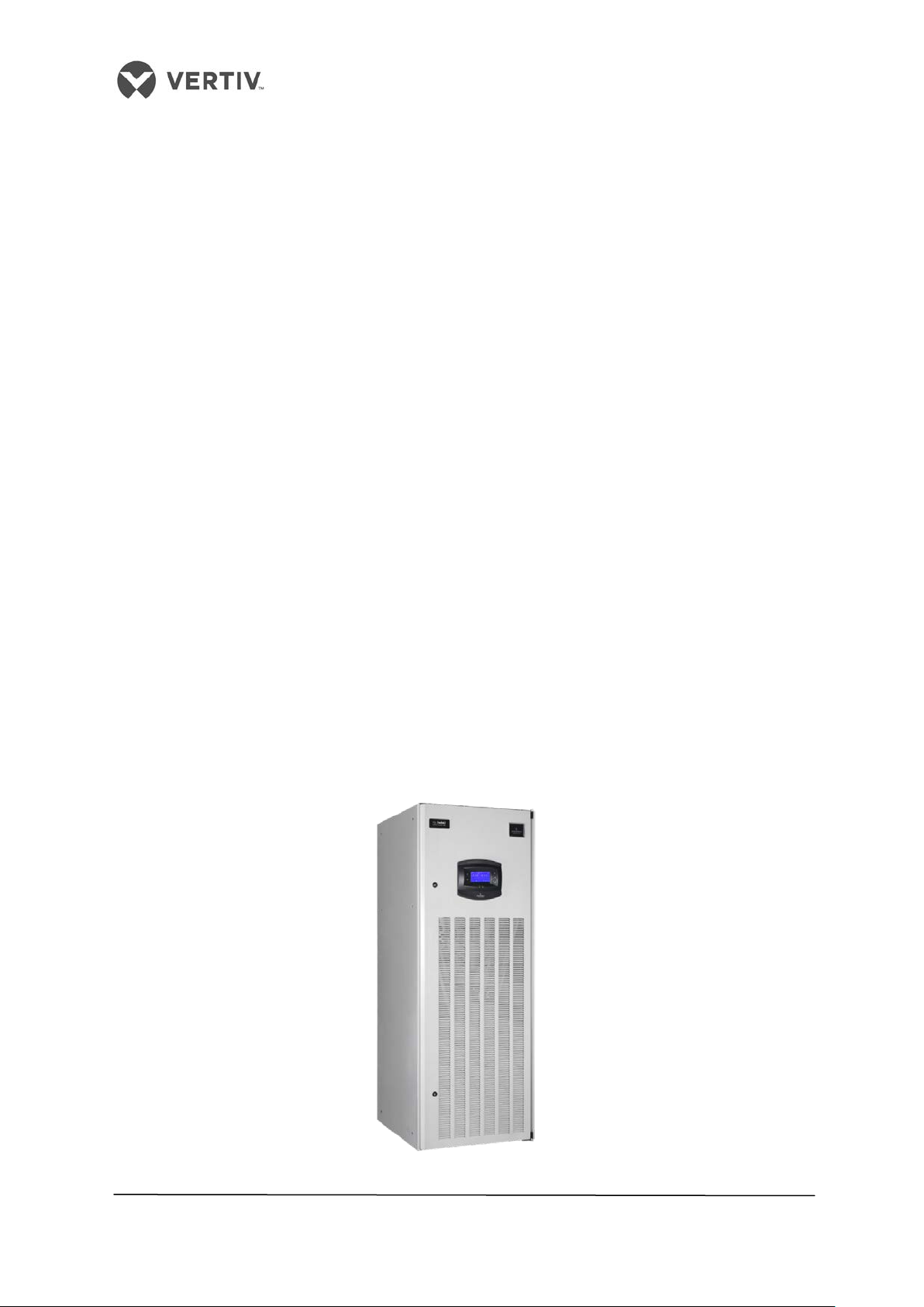
Figure 1-1 LPC Model
10
Page 11
Vertiv I Liebert LPC I User Manual
1.2 Model Description
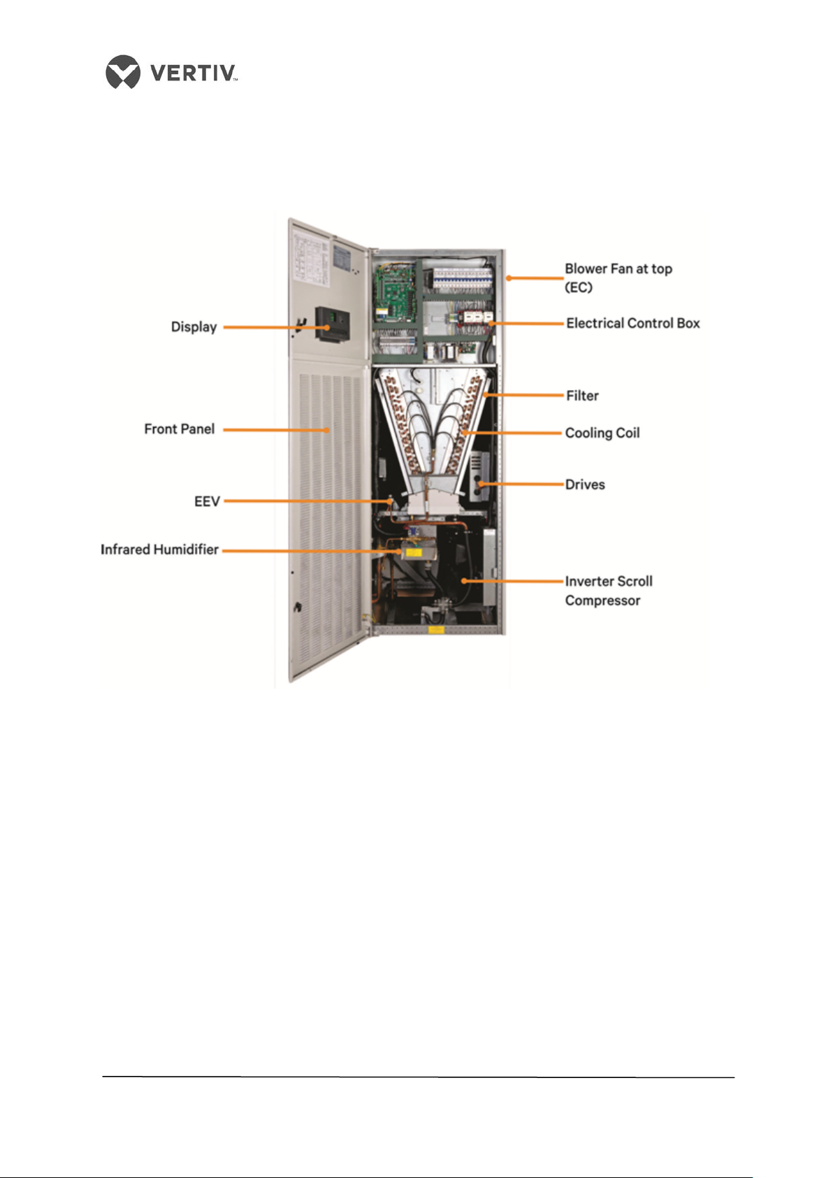
The following section depicts the Model Description and various components that are an
integral part of the air conditioner models in the Liebert LPC series. Further on, the working
conditions and technical specifications will be discussed in the later sections.
Figure 1-2 Main Components
11
Page 12

Vertiv I Liebert LPC I User Manual
Digit 2 Product Model
Digit 16 Enclosure options
Digit 3 Cooling Capacity kW
Digit 17 Mains Switch High Voltage Option
0-9 Nominal Net Cooling Capacity - kW
D
Main Non-Locking Disconnect
Digit 4 Cooling Capacity kW
Digit 18 Lock Out Low Voltage Option
0-9 Nominal Net Cooling Capacity - kW
0 None
Digit 20 Sensors
Digit 7 System Type
Digit 8 Airflow
Digit 21 Packaging
1 EC Plug FAN
P Standard Packaging
Digit 9 Power Supply
C Export Packaging
Digit 23 Order Identifier
Digit 11 Humidification
Digit 12 Display
L Large Display
Digit 13 Re-Heating
0 None
1.3 Model Nomenclature
The model of the LPC series AC is fully-defined by twenty-five digits, as shown in table 1.1.
Table 1.1
1
2
3
4
5
6
7
8
9
10
11
12
13
14
15
16
17
18
19
20
21
22
23
24
25
L 1 0 1 5 U A 1 3 8 H L 1 2 E 2 D 0 0 0 P A 0 0 0
Digit 1 Product Model
L
1 Number of Modules/Bays
Digit 5 Cooling Capacity kW
0-9 Nominal Net Cooling Capacity - kW
Digit 6 Air Discharge
U Upflow
A Air Cooled
N 380-415V / 3ph / 50Hz + N
Digit 10 Cooling System
8 R-410A EC Compressor
H Infrared Humidifier
C Color Display
Liebert LPC
Digit 15 Coil and Valves
E Standard DX Air cooled coil, EEV
2 Gray Orange Peel Grain Coating
Digit 19 Monitoring
0 RS485
S SIC Card
0
X Other Sensors
Digit 22 Special Requirements
A SFA - none
0
2
3
X
Digit 24 Order Identifier
None
Standard Static
High ESP 200 Pa
High Airflow/ESP other
SFA Included
1 SCR Heater Std. 1 Stage
2 SCR Heater Opt. 2 Stage
Digit 14 Air Filter
2 G4
3 F5
5 F7
L Air cooled-long piping>30m
X SFA Included
Digit 25 Order Identifier
0 None
B Back Air Return
D Bottom Air Return
X SFA Included
12
Page 13
Vertiv I Liebert LPC I User Manual
1.4 Components
This section gives an overview of the main components, optional components and features in
the LPC series of air conditioners.
1.4.1 Compressor
The DC Inverter Scroll compressor (with variable frequency) used in the Liebert LPC series.
The advanced compressor with a highly efficient motor and wide capacity regulation range is
designed to deliver maximum cooling with low noise and significantly less vibration. Its
expansive speed range and variable speed design imparts a new level of control for light load
efficiency and dehumidification. This compressor is tailored for higher efficiency and
reliability. With CoreSense technology baked-in, it continues to function effectively across a
wide range of conditions. Its robustness and technology safeguards it even while operating it
in adverse conditions.
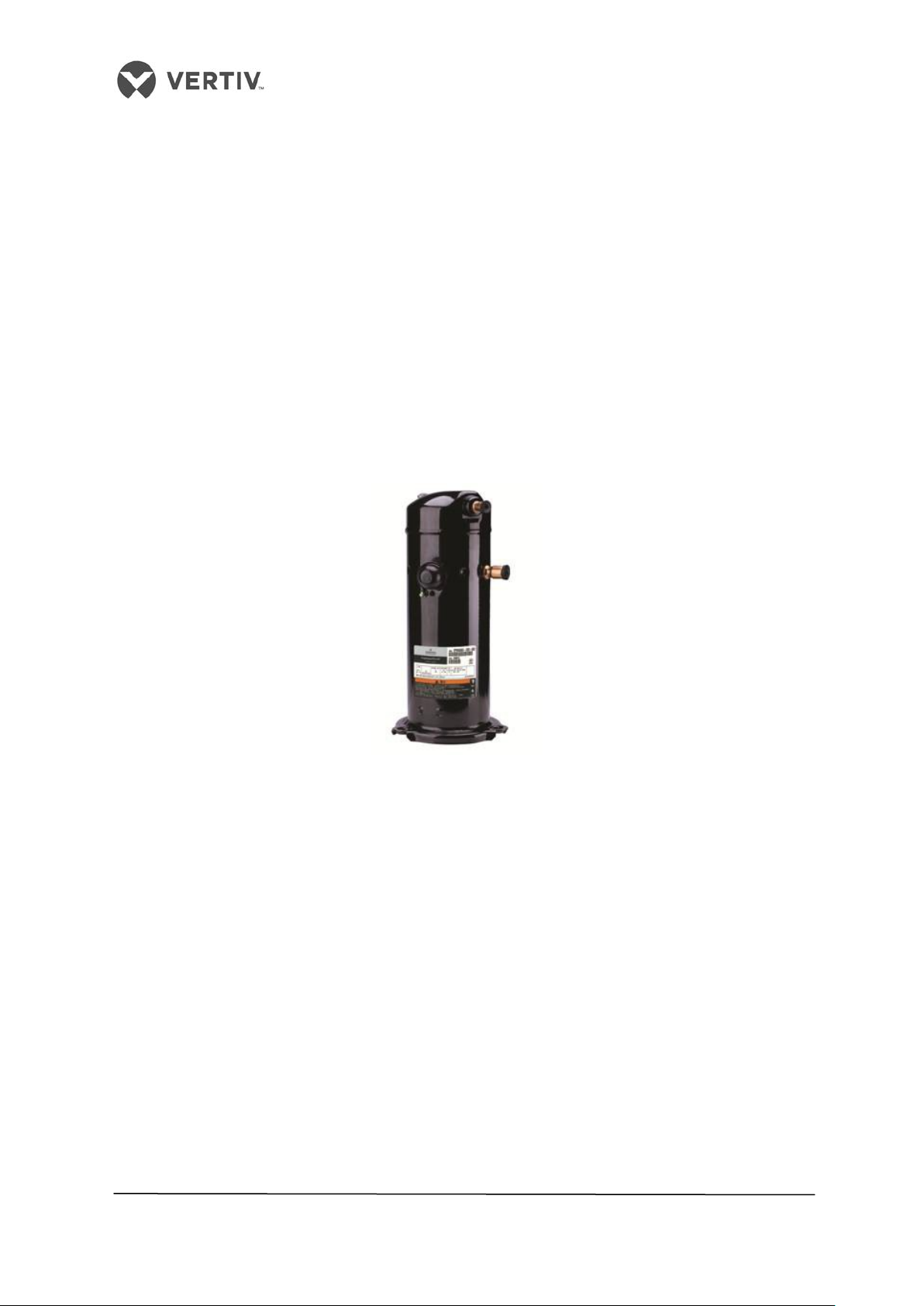
Figure 1-3 Inverter Scroll Compressor
1.4.2 Evaporator
Heat exchanger design and appropriate air distributions are crucial factors that determine
optimum performance. The Evaporator used in the Liebert LPC models consists of a fin-tube
heat exchanger for higher efficiency. The sophisticated design of the distributor ensures that
the refrigerant is distributed evenly in each loop, thereby improving the effectiveness of the
heat exchanger.
13
Page 14

Vertiv I Liebert LPC I User Manual
1.4.3 Electronic Expansion valve (EEV)
The EEV is designed for modulating control of the refrigerant mass flow with precision. The
EEV ensures effective control on super heating at the end of the evaporator and
simultaneously ensures that the compressor will never be filled by liquid from 10% to 100% of
its normal capacity.
Figure 1-4 shows the appearance of the EEV used in the Liebert LPC models:
Figure 1-4 Electronic Expansion Valve
1.4.4 EC Fans
The EC Fans used in the Liebert LPC models are energy-efficient and innovative with
integrated electronics and maintenance-free design. These fans provide a cost-effective way
to introduce energy-efficient technology by regulating the airflow and reducing fan input
power. Besides, the easy-to-connect facility bundled with the benefit of minimal wiring adds
to the high performance with a greater range of possible airflow rates.
Figure 1-5 shows the EC Fans used in the Liebert LPC model:
Figure 1-5 EC Fan
14
Page 15
Vertiv I Liebert LPC I User Manual
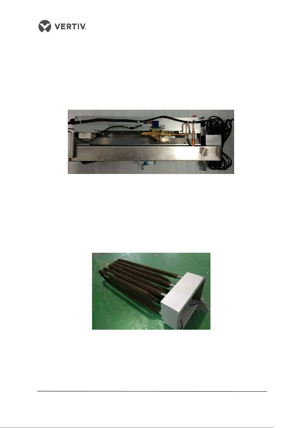
1.4.5 Infrared Humidifier
The infrared humidifier in the Liebert LPC series provides quicker and more responsive
operation which is quite important for mission-critical applications. The infrared humidifiers
use high intensity quartz over a stainless humidifier reservoir. These humidifiers reduce the
dependency of water quality and simultaneously achieve full capacity in quick time using
almost any water quality.
Figure 1-6 shows the basic functioning of an infrared humidifier:
Figure 1-6 Infrared Humidifier
1.4.6 Electric Heaters
The finned electric heaters used in the Liebert LPC series are highly reliable and
extremely productive. Stainless steel is the material used for manufacturing these heaters
with fin-tubular elements. The heaters perform at a quick pace and reduce the power
requirement during mission-critical workflow.
Figure 1-7 shows a sketch of a stainless steel electric heater:
Figure 1-7 Electric Heaters
15
Page 16

Vertiv I Liebert LPC I User Manual
1.4.7 Filter-driers
Moisture can have an adverse effect on the operation and life of a system in the refrigeration
cycle. To counter that effect, Filter-driers are used to filter out particles, and remove and hold
moisture to prevent it from circulating through the system.
1.4.8 Controller
The Controller adheres to the latest and highly advanced PID regulation technology. With
features, such as the baked-in ability to recover from a power failure and streamlined
usability, it has a simplistic user interface making it easy-to-operate. Power-packed with
fuzzy logic, it is an intelligent utility with dimensions of 128x64 (dot matrix) with frontal
displays and high voltage protection features. The operation time of the main components is
available through the menus. Configured with the RS485 port in compliance with the
communication protocol of Ministry of Information Enterprise, it ensures top reliability and
maximum efficiency.
An interesting development is the compatibility with Vertiv Co.’s remote monitoring-and-
management application. SiteWeb (the remote management application) gathers a
continuous stream of data related to vital health parameters such as DC Power, batteries,
and renewable power sources to name a few.
Figure 1-8 shows the appearance of the controller currently used in the Liebert Models:
Figure 1-8 Controller
16
Page 17
Vertiv I Liebert LPC I User Manual
Ambient temperature
L1015
1.4.9 Liquid Indicator
The liquid indicator works as a toolset used for observing the refrigerant state, specifically
the moisture content of the system. When the moisture content exceeds the standard or a
particular limit, the color will be changed indicating the irregularities in the moisture content.
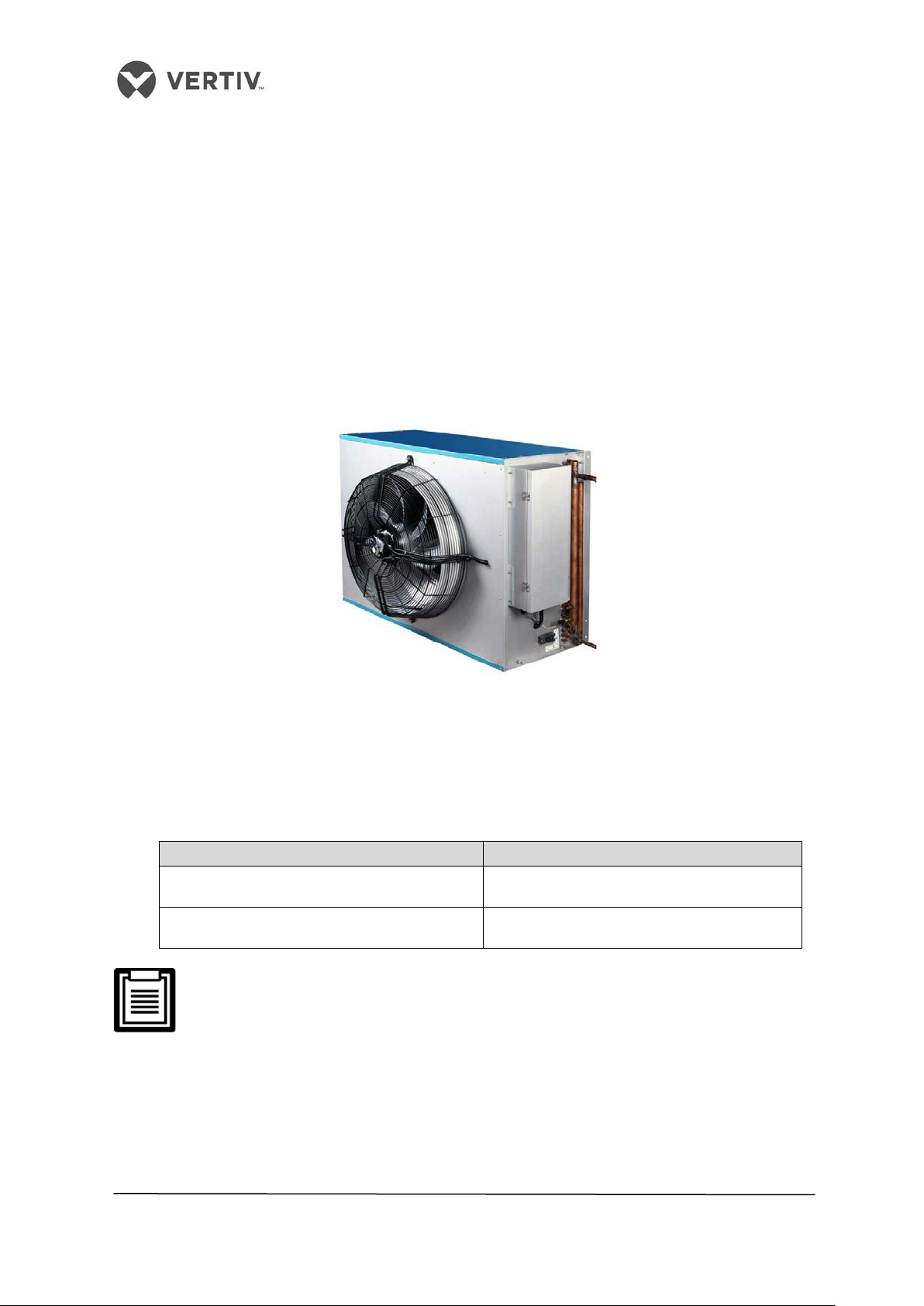
1.4.10 Condenser
The Liebert range of Air Cooled Condensers offer unique benefits including sharp design,
antirust aluminum cabinets, low sound levels, and reliable operation over a wide range of
ambient conditions.
Figure 1-9 shows a pictorial depiction of the Condenser:
Figure 1-9 Condenser
Condenser sizing parameter
Sizing of the condenser is based on the ambient temperature as mentioned in the
Table 2.1.
Table 2.1
≤ 40 ℃ LSF24-R3
> 40 ℃ LSF32-R3
For more information on the condenser, refer to the separate condenser manual
which explains the entire condenser ecosystem in detail.
17
Page 18
Vertiv I Liebert LPC I User Manual
1.5 Optional Components
The Liebert LPC range of air conditioners has optional components that can be a part of the
overall configuration. These include two-stage electric heating, plenum, multiple temperature
and humidity sensors, and Air filters
1.5.1 Two stage electric heating
In Liebert LPC, a two-stage electric heater can be used for enhanced heating as per the user
requirements.
1.5.2 Plenum
According to the user requirements, the unit will be configured with a plenum as per the
dimensions mentioned in section 2.6.1 Plenum Dimensions). For a custom plenum, please
contact Vertiv Co. for the solution.
1.5.3 Multiple Temperature and Humidity sensors
As per the user requirements, there is a facility of using up to 5 sensors. Refer to the Remote
Temperature and humidity sensor placement section in Chapter 6 (Refer 6 - Appendix)
1.5.4 Air Filter
According to the user requirements, different kinds of filters based on their classification
standards such as F5 and F7 can be provided for different levels of filtering.
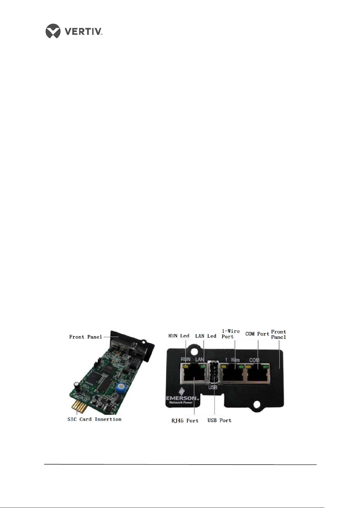
1.5.5 SIC card
SIC card with #77, #78 control panel is equipped with RS485 interface which is a standard
protocol for the MODBUS. RDU-SIC can be equipped with monitoring cards, as shown in
figure 1-10. The RJ45 interface is provided for customer access via USB port.
Figure 1-10
18
Page 19
Vertiv I Liebert LPC I User Manual
Item
Requirements
-25° C ~ + 55° C
Total transportation and storage time should not
<1000m. If the altitude is above 1000m, then Derating will
occur. Please contact Vertiv™ for this resolution
1.6 Operating Parameters
In this section, the environmental conditions will be discussed, which includes the Operating
and Storage environment:
1.6.1 Storage Environment
The table 1.2 defines the various storage aspects and requirements, which also includes the
Ambient Humidity, Ambient temperature, and Storage time conditions.
Table 1.2
General Requirements Indoor, clean and without dust
Ambient Humidity < 95% RH
Ambient Temperature
Storage Time
exceed six months. Otherwise, the performance needs
to be re-calibrated
1.6.2 Operating Environment
The table 1.3 defines the various requirements and aspects of the Operating environment,
including the Ambient Temperature, Protection Level, Attitude, and the voltage range.
Table 1.3
Item Requirements
Indoor 18° C ~ 35° C
Ambient Temperature
Outdoor
Protection Level IP20
Altitude
Operating Voltage range
380~415 (-10%~+6%)V,3N~50/60Hz
-15° C ~ +45°C, if low temperature kit is used, the
lowest outdoor operating temperature is -34°C.
19
Page 20

Vertiv I Liebert LPC I User Manual
PART II
INSTALLATION
20
Page 21
Vertiv I Liebert LPC I User Manual
2 Installation
The Installation process consists of the following procedures, namely -
• Pre-installation
• Installation Preparation
• Mechanical Installation
• Electrical Installation
2.1 Pre-installation
Pre-installation contains the following 3 sub sections, namely -
• Transportation & Movement
• Unpacking
• Inspection
2.1.1 Transportation and Movement
When it comes to transporting the system, Railroad is the most preferable choice. However, if
railroad transportation is not possible, then the truck transport option is an optimal choice.
One precaution is to choose roads that do not have too many bumps and if any, avoid it as
much as possible.
Liebert LPC series of air conditions are on the heavier side and therefore, it is recommended
that equipment such as an electric forklift is utilized for these heavy-duty systems. Move the
equipment to a location which is in the vicinity of the installation site. If an electric forklift is
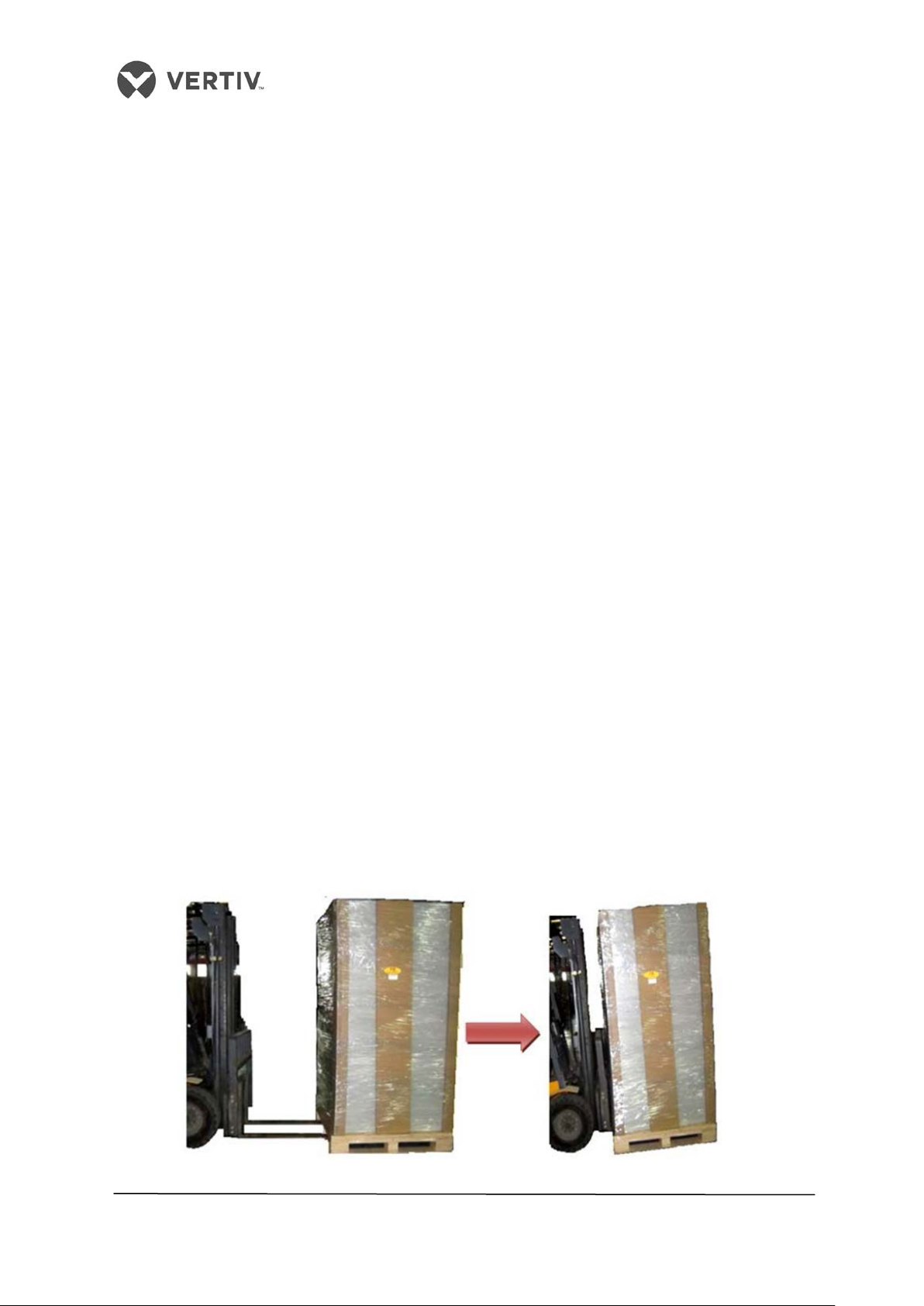
used, insert the tines of the forklift below the pallet as displayed in Figure 2-1. Align the tines
with the centre of gravity to prevent the equipment from falling over.
Figure 2-1 depicts the way the tines of the forklift are inserted below the pallet and in the
same image, the graphic to the right indicates that the tines are aligned with the center of
gravity to prevent the equipment from falling over:
Figure 2-1 Electric Forklift handling a Liebert LPC system
21
Page 22
Vertiv I Liebert LPC I User Manual
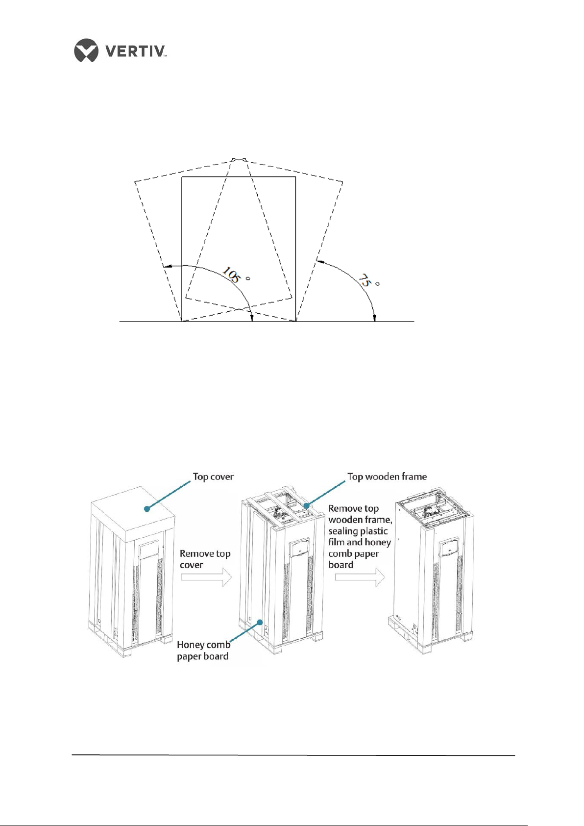
In Figure 2-2, the air conditioner is lifted using the forklift truck and is aligned with the center
of gravity. While moving the indoor unit, the obliquity needs to be maintained within an angle
inclination of 75° to 105°.
Refer to Figure 2-2 to understand the concept better:
Figure 2-2 Handling Inclination
2.1.2 Unpacking for Paper Packaging
Once the equipment is closest to the final installation site, unpack the system. Following are
the important steps to be implemented in the hierarchy mentioned in the following list for
unpacking:
• Remove the top cover and tangled stretch film before removing the honeycomb
board as shown in Figure 2-3:
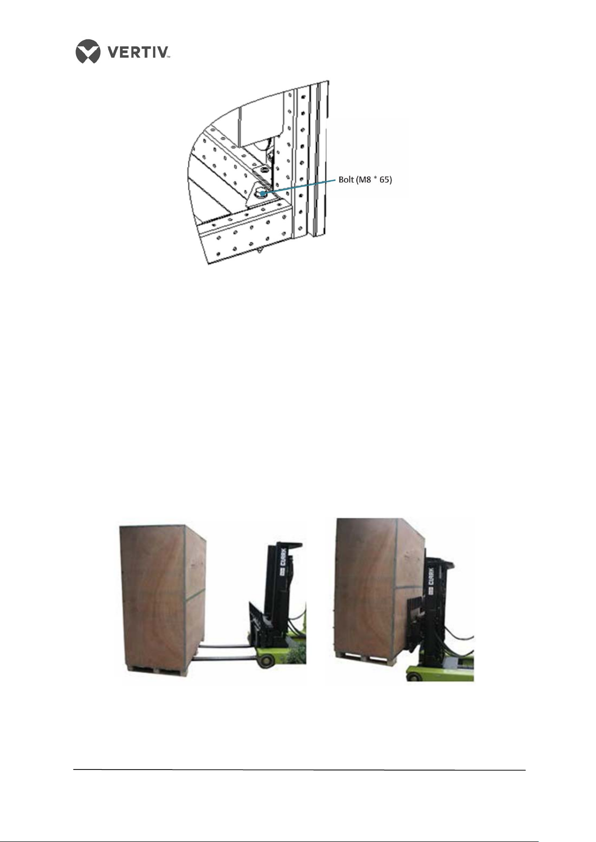
• The unit is fixed on a base pallet with M8 * 65 bolts. Use a 14mm wrench to remove
those bolts. Figure 2-4 shows the unit fixed on the base pallet using the M8 * 65
bolts.
Figure 2-3 Unpacking the system
22
Page 23
Vertiv I Liebert LPC I User Manual
Figure 2-4 Fixing bolt on the base pallet
2.1.3 Unpacking for Wooden Packaging
If a wooden packaging is used instead of paper packaging, the process is slightly different.
The following process Is to be adhered if a wooden packaging is used. For export, a wooden
packaging is used and the process is slightly different from the process followed in section
2.12.
The Transportation mode is preferably via Railroad or shipping; however, there are times
when truck transportation is mandatory for some locations. In such cases, chose roads that
are not bumpy to ascertain that there is no damage to the equipment. It is highly
recommended that an electric forklift is used to unload and move the product enclosed in
the wooden packaging.
Refer to the Figure 2-5 to understand the process better:
Figure 2-5 Transportation for export Wooden-packaged LPC systems
In Figure 2-5, the tines of the forklift are inserted below the pallet. This is done to ensure
that the equipment does not fall over leading to injury to the personnel or damage to the
equipment.
23
Page 24

Vertiv I Liebert LPC I User Manual
Similar to the Unpacking explained in the section 2.1.2 in the manual, the obliquity needs to
be maintained with an angle inclination of 75% TO 105%.
Figure 2-6 Moving obliquity
•
Upon arrival of the unit, prior to unpacking, verify that the labeled matches
the bill of lading. Inspect and check all items for damage, either visible or
concealed.
•
Damage should be immediately reported to the carrier. A damage claim
needs to be filled and a copy of the same must be sent to Vertiv Co. or the
authorized sales representative.
2.1.4 Removal of external package
The chilled water version uses the international packaging.
Following are the procedures that need to be adhered to strictly for removing the external
package:
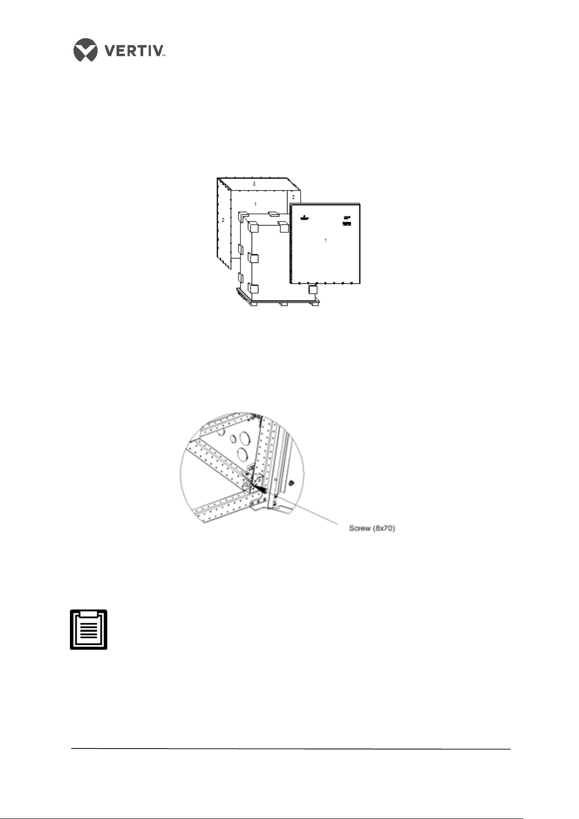
1) Use a hammer or straight screwdriver to straighten the hook as displayed in Figure 2-
7 to view the procedure:
Figure 2-7 Straightening the hook
24
Page 25
Vertiv I Liebert LPC I User Manual
2) Initially, straighten all the hooks fixed with side board 1. Once the hooks are
straightened, removed the sideboard 1.
3) Follow the same procedure with sideboard 2.
4) On straightening all the hooks and removing sideboard 2, remove the top cover 3.
Figure 2-8 shows the process of removing the Sideboards and the top cover:
Figure 2-8 Removing the Side boards and Top cover
5) The unit is fixed to the base pallet with an 8*70 screw.
The unit is fixed to the base pallet with an 8*70 screw. Figure 2-9 depicts the positions of the
wooden screws.
Figure 2-9 Positions of the wooden screws
A 17mm open-end spanner, ratchet spanner, or sleeve can be used to remove the fixing
screws.
The plastic bags should not be damaged during the unpacking process for dust
protection on the AC unit as per the requirement.
2.1.5 Inspection
Moving forward, check the system fittings and its components against the packing list to
ensure that everything is in place and the assembly is intact. If any parts are missing or
damaged, immediately report to the carrier about the same. If hidden damages are observed,
then contact the local offices of that carrier as well as Vertiv Co. at the earliest.
25
Page 26

Vertiv I Liebert LPC I User Manual
2.2 Installation Preparation
The Liebert LPC range of air conditioners is streamlined for maintaining a favorable and
suitable environment for testing laboratories and similar testing ecosystems. Strict
adherence to the installation procedures is mandatory for appropriate installation of the
Liebert LPC air conditioners. In the previous section, we looked at the working conditions
which included the operating, storage, and technical specifications for the Liebert LPC
models. In this section, let’s look at the installation preparation before moving on to installing
the LPC system to simulate a real-time scenario.
2.2.1 Equipment Room Requirement
The equipment room must be prepared to ensure a smooth operation flow and obtain
accurate results. The equipment room must meet the standards for appropriate ventilation
and heating. The design specifications for the air conditioners must be apt and should
match the energy- efficient design standards.
Following are the requirements for maintaining a favorable room environment prior to
installation:
• The room should have suitable and effective heat insulation.
• The equipment room should have a sealed damp-proof layer. Polyethylene film should
be used for the damp proof layer of the ceiling and walls. Alternatively, moisture-proof
paint can be used to simulate the same effect akin to Polyethylene. Care should be taken
that the coating on the concrete wall and floor must be damp-proof.
• Outdoor air increases the load of heating, cooling, humidification, and dehumidification
significantly. Therefore, all the doors and windows must be closed. Gaps and seams must
be highly narrow to prevent the outdoor air from entering the equipment room. It is an
industry- best practice to keep the inhalation of the outdoor air below 5% of the total
indoor airflow. Take appropriate thermal insulation and antifreeze measures for outdoor
water pipes to avoid poor drainage and insufficient water supply caused by freezing.
Vertiv recommends that the site preparation is defined as per the requirements.
However, if these requirements are not met, Vertiv recommends that
rectifications be made on the site so that it complies with the specified
requirements and conditions. However, if the rectifications or modifications are
not implemented, then Vertiv does not guarantee the accuracy and precision of
the temperature and humidity provided by the LPC model.
2.2.2 Installation Space requirements
Air conditioners in the Liebert LPC range are advanced precision air conditioners and the
recommended way is to install them as standalone equipment.
• For servicing, repairs, and maintenance, it is imperative that adequate maintenance
26
Page 27
Vertiv I Liebert LPC I User Manual
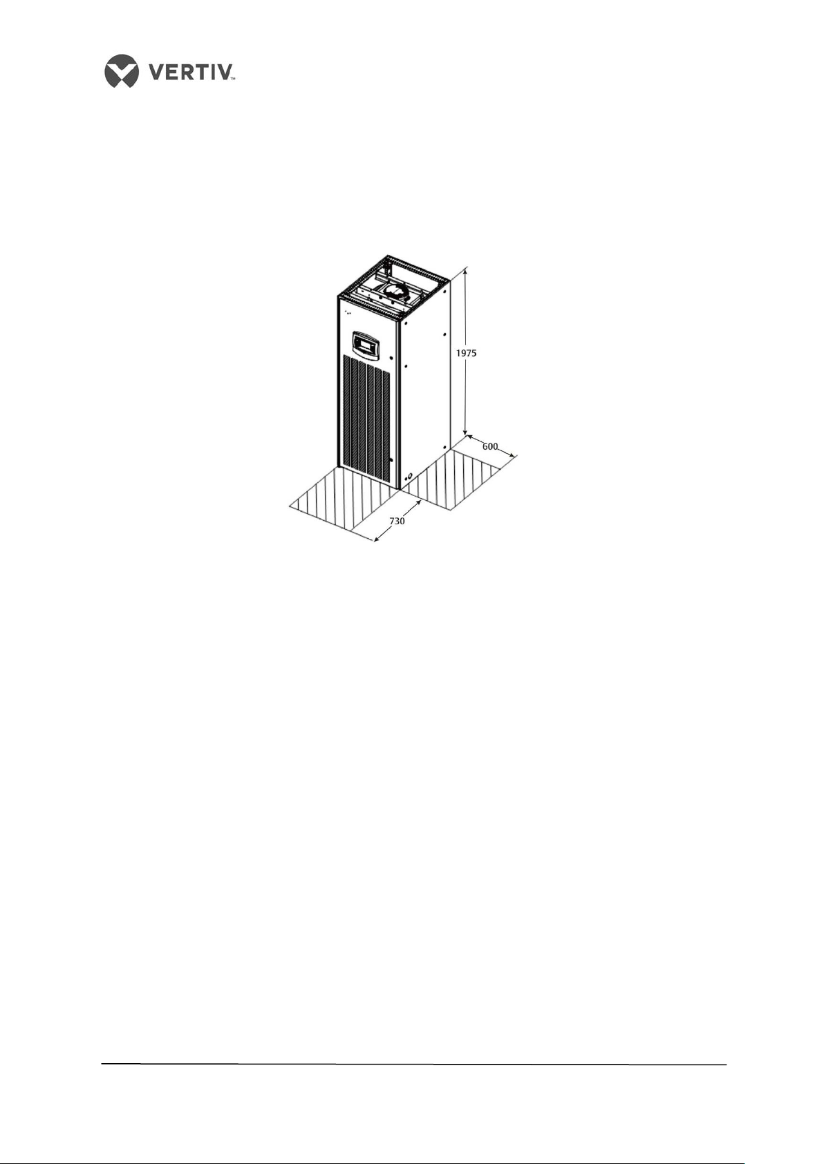
space is allocated at the front as well as the right side of the equipment. Allocate a
minimum space of 730mm for maintenance purposes in front of the system. Next,
allocate a minimum space of 600mm for maintenance on the side (right-side) of the
equipment. This allocated space is to facilitate the regular maintenance tasks such as
filter replacement, or servicing or repairs to the blower or humidifier among others.
Figure 2-10 shows an illustration of the maintenance space to be allocated:
Figure 2-10 Liebert LPC Maintenance space
2.3 Mechanical Installation
The following points discuss some aspects that are taken into consideration during the
mechanical installation process:
• Prior to installation, ensure that the installation preparations have been read and
implemented. Check if any changes are to be made to the plumbing, wiring, or
ventilation facility prior to mounting the equipment. Once the installation preparations
have been taken into consideration, then we move on to the next step in the installation
process where we need to setup the system.
• The LPC has an indoor as well as an outdoor unit. The Indoor unit comprises of all
components excluding the Condenser. The Condenser is the part of the Outdoor unit.
The indoor unit must be installed in the application room or a separate room as per the
protocols followed in the application laboratory. The outdoor unit must be installed
outdoors or on ventilation space on the ground or other floors as per the building
architecture.
• Industry-wide standards are followed for the selection, layout, and fixing of pipes.
• Several factors such as pressure drop, compressor oil return, noise reduction, and
vibration are considered during the design and installation process.
• The units shall be fixed by screws and mounting rails to avoid vibrations during the start-
up or operating processes.
27
Page 28
Vertiv I Liebert LPC I User Manual
2.4 System arrangement during installation
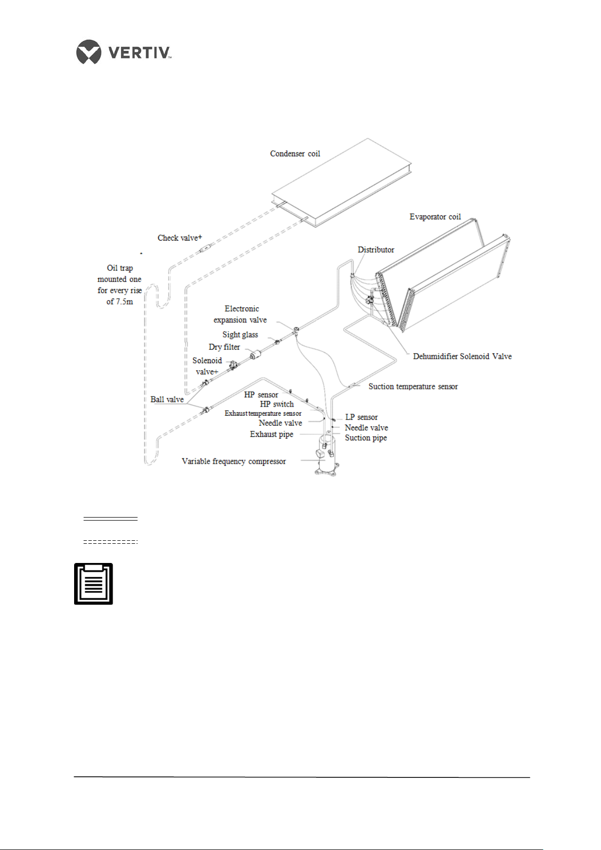
The overall structure and arrangement of a Liebert LPC air conditioner is depicted in Figure
2-11.
Figure 2-11 Overall Layout diagram
• : Factory piping
• : Field piping (by technical personnel)
The following points should be taken into consideration before checking out
the overall layout diagram:
• The single system is used as an example to describe the entire system.
• Vertiv staff and qualified professionals lay out the piping in the laboratory.
• Piping is done by technicians.
• Components (marked with *) are not supplied by Vertiv Co. but are
recommended for proper circuit operation and maintenance.
• Additional components (marked with +) are required when the equivalent
length exceeds 30m.
28
Page 29
Vertiv I Liebert LPC I User Manual
2.5 System Installation
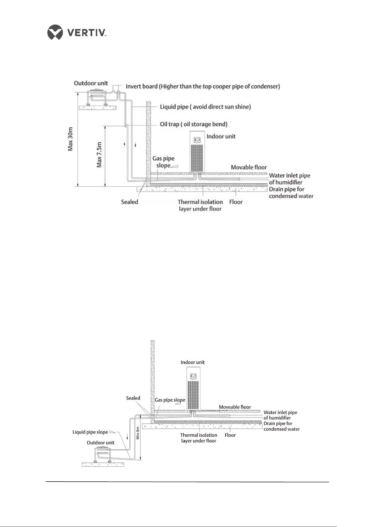
The system installation schema is defined in Figure 2-12:
Figure 2-12 The Condenser is higher than the Compressor during installation
• The Condenser is installed higher than the Compressor. Therefore, an inverted back
bend is fitted to the discharge line and liquid line of the condenser. This modification
is important as it helps prevent the liquid refrigerant from flowing back once the
condenser stops. Remember that the top-end of the inverter back-bend must be
installed higher than the ultimate level of the copper pipe of the condenser.
• However, if the condenser is installed lower than the compressor, no modification is
needed as it fits the bill perfectly.
• Figure 2-13 depicts the schema of system installation when the condenser is
installed at a lower level than the compressor:
Figure 2-13 The Condenser is lower than the Compressor during installation
29
Page 30

Vertiv I Liebert LPC I User Manual
2.6 Product Dimensions
The dimensions of the indoor unit are displayed in Figure 2-14:
Figure 2-14 Dimensions of the Indoor unit
Specifications are shown in the table displayed in table 2.1
Dimensions and Weight of the Indoor unit
Table 2.1
Models Model Dimensions(mm) Net Weight (Kg)
L1015 730x845x1975 (WxDxH) 280
2.6.1 Plenum Dimensions
The Plenum is an assembly of all the components in the unit. The following table 2.2 displays
the dimensions of a plenum:
Table 2.2
Type Depth (mm) Width (mm) Height (mm)
L1015 850 (D) 730 (W) 400 (600 optional) (H)
30
Page 31
Vertiv I Liebert LPC I User Manual
Contact Vertiv Co. for non-standard production queries if the height of the platform
selected for an air conditioning unit exceeds 600mm.
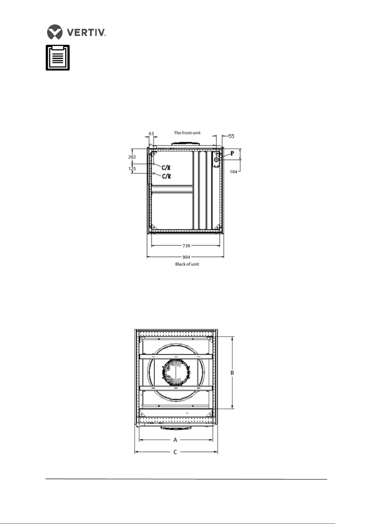
2.6.2 Base pallet cut-out location dimensions
Following is a schematic diagram that depicts the cut-out location and dimensions of the
base pallet. The coil outlet is visible after removing the side panel from the base pallet.
Figure 2-15 shows the dimensions and position of the coil outlet:
Figure 2-15 Base Pallet cut- out Location dimensions
2.6.3 Positions & Dimensions of the Top-cover
The positions and dimensions of the air outlet on the top cover of the unit are depicted in
Figure 2-16 and Table 2.3.
Figure 2-16 Position of the air outlet on the top cover of the unit
31
Page 32
Vertiv I Liebert LPC I User Manual
Table 2.3
L1015
650
630
730
Models A B C
2.6.4 Side panel Knock-out locations
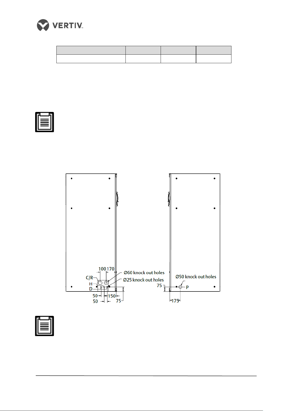
If there is difficulty in the piping and wiring process from the base, then an alternative option
would be a connection from the side panel. The locations and dimensions of the knock-out
holes are depicted in Figure 2-17.
The outlet and inlet holes should be selected based on the actual needs.
Remember the rule that only one service is used per opening.
P Power Cable Inlet/Outl
et | C/R Cooling water/ Refrigerant inlet and outlet pipe holes
H Hole for incoming water pipe of the humidifier
D Hole for Drain pipe
The equipment has knock-outs, be sure to mount the sleeve to the cable holes
to avoid cutting the cables.
Figure 2-17 Side panel Knockout connection
32
Page 33
Vertiv I Liebert LPC I User Manual
2.7 Installation of the Indoor unit
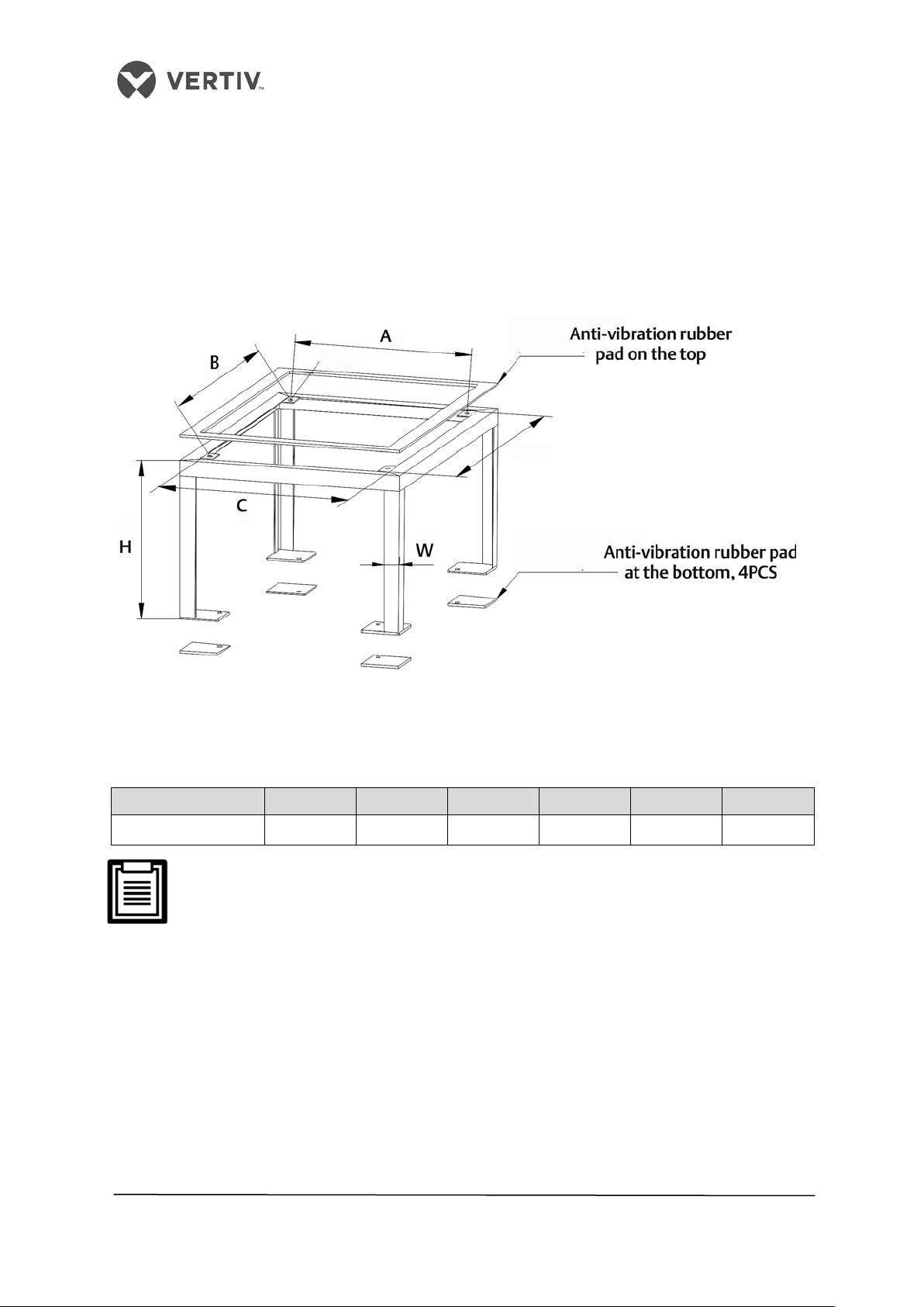
The base shall be created by the installation team according to the dimensions, weight, and
height of the units to ensure that structural stability and rigidity meets the requirement. The
base can be created by the users; alternatively, Vertiv Co. can be asked to create it too.
Figure 2-18 depicts a schematic diagram of the production base along with the specific
dimensions.
Figure 2-18 Appearance and dimensions of base (unit: mm)
Refer to the table 2.4 to view the base dimensions for the LPC models:
Table 2.4
Models A B C D H W
L1015U 610 710 650 750 350<H<550 40
Remember that the external side boards of the unit cannot bear the weight.
Next, install the stand and the indoor unit cabinet apart from adding a rubber cushion as
explained in the following steps:
2.7.1 Installing the base
• Determine the installation position in accordance with the requirements discussed in
the Installation Space requirements discussed earlier in the Installation Preparations
chapter
• Fix the base on the selected mounting position
• Fix the base to the ground using expansion bolts or spot welding
33
Page 34

Vertiv I Liebert LPC I User Manual
Lateral
Thickness: 2mm to 3mm
• Re-calibrate the base using a horizontal ruler before fixing it to ensure that the top
surface of the base is leveled.
2.7.2 Vibration absorption
• Add a layer of rubber cushion to the top, side (lateral), and bottom of the steel plate
to avoid the transmission of the vibration during the operation of the unit.
Table 2.5 shows the dimensions of the rubber cushion that is used to absorb the vibration:
Table 2.5
Item Position Specification
Top Thickness: 3mm to 5mm
Rubber Cushion
Bottom Thickness: 10mm to 12mm
2.7.3 Installation of the indoor unit cabinet
• Install the indoor unit on a base horizontal plane.
• Post installation, maintain the unit in the same horizontal plane.
There is no need to perform welding or fix other rigid connections between the
base and indoor unit.
2.8 Installing the Condenser
Refer the Condenser manual for detailed information on Condenser Installation.
2.9 Piping for the unit
There are four types of pipes that are to be installed in the unit, namely –
• Condensate drain pipe of the indoor unit
• Water inlet pipe of the humidifier
• Copper pipes between the indoor unit and condenser
• Extension kit (optional)
Depending on the conditions for selecting the kit, the users shall decide whether there is a
need for the extension kit while installing the pipes.
All the joints of the cooling pipes must be silver-brazed.
34
Page 35
Vertiv I Liebert LPC I User Manual
2.9.1 Connecting the condensate drain pipe of the indoor unit
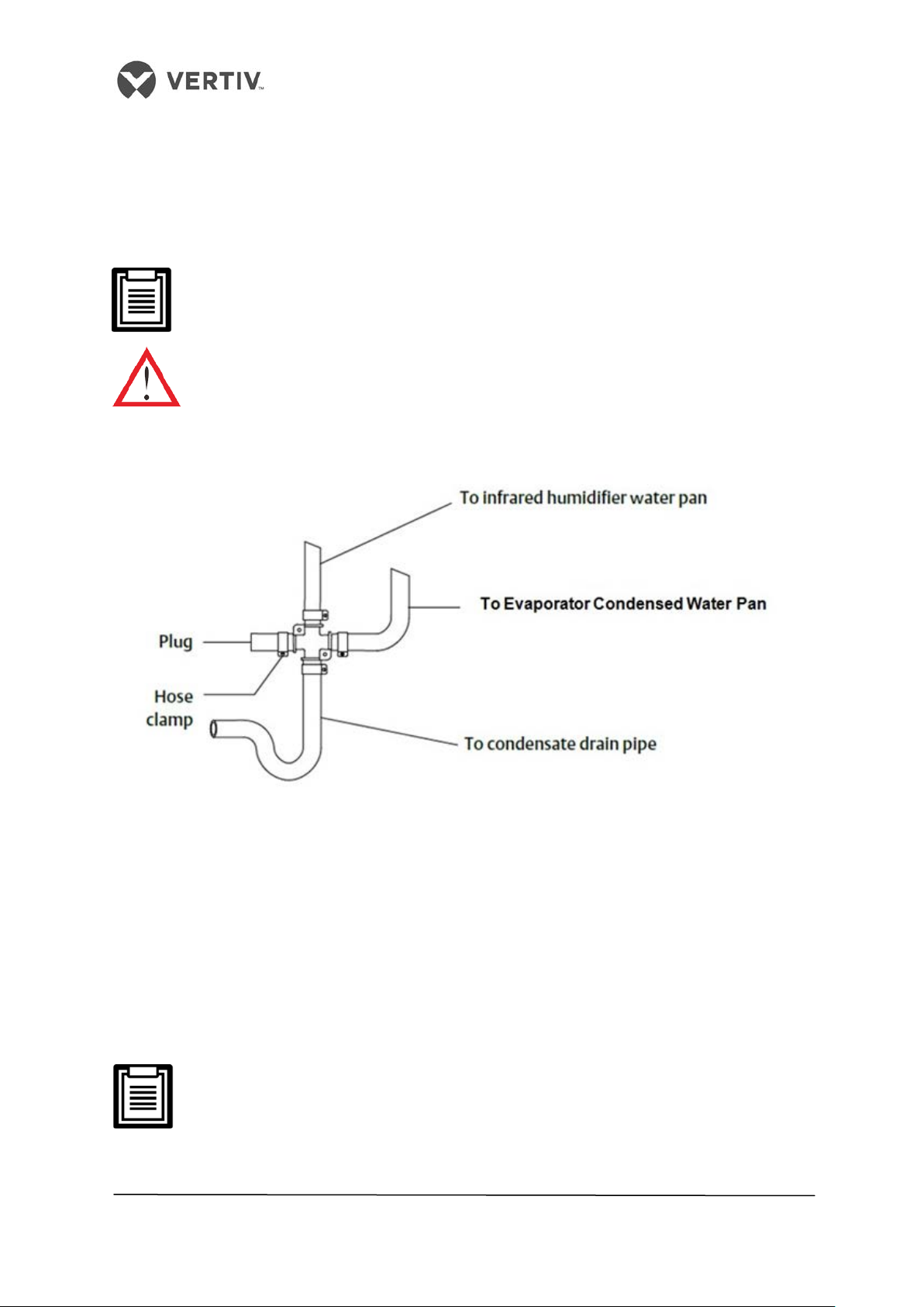
The condensate of the infrared humidifier and evaporator converge at a cross-connector
following which it is emptied using a drain pipe as reflected in Figure 2-19. The Outer
diameter of the pipe is 25mm. However, if the drain pipe is used by 3 or more units, the
minimal outer diameter of the pipe should be 40mm.
While connecting the drain pipe, ensure that the U bend is installed vertically and
the U shape is not distorted so that the condensate can be drained quickly in an
effective manner.
The water pipe must be resistant to heat above 90° C because the infrared
humidifier contains flowing hot water.
Refer to Figure 2-19 which depicts the connection of the drain pipe for condensate water.
Figure 2-19 Connection of drain pipe for condensate water
2.9.2 Connecting the water inlet pipe of the infrared humidifier
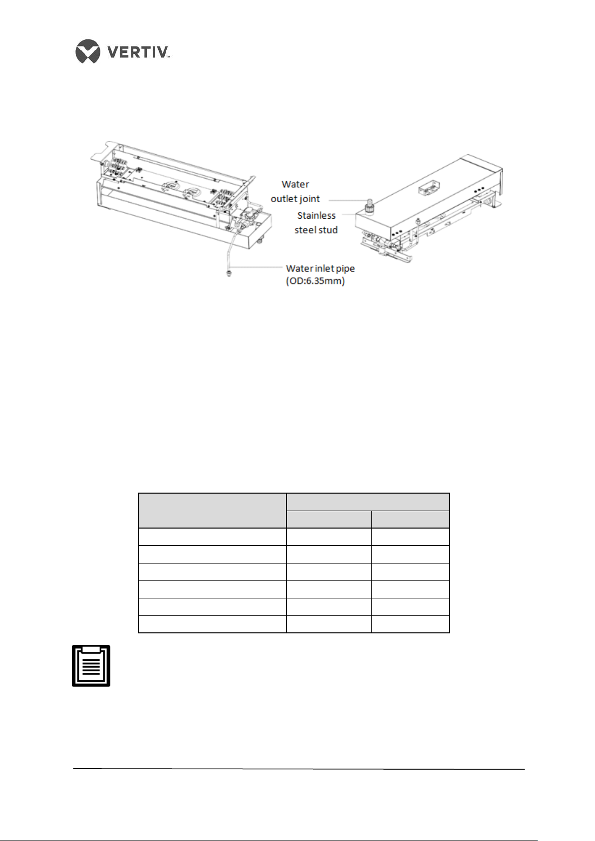
An isolation valve should be fitted to the water inlet pipe to facilitate maintenance. The
connection of the water inlet pipe must be sealed to prevent potential leakage. The infrared
humidifier has a copper pipe with an outer diameter of 6.35mm. There is a ¼” copper nut at
the end of the copper pipe to which we have connected the ¼” * ½” conversion copper thread
connector to avoid losing them.
• When the main pipe pressure rises over 700Kpa, a pressure reducer should
be fitted as ideally, the main pipe pressure should be in the range of
100Kpa-700Kpa.
• Also, when the main pipe pressure falls below 100Kpa, a water tank and
pump system must be used.
35
Page 36
Vertiv I Liebert LPC I User Manual
10m
16
12.7
20m
19
12.7
30m
19
16
40m*
22
16
50m*
22
16
60m*
22
16
• Some products may incorporate components due to local regulations.
Figure 2-20 depicts the connection of the water inlet pipe of the infrared humidifier:
Figure 2-20 Connection of the water pipe of the infrared humidifier
2.9.3 Connecting copper pipes (discharge & liquid) between the indoor unit &
condenser
• The pipe diameter is related to the system pressure drop and therefore, the pipe
diameter of the indoor unit and outdoor unit should be determined according to
specifications listed in the following table (Refer Table 2.6).
• Alternatively, contact the technicians and engineers at Vertiv’s local office for the
connection.
Table 2.6
Pipe Length
D L
L1015
• * denotes extension kit to be added.
• D - Discharge Line L - Liquid Line
• Consult Vertiv Co. if the line length exceeds 60m
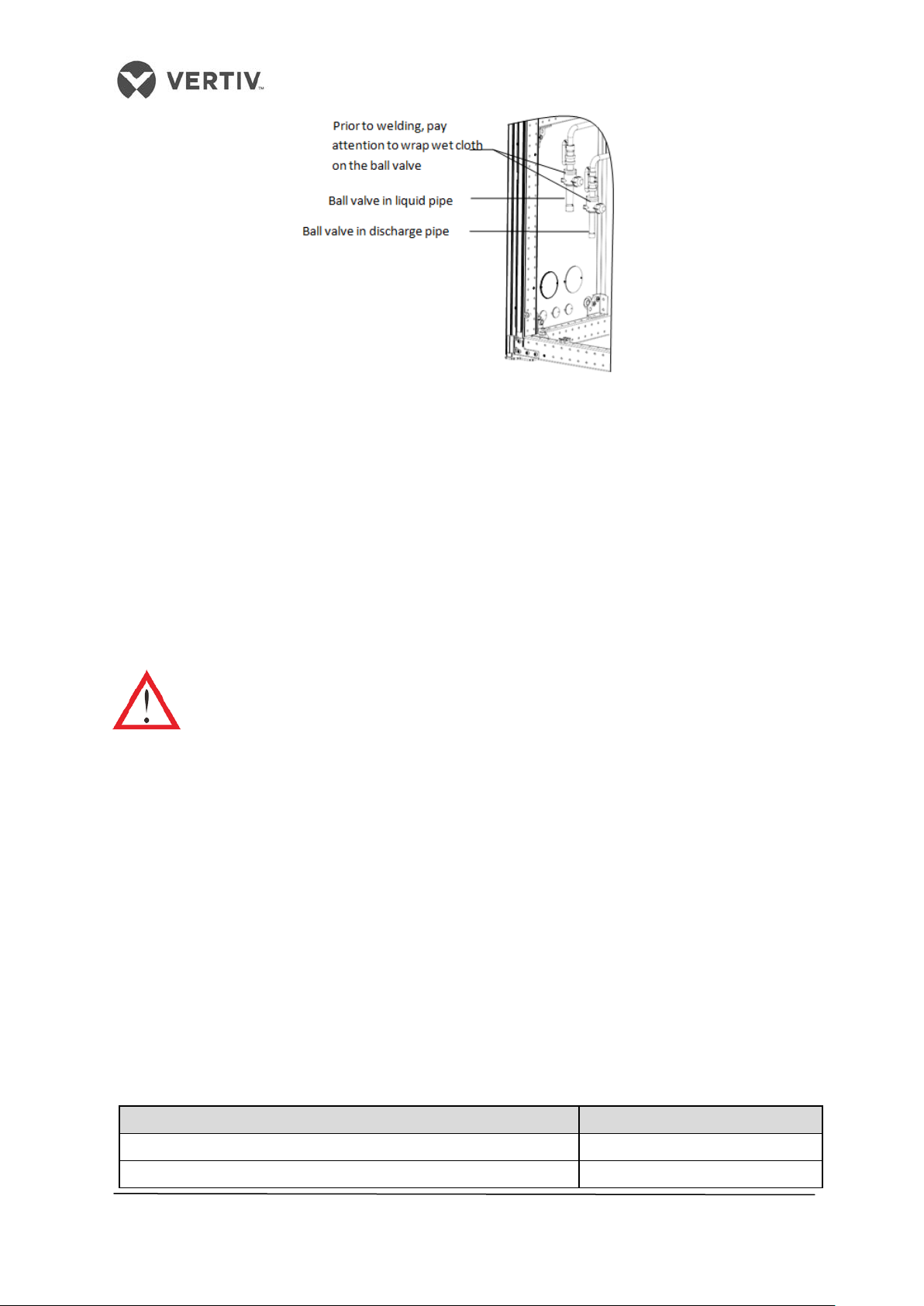
• Use welding to connect the 2 copper pipes. The connection ball valves of the inlet
and liquid pipe of the indoor unit are displayed in Figure 2-21.
36
Page 37
Vertiv I Liebert LPC I User Manual
Figure 2-21 Connecting the ball valves of the discharge and liquid pipe of the indoor unit
Notes, Warning, and Instruction labels are pasted on the base and side panel close to the ball
valve.
• Wrap the ball valves with a wet cloth before welding to prevent the label from getting
burned during the welding operation.
• Connect the discharge pipe and liquid pipe of the indoor unit according to the
instructions laid down in the label.
• Horizontal sections of the discharge pipe should be tilted downwards with a slope of
at least 1:200 (5mm down for each 1m run). The discharged pipes should be
insulated in the conditioned space (including under a raised floor).
The system piping should not be exposed for more than 15 minutes. Longer
period of exposure may lead to the compressor refrigeration oil being
adversely affected by moisture, which can be detrimental to the life of the key
components and stability of the system.
2.9.4 Installing the pipe extension kit
• If the length of the one-way pipe exceeds 30m or the vertical distance between the
indoor unit and outdoor unit exceeds the values in the table 2.7, consult Vertiv Co. for
the installation.
• The recommended pipe sizes are equivalent lengths that consider the resistance of
the bends.
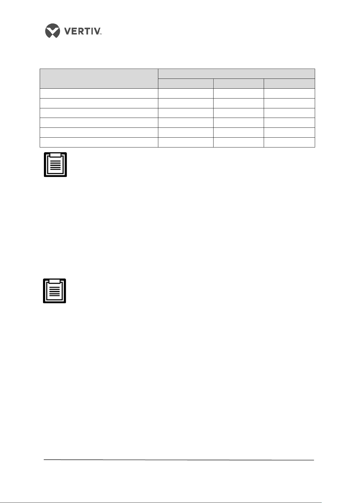
The table 3.7 shows the equivalent length for partial components, and before installation, the
sizes mentioned in the table must be taken into account and checked keeping in mind the
site conditions.
Table 2.7
• Vertical distance between the Indoor and Outdoor unit
Positioning of the Outdoor Unit Height
Outdoor unit is higher than the Indoor unit Maximum: + 30m
Outdoor unit is lower than the indoor unit Minimum: - 8m
37
Page 38
Vertiv I Liebert LPC I User Manual
Equivalent length (meters)
7/8
0.44
0.24
1.1
Table 2.8
• Equivalent length of the partial components
Outer diameter (OD) of the liquid pipe
(inches)
3/8 0.21 0.10 0.76
1/2 0.24 0.12 0.76
5/8 0.27 0.15 0.76
3/4 0.3 0.18 0.76
1-1/8 0.56 0.3 1.4
90° bend 45° bend T Type 3-way
A trap must be installed every 7.5m of the vertical distance. Please consult Vertiv
Co. for inquiry and installation.
• Vertiv Co. recommends the installation of the solenoid valve onto the outdoor
project pipe of the ball valve on the liquid pipe to avoid the opening of the pipe
during the installation of the pipe extension kit.
• Installation can be done on the outer side or the bottom of the unit. Therefore, there
is no necessity of cutting the indoor unit pipes while installing the solenoid valve.
• Once the entire system is installed, open the ball valve to keep the pressure and
carry out the vacuum operation. This avoids the moisture absorption of the
compressor refrigeration oil. This accounts for operation safety in addition to
extending the life of the compressor.
For electrical connections related to the pipe extension kit, refer to the Electrical
installation section.
Following are the steps that need to be implemented in the installation procedure of the
Solenoid valve in the liquid pipe:
1. The solenoid valve must be as close to the indoor unit as possible. The valve body
and coil of the solenoid valve are separated when the valve is shipped out.
2. Mount the valve body horizontally in the refrigerant pipe as shown in Figure 2-22. Pay
attention to the arrow on the valve body as the arrow indicates the flow direction of
the refrigerant in the valve. Ensure that the arrow points towards the indoor unit.
38
Page 39

Vertiv I Liebert LPC I User Manual
Figure 2-22 Installing the Solenoid valve horizontally
3. After welding, install the coil and remove the cover of the wiring terminals. Direct the
cable through the cable hole on the cover and plug the two terminals and reinstall the
cover.
Figure 2-23 shows the process of connecting the cables of the solenoid valve in a liquid pipe:
Figure 2-23 Connecting the cables of the Solenoid valve
4. Finally, clip the coil of the valve body, press the coil tightly to ensure complete
contact between the coil and valve body as displayed in Figure 2-24.
Figure 2-24 Fixing the coil
39
Page 40
Vertiv I Liebert LPC I User Manual
2.9.5 Charging the refrigerant and adding the refrigerant oil
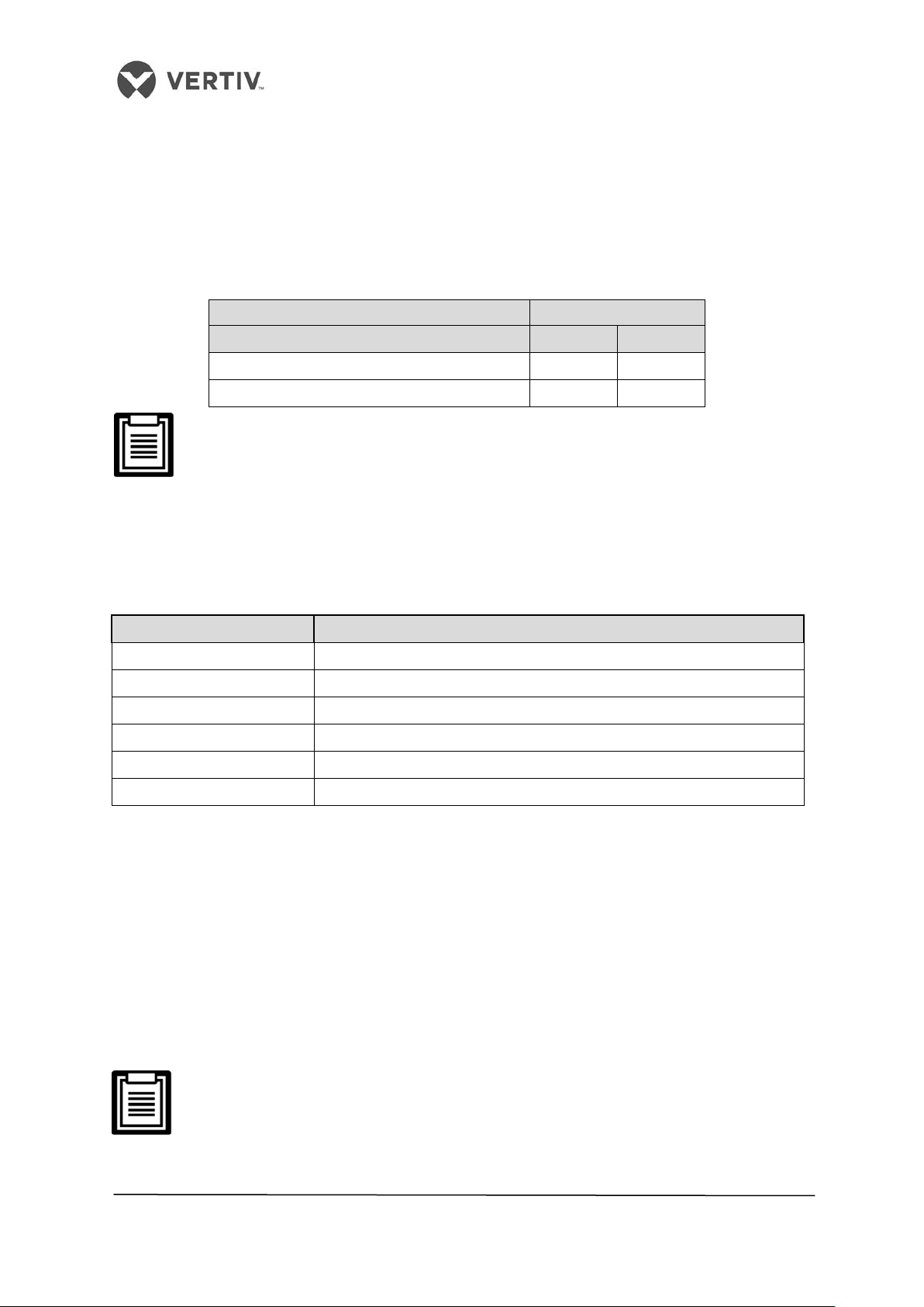
The Liebert LPC air conditioners come pre-charged in the factory with 2bar Nitrogen. The
table 2.9 indicates the standard charged amount. The users can determine the charging
amount of the refrigerant according to the system configuration and the length of the
connection pipes between the indoor and outdoor unit.
Table 2.9
Model of the Indoor Unit L1015
Model of the outdoor unit LSF24 LSF32
Outdoor Temperature
Standard charged amount (kg) 7.0 9.5
40 ° C 45 ° C
The standard charged amount refers to the sum of the charged amount for the
indoor unit, outdoor unit, and the 10m connection pipe.
There are scenarios where the connection pipe between the indoor unit and outdoor unit is
longer than 10m. In such cases, refill the refrigerant to the system as displayed in the table in
table 2.10 to ensure a smooth operational flow.
Table 2.10
Liquid Pipe (OD) Refrigerant refilling amount per meter of the Liquid pipe (kg/m)
12.7 0.107
16
0.174
19
0.245
22
0.321
25
0.431
28
NA
Refilling amount of the Refrigerant = Refilling amount of per unit length of the liquid pipe
(kg/m) * total length of the extended liquid pipe in meters.
On checking the table in Table 3.9, then the total length of the extended liquid pipe (in
meters) = Total length of the liquid pipe -10m
The refilled refrigerant will dilute the POE oil in the system and plays a major role in the
lubrication and cooling effects of the POE oil. Thus, it is for this purpose that the refrigerant
oil must be added. The added amount of POE oil of the Liebert LPC air conditioner is
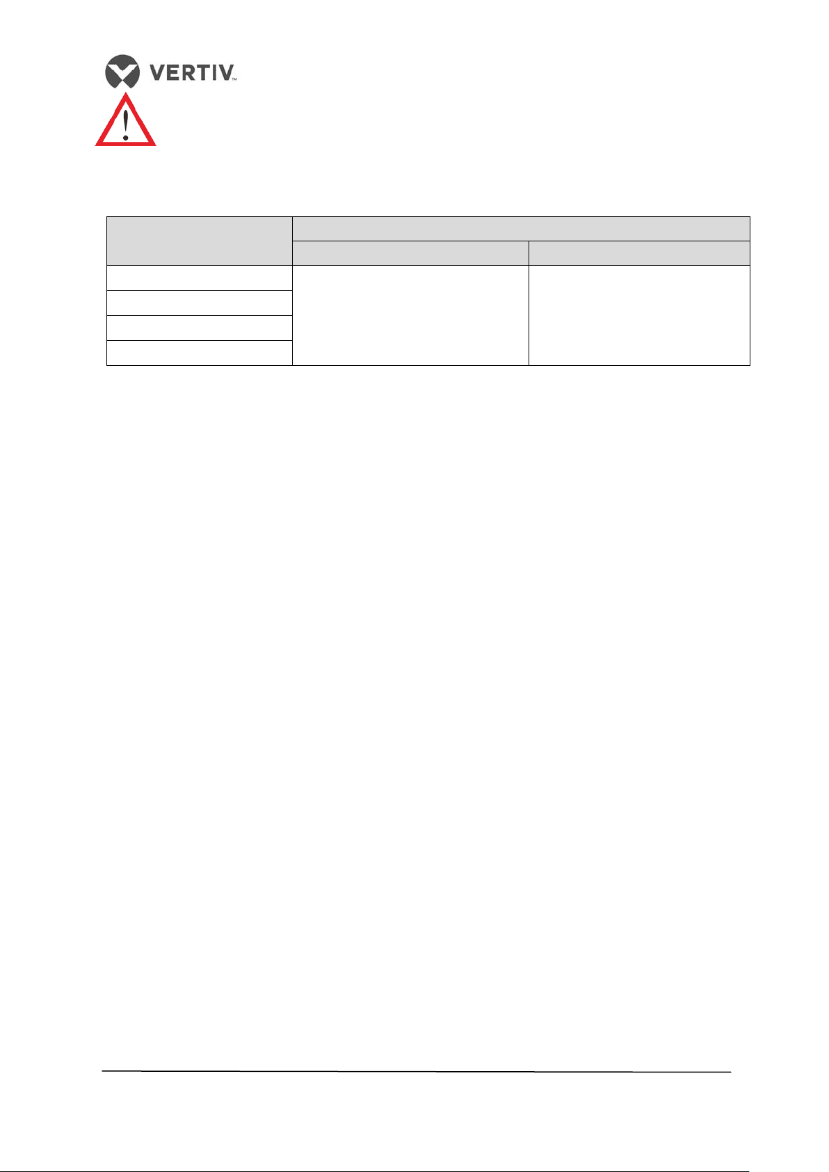
displayed in the table 2.11.
L1015 use the POE oil. Therefore, contact Vertiv Co. if there is a requirement
to add the refrigerant oil.
40
Page 41
Vertiv I Liebert LPC I User Manual
iameter of the liquid pipe in
Adding poor quality oil or oil for a different model will damage the system.
The quality issue due to the wrong refrigerant oil will result in the voiding of
the warranty.
Table 2.11
D
mm
Within 50m > 50m
L1015
12.7
16
19
22
Do not add refrigerant oil
Added Refrigerant Oil = (Added
amount of refrigerant for
length beyond 50m)
*
10%
2.9.6 Removing Fastener & Vibration Absorbers
Certain fasteners and vibration absorbers are mounted on the equipment to protect partial
components from getting damaged and distorted due to bumping, impact, and resonance.
Removal of these fasteners and absorbers is necessary before installation and
commissioning.
2.9.7 Removal of the transportation fixing plate from the compressor
Vibration absorbing cushions are added to the compressor base to reduce the vibration and
noise during the operation of the compressor. However, at times, such a technique cannot
control the vibration during transportation. This may result in loosened connection as well as
cause wear and tear of certain parts.
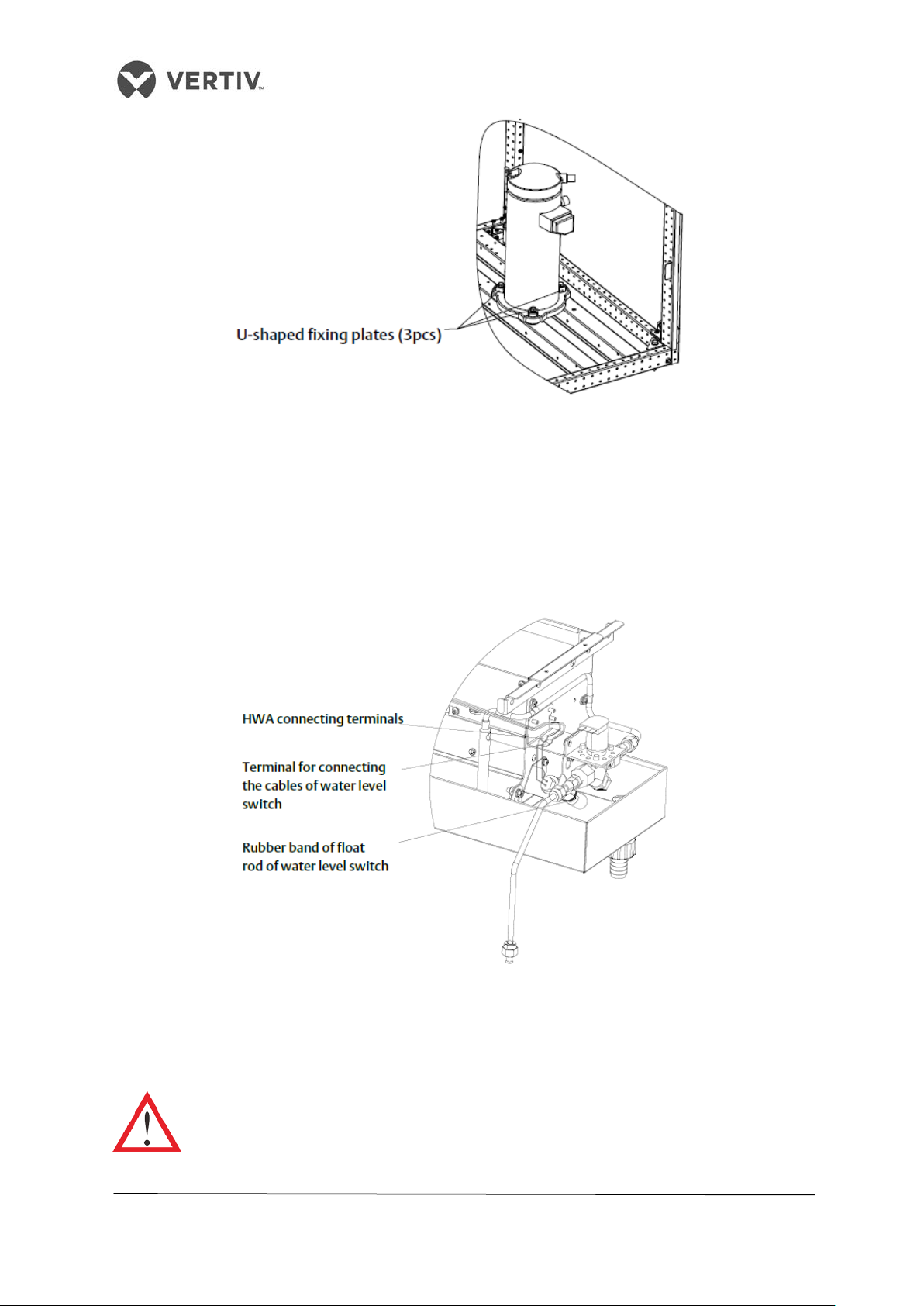
As a preventive measure, 3 U-shaped fixing plates are added to the 3 compressor bases
during transportation.
•
After the installation process and prior to the beginning of the Commissioning
process, remove the 3 U-shaped fixing plates.
•
Restore the bolts and washers in the reverse sequence of the disassembly process.
The fastening torque of the bolts is approximately (12 +/- 1) N-m.
Refer to the Figure 2-25 in order to view the position of the L-shaped fixing plate on being
fixed to the compressor base.
41
Page 42
Vertiv I Liebert LPC I User Manual
Figure 2-25 Fixed plates of the compressor
2.9.8 Removal of the fastener of infrared humidifier
The floating pole of the high-water level switch is tightly bound together with a rubber string
before delivery.
Figure 2-26 depicts the floating pole bound together with a rubber string:
Before operating as a unit, remove the rubber string failing which the unit cannot detect the
high water-level alarm.
Do not touch the lamps with bare fingers.
Figure 2-26 Removal of the Fastener of infrared humidifier
42
Page 43
Vertiv I Liebert LPC I User Manual
Sufficient space has been left around the unit for maintenance
fixed
The transportation fasteners have been removed
2.9.9 Removal of pipe fasteners
The pipes are either cushioned with foam or bound up before delivery. This is done to
prevent the long copper pipes from scratching the metal plate resulting in heavy damage.
These materials need to be removed before the start of commissioning.
2.10 Inspection of Mechanical Installation checklist
• Start the inspection and checks post the mechanical installation
• Pre-check and confirm that there are no discrepancies or faults
• Ensure that all the points in the sheet are ticked and are in compliance
Refer to the table 2.12 to view the Inspection sheet.
Table 2.12
Items Results
The equipment is installed vertically and the installation fasteners are
The charged 2 bar Nitrogen has been vacuumed
The pipes between the indoor unit and outdoor unit have been
connected and their respective ball valves have been opened
completely successfully
The Condensate pump has been installed (as per requirement)
The drain pipes have been connected
The water supply pipe for the infrared humidifier has been connected
All the pipe joints and hose connections have been fixed
Irrelevant stuff (such as transportation material, structure material,
debris, and
tools) have been cleared after installation of the equipment
The charged amount of refrigerants and lubricants has been roughly
calculated
The unit must have a plenum or air supply pipe connection;
Furthermore, the fan as well as the heater must not be accessible after
the installation
43
Page 44

Vertiv I Liebert LPC I User Manual
2.11 Electrical Installation
The electrical installation process includes the wiring of the indoor unit and condenser power
cables.
The following points discuss some aspects that are taken into consideration during the
electrical installation process:
• The connection of all the power cables, control cables, and ground cables should be as
per the local and national electrical regulations for that location.
• The electrical installation and maintenance must be performed by authorized
professional personnel.
• View the unit nameplate for the full load current. The cable sizes must be determined
based on the compliance with the local wiring protocols.
• Primary supply requirement: -380Vac (-10%`to +15%), 50 Hz, 3N.
• In case of damage to the soft power cable using a Y-connection, it must be replaced by
professional service experts.
• Prior to wiring, use a voltmeter to measure the power supply. While doing this, ensure
that the power supply has been switched off.
• TN and TT type star connections to the power distribution systems are used. If any
other type of connection is required, please call the support number for Vertiv Co.
• Use a breaking device in order to get disconnected from the power supply.
2.12 Wiring of the Indoor unit
The following section explains the procedure for the systematic wiring for the indoor unit:
2.12.1 Locating electrical ports of Indoor units
The location of the low voltage devices can be seen on opening the front door of the
electrical control box of the indoor unit. The distribution information of the low voltage
components is differentiated according to the labels on the cabinet.
44
Page 45
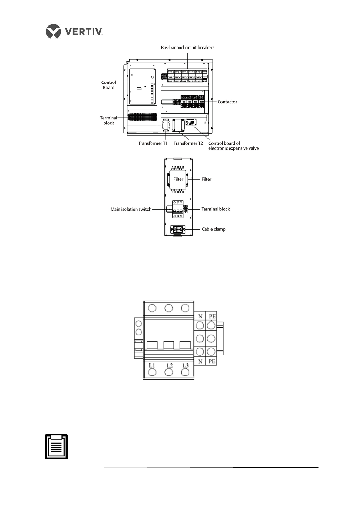
Vertiv I Liebert LPC I User Manual
Figure 2-27 Location of low voltage devices & electric control box
2.12.2 Connecting the power cable of the indoor unit
The power connectors are located as displayed in the preceding image (Refer Figure 2-27).
The enlarged view of the power connectors is shown in Figure 2-28.
Figure 2-28 Macroscopic view of the power connectors
Connect the terminals L1, L2, and L3, N, PE respectively to the corresponding counterparts of
the external power supply. Fix the cable to the cable clamp located at the inner side panel of
the unit.
The cable sizes should meet the local wiring regulations.
45
Page 46
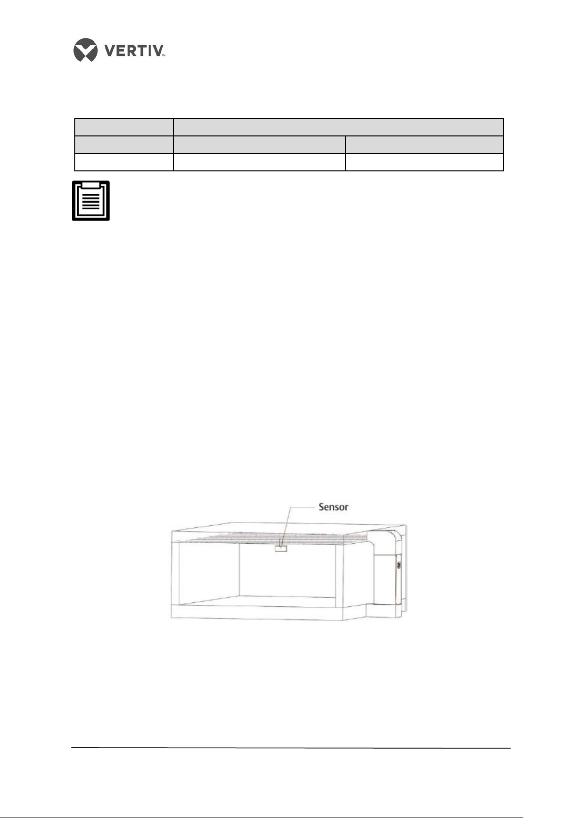
Vertiv I Liebert LPC I User Manual
L1015
25.8
35.1
Table 2.13 shows the cable specifications:
Table 2.13
Indoor unit (FLA - A)
Models With 1- stage electric heating With 2-stage Electric heating
The standard model is configured with a humidifier and 1-level electric heating.
This cooled unit excludes the condenser current.
2.12.3 Remote Temperature & Humidity Sensor placement
• When it comes to achieving high accuracy, the installation location of the remote
temperature and humidity sensors plays a crucial role. If the location is not selected
correctly, then the temperature and humidity control precision will not meet the
expected requirements. This can be quite critical, especially when there is a need for
ultimate temperature and humidity precision.
Moisture of the samples can adversely affect the sensors. Intense care must be taken while
installing the sensors.
• Vertiv recommends that the sensors be installed in the test area of the application
site. Ensure that the installation location is not affected by Heat dissipation.
• Another aspect is that the installation location must be as far as possible from the
staff area.
Single remote Temperature and Humidity sensor installation
Figure 2-29 displays the installation of a single remote temperature and humidity sensor:
Figure 2-29 Installation of a single remote temperature and humidity sensor
• If the Liebert LPC has one remote temperature and humidity sensor, a 20m sensor
cable will be configured by the factory.
• The remote temperature and humidity sensor must be installed 1.8m above the test
area floor so that the operator’s head on the site will not bump into the sensor. The
height should be kept adjustable.
46
Page 47
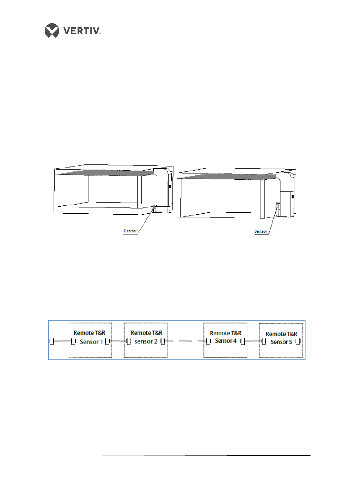
Vertiv I Liebert LPC I User Manual
• Another recommendation is that the sensor should be installed at the air return port
in the test area. This ensures that the installation location is not affected by fresh air,
irrespective of whether it is bottom air return or side air return.
Multiple remote temperature and Humidity sensors installation
Liebert LPC supports up to a maximum of 5 Temperature and Humidity sensors (inclusive of
the standard sensor, meaning 5-in-all).
• The controller can exercise control by selecting the max/min/average values of the
remote sensors.
Figure 2-30 shows the installation of 2 remote temperature and humidity sensors:
Figure 2-30 Location of 2 remote temperature and humidity sensors
• After the multiple sensors are connected in a series (Resembling a chain connection),
take the cable originating from the bottom of the unit.
• Connect the cable to the first sensor and then, from the first sensor to the second
sensor in a chain till all the sensors are connected to each other and the unit.
• Figure 2-31 shows multiple sensors connected in a series:
Figure 2-31 Chain connection of sensors in a series
47
Page 48

Vertiv I Liebert LPC I User Manual
2.12.4 Connecting the Control Cables
Figure 2-32 shows the amplified version of the field connection terminals.
Figure 2-32 Amplified version of Connection terminals
The upper part of the terminal block is connected to the unit whereas the lower part serves
as the user control signal interfaces.
The connection personnel must take anti-static measures before connecting the
control cables.
2.12.5 Connecting the water-under- floor sensor
• Each unit is equipped with an under-floor sensor. Connect one end of the sensor to
terminal 51# and the other end to the common terminal 24#.
• Though the number of sensors in parallel connection is not limited, each unit has only
one water-under-floor alarm.
2.12.6 Remote Shutdown
As shown in Figure 3-22, 37# and 38# can connect to a remote shutdown switch. These have
been shorted in the factory. The shorting cables must be removed if the terminals are
connected to the remote shutdown switch.
2.12.7 Customized Alarm terminals
• Terminals 50#, 51#, and 56# can be connected to 3 different kinds of sensors and
terminal 24# is their common terminal, defined for smoke and water-under-floor
sensors.
• After the customer terminals are connected with external alarm signals, set the
corresponding customized alarm using the controller.
When the contact is open, the external alarm doesn’t get generated. When the contact gets
closed, the external alarm is generated. In this case, the input state of the customer terminal
48
Page 49

Vertiv I Liebert LPC I User Manual
will be shorted. As a result, the air conditioner system will generate an audible alarm with the
PACC controller LCD displaying the alarm information.
• Terminals 50# and 24# are allocated for the smoke detector alarm switch.
• Terminals 37# and 38# are allocated for the remote alarm.
• Terminals 51# and 24# are allocated for the water- under-floor sensor as defined in
the factory settings.
2.12.8 External General Alarm
• Terminals 75# and 76# can be connected to the external general systems. They relay
output signals to the external alarm devices akin to an alarm indicator. When the
critical alarm occurs, the contact will get closed to trigger remote alarms and send
signals to the building management systems.
• Alternatively, it may dial the paging system automatically. The power supply of the
external alarm systems is prepared from the customer end (user-prepared).
2.12.9 SIC Card
Factory-installed
If the LPC unit is pre-installed with SIC card slot in the factory, the SIC card needs to be
checked for signal #A, #B. If the connection is directly taken from the control board as
depicted in figure 1-11, then, check the connections to the service tooling connection
terminals #77 and #78 of the control board.
Figure 2-33 SIC monitoring card factory installation wiring diagram
On-site installation
In the case of a SIC card, the customer needs to connect #A, #B, #GND and #12 on the SIC
card to #77, #78, #GND and #12V respectively on the terminal block.
49
Page 50

Vertiv I Liebert LPC I User Manual
Figure 2-34 On-site installation wiring diagram
2.12.10 Connecting the Solenoid valve of the Pipe Extension kit (Optional)
The Solenoid valve of the pipe extension kit has 2 control cables. These cables are used to
connect to the corresponding terminals of the control board. Refer to the Appendix for the
circuit diagram to understand it at a micro level.
2.12.11 Outdoor Wiring of the Condenser
This section explains the power supply wiring and connections of the control signal terminals
and control signal cables for the condenser:
External power supply wiring
The figure 2-35 depicts the external supply wiring of the condenser:
Figure 2-35 Condenser external power supply wiring
Connecting Condenser Control Signal Terminals
The control signal input terminals for the two circuits of the condenser are #70and #71. The
switching status is similar to that of the compressor.
Connecting Control Signal Cables
Open condenser electrical box sealing plate, showing the fan speed controller board. A
condenser connected to a control signal line wiring as follows:
A signal line required when the compressor enters the condenser through the external
electric power line box waterproof connector, the inner diameter of the joint is φ6mm.
50
Page 51
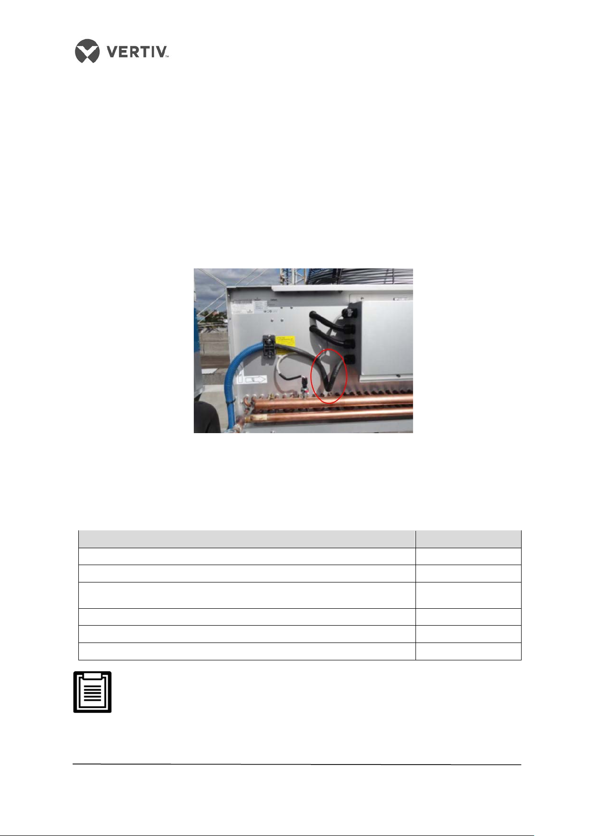
Vertiv I Liebert LPC I User Manual
Power cables and ground cables to the circuit breakers (MCBs), indoor unit,
J6 dry contact switch plate condenser speed control interface from the indoor unit #70 / #71
is introduced.
Power line connecting the condenser
Need to go through an external power line when the external power supply line waterproof
connector into the condenser electrical box, the inner diameter of the joint is dia.10mm.
To ensure high waterproof performance of the electrical box, if necessary, after the external
power source is connected. The waterproof connector is connected to the electrical box by a
glue application process. The external power cable from the source is required to be fixed to
the clip on the terminal, and the cable retaining clip holding the electrical box gland cable
between the U bend downward, as shown in following figure 2-36.
Figure 2-36 Condenser Wiring
2.12.12 Inspection of Electrical installation
Table 2.14 depicts the checklist for the Electrical Installation of the LPC model:
Table 2.14 Electrical Installation Inspection checklist
Items Results
The power supply voltage meets the rated voltage on the unit nameplate
The system electric loop has no open or short circuit
and condenser are well connected
The ratings of the circuit breakers (MCBs) and fuses are correct
The control cables are well connected
All the cables connections are fastened and screws fitted correctly
Do not switch the power on as Vertiv Co. authorized professional technicians
have to perform a check and confirm whether it is good to go. The commissioning
process will be performed by the Vertiv Co. subject matter experts and
technicians, therefore, do not power on the unit.
51
Page 52
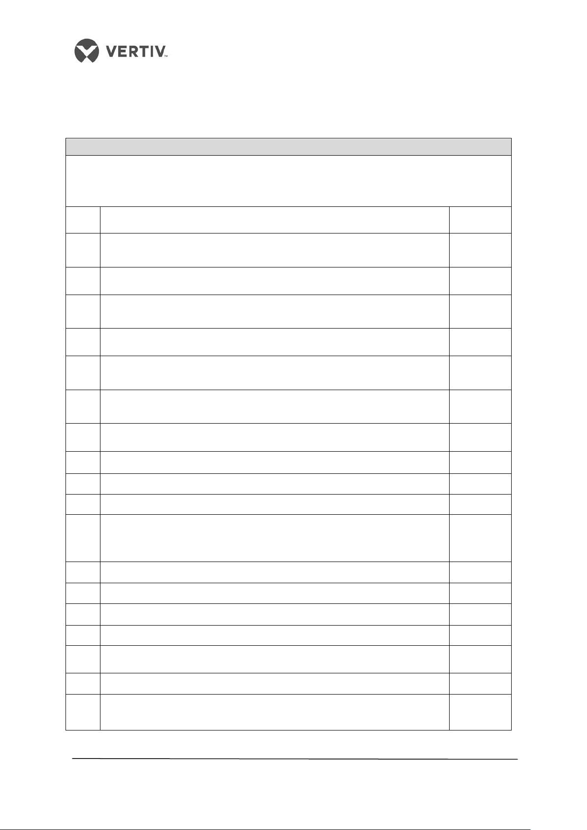
Vertiv I Liebert LPC I User Manual
brazing work
15
Copper pipe with insulation are tagged properly to indicate the brazing joints
2.12.13 Pre-Commissioning Checklist
Table 2.15 shows the Pre-Commissioning checklist for the Liebert LPC Model:
Table 2.15
Pre-Commissioning Checklist
Name of Customer:
Site Location:
Details:
S. NO Indoor Unit positioning & Power cabling, CU piping, GI piping Remarks
1 Indoor units are properly spaced from the maintenance point view, minimum
gap of 6" maintained on the back side & in between of the units
2 Proper levelling of Liebert LPC indoor stand with proper grounding
3 Drip tray installed properly with silicon sealant applied on the floor stand
corner
4 Units are installed properly with rubber pads in between the unit & the stand
5 Proper earthing is provided in the mains power supply as well as body earthing
for PAC unit
6 Power cable is provided with proper sizing of the cable to suit the full capacity
of CRAC unit
7 Power supply is connected to the mains switch with proper lugs & termination
8 Mains power cable is not routed with low voltage cables
9 Soap leak test on brazing joints & also in Cu piping
10 Pressure holding time
11 Quality of copper piping laying, equidistance in between two pipes; Quality of
copper piping laying, equidistance in between two pipes, Degree bends &
12 Initial U trap provided near the indoor unit
13 U traps provided after every 7 RMT in vertical length (based on the needs)
14 Inverted U trap provided near the outdoor unit
16 Proper support for refrigerant piping is configured
17 Copper pipes are painted with the proper color code
18 Additional piping kit installed in case of a vertical distance between indoor to
outdoor is more than 20RMT (or equivalent length exceed 30 Rmt)
52
Page 53

Vertiv I Liebert LPC I User Manual
one above the other
28
Condenser coils & Copper pipes U bends are painted with anticorrosive paint
19 Cable trays of proper gauges & quality are used. Ensure support is provided at
equal distance to avoid the sag on the cable tray
20 Dressing & proper routing condenser cable
21 Condenser cable & copper pipes are tagged with unit No & circuit no for easy
25 Proper supporting given for the condenser incase condensers are mounted
26 Concrete pedestal are provided for the condenser stand
32 Fresh water head pressure maintained of 21 - 100 PSI & with PPM level of 80 to
33 Ensure no leakage in the humidifier & drain piping before commissioning
53
Page 54
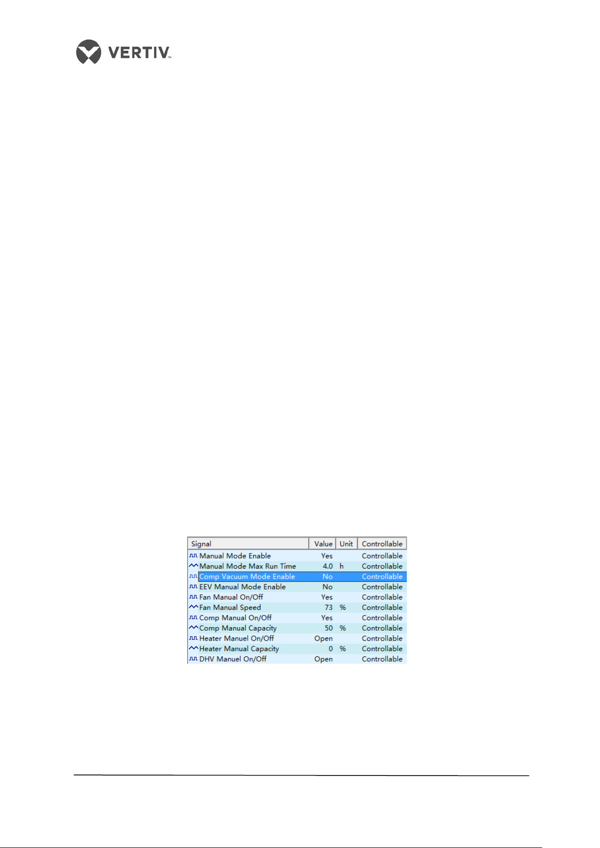
Vertiv I Liebert LPC I User Manual
3 Commissioning
3.1 Adding the Refrigerant
3.1.1 Packing
Before packing the unit, high pressure nitrogen gas is filled in the unit at a pressure of 25 bar.
With a dwell time of not less than 12 hours, the recorded holding pressure should be same
before and after this activity is completed.
3.1.2 Vacuuming the system
When the nitrogen gas is to be evacuated from the system, the ball valve from the indoor unit
should be opened simultaneously with the needle valve from the rear side of the electronic
expansion valve and the compressor discharge line respectively.
For longer refrigerant piping distances, a replacement operation is required, i.e. a pressure
lower than 20 Pa (absolute pressure) is to be maintained to add a small amount of refrigerant
charge into the system till the nitrogen evacuation process is complete. This may cause a
pressure below 20pa maintained for a considerable amount of time. Upon completion of the
evacuation process and charging the refrigerant to the desired pressure, the sight glass is
indicated green.
Engineering Standards propose an evacuation time of 4 hours. However, the same needs to
be adjusted according to the situation based on the refrigerant piping requirements at site.
3.1.3 Service tools operation on the controller
After completing the vacuuming process, the LPC background service tooling needs to be
accessed and in the manual control mode, the menu displays the system as evacuated, refer
figure 3-1. Manual mode enable is selected and Mode selection is controlled evacuation.
3.1.4 Manual operation for evacuation mode
If evacuation mode is not getting activated, the background service tooling menu needs to
be checked to ensure that the line solenoid valve and electronic expansion valve in an open
state along with high and low pressure setting of the needle deactivated simultaneously to
Figure 3-1
54
Page 55
Vertiv I Liebert LPC I User Manual
the tube portion 50m supplemental amount
perform the vacuuming operation. The flow of the refrigerant to LPC units is metered by a
solenoid valve equipped with a desiccant.
Ensure that the power to the unit is activated when the electronic expansion
valve is in an open position.
3.1.5 Adding refrigerant oil
LPC air conditioner uses R410A refrigerant, POE refrigeration oil. Adding refrigerant will
cause dilution of the system refrigerant oil and lubrication properties but the cooling
performance of depends on the quantity of refrigerant oil added to the system.
It is necessary to add lubrication oil to the system based on the details in the table 3.1 below:
Table 3.1
Liquid pipe diameter
(mm)
12.7
16
19
16
19
22
Within 50m > 50m
No supplemental
refrigeration oil
= The amount of additional refrigerant oil even
beyond
L1015
of refrigerant × 10%
3.1.6 The amount of refrigerant charge
LPS units are shipped from the factory with a pre-charged nitrogen gas at 2 bar pressure
before packaging. To calculate the amount of refrigerant gas required for LPC units refer
table 3.2. The system refrigerant charge depends on the configuration selected and the
length of the piping between the indoor and the outdoor units. If the piping length between
the indoor and outdoor unit exceed 10m refer table 3.3 for the quantity of additional
refrigerant to be charged in the system for proper functioning.
Table 3.2 Standard amount of refrigerant charge
Indoor Model L1015
Outdoor Model
Outdoor temperature
Standard filling amount (Unit: kg)
Note: The standard refers to an amount of charge indoor outdoor + charge amount to suit a piping
length upto 10m.
LSF24 LSF32
40 ℃ 45℃
6.4 9.5
55
Page 56
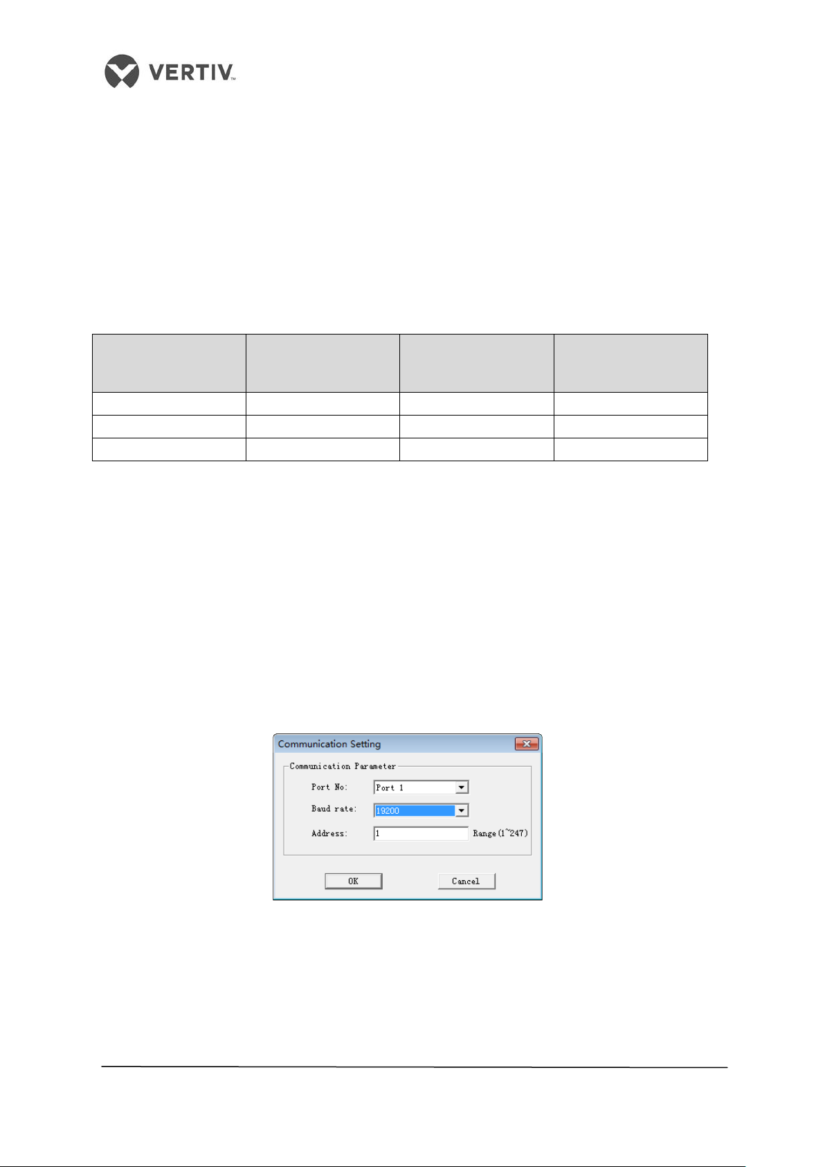
Vertiv I Liebert LPC I User Manual
The addition amount
The addition amount
16
0.174
25
0.431
An additional amount of refrigerant is calculated according to the formula:
The amount of additional cooling agent (kg) = liquid refrigerant amount added per unit
length (kg / m) × the total length of the liquid extension pipe (m).
The total length of extension piping for the liquid line (m) = Total length of the liquid pipe (m)
- 10m
Table 3.3 depicts the Different liquid line pipe diameters corresponding to the addition
amount of the liquid refrigerant per unit length of the tube outer diameter.
Table 3.3
Liquid pipe diameter
(mm)
12.7 0.107 22 0.321
19 0.245 28 /
of the refrigerant per
unit length (kg / m)
Liquid pipe diameter
(mm)
of the refrigerant per
unit length (kg / m)
3.2 Troubleshooting
LPC units operating on the new service operations model, utilizes a computer monitoring and
control feature to connect to the LPC units via the service tooling. Commissioning process
will monitor and output reports for service can be viewed via computer.
3.2.1 Tooling service connection
When service commissioning tooling terminal switch is connected to the terminal block # 77,
#78, open the software and select the corresponding communication parameters. Serial
number and computer equipment manager matches the COM port, baud rate consistent with
the device (device default 19200), as shown in Figure 3-2.
Figure 3-2 LPC services software communication parameters
56
Page 57

Vertiv I Liebert LPC I User Manual
Figure 3-3 Service software display interface
3.2.2 Start-Up Guide
On enabling a key service software debugging function, follow the prompts to step through
the various functions of the device detection and quantifying the refrigerant charge. Refer
figure 3-4 and figure 3-5
Debugging the functional devices according to step-wise function of detecting. LPC air
conditioning has a variety of operating modes. After setting the temperature and humidity of
the LPC units, if the output capacity of the compressor starts automatically varying with
changes in temperature and humidity, it is not a conducive condition for start-up.
Use a debug function key, the function to fix the output for easy debugging and testing.
Figure 3-4 Key service software debugging button
57
Page 58

Vertiv I Liebert LPC I User Manual
Figure 3-5 Key service software debugging interface
3.3 Commissioning steps
3.3.1 Terms
Exhaust superheat = exhaust gas temperature - the saturation temperature corresponding
to the exhaust gas pressure
Suction superheat = intake air temperature - the saturation temperature corresponding to
suction pressure (service software for display)
Oil sump temperature superheat = - saturation temperature corresponding to suction
pressure
= The degree of sub cooling condensate valve before the pressure corresponding to the
saturation temperature - temperature before the valve
3.3.2 Check the power supply
Each component corresponding to disconnect breaker, disconnector is closed and control
the total open space, to observe whether the "power alarm phase." If so, check the power
cable connection is valid.
3.3.3 Detecting the electrical heating element
On closing the electric heating breaker, change set-point temperature on the controller. This
will start the electric heater (or manual start) and then check each phase current to ensure
the electrical heating function is on.
58
Page 59

Vertiv I Liebert LPC I User Manual
3.3.4 Detecting the humidifier
On closing the humidifier breaker, change the set point of the humidity on the controller. This
will start the humidifier (or manual start) and then check each phase current to ensure the
humidifier function is on.
3.3.5 Condenser detection
Closing the condenser open space, the outdoor fan movable contact point, and to check
whether the normal running direction is detected by the input voltage.
3.3.6 Static charge
After the successful completion of vacuuming process, rapidly static charge the amount of
liquid refrigerant in the refrigeration system .
The high side and low side of the high and low pressure gauge are connected to the
composite needle and the electronic expansion valve needle ball valve at the mouthpiece
liquid respectively. The low-pressure valve is closed and the high-pressure valve is opened to
release most of the refrigerant charge to the condenser. If incase the condenser is unable to
accept the filling of refrigerant charge, the low-pressure valve is opened again, charging
refrigerant into the evaporator.
Static filling process to maintain the refrigerant container is placed upside down. Please keep
filling during warm-up state of the compressor.
3.3.7 Dynamic filling
If the compressor starting warm-up time is not enough, then one of the following methods
should be adopted to prevent compressor damage caused by flooding of the liquid
refrigerant:
Method 1: The open space open air conditioning compressor, and then adjust the set
temperature of the unit, the unit present cooling demand, the compressor contactor pull, and
then the compressor is turned off breaker is closed quickly after 1-2 seconds, wait five
minutes and then repeating the above steps (1-2 seconds to open the closed space, open
space disconnect, wait 5 minutes), repeated three times until the compressor and the liquid
is evaporated to form a film and can be started safely and operation of the compressor.
Method 2: Before starting the compressor housing lower portion with a blow dryer or other
heat source of about safety 30min, to vaporize any liquid refrigerant. By setting the
temperature / humidity, the unit has only cooling function activates the compressor (or
manual start) commissioned.
Compound pressure gauge valve fully closed, manually start the compressor operation
(output of the compressor 76%), when the system is operating normally, the low pressure
valve to maintain a small opening degree, reduce the risk of damage to the compressor.
59
Page 60

Vertiv I Liebert LPC I User Manual
Dynamic charging refrigerant gas (of R410A) until no bubbles within the liquid depending on
the mirror and the degree of subcooling condensate more than 5 ℃, suction superheat
degree of more than 14 ℃, oil superheat above 18 ℃. Real-time observation compressor
suction pipe, casing pipe and compressor to ensure no condensation phenomenon to rule
out the potential danger of liquid slugging. Units exhaust superheat is in the range of 25 ℃ ~
40 ℃.
3.3.8 Inspection after completion
1. After commissioning, the unit should focus on checking whether the parameters
revert to the default or initial value.
2. If a debugger is used when a manual mode for functional testing, commissioning
and after the manual mode should be changed back to automatic mode.
3. Check whether the water supply unit connected to a leak, the fixed line is normal.
4. Check the drainage unit is smooth, condensate drain connections for leaks.
5. Check the compressor intake and exhaust port is loose, whether there is oil leakage.
6. Recording parameters fill in commissioning report and submit it to the customer.
60
Page 61

Vertiv I Liebert LPC I User Manual
SYSTEM OPERATION &
GENERAL MAINTENANCE
PART III
61
Page 62
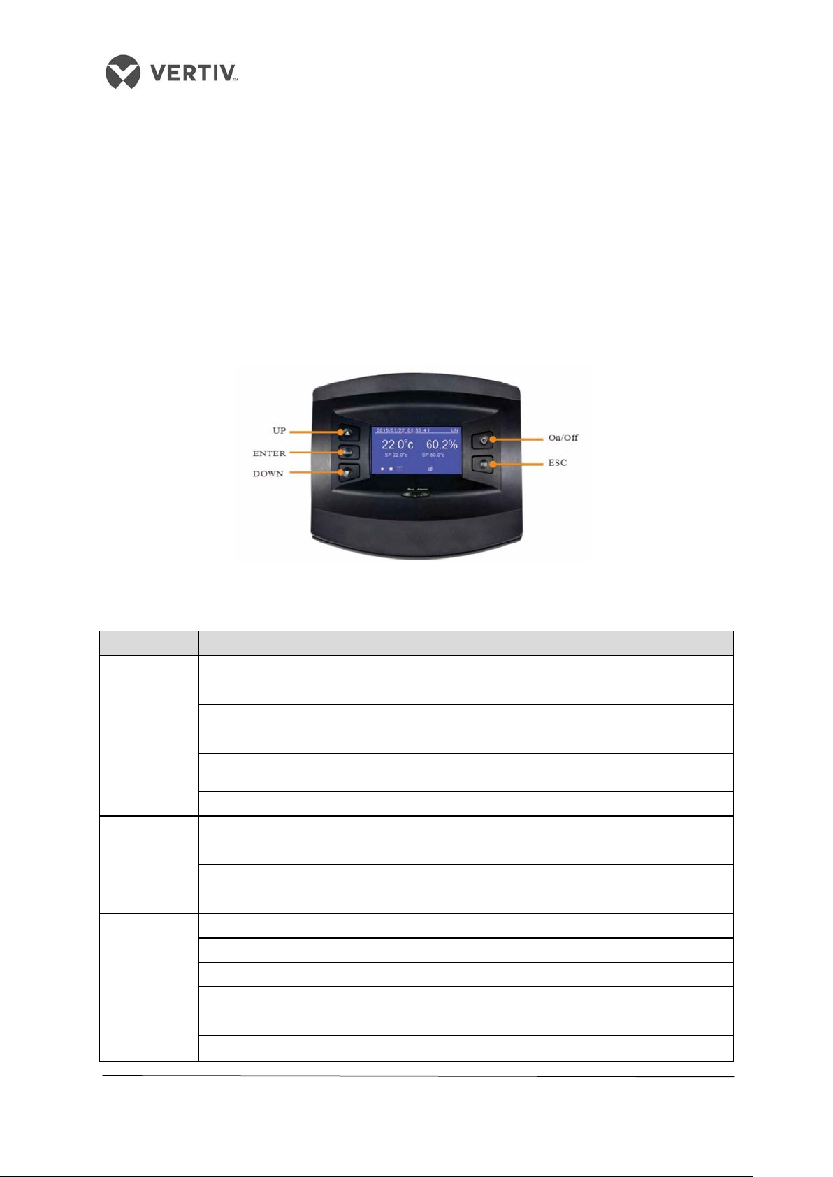
Vertiv I Liebert LPC I User Manual
•
Press this key to discard changes
•
•
•
•
•
Press this key to decrease the value of the displayed parameter
•
Press this key to move to the next menu
4 Controller
The Liebert LPC models uses a PACC controller which has a simple user interface. It has an
easy-to-operate menu structure.
4.1 Display
The display board uses a 240x128 dot-matrix backlight LCD which has a blue-colored
interface, which displays clear texts and graphics on the panel. A color display option is too
available as an enhanced feature.
4.2 Control Keys
Figure 4-1 Controller
Table 4.1
Key Function Description
On/Off Press this key to Switch on or Switch off the controller
This key has several functions, namely –
•
Press this key to quit the current menu and hop to the previous menu
ESC
Up
Down
•
Holding this key will display the help menu along with info such as the maximum,
Press this key to mute the audio alarm
This key has several functions, namely -
Press this key to move the cursor upwards
•
Press this key to increase the value of the displayed parameter
Press this key to move up on multi-screen displays
This key has several functions, namely –
Press this key to move the cursor downwards
•
Press this key to scroll downwards on multi-screen displays
Enter
•
Press this key to save the settings after change in the parameters or values
62
Page 63

Vertiv I Liebert LPC I User Manual
Operation Indicator
Green
Solid
The controller is working properly
Flashing
An alarm alert occurs
4.3 Indicators
The controller has built-in indicators, namely- Operation indicator and Alarm Indicator. The
indicators along with their functionalities are defined in the table 4.2.
Table 4.2
Indicator Color Status Function Description
Alarm Indicator Red Off No alarm alert
4.4 Control Interface
Once the power is turned on, the LCD screen displays the communication state. If there is no
communication between the controller and target interface board, the LCD will display the
“Communication Failure” notification. However, if the communication is successful, the
screen displays the shutdown or main interface based on the On or Off state of the air
conditioner. The control interface mainly displays the main interface, shutdown interface, and
password.
4.4.1 Main interface
Once the air conditioner is powered on wait for the successful communication following
which the main interface will be displayed as depicted in Figure 4-2.
Figure 4-2 Main interface
The Display will be in screen-saver mode in case of no action or if no key is pressed within
the initial 10 minutes. The Blue background display eventually turns off. To work with the
controller, press Enter to view the main menu. On clicking, the main interface displays the
date, time, day of the week, display board address, actual temperature and humidity, humidity
set point, and unit work icons (such as fan, cooling, and on/off standby mode).
The main interface consists of three modes related to the operation of the unit, namely-
• Dynamic Running state icons
• Locking state icons
• On/Off/Standby state icons
63
Page 64
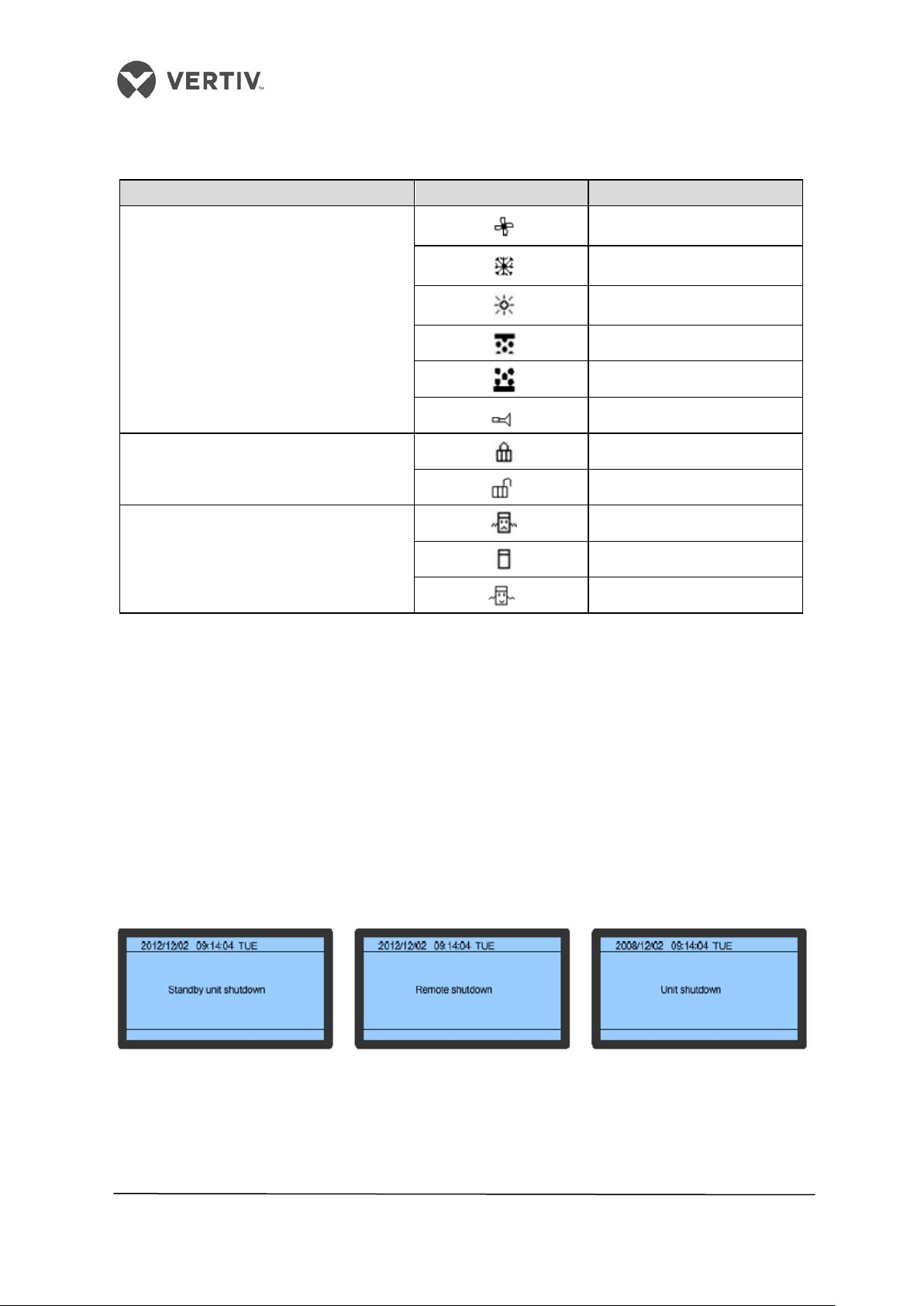
Vertiv I Liebert LPC I User Manual
Fan Running
Cooling
Heating Status
The following table 4.3 shows the functions and their descriptions for the icons:
Table 4.3
Mode Icon Definition
Dynamic Running State
Locking Stat
On/Off/Standby State
Humidifying
Dehumidifying
General Alarm
Locked
Unlocked
Standby
Shutdown
Running
4.4.2 Shutdown Interface
If the air conditioner is in the Shutdown status, on successful communication, the controller
will display the shutdown interface. The Display’s Shutdown interface depends on the
shutdown mode of the unit, namely –
• Standby Unit Shutdown
• Remote Shutdown
• Unit Shutdown
Figure 4-3 shows the 3 shutdown controller modes based on the shutdown state of the air
conditioner:
Figure 4-3 Shutdown interface
64
Page 65
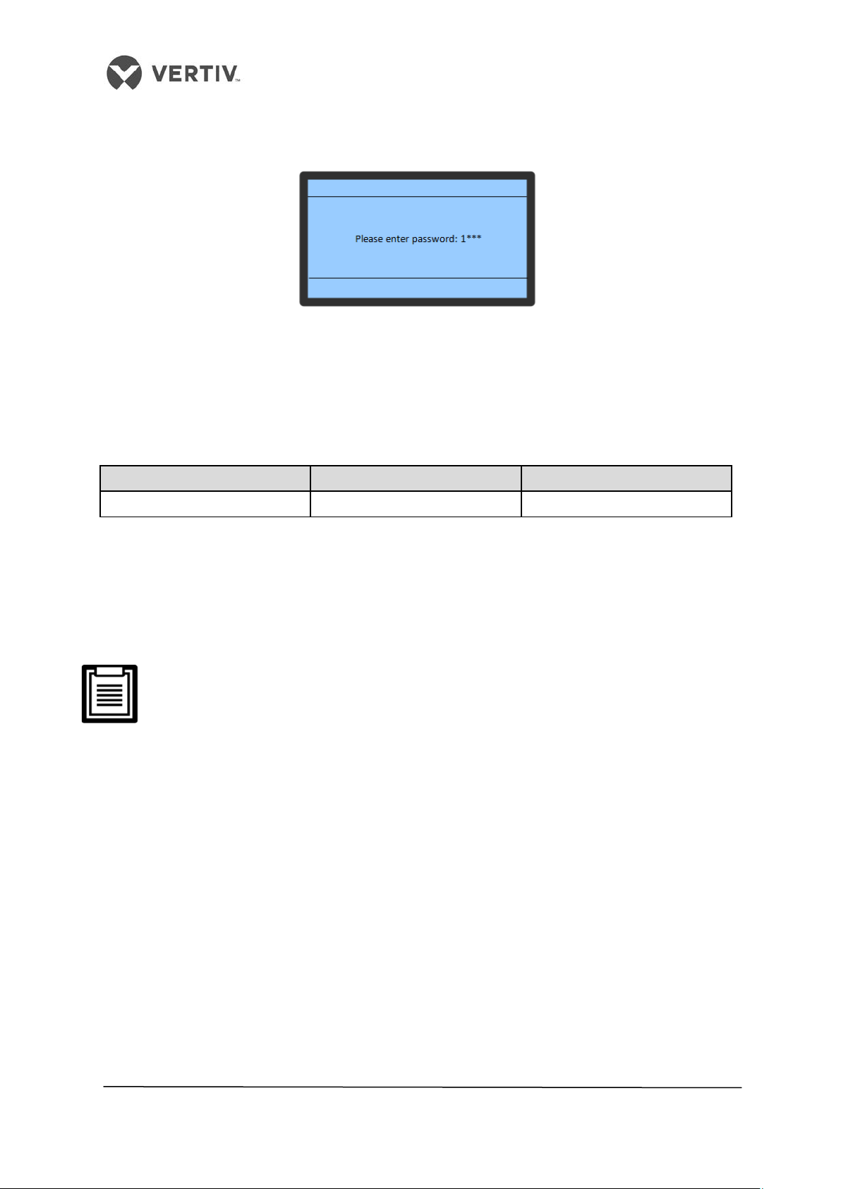
Vertiv I Liebert LPC I User Manual
4.4.3 Password Interface
Password Level
User
Initial Password
Figure 4-4 shows the password interface:
Figure 4-4 Password Interface
Press the Enter key on the controller to start working with the main or shutdown interface.
Enter the password to start working with the main or shutdown interface. Table 4.4 shows
the password level, user type, and initial password for the Liebert LPC model:
Table 4.4
Level 1 General Operator 0001
Step-by-Step instructions on the password interface are stated below:
• Press the Enter key in the mai
• Press the Enter key to highlight the input data field in the password
interface
• Press the Up or Down keys to change the current number
• Press the Enter key again to confirm the password and enter the Main menu
• If the p
password screen.
• If on pressing the Enter key, no password is entered on the
password screen, the setting values can be checked but cannot be
change
• LP
setting advanced password for maintenance.
assword entered is incorrect, press the ESC key to return to the
d.
C air conditioners uses background service software control, without
n interface to view the password interface
4.4.4 Menu Structure
The Controller menu has a step by step structure. After the main interface, press the Enter
key to enter the password screen. Type the password and access the main menu and
submenus parameter query.
4.5 Main Menu
• On entering the password, the Main menu can be viewed. In the Main Menu Press the
Up/Down key to scroll the cursor. Select the required sub-menu.
• Press Enter to gain access to the second level sub-menu.
The Main Menu contains 7 sub-menus, divided into 2 displays as depicted in Figure 4-5.
65
Page 66
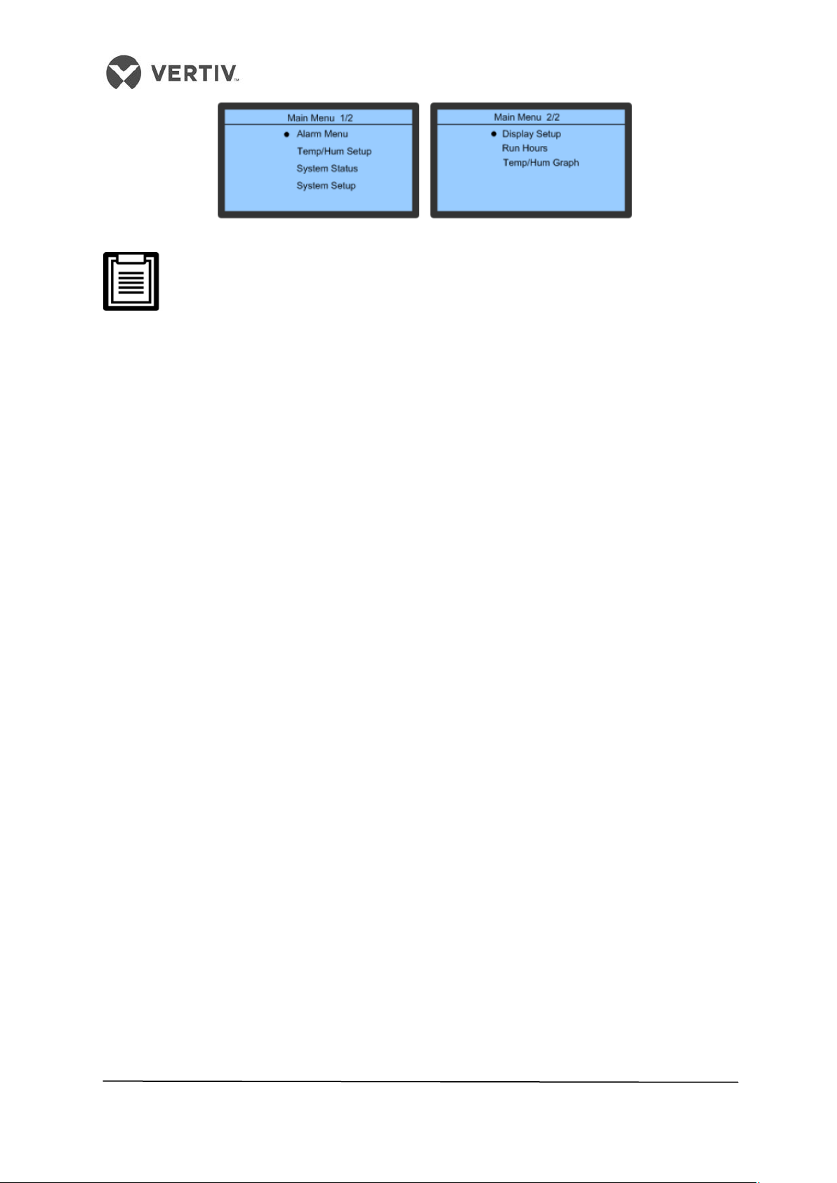
Vertiv I Liebert LPC I User Manual
Figure 4-5 Main Menu
• A black dot is displayed to the left of a menu-item in the preceding Figure 4-5.
The black dot indicates that the menu has a sub-menu or settings for the
parameters of that menu can be configured/modified/altered.
• After changing the parameters, if Enter is not pressed, remote alarm
temperature maintains the previous set parameters.
4.5.1 Setting parameters for the sub-menu
Following is the procedure for setting parameters for a menu item:
• For any menu-item, use the Up/Down key to move to the sub-menu, which needs to
be worked upon.
• When the cursor is on the selected menu, a black dot appears on the left-hand side of
the sub-menu.
• Next, press the Enter key to further explore the sub-menu or set parameters for that
menu.
Consider an example that illustrates the procedure for such a menu:
• Press the Up or Down key in the Main interface to move the cursor to the Alarm
menu. Once the cursor moves to that sub-menu, the black dot is displayed to the left
of that menu.
• Press the Enter key to explore the Alarm menu interface.
• Press the Up or Down key in the Alarm menu to move the cursor to the Alarm Setup
sub-menu.
• Press the Enter key to explore the Alarm Settings sub-menu
• Press the Up or Down key in the Alarm Settings menu to move the cursor to the High
Temp Alarm.
• Press the Enter key to highlight the parameter for the High Temp Alarm option.
• Press the Up or Down key to select the required parameter.
• On selecting the parameter, Press the Enter key to confirm and validate the
parameter.
• Press the ESC key to move back to the higher-level menu.
66
Page 67

Vertiv I Liebert LPC I User Manual
Path
User sub-menu function
User submenu function
Alarm History
Query the history of the alarm records
Alarm Settings
Set the Alarm values
Temperature & Humidity
Query and set the Temperature or
Sensor Status
Calibrate the remote temperature and
Power Supply status
Query the input power and frequency
Communication settings
Set the communication, address and
Time settings
Set the time
4.6 User menu
User menu helps to set the parameters. The various user functions are described in the
Table 6.5.
Table 6.5
Main Menu --> Alarm
Menu
Main Menu
Main Menu --> System
status
Alarm Status Query the current Alarm status
Alarm Process Clear the Run time of the filter after
the maintenance screen
Settings
Display Settings Setting the address of the monitor, the
Operation Hours Detect the operational time for the
Temperature & Humidity curve Query the Temperature/Humidity
Humidity parameters
contrast in the display, and reminder service
hotline
main components in the unit
change trend within a range of 6-48 hours
humidity sensors and the return air
temperature humidity sensors.
of the power
Main Menu --> System
Settings
Password settings Setting a password
baud rate
67
Page 68

Vertiv I Liebert LPC I User Manual
4.6.1 Alarm Menu
In this section, the Alarm menu and its corresponding functionalities, which are an integral
part of the controller ecosystem, will be discussed to help understand how it works.
• Press Up or Down in the Main Menu (1/2) to move the cursor to the Alarm menu.
• Press the Enter key to explore the Alarm menu.
Figure 4-6 shows the 4 sub-menus within the Alarm Menu:
Figure 4-6 Alarm Menu
4.6.2 Alarm Status
The Alarm Status is used to record all the active alarm statuses.
Figure 4-7 shows a sample of the Alarm Status function:
Figure 4-7 Alarm Status
Following are the status types included under this function:
• Active Alarms (Total alarm number)
• ALM (Alarm Serial Number and Type)
• Time (Alarm Start and End Time)
The controller can store up to 100 Alarm Status records at a given point of time.
Alarm statuses will be automatically cleared in case of a power failure.
68
Page 69
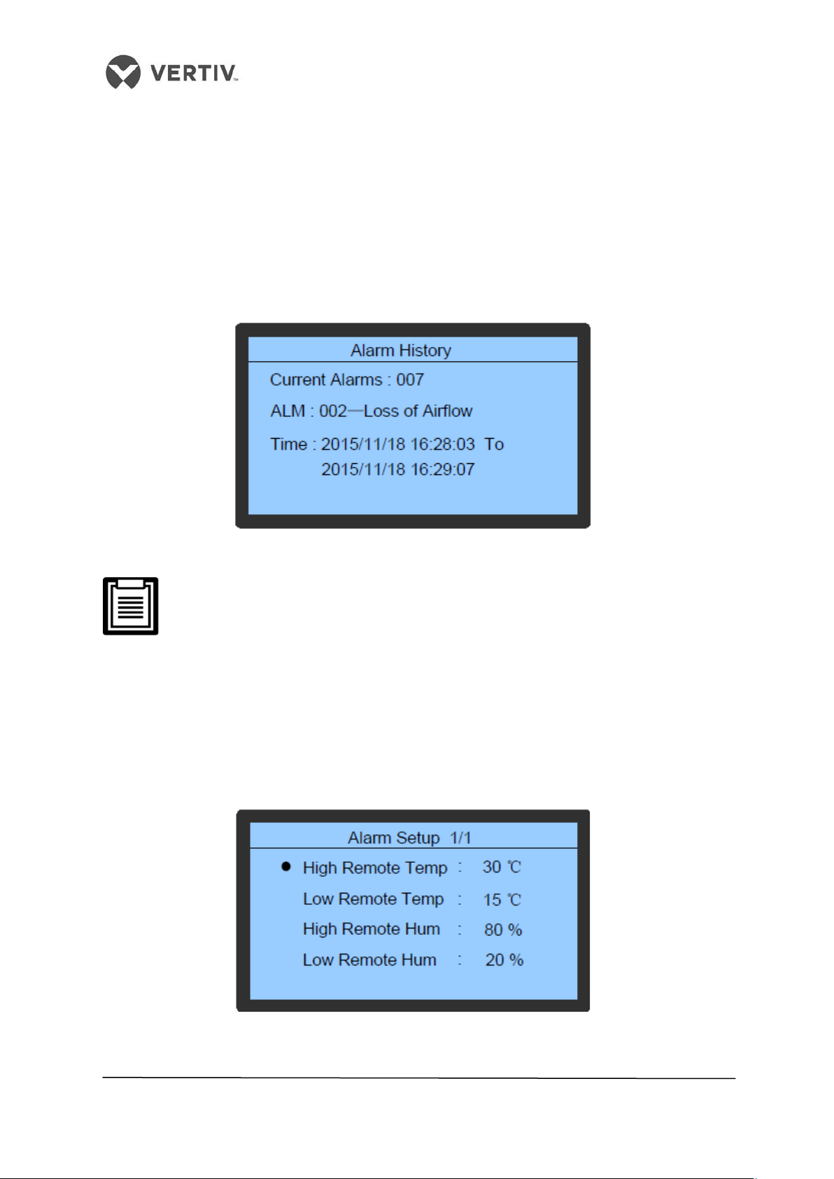
Vertiv I Liebert LPC I User Manual
4.6.3 Alarm History
The Alarm History is used to query the history of the alarm records.
Following is the information included in the Alarm History function:
• Active Alarms (Total number of Alarms)
• ALM
• Alarm Time
Figure 4-8 depicts the Alarm History on the LCD screen of the controller interface:
Figure 4-8 Alarm History
At times, several alarms are generated at a given point of time. In such scenarios,
the alarm with the biggest alarm SN (read Serial Number) is the latest alarm.
Press the Up or Down key to scroll through the alarms. The controller can store
up to 500 history alarms and these records will remain intact even in the case of a
power failure.
4.6.4 Alarm Setup
The Alarm Setup function contains set points that define the configuration of the system.
Figure 4-9 shows the Alarm Settings interface:
Figure 4-9 Alarm Setup
69
Page 70

Vertiv I Liebert LPC I User Manual
Do not change the default configurations of the alarm set points. However, if
modifying or changing the set points is a requirement, then ensure that the set
points are changed under the guidance of trained professionals.
4.6.5 Alarm Process
The Alarm Process function deals with the settings related to the maintenance and
replacement of the filter. It can be configured so that an alarm alert will be generated once
the due date arrives.
This facilitates the periodic checking and upkeep of the filter. If the Filter Maintenance is set
to Yes, clear the filter running time to zero.
Figure 4-10 Alarm Process
4.6.6 Temperature & Humidity Setup
This function is used to set the temperature and humidity settings.
• In the Main Menu (1/2), move the cursor to the Set Point control by using the Up and
Down keys.
• Press the Enter key to explore the sub-menu of the Set Point Control Interface.
The options in the sub-menu are used to set the temperature, humidity, and altitude of the
operational unit.
Figure 4-11 shows the interface of the Temperature and Humidity settings menu:
70
Page 71
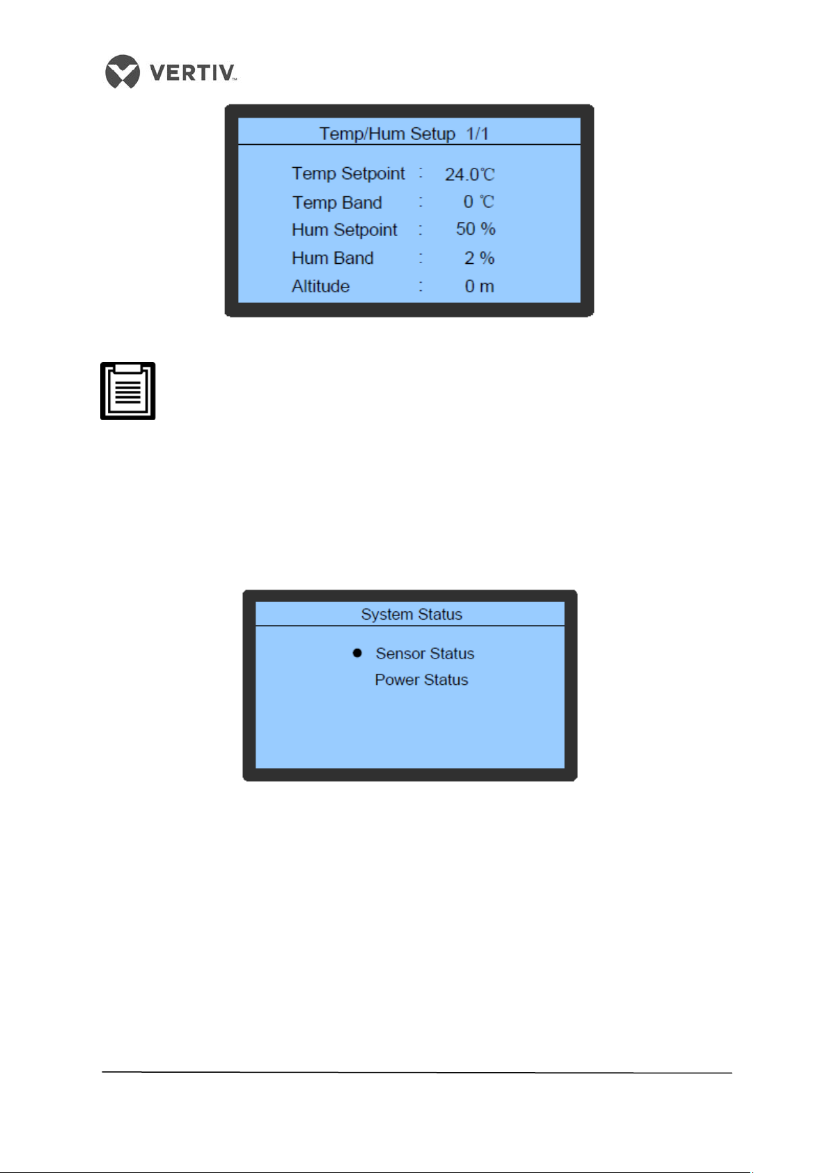
Vertiv I Liebert LPC I User Manual
igure 4-11 Temperature and Humidity Setup
F
Depending on the requirement, the temperature and humidity must be set
appropriately. Do not set the precision temperature or humidity too high as it will
result in high energy consumption. Do not set it too low either as the environment
cannot be simulated as per the requirement. Altitude must be set based on the
local unit of the actual application settings. Set the Altitude value correctly lest it
affects the precision required for accurate results.
4.6.7 System Status
The System Status can be viewed in the Main Menu (1/2) screen.
Press the Enter key, following which the unit temperature and humidity sensors can be
calibrated. Even the power status parameters can be queried.
Figure 4-12 System Status
71
Page 72
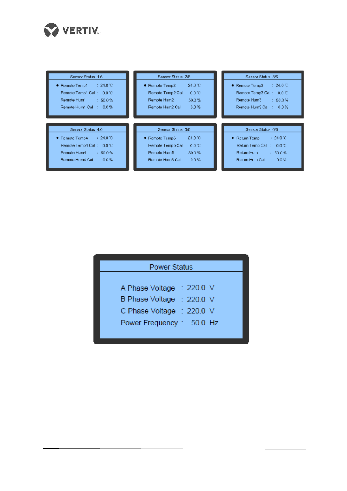
Vertiv I Liebert LPC I User Manual
4.6.8 Sensor Status
Figure 4-13 shows the Sensor Status.
Figure 4-13 Sensor Status
In Figure 4-13, the Sensor Status from 1/6 to 5/6 screens show the detected values of
temperature and humidity of remote and calibrated values. The Sensor Status 6/6 screen
shows the detected values of the return air and its calibrated values.
4.6.9 Power Status
Figure 4-14 displays the Power Status menu:
Figure 4-14 Power Status
The Power Status menu is used to browse and view the input power status of the air
conditioner such as the A-Phase voltage, B-Phase voltage, C-Phase Voltage, and Power
Frequency.
72
Page 73

Vertiv I Liebert LPC I User Manual
4.6.10 System Setup
Figure 4-15 shows the different options or menu-items of the System Setup screen:
Figure 4-15 System Setup
• Move the cursor to the System Setup menu.
• Press Enter to view the sub-menu of the System Settings menu item.
It contains 3 settings, namely –
• Monitor Setup
• Time/Date Setup
• Password Setup
4.6.11 Monitoring Setup
Figure 4-16 shows the Monitoring Setup menu:
Figure 4-16 Monitoring Setup menu
73
Page 74
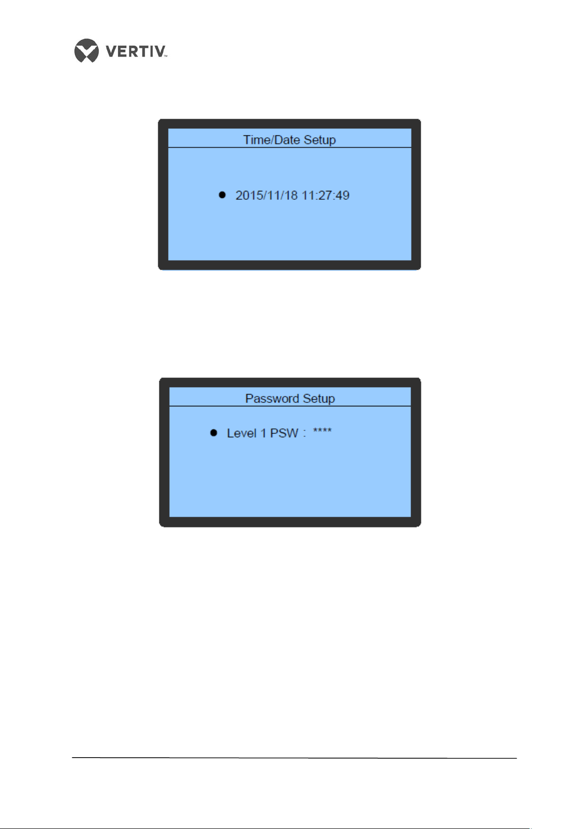
Vertiv I Liebert LPC I User Manual
4.6.12 Time/Date Setup
Figure 4-17 shows the Time/Date settings screen:
Figure 4-17 Time/Date setup
Set the time and date using these specific settings.
4.6.13 Password Setup
Figure 4-18 shows the Password settings screen:
Figure 4-18 Password Setup
Passwords can be setup and modified using this function.
74
Page 75

Vertiv I Liebert LPC I User Manual
4.7 Display Setup
• Press the Up or Down key on the interface of the Main Menu (2/2) to move the cursor
to the Display Setup
• Press Enter to enter the sub-menu of the Display Setup function
Figure 4-19 shows the sub-menu of the Display Setup function:
Figure 4-19 Display Setup
The Display Setup function helps in the process of defining the CAN Communication
address of the display board and display contrast.
4.8 Run Hours
• Press the Up or Down key to move the cursor to the Main Menu (2/2) and move to the
Run Hours option
• Press Enter and on accessing the Run Hours screen, the total run hours of a fan,
compressor, heater, humidifier, and the Cumulative run time can be browsed.
Figure 4-20 shows the Run Hours sub-menu:
Figure 4-20 Run Hours
75
Page 76
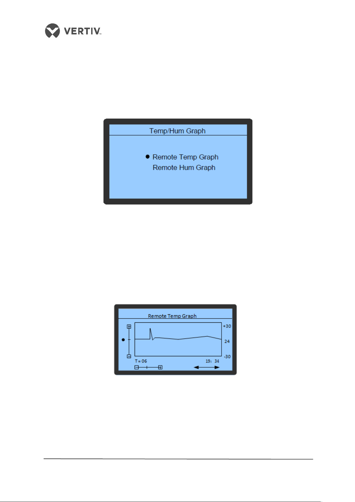
Vertiv I Liebert LPC I User Manual
4.9 Temperature and Humidity graph
On the main interface (2/2), move the cursor using the Up or Down key to the Temperature
and Humidity Graph menu. Through the menu, browse and view the temperature as well as
the Humidity graphs. These graphs reflect the change in temperature and humidity over an
earlier time period.
Figure 4-21 shows the Temperature/Humidity Graph menu:
Figure 4-21 Temperature and Humidity Graph menu
In the first option, click on the Remote Temp Graph options to access the Temperature sub-
menu as depicted in Figure 4-22. In the graph, the current temperature is the origin, time is
the horizontal axis, and temperature is the vertical axis. The graph displays the temperature
changes from 6h to 48h through the zooming operation and controlling cursor movement.
Press the Up and Down key to move the cursor to the required zoom-control bar. Press the
Enter key to enter the editing mode and zoom in or zoom out the graph using the Up and
Down key.
Back to the Temperature and Humidity Graph menu interface, choose the Hum Graph menu.
Figure 4-22 Temperature Graph
76
Page 77

Vertiv I Liebert LPC I User Manual
Figure 4-23 Humidity Graph
In the graph, the current humidity is the origin, time is the horizontal axis, and humidity is the
vertical axis. The graph displays the humidity changes from 6h to 48h through the zooming
operation and controlling cursor movement. Press the Up or Down key to move the cursor to
the required zoom-control bar. Press the Enter key to enter the editing mode and zoom in or
zoom out the graph using the Up and Down key.
The following is a brief overview of the Remote Monitoring Mode:
The Liebert LPC humidity air conditioners support the multiple monitoring modes:
• Connecting the RDU and SiteWeb - A monitoring system developed by Vertiv Co.
Alternatively, A third-party monitoring system can be used in compliance with the
standard protocol of the Ministry of Industry and Information technology.
• Connecting RDU and SiteWeb- a monitoring system developed by Vertiv Co. or any
third-party application via the Modbus- RTU protocol.
• Connecting the network management software using the SIC card and the SNMP
protocol
The communication cables of the remote monitoring system are connected to the #77 and
#78 terminals in the electric control box. Refer to the Appendix section for the Circuit
Diagram to understand it better.
77
Page 78

Vertiv I Liebert LPC I User Manual
5 General Maintenance
The operation and maintenance of the Liebert LPC models will be explained in the chapter.
It includes the routine maintenance and inspection items, checks related to electric
connections and wiring, visual inspection (related to the appearance), and drainage
maintenance among other checks, that helps the customer gain sight in to the general
maintenance of the LPC series of air conditioners.
Prior to operation and maintenance, lethal voltage may be present in the
equipment which can be fatal. All notes, warnings, and cautionary warnings
marked on the equipment as well as the ones mentioned in the manual must
be considered, otherwise, it may lead to injury and fatality.
Qualified and Professional Maintenance personnel are the ones supposed to
operate and handle the equipment. Careful and cautionary measures are
conveyed to the professional personnel and therefore, only these personnel
may perform maintenance on these machines.
78
Page 79
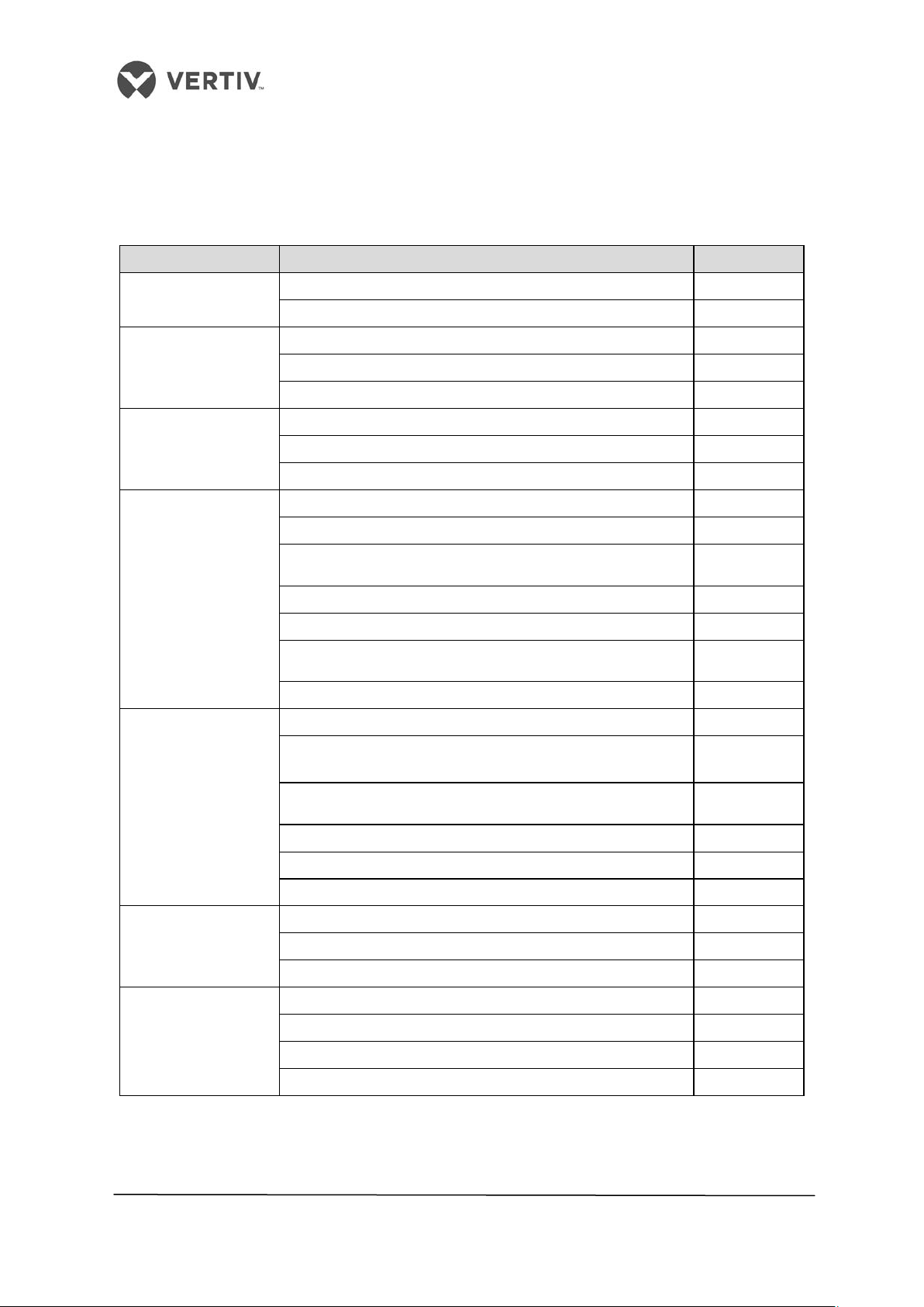
Vertiv I Liebert LPC I User Manual
Check and fix connectors
Check and fix connectors
Check the vibration absorbing cushion for ageing and
damage
Check SPD board once a week during
thunderstorms and similar situations
Check refrigerant pipes
pressure
Check moisture conditions in the system using the
C heck eroding of components
Check the functioning of electrical heating
Check the Humidifier Lamp
Check the water pan for mineral deposits
5.1 Routine Monthly Inspection
The table 5.1 displays the system components that need to be checked monthly for
symptoms of wear and tear and whether the components function correctly.
Table 5.1
Components Inspection Notes
Filter
Fan
Compressor
Air-cooled
condenser
Check the filter for clogging and damage
Clean the filter
Check if the fan blades are distorted
Check bearings for wear and tear
Check for Leakage
Check for noise and vibration
Cleaning the Condenser fins
Fan Base is rigid
Check if the SPD board is working correctly
Adjust the controller speed
Check if refrigerant pipes have suitable support
Check if the suction is too hot and check for suction
Cooling system
liquid
Check the discharge pressure
Check the electronic expansion Valve
Check for Exhaust Air pressure
Heating system
Check and fix connectors
Check water pan drainage for clogging
Infrared Humidifier
Check and fix connectors
79
Page 80
Vertiv I Liebert LPC I User Manual
Components
Inspection
Notes
Regulate function of the speed regulator
Check if refrigerant pipes have suitable support
Check if the suction is too hot and check for suction pressure
Check the functioning of reheat system components
Check water pan drainage for clogging and the water pan for
Check and fix connectors
Check the closing condition of the contactor
5.2 Routine Bi-annual Inspection
The table 5.2 displays the system components that need to be checked twice a year for
symptoms of wear and tear and whether the components function correctly.
Table 5.2
Filter
Fan
Compressor
Air-cooled condenser
Check the filter for clogging and damage
Clean the filter
Check if the fan blades are distorted
Check bearings for wear and tear
Check and fix connectors
Check for Leakage
Check and fix connectors
Check for noise and vibration
Cleaning the Condenser fins
Fan Base is rigid
Check the vibration absorbing cushion for ageing and
damage
Check if the SPD board is working correctly
Check SPD board once a week during thunderstorms and
similar situations
Check and Fix connectors
Check refrigerant pipes
Check moisture conditions in the system using the liquid
indicator
Cooling system
Heating system
Infrared Humidifier
Infrared Humidifier
Electric Control
section
Check the discharge pressure and condensing sub cooling
degree
Check the electronic expansion Valve
Check if the refrigerants needs to be added to the system
using the liquid indicator or sight glass
Check eroding of components
Check and fix connectors
mineral deposits
Check the Humidifier Lamp
Check the water pan for mineral deposits
Check Fuses, Circuit breakers, and MCBs
Check Control Program
80
Page 81

Vertiv I Liebert LPC I User Manual
5.3 Inspection of electrical connections
The following checks have to be conducted to ensure that the electrical connections are
configured correctly.
• Conduct an overall electrical insulation test. This will help determine the contacts that
are not qualified and therefore, these contacts must be handled appropriately.
Disconnect the circuit breakers and fuses of the control section during the test as the
high voltage can damage the control components.
• Check the contactors before powering-on the unit and ensure that the contactors can
act freely without any hindrance or obstruction.
• Clean the electric and control elements with a brush or dry compressed air to remove
the dust.
• Check the closing of contractors for arcs or any signs of burning. If there is some
discrepancy, replace the contactor if necessary.
• Fasten and fix all the electrical connection terminals.
• Check if the sockets and plugs are in prime condition. Replace the loosened ones.
• Check if the power cables are damaged. To avoid damage, the cables must be replaced
by professionals or qualified technicians.
5.4 Visual Inspection of the control components
Visual inspection as well as appearance check of the control components is crucial to chalk
out any bottlenecks or hindrances that may arise thereby affecting the smooth flow of
operations:
• Check the power transformers and isolation transformers along with the power model.
Test the output voltage of the indoor unit and outdoor condenser.
• Check for signs of ageing on the control interface board. Apart from the control
interface board, inspect the control board and fuse boards in addition to the
temperature and humidity sensor boards.
• Clean the electric control elements and control board with a brush or an electronic dust
removal agent to clear the dust and dirt.
• Check, fasten, and fix the I/O (Input/output) ports at the control interface board
including the connection between the control interface board and control board. Check
and fix the connection between the interface board and the temperature/humidity
sensor board.
• Check the connection between the user terminals (70#, 71#, 37#, and 38#) and the
control interface boards.
• Check the output connections between the control interface board, and various
contactors and solenoid valves for the liquid pipes. Inspect the input connection
between the control interface board and fan overload protector, high pressure switch,
81
Page 82

Vertiv I Liebert LPC I User Manual
excessive heat temperature protection switch, humidifier protection switch, discharge
air temperature sensor, and low pressure sensor. If any connection is poor or faulty,
replace the components or their connectors depending on the damage. Specifically,
check the connection parts such as high pressure switches and solenoid valves on
priority.
• Check the electrical components for any fault or damage. Inspect the circuit breakers
and fuses as well as the control boards. If any defect is found, then immediately replace
those components.
• Inspect the specifications and ageing of the control cable and power cable between the
indoor unit and the condenser. If any defect or damage is observed, replace the cables.
• Opt for high precision humidity and temperature measuring meters to calibrate the
humidity and temperature sensors to ascertain maximum accuracy in the readings.
• Adjust the set points. Check the functionality of the parts and auto-flush control logic
of the water pan of the infrared humidifier.
• Simulate and check the operation flow of the protector devices such as high and low
pressure alarms, high and low temperature alarms, high level water alarms, and
overheating protection to mention a few.
• Check the water detection sensor and their functionality. The sensor must be placed
away from any water pool or drainage trench on the floor (approximately 2.5 meters
away from the unit).
• Before fastening the connections of any mechanical parts or cables, ensure
that the power supply of the control unit has been disconnected.
• Do not use the water detection sensor to detect any flammable liquid.
Keep the sensor away from any flammable liquids.
5.5 Filter maintenance
The filter in the unit has an efficiency of 30% and is in compliance with the US ASHRAE52-76
and Eurovent 4/5 standards. The dust resistance value of the filter is 90% (EU4 standard).
The controller is configured to provide a filter service alarm to ensure the feasible operation
of the filter. The default fan running time is set to 2000 hours. When the time is exceeded, the
filter service alarm is triggered. The filter needs to be changed if there is clogging or damage.
As per the requirement, the filter must be inspected every month and needs to be replaced if
it is faulty or clogged.
• Ensure that the unit is powered off while replacing the filter.
• After the filter is replaced, the fan speed reading must be cleared and set to 0.
82
Page 83
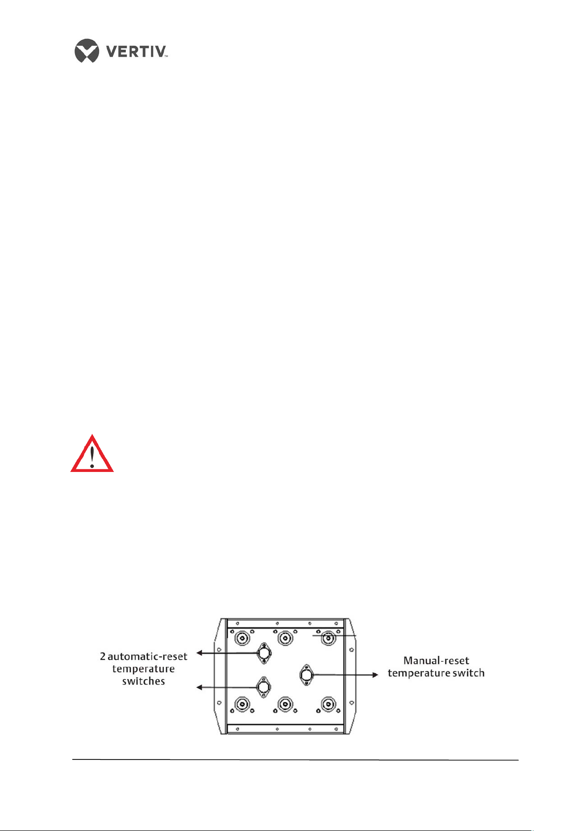
Vertiv I Liebert LPC I User Manual
5.6 Infrared Humidifier
Sedimentary material (such as mineral particles) accumulates on the water pan during the
operational flow. These sediments must be cleaned on a regular basis to ensure efficient
operation. However, the cleaning cycle varies because the quality of water differs from
region to region. Therefore, it is recommended to check and cleanse the water pan once a
month for optimal operation of the infrared humidifier. The auto-flush function of the
infrared humidifier can prolong the cleansing cycle. However, regular checks and
maintenance are mandatory from an operational point of view.
The following steps need to be implemented in the same hierarchy for maintenance and
inspection of the infrared humidifier:
1. Remove the water level standpipe to drain the water pan.
2. Disconnect the drainage pipe.
3. Remove the safety switch of the water pan.
4. Remove the fixing screws at both ends of the pan.
5. Pull out the water pan and clean it with water and a hard brush.
Once the water pan is cleaned, restore the water pan in the opposite sequence of steps
mentioned in the list, i.e. restore the water pan in its place and fix the fixing screws. Connect
the safety switch of the pan and connect the drainage pipe. Fix the water level standpipe to
complete the restoration process.
Prior to performing all the mentioned steps explained in the preceding list,
ensure that the power is cut off as it may lead to injury and fatality. The water in
the pan should be close to the room temperature before draining it from the
infrared humidifier to avoid personal injury.
5.7 Electric Heater
The Electrical heater contains three temperature switches that are serially connected to the
control loop. While two of the switches are automatic reset ones, the remaining one is a
manual reset switch.
Figure 5-1 shows a schematic representation of the three switches inside an electric heater:
Figure 5-1 Fin-tube type electric heater
83
Page 84

Vertiv I Liebert LPC I User Manual
The following steps need to be followed during inspection and maintenance of the
Electric heater:
• Check the rust on the electric heater. Use an iron brush to get rid of the rust, if possible
or replace it if the rustiness is immense or if there is some damage.
• When heating is required but heating is not effective or no heating effect is observed, a
multi- meter should be used to check whether the cable connected to the temperature
switch is functioning correctly to ensure that the three temperature switches are
normal.
• If the cable is not functioning properly, remove the electric heater and check if the
manual reset switch is disconnected. Next, check the automatic reset switches or the
electric heater pipe for damage or faulty condition.
5.8 Drainage check
When inspecting the drainage, check if there are no unwanted substances, debris, alien
objects, or particles in the water pan. Check the drainage for leakage too.
The check has to be conducted periodically on a regular basis.
84
Page 85

6 Appendix
6.1 Circuit Diag
Refer the attached drawing.
ram
Page 86

D
C
B
A
FACTORY MOUNTED MAIN UNIT SWITCH
SEE UNIT NAMEPLATE
FOR MAIN SUPPLY
WIRE SIZI NG
请查看机组铭牌
确定主电源线规
5
中
线
NEUTRAL
地
线
EARTH
10
SEE NOTE 6
见注意事项 6
15
SEE NOTE 7
见注意事项 7
COMMON
ALARM
CONNECT ION
20
公共报警端
EARTH GR OUND
CONNECT ION
接地端
子
25
30
35
40
45
50
55
60
65
出厂主隔离开关
LINE
VOLTAGE
3 PHASE
格
SUPPLY
三相线电压
EARTH GR OUND
接地端
.....
远程传感器
5
77
78
2RSB
2RSA
76
75
子
N
RC1,2
1,2
冷冷冷
ELECTRIC AL REHEAT
ELECTRIC AL REHEAT
CCH1
COMPRE SSOR NO.1
压缩机
1
CCH2
COMPRE SSOR NO.2
压缩机
2
INFRARE D HUMIDIFIE R
红外加湿器
HL1
HL2
HL2
HL3
MAIN FAN 1,2
主风机1,
2
源
子
.
(B)
(A)
(B)
(A)
CONNECT ION
远程传感器
7-1
7-2
89-1
89-2
9-1
9-2
9-3
电加热
电加热
Compresso r transduce r1
BK
BK
BK
BK
BK
BK
HL1
BK
HL2
BK
HL3
BK
2
1
R
R
R
2
R
R
R
压缩机驱动板1
U R
V S
W T
GND
12V
12V
GND
HS1
HS1-1
HS2
HS2-2
HS2-3
BK
BK
BK
L1
BK
L2
BK
L3
BK
BL
GN/Y
远程传感器
1
SEE NOTE 4
见注意事项
4
HEAT
REJECTIO N
DEVICE
CONNECT ION
连接冷凝器
控制回
路
SEE NOTE 8
见注意事项 8
SOLID STA TE RELAY
A B
1RSA
1RSB
HS1-3
HS2-4
HS2-1
SHADED ARE AS MAY BE FU SES
OR CIRCUIT BREAKERS
EMI FILTER
EMI滤波
1RSB
1RSA
12V
GND
82
83
A2 A1
B2 B1
C2 C1
固态继电器
6C1
1C1
2C1
3C1
6C2
1C2
2C2
3C2
5678
T1
24V
器
(B)
8-1
(A)
8-2
12V
69-1
GND
69-2
EM1
P
F1
BK
4-1
F2
BK
4-3
F3
BK
4-5
BK
4-7
POWER
INSPECT
L1L2L3
5-3
P
70
5C1
71
70A
5C2
71A
L1
L2
L3
BK
L1
L2
L3
BK
L1
L2
L3
1H1
1H2
2H2
( )
( )
L1
L2
L3
L1
L2
L3
阴影部分可以为保险
也可以为断路器
( )
丝
( )
11-1
12-1
12-5
11-3
12-7
12-3
13-1
13-5
16-1
14-1
14-3
13-3
13-7
17-1
17-7
17-3
17-5
16-3
F4
T2
24V
24V
F7
5-1
BK B K
BK BK
BK B K
BK BK
BK
BK
BK BK
BK
BK BK
4C1
BK BK
27-1
BK
27-3
4C2
BK BK
28-1
BK
28-3
ECF1
HWA
3H2
2H1
WUF
BK
50
56
55
SEE NOT E 3
注注注
注
3
37 38
BK
RSD
7-1
7-2
智能通信卡
69-1
69-2
F5
F6
ECF2
SDD
1BR
(OPTIONA L)
3-2
3-1
5-4
5-2
11-2
12-2
27-2B K
BK
BK
BKBK
12-6
11-4
28-2B K
12-8
12-4
BKBK
13-2
13-6
16-2
14-2
2451
14-4
13-4
13-8
17-2
17-8
17-4
17-6
16-4
5678
4
1-1
机组显示面
板
1-6
29-1
29-2
29-3
24V
BK
44-1
K3
18-3
K4
20-1
K6
20-3
K12
21-5
K11
21-4
K2
18-2
K10
21-3
K6
20-3
K5
20-2
K1
18-1
24V
K8
21-1
K9
21-2
1 2
EEVS2
2
EEV1
3
30-1
30-2
30-3
HP1
HP2
BK BK
DHV
BK
BK
H2
BK
H1
BK B KBKBK
HMV
BK
LLSV2
BK
LLSV1
BK
86-1
BK
BK
86-2
BK
BRBK
4321
1RSA
1RSB
2-6
2-7
2-3
81-1
81-2
81-3
(OPTIONA L)
1
PWR
4
EEV1
C1
C2
2EM1
SEE NOTE 5
见注意事项 5
SEE NOTE 5
见注意事项 5
SOLID STA TE RELAY
固态继电器
2BR
+
3BR
-
RS1 RS2 RS3
RS4 RS5 RS6
64-1
BK
64-2
BK
24-1
24-2
24-3
24-4
(OPTIONA L)
21Po
3
HS3
排气温度传感器
排气温度传感器
温湿度传感
BK
BK
BK
BK
器
82-1
82-2
82-3
1
3
G
2
BKBK
GN/Y
53
54
55GN/Y
58GN/Y
SEE NOTE 3
见注意事项 3
BKBK
1EM1
ECFAN
/EC风机
E1/Ain
GND
ECF1,2
1
2
4
23
NOTES/注意事项:
1. ALL FIELD WIRING TO BE PER LOCAL CODES. USE COPPER CONDUCTORS ONLY.
所有现场配线请依照当地标准,最好使用铜线。
2. SEE INSTALLATION AND USER MANUAL(S).
3. JUMPER TO BE REMOVED WHEN O PTIONAL COMPONENT IS USED.
当使用选配组件时,请去掉短接线
4. OPTIONAL EMERGENCY POWER L OCKOUT OF REHEAT AND/OR HUMIDIFIER:
CONNECTIONS PROVIDED FOR REMOTE 24V AC SOURCE.
选配紧急电源锁死可用于加热和加湿:接线用于远端提供24V交流电源。
5. LLSV IS ONLY OPTIONAL FOR L ONG PIPE APPLICATION AS ONE OF THE
5
COMPONENTS OF EXTENSION KITS.
液管电磁阀是长配管延长组件之一,非标选配。
6. ON UNITS WITH NO SIC CARD,CON NECTION 485 OF PLUGS 7-1 AND 7-2 TO
ALTERNATE CONNECTIONS AT SCREW TERMINALS 77 AND 78.
机组无SIC卡时, J7-1 和 J7-2 的485接口连接到端子77和78处
7. TERMINALS ONLY FOR FACTORY S UPPLIED.
8. A DUAL HEAT REJECTION DIVICE APPLY TO DOUBLE SYS UNITS,NEED TO
CONNECT 70 TO 70A AND TO CONNECT 71 TO 71A.TERMINAL 70 AND 71
ARE USED OR 70A AND 71A ARE USED.
如双系统冷凝器用于双系统机组,70和70A短接
10
71和71A短接,控制回路可从70和71接线,或从70A和71A接线。
。
1
请看安装和使用手册
工厂专用端子。
,
15
NOMENCLATUR E /
说
说
STANDARDDEVICES/ 标准设备
BR - BACKUP REHEAT RELAY
/电加热辅助继电器
C1 - COMPRESSOR CONTACTOR
/1号压缩机接触器
20
C2 - COMPRESSOR CONTACTOR
/2号压缩机接触
CCH1,2 - CRANKCASE HEATER NO.1,2
/曲轴箱1,2加热
DLTS1,2 - DISCHARGE LINE
TEMPERATURE SENSOR 1,2
/排气温度传感器1,2
除湿电磁阀
H1,2 - HUMIDIFIER CONTACTOR1,2
/加湿器接触器1,
25
HMV - HUMIDIFIER MAKE-UP VALVE
/加湿器注水阀
HP1,2 - HIGH PRES SURE SWITC H
NO.1, 2
HS1,2 - MANUAL RESET TEMPERATUR
-E SAFETY SWITCH1,2
/手动复位温度安全开关1,2
HS3 - MANUAL RESET HUMIDIFIER
SAFETY(UNDER PAN)
/加湿防干烧温度继电器(水盘底部
30
HU - HUMIDITY SENSOR
HWA - HIGH WATER ALARM
/高水位报
K1 - MAIN FAN RELAY
K2 - HUMIDIFICATION RELAY
/加湿继电
器
K3,4 - COMPRESSOR NO.1,2 RELAY
/1,2号压缩机继电器
K8,9 - REHEAT STAGE 1,2 RELAY
/1,2级加热继电
K10 - HUMIDIFIER MAKE-UP RELAY
35
/加湿注水继电
K11 - HUMIDIFICATION RELAY
/加湿继电
器
RS1,2,3 - REHEAT 1 SAFETY STATS
/1级电加热过热保护继电器
SCR - SOLID STATE RELAY
/电加热固态继电器
TH - TEMPERATURE/HUMIDITY
SENSOR
40
45
K
50
55
/橙色
/红色
/棕色
/紫色
/绿色
60
配线色标只起指导作
配线线号根据实际选
65
本文件之版权属
艾默生网络能源有限公司所有
未经书面批准,不得随意复制
23
2
/高压开关
警
/温度传感
注
LINE
STANDARDDEVICES/ 标准设备
行
50
T1 - UNIT CONTROL TRANSFORMER
/机组控制变压
20
T2 - ISOLATION TRANSFORMER
/隔离变压
器
21
36,47
61,65
26
35,32
39
20,21
56
58
)
3
/湿度传感
器
35
46
RS4,5,6 - REHEAT 1 SAFETY STATS
35
RSD - REMOTE SHUTDOWN DEVICE
(75VA MIN. RA TING)
20,26
50,55
SDD - SMOKE DETECTOR DEVICE
39
WUF - WATER UNDER FLOOR
26
50
30,47
3
WIRING LEGE ND /
/黄色
/蓝色
/黑色
/白色
TITLE
用
取
DRAWING NO REV
,
!
EEV1 - ELECTRONIC EXPANSION
VALVE 1
P1 - PRESSURE SENSOR1
/压力传感器1
TS1 - TEMPERATURE SENSOR 1
/温度传感器1
OPTIONALDEVICES / 选配设
EM1 - EMERGENCY POWER
LOCKOUT RELAY
/紧急电源锁死继电
LLSV1,2 - LIQUID LINE SOLENOID 1,2
/液管电磁阀1,2
2级电加热过热保护继电器
/远程报警装置(至少为75VA
/烟感开关
SIC - SMART INTELLISLOT CARD
/智能通信
卡
/地板溢水开关
线
线
V
29043391
器
带
1
/主风机继电器
器
器
器
FACTORY SUPPLIED LINE VOLTAGE WIRING/出厂线电压线
FIELD SUPPLIED LINE VOLTAGE WIRING/现场线电压配
VOLTAGE WIRINGIN OPTIONS/选配线电压线
FACTORY SUPPLIED 24 VOLT WIRING/出厂24V线路
FIELD SUPPLIED 24 VOLT WIRING/现场24V配线
CONTROL BOARD INTERNAL WIRING-24VOLTMAX
/ 控制板内部线路-最大电压值24
WIRING AND DEVICES INCLUDED INOPTIONS/选配设备及线路
ELECTRONIC SWITCH (RELAY) K1-K12 / 电子开关(继电器)K1-K1
INLINE QUICK DISCONNECT/线上快速对插端
INLINE BLOCK DISCONNECT/线上块状接线端
OPEN CONTROL BOARD CONNECTION/控制板无源节点
PLUG CONNECTION ONCONTROLBOARD/控制板上插线端子
TERMINAL STRIP CONNECTION FOR FIELD WIRING/现场配线端子
TERMINAL BLOCK CONNECTION ONCONTROLBOAR
/控制板上块状接线端子
CIRCUIT CONNECTION TO ELECTRONICS/有源节
GROUND CURRENT DETECTOR CIRCUIT /接地电流检测电路
PLUG CONNECTION ON VSC BOARD /风机调速板上插线端
意
1
。
。
器
/电子膨胀阀1
路
子
子
D
点
D
LINE
行
2
9
65,13
12
61
C
LINE
备
行
13
器
43,44
53
63
)
50
4
44
B
路
线
2
子
A
A01
 Loading...