

Page 1

Liebert®
Load Bus Sync™ Controller for Liebert® NX™ 225-600kVA UPS
User Manual
Page 2

The information contained in this document is subject to change
without notice and may not be suitable for all applications. While
every precaution has been taken to ensure the accuracy and
completeness of this document, Vertiv assumes no responsibility
and disclaims all liability for damages resulting from use of this
information or for any errors or omissions. Refer to other local
practices or building codes as applicable for the correct methods,
tools, and materials to be used in performing procedures not
specifically described in this document.
The products covered by this instruction manual are manufactured
and/or sold by Vertiv This document is the property of Vertiv and
contains confidential and proprietary information owned by Vertiv.
Any copying, use or disclosure of it without the written permission of
Vertiv is strictly prohibited.
Names of companies and products are trademarks or registered
trademarks of the respective companies. Any questions regarding
usage of trademark names should be directed to the original
manufacturer.
Technical Support Site
If you encounter any installation or operational issues with your product, check the pertinent
section of this manual to see if the issue can be resolved by following outlined procedures.
Visit https://www.VertivCo.com/en-us/support/ for additional assistance.
Page 3

TABLE OF CONTENTS
IMPORTANT SAFETY INSTRUCTIONS . . . . . . . . . . . . . . . . . . . . . . . . . . . . . . . . . . . . . . 1
SAVE THESE INSTRUCTIONS . . . . . . . . . . . . . . . . . . . . . . . . . . . . . . . . . . . . . . . . . . . . . . . 1
1.0 INTRODUCTION. . . . . . . . . . . . . . . . . . . . . . . . . . . . . . . . . . . . . . . . . . . . . . . . . . . . . . . 2
1.1 Installation Kit - 10B14515G1 . . . . . . . . . . . . . . . . . . . . . . . . . . . . . . . . . . . . . . . . . . . . . . . . . . . . . . . . . . . . . 2
1.2 Mechanical Characteristics . . . . . . . . . . . . . . . . . . . . . . . . . . . . . . . . . . . . . . . . . . . . . . . . . . . . . . . . . . . . . . 3
2.0 TYPICAL CONFIGURATIONS . . . . . . . . . . . . . . . . . . . . . . . . . . . . . . . . . . . . . . . . . . 5
2.1 Two Systems with Separate Utility Supplies. . . . . . . . . . . . . . . . . . . . . . . . . . . . . . . . . . . . . . . . . . . . . 5
2.2 Two UPS Units With Common Bypass Line . . . . . . . . . . . . . . . . . . . . . . . . . . . . . . . . . . . . . . . . . . . . . . 6
2.3 Liebert® Systems and Electrical Generating Devices . . . . . . . . . . . . . . . . . . . . . . . . . . . . . . . . . . . . 6
2.4 Liebert® NX™ and Third-Party Brand UPS in the Same Installation. . . . . . . . . . . . . . . . . . . . . . 8
3.0 INSTALLATION. . . . . . . . . . . . . . . . . . . . . . . . . . . . . . . . . . . . . . . . . . . . . . . . . . . . . . . 10
3.1 Installation Kit - 10B14515G1 . . . . . . . . . . . . . . . . . . . . . . . . . . . . . . . . . . . . . . . . . . . . . . . . . . . . . . . . . . . . 10
3.2 Installation Tips. . . . . . . . . . . . . . . . . . . . . . . . . . . . . . . . . . . . . . . . . . . . . . . . . . . . . . . . . . . . . . . . . . . . . . . . . 10
3.3 Appendix C - Liebert® NX™ 225-600kVA . . . . . . . . . . . . . . . . . . . . . . . . . . . . . . . . . . . . . . . . . . . . . . . 10
3.3.1 Setting Parameters - Enable External Synchronization Control . . . . . . . . . . . . . . . . . . . . . . . . . 10
3.3.2 Offset Compensation Tuning. . . . . . . . . . . . . . . . . . . . . . . . . . . . . . . . . . . . . . . . . . . . . . . . . . . . . . . . . . . . 12
3.3.3 Procedure complete for UPS1 . . . . . . . . . . . . . . . . . . . . . . . . . . . . . . . . . . . . . . . . . . . . . . . . . . . . . . . . . . . 14
3.4 Installation Example . . . . . . . . . . . . . . . . . . . . . . . . . . . . . . . . . . . . . . . . . . . . . . . . . . . . . . . . . . . . . . . . . . . . 15
FIGURES
Figure 1 Rear panel reference supply input . . . . . . . . . . . . . . . . . . . . . . . . . . . . . . . . . . . . . . . . . . . . . . . . . . . 3
Figure 2 Front panel UPS sync. outputs . . . . . . . . . . . . . . . . . . . . . . . . . . . . . . . . . . . . . . . . . . . . . . . . . . . . . . . 4
Figure 3 Two separate utility supplies. . . . . . . . . . . . . . . . . . . . . . . . . . . . . . . . . . . . . . . . . . . . . . . . . . . . . . . . . 5
Figure 4 Common bypass line . . . . . . . . . . . . . . . . . . . . . . . . . . . . . . . . . . . . . . . . . . . . . . . . . . . . . . . . . . . . . . . . . 6
Figure 5 Liebert® NX™ systems and electrical generating devices . . . . . . . . . . . . . . . . . . . . . . . . . . . . 7
Figure 6 Liebert® NX™ and third-party brand UPS . . . . . . . . . . . . . . . . . . . . . . . . . . . . . . . . . . . . . . . . . . . . 8
Figure 7 Installation example . . . . . . . . . . . . . . . . . . . . . . . . . . . . . . . . . . . . . . . . . . . . . . . . . . . . . . . . . . . . . . . . . .9
Figure 8 Offset compensation . . . . . . . . . . . . . . . . . . . . . . . . . . . . . . . . . . . . . . . . . . . . . . . . . . . . . . . . . . . . . . . . 12
Figure 9 Synchro Error 88,56 [°] . . . . . . . . . . . . . . . . . . . . . . . . . . . . . . . . . . . . . . . . . . . . . . . . . . . . . . . . . . . . . . 12
Figure 10 Synchro Error 0 [°] . . . . . . . . . . . . . . . . . . . . . . . . . . . . . . . . . . . . . . . . . . . . . . . . . . . . . . . . . . . . . . . . . . 13
Figure 11 Installation example . . . . . . . . . . . . . . . . . . . . . . . . . . . . . . . . . . . . . . . . . . . . . . . . . . . . . . . . . . . . . . . . . 15
TAB LES
Table 1 Installation Kit - 10B14515G1 components. . . . . . . . . . . . . . . . . . . . . . . . . . . . . . . . . . . . . . . . . . . . 2
Table 2 Electrical Characteristics. . . . . . . . . . . . . . . . . . . . . . . . . . . . . . . . . . . . . . . . . . . . . . . . . . . . . . . . . . . . . 3
Table 3 Installation Kit - 10B14515G1 components. . . . . . . . . . . . . . . . . . . . . . . . . . . . . . . . . . . . . . . . . . . 10
Vertiv™ |Liebert® Load Bus Sync™ Controller Installation Manual | i
Page 4

Vertiv™|Liebert® Load Bus Sync™ Controller Installation Manual | ii
Page 5

IMPORTANT SAFETY INSTRUCTIONS
SAVE THESE INSTRUCTIONS
This manual contains important instructions that should be followed during installation of your
Liebert® Load Bus Sync™ Controller. The Liebert® Load Bus Sync™ installation must be performed
only by properly trained and qualified personnel.
Read this manual thoroughly, paying special attention to the sections that apply to your
installation, before working with the UPS. Retain this manual for use by installing personnel.
Before beginning to install the Liebert® Load Bus Sync™ Controller verify that:
®
• The Liebert
indicators are extinguished)
• The UPS and the Liebert
remote power supplies.
• All power supplies upstream of the UPS are switched Off. Should the UPS be switched On, carry out the
shutdown procedure as described in the unit’s user manual.
™
NX
UPS and the Liebert® Load Bus Sync™ Controller are switched Off (all front-panel
®
Load Bus Sync™ Controller and related installations are isolated from all local and
WARNING
Risk of electric shock. Can cause injury and death.
Under typical operation and with all UPS doors closed, only normal safety precautions are
necessary. The area around the UPS system should be kept free of puddles of water, excess
moisture and debris.
Special safety precautions are required for procedures involving handling, installation and
maintenance of the UPS system and the batteries. Observe all safety precautions in this
manual before handling or installing the UPS system. Observe all precautions in this
manual, before as well as during performance of all maintenance procedures. Observe all
battery safety precautions before working on or near the battery.
This equipment contains circuits that are energized with high voltage. Only test equipment
designed for troubleshooting should be used. This is particularly true for oscilloscopes.
Always check with an AC and DC voltmeter to ensure safety before making contact or
using tools. Even when the power is turned Off, dangerously high electric charges may exist
within the UPS or Liebert
All power and control wiring should be installed by a qualified electrician. All power and
control wiring must comply with the NEC and applicable local codes.
ONLY qualified service personnel should perform maintenance on the UPS system. When
performing maintenance with any part of the equipment under power, service personnel
and test equipment should be standing on rubber mats. The service personnel should wear
insulating shoes for isolation from direct contact with the floor (earth ground).
Never work alone, even if all power is removed from the equipment. A second person
should be standing by to assist and summon help in case an accident should occur.
®
Load Bus Sync™ Controller.
NOTICE
Risk of improper electromagnetic shielding. Can cause radio communication interference.
This unit complies with the limits for a Class A digital device, pursuant to Part 15 Subpart J of the FCC
rules. These limits provide reasonable protection against harmful interference in a commercial
environment. This unit generates, uses and radiates radio frequency energy and, if not installed and used
in accordance with this instruction manual, may cause harmful interference to radio communications.
This unit is not designed for use in a residential area. Operation of this unit in a residential area may cause
harmful interference that the user must correct at his own expense.
Vertiv™ |Liebert® Load Bus Sync™ Controller Installation Manual | 1
Page 6

1.0 INTRODUCTION
The Liebert® Load Bus Sync™ Controller is an option designed for use in complex power source
systems consisting of different distributions and static switches supplied by Vertiv™ and other
manufacturers. It provides synchronization between the Liebert® NX™ 225-600V and third-party
UPS systems when synchronization cannot be guaranteed by the system configuration or when
temporary conditions prevent it (e.g., during battery operation).
The Liebert® Load Bus Sync™ Controller is available as an option with the Liebert® NX™ 225-600V,
either as a factory-installed option or as a kit that is installed and configured by Vertiv™-trained
and certified personnel.
Examples of configurations where the Liebert® Load Bus Sync™ Controller can be used:
• Installation consisting of two Liebert® NX™ 225-600V units
• Installation consisting of a Liebert
• Installation consisting of a Liebert
The Liebert® Load Bus Sync™ Controller option consists of an electronic unit housed in a metal
box that can be mounted near the UPS or inside the electrical distribution panel.
The Liebert® Load Bus Sync™ Controller requires a 480V input reference supply and can be used
to supply two units. When installing the unit inside a distribution panel or UPS, ensure that the
metal box is secured so that it cannot fall or touch metal parts containing hazardous voltages.
Vertiv™ recommends that the unit not be installed behind the second access panel or in front of
the Liebert® NX™ air inlet vents.
®
NX™ 225-600V and electrical generating devices
®
NX™ 225-600V and third-party UPS systems.
The device operates by identifying one of the connected units as the master and using its
frequency as a reference for the other units (slaves). While a non-Liebert® UPS can be used as
the master, only Liebert® UPS’s can be used as slave units. Depending on their configuration, the
slave units will follow the reference frequency all the time, or only when their reserve utility supply
is out of tolerance. The reference frequency will be generated only when the master utility supply
line is within acceptable limits.
The Liebert® Load Bus Sync™ Controller can drive up to two separate units. These units may be
independent of each other or connected in a parallel system. Where the installation consists of
more than two slave units, or the master/slave configuration is not the preferred option, Vertiv™
suggests using Liebert® MultiBus Synchronization Module™ (MBSM), Part No. 10B14545G1.
The Liebert® Load Bus Sync™ Controller does not affect the system’s mean time between failure
(MTBF)—it is not a single point of failure for the system). The individual units will ignore this
signal if it is outside the acceptable limits.
1.1 Installation Kit - 10B14515G1
The equipment is supplied with the following components:
Table 1 Installation Kit - 10B14515G1 components
Item
Description Part #
1 Circuit Board 10B10877G1 1
2 Metal Enclosure — 1
3 RJ-45 Short Cable 10H54910P15 1
4 Installation Manual 10H92873 1
5 Female IEC 10 A plug 10H46776P01/02 1
Quantity
Vertiv™ |Liebert® Load Bus Sync™ Controller Installation Manual | 2
Page 7
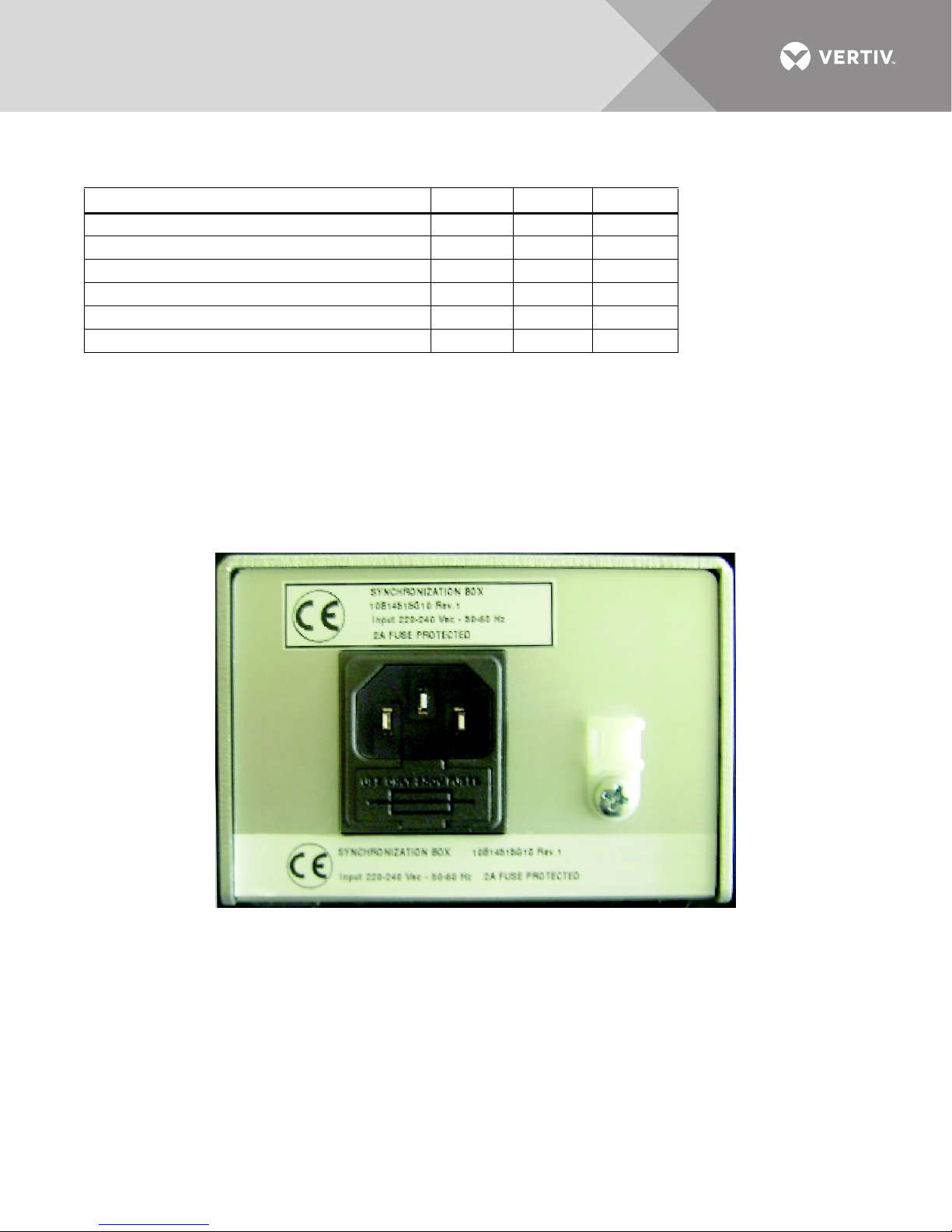
The Liebert® Load Bus Sync™ Controller has the electrical characteristics detailed in Tab le 2.
Table 2 Electrical Characteristics
Minimum Nominal Maximum
Supply voltage (50/60 Hz sinusoidal), volts 180 480 250
Supply current, mA — 14 —
Output current (per channel), mA 25 — 30
Working temperature °F (°C) 14 (-10) — 104 (40)
Phase stability error — 0.18 —
Phase shift within voltage tolerance range, degrees * — 1.5 °
* Voltage within ±10% of nominal value.
1.2 Mechanical Characteristics
The Liebert® Load Bus Sync™ Controller has these dimensions:
• Length = 7.1" (181mm)
• Width = 3.7" (94mm)
• Height = 2.5" (64mm)
Figure 1 Rear panel reference supply input
Vertiv™ |Liebert® Load Bus Sync™ Controller Installation Manual | 3
Page 8
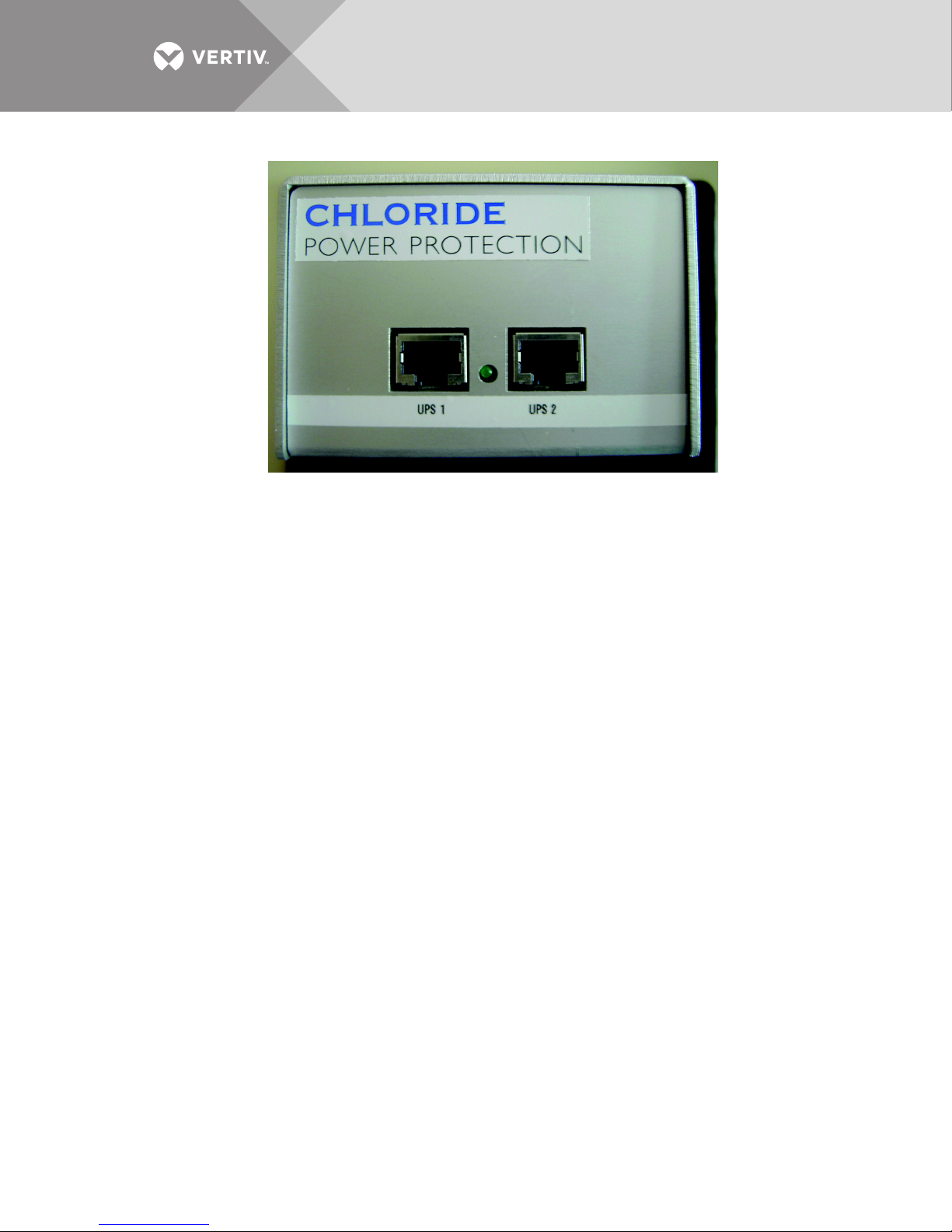
Figure 2 Front panel UPS sync. outputs
Vertiv™ |Liebert® Load Bus Sync™ Controller Installation Manual | 4
Page 9
2.0 TYPICAL CONFIGURATIONS
Power Source A Power Source B
SlaveMaster
UPS A UPS B
Source
Line B
Source
Line A
Static Switch
To Others
Static Switch
To Load
To Others
Static Switch
Liebert®Load
Bus Sync
™
Controller
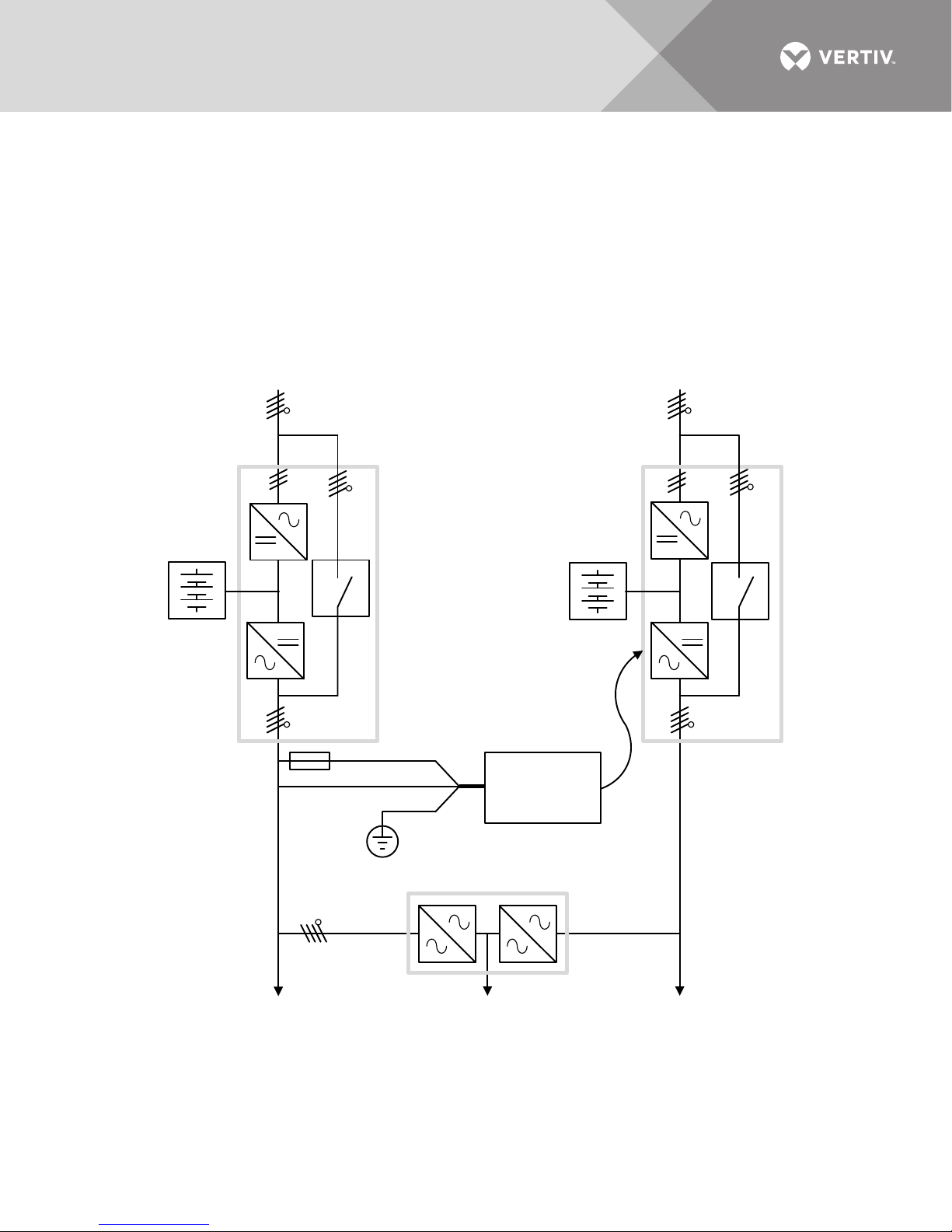
2.1 Two Systems with Separate Utility Supplies
When two UPS’s are connected to separate power sources, the inverters attempt to synchronize
with their respective bypass lines, but the lines may not be in phase, so synchronization cannot be
guaranteed. Even if the two units are supplied from a common line, when one or both is operating
on-battery there will be no common input signal, and the outputs will not be synchronized. When
the Liebert® Load Bus Sync™ Controller is installed, one of the UPS outputs must be chosen as the
master, all the other UPS (slave) outputs will then follow this reference: see Figure 3 for details.
Figure 3 Two separate utility supplies
N.B. fuses should be installed in the phase signal line, upstream of the Liebert® Load Bus Sync™
Controller to protect against the damage caused by short circuits. Installation tips: UPS B should
be configured so that it follows the external synchronization signal. This is achieved by setting
the main synchronization source to external signal. Otherwise, the UPS will be in phase with its
own bypass line and will follow external synchronization only when this is out of tolerance.
Vertiv™ |Liebert® Load Bus Sync™ Controller Installation Manual | 5
Page 10
2.2 Two UPS Units With Common Bypass Line
Power
Source B
UPS B
Power
Source A
UPS A
Source
Line B
Source
Line A
UPS A
L1 -Phase S ignal
Neutral
L1 -Phase Signal
Common Bypas s
Line
Static Switch
To Load
To Others
Static Switch
UPS
B
To Others
Static Switch
Liebert®Load Bus
Sync
™
Controller
Liebert®Load Bus
Sync
™
Controller
Slave
Master
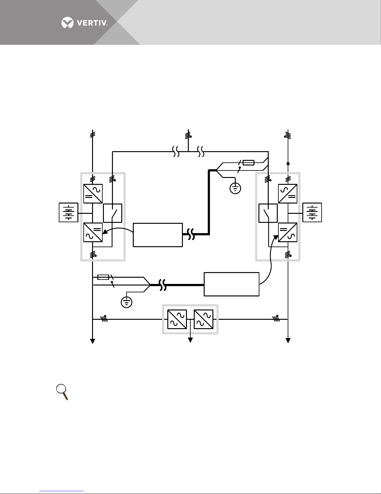
When two UPS’s are connected with a common bypass line, the bypass line synchronizes the two
inverters. Synchronization can be lost because of protection upstream of the bypass line. Using
the following solution, the two systems will be always synchronized, even if one of the two bypass
lines is out of tolerance. These units will usually be capable of synchronous operation.
Figure 4 Common bypass line
N.B. fuses should be connected at the beginning of the signal line to avoid fires in case of short
circuit in the wires.
NOTE
UPS A and UPS B should be configured with main synchronization source to bypass. Otherwise
2.3 Liebert® Systems and Electrical Generating Devices
The Liebert® Load Bus Sync™ Controller can be used to provide phase reference to the Liebert®
NX™ UPS in installations with alternative power sources, such as diesel generators, see Figure 5.
the UPS’s won’t be capable of synchronous transfer to bypass.
Vertiv™ |Liebert® Load Bus Sync™ Controller Installation Manual | 6
Page 11
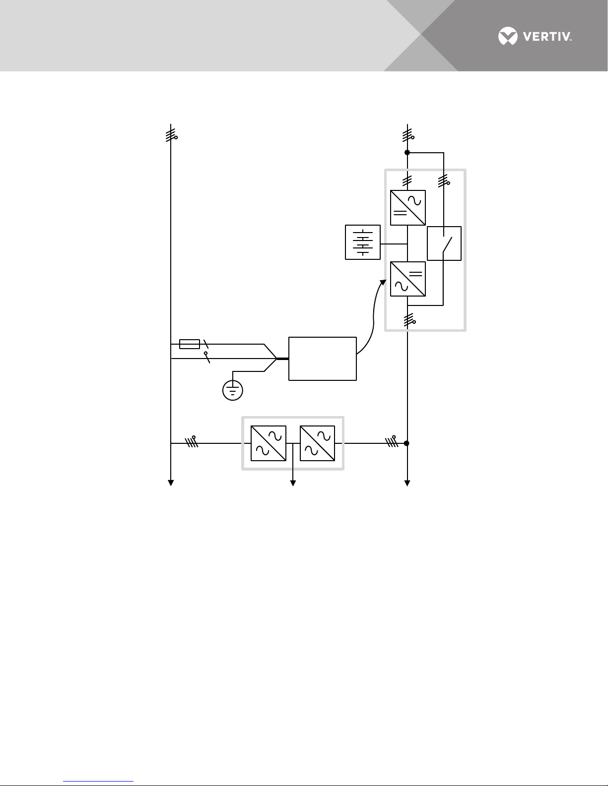
Figure 5 Liebert® NX™ systems and electrical generating devices
Source
Line B
Source
Line A
Power Source
UPS
Liebert®Load
Bus Sync
™
Controller
Static Switch
To Load
Master Power Source
L1 -Phase Signal
Neutral
To Others
Static Switch
To Others
Static Switch
N.B. fuses should be installed in the phase signal line, upstream of the Liebert® Load Bus Sync™
Controller, to protect against the damage caused by short circuits.
Vertiv™ |Liebert® Load Bus Sync™ Controller Installation Manual | 7
Page 12
2.4 Liebert® NX™ and Third-Party Brand UPS in the Same Installation
Source
Line B
Source
Line A
Power
Source B 2
UPS 2
Power
Source B1
UPS 1
To Load
To Others
Static Switch
Power
Source A
UPS 1
UPS 2
L1 -Phase Signal
Neutral
To Others
Static Switch
Static Switch
Liebert®Load
Bus Sync
™
Controller
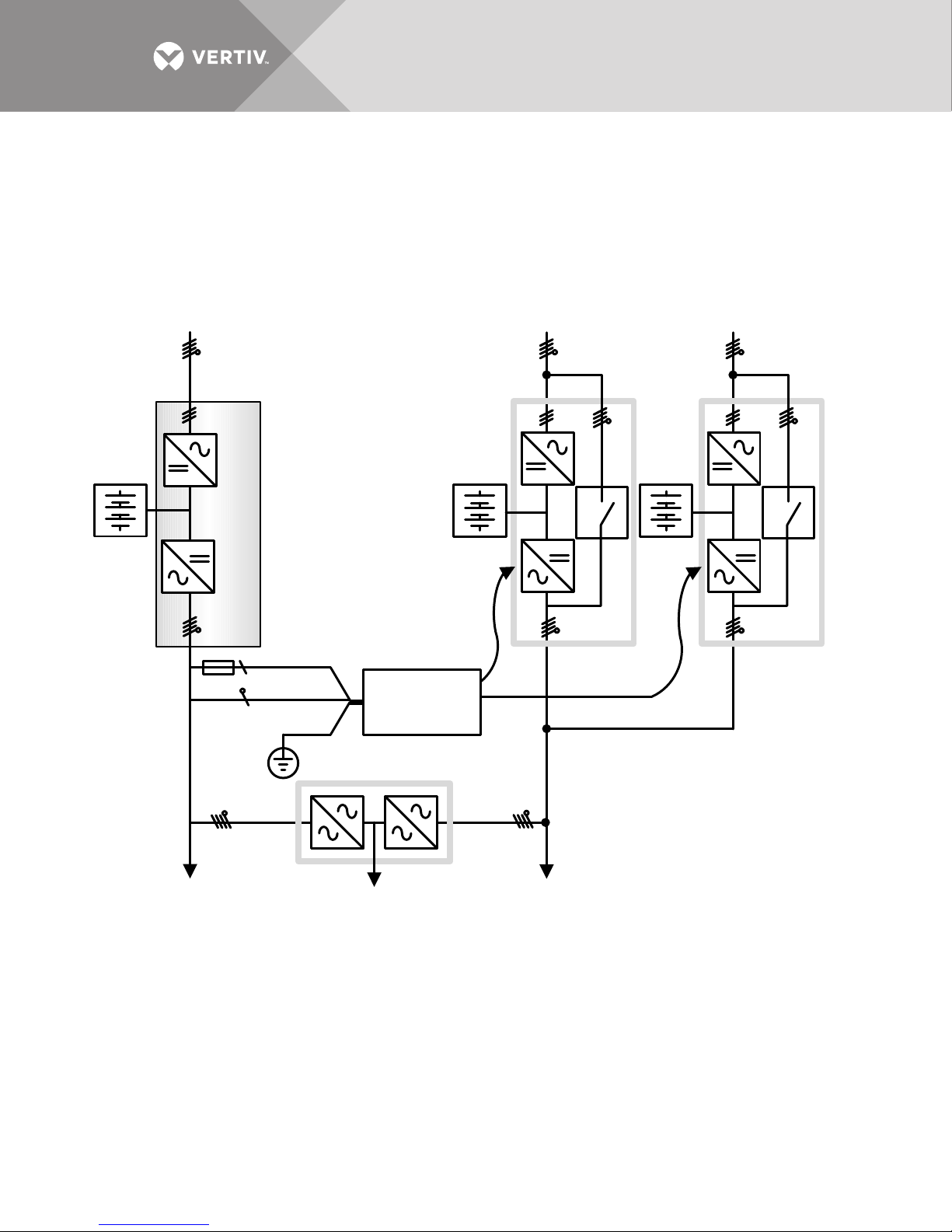
The device can also be used to synchronize a Liebert® NX™ UPS with other manufacturer’s UPS
systems. The Liebert® NX™ units must be configured as slave devices so that they follow the phase
reference signal derived from the non-Liebert® master UPS. UPS #1 and UPS #2 may be
configured as parallel or single units, see Figure 6.
Figure 6 Liebert® NX™ and third-party brand UPS
Installation Tips: UPS #1 and UPS #2 should be configured to follow the external
synchronization signal. This is achieved by setting the main synchronization source to external
signal. If UPS #1 and UPS #2 are not set to follow the external synchronization signal, the UPS will
be in phase with its own bypass line and will follow external synchronization only when the bypass
line is out of tolerance.
Vertiv™ |Liebert® Load Bus Sync™ Controller Installation Manual | 8
Page 13
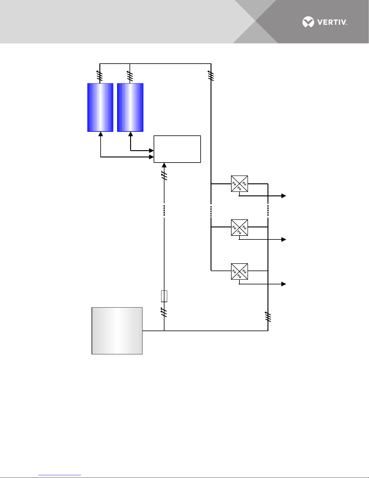
Figure 7 Installation example
Third-Party
UPS
(not by
Vertiv
™
)
Liebert®Load
Bus Sync
™
Controller
Liebert
®NX™
UPS Parallel
System
Short connection
between UPS’s and
Liebert
®
Load Bus
Sync
™
Controller
Long connection between
Master source and
Liebert
®
Load Bus Sync
™
Controller
Fuse
Floor 1
Supply
Floor 2
Supply
Floor X
Supply
Vertiv™ |Liebert® Load Bus Sync™ Controller Installation Manual | 9
Page 14
3.0 INSTALLATION
3.1 Installation Kit - 10B14515G1
The equipment is supplied with the following components:
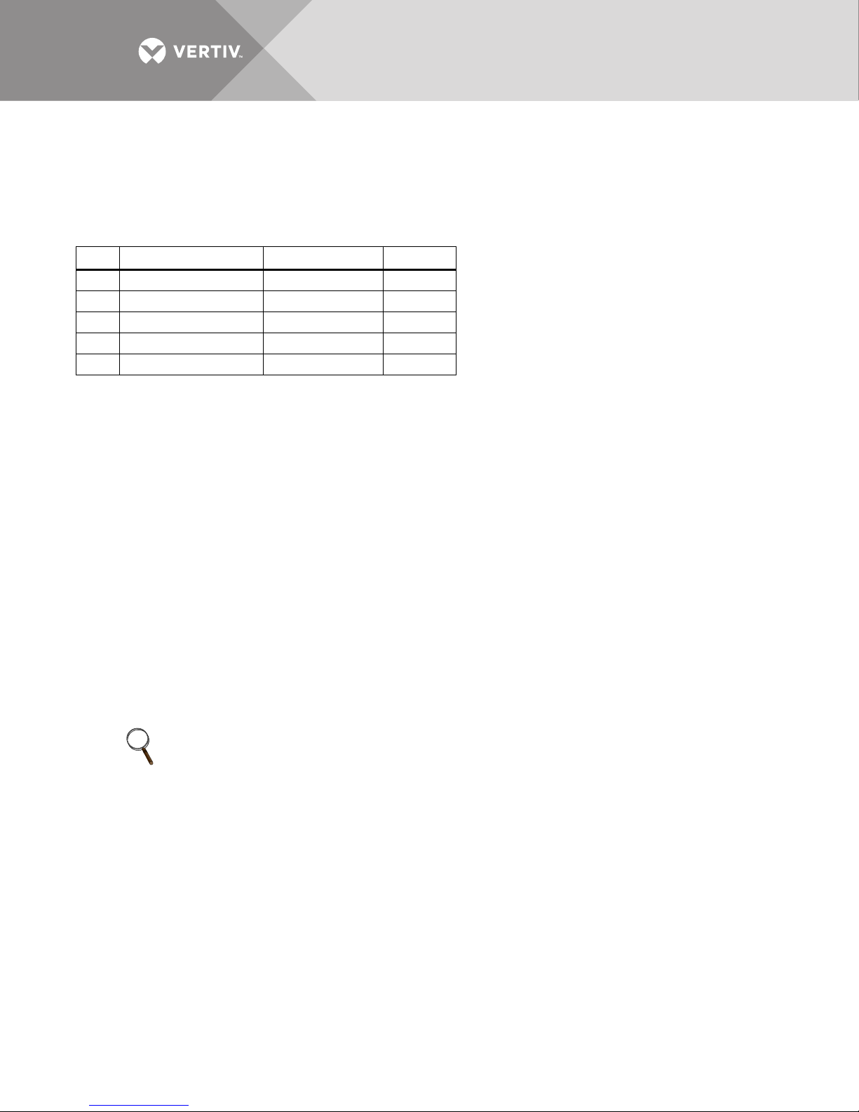
Table 3 Installation Kit - 10B14515G1 components
Item
Description Part #
1 Circuit Board 10B10877G1 1
2 Metal Enclosure — 1
3 RJ-45 Short Cable 10H54910P15 1
4 Installation Manual 10H92873 1
5 Female IEC 10 A plug 10H46776P01/02 1
Connect the PE, and master phase and neutral signals to the Liebert® Load Bus Sync™ Controller
reference signal input (see Figure 1) using the female IEC 10 A plug and a suitable power cable.
Connect the slave UPS to the Liebert® Load Bus Sync™ Controller UPS output (see Figure 2)
using the RJ-45 short cable.
3.2 Installation Tips
• Connect the Liebert® Load Bus Sync™ Controller input earth cable to a protective earth terminal.
• Position the Liebert
• Use shielded RJ-45 cables.
• Connect the RJ-45 cable (10H54910P15) directly to the control board; do not use terminals to extend
connections.
• Position the Liebert
such as: vibration, dust, corrosive atmospheres and high humidity.
• Install a 2A slow-blow fuse on the phase signal line as close as possible to the master unit
• If the Liebert
®
®
Load Bus Sync™ Controller near the slave units.
®
Load Bus Sync™ Controller in a suitable location, protected from harmful conditions
Load Bus Sync™ is mounted on top of a UPS, ensure that it does not obstruct air outlets.
Quantity
NOTICE
Risk of improper electrical connections. Can cause equipment damage.
The Liebert
®
Load Bus Sync™ Controller must be supplied from L1 and N.
NOTE
Once the connections above have been completed, follow the procedure related to the UPS
model in 3.3 - Appendix C - Liebert® NX™ 225-600kVA
3.3 Appendix C - Liebert® NX™ 225-600kVA
3.3.1 Setting Parameters - Enable External Synchronization Control
Once all connections are completed, switch on QS1 on the first UPS and set the following
parameters:
1. In PPVis, click on “Service Tools” and select “Parameter.”
2. Set “Access level” to “Superservice”: PNU 51=4.
3. Set “Function Selection” to “HW-In it”: PNU 52=2.
4. Set “External synchronization control” to “Enable:” PNU 700=1.
5. Set “Function selection” back to “Return”: PNU 52=0.
6. Set “Access level” back to “Normal operation:” PNU 51=1.
7. Once back in normal operation, open QS1 and the electronics will shut down.
Vertiv™ |Liebert® Load Bus Sync™ Controller Installation Manual | 10
Page 15
Follow these steps for ALL the units connected to the Liebert® Load Bus Sync™ Controller.
NOTE
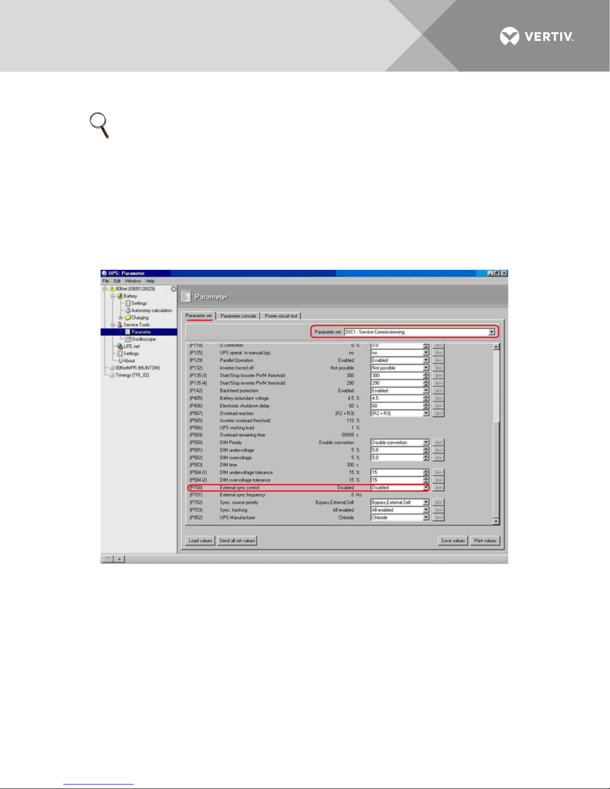
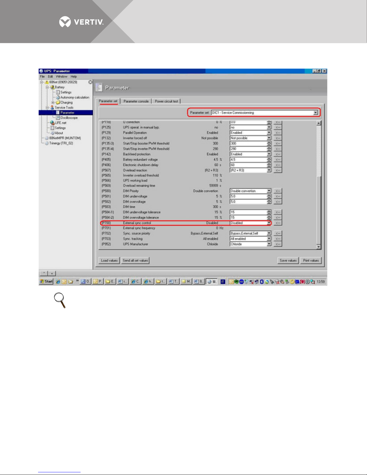
Since the DIC FW Rev. 1.10 users may change parameters through a graphic interface:
1. In this case in PPVis click on “Service Tools” and select “Parameter” -> “Parameter set” -> “DIC1 - Service
commissioning”
2. Set PNU 51 “Access level” to “Superservice(4).”
3. Set PNU 52 “Function Selection” to “HW-Init(2).”
4. Set PNU 700 “External synchronization control” to “Enable(1).”
5. Set PNU 52 “Function selection” back to “Return(0).”
6. Set PNU 51 “Access level” back to “Normal operation(1).”
7. Click on “Send all set values” push button.”
8. Once back in normal operation open QS1 and the electronics will shut down.
Vertiv™ |Liebert® Load Bus Sync™ Controller Installation Manual | 11
Page 16
3.3.2 Offset Compensation Tuning
Main Bus A
CH1
Oscilloscope
CH2
Fref
Liebert
®
Load Bus
Sync™
Reserve Input
UPS An
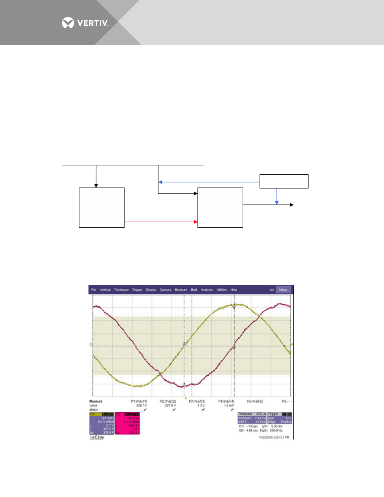
The parameter 731.32 has been designed to compensate the phase error, introduced by the UPS
control, between the frequency reference coming from the Liebert® Load Bus Sync™ Controller
and the inverter output signal. To carry out this procedure an oscilloscope between reserve input
and inverter output must be used. The Liebert® Load Bus Sync™ Controller must be installed and
interconnected to the UPS system. The PNU 700 must be set to 1. The PNU 731.32 calibration
must be done on each UPS in the system. Perform the following steps:
1. Connect an oscilloscope to the first UPS.
Connect “Channel 1" to “Bypass Input L1 and N” and “Channel 2" to “UPS Output L1 and N”, as shown in
Figure 8) Main BUS A.
Figure 8 Offset compensation
2. With NO LOAD connected, start the inverter.
3. Open the reserve input switch QS2.
4. Verify on the oscilloscope the phase error between inverter and bypass. The following figures show an
example of NO SYNC (Figure 9) and SYNC (Figure 10).
Figure 9 Synchro Error 88,56 [°]
Vertiv™ |Liebert® Load Bus Sync™ Controller Installation Manual | 12
Page 17
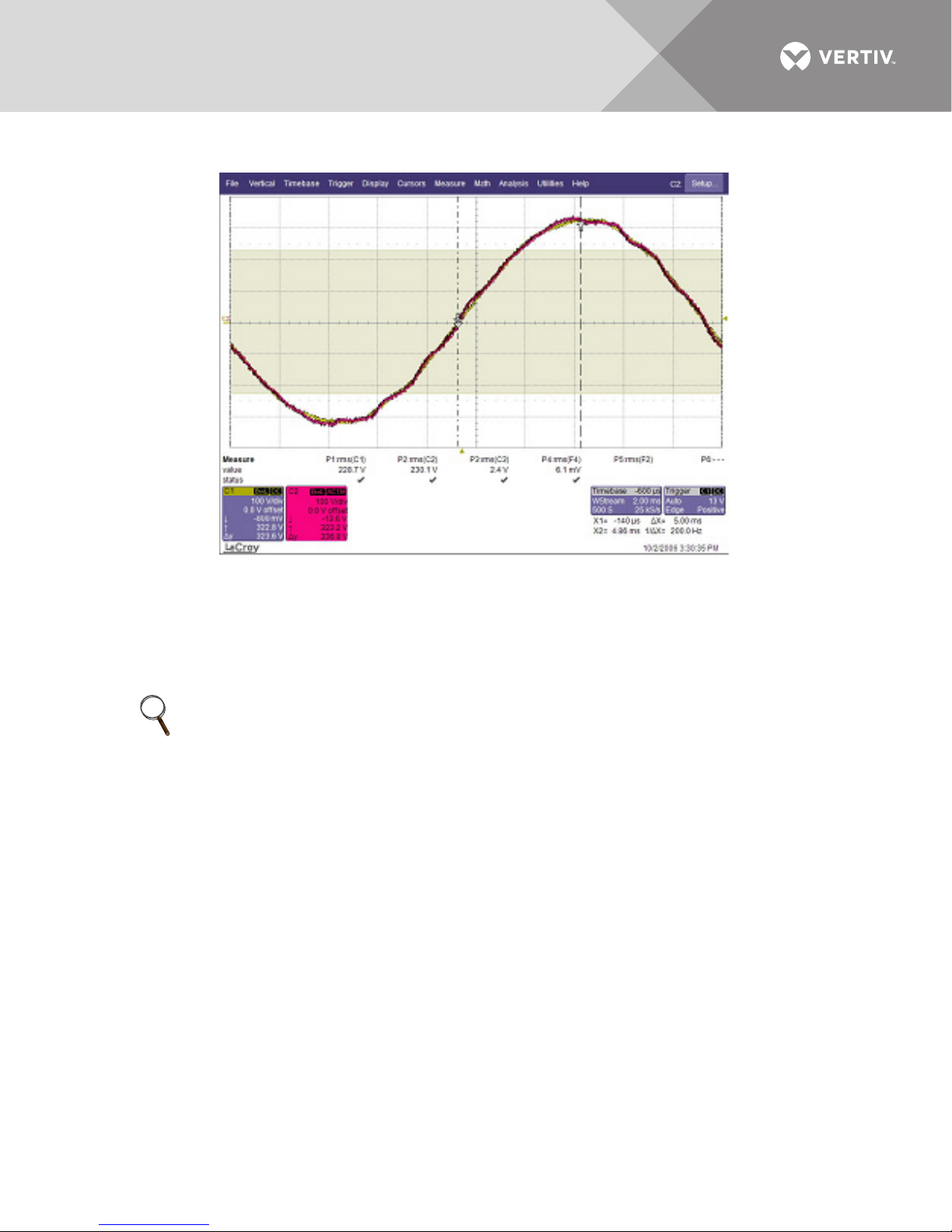
Figure 10 Synchro Error 0 [°]
When there is NO SYNC we need to determine the offset between the two waveforms, in the
example Figure 9 there is a difference of 88.56°. To ensure a correct synchronization, enter a
value in PNU 731.32 (the offset).
To calculate the offset value:
PNU 731.32 = phase-error [°] * 65536 / 360 PNU 731.32 = 88,56° x 65536 / 360 PNU 731.32 = 16121
NOTE1
If by using this formula you are not able to compensate the offset, try with the following formula:
PNU 731.32 = (360 - phase error [°]) * 65536 / 360
After calculating the new value for PNU 731.32, proceed with following steps to change it.
1. Close QS2 on the first UPS.
2. Wait for the Warning W1.1 - Bypass Switch Open - to be cleared.
3. Stop the inverter.
4. In PPVis click on
5. Set “Access level” to “Superservice”: PNU 51=4.
6. Set “Function Selection” to “HW-Init”: PNU 52=2.
7. Set PNU 731.32 “EXT_SYNCH_OFFSET” to “the new calculated value” (16121 in our example).
8. Set “Function selection” back to “Return”: PNU 52=0.
9. Set “Access level” back to “Normal operation”: PNU 51=1.
10. Start the inverter and open QS2 again, check that the SYNC is now according to example in Figure 10.
11. Close QS2 again.
Service Tools and select Parameter.
Vertiv™ |Liebert® Load Bus Sync™ Controller Installation Manual | 13
Page 18
3.3.3 Procedure complete for UPS1
NOTE
This offset compensation procedure must be followed for ALL the units connected to Liebert®
Load Bus Sync
Vertiv™ |Liebert® Load Bus Sync™ Controller Installation Manual | 14
™
Controller.
Page 19
3.4 Installation Example
Third-Party
UPS
(not by
Vertiv
™
)
Liebert®Load
Bus Sync
™
Controller
Liebert
®NX™
UPS Parallel
System
Short connection
between UPS’s and
Liebert
®
Load Bus
Sync
™
Controller
Long connection between
Master source and
Liebert
®
Load Bus Sync
™
Controller
Fuse
Floor 1
Supply
Floor 2
Supply
Floor X
Supply
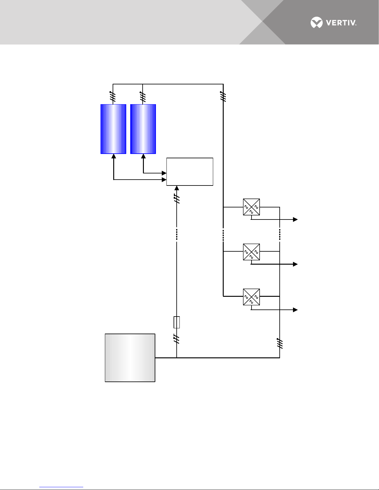
Figure 11 Installation example
Note the position of the Liebert® Load Bus Sync™ Controller. This unit’s location should be
selected so that the connections to the slave units are as short as possible. Install a 2A slow-blow
fuse on the phase signal line, as close as possible to the master unit.
Vertiv™ |Liebert® Load Bus Sync™ Controller Installation Manual | 15
Page 20

NOTES
Vertiv™ |Liebert® Load Bus Sync™ Controller Installation Manual | 16
Page 21

Vertiv™ |Liebert® Load Bus Sync™ Controller Installation Manual | 17
Page 22

Vertiv™ |Liebert® Load Bus Sync™ Controller Installation Manual | 18
Page 23

Page 24

VertivCo.com | Vertiv Headquarters, 1050 Dearborn Drive, Columbus, OH, 43085, USA
© 2018 Vertiv Co. All rights reserved. Vertiv and the Vertiv logo are trademarks or registered trademarks of Vertiv Co. All other names and logos referred to
are trade names, trademarks or registered trademarks of their respective owners. While every precaution has been taken to ensure accuracy and
completeness herein, Vertiv Co. assumes no responsibility, and disclaims all liability, for damages resulting from use of this information or for any errors or
omissions. Specifications are subject to change without notice.
SL-25358_REV2_8-18
 Loading...