

Page 1

Liebert® iCOM™
Installer/User Guide
Intelligent Communication and Monitoring for Liebert XDU
Page 2

The information contained in this document is subject to change without notice
and may not be suitable for all applications. While every precaution has been
taken to ensure the accuracy and completeness of this document, Vertiv
assumes no responsibility and disclaims all liability for damages resulting from
use of this information or for any errors or omissions. Refer to other local
practices or building codes as applicable for the correct methods, tools, and
materials to be used in performing procedures not specifically described in this
document.
The products covered by this instruction manual are manufactured and/or sold
by Vertiv. This document is the property of Vertiv and contains confidential
and proprietary information owned by Vertiv. Any copying, use or disclosure of
it without the written permission of Vertiv is strictly prohibited.
Names of companies and products are trademarks or registered trademarks of
the respective companies. Any questions regarding usage of trademark names
should be directed to the original manufacturer.
Technical Support Site
If you encounter any installation or operational issues with your product, check the pertinent section of this
manual to see if the issue can be resolved by following outlined procedures.
Visit https://www.Vertiv.com/en-us/support/ for additional assistance.
Vertiv | Liebert® iCOM™Instal ler/User Guid e
Page 3

TABLE OF CONTENTS
1 Getting Started with Liebert® iCOM™ 1
1.1 Touchscreen Display and User Interface 1
1.2 Touchscreen Status Dial 3
1.2.1 Dial Background Color Status Indication 4
1.3 Control Header 4
1.3.1 Powering On the Liebert® iCOM™ and Logging In/Unlocking Controls 5
1.3.2 Powering On the Thermal Management Unit 5
1.3.3 Powering Off the Thermal Management Unit 7
1.3.4 Logging Out 7
1.3.5 Setting the Date and Time 7
1.3.6 Searching 8
1.4 Using Context Sensitive Help 8
1.5 About Liebert®iCOM™ Version 8
1.6 Accessing the User, Service, and Advanced Menus 9
1.7 User Menu 9
1.7.1 User Menu Options 9
1.8 Service Menu 10
1.8.1 Service Menu Options 10
1.9 Advanced Menu 11
1.9.1 Advanced Menu Options 11
2 User Operation 13
2.1 Viewing and Editing Setpoints for the Cooling Unit 13
2.1.1 Editing Temperature Setpoints 13
2.2 Viewing Unit Alarms 14
2.2.1 To View Alarms 14
2.2.2 Silencing an Audible Alarm 15
2.2.3 Acknowledging Alarms 15
2.3 Viewing the Event Log 16
2.4 Viewing Sensor Data 16
2.5 Managing Run Hours for a Component 16
2.5.1 Setting Run Hours to Zero 16
3 Service Operation 17
3.1 Editing Setpoints for the Cooling Unit 17
3.1.1 Setpoints Options 17
3.2 Pump Control 17
3.2.1 Configuring Pump Setpoints 17
3.3 XDU Fan Control 18
3.3.1 Configuring Fan Setpoints 19
i
Page 4

3.4 XDU Pump Lead/Lag Control 20
3.5 XDU Pump Monitoring 20
3.6 XDU Loss of Flow Control 20
3.7 Setting General Thermal Management Unit Options 20
3.7.1 Setting Miscellaneous Options 21
3.8 XDU Quick Start 22
3.8.1 Configuring Quick Start 22
3.8.2 Setting Fan Options 23
4 Managing Events: Alarms,Warnings,andMessages 27
4.1 Event Properties 27
4.1.1 Alarms and Events Panel Fields 27
4.2 Enabling Events and EditingEventSettings 28
4.3 Selecting Event Type and SettingAlarm/WarningNotification 28
4.3.1 Notification Properties 29
4.4 Enabling the Audible Alarm Notification 31
4.5 Remote Alarm Device and Customer Input Events 31
4.5.1 Setting Up Customer Input Events 31
5 External Monitoring andBuilding ManagementSystems 33
5.1 BMS and IntelliSlot Settings 33
5.1.1 Configuring BMS Communication with Embedded Unity 33
5.1.2 Setting BMS Control Settings 34
5.1.3 Setting BMS Backup Setpoints 35
5.2 Communication Setup with Embedded Unity 35
5.2.1 Connecting to the BMS 36
5.2.2 Embedded Unity User and Password 38
5.2.3 Unity Restart and Restore Defaults 39
5.2.4 System Configuration 39
5.2.5 Local Users Configuration 41
5.2.6 Network Configuration 42
5.2.7 Web Server Configuration 45
5.2.8 Remote Services Configuration 47
5.2.9 Velocity Protocol Configuration 50
5.2.10 Messaging Configuration 51
5.2.11 BACnet Protocol Setup 56
5.2.12 Modbus Protocol Setup 59
5.2.13 SNMP Protocol Setup 61
5.3 Unity Status Readings 66
5.4 Unity Support Information 66
5.4.1 Support Folder Settings 66
5.4.2 Configuring Active Networking Settings 68
ii
Vertiv | Liebert® iCOM™Inst aller/User G uide
Page 5

6 Configuring Auxiliary Devices 71
6.1 Power Monitoring 71
6.1.1 To Setup Power Monitoring 71
7 Administering Firmware, Settings and Security 73
7.1 Liebert® iCOM™ Firmware Upgrades 73
7.2 iCOM Firmware Upgrades 73
7.2.1 Compatibility with Earlier Versions of Liebert®iCOM™ 73
7.2.2 Updating Liebert® iCOM™ Control Board Firmware 73
7.2.3 Reverting to Firmware in Dormant Partition 75
7.3 Backing Up and Restoring Control Board Settings 75
7.3.1 Control Board Back Up and Restore Options 76
7.4 Managing Access Permission and Passwords 76
8 Performing Diagnostics 77
8.1 Cooling Unit Status LED 77
8.2 Enabling Manual Mode for Diagnostics 77
8.2.1 Disabling Diagnostics Manual Mode 78
8.3 Diagnosing Evaporator Fan Issues 78
8.3.1 Diagnostics—Evaporator Fan Options 78
8.4 Diagnosing Digital Output Issues 79
8.4.1 Diagnostics—Digital Output Options 79
8.5 Diagnosing Analog Output Issues 79
8.5.1 Diagnostics—Analog Output Options 79
8.6 Diagnosing Customer Input Issues 80
8.6.1 Diagnostics—Customer Input Options 80
8.7 Diagnosing Water Leak Detection Issues 80
8.7.1 Diagnostics—Water Leak Detection Options 80
9 Customizing the Liebert® iCOM™ Display 81
9.1 Setting General Display Properties 81
9.1.1 Unit Display Options 81
9.2 Customizing Main Display Views 82
9.2.1 Moving Content 82
9.2.2 Resizing Content 82
9.2.3 Adding and Adjusting Content 83
9.2.4 Removing Content 84
9.3 Customizing Parameter and Field Labels 84
9.3.1 Exporting, Importing, and Customizing Labels Using a Text Editor 86
10 Hardware 89
10.1 Fluid Temperature Sensor 89
10.2 Inlet and Outlet Air Sensors 89
10.3 Liebert® Liqui-tect Leak Detection 89
iii
Page 6

10.3.1 Point Leak-Detention Sensor 89
10.3.2 Zone Leak-Detection Sensor 89
Appendices 91
Appendix A: Technical Support and Contacts 91
Appendix B: Setpoints and Alarm Settings by Line ID 93
iv
Vertiv | Liebert® iCOM™Inst aller/User G uide
Page 7

1 GETTING STARTED WITH LIEBERT® iCOM™
The Liebert® iCOM™ offers the highest capability for unit control, communication, and monitoring of Liebert® thermal
management units. It is available factory installed on new units and assemblies or may be retrofitted in existing units.
1.1 Touchscreen Display and User Interface
The Liebert iCOM touchscreen and user interface speeds set up and installation and simplifies control of Liebert® thermal
management units, literally putting cooling system monitoring and management at your fingertips.
• The resistive touchscreen is used with a firm touch, or consider using a stylus when interacting with the
touchscreen.
• User and service menus are password protected to prevent unauthorized changes to cooling unit operation.
• The touchscreen is back lit and auto-dims after a period on non-use, then turns off. Touch the screen to
illuminate the main screen.
• iCOM ships with default settings for efficient and effective operation of most cooling units and is easily
configured to meet any need.
• iCOM menus and displays are based on the options installed on the cooling units that it monitors and manages.
1
Page 8
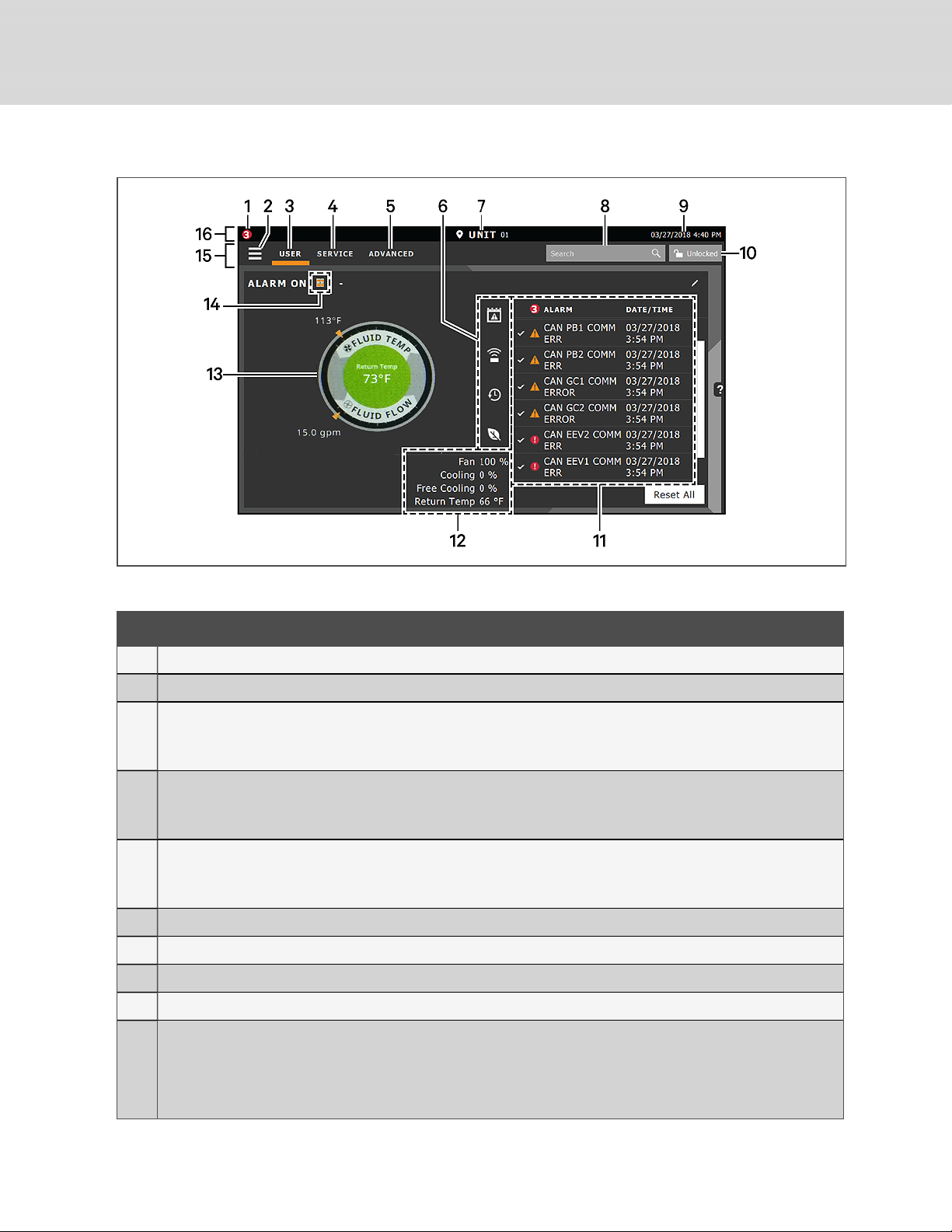
Figure 1.1 Liebert® iCOM™ Main Display
Table 1.1 Main Display Controls and Options
Item Description
1 Alarms present. Displays the number of active alarms.
2 Menu icon. When unlocked, displays a menu for user or service options depending on which icon is selected.
User icon. When selected, the user optionsare available on the m ain display and menu.
3
NOTE: You must unlock the display with the User PIN to acces s the menu and options.
See Powering On the Liebert® iCOM™and Logging In/Unlocking Controls on page5.
Service icon. When selected, the service options a re a vailable on the m ain display and menu.
4
NOTE: You must unlock the display with the Service PIN to access the menu and options.
See Powering On the Liebert® iCOM™and Logging In/Unlocking Controls on page5.
Advanced icon. When selected, the advanced optionsare available on the main display and menu.
5
NOTE: You must unlock the display with the Service PIN to access the menu and read-onlyoptions.
See Powering On the Liebert® iCOM™and Logging In/Unlocking Controls on page5.
6 Cooling unit parameters. Status display of selected system param eter settings. See Adding and Adjusting Content on page83
7 Unit Identification. You may customize the unit name up to six characters/numbers.
8 Search icon. O pen the keyboard to search for controls a nd setting loca tions. See Searching on page8.
9 Date/Time.
Lock/Unlock icon. Indicates whether or not the user and service optionsare accessible.
10
• Locked icon: display is read-only.
• Unlocked icon: user or service is logged in and options are accessible.
See PoweringOn the Liebert® iCOM™ and Logging In/Unlocking Controlson page5.
2
Vertiv | Liebert® iCOM™Inst aller/User G uide
Page 9
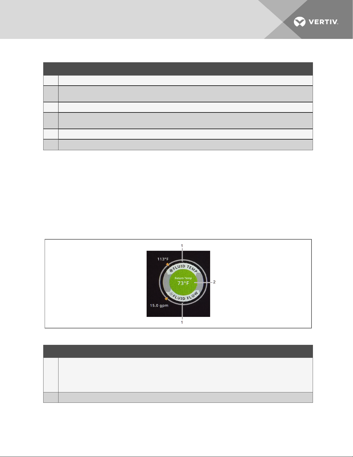
Table 1.1 Main Display Controls and Options (continued)
Item Description
11 Secondary content panel. When accessingsettings/configuration via the menus, the settings display in the right, secondary panel.
Summary of current unit function. You can customize to showfan speed, cooling, percentages from any installed device, and any physical
12
(sensor) values.
13 Status Dial. Circular display of setpointsand environmental conditions of the unit. See Touchscreen Status Dial below.
Teamwork mode icon. In a panel with Status content, the Teamwork Mode icon indicates the mode selec ted. For details and descriptions of the
14
teamwork controls, see Team work Modes.
15 Control header. Controls to access the user and service m enus. See Control Header on the next page.
16 Status Header. Displays the alarm status, unit identification, and the current date and time.
1.2 Touchscreen Status Dial
The dial in the primary control panel displays read-only control sensors, setpoints, and environmental conditions for unit
status at a glance. See Figure 1.2 below.
The center of the dial displays sensor readings and changes color according to alarm thresholds as the readings rise and
fall. See Dial Background Color Status Indication on the next page.
Touching the center of the dial cycles through a set of sensor settings, and you can select the readings displayed. See
Adding and Adjusting Content on page83.
Figure 1.2 Dial Sections
Table 1.2 Dial Sections
Item Description
Control sensor and its setpoint. The sensors and setpoints displayed depend on the configuration of y our unit.
You may see only temperature control, or if the unit includes humidity control, that displays on the dial as well.
1
If the sensor selected for fan control is the same as that selected for temperature control, the dial displays the fa n control sensor and setpoint, as
shownin Figure 1.2 above.
2 Single or multiple sensor readings. Cycle through readings by touching the displayed reading.
1 G ettin g Started with Liebert® iCOM™
3
Page 10
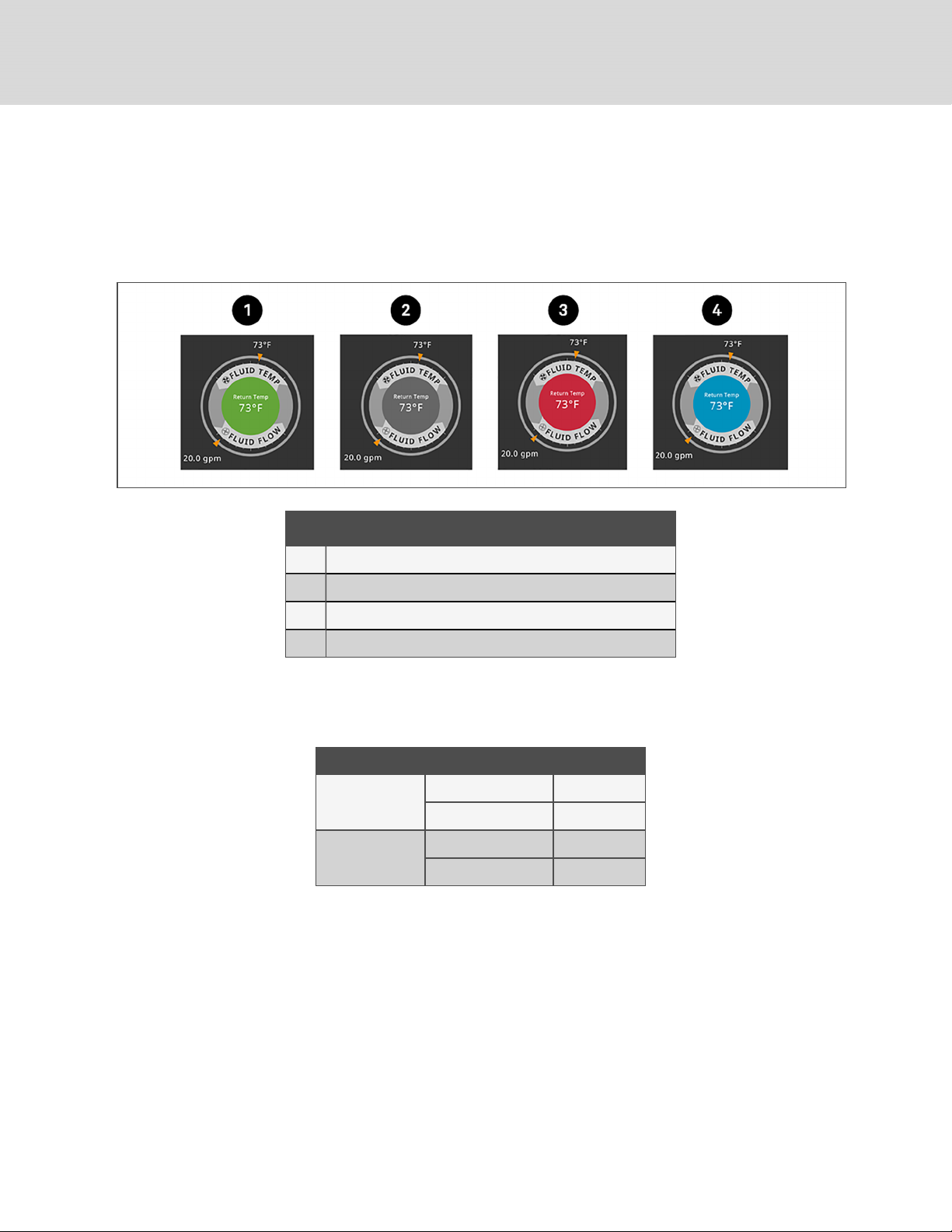
1.2.1 Dial Background Color Status Indication
The background color of the dial indicates whether or not the unit is powered on, and it also responds to threshold settings
of the control sensor reading. See Figure 1.3 below. Table 1.3 below describes the background color displayed if the
selected sensor reading has threshold limits set.
Figure 1.3 Dial Background Colors
Item Description
1 Sensor reading is within threshold limits..
2 Unit is powered off.
3 Sensorreading is above thresholdlimit or the unit is in an alarm condition.
4 Sensor reading is below threshold limit.
Table 1.3 Background Color Displayed by Selected
Value and Threshold Limit
Sensor/Value Selected Threshold Limit Backgroun d Colo r
Return Temp
Supply Temp
None Blue
High return temperature Red
Low supply temperature B lue
High supply temperature Red
1.3 Control Header
The control header contains the controls to access the user and service settings. The display is locked when started initially
and when restarted after a period of inactivity.
4
Vertiv | Liebert® iCOM™Inst aller/User G uide
Page 11

1.3.1 Powering On the Liebert® iCOM™ and Logging In/Unlocking Controls
Liebert® iCOM™ is powered on when power is switched on at the cooling unit’s disconnect switch and you activate the
display by touching it.
iCOM is locked when started and also locks after a period of inactivity to prevent unauthorized changes. A four- digit
password is required to access the user and service menus and options, and the advance menu displays as read-only when
logged in at the service level.
NOTE: The factory default inactivity period is one minute. To change the inactivity period, see Customizing Main
Display Views on page82.
NOTE: The factory default password for user and service log in are provided. We recommend you change passwords
as necessary to prevent unauthorized changes. See Managing Access Permission and Passwords on page76.
• Default user password: 1490
• Default service password: 5010
To unlock the controls:
1. On the header, touch .
The keypad opens.
2. Touch the numbers/characters for your password, then touch .
Depending on the password entered and your level of access, the User and/or Service options and view only
access to the Advanced menu are accessible. See Accessing the User, Service, and Advanced Menus on
page9.
1.3.2 Powering On the Thermal Management Unit
NOTE: Depending on the operating state, there are start and stop priority switches that may prevent the cooling unit
from operating even though power to the unit is switched on and you have turned it on via Liebert® iCOM™.
The cooling unit operates only when all switches are closed. For example, even though you have turned on the unit
through iCOM, if the BMS remote monitoring system is sending a command to turn off the unit, the cooling unit
remains off.
NOTE: You must be logged in to access the menu options. See Powering On the Liebert® iCOM™ and Logging
In/Unlocking Controls above.
To power on the unit:
1. Touch , then >Turn Unit On. The TURN UNIT ON dialog opens.
2. Touch Turn Unit On. The cooling unit starts and the operating status is displayed as shown in Figure 1.4 on the
next page.
1 G ettin g Started with Liebert® iCOM™
5
Page 12
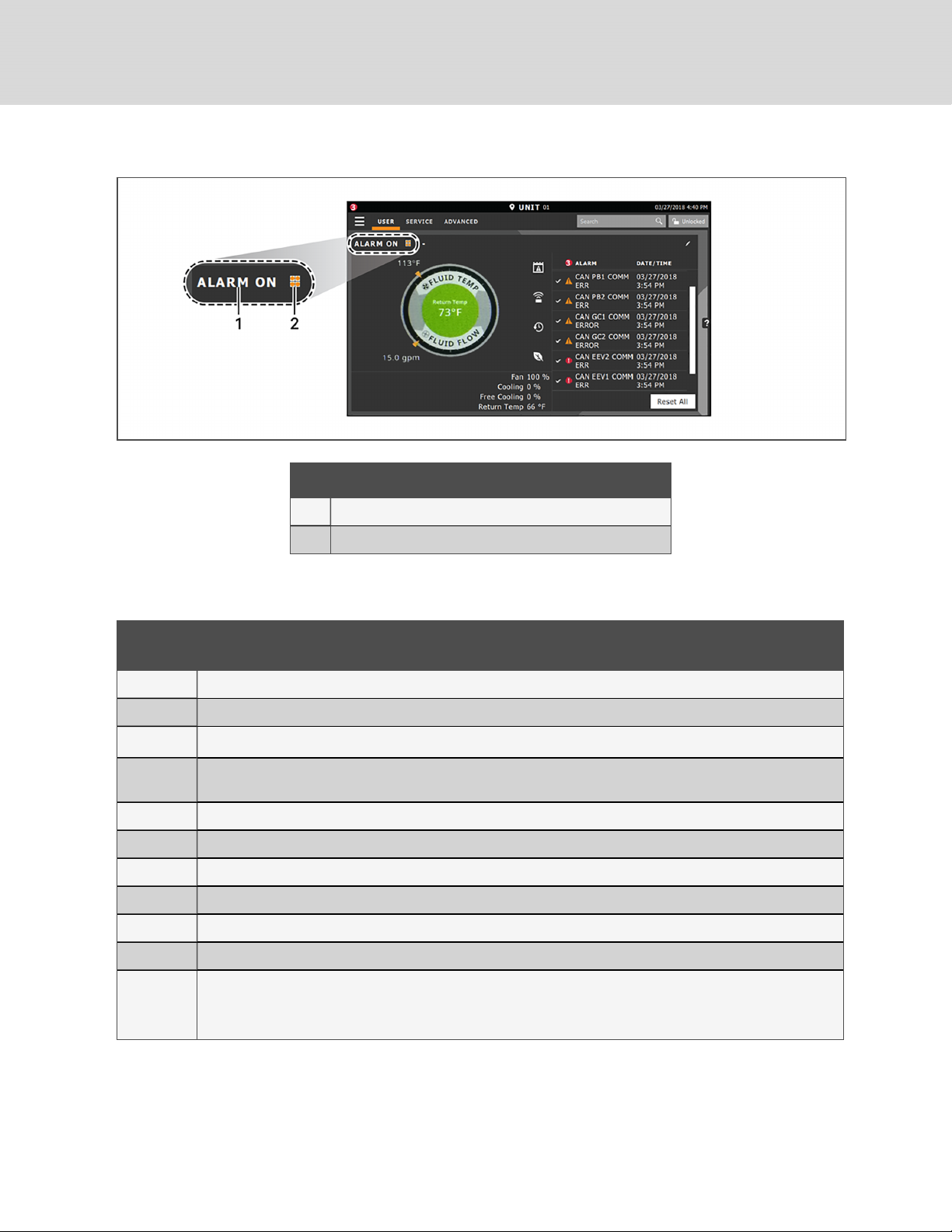
Figure 1.4 Unit Status On Liebert® iCOM™ Display
Item Description
1 Current status of the unit. See Table 1.4 below.
2 Teamwork icon. See ViewingTeamwork, Standby, andCascade Status.
Table 1.4 Cooling Unit Statuses Displayed
Unit Status
Text
ALARM OFF An alarm forced the unit to turn off. See Viewing Unit Alarms on page14.
MANUAL Controlled by a service technician. See Enabling Manual Mode for Diagnostics on page77.
DISPLAY OFF
ALARM
STANDBY
STANDBY In standby because of service menu setting. See Assigning Cooling Units to Standby (Lead/Lag).
TIMER OFF Scheduled on a timer and is in sleep mode waitingfor the next start interval. See Scheduling Condenser and Cooling Unit Tasks.
UNIT ON O perating normally without alarms or warnings.
WARNING ON Active warning, but still operating. See ViewingUnitAlarms on page14.
ALARM ON Active a larm, but still operating. See Viewing Unit Alarms on page14.
TIMER Scheduled on a timer to operate, and is in operating mode. See Scheduling Condenser and Cooling Unit Tasks.
REMOTE OFF
Description
Unit is turned O ff at the iCOM display. See Powering On the Thermal Management Unit on the previous page.
In standby because of a n active alarm on the unit. See Viewing Unit Alarms on page14.
Turned off by remote shutdown terminal.
Occurs when a normally closed set of 24V contacts opens. The Rem ote On/Off and Display On/Off switches are in series, and the cooling
unit will only turn on if both switches are on/closed. If one is off/open, the unit turns off.
6
Vertiv | Liebert® iCOM™Inst aller/User G uide
Page 13
Table 1.4 Cooling Unit Statuses Displayed (continued)
Unit Status
Text
MONITORING
OFF
BACK-DRAFT Unit is non-operational, but EC fan is operating as a back-draft damper.
RESTART
DELAY
Description
Turned off by remote monitoring system.
Check the remote m onitoringdevice or call Vertiv technical support for assistance.
Not yet operational after a power c ycle because the restart delay timer is active.
1.3.3 Powering Off the Thermal Management Unit
NOTE: You must be logged in to access the menu options. See Powering On the Liebert® iCOM™ and Logging
In/Unlocking Controls on page5.
1. Touch , then >Turn Unit Off. The TURN UNIT OFF panel opens.
2. Touch Turn Unit Off. The unit begins a power off countdown and then powers off.
1.3.4 Logging Out
Log out occurs automatically when the display back light turns off for inactivity.
NOTE: The factory default inactivity period is one minute. To change the inactivity period, see Setting General Display
Properties on page81
• To log out manually, touch the lock icon. The icon indicates locked.
1.3.5 Setting the Date and Time
The correct date and time is critical for warnings, alarms, and scheduling.
1. Touch , then > Display Options > Display Properties > Date &Time.
2. Touch the date field, use the arrows to select the date, and touch OK.
– or –
Touch the time field, use the arrows to set the time, and touch OK.
3. Select the date and time format if necessary.
4. Touch Save.
1 G ettin g Started with Liebert® iCOM™
7
Page 14
1.3.6 Searching
When logged in, you can use the display search to find the location of settings options based on a term, service code, or
parameter. You can also search by the line ID used in the iCOM™ before the touchscreen model. For a listing of the line IDs,
see Setpoints and Alarm Settings by Line ID on page93.
NOTE: You must be logged in to access the display search. See Powering On the Liebert® iCOM™ and Logging
In/Unlocking Controls on page5.
1. In the control header, touch the search field. The keyboard opens.
2. Type the term and touch . A list of locations that contain the searched term opens.
3. To go to a listed location, touch an item, then touch Go. The panel for the selected location opens.
– or –
To view the service codes and parameter entries related to the searched term, touch View Parameter Directory
Entries (the number of related entries is included in the option). The Parameter Directory opens. You may
further refine the search in the directory.
1.4 Using Context Sensitive Help
Touching the Help icon, , on the right-hand side of the display opens the Help drawer with information about the
panel or dialog currently on the display.
You can use search and the topic index to find further information.
To close the Help drawer, touch the close arrow, .
1.5 About Liebert®iCOM™ Version
The version, build, and other firmware information for the Liebert® iCOM™ display board may be helpful when servicing or
troubleshooting. To locate the firmware version of the iCOM control board, see Updating Liebert® iCOM™ Control Board
Firmware on page73.
• Touch , then > About. The ABOUT panel opens.
8
Vertiv | Liebert® iCOM™Inst aller/User G uide
Page 15

1.6 Accessing the User, Service, and Advanced Menus
iCOM™ operating functions that monitor and control a cooling unit are accessed via the User and Service menus.
NOTE: You must be logged in to access the menu options. See Powering On the Liebert® iCOM™ and Logging
In/Unlocking Controls on page5.
1. To access a menu, touch the icon for the menu you want, , or , in the control header. See
Control Header on page4. The orange bar appears below the menu name when selected indicating that this is
the menu content that will be displayed.
2. Touch the menu icon, . The menu opens.
1.7 User Menu
The user menu lets you view system and unit statuses and edit some setpoints.
1.7.1 User Menu Options
Setpoints
Opens the SETPOINTS panel. See Viewing and Editing Setpoints for the Cooling Unit on page13.
Active Alarms
Opens the ALARMS panel. See Viewing Unit Alarms on page14.
Event Log
Opens the EVENT LOG panel. See Viewing the Event Log on page16.
Sensor Data
Opens the SENSOR DATA panel. See Viewing Sensor Data on page16.
Display Options
Opens the Display Options menu:
• Customize Layout: See Customizing Main Display Views on page82.
• Custom Labels: See Customizing Parameter and Field Labels on page84.
• Date & Time: See Setting the Date and Time on page7.
Total Run Hours
Opens the RUN HOURS panel. See Managing Run Hours for a Component.
1 G ettin g Started with Liebert® iCOM™
9
Page 16

About
Opens the ABOUT panel. See About Liebert®iCOM™ Version on page8.
Turn Unit On/Off
Depending on unit’s status, open the TURN UNIT ON or TURN UNIT OFF dialog. See Powering Off the Thermal
Management Unit on page7, or Powering Off the Thermal Management Unit on page7.
1.8 Service Menu
The service menu lets you view and edit setpoints and perform many other functions.
1.8.1 Service Menu Options
Setpoints
Opens the SETPOINTS panel. See Editing Setpoints for the Cooling Unit.
Diagnostic/Service
Opens the Diagnostic/Service menu:
• Diagnostics: See Performing Diagnostics.
• Technical Support: Contact information for the cooling unit andiCOM™ display.
Alarm/Event Setup
Opens the ALARMS & EVENTS panel. See Managing Events: Alarms,Warnings,andMessages.
BMS & Teamwork
Opens the BMS & Teamwork menu:
• U2U Setup: See Configuring U2U Network Settings.
• BMS Setup: See BMS and IntelliSlot Settings on page33
Scheduler
Opens the SCHEDULER panel. See Scheduling Condenser and Cooling Unit Tasks.
Options Setup
Opens the OPTIONS SETUP panel. See Setting General Thermal Management Unit Options on page20.
Auxiliary Device Setup
Opens the Auxiliary Device Setup menu:
• Sensors: See Wired Remote Sensors.
10
Vertiv | Liebert® iCOM™Inst aller/User G uide
Page 17

Backup & Security
Opens the Backup & Security menu:
• Display Backup and Restore: See Backing Up and Restoring Control Board Settings on page75.
• Control Backup and Restore: See Backing Up and Restoring Control Board Settings on page75
• Display Upgrade: See Updating Liebert® iCOM™ Control Board Firmware on page73.
• Control Upgrade: See Updating Liebert® iCOM™ Control Board Firmware on page73.
• Manage Permissions: See Managing Access Permission and Passwords.
Turn Unit On/Off
Depending on unit’s status, open the TURN UNIT ON or TURN UNIT OFF dialog. See Powering On the Thermal
Management Unit on page5, or Powering Off the Thermal Management Unit on page7.
1.9 Advanced Menu
The advanced menu provides a read-only view of the advanced set up and factory level settings.
1.9.1 Advanced Menu Options
Factory Settings
Unit code and configuration settings.
Diagnostics
Details about control and cooling operation.
Expert Settings
Parameters and settings for use by trained professionals only.
Runtime Monitoring
Details about component run times.
Control Override
Allows simulating events and override of analog outputs beyond normal limits.
Parameter Directory
A searchable list of all parameters in the user interface. See Setpoints and Alarm Settings by Line ID on page93.
1 G ettin g Started with Liebert® iCOM™
11
Page 18

This page intentionally left blank.
12
Vertiv | Liebert® iCOM™Inst aller/User G uide
Page 19

2 USER OPERATION
2.1 Viewing and Editing Setpoints for the Cooling Unit
NOTE: User level access allows viewing and editing only a limited number of setpoints. To view or adjust all setpoints,
you must have service level access. See Editing Setpoints for the Cooling Unit on page17.
NOTE: Depending on the type of thermal management unit, included components, and control settings of your
system, all of the options listed may not be available on your iCOM™ display.
2.1.1 Editing Temperature Setpoints
1. Touch , then > Setpoints > Temperature Control.
The TEMPERATURE CONTROL secondary panel opens.
2. Refer to User Temperature Setpoint Options below, Temperature Control—TemperatureSetpointsandCooling
Operation, then touch Save.
The setpoint is updated.
• Touch Cancel to discard the changes.
NOTE: Depending on the type of thermal management unit, included components, and control settings of your
system, all of the options listed may not be available on your iCOM™ display.
User Temperature Setpoint Options
2nd Temperature Setpoint
Alternate setpoint activated by customer input (remote alarm device). When customer input connection is 2nd
Setpoint, this value becomes the active temperature setpoint.
BMS Backup Temp Setpoint
Selects a temperature setpoint that activates in the event of a BMS timeout. The BMS timer must be configured for
this setpoint to activate. See Setting BMS Backup Setpoints on page35.
Temperature Setpoint Act
Read-only display of adjusted temperature setpoint when one of the following is active:
• Temperature compensation
• BMS backup temperature setpoint
• Customer input setpoint (remote alarm device)
Temperature Setpoint
Supply fluid temperature that the unit maintains via fan speed change.
2 U ser Operation
13
Page 20
2.2 Viewing Unit Alarms
The ALARMS panel lists active alarm and warning events. Table 2.1 below describes the type and state of the alarm
shown by indicator dots.
Table 2.1 Alarm Status and Type Indicators
Indicator Description
Yellow dot Warning event.
Red dot Alarm event.
Circle Event condition has clea red, but still must be acknowledged. See Acknowledging Alarms on the facing page.
2.2.1 To View Alarms
1. Touch , then > Alarms. The ALARMS panel opens.
2. Touch an alarm to display the ALARM DETAILS panel.
Alarm Fields
Alarm
Name of the event.
Date
Date event was logged.
Time
Time event was logged
Alarm Detail Fields
Alarm
Name of the event.
Alarm Type
Number representing the event type.
• 1 : Warning
• 2: Alarm
Date/Time
Date and time the event was logged.
14
Vertiv | Liebert® iCOM™Inst aller/User G uide
Page 21

Duration
Time elapsed since event was logged.
Threshold
Sensor reading at which an event is triggered.
Unit
Cooling unit to which the alarm applies.
Value
The current value to which the threshold is compared.
2.2.2 Silencing an Audible Alarm
Touch the screen to silence an audible alarm. If the alarm is non-latching, the alarm silences when the condition clears.
NOTE: The audible alarm must be enabled in display options to sound. See Enabling the Audible Alarm Notification on
page31.
2.2.3 Acknowledging Alarms
Depending on the notification settings, alarms and warnings must be acknowledged or reset. An event is active as long as it
is unacknowledged, with the exception of the network failure events described in Table 2.2 on the next page. Once
acknowledged, an event remains active until the situation that triggered the event is resolved, see Table 2.1 on the
previous page, for event status indicators. When an event is acknowledged and cleared, it is removed from the Alarms panel
and the LED stops flashing red.
NOTE: Acknowledging alarm events does not clear them. To clear an issue, it must be corrected, reset automatically
by the controller, or reset manually.
To Acknowledge Alarms
1. On the ALARMS panel, touch Acknowledge All. A check mark overlays the status indicator of the active alarms
and warnings, and these automatically clear when the condition is no longer present.
• If a critical event must be manually reset, the acknowledged items are listed with a Reset All button on
the ALARMS panel.
2. Touch Reset All to manually reset the condition.
2 U ser Operation
15
Page 22
2.3 Viewing the Event Log
The event log is a list by date/time of the last 400 events generated by iCOM™ for the thermal management unit.
• On the User menu, touch Event Log. The EVENT LOG for the cooling unit opens. Table 2.2 below describes
the color coded status for each event.
NOTE: Depending on the type of thermal management unit, included components, and control settings of your
system, all of the options listed may not be available on your iCOM™ display.
Table 2.2 Event Status/Type Indicators
Indicator Description
Green dot Message.
Yellow dot Unacknowledged warning event. See Acknowledging Alarms on the previous page.
Red dot Unacknowledged alarm event. See Acknowledging Alarms on the previous page.
White dot withcheck-mark ov erlay Acknowledged event, the cause stillexists.
White circle Acknowledged event, the cause is cleared.
2.4 Viewing Sensor Data
The Sensor Data panel lists the standard and optional sensors monitored by iCOM™and the current reading of each sensor.
• Touch , then > Sensor Data. The SENSOR DATA panel opens.
A secondary panel displays the DAILY SENSOR READING SUMMARY, which shows temperature, humidity, and
dew point readings for the cooling unit.
NOTE: Depending on the type of thermal management unit, included components, and control settings of your
system, the options on your iCOM display may differ.
2.5 Managing Run Hours for a Component
You can view the run hours for components on a cooling unit, set the total run time limit, and reset total run hours to zero.
1. Touch , then > Total Run Hours. The RUN HOURS panel opens and the current hours for each
component are listed in the Total Run Hours column.
To reset the total run hours to zero, see Setting Run Hours to Zero below.
2. Use the slider to set the total run time limit for each component, then touch Save. The limits are set.
2.5.1 Setting Run Hours to Zero
1. On the RUN HOURS panel, touch to check each box in the Total Run Hours column next to the component(s) to
reset. The Set to Zero button becomes available.
2. Touch Set to Zero. The total run hours for the selected component(s) is set to zero.
16
Vertiv | Liebert® iCOM™Inst aller/User G uide
Page 23

3 SERVICE OPERATION
3.1 Editing Setpoints for the Cooling Unit
Setpoints are the means by which cooling unit operation is controlled.
NOTE: Depending on the type of thermal management unit, included components, and control settings of your
system, all of the options listed may not be available on your iCOM™ display.
3.1.1 Setpoints Options
Fan Control
See Configuring Fan Setpoints on page19.
Pump Control
See Configuring Pump Setpoints below.
3.2 Pump Control
The Liebert® XDU shall utilize variable speed pumps to supply the maximum amount of fluid flow required by the server
configuration. The desired pump flow rate setpoint shall be determined by the end-user. XDU shall come with two variable
speed pumps, each pump operating via its own VFD. Pumps are 100% redundant of one another.
A flow meter shall monitor the actual XDU system flow rate. The flow rate value sensed by the flow meter shall be used to
control the actual pump speed to match the desired system flow rate setpoint. The flow meter is mounted on the discharge
(leaving) fluid line.
3.2.1 Configuring Pump Setpoints
Pump Control Options
Fluid Flow Rate @ Full Scale (%)
Flow rate corresponding to 20ma signal from the flow sensor (sensor output is 4-20ma) [Range 10-1000 lpm, default
115 lpm]
Fluid Flow Rate Setpoint (GPM)
Determines the speed output of the operating pump
Fluid Pump Initial Speed (%)
Pump speed at startup [Range 25-100%, default 25%]
Fluid Flow Proportional Band (GPM)
Value determines how aggressive the pump shall operate as flow rate deviates from fluid flow setpoint
Fluid Flow Dead Band (GPM)
3 S ervice Op eration
Defines the flow value where there will be no change in pump output as flow deviates from setpoint
17
Page 24

Fluid Flow Integration Time
Serves to push or pull the flow rate back in line with set point based on how long and how far away the measured
value is away from Set Point
Pump Transition Duration (sec)
Determines how long lead pump will operate while transitioning to lag pump
Pump Sequence
Determines which pump shall operate as the lead/lag. If set for Auto, pumps will operate based off run hours.
Pump Rotation Frequency (days)
Determines how often pumps will rotate from lead to lag [Range 0-30 Days, default 7 days]
Perform Pump Rotation
Forces the unit to perform a manual pump rotation
Loss of Flow Detection Delay (sec)
Delay time that must surpass in order to initiate ‘Loss of Flow’ alarm once loss of flow is detected
Fluid Check Speed Threshold
Defines how far the pump speed must change before ‘Check Fluid System’ notification is activated [Range 2-100%,
default 10%]
Expected Speed Reset
Resets the expected speed 60 second timer for the ‘Check Fluid System’ notification
Minimum Fluid Flow Volume
Determines the minimum flow the system can move
3.3 XDU Fan Control
The Liebert® XDU shall utilize two EC fans to provide the maximum rated airflow at 100% fan speed. Airflow shall help
determine the leaving fluid temperature from the discharge of the XDU. Both fans shall operate simultaneously at the same
speed to provide the airflow needed to maintain the control setpoint for the leaving fluid temperature. The fans are not
redundant of one another.
Each fan is self-monitoring and will provide a digital signal if the fan is powered but fails to operate. On the failure of one fan,
the remaining fan in operation shall continue to operate and increase speed to compensate for the failed fan.
18
Vertiv | Liebert® iCOM™Inst aller/User G uide
Page 25

3.3.1 Configuring Fan Setpoints
Configures fan speed control to operate independent of pumps loading (decoupled mode).
1. Touch , then > Setpoints > Fan Control. The FAN CONTROL secondary panel opens.
2. Adjust the setpoint options, then touch Save. The setpoint is updated.
• Touch Cancel to discard the changes.
Fan Control Options
Airflow Calibration
Maximum allowed fan output voltage.
Fluid T
Sensor monitoring the discharge fluid temperature will determine the fan speed output
Fan Control Sensor
Fluid T sensor monitoring the discharge fluid temperature will determine the fan speed output.
Fan Control Type
Selects the method of control for the fan motor.
• Proportional: Regulation based on the difference between the fan control sensor reading and the fan setpoint.
• PI: Regulation is based on proportional and integral terms. Provides best temperature control and helps avoid
fan speed oscillation.
• Adaptive PID: Auto-tuning PID control loop, can be set for cooling or fan speed.
Fan Speed Proportional Band
Adjusts the fan speed based on the deviation from the setpoint. A smaller number causes faster reaction to
temperature changes.
Fan Speed Integration
Adjusts fan speed based on time away from the setpoint to maintain accurate temperature control.
Maximum Fan Speed
Maximum percentage at which the fans will operate.
Minimum Fan Speed
Minimum percentage at which the fans will operate [15%, range 1.5 -10 v, default 1.5 v].
Proportional band adjusts fan speed activation point based on a deviation from setpoint by placing half of the
selected value on either side of the fan speed control setpoint. A smaller number causes a faster reaction in fan speed.
3 S ervice Op eration
19
Page 26
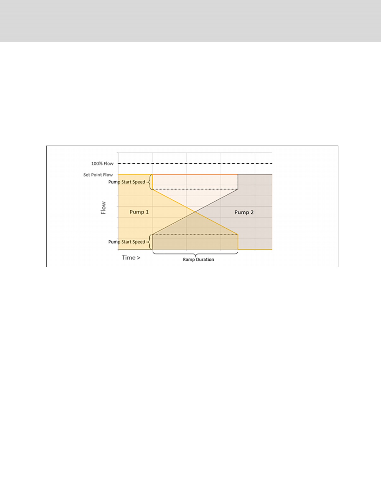
3.4 XDU Pump Lead/Lag Control
The two pumps in the Liebert XDU are lead/lag controlled to maintain equal runtime between the pumps, reduce corrosion,
and maintain the wetted seal surfaces of the lag pump. Only one pump shall operate at any given time to provide flow. The
lead/lag switchover of the two pumps is managed by the iCOM controller and shall switch operation of the pumps from lead
to lag without the interruption of flow. This is accomplished by first ramping down the operation of the lead pump while
simultaneously ramping up the speed of the lag pump. Pump lead/lag order can be manually switched via the iCOM
display. Pump lead/lag rotation is automatically switched after seven days of continuous pump operation by default. The
selectable range for pump rotation is 0 – 30 days. See Figure 3.1 below.
Figure 3.1 Pump Lead/Lag Control Chart
3.5 XDU Pump Monitoring
Each pump VFD shall receive a control signal that is used to monitor the health of the fluid system. After configuring the
flow rate setpoint via the iCOM display or remote communications and the pump speed signal reaches steady state, the
iCOM controller shall monitor the pump speed signal against the steady state value. In the event the pump speed signal
changes to a value outside (+/-) the range of the steady state value, a threshold warning shall annunciate letting the user
know to check the water system.
3.6 XDU Loss of Flow Control
Flow within the system is monitored by a unit mounted flow meter and pressure transducer pair across the pump . The two
measurements are required to identify the proper action to be taken and event to annunciate (loss of flow can be a result of
pump malfunction or strainer clog or valve closure). Switchover due to loss of flow shall result in a loss of flow alarm. Pump
switchover shall automatically occur if a pump is active but no flow is being detected.
3.7 Setting General Thermal Management Unit Options
NOTE: Depending on the type of thermal management unit, included components, and control settings of your
system, all of the options listed may not be available on your iCOM™ display.
20
Vertiv | Liebert® iCOM™Inst aller/User G uide
Page 27

3.7.1 Setting Miscellaneous Options
1. Touch , then > Options Setup > Misc Settings. The MISC SETTINGS panel displays.
2. Make adjustments as needed and click Save. The option settings are updated.
• Touch Cancel to discard the changes without saving.
NOTE: Depending on the type of thermal management unit, included components, and control settings of your
system, all of the options listed may not be available on your iCOM™ display.
Miscellaneous Cooling Unit Settings Options
Auto Restart Enable
When enabled, the cooling unit returns to the status at which it was operating when input power returns after a power
failure. (ON if it was powered on and OFF if it was powered off before the failure.) See Automatic Restart after Power
Failure.
Cascade after Remote On
Upon a remote request for all units to start, selects whether or not the units start one after another by the Cascade
Units Delay set in Teamwork Modes, see the Teamwork Control Options.
K11 Active On
Selects the action of the activated K11 (warning) relay. Options are:
• Warning: A warning is active.
• Emergency Pwr: Emergency power is on.
Loss of Power Auto Reset Delay
Defines that amount of time that must surpass in order for the Loss of Power alarm to clear or auto-reset once power
has restored after power loss to the unit. When the delay time elapses, the event resets and is cleared automatically.
Operation at Temp Control Sensor Failure
Selects cooling unit operation in the event that the control temperature sensor fails.
• Shut Down: The unit shuts down on sensor failure.
• Cooling: The unit continues operation based on the select Temp Control Sensor Failure Cooling Mode.
3 S ervice Op eration
21
Page 28

Single Unit Auto Restart
Selects time elapsed (in seconds) before unit restarts when Auto Restart Enable is enabled.
Temp Control Sensor Failure Cooling Mode
Unit operation when Cooling is selected at control temperature sensor failure.
• Hold: Holds the last call for cooling. That is, continue operating at same capacity.
• Full: Activates full cooling, 100% capacity.
Warning Activates Alarm Relay
When enabled, a warning event activates the common alarm relay.
3.8 XDU Quick Start
3.8.1 Configuring Quick Start
In the event of a power interruption to the iCOM™ controller, the unit components and controls shut down. Normally, after
power is restored, the iCOM controller must fully boot, and no pump flow or air flow occurs until the controls have fully
booted. Quick Start lets you determine the fan and pump output that the unit will provide before the controller fully boots.
When configured, the unit can provide airflow and fluid flow within 10seconds after power is restored to the controller. Quick
Start can be applied to fan, chilled water, and pump functions. Quick Start operates only during iCOM™ application boot,
then normal controller operation resumes.
Configuring XDU Quick Start Options
QS: Use Remote Off Input
Enables/disables use of quick start feature.
Quick Start Delay (sec)
Delay time before quick start enables.
Fan Digital Output
Fan digital output status.
Fan Analog Output
Specifies the desired fan output percentage used during quick start.
Pump 1 Digital Output
Pump 1 digital output status.
Pump 1 Analog Output
Specifies the desired pump output percentage used during quick start.
22
Vertiv | Liebert® iCOM™Inst aller/User G uide
Page 29
Pump 2 Digital Output
Pump 2 digital output status.
Pump 2 Analog Output
Specifies the desired pump 2 output percentage used during quick start.
Quick Start Overlap Time
Amount of time quick start will continue to operate once iCOM controller has fully rebooted.
Last Quick Start Duration
Last quick start duration details.
To Configure Quick Start
1. Touch , then > Options Setup > XDU Quick Start Settings.
The QUICK START SETTINGS panel displays.
2. Refer to Configuring XDU Quick Start Options Configuring XDU Quick Start Options on the previous page, and
select the configuration options for your system.
3.8.2 Setting Fan Options
Air flow is adjustable via iCOM™ manually using a building management system (BMS) or automatically using locally
installed temperature sensors.
NOTE: Thermal management units ship with the factory setting Return Sensor for the temperature control sensor and
the fan speed control sensor.
1. Touch , then > Options Setup > Fan Settings. The FAN SETTINGS panel displays.
2. Make adjustments as needed and click Save. The option settings are updated.
• Touch Cancel to discard the changes without saving.
NOTE: Depending on the type of thermal management unit, included components, and control settings of your
system, all of the options listed may not be available on your iCOM™ display.
Fan Settings Options
Airflow Calibration
Maximum allowed fan output voltage.
Fan Back Draft Mode
Enables/disables fan operation in back draft mode.
3 S ervice Op eration
23
Page 30

Fan Shutdown Delay Timer
Length of time that the fan continues to operate after the cooling unit is turned off via the display, local control or the
BMS.
The delay timer does not apply when the unit is turned off remotely.
Fanspeed at Unit Start
Speed at which the fans run on unit start up.
Fanspeed at Unit Start Timer
Length of time fans run at the speed selected in fan speed at unit start.
Fanspeed Filter at 0%
Decreases the rate at which the fan speed changes when close to or at the temperature setpoint to avoid
undershooting the setpoint.
Fanspeed Filter at 100%
Increases the rate at which the fan speed changes for a quicker reaction of fan speed at high temperatures.
Fanspeed Reposition Delay
Length of time before fan speed can decrease, allowing temperature to stabilize before the change occurs.
Fanspeed Reposition Mode
Sets a one time delay that allows the fan to maintain current speed when a call to increase or decrease is made to
allow the temperature to stabilize.
Fanspeed Transition Filter
Sets how quickly the fan speed changes between operating modes. Prevents an instant reaction when fans turn on or
off and prevents unstable operation.
Max Deceleration Rate
Selects the rate at which the fan speed changes during deceleration.
Maximum Fan Speed
Maximum speed at which the fan will operate.
MIN at CFC for EC Fan
Cooling deviation at which the fan will operate at minimum speed.
24
Vertiv | Liebert® iCOM™Inst aller/User G uide
Page 31

Minimum Fanspeed
Minimum speed at which the fan will operate (15%, range 1.5 -10 v, default 1.5 v).
No Power Fanspeed
Speed at which the fans operate when using emergency power.
3 S ervice Op eration
25
Page 32

This page intentionally left blank.
26
Vertiv | Liebert® iCOM™Inst aller/User G uide
Page 33

4 MANAGING EVENTS: ALARMS,WARNINGS,ANDMESSAGES
Events are notifications of operating status for the cooling unit, its components, and auxiliary devices. All events are
recorded in the Event Log, and alarm and warning events are also displayed on the Alarms panel (See Viewing the Event
Log on page16, and Viewing Unit Alarms on page14.)
In some cases, depending on configuration, an alarm event may power off the cooling unit, but not always. However, if a
standby unit is configured, all alarm events stop the faulty unit and start the standby unit. Message and warning events do
not.
4.1 Event Properties
The ALARMS & EVENTS panel lists all events available on the system. You can view and modify events and the criteria that
trigger visual/audible alarms including:
• Critical thresholds
• Time delays
• Enable/disable
• Event type
• Adding custom events
NOTE: Not all event properties may be adjusted, depending on the criticality of the event, whichisfactory set.
To open the panel:
Touch , then > Alarm/Event Setup.
NOTE: Depending on the type of thermal management unit, included components, and control settings of your
system, all of the options listed may not be available on your iCOM™ display.
4.1.1 Alarms and Events Panel Fields
Property
Lists groups of events, expanding displays the events in each group. See Enabling Events and EditingEventSettings
on the next page.
Type
Event type. See Selecting Event Type and SettingAlarm/WarningNotification on the next page.
4 Managing Even ts: Alarms,Warnin gs,and Messages
27
Page 34

Ack
Indicates type of acknowledgment required. See Acknowledging Alarms on page15. This option is not available with
all alarm types.
• Auto: The alarm is acknowledged automatically. It goes away if the situation that triggered alarm event is no
longer true.
• Manual: The alarm goes away only when acknowledged, even if the situation that triggered the alarm event is
resolved/no longer true.
Reset
Indicates type of reset required for the event. This option is not available with all alarm types:
• Auto: The alarm resets automatically after acknowledgment.
• Manual: The alarm must be reset manually after acknowledgment. See Acknowledging Alarms on page15.
4.2 Enabling Events and EditingEventSettings
In the ALARMS & EVENTS panel, events are grouped into categories for easier management, for example, the factory set
remote sensor alarms and humidification/dehumidification events. In some cases, touch the group heading provides edit
options for the entire group, like thresholds, delays and enable/disable. Each event includes settings specific for that event
and the notification option where event type and alarm notifications are selected (See Selecting Event Type and
SettingAlarm/WarningNotification below).
1. Touch , then > Alarm/Event Setup. The ALARMS & EVENTS panel opens.
2. Scroll or search to find the event, touch the set’s heading to display theproperties and values for the entire set
in the EDIT panel.
– or –
Touch an individual alarm or event to display it’s specific values in the EDIT panel.
NOTE: To edit the event type and notification, see Selecting Event Type and SettingAlarm/WarningNotification
below.
3. Use the EDIT panel to adjust the settings for the selected event or group of events.
4.3 Selecting Event Type and SettingAlarm/WarningNotification
Setting notification delays and disabling visual notification prevents nuisance notifications. Customize to notify of critical
events on your cooling system.
NOTE: If the event includes a safety function, such as high pressure, low pressure, main fan overload, etc., the safety
function executes regardless of event type or notification setting. However, notification timing delays still apply.
To select event type and notification:
1. Touch , then > Alarm/Event Setup.
2. Scroll or search to find the event and touch the alarm or event.
28
Vertiv | Liebert® iCOM™Inst aller/User G uide
Page 35

3. On the EDIT panel, touch Notifications. The EDIT panel displays the notification properties.
4. Adjust the notification properties described in the Notification Properties below, then touch Save. The
notification is updated.
• Touch Cancel to discard the changes without saving.
4.3.1 Notification Properties
Delay
Time, in seconds, to delay notification after event trigger. Depending on the event, the delay may or may not be
adjusted. Table 4.2 on the next page, lists the delays and their default settings.
• If the notification delay for the event is greater than the delay set for the event group, the group’s delay
includes the event’s delay.
Enable
Enables/disables notification. Touch the switch to set On or Off.
• When disabled, events are not logged or displayed and visual/audible alarm notifications are not made.
Type
Logging and notification level of the event. Table 4.1 below, describes the event type and notification it generates.
Table 4.2 on the next page, lists the default types for events.
Table 4.1 Notification Types
Type Description
Message Stored in event log only. No visual or audible notification.
Warning
Alarm
Listedwith a yellow status dot on the ALARMS panel and the LED flashes.
See Table 8.1 on page77, and Viewing Unit Alarms on page14.
Listedwith a red status dot on the ALARMS panel, the LEDflashes, and the audible alarm sounds.
See Table 8.1 on page77, Viewing Unit Alarms on page14, and Enablingthe Audible Alarm Notification on page31.
Table 4.2 on the next page, lists the default settings for each event.
• Internal delay is factory set and not adjustable. It is the time delay after event trigger that notification is sent.
• Default delay may or may not be adjustable and is added to the internal delay of event notification.
• Type may be adjustable or may be fixed.
4 Managing Even ts: Alarms,Warnin gs,and Messages
29
Page 36

NOTE: Depending on customization, some events may not be available on your cooling unit.
Table 4.2 Event Notification Defaults
Event Internal Delay
MAIN FAN OVERLOAD 2 sec 5 sec/0 – 9999 * ALM
LOSS OF AIRFLOW 3 sec 3 sec/0 – 9999 * ALM
HIGH ROOM TEMP 1 min. after fa n on 30 sec/0 – 9999 Fixed to WRN
LOW ROOM TEMP 1 min. after fa n on 30 sec/0 – 9999 Fixed to WRN
HIGH ROOM HUM 1 min. after fa n on 30 sec/0 – 9999 Fixed to WRN
LOW ROOM HUM 1 min. after fa n on 30 sec/0 – 9999 Fixed to WRN
HIGH TEMP SENSOR A 1 min. after fa n on 30 sec/0 – 9999 Fixed to WRN
LOW TEMP SENSOR A 1 min. after fa n on 30 sec/0 – 9999 Fixed to WRN
WORKING HRS EXCEEDED 0 sec 0 sec/0 – 9999 Fixed to WRN
SMOKE DETECTED 2 sec 2 sec/0 – 9999 * ALM
WATER UNDER FLOOR 2 sec 2 sec/0 – 9999 * ALM
Default D elay/Range
for Adjustment
Type
LOSS OF FLOW
5 sec
Reset delay: 10 sec
2 sec/0 – 9999 * ALM
STANDBY UNIT ON 2 sec 2 sec/0 – 9999 * ALM
NO CON NECTION w/Unit1 Internal Calc. - WRN
UNIT X DISCONNECTED Internal Calc. - WRN
LOSS OF POWER 0 sec no ALM
CUSTOMER INPUT 1 2 sec 2 sec/0 – 9999 * ALM
CUSTOMER INPUT 2 2 sec 2 sec/0 – 9999 * ALM
CUSTOMER INPUT 3 2 sec 2 sec/0 – 9999 * ALM
CUSTOMER INPUT 4 2 sec 2 sec/0 – 9999* ALM
CALLSERVICE 2 sec 2 sec/0 – 9999 * MSG
HIGH TEMPERATURE 2 sec 2 sec/0 – 9999 * MSG
No Power 0 sec 0 sec/0 – 9999WRN
EC Fan Fault 0 sec 10 sec/0 – 9999 ALM
TEMP CTRL SENSOR FAIL 0 sec 3 sec/0 – 99999 ALM
HIGH REMOTE SENSOR 0 sec 30 sec/0 – 9999 WRN
POWER “A” FAILURE 0 sec 10 sec/0 – 9999 ALM
POWER “B” FAILURE 0 sec 10 sec/0 – 9999 ALM
AIRFLOW SENSOR FAILURE 0 sec 1 0 sec/0 – 9999 WRN
LOSS OF FLOW 0 sec 5 sec/0 – 9999 ALM
BMS DISCONNECTED 0 sec ENABLED/DIS - ENAB WRN
30
Vertiv | Liebert® iCOM™Inst aller/User G uide
Page 37

4.4 Enabling the Audible Alarm Notification
1. Touch , then > Display Options > Display Properties.
The UNIT DISPLAY panel opens.
2. Touch the Alarm Buzzer Pattern value, and select a pattern from the drop-down list.
• Selecting None disables the audible notification.
3. Touch Save to save the property settings.
• Touch Cancel to discard changes.
4.5 Remote Alarm Device and Customer Input Events
Remote alarm devices are various sensors and detectors outside the cooling unit that provide information about conditions
and situations that may affect operation. Remote alarm devices include smoke detectors, filter condition, valve status.
Included in the remote alarm devices (RAD) option are up to four customer input events depending on cooling unit
configuration. In some cases, two additional, optional customer-input events are available. See Setting Up Customer Input
Events below.
RAD and customer input notifications are set in the same way as other events. See Selecting Event Type and
SettingAlarm/WarningNotification on page28.
4.5.1 Setting Up Customer Input Events
Input devices must be wired to Terminal 24 through a dry contact to locations 50, 51, 55 and 56 for alarms 1 through 4
respectively (For the terminal location, refer to the cooling unit electrical schematic and installation manual). Table 4.3
below, maps the customer input to the remote alarm devices (RAD).
Table 4.3 Customer Input Terminals to Remote Alarm Device
Terminals
Custo mer Inp ut C ustom er Inpu t Terminal RAD Nu mber RAD Terminal
1 24 1 50
2 24 2 51
3 24 3 55
4 24 4 56
1. Touch , then > Alarm/Event Setup > Remote Alarm Device Input. The EDIT panel opens.
2. In Customer Input X (where X is the input number), select the input type that best describes the wired
device/input, see Table 4.4 on the next page.
3. In Customer Input X Active When, select whether the input is active (triggers events) when Opened or Closed.
4. Once input(s) are set, touch Save. The customer input settings are saved.
4 Managing Even ts: Alarms,Warnin gs,and Messages
31
Page 38

Customer Input Options
Customer Input X
Selects the customer wired input, where X is the input number. See Table 4.4 below, for a description of available
values.
Customer InputXActive When
Selects when the input triggers an event. Options are:
• Opened: Events are triggered when the contacts across the corresponding RAD terminal strip are open.
• Closed: Events are triggered when the contacts across the corresponding RAD terminal strip are closed.
NOTE: Depending on customization, some events listed in Table 4.4 below, may not be available with your system.
Table 4.4 Customer Input Options
Input Action/Description
Smoke Event only.
Water Alarm Event only.
Flow Alarm Event only.
Stdby Unit Event only.
C-Input 1 Event only.
C-Input 2 Event only.
C-Input 3 Event only.
C-Input 4 Event only.
Call Service Event only.
High Temp Event only.
Air Loss Event only.
Heater Alarm Event + Heaters off.
FIRE ALARM Event + Shuts down the unit.
2ND SETPOINT No event, but switches to the second setpoint.
Emergency Power Event + Disablesunit.
LSI Event + Activates humidifier-problem Alarm and stop filling bottle when full.
EC FAN FAULT Event + Set analog output to 10V.
POWER A Event only.
POWER B Event only.
32
Vertiv | Liebert® iCOM™Inst aller/User G uide
Page 39

5 EXTERNAL MONITORING ANDBUILDING MANAGEMENTSYSTEMS
Liebert® iCOM™-controlled cooling units are equipped with embedded Liebert® IS-Unity-DP software to communicate with
external monitoring systems including Building Management Systems (BMS), Network Monitoring Systems (NMS) and
Liebert® SiteScan™ Web.
Embedded Unity communicates with multiple third-party protocols to monitor and manage a range of parameters and
events. The Embedded Unity software delivers:
• Velocity Protocol for Trellis™, Liebert® SiteScan™ and Liebert® Nform.
• Embedded LIFE™ Technology for Remote Service Delivery.
• SNMP (v1/v2/v3) for NMS.
• HTTP/HTTPS for web page viewing.
• SMTP for e-mail.
• SMS for mobile messaging.
• Modbus RTU-Modbus Remote Terminal Unit communication protocol for BMS over an RS-485 serial
network (Modbus RTU RS-485).
• Modbus TCP-Modbus Transmission Control Protocol for BMS over Internet or LAN.
• BACnet IP—BACnet over Internet Protocol for BMS over Internet or LAN.
• BACnet MSTP—BACnet Master-Slave/Token-Passing communication protocol for BMS over an RS-485
serial network (Modbus MSTP RS-485).
5.1 BMS and IntelliSlot Settings
When communicating with a building management system (BMS) with an optional IntelliSlot Unity card or via embedded
Unity function, the BMS settings are identical and include:
• Disconnect fail safe
• Manual fan speed control
• Allowing the BMS to change fan speed
• Backup fan control
5.1.1 Configuring BMS Communication with Embedded Unity
By default, built-in Unity function is disabled. You must enable communication with the BMS via the IS-UNITY options in
iCOM.
To configure Modbus, BACnet, SNMP, SMS and HTTP communication, see Communication Setup with Embedded Unity on
page35.
To Enable Embedded Unity Function
1. Touch , then > BMS & Teamwork > BMS Setup.
The BMS SETUP panel opens.
5 Ext ernal Monitorin g and Buildin g Manag ementSys tems
33
Page 40

2. Select IntelliSlot Card Settings and one of the following in Monitoring Protocol:
• Embedded to use built-in Unity function.
• Embedded & IS V4 to use built-in Unity and and additional IntelliSlot card or SiteLink connection.
3. Touch Save & Restart (Unit Only).
Monitoring Address
Address used by an optional, installed IntelliSlot card. Factory default is 3.
• Do not modify the monitoring address unless directed to do so by Vertiv technical support.
Monitoring Protocol
Protocol used for communication with BMS. Options are:
• Velocity V3: Legacy Velocity communication card
• IGM: IGMNet communication cards
• Velocity V4: Liebert IS-UNITY card.
• Embedded: Embedded IS-UNITY function
• Embedded & IS V4 Both Embedded Unity function and Velocity V4 for an optionally installed IS-UNITY card
5.1.2 Setting BMS Control Settings
1. Touch , then > BMS & Teamwork > BMS Setup > Control Settings. The CONTROL SETTINGS
secondary panel opens.
2. Adjust the settings, and touch Save. The settings are configured.
NOTE: Use Configure Timeout to configure the setpoints used in the event of an outage and BMS takes control. See
Setting BMS Backup Setpoints on the facing page.
NOTE: Depending on the type of thermal management unit, included components, and control settings of your
system, all of the options listed may not be available on your iCOM™ display.
BMS Control Settings Options
BMS is Connected To
• Velocity
• Analog Input 1-4
BMS Fan Speed Local Override
Enables/disables local override of the fan speed set via BMS.
Fan Control Sensor
Currently selected fan control sensor. Must be set to Manual for BMS control. See Configuring Fan Setpoints on
page19.
34
Vertiv | Liebert® iCOM™Inst aller/User G uide
Page 41

Handshake
Sets a time period, in minutes, in which communication between the BMS and iCOM™must occur.
Maximum Fan Speed
Current fan speed setting (set via fan setpoints or by BMS).
5.1.3 Setting BMS Backup Setpoints
1. Touch , then > BMS & Teamwork > BMS Setup > Configure Timeout button on the lower-right of the
panel. The CONFIGURE TIMEOUT secondary panel opens.
2. Adjust the values, and touch Save. The settings are configured.
NOTE: Depending on the type of thermal management unit, included components, and control settings of your
system, all of the options listed may not be available on your iCOM™ display.
BMS Timeout Settings Options
BMS Backup Fan Operation
Enables/disables BMS operation of the fans during back up operation. Options are:
• Disabled
• BMS Backup Spd
• Coupled
• BMS Backup Set
BMS Backup Temp Setpoint
Temperature that the cooling unit maintains during BMS back up operation.
5.2 Communication Setup with Embedded Unity
The following sections describe the configuration options for embedded Unity function including Modbus, BACnet, SNMP,
SMS, and HTTP communication.
NOTE: The Unity configuration is also accessible through the Unity web interface. For details on accessing and using
the web interface, refer to the Liebert® IntelliSlot™ Unity Card Installer/User Guide, available at www.vertiv.com.
5 Ext ernal Monitorin g and Buildin g Manag ementSys tems
35
Page 42

IS-UNITY setup includes the following options to configure Unity function and communication:
• Connection
• Connecting to the BMS below
• Embedded Unity User and Password on page38
• Troubleshooting Unity Connection and Set Up on the facing page
• Configuration
• System Configuration on page39
• Local Users Configuration on page41
• Network Configuration on page42
• Web Server Configuration on page45
• Remote Services Configuration on page47
• Velocity Protocol Configuration on page50
• Messaging Configuration on page51
• Protocols
• BACnet Protocol Setup on page56
• Modbus Protocol Setup on page59
• SNMP Protocol Setup on page61
• Unity Status Readings on page66
• Unity Support Information on page66
5.2.1 Connecting to the BMS
The embedded Unity software resides on the iCOM control board. There are two methods of connecting to a BMS, via
Ethernet or RS-485.
For a network connection, connect the Ethernet cable from the BMS to P74 on the iCOM control board. Figure 5.1 on the
facing page, shows the connector location.
For an RS-485 connection, connect the serial cable form the BMS to TB3 on the iCOM control board. Pin1 is the positive
terminal on the right in Figure 5.1 on the facing page.
36
Vertiv | Liebert® iCOM™Inst aller/User G uide
Page 43

Figure 5.1 Control Board Connections
No. Description
1 P74 Ethernet port
2 485 two wire terminal connector
Troubleshooting Unity Connection and Set Up
Table 5.1 on the next page, lists problems you may encounter with the Unity software and possible solutions.
5 Ext ernal Monitorin g and Buildin g Manag ementSys tems
37
Page 44

Table 5.1 Embedded Unity Troubleshooting
Problem Possible cause Sugg ested Remedy
Make sure the correct monitoring protocol is selected in BMS
Embedded Unity is not enabled.
Setup.
See Configuring BMS Comm unication with Embedded Unity on
page33.
Settingsa re not available
in local unit iCOM display, show as
"IS-Unity Service is Unavailable"
Ethernet to BMS network not
communicating or connecting
Unity software needs more time to boot up since
most recent iCOM c ontroller or Unity reboot.
The iCOM user and password for Unity are
incorrect.
Embedded Unity has crashed.
Unity configuration had becom e corrupt.
BMSEthernet drop is connected to the wrong
RJ-45 connector on the iCOM control board.
Ethernet c able is bad or incorrectly ma de.
Incorrect network settings.
Incorrect polarity.
Wait no more than 10minutes to give enough time to boot up.
Enter a valid user name and passwordfor the iCOM-to-Unity
connection.
See Embedded Unity User and Passwordbelow.
Restart, and wait at least 5minutes to fully boot up.
See Unity Restart and Restore Defaults on the facing page.
Restore to defaults, see Unity Restart and Restore Defaults on
the facing page.
NOTE: All customized Unity configuration settings will be lost .
Use this as a last r esort .
Make sure that the cable is connected to P74 on the iCOM
control board, and corrected if needed.
Use a cable tester that gives a quality rating and length (sends a
true data packet) to test the cable and correct as needed.
Correct the IPv4 network settings, see IPv4 a nd IPv6
Configuration on page43.
NOTE: If you adjust the settings, you must restart t he Unity
software for the changes to take effect.
Correct the polarity.
See Connectingto the BMS on page36.
Verify and correct the settings. Refer to the configuration
settingsthat apply to your system:
485twistedpair to BMS network
not com municating or connecting
Incorrect protocol settings.
Protocol settings have not been saved.
Save the settings, and restart Unity so the configuration is
authorized/applied.
See Unity Restart and Restore Defaults on the facing page.
• B ACnet Protocol Setup on page56.
• ModbusProtocol Setupon page59.
• SNMP Protocol Setup on page61.
5.2.2 Embedded Unity User and Password
Changes to the Unity configuration are authenticated with a user/password that is stored in iCOM. The stored user name
and password must match that of a user account in embedded Unity. See Local Users Configuration on page41, for a
description of the Unity accounts. By default, the user is Liebert and the password is Liebert (case sensitive).
If you are not using the default combination in Unity, then you must update iCOM with the matching username and
password.
1. Touch , then > BMS & Teamwork > IS-UnitySettings.
2. Adjust the Username and Password, and touch Save.
38
Vertiv | Liebert® iCOM™Inst aller/User G uide
Page 45

5.2.3 Unity Restart and Restore Defaults
Some types of configuration changes require a restart of the embedded Unity software to take effect. Using the Restart
IS-Unity option, does not affect the iCOM controller.
You also have the option of restoring the configuration to factory defaults if communication problems occur and cannot be
remedied with troubleshooting
To Restart Embedded Unity
1. Touch , then > BMS & Teamwork > IS-UnitySettings.
2. Touch Restart IS-Unity, then Save.
To Reset the Configuration to Factory Defaults
1. Touch , then > BMS & Teamwork > IS-UnitySettings.
2. Touch Default IS-Unity Setup, then Save.
5.2.4 System Configuration
System displays general information about the monitored and managed device. You can select the temperature units
displayed, which is Celsius by default.
To Update the System Settings
1. Touch , then > BMS & Teamwork > IS-UnitySetup > Configuration > System.
2. Adjust the information, and touch Save. The settings are configured.
Time Service Settings
1. Touch , then > BMS & Teamwork > IS-UnitySetup > Configuration > System > Time Service.
2. Adjust the settings, and touch Save.
Time Service Setting Options
External Time Source
The external source to use for time synchronization. Default is NTPServer.
Primary NTP Time Server
URL, Hostname, or IP address of the primary NTP time source. Has a 64 character maximum.
Backup NTP Time Server
URL, Hostname, or IP address of the back-up NTP time source. Has a 64 character maximum.
5 Ext ernal Monitorin g and Buildin g Manag ementSys tems
39
Page 46

NTP Time Sync Rate
The rate at which time will be synchronized with the network time protocol server, if NTP is the external time source.
Time Zone
Time zone where the device is located.
Enable Auto-Sync to Managed Device
Enable automatic writing time to the managed device.
Managed Device Auto-Sync Rate
Rate at which time will be written to the managed device, if an external time source has been selected.
40
Vertiv | Liebert® iCOM™Inst aller/User G uide
Page 47

5.2.5 Local Users Configuration
Local Users offers up to 10 users and three access levels described in Table 5.2 below.
The default password for all users is Liebert (case sensitive).
Table 5.2 User Access Levels
Level Name
No Access None The No Access lev el is enforced when Pa ssword Protected Site is enabled.
General User Read-only
Administrator Read/Write
Access/
Permission
Type
Description
Able to view all tabs, folders and sub-folders of the user interface.
A General User will only need to enter the a ssignedpassword if Password Protected Site is enabled, see Web Server
Configuration on page45.
By default, Local User [2] is User with the default password Liebert (both are case sensitive). The Authorization (access
type) for Local User [2] is General User.
Able to edit settings using the assigned password, which is a lways required to edit settings/configuration.
By default, Local User [1] is Liebertwiththe defa ult password Liebert (both are case sensitive). The Authorization(access
type) for Local User [1] is Administrator. Be sure that you always hav e one administratoruser, so you can acc ess and
modify configuration and other settings.
IMPORTANT! Record user names and passwords and save them in a secure place where they can be found if
forgotten. A lost password cannot be retrieved from the IS-UNITY card. If the administrator password is lost, the card
must be reset to factory defaults and reconfigured.
To Change the User Names and Passwords
NOTE: There is a 30 character maximum. All printable characters are valid except: \ : ’ < > ~ ? " #
1. Touch , then > BMS & Teamwork > IS-UnitySetup > Configuration > Users > User [n].
2. Enter a new user name and password.
3. Re-enter the password to confirm it.
4. In Authorization for User, select the type of access, see Table 5.2 above.
5. Touch Save.
5 Ext ernal Monitorin g and Buildin g Manag ementSys tems
41
Page 48

5.2.6 Network Configuration
1. Touch , then > BMS & Teamwork > IS-UnitySetup > Configuration > Network.
2. Adjust the settings, and touch Save.
Network Setting Options
Speed Duplex
Selects the speed and duplex configuration of the card’s Ethernet port. It is set to Auto by default. If it requires
changing, contact the system administrator for the proper settings.
Hostname
Identifies the network node. Default is UNITY-serial_number_of_card.
Domain Name Suffix List
Listing of domain name suffixes for resolution of host names. If it requires changing, contact the system administrator
for the proper setting.
Telnet Server
Enables/disables telnet access to the card to prevent unauthorized changes. The default setting disables telnet
access.
SSHv2 Server
Enables/disables SSHv2 (Secure Shell) access to the card to prevent unauthorized changes. The default setting
disables SSHv2 access.
42
Vertiv | Liebert® iCOM™Inst aller/User G uide
Page 49

IPv4 and IPv6 Configuration
The IPv4 and IPv6 settings determine which internet protocol will be used for communication over the network connected
to the Ethernet port. IPv4 and IPv6 networks will run in parallel (dual stack network), but the protocols are different. See
your network administrator to determine which protocol should be enabled and to determine the correct settings.
1. Touch , then > BMS & Teamwork > IS-UnitySetup > Configuration > Network > IPv4 or IPv6.
2. Adjust the settings, and touch Save.
IPv4 Settings
IPv4 Protocol
Enables IPv4 in the card.
IP Address Method
Mode the card boots into to be a network ready device (Static, DHCP, BootP). Defaultis DHCP.
Static IP Address
Network address for the interface.
Subnet Mask
Network mask for the interface which divides a network into manageable segments.
Default Gateway
IP address of the gateway for network traffic destined for other networks or subnets.
DNS Server Address Source
Source of DNS server identification (None, Automatic, Configured).
Primary DNS Server
Network address of the primary DNSserver.
Secondary DNS Server
Network address of the secondary DNS server.
IPv6 Settings
IPv6 Protocol
Enables IPv6 in the card.
5 Ext ernal Monitorin g and Buildin g Manag ementSys tems
43
Page 50

IP Address Method
Mode the card boots into to be a network ready device (Static, Auto). DefaultisAuto.
Static IP Address
Network address for the interface.
Prefix Length
Prefix length for the address that divides a network into manageable segments.
Default Gateway
IP address of the gateway for network traffic destined for other networks or subnets. Defaultis 64.
DNS Server Address Source
Source of DNS server identification (None, Automatic, Configured). DefaultisAutomatic.
Primary DNS Server
Primary DNS Server
Secondary DNS Server
Secondary DNS Server
Domain Name Server Test
The Domain Name Server (DNS) test checks key points of a DNS setup for a given domain.
1. Touch , then > BMS & Teamwork > IS-UnitySetup > Configuration > Network > DNSTest.
2. Adjust the settings, and touch Save.
DNS Test Settings
Last Query Response
Response from a DNS to the last query.
Example: gxtwebdemo.liebert.com resolved to 126.4.203.251
Type of Query
Type of DNS query. (Hostname, IP Address)
Query Value
Value for the domain name server (DNS) to resolve. Example: gxtwebdemo.liebert.com
44
Vertiv | Liebert® iCOM™Inst aller/User G uide
Page 51

5.2.7 Web Server Configuration
Web Server Settings configures some security settings, such as HTTP or HTTPS, and password enabling.
1. Touch , then > BMS & Teamwork > IS-UnitySetup > Configuration > Web Server.
2. Adjust the settings, and touch Save.
Web Server Settings
Web Server Protocol
Select the operation mode of the web server (HTTP, HTTPS).
HTTP Port
Standard web port not encrypted. Required if HTTP is enabled as web server protocol. Default is 80. Must be set to
80 for correct iCOM connection.
HTTPS Port
Standard secure web port; all communication is encrypted. Required if HTTPS is enabled as web server protocol.
Default is 443. Must be set to 443 for correct iCOM connection.
Password Protected Site
When enabled, a log in session is required before any device information is displayed to the user. User level
credentials will allow only viewing of device information. Administrator level credentials are required to make any
changes.
Remote Write Access
When enabled, all web browsers have write access to data on all Unity card web pages when the user is logged in
with Administrator credentials. When disabled, write access is restricted to web browsers connected on an
Autoconfiguration IPv4 address. An Autoconfiguration IPv4 address is of the form 169.254.x.x, and is negotiated
automatically when a direct connection is made between the Ethernet port of your PC and the Ethernet port of the
Unity card. Regardless of this setting, all web browsers always have read access to the web pages (subject to the
setting of the Password Protected Site parameter), and the diagnostic information file can be generated when the
user is logged in with Administrator credentials (see Unity Support Information on page66).
NOTE: When remote write access is disabled, an indicator is displayed in the upper right corner of the web page as a
reminder, shown in the following figure.
NOTE: Only disable remote write access if you are absolutely sure that you do not need to administer the managed
device or the Unity card through a remote web browser session.
Session Idle Timeout
The interval the software will wait before logging off a user unless there is user activity. The default is five minutes.
5 Ext ernal Monitorin g and Buildin g Manag ementSys tems
45
Page 52

Certificate Configuration
When the web server protocol is configured to use HTTPS communications, all web server communication with all browsers
is encrypted and validated based upon the security algorithms and validity checks specified in the SSL certificate that is
currently installed in the card. By default, the card generates its own unique, self-signed SSL certificate when it is first
powered up. However, many installations want to install and use SSL certificate files that were generated by their own
Certificate Authority (CA).
Selections in Certificate provide commands to Upload SSL Certificate PEM Files or Generate Self-Signed SSL Certificate.
Certificate Commands
Generate Self-Signed SSL Certificate
Generates and installs a new self-signed certificate based on the mode selected for Generate Self-Signed SSL
Certificate Mode. See Generating a Self-Signed SSL Certificate on the facing page.
Generate Self-Signed SSL Certificate Mode
Method used to generate a self-signed SSL certificate. Options are:
• Use Default Values: The values used in place of the user configurable fields are the same as those used when
the original SSL certificate was generated by the card on first power up. The default values are not displayed.
• Use Configured Settings: The user entered values in the configurable fields are used to generate the certificate.
NOTE: When using configured settings, all of the configurable fields, described below, must have an entry to
successfully generate a certificate.
Common Name
Fully qualified domain name that browser clients will use to reach the card’s web server when it is running with the
certificate generated with the name entered here.
Organization
Organization or company identified as the owner of the generated certificate.
Organizational Unit
Organizational unit or company division of the organization identified as the owner of the generated certificate.
City or Locality
City or locality of the organization identified as the owner of the generated certificate.
State or Province
State or province of the organization identified as the owner of the generated certificate.
46
Vertiv | Liebert® iCOM™Inst aller/User G uide
Page 53

Country Code
Country code (two letter abbreviation) of the organization identified as the owner of the generated certificate.
Email Address
E-mail address of the contact within the organization identified as owner of the generated certificate.
Generating a Self-Signed SSL Certificate
1. Touch , then > BMS & Teamwork > IS-UnitySetup > Configuration > Web Server > Certificate.
2. In Generate Self-Signed SSL Certificate Mode, select the mode to use.
• If you select User Configured Settings, make entries in all of the configurable value fields (required).
3. Touch Save.
4. Follow the instructions in the dialog to generate and install the certificate.
5.2.8 Remote Services Configuration
1. Touch , then > BMS & Teamwork > IS-UnitySetup > Configuration > Remote Services.
2. Adjust the settings, and touch Save.
The folder contains sub-folders for connectivity and diagnostics:
• Remote Services Connectivity on the next page
• Remote Services Diagnostics on page49
Remote Service Options and Settings
Serial Number From Device
Serial number obtained from the managed device. Identifies the device to the system unless Device Serial Number
Override is enabled.
Reset Remote Services Config
Resets configuration of the remote service back to factory defaults.
NOTE: Does not reset the communication card configuration.
Remote Service
Enables/disables remote service connection.
Device Data Sampling
Enables/disables, data sampling of the device.
Device Serial Number
Serial number used when Device Serial Number Override is enabled.
5 Ext ernal Monitorin g and Buildin g Manag ementSys tems
47
Page 54

Device Serial Number Override
Enables/disables use of the serial number obtained from the managed device.
Site Equipment Tag Number
Number from the site equipment tag.
Site Identifier
Site identification number.
Device Instance ID
Manufacturer's device identification number.
Service Center Country
Country in which the device is serviced.
Remote Services Connectivity
Remote Service Connectivity Options and Settings
Connectivity Test Result
Result of most recent connectivity test.
Test Connectivity
Initiates connectivity test.
Evaluate Remote Services Configuration
Attempt to connect to the remote service to verify the configuration.
Remote Service Platform URL
URL address of the remote service platform. Do not enter the "http://" or "https://" prefix.
Connection Retry Time
Length of time to attempt reconnection in the event of a communication failure. Range is 30 to 600 seconds.
Proxy Enable
Enables use of remote service platform URLto connect with a proxy server.
Proxy Authentication
Enables authentication of the proxy server.
48
Vertiv | Liebert® iCOM™Inst aller/User G uide
Page 55

Proxy Address
IP or URLaddress of the proxy server.
Proxy IP Port Number
Port number of the proxy server. Range is 1 to 65535.
Proxy User Name
User name of the proxy server.
Proxy User Password
Password of the proxy server.
Remote Service Cloud URL
URL address of the remote service cloud. Do not enter the "http://" or "https://" prefix.
Remote Services Diagnostics
Remote Service Diagnostic Settings
Communication Status
Results of the most recent transaction.
Communication Error Count
Number of communication errors since reboot.
Last Communications Error
Most recent communication error message since reboot with date and time stamp.
Monitored Device Rule File Information
Details about the remote service rule file in effect for the monitored device.
Remote Services Operating Status
Status of the remote service.
Managed Device Status
Status of managed device's communication with the card.
5 Ext ernal Monitorin g and Buildin g Manag ementSys tems
49
Page 56

5.2.9 Velocity Protocol Configuration
Velocity protocol contains four sub-folders: Managed Device, MSTP, Ethernet, and Internal.
NOTE: With the exception of changing the node ID when multiple cards are used or when disabling Velocity Protocol
IP access, the settings in the Velocity Protocol sub-folders should not be modified unless directed by a Vertiv™
representative.
1. Touch , then > BMS & Teamwork > IS-UnitySetup > Configuration > Velocity Protocol.
2. Adjust the settings and touch Save.
Velocity Protocol Options
Velocity Protocol IP Access
When disabled, prevents access from a remote, IP-based system using the Velocity Protocol.
Velocity Protocol Managed Device Options
Connection State
Status of connection to managed device.
FDM Version
Version of the managed device.
Product Sequence ID
Product sequence identifier of the managed device.
LAN Type
Type of interface connection to the managed device. Must be set to MSTP Internal for correct communication with
iCOM.
Node ID(MSTP Only)
Identifier of the managed device on an MSTP LAN.
IP Address (IPOnly)
Address of the managed device on an IPLAN.
Velocity Protocol MSTP Options
Interface
Type of MSTP interface.
50
Vertiv | Liebert® iCOM™Inst aller/User G uide
Page 57

Data Rate
Communication rate in bps.
Max Master Address
Maximum node IDin-use on the MSTP interface.
Network Number
Network number of the MSTP interface. 1to65534.
Node ID
Node IDof the agent card on the MSTP LAN. 0to127.
Velocity Protocol Ethernet Options
Velocity Protocol IP Port Number
Port number of the IPinterface, 1to 65535.
Network Number
Network number of the Ethernet interface, 1to65534.
Velocity Protocol Internal Options
Network Number
Internal network number used on the agent card. Not available to other interfaces.
5.2.10 Messaging Configuration
Messaging enables and disables email and text messaging about events. It includes a test to determine if email and text
messages can be successfully sent. Settings specify message recipients, the format or the messages, and other details.
Messaging Options
Email
May be enabled to send email messages about events
SMS
May be enabled to send text messages about events
5 Ext ernal Monitorin g and Buildin g Manag ementSys tems
51
Page 58

E-mail Messaging Configuration
1. Touch , then > BMS & Teamwork > IS-UnitySetup > Configuration > Messaging > Email.
2. Adjust the settings, and touch Save.
E-mail Settings
E-mail From Address
Sender’s e-mail address. In most cases this will be the e-mail address of the person to whom replies should be sent.
For example, Support@company.com
E-mail To Address
E-mail address of the recipient. Multiple e-mail addresses should be separated by a semicolon.
E-mail Subject Type
Subject of the email. This value will default to the event description. The subject line can be customized.
Custom Subject Text
The subject of the email can be changed
SMTP Server Address
Fully qualified domain name or IP address of the server used for relaying email messages. If using a server name, a
DNS server may need to be configured under Network Settings.
SMTP Server Port
SMTP server port.
SMTP Connection
SMTP server connection type. Determines the capabilities of the SMTP server. Options are:
• Clear: Do not use encryption
• SSL/TLS: Encryption using SSL/TLS connection
• STARTTLS: SSL/TLS encryption initiated using STARTTLS.
SMTP Authentication
Enable or disable email SMTP authentication. An e-mail account must be provided for the SMTP service provider to
authenticate.
NOTE: Some e-mail servers may require account configuration changes to allow communication with the Unity card.
For example, Gmail only recognizes Google applications as being secure. However, they provide an account setting
that allows authentication with what they consider less-secure apps. Please see your network administrator or service
provider for configuration details.
52
Vertiv | Liebert® iCOM™Inst aller/User G uide
Page 59

SMTP Username
Username of the e-mail account to use when e-mail SMTP authentication is enabled.
SMTP Password
Password for the e-mail account to use when e-mail SMTP authentication is enabled.
Include IP Address in Message
If checked, the IP Address of the agent card will be included in outgoing messages.
Include Event Description in Message
If True, SNMP event description will be included in outgoing messages.
Include Name in Message
If checked, the agent card name will be included in outgoing messages.
Include Contact in Message
If checked, the agent card contact will be included in outgoing messages.
Include Location in Message
If checked, the agent card location will be included in outgoing messages.
Include Description in Message
If checked, the agent card description will be included in outgoing messages.
Include Web Link in Message
If checked, a web link to the agent card and web server listening port number will be included in outgoing messages.
Enable Event Consolidation
If checked, multiple events will be sent per outgoing message.
Consolidation Time Limit
If Event Consolidation is enabled, a message will be sent when Consolidation Time Limit seconds has passed since
the first buffered event was received.
Consolidation Event Limit
If Event Consolidation is enabled, a message will be sent when the number of buffered events reaches the
Consolidation Event Limit.
5 Ext ernal Monitorin g and Buildin g Manag ementSys tems
53
Page 60

SMS Messaging Configuration
1. Touch , then > BMS & Teamwork > IS-UnitySetup > Configuration > Messaging > SMS.
2. Adjust the settings and touch Save.
SMS Settings
SMS From Address
The sender’s SMS address. In most cases this will be the SMS address of the person to whom replies should be sent.
For example, Support@company.com.
SMS To Address
The SMS address of the recipient. Multiple SMS addresses should be separated by a semicolon.
SMS Subject Type
Subject of the message, either default or custom.
Custom Subject Text
The subject of the message. The subject can be customized by the customer.
SMTP Server Address
Fully qualified domain name or IP address of the server used for relaying SMS messages.
NOTE: If using a server name, a DNS server may need to be configured under Network Settings.
SMTP Server Port
SMTP server port.
SMTP Connection
SMTP server connection type. Determines the capabilities of the SMTP server. Options are:
• Clear: Do not use encryption.
• SSL/TLS: Encryption using SSL/TLS connection.
• STARTTLS: SSL/TLS encryption initiated using STARTTLS.
SMTP Authentication
Enable or disable SMS SMTP authentication. An SMS account must be provided for the SMTP service provider to
authenticate.
NOTE: Some messaging servers may require account configuration changes to allow communication with the Unity
card. For example, Gmail only recognizes Google applications as being secure. However, they provide an account
setting that allows authentication with what they consider less secure apps. Please see your network administrator or
service provider for configuration details.
54
Vertiv | Liebert® iCOM™Inst aller/User G uide
Page 61

SMTP Username
Username of the SMS account to use when SMS SMTP authentication is enabled.
SMTP Password
Password for the SMS account to use when SMS SMTP authentication is enabled.
Include IP Address in Message
If True, the IP Address of the agent card will be included in outgoing messages.
Include Event Description in Message
If checked, SNMP event description will be included in outgoing messages.
Include Name in Message
If checked, the agent card name will be included in outgoing messages.
Include Contact in Message
If checked, the agent card contact will be included in outgoing messages.
Include Location in Message
If checked, the agent card location will be included in outgoing messages.
Include Description in Message
If checked, the agent card description will be included in outgoing messages.
Include Web Link in Message
If checked, a web link to the agent card and web server listening port number will be included in outgoing messages.
Enable Event Consolidation
If checked, multiple events will be sent per outgoing message.
Consolidation Time Limit
If Event Consolidation is enabled, a message will be sent when Consolidation Time Limit seconds has passed since
the first buffered event was received.
Consolidation Event Limit
If Event Consolidation is enabled, a message will be sent when the number of buffered events reaches the
Consolidation Event Limit.
5 Ext ernal Monitorin g and Buildin g Manag ementSys tems
55
Page 62

Messaging Test
Tests the set up for e-mail and SMS messages. If the test fails, incorrect settings should be changed to ensure that proper
notifications are sent if an event should occur.
1. Touch , then > BMS & Teamwork > IS-UnitySetup > Configuration > Messaging > Messaging Test.
2. Enter the settings, select the type of test in Send Test Message, and touch Save.
5.2.11 BACnet Protocol Setup
1. Touch , then > BMS & Teamwork > IS-UnitySetup > Protocols > BACnet.
2. Adjust the settings, and touch Save.
3. Configure the BACnet interface chosen.
See Configuring BACnet IP Protocol on the facing page, or Configuring BACnet MSTP Protocol on page58.
BACnet Settings
Managed Device Write Access
Enable or disable the BACnet server to write to the managed device.
BACnet Interface
BACnet server interface: BACnet IP or BACnet MSTP.
Device Object Instance Number
The instance number (0-4194302) of the BACnet server's device object.
Device Object Name
The name of the BACnet server's device object.
APDU Timeout
The timeout in milliseconds between APDU retries (1-65535).
APDU Retries
The number of times to retransmit an APDU after the initial attempt (0-8).
56
Vertiv | Liebert® iCOM™Inst aller/User G uide
Page 63

Configuring BACnet IP Protocol
1. Touch , then > BMS & Teamwork > IS-UnitySetup > Protocols > BACnet > BACnet IP.
2. Set the BACnet MSTP Node ID.
• The Node ID defaults to 1, but must have a value from 0 to 127 that is unique among devices connected
through the RS-485 interface.
3. Set the BACnet MSTP data rate.
4. Set the BACnet MSTP max master address.
5. Set the BACnet MSTP max info frames.
6. Touch Save.
7. Restart Unity:
a. Touch , then > BMS & Teamwork > IS-UnitySettings.
b. Touch Restart IS-Unity., then touch Yes.
BACnet IP Settings
BACnet IP Port Number
The port for the BACnet server's UDP/IP connection.
Register as Foreign Device
Enable or Disable registration as a foreign device.
IP Address of BBMD
IP Address of the BACnet Broadcast Management Device (BBMD) to be accessed for Foreign Device Registration.
Foreign Device Time to Live
Time to remain in the BBMD Foreign Device table after registration.
5 Ext ernal Monitorin g and Buildin g Manag ementSys tems
57
Page 64

Configuring BACnet MSTP Protocol
1. Touch , then > BMS & Teamwork > IS-UnitySetup > Protocols > BACnet > BACnet IP.
2. Set the BACnet MSTP Node ID.
• The Node ID defaults to 1, but must have a value from 0 to 127 that is unique among devices connected
through the RS-485 interface.
3. Set the BACnet MSTP data rate.
4. Set the BACnet MSTP max master address.
5. Set the BACnet MSTP max info frames.
6. Touch Save.
7. Restart Unity:
a. Touch , then > BMS & Teamwork > IS-UnitySettings.
b. Touch Restart IS-Unity, then touch Yes.
BACnet MSTP Settings
Node ID
The BACnet server’s MS/TP node ID (MAC).
Data Rate
The BACnet MSTP communication rate (bits per second).
Max Master Address
The maximum node ID (MAC) in use on the MS/TP network.
Max Info Frames
Maximum number of information frames this node may send before it must pass the token.
58
Vertiv | Liebert® iCOM™Inst aller/User G uide
Page 65

5.2.12 Modbus Protocol Setup
1. Touch , then > BMS & Teamwork > IS-UnitySetup > Protocols > BACnet.
2. Adjust the settings, and touch Save.
3. Configure the BACnet interface chosen. See Configuring Modbus TCP Protocol below, or Configuring Modbus
RTU Protocol on the next page.
Modbus Settings
Managed Device Write Access
Enable or disable the Modbus server to write to the managed device
Modbus Interface
Select the Modbus interface, either Modbus TCP or Modbus RTU
Configuring Modbus TCP Protocol
The Modbus TCP permits connection to the card by:
• Any client (open) permits communication by any IP address.
• Clients on the same subnet as the Unity card.
• Clients with specific IP addresses (Trusted IP Lists); only five addresses are permitted.
To configure Modbus TCP
1. Touch , then > BMS & Teamwork > IS-UnitySetup > Protocols > Modbus TCP.
2. Adjust the settings and touch Save.
3. Restart Unity:
a. Touch , then > BMS & Teamwork > IS-UnitySettings.
b. Touch Restart IS-Unity, then touch Yes.
Modbus TCP Settings
Limit Network Access Type
IP Access List
• Open
• Same Subnet
• Trusted IP List
5 Ext ernal Monitorin g and Buildin g Manag ementSys tems
59
Page 66

Port
The TCP port used by the Modbus server to listen for and respond to Modbus protocol requests based on Limit
Network Access Type setting.
Maximum Client Connection Count
Displays the maximum client connection count.
Configuring Modbus RTU Protocol
1. Touch , then > BMS & Teamwork > IS-UnitySetup > Protocols > Modbus RTU.
2. Enter the Node ID and the Baud Rate.
• The Node ID defaults to 1, but must have a value from 1 to 247 that is unique among devices connected
through the RS-485 interface.
• The default baud rate is 9600. 19200 and 38400 are also available.
NOTE: Contact your system administrator if you are uncertain about the settings.
3. Touch Save.
4. Restart Unity:
a. Touch , then > BMS & Teamwork > IS-UnitySettings.
b. Touch Restart IS-Unity., then touch Yes.
Modbus RTU Settings
Node ID
Modbus Server ID for the interface; obtain from network administrator.
Baud Rate
Communication rate.
• 9600
• 19200
• 38400
Parity Check
The communication parity check.
• None
• Even
• Odd
60
Vertiv | Liebert® iCOM™Inst aller/User G uide
Page 67

5.2.13 SNMP Protocol Setup
SNMPv1/v2c and SNMPv3 are enabled by default. The protocols may be configured or their default values may be
accepted. Authentication traps are not enabled by default. The default heartbeat trap interval is 24 hours. This can be
disabled or the interval may be changed.
1. Touch , then > BMS & Teamwork > IS-UnitySetup > Protocols > SNMP.
2. To enable Authentication Traps, touch to select Enabled.
3. To change the Heartbeat Trap Interval, choose a time from the drop-down list or choose Disabled to prevent
any heartbeat traps from being sent.
• The interval times offered are 5 or 30 minutes, or 1, 4, 8, 12 or 24 hours.
4. For each trap, choose whether or not to disable or set the interval to one of the periods on the menu.
5. Touch Save.
6. Restart Unity:
a. Touch , then > BMS & Teamwork > IS-UnitySettings.
b. Touch Restart IS-Unity., then touch Yes.
SNMP Settings
SNMPv3 Engine ID
Read-only. The generated SNMPv3 engine ID.
NOTE: A newly-generated ID appears only after rebooting the card.
SNMP v1/v2c Enable
Enable or disable SNMP v1/v2c.
SNMP v3 Enable
Enable or disable SNMPv3.
Authentication Traps
When enabled, an authentication trap is sent if an SNMP host tries to access the card via SNMP, but either the host
address is not in the SNMP access settings or it is using the wrong community string.
Heartbeat Trap Interval
Enable or disable and set interval 5 or 30 minutes, or 1 ,4 ,8 ,12, or 24 hours.
RFC-1628 MIB
Enable or disable support for retrieval of data from the RFC-1628 MIB objects.
5 Ext ernal Monitorin g and Buildin g Manag ementSys tems
61
Page 68

RFC-1628 MIB Traps
Enable or disable support for sending RFC-1628 traps.
Liebert® Global Products (LGP) MIB
Enable or disable support for getting and setting data using the Liebert® Global Products MIB.
LGP MIB Traps
Enable or disable support for Liebert® Global Products MIB traps.
NOTE: LGP traps will not be sent unless LGP MIB is enabled.
LGP MIB System Notify Trap
Enable or disable support for the LGP System Notification trap. This is a single trap sent each time an alarm or
warning is added or removed from the conditions table. It provides a text description of the event in a varbind of the
trap message.
NOTE: LGP System Notify traps will not be generated unless the LGP MIB is enabled.
SNMPv3 Engine ID Format Type
Selects method to build the engine ID. Valid values:
• MAC Address (default): Engine ID built from the Unity card’s MAC address.
• Text: Engine ID built from text entered in SNMPv3 Engine ID Text. See Select SNMPv3 Engine ID Format
below.
SNMPv3 Engine ID Text
Text on which the engine ID is built when SNMPv3 Engine ID Format Type is Text.
NOTE: If this field is left blank, the engine ID is built from the Unity card’s MAC address.
Select SNMPv3 Engine ID Format
By default, the Engine ID is automatically generated using the MAC address. Optionally, you can select a text based ID
instead.
1. Touch , then > BMS & Teamwork > IS-UnitySetup > Protocols > SNMP.
62
Vertiv | Liebert® iCOM™Inst aller/User G uide
Page 69

2. Select the format. Refer to SNMP Protocol Setup on page61, for descriptions of the settings and options.
• In SNMPv3 Engine ID Format Type, select MAC Address or Text.
• If you selected Text, type the text on which the generated engine ID will be based.
• Click Save to confirm the changes or Cancel to discard them.
The new engine ID is not displayed until after rebooting the card in Step3.
The text generated engine ID is a hexadecimal representation of ASCII characters similar to that shown
in Figure 5.2 below.
NOTE: If the format type or text for the Engine ID are incomplete or invalid, the Engine ID is generated based on the
MAC Address.
3. Restart Unity:
a. Touch , then > BMS & Teamwork > IS-UnitySettings.
b. Touch Restart IS-Unity., then touch Yes.
Figure 5.2 SNMP Engine ID Generated Using Text Format Scheme
5 Ext ernal Monitorin g and Buildin g Manag ementSys tems
63
Page 70

Configuring SNMPv3 Users
IS-Unity supports up to 20SNMPv3 users. The top level is a list of all 20.
1. Touch , then > BMS & Teamwork > IS-UnitySetup > Protocols > SNMP> SNMPv3 Users, then one of
the listed users.
2. Enter the information and set the permissions appropriate to the user, and touch Save.
3. Repeat steps 1 and 2 for additional users.
4. Restart Unity:
a. Touch , then > BMS & Teamwork > IS-UnitySettings.
b. Touch Restart IS-Unity, then touch Yes.
SNMPv3 User Settings
SNMPv3 User Enable
Select to enable read, write or sending notifications with the user's credentials.
SNMPv3 Username
The User name the authentication and privacy settings apply to. This string can be composed of printable characters
except colon, tab, double quote, and question mark.
SNMPv3 Access Type
Read-only, Read/Write, or Traps only
SNMPv3 Authentication
Cryptographic algorithm used for authentication: None, MD5 or SHA-1
SNMPv3 Authentication Secret
Pass phrase or password used for SNMPv3 Get request. This string can be composed of printable characters with the
exception of colon, tab, double quote, and question mark. The entry must be from eight to 64 characters.
SNMPv3 Privacy
Cryptographic algorithm used for encryption. Options are:
• None
• DES
• AES
SNMPv3 Privacy Secret
Pass phrase or password used for SNMPv3 Get request. This string can be composed of printable characters with the
exception of colon, tab, double quote, and question mark. The entry must be from eight to 64 characters.
64
Vertiv | Liebert® iCOM™Inst aller/User G uide
Page 71

SNMPv3 Trap Target Addresses
Network hosts that will receive SNMPv3 traps, identified with either a network name or IP address. Multiple addresses
must be separated by commas.
SNMPv3 Trap Port
Port used by the target host for receiving SNMPv3 traps; default is 162.
Configuring SNMPv1 Traps
You may configure up to 20 network hosts that receive SNMPv1 traps. The top level is a list of all 20.
1. Touch , then > BMS & Teamwork > IS-UnitySetup > Protocols > SNMP> SNMPv1 Traps, then one of
the listed traps.
2. Enter the information and set the permissions appropriate to the host/trap, and touch Save.
3. Repeat steps 1 and 2 for additional traps.
4. Restart Unity:
a. Touch , then > BMS & Teamwork > IS-UnitySettings.
b. Touch Restart IS-Unity, then touch Yes.
SNMPv1 Trap Settings
SNMP Trap Target Addresses
Configure network hosts that will receive alert notifications (SNMP Traps). The host can be identified as either an IP
address or the host’s network name.
SNMP Trap Port
Port used by the target host for receiving notifications; default is 162.
SNMP Trap Community String
String identifying a secret known only by those hosts that want to be notified of device status changes.
5 Ext ernal Monitorin g and Buildin g Manag ementSys tems
65
Page 72

Configuring SNMPv1/v2c Access
Unity supports up to 20 network hosts that access data using SNMPv1/v2c. The top level is a list of all 20.
1. Touch , then > BMS & Teamwork > IS-UnitySetup > Protocols > SNMP> SNMPv1v2c Access, then
one of the listed access options.
2. Enter the information and set the permissions appropriate to the network host, and touch Save.
3. Repeat steps 1 and 2 for additional users.
4. Restart Unity:
a. Touch , then > BMS & Teamwork > IS-UnitySettings.
b. Touch Restart IS-Unity, then touch Yes.
SNMPv1/v2c Access Settings
SNMP Access IP Address
Configure network hosts interested in device information access. The host can be identified as either an IP address or
the host’s network name.
SNMP Access Type
SNMPv1/v2C access type: Read-only or Read/Write.
SNMP Access Community String
SNMP Community String.
5.3 Unity Status Readings
The read-only Status page displays the system status of IS-Unity and a list of events that affect its status.
To view the statuses, touch , then > BMS & Teamwork > IS-UnitySetup > Status.
5.4 Unity Support Information
Support displays information about IS-Unity for troubleshooting.
1. Touch , then > BMS & Teamwork > IS-UnitySetup > Support.
2. Adjust the settings, and touch Save.
5.4.1 Support Folder Settings
Agent Date and Time
Date and time setting for the card.
66
Vertiv | Liebert® iCOM™Inst aller/User G uide
Page 73

Agent Model
The card’s model (Unity Platform).
Agent App Firmware Version
The card’s firmware version (2.0 or higher).
Agent App Firmware Label
The card’s firmware label.
Agent Boot Firmware Version
The card’s Boot firmware version.
Agent Boot Firmware Label
The card’s boot firmware label.
Agent Serial Number
The card’s serial number.
Agent Manufacture Date
The card’s manufacture date.
Agent Hardware Version
The card’s hardware version.
GDD Version
The card’s GDD version, current when the card’s firmware was installed; the GDD is a proprietary reference document
for device data.
FDM Version
The card’s FDM version; the FDM is a data model document that defines data supported by devices that use the
Velocity Protocol.
Product Sequence ID
The card’s product sequence identifier.
Device Assigned Label
Displays the label assigned to the device.
5 Ext ernal Monitorin g and Buildin g Manag ementSys tems
67
Page 74

5.4.2 Configuring Active Networking Settings
Status of the currently active IP network settings for IS-Unity along with some previous values for troubleshooting IP
communication issues.
1. Touch , then > BMS & Teamwork > IS-UnitySetup > Support > Active Networking.
2. Adjust the settings, and touch Save.
Active Networking Settings
Ethernet MAC Address
Ethernet MAC Address for the Embedded-Unity Ethernet interface.
IPv4 Address
Presently used IPv4 network address.
IPv4 Default Gateway
Presently used IPv4 network address of the gateway for network traffic destined for other networks or subnets.
Primary DNS
Presently used IPv4 Primary DNS.
Secondary DNS
Presently used IPv4 Secondary DNS.
Last DHCP/BOOTP Address
Last known IPv4 address assigned by DHCP.
Last DHCP Lease
Lease time of last known DHCP address.
IPv6 Global Address
Shows if DHCPv6 or Static address is presently being used.
Stateless Address AutoConfiguration
IPv6 SLAAC is assigned automatically from Router Advertisement, if “A” flag is set, combining Prefix with EUI-64
MAC.
Link Local
Presently used IPv6 Link Local Address.
68
Vertiv | Liebert® iCOM™Inst aller/User G uide
Page 75

IPv6 Default Gateway
Presently used IPv6 network address of the gateway for network traffic destined for other networks or subnets.
Primary DNS Server
IPv6 Primary DNS.
Secondary DNS Server
Presently used IPv6 Secondary DNS.
Last DHCPv6
Last known IPv6 address assigned by DHCPv6.
Last DHCPv6 Lease
Lease time of last known DHCPv6 address.
5 Ext ernal Monitorin g and Buildin g Manag ementSys tems
69
Page 76

This page intentionally left blank.
70
Vertiv | Liebert® iCOM™Inst aller/User G uide
Page 77

6 CONFIGURING AUXILIARY DEVICES
With Liebert® iCOM™, you can manage and control many devices that work with your thermal management unit(s).
6.1 Power Monitoring
Up to six power meters may be connected to each cooling unit. Power meters are factory programmed to monitor
individual components or whole cooling units. For efficient data center control, power meters provide monitoring of:
• Connection status
• Input under voltage
• Input RMS voltage leg to leg and leg to ground
• Input current per phase
• Energy consumption in kilowatt hours
• Instantaneous power in watts
• Power consumption
6.1.1 To Setup Power Monitoring
1. Touch , then > Auxiliary Device Setup > Modbus Devices > Power Meters > DeviceX (where X is
the device number). The DEVICE X panel opens.
2. Adjust the power meter settings and touch Save. The power monitoring settings are saved.
NOTE: Depending on the type of thermal management unit, included components, and control settings of your
system, all of the options listed may not be available on your iCOM display.
Power Monitoring Device Options
Address
Modbus address for the power meter.
Connection Status
Read only. The connection status of the Modbus. Valid values:
• 0 : Off
• 1 : Connected
• 2: Unknown
• 3: Comm Error
• 4: Disconnect
• 5: Cfg Error
Device Enable
Enables/disables the Modbus power meter.
6 Configuring Auxiliary Devices
71
Page 78

Device X
Editable field to describe the device.
SysType
Read-only, The type of feedback from the power meter. Valid values are:
• 0: 3Ph+N
• 1: 1Ph+N
• 2: 2Ph+N
• 3: 3Ph
Type
Read-only. The type of power meter.
72
Vertiv | Liebert® iCOM™Inst aller/User G uide
Page 79

7 ADMINISTERING FIRMWARE, SETTINGS AND SECURITY
7.1 Liebert® iCOM™ Firmware Upgrades
NOTE: The iCOM™ Service Tool (iST) is required to update control board firmware. Contact technical support at 1800-222-5877 for information on control board updates.
7.2 iCOM Firmware Upgrades
NOTE: The iCOM Service Tool (iST) is required to update control-board firmware. Contact technical support at 1-800222-5877 for information on control-board updates.
7.2.1 Compatibility with Earlier Versions of Liebert®iCOM™
Versions of iCOM control firmware PA2.05.31R are incompatible with earlier firmware versions PA1.XX.XXXSTD.
The firmware versions PA2.05.31R and later cannot communicate with earlier versions. The Liebert® DSE and Liebert®
PDX/PCW will not operate with PA1.XX.XXXSTD installed.
Contact your Vertiv representative to upgrade firmware.
7.2.2 Updating Liebert® iCOM™ Control Board Firmware
The FIRMWARE UPGRADE panel shows the firmware version of the control board of the cooling unit. It also includes settings
to use while performing the upgrade.
NOTE: Only personnel who have completed Vertiv™ training should perform a control board update. The iCOM
Service Tool (iST) is required to update control board firmware. Contact technical support at 1-800-222-5877 for
information on control board updates.
1. Save the iCOM software to a USBflash drive formatted with a FAT32 file system.
• Make sure that the file name extension is all lower case. For example, .xbp not .XBP.
• Remove all other files with the .xpb extension from the flash drive.
2. At the iCOM control:
• Touch , then > Backup & Security > Firmware Upgrade. The FIRMWARE UPGRADE panel
opens.
• Make sure the Lock for Upgrade, is selected.
• Refer to Control Board Firmware Upgrade Options on the next page, for the reset and retain options.
3. On the iCOM control board:
• Insert the flash drive into the P76 USB port. After a few seconds, the DS25 LED lights up green.
• P75 does not work for firmware upgrade.
• To continue with the upgrade, press the S3 button near the LED within 15seconds. The LED blinks blue
to indicate that the upgrade has commenced. When the upgrade completes, the LED blinks fast green,
and the board reboots with the new firmware.
4. Remove the USB flash drive after the board reboots.
7 Admini sterin g Firmware, Settin gs and Security
73
Page 80

Figure 7.1 P76, S3, and DS25 LED on the Board
Item Description
1 P76 port
2 DS25 LED
3 S3 button
Control Board Firmware Upgrade Options
Lock for Upgrade
When selected, the unit is locked for a firmware upgrade.
Reset to Default Configuration
When selected, the unit is reset to the factory default configuration during the upgrade
Retain Network Configuration
When selected, the current network settings and options are retained while all other settings are reset to the factory
default configuration.
74
Vertiv | Liebert® iCOM™Inst aller/User G uide
Page 81

7.2.3 Reverting to Firmware in Dormant Partition
The iCOM control board holds firmware in two partitions:
• The active partition holds the currently running firmware.
• The dormant partition holds the previously installed firmware.
Upon firmware upgrade, the new firmware writes to the dormant partition, which switches to the active partition when the
upgrade is complete. If needed, you can revert to the previously installed version that is now in the dormant partition while
the board boots after the upgrade.
To return to pre-upgrade firmware:
1. At boot, watch for the DS25LED to flash red then blue for a second or two, and after it flashes red then blue,
press and hold S3 for sixto10seconds until DS25 lights solid red then release. Figure 7.1 on the previous
page, shows DS25 and S3 on the board.
2. Upon releasing S3, DS25 blinks for threeseconds, and you must press and release S3 during that 3seconds. If
completed correctly, DS25 lights solid green and the board is reverted to the pre-upgrade firmware in the
dormant partition. If incorrect, DS25 is not lit and the board boots normally.
NOTE: Use these steps to switch between active/dormant partitions (current/previous firmware) as needed. The
switch can only be initiated right after a boot of the system, so power off the unit, wait fiveseconds, and power on the
unit, then start at step 1 above, as the system boots.
7.3 Backing Up and Restoring Control Board Settings
iCOM settings may be saved to a local disk or USB drive, and the saved files may be imported to restore iCOM if it is
replaced or if a problem occurs and to transfer settings to another iCOM.
1. Touch , then > Backup & Security > Control Backup/Restore. The BACKUP & RESTORE panel
opens.
2. Touch the Action Type drop-down, and select the action to perform.
3. Select the location, site, and system to save back-up files or load restore/replicate files. See Control Board Back
Up and Restore Options on the next page, for descriptions.
NOTE: USB drives are automatically detected and displayed as options for Location selection.
4. Touch the action button in the lower-right corner. A notification indicates that the back up/restore/replicate is
complete.
5. Remove the USB drive from the port.
7 Admini sterin g Firmware, Settin gs and Security
75
Page 82

7.3.1 Control Board Back Up and Restore Options
Action Type
Selects the back up or restore function. Options are:
• Back up: Saves a copy of the settings in a file named with the IP address of the iCOM control board. Use a
backup file to restore the unit settings in the event of a failure.
• Replicate: Loads only the configsafe files (general settings/setpoints) from a back-up file from another system.
• Restore: Loads a backup configuration from a previously saved backup file. For example, when a control board
fails and must be replaced, you can load the configuration from a backup of the failed board.
Location
Indicates the port to which the USB drive is connected.
Site
Indicates the folder you created on the USB drive to which the back up system file is saved.
System
The back up file named with the IP address of the control board from which it was saved.
7.4 Managing Access Permission and Passwords
NOTICE
Risk of loss of access to iCOM can cause operational problems.
When a password is changed, make sure you record the new password and inform authorized users. If problems
arise, passwords can be reset by Vertiv™ Technical Support, visit https://www.vertiv.com/en-us/support/.
Two four-digit passwords provide two levels of permission to access iCOM menus and are set with factory default values.
You can change the value of each password so that only those provided with the current password may access the menus
that it unlocks.
The factory default password for user and service login are:
• Default User password: 1490
• Default Service password: 5010
NOTE: To change the password, you must use the Service password currently assigned to unlock the Service menu.
1. Touch , then > Backup & Security > Manage Permissions.
The MANAGE PINS panel opens.
2. Touch the role to change, then touch the Value field for the password to change. The keypad opens.
3. Type a new four digit/character password, then touch , and touch Save. The password is saved.
• Touch Cancel to discard the change.
76
Vertiv | Liebert® iCOM™Inst aller/User G uide
Page 83

8 PERFORMING DIAGNOSTICS
NOTE: Depending on the type of thermal management unit, included components, and control settings of your
system, all of the options listed may not be available on your Liebert® iCOM™ display.
8.1 Cooling Unit Status LED
Just below the iCOM touchscreen display is an LED that changes color and flashes on and off to indicate cooling unit status.
See Table 8.1 below, for the LED colors and meanings.
Table 8.1 CoolingUnit LED Colors and State Meanings
State Color(s) Meaning
Solid Green Powered on and operating.
Solid Amber In diagnostic/service mode or powered off.
Solid Red Active warning or alarm present and acknowledged.
Flashing Amber/Green In sleep or U2U stand-by mode a nd av ailable to operate.
Flashing Red/Green Operating with an active warning or alarm.
Flashing Amber/Red Shutdown(not operating)because of an unacknowledged alarm.
Flashing Red Active warning or alarm present but unacknowledged.
Flashing Blue iCOM display is starting up or updating iCOM firmware.
8.2 Enabling Manual Mode for Diagnostics
Use manual mode to test components, validate operation, and evaluate performance.
NOTE: When manual mode is enabled, the cooling unit does not operate normally:
• Fan operation depends on the diagnostic category in use.
• Safety routines will prevent the use of some diagnostic features.
• Active alarms may prevent some the use of some diagnostic functions.
• In most cases, all components are turned off.
NOTE: When manual mode is disabled, all components and the cooling unit return to normal operation. See Disabling
Diagnostics Manual Mode on the next page. Manual mode will timeout after 30 minutes of inactivity and normal
operation resumes.
1. Touch , then > Diagnostic/Service > Diagnostics > Manual Mode in the Category list. The MANUAL
MODE panel displays.
2. Touch the Enable check box in the upper-right of the MANUAL MODE panel. The MANUAL MODE
confirmation dialog opens.
3. Touch OK to enable manual mode. Enable is checked and manual control for diagnostics enabled.
• Touch Cancel to close the dialog and manual mode remains disabled.
8 Performing Diagn ostics
77
Page 84

8.2.1 Disabling Diagnostics Manual Mode
1. Touch , then > Diagnostic/Service > Diagnostics > Manual Mode in the Category list. The MANUAL
MODE panel displays.
2. Remove the check mark from the Enable box by touching it. Manual mode is disabled.
8.3 Diagnosing Evaporator Fan Issues
1. Touch , then > Diagnostic/Service > Diagnostics >Evaporator Fan in the Category list. The
EVAPORATOR FAN panel displays.
2. Refer to Diagnostics—Evaporator Fan Options below, for descriptions of diagnostic options.
NOTE: Depending on the type of thermal management unit, included components, and control settings of your
system, all of the options listed may not be available on your iCOM display.
8.3.1 Diagnostics—Evaporator Fan Options
Analog Output 1 – 4
0V to 10V analog output that drives the speed of the evaporator fan. Typically, the evaporator fan is AnalogOutput1
by default.
Analog Output 1 Selection
Var SpeedDrive.
Fan Speed
Current speed of fan.
Motor Overload/EC Fan Fault
Indicates status of input feedback. If cooling unit has EC fans, it is the EC-fan fault input. If cooling unit has standard
fans (no variable speed drive), it is the motor overload input.
Motors
Enables/disables fan motor during manual/diagnostic mode.
Status Airflow Loss
Indicates if the status of the Air Safety switch is open or closed.
Status Filter
Status of the air filter.
Status Remote Shutdown
Indicates whether remote shutdown is on or off.
78
Vertiv | Liebert® iCOM™Inst aller/User G uide
Page 85

8.4 Diagnosing Digital Output Issues
1. Touch , then > Diagnostic/Service > Diagnostics > Digital Outputs in the Category list. The
DIGITAL OUTPUTS panel displays.
2. Refer to Diagnostics—Digital Output Options below for descriptions of diagnostic options.
NOTE: Depending on the type of thermal management unit, included components, and control settings of your
system, all of the options listed may not be available on your iCOM display.
8.4.1 Diagnostics—Digital Output Options
Alarm Relay
Enables/disables alarms during manual/diagnostic mode.
K11 Relay
Enables/disables warnings during manual/diagnostic mode.
Q15 Output State
Enables/disables Q15 output during manual/diagnostic mode.
8.5 Diagnosing Analog Output Issues
1. Touch , then > Diagnostic/Service > Diagnostics > Analog Outputs in the Category list. The
ANALOG OUTPUTS panel displays.
2. Refer to Diagnostics—Analog Output Options below, for descriptions of diagnostic options.
NOTE: Depending on the type of thermal management unit, included components, and control settings of your
system, all of the options listed may not be available on your iCOM display.
8.5.1 Diagnostics—Analog Output Options
Analog Output N
Controls analog outputs during manual/diagnostic mode. (Where N is the analog output number.)
8 Performing Diagn ostics
79
Page 86

8.6 Diagnosing Customer Input Issues
1. Touch , then > Diagnostic/Service > Diagnostics > Customer Inputs in the Category list. The
CUSTOMER INPUTS panel displays.
2. Refer to Diagnostics—Customer Input Options below, for descriptions of diagnostic options.
NOTE: Depending on the type of thermal managment unit, included components, and control settings of your system,
all of the options listed may not be available on your iCOM display.
8.6.1 Diagnostics—Customer Input Options
Input N
Status and description of customer input sensors. (Where N is the input number.)
8.7 Diagnosing Water Leak Detection Issues
1. Touch , then > Diagnostic/Service > Diagnostics > Water Detection in the Category list. The
WATER DETECTION panel displays.
2. Refer to Diagnostics—Water Leak Detection Options below, for descriptions of diagnostic options.
NOTE: Depending on the type of thermal management unit, included components, and control settings of your
system, all of the options listed may not be available on your iCOM display.
8.7.1 Diagnostics—Water Leak Detection Options
LWD Value
Current percentage of resistance measured from the leakage water detection sensor. See Setting Water Leak
Detector Options. Range of values across:
• 0%: Maximum resistance, sensor is dry.
• 100%:Minimum resistance, sensor is wet.
80
Vertiv | Liebert® iCOM™Inst aller/User G uide
Page 87

9 CUSTOMIZING THE LIEBERT® iCOM™ DISPLAY
9.1 Setting General Display Properties
NOTE: You must be logged in to adjust the settings. See Powering On the Liebert® iCOM™ and Logging In/Unlocking
Controls on page5.
1. Touch , then > Display Options > Display Properties.
The DISPLAY PROPERTIES panel opens.
2. Touch a value to select the setting from the drop-down list
3. Touch Save to save the property settings.
• Touch Cancel to discard changes.
9.1.1 Unit Display Options
Alarm Buzzer Pattern
Selects or disables the audible alarm notification. See Enabling the Audible Alarm Notification on page31.
Allow System On/Off
Enables/disables powering on/off the entire system of networked units from the iCOM display.
Backlight Brightness
Selects the brightness of the display back light.
Inactivity Timer
Time to elapse before display locks and dims.
Language
Selects the display language.
LED Brightness
Percentage brightness of the display.
Measurement System
Selects the units of measurement. Options are:
• Imperial (°F)
• Metric (°C)
9 Customizing the Liebert® iCOM™ Disp lay
81
Page 88

Skin
Selects the color/background format of the user interface. Options are:
• Dark blue
• White
• Dark grey
Touch Beep
Enable/disable sound when display is touched.
Touch Shockwave
Enable/disable visual shockwave when display is touched.
Turn Unit On/Off without Password
When enabled, a Power On/Off button displays in the upper-right corner of the iCOM main display so personnel can
turn the unit on or off without logging in and accessing the User/Service menus.
9.2 Customizing Main Display Views
The default iCOM display view is essentially a layout of two panels, one with status content and the other with alarms
content. You can create custom display views by adding, changing, moving, and resizing the content objects.
NOTE: You must be logged in to customize the view. See Powering On the Liebert® iCOM™ and Logging In/Unlocking
Controls on page5.
9.2.1 Moving Content
You can drag and drop content objects anywhere you like on the main display.
1. Touch , then .
2. Touch in the upper-right corner of the display and just below the control header.
3. Touch an object to select it (highlighted green), and drag it to the new location.
9.2.2 Resizing Content
You can resize content objects on the main display.
1. Touch , then .
2. Touch in the upper-right corner of the display and just below the control header.
3. Touch an object to select it (highlighted green), touch and drag a handle to re-size the object, see Figure 9.1
on the facing page.
82
Vertiv | Liebert® iCOM™Inst aller/User G uide
Page 89

Figure 9.1 Add/Remove Content Icons and Resizing Handles
Item Description
1 Content adjustment icon
2 Resizing handles
3 Remove content icon
9.2.3 Adding and Adjusting Content
You can add a variety of content to the main display.
1. Touch , then .
2. Touch in the upper-right corner of the display and just below the control header, then touch .
A menu of content options opens, described in Table 9.1 on the next page.
3. Touch the Move icon next to the content and drag it onto the display, then use the re-size handles to adjust as
needed.
4. To adjust the content object or the way the it displays, touch , see Figure 9.1 above.
9 Customizing the Liebert® iCOM™ Disp lay
83
Page 90

Table 9.1 Main Use Display Content Options
Content Description
Separator Separating line to place between content sections. You can adjust the thickness and orientation of the separator.
Dial Status dial. You can select the sensorreadings displayed in the center of the status dial when you touch to scroll through the readings.
Setpoint
Readout
SetpointBar
Sensor Bar
Shortcut
Alarms Alarms panel. You can select whether or not the information may be exported.
Event Log Event log panel. You can select whether or not the information may be exported.
Run Hours Run hours panel. Summary of the component run hours and limits.
EconoPhase
Diagram
EconoPhase
Status
Displays the current reading of a connected sensor, for ex ample: returntemperature a t 7 2°F.
Displays a bar graph for a selected setpoint with customizable empty and fulllimits. For exam ple, if a temperature setpoint bar is empty at
60°F and full at 80°F, and the reading is 7 0°, the graph will be filled half way.
For remote sensors only, f unctions the same as the setpoint bar, but only offers connected remote sensors, and displays the customer
assigned name of the sensor next to the graph.
Shortcutopens panels directly instead of browsing throughmenus. You can select the destination of the shortcut, whether or not an icon
displays, and the size, label, and frame of the shortcut.
EconoPhase operatingdiagram.
Compressor/Econophase status bar. Indicates the operating mode and the percentage at which the component is operating.
9.2.4 Removing Content
You can easily remove content from the main display.
1. Touch , then .
2. Touch in the upper-right corner of the display and just below the control header.
3. Touch an object to select it (highlighted green), then touch , see Figure 9.1 on the previous page.
9.3 Customizing Parameter and Field Labels
You can customize header labels for parameters in the menus and you can customize field names.
NOTE: You can export labels for back up or to use a text editor to customize the labels. See Exporting, Importing, and
Customizing Labels Using a Text Editor on page86.
1. Before going to the customization panel, use the search box and on-screen keyboard to find the label(s) that
you want to customize. Once you know where they are, you’ll be able to find them in the categories on the
Customize Labels panel.
2. Touch , then > Display Options > Custom Labels.
The CUSTOM LABELS panel opens. The labels are divided into categories that represent the names of menus,
sub-menus, and screen panels.
84
Vertiv | Liebert® iCOM™Inst aller/User G uide
Page 91

3. Locate the category that contains the label(s) to customize that you determined in step 1, and touch to expand
it.
4. In the Custom Text column, touch the text box to edit, make changes and touch . See Figure 9.2 below,
for an example of changing the column names for Property and Value (in the Analog Inputs panel) to Input and
Configuration.
• Touch Cancel to discard the change.
5. When finished editing labels, make sure the Enable Custom Labels is selected (or your updates will not
display), and touch Save. The label(s) are updated. Figure 9.3 on the next page, shows the Analog Input
Properties panel with the custom labels that replaced Property and Value.
Figure 9.2 Custom Text for the Analog Input Properties Labels
9 Customizing the Liebert® iCOM™ Disp lay
85
Page 92

Figure 9.3 Customized Label Text on Analog Input Properties Panel
Item Description
1 Former Parameter heading is now Input.
2 Former Valueheading is now Configuration.
9.3.1 Exporting, Importing, and Customizing Labels Using a Text Editor
You can export custom label settings to a text file for back up or to modify the labels using a text editor. The text file is
exported and imported using a USB drive.
1. Insert a USB drive into an open USB port on the rear of the touchscreen display, then navigate to the Custom
Labels panel and touch Export.
The EXPORT FILE dialog opens, and the connected USB drive is automatically detected.
• If you are prompted No USB devices are available, check th econnection or try re-inserting the drive.
2. Touch Name and type a descriptive name for the file, then touch Go.
3. Touch Export and wait at least 15 seconds, then you can remove the USB drive.
4. Insert the USB drive into a PC or laptop and locate the file, which is named with the Name you entered and the
extension cl.txt. For example, if you named your export MyLabels, the file will be MyLabels.cl.txt.
5. Open the file in a text editor. The file contains all of the labels available for customization listed with the
menu/panel on which the label is located, the label identifier, and an equal sign (=) as shown in the following
example:
NOTE: You must use an editor that interprets Linux line endings, otherwise all of the lines will run together. For
example, Microsoft WordPad will interpret the Linux line endings, but Microsoft Notepad will not.
analog_input/row_customer_analog_inputs=Unit A Inputs
analog_input_properties/header_property=Property
analog_input_properties/header_value=Value
86
Vertiv | Liebert® iCOM™Inst aller/User G uide
Page 93

6. To customize, type a new label name to the right of =, and save the text file.
The following example will result in the same custom labels shown in Figure 9.3 on the previous page.
analog_input/row_customer_analog_inputs=Unit A Inputs
analog_input_properties/header_property=Input
analog_input_properties/header_value=Configuration
7. Remove the USB drive with the updated/saved text file from the PC/laptop, insert it into an open USB port on
the rear of the touchscreen display, then navigate to the Custom Labels panel and touch Import.
8. Locate the updated text file in the drop-down list, and touch Import.
The dialog closes and the customizations display on the menus and panels that you updated.
9 Customizing the Liebert® iCOM™ Disp lay
87
Page 94

This page intentionally left blank.
88
Vertiv | Liebert® iCOM™Inst aller/User G uide
Page 95

10 HARDWARE
Your unit includes the Liebert® iCOM™ controller. This section describes the installation of connections and cabling to fully
utilize the iCOM features.
10.1 Fluid Temperature Sensor
The Liebert® XDU shall come standard with supply and return fluid temperature thermistors. The iCOM controller shall
monitor the supply and return fluid temperature at the unit. A single thermistor shall be used to monitor the supply fluid
temperature and a separate thermistor shall monitor the return fluid temperature. Thermistors come pre-mounted and preconfigured from the factory.
10.2 Inlet and Outlet Air Sensors
The Liebert XDU shall come standard with an Inlet Air Temperature/Humidity and Discharge Air Temperature sensor. The
iCOM controller shall monitor the Inlet and Outlet Air sensors. These sensors are intended for reference only and cannot be
used for control. The sensors shall come pre-mounted and pre-configured from the factory.
10.3 Liebert® Liqui-tect Leak Detection
Liebert® Liqui-tect Leak Detection Sensors install quickly and work simply for reliable detection of conductive aqueous
fluid leaks. The sensors feature supervised operation: circuit failure or loss of power are detected and indicated as alarm
conditions, providing a completely self-monitored leak detection system.
10.3.1 Point Leak-Detention Sensor
The point leak-detection sensor should be placed at critical point(s) on the floor. Two corrosion-resistant, gold-plated
probes sense the presence of aqueous liquids. When a leak is detected, dual Form-C relay outputs can simultaneously signal
a local alarm panel and a remote monitoring system.
10.3.2 Zone Leak-Detection Sensor
The zone leak-detection sensor provides zone protection using the easy-to-install and quick-drying Liebert® leak detection
cable. LEDs on the top cover provide visual indication of the sensor status. A reset button provides optional manual
acknowledgment of alarms. Dual Form-C relay outputs simultaneously signal the local alarm panel and remote monitoring
system. The sensor is available in packaged kits with 20, 25, 30, 35 or 45 feet of leak detection cable and hold-down clips.
Note that additional cable cannot be added to packaged kits.
The leak-detection sensors are field wired to the low voltage terminal connection points of the electric panel. Each leakdetection sensor kit includes complete installation instructions. Consult factory service for questions regarding the
installation, connection, and operation of these sensors.
10 Hard ware
89
Page 96

LEDOperation
System Normal (Green):
• ON continuously when power is applied to sensor.
Alarm Pending (Yellow):
• ON continuously during leak detect filter delay and cable fault delay.
• FLASHING (with Leak Detected LED) to indicate cable fault condition.
Leak Detected (Red):
• FLASHING to indicate leak detected alarm.
• FLASHING (with Alarm Pending LED) to indicate cable fault condition.
90
Vertiv | Liebert® iCOM™Inst aller/User G uide
Page 97

APPENDICES
Appendix A: Technical Support and Contacts
A.1 Technical Support/Service in the United States
Vertiv Group Corporation
24x7 dispatch of technicians for all products.
1-800-543-2378
Liebert Thermal Management Products
1-800-543-2778
Liebert Channel Products
1-800-222-5877
Liebert AC and DC Power Products
1-800-543-2378
A.2 Locations
United States
Vertiv Headquarters
1050 Dearborn Drive
Columbus, OH, 43085, USA
Europe
Via Leonardo Da Vinci 8 Zona Industriale Tognana
35028 Piove Di Sacco (PD) Italy
Asia
7/F, Dah Sing Financial Centre
3108 Gloucester Road
Wanchai, Hong Kong
91
Page 98

This page intentionally left blank.
92
Vertiv | Liebert® iCOM™Inst aller/User G uide
Page 99

Appendix B: Setpoints and Alarm Settings by Line ID
These tables list the parameters by the line identification assignments employed before the Liebert® iCOM™ touchscreen.
The tables include range/options of the parameter, the factory default setting, and a description of the parameter function.
The line IDs are not listed in the User or Settings menus, only in the parameter directory. You can search the parameter list
to find the line ID and it's associated label and value in the iCOM user interface.
To search the parameters list:
1. Log in at the Service level, then touch > > Parameter Directory.
2. Enter a line ID or term in the Search field, and touch .
B.1 Line IDs for Setpoint Parameters
Table B.1 User Menu Setpoints by Line ID
LineIDParameter
Name
Fan
U107
Setpoint
Fan
U108
Control
Sensor
Range
41 - 104°F
5.0 - 40.0°C
Supply
Sensor
Remote
Sensor
Return
Sensor
Manual
Default
Setting
73 °F
22.8 °C
Disabled
Description
Required anytime the fa n operates from a different sensorthan that used for the temperature setpoint.
For ex ample, the temperature setpointis set to Supply Air and the fan control is set to Rem ote Air. This is
considered Optimized Aisle control, which decouples the fan and cooling capacity modulation. The
remote sensor setpoint would modulate the fan speed and the supply sensor setpoint would m odulate the
cooling.
Determines which sensor will control the speed of the fan. If set to Manual, then the fan control can be set
through the local iCOM display or through the BMS system via one of the various IntelliSlotmonitoring
cards.
93
Page 100

Table B.2 Service Menu Setpoints by Line ID
Line
ID
S146
Parameter
Name
Fan Control
Sensor
Range
Supply
Sensor
Remote
Sensor
Return
Sensor
Manual
Default
Description
Setting
Return
Controlsthe fa n speed for modulation. If MANUALis selected, then the fa n speed can be controlled
from the local display or through a building management system.
Sensor
S147 Fan Setpoint
Fan
S148
Temperature
Control Type
Fan
Temperature
Control Prop
Band
S149
Fan
Temperature
Control
Integration
Time
S150
S151
Fan
Deadband
Airflow
Calibration
41 - 104°F
5.0 - 40.0°C
73°F
22.8°C
Proportional
PI
Adaptive
PI
PID
4 - 200°F
2.0 - 111 .0 K
0.0 - 15.0
min
0 - 36°F
0 - 20.0 K
36°F
20.0 K
1.0
min
1 °F
0.6 K
3.0 - 10.0 V 10.0 V
Activated when a temperature sensor is being used to control the fan speed. If the same sensor is used
for temperature control and fan speed control, then this value will reflect the same setpoint as the
temperature control setpoint. Manual mode uses fan speed STD for control.
Sets the type of control the unit will use to control fan speed. PI control gain is set in the Temp
Prop/Integral parameter. PI control will operate the fan speed so that the actual temperature of the
fan control sensor is equal to the fan temp setpoint. If P ROPORTIONAL only is selected, the fan will
change ONLY based on the deviation f rom setpoint which will allow the actual temp to settle higher
than setpoint.
Adjusts the fan speed rate of change based on the a ctual sensor values deviation from setpoint. The
smaller this number, the f aster the fans will increase speed. Too small of a number may cause the fans
increase/decrease to overshoot setpoint.
Adjusts the fans of the unit based on time a way from setpointso that accurate temperature control
can be m aintained. The proportional and integral work together to m aintain setpoint. Large p-band
with small integral time is a typical way to ac hieve stable c ontrol.
Avoids overshooting of the setpoint. The value entered in this field will be split in half by the fan speed
setpoint.
Allowsthe front display to be scaled to show the a ctual percentage of airflow independent of the
voltage operating the fan speed. This value cannot be set above/belowthe Analog Output High/Low
Limit for the fan set in the Advanced Menu. This also includes the service menu fan speed
parameters.
Fanspeed
S152
VSDSetpoint
Minimum
Fanspeed
VSDSetpoint
Standard
0 - 10 0% 0. 7
0 - 10 0% 1
Sets the range for the variable fans. Min sets the minimum speed at which the fan will operate. Fan
speed is modulated between MIN and STD based on which sensor is set as the controlling sensor,
setpointand the PI settings. If the controlling sensor is set to manual, then the STDsettingwill control
the current fan speed. This parameter is also adjustable through the B MS.
Calibration
XDU.006
Leaving Air
+/-18°F 0°F Calibrate supply air leaving tem perature sensor reading.
Temperature
Calibration
XDU.008
Entering
Fluid
+/-18°F 0°F Calibrate entering fluid temperature sensor reading.
Temperature
Calibration
XDU.007
Leaving Fluid
+/-18°F 0°F Calibrate leaving fluid temperature sensor reading.
Temperature
94
Vertiv | Liebert® iCOM™Inst aller/User G uide
 Loading...