

Vertiv Liebert GXT3-10000RT208, Liebert GXT3-6000RTL630, Liebert GXT3-6000RT208, Liebert GXT3-5000RT208, Liebert GXT3-8000RT208 Installer/user Manual

Liebert® GXT3™
FOR HISTORICAL USE ONLY
208V, 5000-10,000VA, 6000RTL630
Installer/User Guide

Technical Support Site
FOR HISTORICAL USE ONLY
If you encounter any installation or operational issues with your product, check the pertinent section of this manual to see if
the issue can be resolved by following outlined procedures. Visit https://www.VertivCo.com/en-us/support/ for additional
assistance.

TABLE OF CONTENTS
FOR HISTORICAL USE ONLY
Important Safety Instructions 5
Glossary Of Symbols 7
1 Introduction 9
2 System Description 10
2.1 Transient Voltage Surge Suppression (TVSS) and EMI/RFI Filters 10
2.2 Rectifier/Power Factor Correction (PFC) Circuit 10
2.3 Inverter 10
2.4 Battery Charger 10
2.5 DC-to-DC Converter 10
2.6 Battery 11
2.7 Dynamic Bypass 11
3 Major Components 13
3.1 Main Frame and Electronics 13
3.2 Removable Power Distribution Box 16
3.3 Internal Battery Packs 19
4 What’s Included 21
5 Installation and Configuration 23
5.1 Install the Main Cabinet 23
5.1.1 Tower UPS Installation 23
5.1.2 Rack-Mount UPS Installation 25
5.1.3 Installing the Adjustable Rack-Mount Kit—Sold Separately 25
5.2 External Battery Cabinet Installation 28
5.3 Connect Input/Output Power 29
5.3.1 Remove the Power Distribution Box from 5000 and 6000VA Models 29
5.3.2 Remove the Power Distribution Cover from 8000 and 10,000VA Models 30
5.3.3 Install the Power Distribution Box on 5000 and 6000VA Models 31
5.3.4 Install the Power Distribution Box on 8000 and 10,000VA Models 31
5.3.5 Distribution Box Electrical Connections 31
5.4 IT Power System Configuration—Liebert GXT3-6000RTL630 Only 33
6 Configuration Program 35
6.1 Configuration Program Features 35
6.1.1 What You Will Need 35
7 Controls and Indicators 37
7.1 ON/Alarm Silence/Manual Battery Test Button 37
7.2 Standby/Manual Bypass Button 37
7.3 Load Level Indicators (4 Green, 1 Amber) 37
7.4 Battery Level Indicators (5 Green) 38
7.5 UPS Status Indicators 38
8 Operation 41
8.1 Startup Checklist for the Liebert GXT3 41
8.2 Initial Startup and Electrical Checks 41
8.3 Manual Battery Test 41
8.4 Put the Liebert GXT3 in Manual Bypass 42
8.5 Shut Down the Liebert GXT3 42
8.6 Disconnecting Input Power from the Liebert GXT3 42
8.7 Maintenance Bypass 42
9 Communication 43
Vertiv| Liebert® GXT3 ™ Installer/User Guide | 3

9.1 Communication Interface Port 43
FOR HISTORICAL USE ONLY
9.2 Terminal Block 43
9.2.1 Any-Mode Shutdown 43
9.2.2 Battery Mode Shutdown 43
9.2.3 On Battery 44
9.2.4 Low Battery 44
9.3 Liebert IntelliSlot® Communication Cards 44
9.3.1 Liebert MultiLink® 44
9.4 Remote Emergency Power Off 45
10 Maintenance 47
10.1 Replacing the Internal Battery Pack 47
10.1.1 Battery Replacement Procedures 47
10.2 Battery Charging 49
10.3 Precautions 50
10.4 Checking UPS Status 50
10.5 Checking UPS Functions 50
10.6 Replacing the Power Module on 8000 and 10,000VA models 50
11 Troubleshooting 53
11.1 UPS Symptoms 53
11.1.1 Indicators 53
11.1.2 Audible Alarm 54
11.2 Troubleshooting 54
12 Specifications 57
12.1 Auto-Learning Battery Run Times 64
Vertiv| Liebert® GXT3 ™ Installer/User Guide | 4

IMPORTANT SAFETY INSTRUCTIONS
FOR HISTORICAL USE ONLY
SAVE THESE INSTRUCTIONS
This manual contains important safety instructions. Read all safety and operating instructions before operating the
uninterruptible power system (UPS). Adhere to all warnings on the unit and in this manual. Follow all operating and user
instructions. This equipment can be operated by individuals without previous training.
This product is designed for commercial/industrial use only. It is not intended for use with life support and other designated
“critical” devices. Maximum load must not exceed that shown on the UPS rating label. The UPS is designed for data
processing equipment. If uncertain, consult your dealer or local Emerson Network Power representative.
This UPS is designed for use on a properly grounded (earthed), 100/200, 110/220, 115/230, 120/208,120/240 or 127/220VAC,
50 or 60Hz supply. The factory default setting is 120/208VAC, 60Hz. Installation instructions and warning notices are in this
manual.
The Liebert GXT3 208VAC 5000 - 10000 is designed for use with a four-wire input (L1, L2, N, G).
The Liebert GXT3-6000RTL630 is designed be used with a three-wire, two-phase utility source (L1,L2, G).
WARNING! The battery can present a risk of electrical shock and high short circuit current. The following
precautions should be observed when replacing the battery pack:
• Wear rubber gloves and boots
• Remove rings, watches and other metal objects.
• Use tools with insulated handles.
• Do not lay tools or other metal objects on the batteries.
• If the battery kit is damaged in any way or shows signs of leakage, contact your local Vertiv representative
immediately.
• Do not dispose of batteries in a fire. The batteries may explode.
• Handle, transport and recycle batteries in accordance with local regulations.
WARNING! Although the Liebert GXT3 has been designed and manufactured to ensure personal safety,
improper use can result in electrical shock or fire. To ensure safety, observe the following precautions:
• Turn Off and unplug the Liebert GXT3 before cleaning it.
• Clean the UPS with a dry cloth. Do no use liquid or aerosol cleaners.
• Never block or insert any objects into the ventilation holes or other openings of the UPS.
• Do not place the Liebert GXT3 power cord where it might be damaged.
ELECTROMAGNETIC COMPATIBILITY—The Liebert GXT3 complies with the limits for a ClassA digital device,
pursuant to Part 15 of FCC rules.
Operation is subject to the following conditions:
• This device may not cause harmful interference.
• This device must accept any interference received, including interference that may cause undesired operation.
Operating this device in a residential area is likely to cause harmful interference that users must correct at their
own expense.
The Liebert GXT3 series complies with the requirements of EMC Directive 2004/108/EC and the published technical
standards. Continued compliance requires installation in accordance with these instructions and use of accessories
approved by Emerson.
Vertiv| Liebert® GXT3 ™ Installer/User Guide | 5

NOTICE
FOR HISTORICAL USE ONLY
This is a product for restricted sales distribution to informed partners. Installation restrictions or additional
measures may be needed to prevent radio interference.
Operate the UPS in an indoor environment only in an ambient temperature range of 0-40°C (32-104°F). Install it in a clean
environment, free from moisture, flammable liquids, gases and corrosive substances.
The Liebert GXT3-5000RT208, Liebert GXT3-6000RT208 and the Liebert GXT3-6000RTL630 contain no user-serviceable
parts except the internal battery pack. The Liebert GXT3-10000RT208 and the Liebert GXT3-8000RT208 contain no userserviceable parts except the internal battery pack and the Power Module. The UPS On/Off push buttons do not electrically
isolate internal parts. Under no circumstances attempt to gain access internally due to the risk of electric shock or burn.
Do not continue to use the UPS if the front panel indications are not in accordance with these operating instructions or the
UPS performance alters in use. Refer all faults to your dealer.
Servicing of batteries should be performed or supervised by personnel knowledgeable of batteries and the required
precautions. Keep unauthorized personnel away from the batteries. Keep unauthorized personnel away from the batteries.
Proper disposal of batteries is required. Refer to your local laws and regulations for disposal requirements.
Never block or insert any object into the ventilation holes or other openings.
DO NOT CONNECT equipment that could overload the UPS or demand DC current from the UPS, for example: electric
drills, vacuum cleaners, laser printers, hair dryers or any appliance using half-wave rectification.
Storing magnetic media on top of the UPS may result in data loss or corruption.
Turn Off and isolate the UPS before cleaning it. Use only a soft cloth, never liquid or aerosol cleaners.
Vertiv| Liebert® GXT3 ™ Installer/User Guide | 6

GLOSSARY OF SYMBOLS
FOR HISTORICAL USE ONLY
Risk of electrical shock
Indicates caution followed by important instructions
AC input
AC output
Requests the user to consult the manual
Indicates the unit contains a valve-regulated lead acid battery
Recycle
DC voltage
Equipment grounding conductor
Bonded to ground
Vertiv| Liebert® GXT3 ™ Installer/User Guide | 7

AC voltage
FOR HISTORICAL USE ONLY
ON/Alarm Silence/Manual Battery Test
OFF/Bypass
WEEE
Vertiv| Liebert® GXT3 ™ Installer/User Guide | 8

1 INTRODUCTION
FOR HISTORICAL USE ONLY
Congratulations on your choice of the Liebert GXT3 uninterruptible power system (UPS). The Liebert GXT3 comes in
nominal power ratings of 5000VA, 6000VA, 8000VA and 10,000VA. It is designed to provide conditioned power to
microcomputers and other sensitive electronic equipment.
When it is generated, alternating current is clean and stable. However, during transmission and distribution it is subject to
voltage sags, spikes and complete power failure that may interrupt computer operations, cause data loss and even damage
equipment. The Liebert GXT3 protects equipment from these disturbances.
The Liebert GXT3 is a compact, on-line UPS. An on-line UPS continuously conditions and regulates its output voltage,
whether utility power is present or not. It supplies connected equipment with clean, sinewave power. Sensitive electronic
equipment operates best from sinewave power.
For ease of use, the Liebert GXT3 features a light-emitting diode (LED) display to indicate both load percentage and
battery capacity. It also provides self-diagnostic tests, a combination ON/Alarm Silence/Manual Battery Test button, a
Standby/Manual Bypass button and a configuration program.
The Liebert GXT3 has a Liebert IntelliSlot®port for communication between the UPS and a network server or other
computer systems. This port provides detailed operating information including voltages, currents and alarm status to the
host system when used in conjunction with Liebert MultiLink®. Liebert MultiLink can also remotely control UPS operation.
Vertiv| Liebert® GXT3 ™ Installer/User Guide | 9
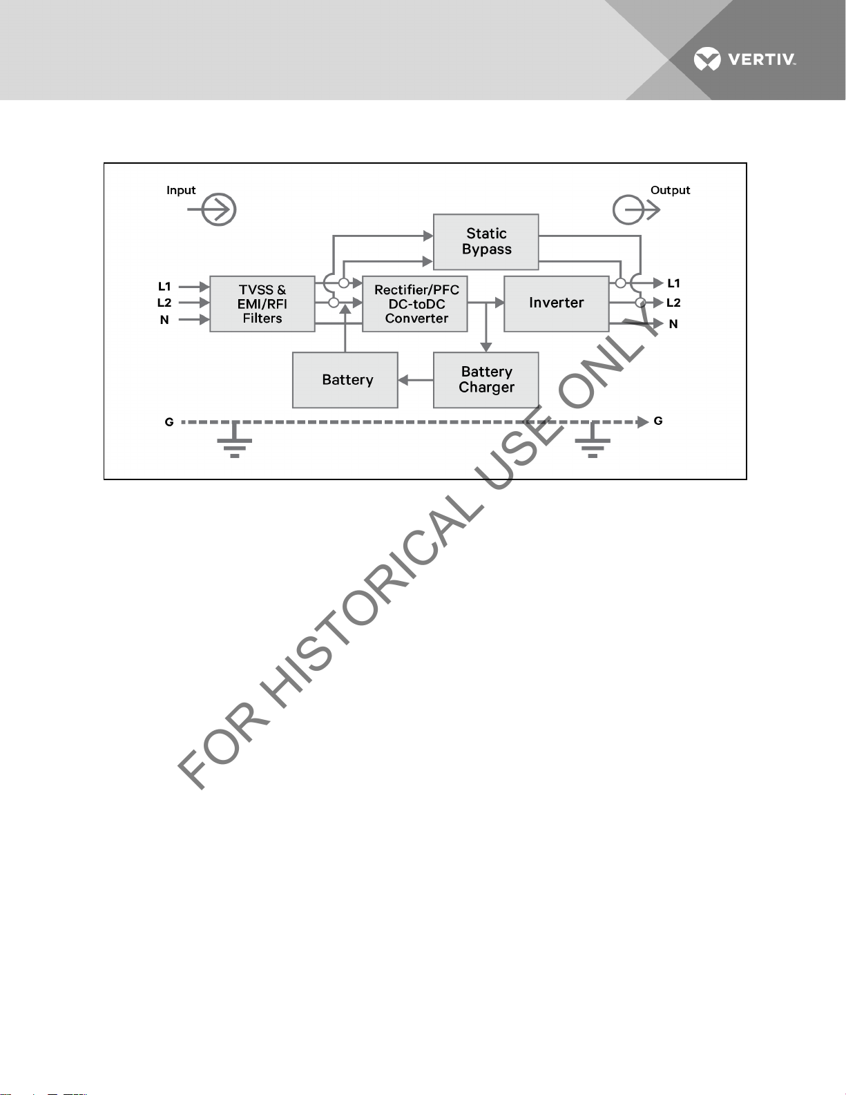
2 SYSTEM DESCRIPTION
FOR HISTORICAL USE ONLY
2.1 Transient Voltage Surge Suppression (TVSS) and EMI/RFI Filters
These UPS components provide surge protection and filter both electromagnetic interference (EMI) and radio frequency
interference (RFI). They minimize any surges or interference present in the utility line and keep the sensitive equipment
protected.
2.2 Rectifier/Power Factor Correction (PFC) Circuit
In normal operation, the rectifier/power factor correction (PFC) circuit converts utility AC power to regulated DC power for
use by the inverter while ensuring that the waveshape of the input current used by the UPS is near ideal. Extracting this
sinewave input current achieves two objectives:
• The utility power is used as efficiently as possible by the UPS.
• The amount of distortion reflected on the utility is reduced.
This results in cleaner power being available to other devices in the building not being protected by the Liebert GXT3.
2.3 Inverter
In normal operation, the inverter utilizes the DC output of the power factor correction circuit and inverts it into precise,
regulated sinewave AC power. Upon a utility power failure, the inverter receives its required energy from the battery
through the DC-to-DC converter. In both modes of operation, the UPS inverter is on-line and continuously generating clean,
precise, regulated AC output power.
2.4 Battery Charger
The battery charger utilizes energy from the utility power and precisely regulates it to continuously float charge the
batteries. The batteries are being charged whenever the Liebert GXT3 is connected to utility power.
2.5 DC-to-DC Converter
The DC-to-DC converter utilizes energy from the battery system and raises the DC voltage to the optimum operating
voltage for the inverter. This allows the inverter to operate continuously at its optimum efficiency and voltage, thus
increasing reliability.
Vertiv| Liebert® GXT3 ™ Installer/User Guide | 10

2.6 Battery
FOR HISTORICAL USE ONLY
The Liebert GXT3 utilizes valve-regulated, nonspillable, lead acid batteries. To maintain battery design life, operate the
UPS in an ambient temperature of 15°C to 25°C (59°F to 77°F). Optional external battery cabinets are available to extend
battery run times. For run times, see Table 12.8 on page63.
2.7 Dynamic Bypass
The Liebert GXT3 provides an alternate path for utility power to the connected load in the unlikely event of a UPS
malfunction. Should the UPS have an overload, overtemperature or any other UPS failure condition, the UPS automatically
transfers the connected load to bypass. Bypass operation is indicated by an audible alarm and illuminated amber Bypass
LED (other LEDs may be illuminated to indicate the diagnosed problem). To manually transfer the connected load from the
inverter to bypass, press the Standby/Manual Bypass button once and hold it for about 2 seconds.
NOTE: The bypass power path does NOT protect the connected equipment from disturbances in the utility supply.
Vertiv| Liebert® GXT3 ™ Installer/User Guide | 11

This page intentionally left blank.
FOR HISTORICAL USE ONLY
Vertiv| Liebert® GXT3 ™ Installer/User Guide | 12
3 MAJOR COMPONENTS
FOR HISTORICAL USE ONLY
The Liebert GXT3 is composed of three major assemblies to provide easier handling, installation and versatility.
3.1 Main Frame and Electronics
All models of the Liebert GXT3 are shipped without the internal batteries installed. Power distribution varies by model and
rating.
• Liebert GXT3 5000 and 6000VA models ship with a basic hardwire distribution box attached and ready to be
connected to the load (see Figure 3.2 on the next page).
• Liebert GXT3RTL630 ships with a power distribution box attached (see (Figure 3.4 on page15).
• Liebert GXT3 8000 and 10,000VA models with a cover plate installed over connections for any of several
optional power distribution boxes (see Figure 3.5 on page16).
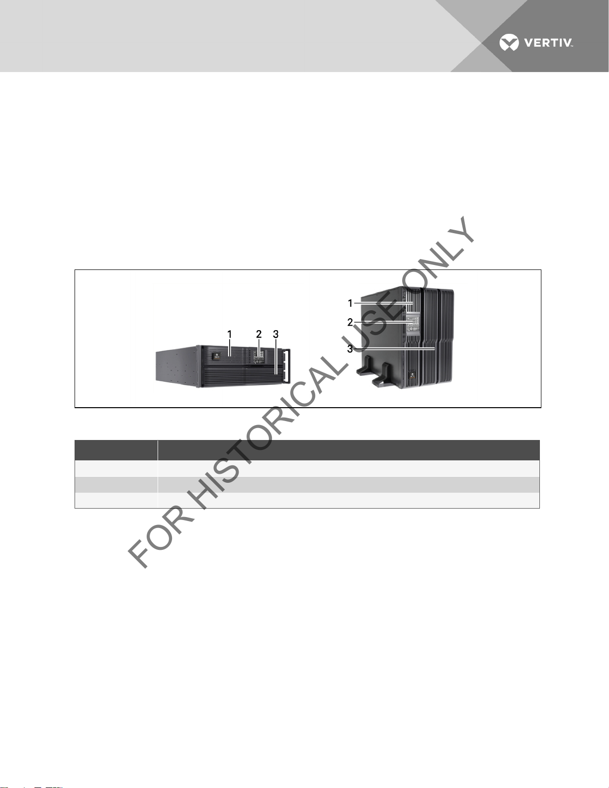
Figure 3.1 Liebert GXT3 front view—rack-mount and tower configurations
Table 3.1 GXT3 Front View Description
ITEM DESC RIPTION
1 Upper Bezel
2 Status Indicators and Controls
3 Lower Bezel and Battery Acc ess Door
Vertiv| Liebert® GXT3 ™ Installer/User Guide | 13
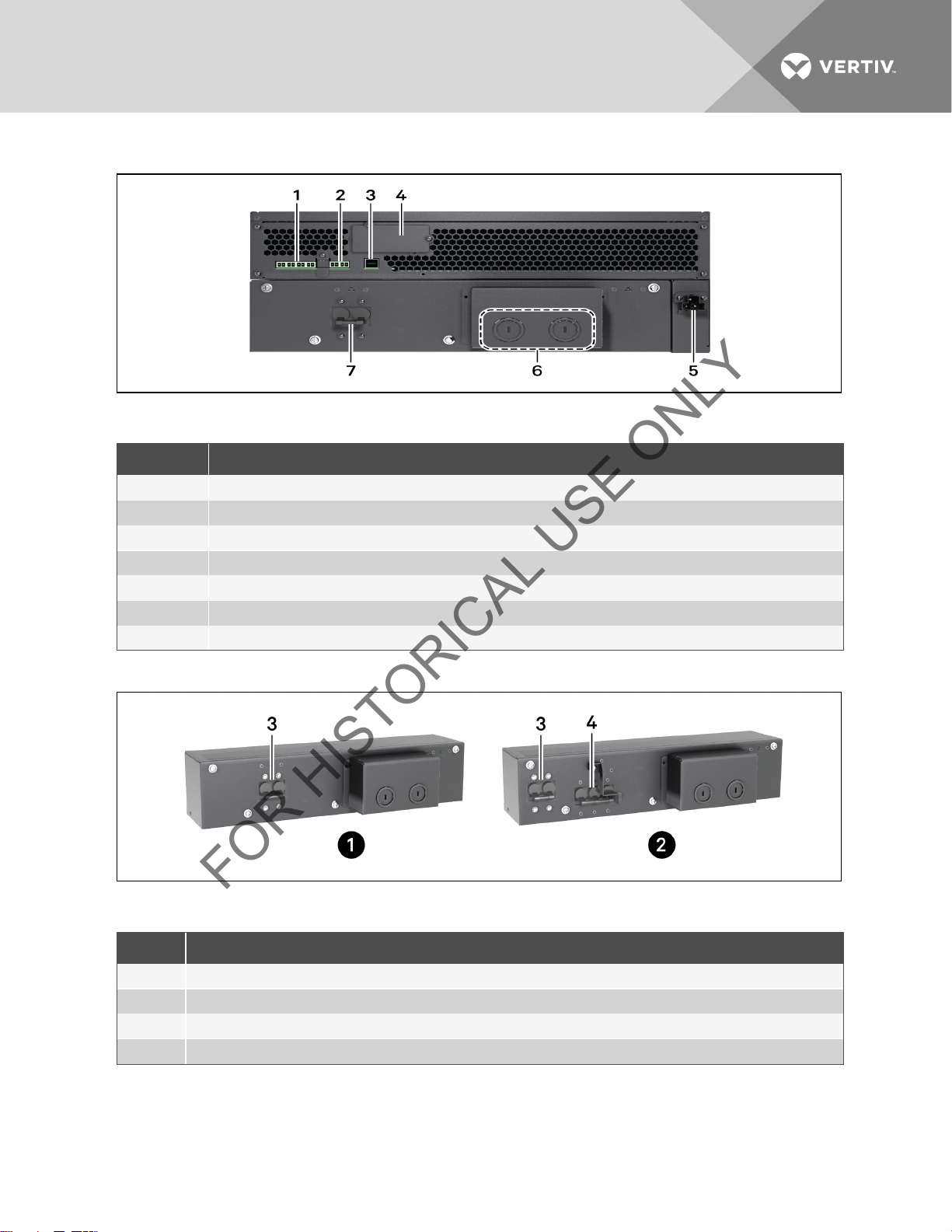
Figure 3.2 Liebert GXT3 5000VA and 6000VA rear view
FOR HISTORICAL USE ONLY
Table 3.2 GXT3 5000VA and 6000VA rear view
ITEM DESC RIPTION
1 Terminal Block Communication
2 REPO
3 USB Port
4 Liebert Intellislot Port
5 External Battery Connector
6 Knockouts for Hardwired PowerInput
7 Input Breaker
Figure 3.3 Input power hardwire boxes—5000 and 6000VA models
Table 3.3 Input Power Hardwire Boxes Descriptions
ITEM DESC RIPTIONS
1 PD2-HDWR 5000 and 6000VA models
2 PD2-HDWR-MBS - 5000 AND 6000VAmodels
3 Input Breaker
4 Maintenance Bypass Breaker
NOTE: Hardwire and hardwire/receptacle boxes that include a manual bypass switch permit AC power to continue to
flow from the utility input to the load while the box is removed from the UPS. For details, refer to Removable Power
Distribution Box on page 16.
Vertiv| Liebert® GXT3 ™ Installer/User Guide | 14
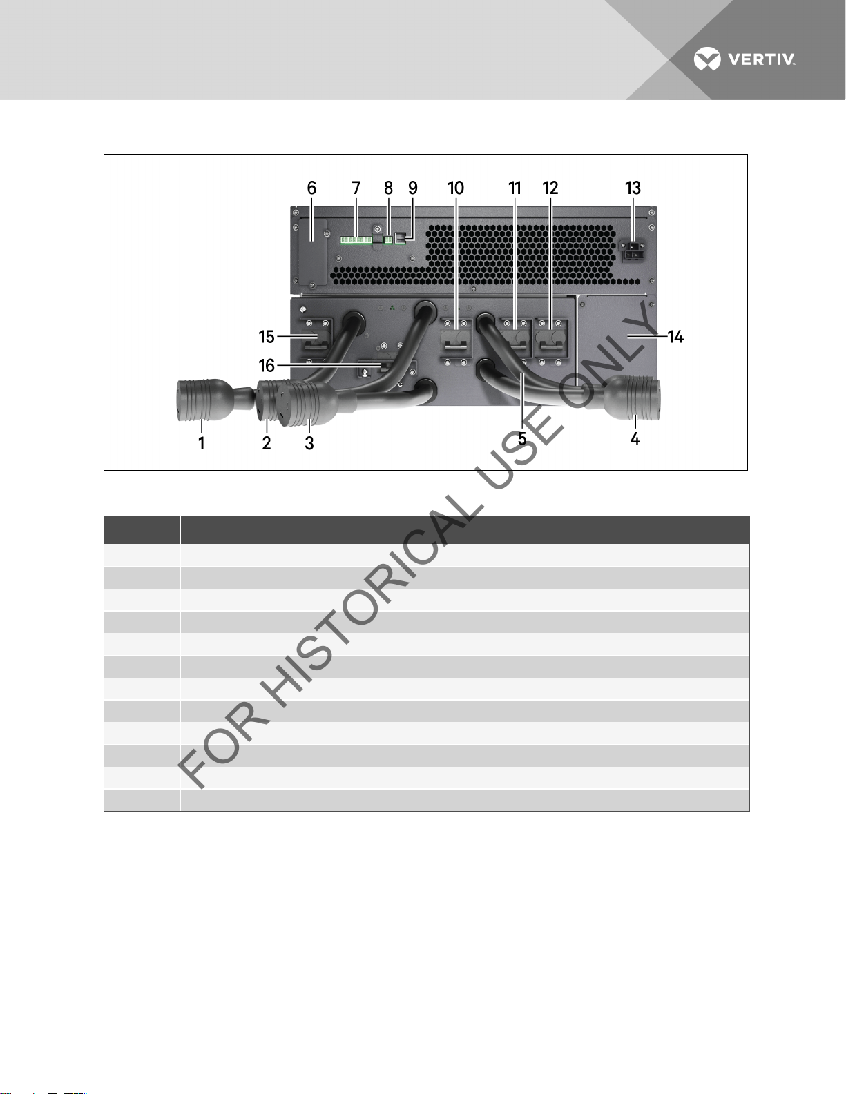
Figure 3.4 Liebert GXT3-6000RTL630, rear view
FOR HISTORICAL USE ONLY
Table 3.4 Liebert GXT3-6000RTL630 Rear View Descriptions
ITEM D ESCRIPTIONS
1-5 Connectors
6 Liebert Intellislot Port
7 Terminal Block Communications
8 REPO Connection Block
9 USB Port
10 Output Breaker f or L6-20R #2 and#3
11 Output Breaker f or L6-30R #4
12 Output Breaker f or L6-30R #5
13 External Battery Connector
14 IT Power Syst em Access Cover
15 Input Breaker for L6-30P #1
16 Maintenance Bypass Breaker
Vertiv| Liebert® GXT3 ™ Installer/User Guide | 15
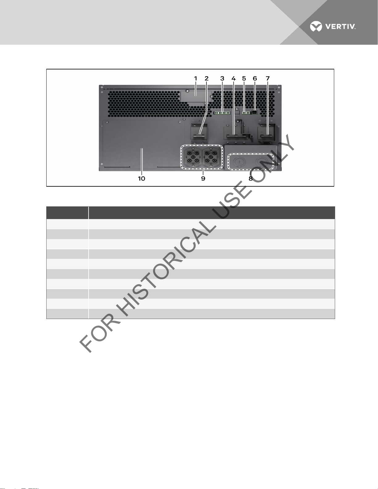
Figure 3.5 Liebert GXT3 8000VA and 10,000VA rear view
FOR HISTORICAL USE ONLY
Table 3.5 Liebert GXT3 8000VA and 10,000VA Rear View
ITEM DESC RIPTIONS
1 Liebert Intellislot Port
2 Output Breaker Switch
3 Terminal Block Communication
4 Maintenance Bypass Switch
5 REPO Connection Block
6 USB Port
7 Input Breaker Switch
8 Knockouts for Hardwired PowerInput
9 External Battery Connector
10 Cover f or Power Distribution Box Connections
3.2 Removable Power Distribution Box
The UPS is shipped with a power distribution pack installed. This box contains the UPS input circuit breaker.
Vertiv| Liebert® GXT3 ™ Installer/User Guide | 16
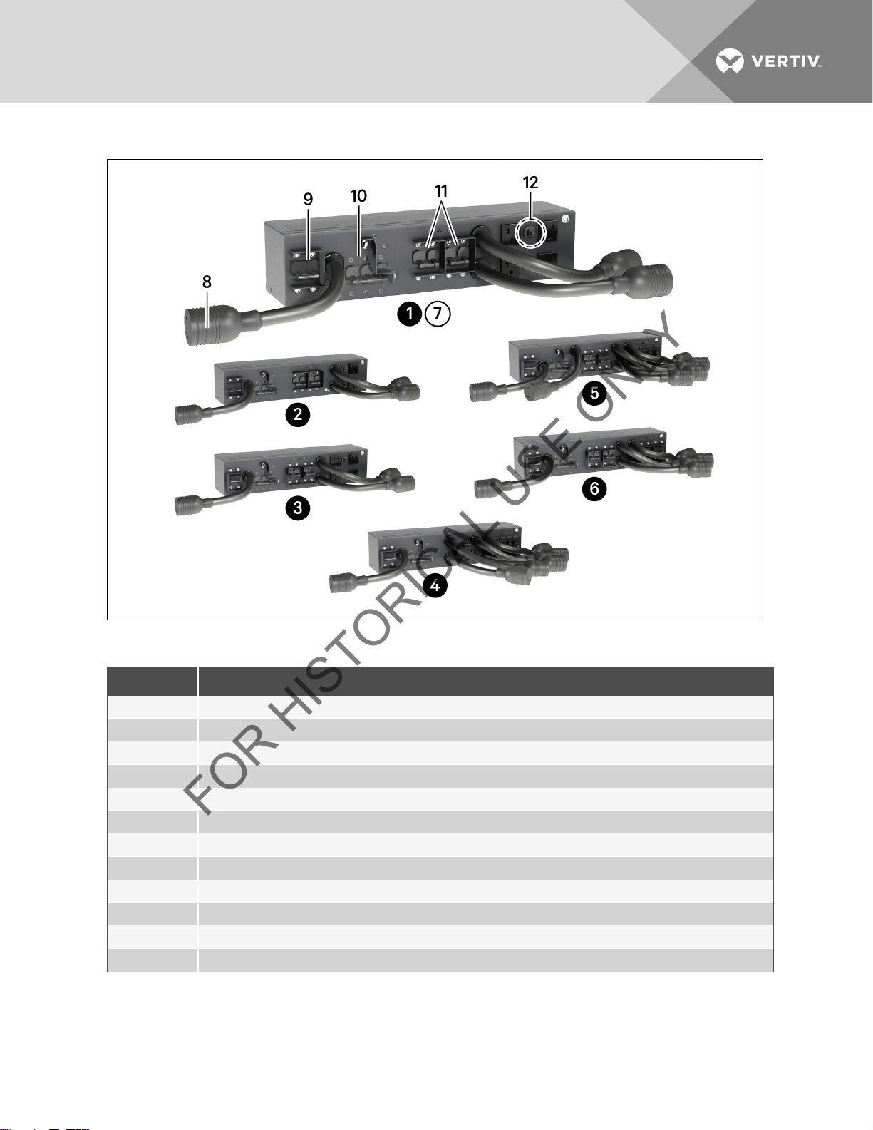
Figure 3.6 Power distribution models for 5000VA and 6000VA models of Liebert GXT3
FOR HISTORICAL USE ONLY
Table 3.6 Power Distribution Models for 5000VA and 6000VA Models of Liebert GXT3 Descriptions
ITEM DESC RIPTION
1 PD@-001 shown as example; similar features on other distribution boxes arranged differently
2 PD2-002 Receptacles: two 5-20R; two L6-20R
3 PD2-003 Receptacles: four 5-20R; two L6-30R
4 PD2-004 Receptacles: four L5-20R; t wo L5-30R
5 PD2-005 Receptacles: four L5-20R; t wo L6-30R
6 PD2-006 Receptacles: four L6-20R
7 PD2-001 Receptacles: four 5-20; one L14-30; oneL6-30R
8 L14-30 Input Power Connector
9 Input Power Breaker
10 Maintenance Bypass Breaker
11 Output Power Breakers for Pigtails
12 Push Button Output Power Breakers for Two L5-20 Receptacles (second push button breaker obscured)
Vertiv| Liebert® GXT3 ™ Installer/User Guide | 17
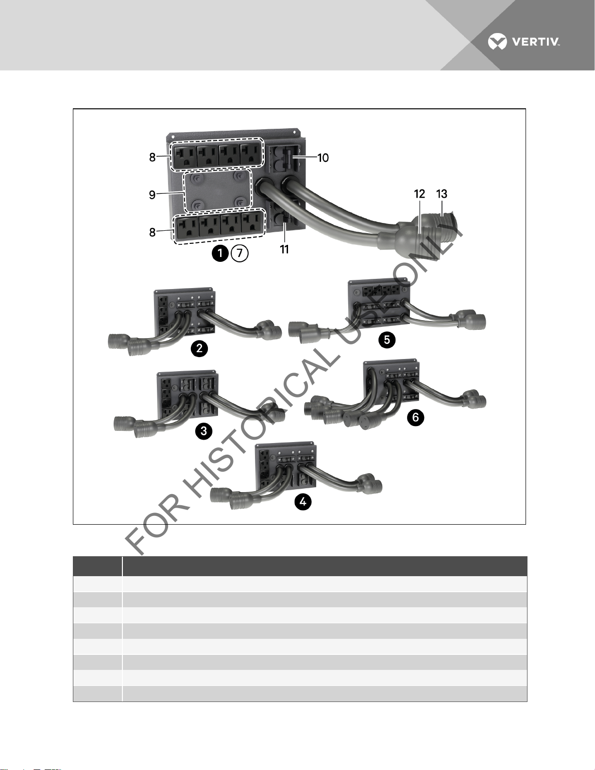
Figure 3.7 Power distribution models for 8000VA and 10,000VA models of Liebert GXT3
FOR HISTORICAL USE ONLY
Table 3.7 Power Distribution Models for 5000VA and 6000VA Models of Liebert GXT3
ITEM DESC RIPTION
1 PD2-101 Receptacles: two L6-30; eight 5-20R
2 PD2-102 Receptacles: four L6-20R four 5-20R
3 PD2-103 Receptacles: four L6-30R four 5-20R
4 PD2-104 Receptacles: four 5-20R two L6-30R two L6-20R
5 PD2-105 Receptacles: four 5-20R two L5-30R two L5-20R
6 PD2-106 Receptacles: four L6-20R four L5-20R
7 Similar features on other distributionboxes arranged differently
8 5-20R Output Receptacles
Vertiv| Liebert® GXT3 ™ Installer/User Guide | 18
ITEM DESC RIPTION
FOR HISTORICAL USE ONLY
9 Push Button Circuit Breakers for 5-20R Receptacles
10 Output Circuit Breaker Swit ch f or L6-30R Pigtail #1
11 Output Circuit Breaker Swit ch f or L6-30R Pigtail #2
12 L6-30R Output Receptacles
13 L6-30R Output Receptacles
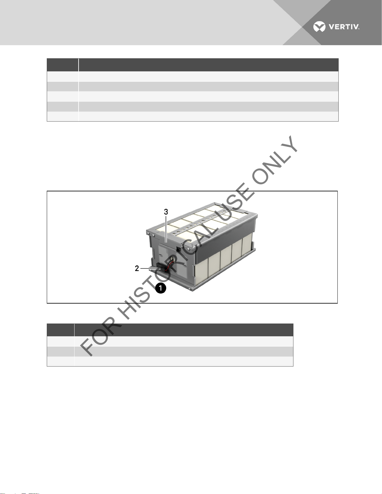
3.3 Internal Battery Packs
The UPS has two internal battery packs behind a battery access door on the front of the unit. Each internal battery pack is
fitted with a connector to link to the UPS.
Figure 3.8 Internal battery pack features
Table 3.8 Internal Battery Pack Feature Descriptions
ITEM DESCRIPTION
1 Front of Battery Pack
2 Battery Connector
3 Battery Handles
NOTE: Liebert GXT3 8000 and 10,000VA battery packs shown; 5000 and 6000VA battery packs have same features.
Vertiv| Liebert® GXT3 ™ Installer/User Guide | 19

This page intentionally left blank.
FOR HISTORICAL USE ONLY
Vertiv| Liebert® GXT3 ™ Installer/User Guide | 20

4 WHAT’S INCLUDED
FOR HISTORICAL USE ONLY
The Liebert GXT3 is shipped with the following items:
• Terminal Block Communication terminals
• Compact disc with:
• Liebert MultiLink
• Configuration program
• User manual (electronic version)
• USB cable, one; 2m (6-1/2 ft.) long
• Rack handles with mounting hardware
• Power Distribution Box, installed on Liebert GXT3
• Plastic tower set, one
• Warnings, safety instructions booklet and WEEE recycling sheet (ISO 14001 compliance)
NOTE: The Liebert GXT3 External Battery Cabinet shipping package includes one battery cabinet, two spacers for the
5000 and 6000VA models and four spacers for the 8000 and 10000VA models for tower configuration and one DC
power cable.
®
Vertiv| Liebert® GXT3 ™ Installer/User Guide | 21
 Loading...