

Page 1

Liebert®
EXM™ MBC™
User Manual—10-200kVA, 208/120V and 220/127V, 60Hz
Page 2

The information contained in this document is subject to change
without notice and may not be suitable for all applications. While
every precaution has been taken to ensure the accuracy and
completeness of this document, Vertiv assumes no responsibility
and disclaims all liability for damages resulting from use of this
information or for any errors or omissions. Refer to other local
practices or building codes as applicable for the correct methods,
tools, and materials to be used in performing procedures not
specifically described in this document.
The products covered by this instruction manual are manufactured
and/or sold by Vertiv This document is the property of Vertiv and
contains confidential and proprietary information owned by Vertiv.
Any copying, use or disclosure of it without the written permission of
Vertiv is strictly prohibited.
Names of companies and products are trademarks or registered
trademarks of the respective companies. Any questions regarding
usage of trademark names should be directed to the original
manufacturer.
Technical Support Site
If you encounter any installation or operational issues with your product, check the pertinent
section of this manual to see if the issue can be resolved by following outlined procedures.
Visit https://www.VertivCo.com/en-us/support/ for additional assistance.
Page 3

TABLE OF CONTENTS
IMPORTANT SAFETY INSTRUCTIONS . . . . . . . . . . . . . . . . . . . . . . . . . . . . . . . . . . . . . . 1
SAVE THESE INSTRUCTIONS . . . . . . . . . . . . . . . . . . . . . . . . . . . . . . . . . . . . . . . . . . . . . . . 1
1.0 MECHANICAL INSTALLATION . . . . . . . . . . . . . . . . . . . . . . . . . . . . . . . . . . . . . . . . 3
1.1 Introduction. . . . . . . . . . . . . . . . . . . . . . . . . . . . . . . . . . . . . . . . . . . . . . . . . . . . . . . . . . . . . . . . . . . . . . . . . . . . . . 3
1.2 Preliminary Checks . . . . . . . . . . . . . . . . . . . . . . . . . . . . . . . . . . . . . . . . . . . . . . . . . . . . . . . . . . . . . . . . . . . . . . 3
1.3 Environmental Considerations. . . . . . . . . . . . . . . . . . . . . . . . . . . . . . . . . . . . . . . . . . . . . . . . . . . . . . . . . . . 4
1.3.1 Room . . . . . . . . . . . . . . . . . . . . . . . . . . . . . . . . . . . . . . . . . . . . . . . . . . . . . . . . . . . . . . . . . . . . . . . . . . . . . . . . . . . . . 4
1.3.2 Storage . . . . . . . . . . . . . . . . . . . . . . . . . . . . . . . . . . . . . . . . . . . . . . . . . . . . . . . . . . . . . . . . . . . . . . . . . . . . . . . . . . . 4
1.4 Positioning. . . . . . . . . . . . . . . . . . . . . . . . . . . . . . . . . . . . . . . . . . . . . . . . . . . . . . . . . . . . . . . . . . . . . . . . . . . . . . . 4
1.4.1 Moving the Cabinets . . . . . . . . . . . . . . . . . . . . . . . . . . . . . . . . . . . . . . . . . . . . . . . . . . . . . . . . . . . . . . . . . . . . . 4
1.4.2 Clearances . . . . . . . . . . . . . . . . . . . . . . . . . . . . . . . . . . . . . . . . . . . . . . . . . . . . . . . . . . . . . . . . . . . . . . . . . . . . . . . 5
1.4.3 Floor Installation/Anchoring. . . . . . . . . . . . . . . . . . . . . . . . . . . . . . . . . . . . . . . . . . . . . . . . . . . . . . . . . . . . . . 5
1.5 Cable Entry . . . . . . . . . . . . . . . . . . . . . . . . . . . . . . . . . . . . . . . . . . . . . . . . . . . . . . . . . . . . . . . . . . . . . . . . . . . . . . 5
1.6 Power Cables . . . . . . . . . . . . . . . . . . . . . . . . . . . . . . . . . . . . . . . . . . . . . . . . . . . . . . . . . . . . . . . . . . . . . . . . . . . . 5
1.6.1 Power Cable Connection Procedure. . . . . . . . . . . . . . . . . . . . . . . . . . . . . . . . . . . . . . . . . . . . . . . . . . . . . . 7
2.0 INSTALLATION DRAWINGS . . . . . . . . . . . . . . . . . . . . . . . . . . . . . . . . . . . . . . . . . . 10
3.0 SPECIFICATIONS . . . . . . . . . . . . . . . . . . . . . . . . . . . . . . . . . . . . . . . . . . . . . . . . . . . . .35
3.1 Electrical Characteristics . . . . . . . . . . . . . . . . . . . . . . . . . . . . . . . . . . . . . . . . . . . . . . . . . . . . . . . . . . . . . . . 37
3.2 Torque Requirements. . . . . . . . . . . . . . . . . . . . . . . . . . . . . . . . . . . . . . . . . . . . . . . . . . . . . . . . . . . . . . . . . . . 41
FIGURES
Figure 1 Cabinet arrangement—Liebert EXM UPS, battery cabinets, maintenance bypass cab-
inet6
Figure 2 One-line diagram, single-input Liebert EXM 10-40kVA UPS with three-breaker Lieb-
ert EXM
MBC and input/output transformer cabinet. . . . . . . . . . . . . . . . . . . . . . . . . . . . . . . . . . . . . . . . . 10
Figure 3 One-line diagram, single-input Liebert EXM 10-200kVA UPS with three-breaker Lieb-
ert
EXM MBC . . . . . . . . . . . . . . . . . . . . . . . . . . . . . . . . . . . . . . . . . . . . . . . . . . . . . . . . . . . . . . . . . . . . . . . . . . . 11
Figure 4 One-line diagram, dual-input Liebert EXM 10-100kVA with two-breaker Liebert MBC
12
Figure 5 One-line diagram, dual-input Liebert EXM 10-100kVA UPS with four-breaker Liebert
EXM MBC
and input isolation transformer cabinet . . . . . . . . . . . . . . . . . . . . . . . . . . . . . . . . . . . . . . . . . . . . . 13
Figure 6 One-line diagram, dual-input Liebert EXM 10-200kVA UPS with three-breaker Lieb-
ert
EXM MBC . . . . . . . . . . . . . . . . . . . . . . . . . . . . . . . . . . . . . . . . . . . . . . . . . . . . . . . . . . . . . . . . . . . . . . . . . . . 14
Figure 7 One-line diagram, dual input Liebert EXM 10-200kVA with four-breaker Liebert MBC
15
Figure 8 Bend radius—Neutral and ground wires through bottom feed, 10-40kVA system . . 15
Figure 9 Main components—200mm Liebert EXM MBC, two to four breakers, 10-40kVA sys-
tem16
Vertiv™|Liebert® EXM™ MBC Installation Manual | i
Page 4

Figure 10 Main components—300mm Liebert EXM MBC, two to four breakers, 60-100kVA sys-
tem17
Figure 11 Main components—600mm Liebert EXM MBC, two breakers, 120-200kVA system 18
Figure 12 Main components—600mm Liebert EXM MBC, three to four breakers, 120-160kVA
system18
Figure 13 Main components—800mm Liebert EXM MBC, three or four breakers, 160-200kVA
system19
Figure 14 Outline drawing—200mm Liebert EXM MBC, two to four breakers, 10-40kVA system
20
Figure 15 Outline drawing—300mm Liebert EXM MBC, two to four breakers, 60-100kVA sys-
tem21
Figure 16 Outline drawing—600mm Liebert EXM MBC 120-200kVA system . . . . . . . . . . . . . . . . .22
Figure 17 Outline drawing—800mm Liebert EXM MBC 160-200kVA system . . . . . . . . . . . . . . . . . 23
Figure 18 Terminal details—200mm Liebert EXM MBC, two to four breakers, 10-40kVA system
24
Figure 19 Terminal details—300mm Liebert EXM MBC, two to four breakers, 60-100kVA sys-
tem25
Figure 20 Terminal details—600mm Liebert EXM MBC, two breakers, 120-200kVA system . .26
Figure 21 Terminal details—600mm Liebert EXM MBC, three breakers, 120-160kVA system. 27
Figure 22 Terminal details—600mm Liebert EXM MBC, four breakers, 120-160kVA system . .28
Figure 23 Terminal details—800mm Liebert EXM MBC, three breakers, 160-200kVA system 29
Figure 24 Terminal details—800mm Liebert EXM MBC, four breakers, 160-200kVA system. .30
Figure 25 Control wiring diagram, Liebert EXM MBC, two to four breakers, with interlock . . . . 31
Figure 26 Solenoid key release unit, 200mm Liebert EXM MBC . . . . . . . . . . . . . . . . . . . . . . . . . . . . . . .32
Figure 27 Solenoid key release unit, 300mm Liebert EXM MBC . . . . . . . . . . . . . . . . . . . . . . . . . . . . . . .33
Figure 28 Solenoid key release unit, 600mm Liebert EXM MBC . . . . . . . . . . . . . . . . . . . . . . . . . . . . . . .34
Figure 29 Solenoid key release unit, 800mm Liebert EXM MBC . . . . . . . . . . . . . . . . . . . . . . . . . . . . . . .34
TAB LES
Table 1 Control wiring for Liebert EXM UPS to Liebert EXM MBC. . . . . . . . . . . . . . . . . . . . . . . . . . . . 8
Table 2 Breaker configuration—200mm Liebert EXM MBC two to four breakers, 10-40kVA
system. . . . . . . . . . . . . . . . . . . . . . . . . . . . . . . . . . . . . . . . . . . . . . . . . . . . . . . . . . . . . . . . . . . . . . . . . . . . . . . 16
Table 3 Terminal block details—200mm Liebert EXM MBC, two to four breakers, 10-40kVA
system. . . . . . . . . . . . . . . . . . . . . . . . . . . . . . . . . . . . . . . . . . . . . . . . . . . . . . . . . . . . . . . . . . . . . . . . . . . . . . . 16
Table 4 Breaker configuration, 300mm Liebert EXM MBC, two to four breakers, 60-100kVA
system. . . . . . . . . . . . . . . . . . . . . . . . . . . . . . . . . . . . . . . . . . . . . . . . . . . . . . . . . . . . . . . . . . . . . . . . . . . . . . . 17
Table 5 Terminal block details—300mm Liebert EXM MBC, two to four breakers, 60-100kVA
system. . . . . . . . . . . . . . . . . . . . . . . . . . . . . . . . . . . . . . . . . . . . . . . . . . . . . . . . . . . . . . . . . . . . . . . . . . . . . . . 17
Table 6 Breaker configuration—200mm Liebert EXM MBC, two to four breakers, 10-40kVA
system. . . . . . . . . . . . . . . . . . . . . . . . . . . . . . . . . . . . . . . . . . . . . . . . . . . . . . . . . . . . . . . . . . . . . . . . . . . . . . .24
Table 7 Breaker configuration—300mm Liebert EXM MBC, two to four breakers, 60-100kVA
system. . . . . . . . . . . . . . . . . . . . . . . . . . . . . . . . . . . . . . . . . . . . . . . . . . . . . . . . . . . . . . . . . . . . . . . . . . . . . . .25
Table 8 Terminal block details—300mm Liebert EXM MBC, two to four breakers, 60-100kVA
system. . . . . . . . . . . . . . . . . . . . . . . . . . . . . . . . . . . . . . . . . . . . . . . . . . . . . . . . . . . . . . . . . . . . . . . . . . . . . . .25
Table 9 Terminal block details—200mm Liebert EXM MBC, two to four breakers, 10-40kVA
system. . . . . . . . . . . . . . . . . . . . . . . . . . . . . . . . . . . . . . . . . . . . . . . . . . . . . . . . . . . . . . . . . . . . . . . . . . . . . . .25
Table 10 Liebert EXM MBC specifications . . . . . . . . . . . . . . . . . . . . . . . . . . . . . . . . . . . . . . . . . . . . . . . . . . . .35
Vertiv™|Liebert® EXM™ MBC Installation Manual | ii
Page 5

Table 11 Dimensions for Liebert EXM UPS with Liebert EXM MBC . . . . . . . . . . . . . . . . . . . . . . . . . . .35
Table 12 Weights—Liebert EXM UPS, 10-40kVA, and 200mm Liebert EXM MBC . . . . . . . . . . . .36
Table 13 Weights—Liebert EXM UPS, 60-100kVA, and 300mm Liebert EXM MBC . . . . . . . . . .36
Table 14 Additional weight for Liebert EXM 10-40kVA UPS with internal batteries *. . . . . . . . .36
Table 15 Liebert EXM MBC input currents, single input, main . . . . . . . . . . . . . . . . . . . . . . . . . . . . . . . . 37
Table 16 Liebert EXM MBC input currents, dual input, rectifier. . . . . . . . . . . . . . . . . . . . . . . . . . . . . . .38
Table 17 Liebert EXM MBC input currents, dual input, bypass . . . . . . . . . . . . . . . . . . . . . . . . . . . . . . .39
Table 18 Recommended lug sizes (compression type) M10, 3/8" bolt . . . . . . . . . . . . . . . . . . . . . . . 40
Table 19 Liebert EXM MBC output currents . . . . . . . . . . . . . . . . . . . . . . . . . . . . . . . . . . . . . . . . . . . . . . . . . 40
Table 20 Recommended lug sizes (Compression Type) M12, 1/2" bolt . . . . . . . . . . . . . . . . . . . . . . . . 41
Table 21 Busbar torque for power wiring . . . . . . . . . . . . . . . . . . . . . . . . . . . . . . . . . . . . . . . . . . . . . . . . . . . . . 41
Table 22 Terminal block torque with compression lugs for control wiring . . . . . . . . . . . . . . . . . . . . 41
Vertiv™|Liebert® EXM™ MBC Installation Manual | iii
Page 6

Vertiv™|Liebert® EXM™ MBC Installation Manual | iv
Page 7
IMPORTANT SAFETY INSTRUCTIONS
SAVE THESE INSTRUCTIONS
This manual contains important instructions that should be followed during installation of your
Liebert EXM Maintenance Bypass Cabinet MBC).
Read this manual thoroughly before working with the Maintenance Bypass Cabinet. Retain this
manual for use by installing personnel.
WARNING
Risk of moving heavy units and tipping hazard. Can cause equipment damage, injury and
death.
Exercise extreme care when handling cabinets to avoid equipment damage or injury to
personnel. The Liebert EXM MBC’s weight ranges from 198 to 700 lb. (89.9 to 317.5 kg).
Locate center of gravity symbols and determine unit weight before handling each
cabinet. Test lift and balance the cabinets before transporting. Maintain minimum tilt from
vertical at all times.
Slots at the base of the cabinets are intended for forklift use. Base slots will support the unit
only if the forks are completely beneath the unit.
In case of fire involving electrical equipment, use only carbon dioxide fire extinguishers or
those approved for use in fighting electrical fires.
Extreme caution is required when performing maintenance.
Be constantly aware that the system contains high DC as well as AC voltages.
Check for voltage with both AC and DC voltmeters prior to making contact.
AVERTISSEMENT
Le centre de gravité élevé des appareils présente un risque de renversement lors des
déplacements pouvant entraîner des dommages matériels, des blessures et même la mort.
Faites preuve d’une extrême prudence lors de la manutention des armoires afin d’éviter de
les endommager ou de blesser le personnel. Les armoires de dérivation d’entretien EXM de
Liebert pèsent de 198 à 700 lb (de 89.9 à 317.5 kg).
Identifiez les symboles de centre de gravité et déterminez le poids de l’appareil avant
de manipuler chaque armoire. Testez le levage et l’équilibre des armoires avant de
transporter l’appareil. Maintenez en tout temps l’inclinaison verticale minimale.
Les fentes situées à la base des armoires sont conçues pour utiliser le chariot élévateur.
Les fentes situées à la base peuvent soutenir le système seulement si les fourches se
trouvent complètement sous le système.
En cas d’incendie associé à du matériel électrique, n’utilisez que des extincteurs à dioxyde
de carbone ou homologués pour la lutte contre les incendies d’origine électrique.
Les opérations d’entretien requièrent une extrême prudence.
Soyez toujours conscient du fait que le système contient des tensions c.c. et c.a. élevées.
Vérifiez les tensions avec des voltmètres c.a. et c.c. avant d’établir tout contact.
Vertiv™|Liebert® EXM™ MBC Installation Manual | 1
Page 8

.
WARNING
Risk of arc flash and electric shock. Can cause equipment damage, injury and death.
Under typical operation and with all doors closed, only normal safety precautions are
necessary. The area around the system should be kept free of puddles of water, excess
moisture and debris.
Special safety precautions are required for procedures involving handling, installation and
maintenance of the Maintenance Bypass Cabinet. Observe all safety precautions in this
manual before handling or installing the Maintenance Bypass Cabinet. Observe all
precautions in the Operation and Maintenance Manual, before as well as during
performance of all maintenance procedures.
This equipment contains circuits that are energized with high voltage. Only test equipment
designed for troubleshooting should be used. This is particularly true for oscilloscopes.
Always check with an AC and DC voltmeter to ensure safety before making contact or
using tools. Even when the power is turned Off, dangerously high potential electric charges
may exist.
All power and control wiring should be installed by a qualified electrician. All power and
control wiring must comply with the NEC and applicable local codes.
ONLY properly trained and qualified personnel should perform maintenance on the
Maintenance Bypass Cabinet. When performing maintenance with any part of the equipment
under power, service personnel and test equipment should be standing on rubber mats. The
service personnel should wear insulating shoes for isolation from direct contact with the floor
ground.
One person should never work alone, even if all power is removed from the equipment. A
second person should be standing by to assist and summon help in case of an accident.
Vertiv™|Liebert® EXM™ MBC Installation Manual | 2
Page 9

AVERTISSEMENT
Risque d’arc ou de décharge électrique pouvant entraîner des dommages matériels, des
blessures et même la mort.
Les précautions de sécurité habituelles suffisent lorsque le système est en mode de
fonctionnement normal et que toutes les portes sont fermées. La zone entourant le
système doit être exempte de flaques d’eau, d’humidité excessive et de débris.
Des précautions de sécurité spéciales sont requises pour les procédures associées à la
manutention, à l’installation et à l’entretien de l’armoire de dérivation d’entretien. Observez
toutes les précautions de sécurité décrites dans le présent manuel avant de manipuler ou
d’installer l’armoire de dérivation d’entretien. Observez également toutes les précautions
décrites dans le manuel d’utilisation et d’entretien, avant et pendant toutes les procédures
d’entretien.
Cet équipement comporte des circuits à haute tension. Seuls des équipements d’essai
conçus pour le dépannage doivent être utilisés. Cette mise en garde couvre notamment les
oscilloscopes. Utilisez toujours un voltmètre c.a. et c.c. pour vérifier les tensions avant
d’établir un contact ou d’utiliser des appareils. Des tensions dangereusement élevées
peuvent demeurer dans le système même une fois l’alimentation coupée.
Tous les câbles d’alimentation et de contrôle doivent être installés par un électricien
qualifié. Tous les câbles d’alimentation et de contrôle doivent être conformes au Code
national de l’électricité des États-Unis (NEC) et ainsi qu’aux codes locaux en vigueur.
L’entretien de l’armoire de dérivation d’entretien ne doit être confié qu’à des professionnels
qualifiés et dûment formés. Les responsables de l’entretien et l’équipement d’essai doivent
reposer sur des tapis de caoutchouc lors de toute intervention sur une pièce d’équipement
sous tension. Les responsables de l’entretien doivent porter des chaussures isolantes pour
prévenir tout contact direct avec le plancher.
Une personne ne devrait jamais travailler seule, même si toute l’alimentation de
l’équipement est coupée. Une deuxième personne devrait toujours être présente pour
porter assistance ou chercher de l’aide en cas d’accident.
Vertiv™|Liebert® EXM™ MBC Installation Manual | 3
Page 10

1.0 MECHANICAL INSTALLATION
1.1 Introduction
This section describes the requirements that must be taken into account when planning the
positioning and cabling of the Liebert EXM MBC.
This chapter is a guide to general procedures and practices that should be observed by the
installing engineer. The particular conditions of each site will determine the applicability of such
procedures.
WARNING
Risk of arc flash and electric shock. Can cause equipment damage, injury and death.
Installation must be performed only by properly trained and qualified personnel wearing
appropriate safety clothing.
Eye protection should be worn to prevent injury from accidental electrical arcs. Remove
rings, watches and all other metal objects. Only use tools with insulated handles. Wear
rubber gloves.
AVERTISSEMENT
Risque d’arc ou de décharge électrique pouvant entraîner des dommages matériels, des
blessures et même la mort.
L’installation ne doit être confiée qu’à des professionnels qualifiés et dûment formés
portant des vêtements de sécurité adéquats.
Des lunettes de sécurité doivent être portées afin de prévenir les blessures en cas d’arcs
accidentels. Retirez montre, bagues et tout autre objet métallique. Utilisez uniquement des
outils dont le manche est isolé. Portez des gants de protection en caoutchouc.
NOTICE
Risk of improper installation. Can cause equipment damage and void warranty.
The Liebert EXM MBC should be installed by a qualified engineer in accordance with the information
contained in this chapter
All equipment not referred to in this manual is shipped with details of its own mechanical and electrical
installation.
Do not apply electrical power to the UPS equipment before the arrival of the commissioning engineer.
1.2 Preliminary Checks
Before installing the Liebert EXM MBC, carry out the following preliminary checks:
• Visually examine the equipment for transit damage, both internally and externally. Report any damage to
the shipper immediately.
• Verify that the correct equipment is being installed. The equipment supplied has an identification tag on
the back of the main door reporting: the type, size and main calibration parameters of the UPS.
• Verify that the room satisfies the environmental conditions stipulated in the equipment specifications,
paying particular attention to the ambient temperature and air exchange system.
Vertiv™|Liebert® EXM™ MBC Installation Manual | 4
Page 11

1.3 Environmental Considerations
1.3.1 Room
The Liebert EXM MBC is intended for indoor installation and should be located in a cool, dry,
clean-air environment with adequate ventilation to keep the ambient temperature within the
specified operating range (see 3.0 - Specifications).
All models of the Liebert EXM MBC are convection-cooled. To permit air to enter and exit and
prevent overheating or malfunctioning, do not cover the ventilation openings.
When bottom entry is used, the conduit plate can be removed and punched and replaced. The
bottom conduit plate must be replaced for proper airflow. If necessary to cool the room, install a
system of room extractor fans.
NOTE
The Liebert EXM MBC is suitable for mounting only on concrete and other noncombustible
surfaces.
1.3.2 Storage
Should the equipment not be installed immediately, it must be stored in a room for protection
against excessive humidity and or heat sources (see Tab le 1 0).
1.4 Positioning
The cabinet is structurally designed to handle lifting from the base.
Access to the power terminals, auxiliary terminals blocks and power switches is from the top and
sides.
The top and side removable panels are secured to the chassis by screws. The side panel can be
removed for access to the power connections bars, auxiliary terminal blocks and power isolators.
1.4.1 Moving the Cabinets
The route to be travelled between the point of arrival and the unit’s position must be planned to
make sure that all passages are wide enough for the unit and that floors are capable of supporting
its weight (for instance, check that doorways, lifts, ramps, etc. are adequate and that there are no
impassable corners or changes in the level of corridors).
Ensure that the cabinet weight is within the designated surface weight loading (kg/cm2) of any
handling equipment. See Ta bl e 12 for the weight of the Liebert EXM MBC 200mm, 300mm,
600mm, and 800mm models. Tab le s 11 through 14 provide detailed dimension and weight
information for the Liebert EXM UPS and Liebert EXM MBC when they are bolted together and
shipped as a system.
Ensure that any lifting equipment used in moving the cabinet has sufficient lifting capacity.
The Liebert EXM MBC can be handled by means of a fork lift or similar equipment. For operations
with a fork lift, refer to installation drawings in 2.0 - Installation Drawings.
Because the weight distribution in the cabinet is uneven, use extreme care during handling and
transporting.
When moving the unit by forklift, care must be taken to protect the panels. Do not exceed a
15-degree tilt with the forklift.
Vertiv™|Liebert® EXM™ MBC Installation Manual | 5
Page 12

Handling the unit with straps is not authorized.
WARNING
Risk of moving heavy units and tipping hazard. Can cause equipment damage, injury and
death.
Exercise extreme care when handling cabinets to avoid equipment damage or injury to
personnel. The Liebert EXM MBC’s weight ranges from 198 to 700 lb. (89.8 to 317.5 kg).
Locate center of gravity symbols and determine unit weight before handling each
cabinet. Test lift and balance the cabinets before transporting. Maintain minimum tilt from
vertical at all times.
AVERTISSEMENT
Le centre de gravité élevé des appareils présente un risque de renversement lors des
déplacements pouvant entraîner des dommages matériels, des blessures et même la mort.
Faites preuve d’une extrême prudence lors de la manutention des armoires afin d’éviter de
les endommager ou de blesser le personnel. Les armoires de dérivation d’entretien EXM de
Liebert pèsent de 198 à 700 lb (de 89.8 à 317.5 kg).
Identifiez les symboles de centre de gravité et déterminez le poids de l’appareil avant de
manipuler chaque armoire. Testez le levage et l’équilibre des armoires avant de transporter
l’appareil. Maintenez en tout temps l’inclinaison verticale minimale.
1.4.2 Clearances
Liebert EXM MBC’s have no ventilation grilles at either side or at the rear. Clearance around the
front of the equipment should be sufficient to enable free passage of personnel with the doors
fully opened. It is important to leave a distance of 24" (610mm) between the top of the cabinet and
any overhead obstacles to permit adequate circulation of air coming out of the unit.
1.4.3 Floor Installation/Anchoring
The installation diagrams in 2.0 - Installation Drawings of this manual identify the location of the
holes in the base plate through which the equipment can be bolted to the floor. If the equipment
is to be located on a raised floor it should be mounted on a pedestal suitably designed to accept
the equipment point loading.
1.5 Cable Entry
Cables can enter the Liebert EXM MBC from the bottom or top.
1.6 Power Cables
The Liebert EXM MBC requires both power and control cabling once it has been mechanically
installed. All control cables must be separate from the power cables. Run control cables in metal
conduits or metal ducts that are electrically bonded to the cabinets they are connected to.
The cable design must comply with the voltages and currents provided in Ta bl es 1 5 through 17,
follow local wiring practices and take into consideration the environmental conditions
(temperature and physical support media).
Vertiv™|Liebert® EXM™ MBC Installation Manual | 6
Page 13

For cable entry locations, refer to Figures 14 and 15.
WARNING
Risk of electric shock. Can cause equipment damage, injury and death.
Before cabling up the cabinet, ensure that you are aware of the location and operation of
the external isolators that connect the input/bypass supply.
Check that these supplies are electrically isolated, and post any necessary warning signs to
prevent their inadvertent operation.
AVERTISSEMENT
Risque de décharge électrique pouvant entraîner des dommages matériels, des blessures
et même la mort.
Avant de procéder au câblage de l’armoire, assurez-vous que vous êtes au courant de
l’emplacement et du fonctionnement des isolateurs externes qui raccordent l’alimentation
d’entrée ou de dérivation.
Vérifiez que ces raccords sont isolés électriquement et installez tous les panneaux
d’avertissement nécessaires pour empêcher leur utilisation accidentelle.
The following are guidelines only and are superseded by local regulations and codes of practice
where applicable:
• Take special care when determining the size of the neutral cable (grounded conductor), because current
circulating on the neutral cable may be greater than nominal current in the case of nonlinear loads.
• The grounding conductor should be sized according to local or NEC codes, cable lengths, type of
protection, etc. The grounding cable connecting the UPS to the main ground system must follow the most
direct route possible.
• Consider using smaller, paralleled cables for heavy currents as a way of easing installation.
Vertiv™|Liebert® EXM™ MBC Installation Manual | 7
Page 14
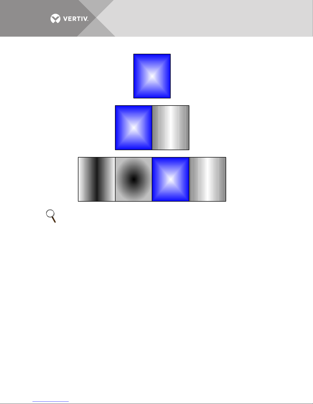
Figure 1 Cabinet arrangement—Liebert EXM UPS, battery cabinets, maintenance bypass cabinet
Liebert
EXM
UPS
Liebert
EXM
UPS
Maintenance
Bypass
Cabinet
(Matching)
Battery
Cabinet
(Matching)
Liebert
EXM
UPS
Maintenance
Bypass
Cabinet
(Matching)
Additional
Battery
Cabinet(s)
(Matching)
If a maintenance bypass
cabinet is used, it must be
installed on the right side of
the Liebert EXM UPS.
NOTE
The 200mm and 300mm maintenance bypass cabinets ship attached to the UPS.
The 600mm and 800mm maintenance bypass cabinets ship separately from the UPS.
Vertiv™|Liebert® EXM™ MBC Installation Manual | 8
Page 15
1.6.1 Power Cable Connection Procedure
The system input, UPS bypass, UPS output and system output cables (all require lug type
terminations) are connected to power blocks behind the power isolator switches as shown in
2.0 - Installation Drawings. These are accessible when the side or top panel is removed.
Equipment Ground
The equipment ground busbar is near the input and output power supply connections as shown
in 2.0 - Installation Drawings. The grounding conductor must be connected to the ground
busbar.
All cabinets and cable trunking should be grounded in accordance with local regulations.
WARNING
Risk of electric shock. Can cause equipment damage, injury and death.
Failure to follow adequate grounding procedures can result in electric shock hazard to
personnel and the risk of fire, should a ground fault occur.
AVERTISSEMENT
Risque de décharge électrique pouvant entraîner des dommages matériels, des blessures
et même la mort.
Le non-respect des procédures de mise à la terre peut entraîner des risques
d’électrocution du personnel, ou des risques d’incendie en cas de défectuosité de la mise à
la terre.
WARNING
Risk of electric shock. Can cause equipment damage, injury and death.
The operations described in this section must be performed by authorized electricians or
properly trained and qualified technical personnel wearing adequate safety clothing, eye
protection and gloves.
If you have any difficulties, do not hesitate to contact Vertiv. See the back page of this
manual for contact information.
AVERTISSEMENT
Risque de décharge électrique pouvant entraîner des dommages matériels, des blessures
et même la mort.
Toutes les opérations décrites dans cette section ne doivent être effectuées que par des
électriciens ou des techniciens professionnels dûment formés et qualifiés portant gants,
lunettes et vêtements de protection adéquats.
En cas de problème, n’hésitez pas à communiquer avec Vertiv. Pour obtenir les
renseignements de contact, consultez la dernière page de ce manuel.
NOTE
Proper grounding considerably reduces problems in systems caused by electromagnetic
interference.
Vertiv™|Liebert® EXM™ MBC Installation Manual | 9
Page 16
Once the equipment has been finally positioned and secured, connect the power cables as
described in the following procedure.
Refer to the appropriate cable connection drawing in 2.0 - Installation Drawings.
1. Verify that the bypass equipment is isolated from its external power source and all the power isolators are
open. Check that these supplies are electrically isolated and post any necessary warning signs to prevent
their inadvertent operation.
2. Remove the panels.
3. Connect the ground and any necessary main bonding jumper to the equipment ground busbar.
NOTE
The grounding and neutral bonding arrangement must be in accordance with local and national
codes of practice.
NOTE
Care must be taken when routing power cables. Ensure that the cables do not touch other
busbars.
4. Connect the AC input supply cables between the power distribution panel and the Maintenance Bypass
input supply busbars (A-B-C or A-B-C-N terminals) and tighten the connections to the proper torque (see
Ta bl e 2 1). Ensure correct phase rotation!
5. Connect the UPS Input
a. For two-breaker Liebert EXM MBC’s
1. If the system is a two-input type, connect the AC input supply cables between the Liebert EXM MBC
and the UPS bypass input supply busbars (A-B-C or A-B-C-N terminals) and between the power
distribution panel and the UPS rectifier input supply busbars (A-B-C or A-B-C-N terminals). Tighten the
connections to the proper torque. Ensure correct phase rotation!
2. If the system is a single-input type, connect the AC input supply cables between the Liebert EXM MBC
and the UPS bypass input supply busbars (A-B-C or A-B-C-N terminals) and connect AC jumper
connectors between UPS bypass input supply busbars and UPS rectifier input supply busbars (A-B-C
terminals). Tighten the connections to the proper torque (see Tab le 2 1). Ensure correct phase rotation!
6. Connect the system output power cables between the Liebert EXM MBC output (A-B-C or A-B-C-N
terminals) and the critical load and tighten the connections to the proper torque (see Tab le 2 1). Ensure
correct phase rotation!
7. Connect the control wiring from the Liebert EXM MBC terminal block TB1 to the Liebert EXM UPS Bypass
Module (X9 J23 and J26). Tighten the connections to the proper torque (see Ta bl e 2 1).
8. Replace the panels.
Table 1 Control wiring for Liebert EXM UPS to Liebert EXM MBC
From Liebert EXM
UPS Bypass Module
(X9 J23 and J26)
J26-15 TB1-6
J26-13 TB1-5
J26-11 TB1-4
J26-9 TB1-3
J23-3 TB1-9
J23-4 TB1-11
J23-6 TB1-12
To Liebert EXM MBC
Terminal Block (TB1)
Notes
Refer to the Liebert EXM UPS installation manual, SL-25648, SL-25650, or SL-26100, for
additional details about the Liebert EXM 10-40kVA, 60-100kVA, and 120-200kVA UPS's. The
manual is available at the Liebert Web site: www.liebert.com
Vertiv™|Liebert® EXM™ MBC Installation Manual | 10
Page 17

The following are guidelines only and are superseded by local regulations and codes of practice
where applicable.
• Take special care when determining the size of the neutral cable, because current circulating on the neutral
cable may be greater than nominal current in the case of non-linear loads.
• The ground conductor should be sized according to local or NEC codes, cable lengths, type of protection,
etc. The ground cable connecting the UPS to the main ground system must follow the most direct route
possible.
• Consideration should be given to the use of smaller, paralleled cables for heavy currents, as a way to ease
installation.
• In most installations, the load equipment is connected to a distribution network of individually protected
busbars fed by the Liebert EXM MBC output rather than being connected directly to the Liebert EXM MBC
itself. Where this is the case, the Liebert EXM MBC output cables can be rated to suit the individual
distribution network demands rather than being fully load-rated.
• When laying the power cables, do not form coils to avoid increasing formation of electromagnetic
interference.
Vertiv™|Liebert® EXM™ MBC Installation Manual | 11
Page 18
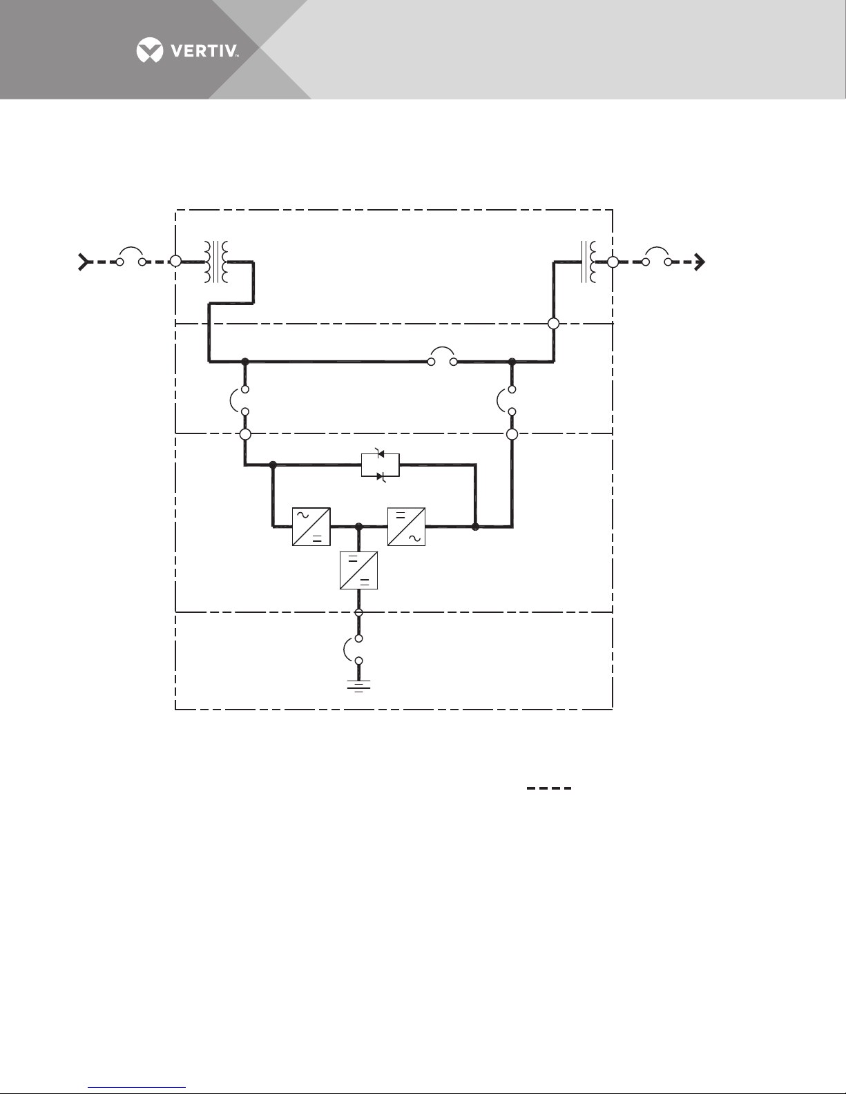
2.0 INSTALLATION DRAWINGS
MAINTENANCE BYPASS CABINET
MIB
BIB
MBB
* Rectifier
AC Input
480V
3 Wire + GND
AC Output
480/277V
4 Wire + GND
Static Bypass
See Note 6
UPS CABINET
DUAL TRANSFORMER CABINET
BATTERY
NOTES:
1. Install in accordance with national and local electrical codes.
2. Input and bypass must share the same single source.
3. Bypass and rectifier inputs and output cables must be
run in separate conduits.
4. Control wiring must be run in separate conduits.
5. Internal battery breaker is optional on UPS with internal batteries;
battery breaker is factory-supplied with external Liebert battery cabinets.
BIB - Bypass Isolation Breaker
MBB - Maintenance Bypass Breaker
MIB - Maintenance Isolation Breaker
* External Overcurrent Protection by Others
Field-Supplied Wiring
EXM11022
Rev. 1
Figure 2 One-line diagram, single-input Liebert EXM 10-40kVA UPS with three-breaker Liebert EXM MBC
and input/output transformer cabinet
Vertiv™|Liebert® EXM™ MBC Installation Manual | 12
Page 19
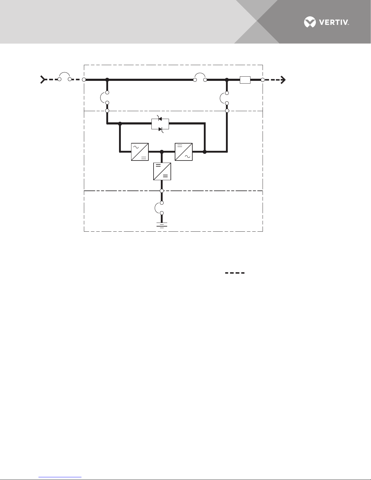
Figure 3 One-line diagram, single-input Liebert EXM 10-200kVA UPS with three-breaker Liebert EXM MBC
MAINTENANCE BYPASS CABINET
*Bypass
AC Input
4 Wire + GND
Static Bypass
UPS CABINET
BATTERY
NOTES:
1. Install in accordance with national and local electrical codes.
2. Input and bypass must share the same single source.
3. A neutral is required from the system AC input source.
Vertiv recommends a full capacity neutral conductor
and grounding conductors.
4. Bypass and rectifier inputs and output cables must be
run in separate conduits.
5. Control wiring must be run in separate conduits..
6. Internal battery breaker is optional on UPS with internal batteries;
battery breaker is factory-supplied with external Liebert battery cabinets.
MBB
Output
MIBBIB
Busbar
BIB - Bypass Isolation Breaker
MBB - Maintenance Bypass Breaker
MIB - Maintenance Isolation Breaker
* External Overcurrent Protection by Others
Field-Supplied Wiring
AC Output
208V
4 Wire + GND
EXM11011
Rev. 2
Vertiv™|Liebert® EXM™ MBC Installation Manual | 13
Page 20
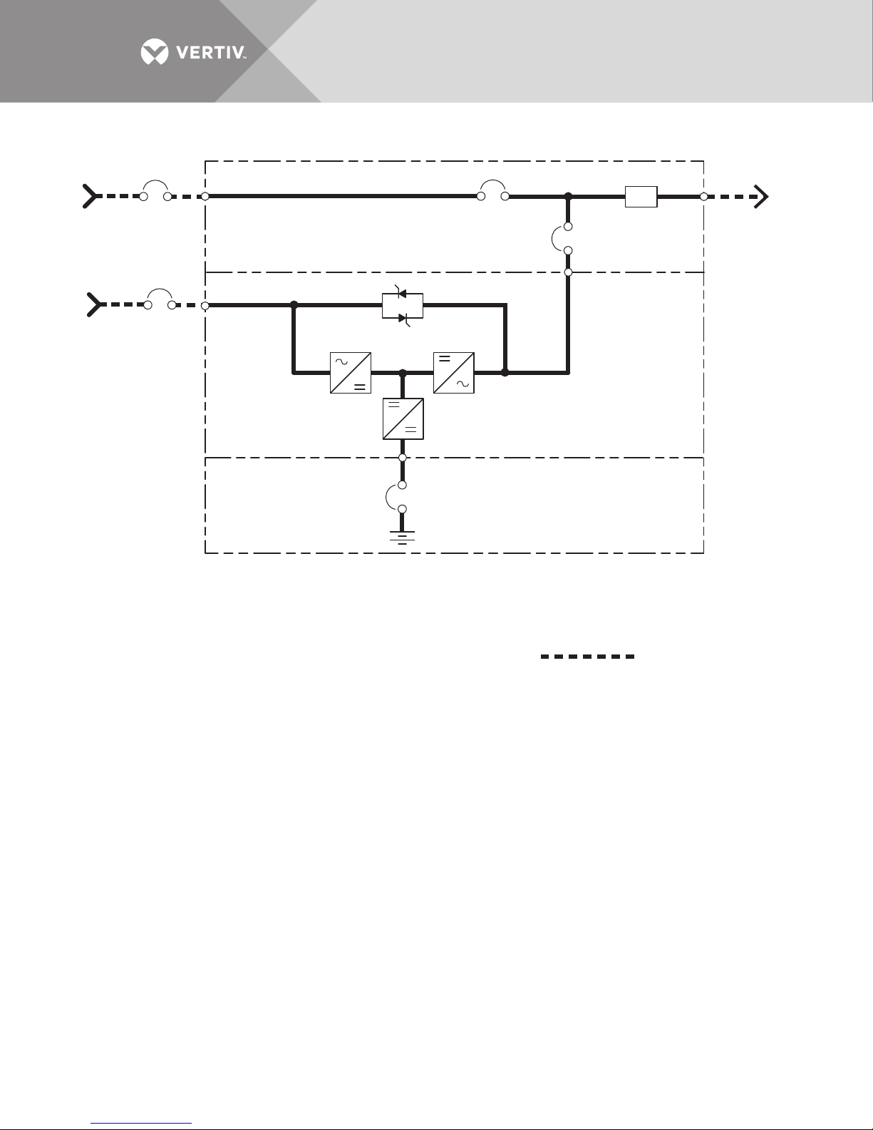
Figure 4 One-line diagram, dual-input Liebert EXM 10-100kVA with two-breaker Liebert MBC
MAINTENANCE BYPASS CABINET
*Bypass
AC Input
4 Wire + GND
See Note 6
*UPS
AC Input
4 Wire + GND
UPS CABINET
BATTERY
NOTES:
1. Install in accordance with national and local electrical codes.
2. Input and bypass must share the same single source.
3. A neutral is required from the system AC input source.
Vertiv recommends a full capacity neutral conductor
and grounding conductors.
4. Bypass and rectifier inputs and output cables must be
run in separate conduits.
5. Control wiring must be run in separate conduits.
6. Customer must supply shunt trips with 120V coils on
the bypass breaker and rectifier breaker.
Static Bypass
MBB
Output
MIB
BIB - Bypass Isolation Breaker
MBB - Maintenance Bypass Breaker
MIB - Maintenance Isolation Breaker
* External Overcurrent Protection by Others
Busbar
Field-Supplied Wiring
AC Output
208V or 220V
4 Wire + GND
Vertiv™|Liebert® EXM™ MBC Installation Manual | 14
Page 21
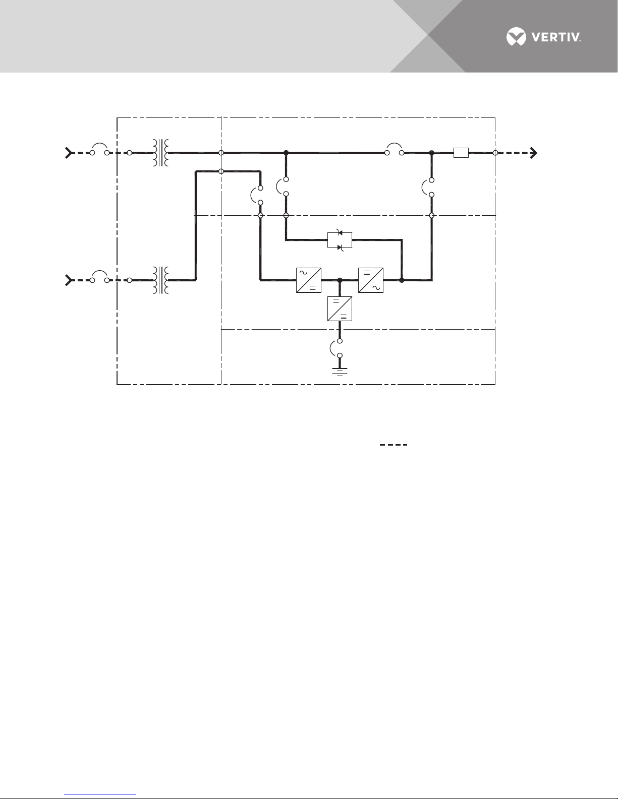
Figure 5 One-line diagram, dual-input Liebert EXM 10-100kVA UPS with four-breaker Liebert EXM MBC and
MAINTENANCE BYPASS CABINET
MIB
BIB
RIB
MBB
*Bypass
AC Input
3 Wire + GND
* Rectifier
AC Input
3 Wire + GND
AC Output
208V
4 Wire + GND
Static Bypass
UPS CABINET
DUAL
TRANSFORMER
CABINET
BATTERY
Output
Busbar
NOTES:
1. Install in accordance with national and local electrical codes.
2. Vertiv recommends a full capacity neutral conductor
and grounding conductors.
3. Bypass and rectifier inputs and output cables must be
run in separate conduits.
4. Control wiring must be run in separate conduits.
5. Transformer available: 208, 220, 480, 600V input.
6. Internal battery breaker is optional on UPS with internal batteries;
battery breaker is factory-supplied with external Liebert battery cabinets.
RIB - Rectifier Input Breaker
BIB - Bypass Isolation Breaker
MBB - Maintenance Bypass Breaker
MIB - Maintenance Isolation Breaker
* External Overcurrent Protection by Others
Field-Supplied Wiring
EXM11009
Rev. 2
See Note 6
See Note 5
See Note 5
input isolation transformer cabinet
Vertiv™|Liebert® EXM™ MBC Installation Manual | 15
Page 22
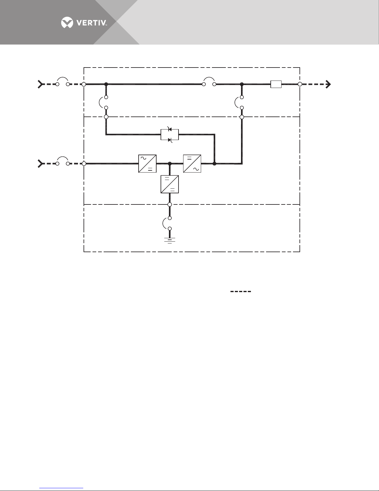
Figure 6 One-line diagram, dual-input Liebert EXM 10-200kVA UPS with three-breaker Liebert EXM MBC
MAINTENANCE BYPASS CABINET
MIB
BIB
MBB
Static Bypass
Output
Busbar
* Rectifier
AC Input
4 Wire + GND
See Note 6
* Bypass
AC Input
4 Wire + GND
AC Output
208V
4 Wire + GND
See Note 7
UPS CABINET
BATTERY
NOTES:
1. Install in accordance with national and local electrical codes.
2. Input and bypass must share the same single source.
3. A neutral is required from the system AC input source. Vertiv
recommends a full capacity neutral conductor and grounding conductors.
4. Bypass and rectifier inputs and output cables must be
run in separate conduits.
5. Control wiring must be run in separate conduits.
6. A shunt trip breaker with 120V coil is required.
7. Internal battery breaker is optional on UPS with internal batteries;
battery breaker is factory-supplied with external Liebert battery cabinets.
BIB - Bypass Isolation Breaker
MBB - Maintenance Bypass Breaker
MIB - Maintenance Isolation Breaker
* External Overcurrent Protection
by Others
EXM11013
Rev. 3
Field-Supplied Wiring
Vertiv™|Liebert® EXM™ MBC Installation Manual | 16
Page 23
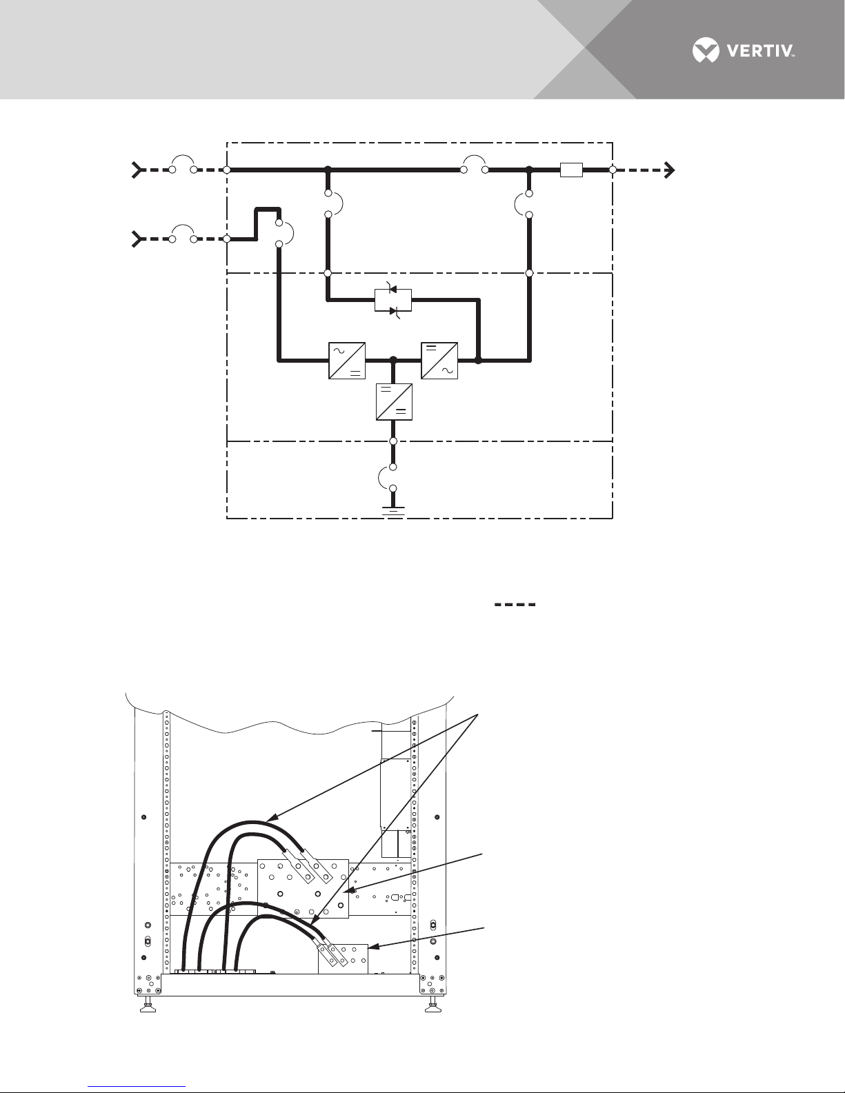
Figure 7 One-line diagram, dual input Liebert EXM 10-200kVA with four-breaker Liebert MBC
MAINTENANCE BYPASS CABINET
*Bypass
AC Input
4 Wire + GND
RIB
*Rectifier
AC Input
4 Wire + GND
UPS CABINET
BATTERY
NOTES:
1. Install in accordance with national and local electrical codes.
2. Input and bypass must share the same single source.
3. A neutral is required from the system AC input source.
Vertiv recommends a full capacity neutral conductor
and grounding conductors.
4. Bypass and rectifier inputs and output cables must be
run in separate conduits.
5. Control wiring must be run in separate conduits.
6. Internal battery breaker is optional on UPS with internal batteries;
battery breaker is factory-supplied with external Liebert battery cabinets.
BIB
Static Bypass
MBB
MIB
RIB - Rectifier Input Breaker
BIB - Bypass Isolation Breaker
MBB - Maintenance Bypass Breaker
MIB - Maintenance Isolation Breaker
* External Overcurrent Protection by Others
Output
Busbar
Field-Supplied Wiring
EXM11014
Rev. 2
AC Output
4 Wire + GND
Figure 8 Bend radius—Neutral and ground wires through bottom feed, 10-40kVA system
208V
Vertiv™|Liebert® EXM™ MBC Installation Manual | 17
When attaching neutral and ground wires
from the bottom feed, connection must
be made to the top of the neutral and
ground busbar for required bend radius.
Neutral Busbar
Ground Busbar
Page 24
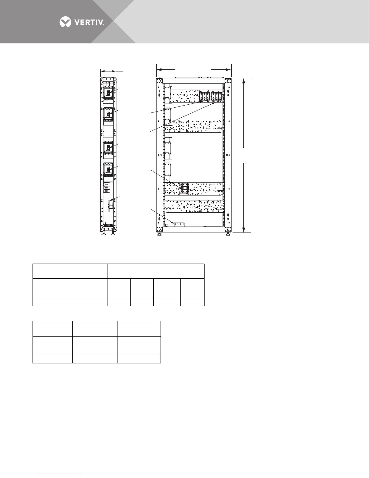
Figure 9 Main components—200mm Liebert EXM MBC, two to four breakers, 10-40kVA system
RIB
BIB
MBB
MIB
Neutral
Busbar
FRONT
Door Not Shown
7.9"
(200mm)
Ground
Busbar
TB4
(Dual
Input)
TB2
TB3
37.5" (953mm)
RIGHT SIDE
Panel Not Shown
78.8"
(2001mm)
EXM12006
Pg. 2, Rev. 5
Table 2 Breaker configuration—200mm Liebert EXM MBC two to four breakers, 10-40kVA system
Liebert EXM MBC Breaker
Configuration Configured Breaker
2——MBBMIB
3 — BIB MBB MIB
4 RIB BIB MBB MIB
Table 3 Terminal block details—200mm Liebert EXM MBC, two to four breakers, 10-40kVA system
Terminal
Block
TB2 Input Bypass
TB3 Output Output
TB4 — Rectifier
Single Input
System
Dual Input
System
Vertiv™|Liebert® EXM™ MBC Installation Manual | 18
Page 25
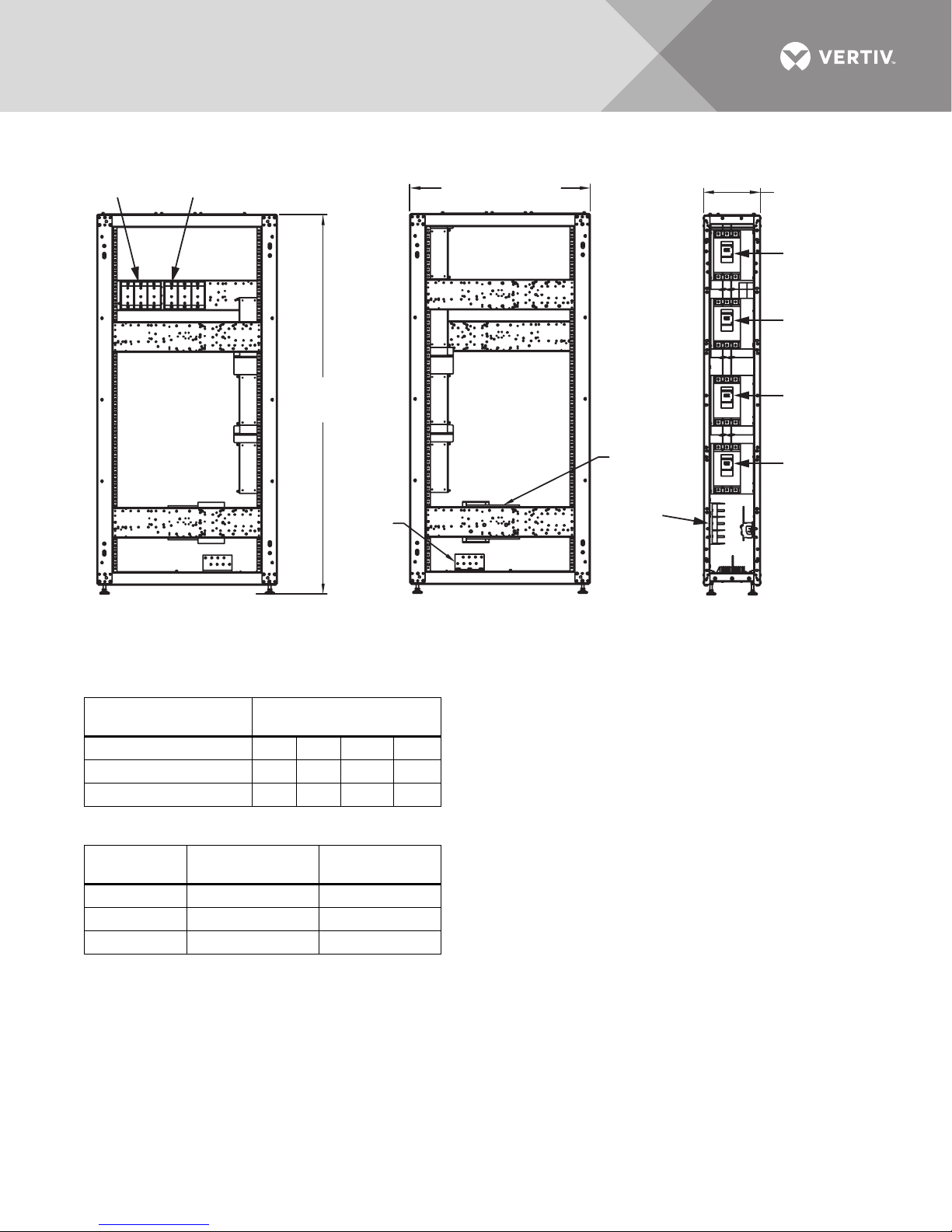
Figure 10 Main components—300mm Liebert EXM MBC, two to four breakers, 60-100kVA system
11.8"
(300mm)
37.5" (953mm)
78.5"
(1994mm)
MIB
EXM15003
Rev. 0
TB2
TB3
MBB
BIB
RIB
FRONT
Door Removed
LEFT SIDE
Panel Removed
RIGHT SIDE
Panel Removed
Ground
Busbar
Neutral
Busbar
TB4 -Dual Input Systems
Table 4 Breaker configuration, 300mm Liebert EXM MBC, two to four breakers, 60-100kVA system
Liebert EXM MBC
Breaker Configuration Configured Breaker
Table 5 Terminal block details—300mm Liebert EXM MBC, two to four breakers, 60-100kVA system
Ter m in al
Block
2——MBBMIB
3 — BIB MBB MIB
4 RIB BIB MBB MIB
Single Input
System
TB2 Input Bypass
TB3 Output Output
TB4 — Rectifier
Dual Input
System
Vertiv™|Liebert® EXM™ MBC Installation Manual | 19
Page 26
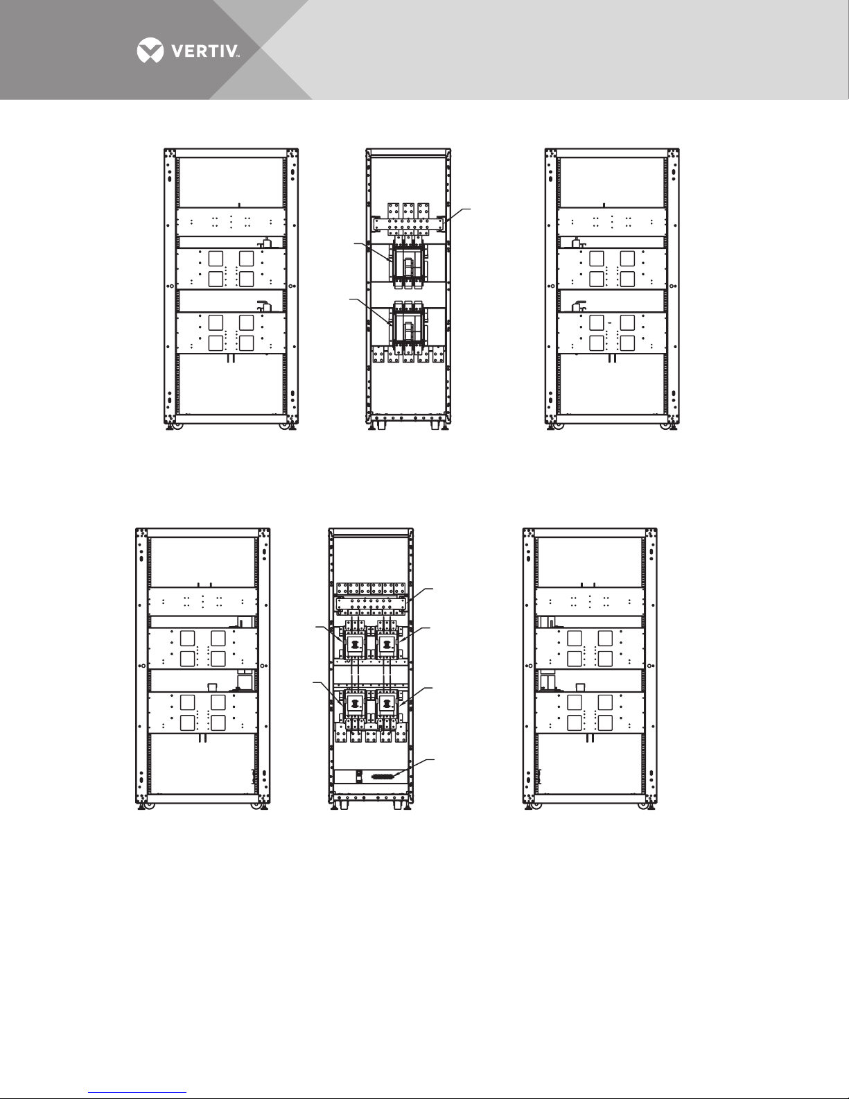
Figure 11 Main components—600mm Liebert EXM MBC, two breakers, 120-200kVA system
RIGHT SIDE VIEW
Panel Removed
LEFT SIDE VIEW
Panel Removed
FRONT VIEW
Door Removed
Neutral
Busbar
MBB
MIB
EXM15104
RIGHT SIDE VIEW
Panel Removed
LEFT SIDE VIEW
Panel Removed
FRONT VIEW
Door Removed
Neutral
Busbar
Terminal
Strip
RIB
BIB
MIB
MBB
EXM15103
Figure 12 Main components—600mm Liebert EXM MBC, three to four breakers, 120-160kVA system
Vertiv™|Liebert® EXM™ MBC Installation Manual | 20
Page 27
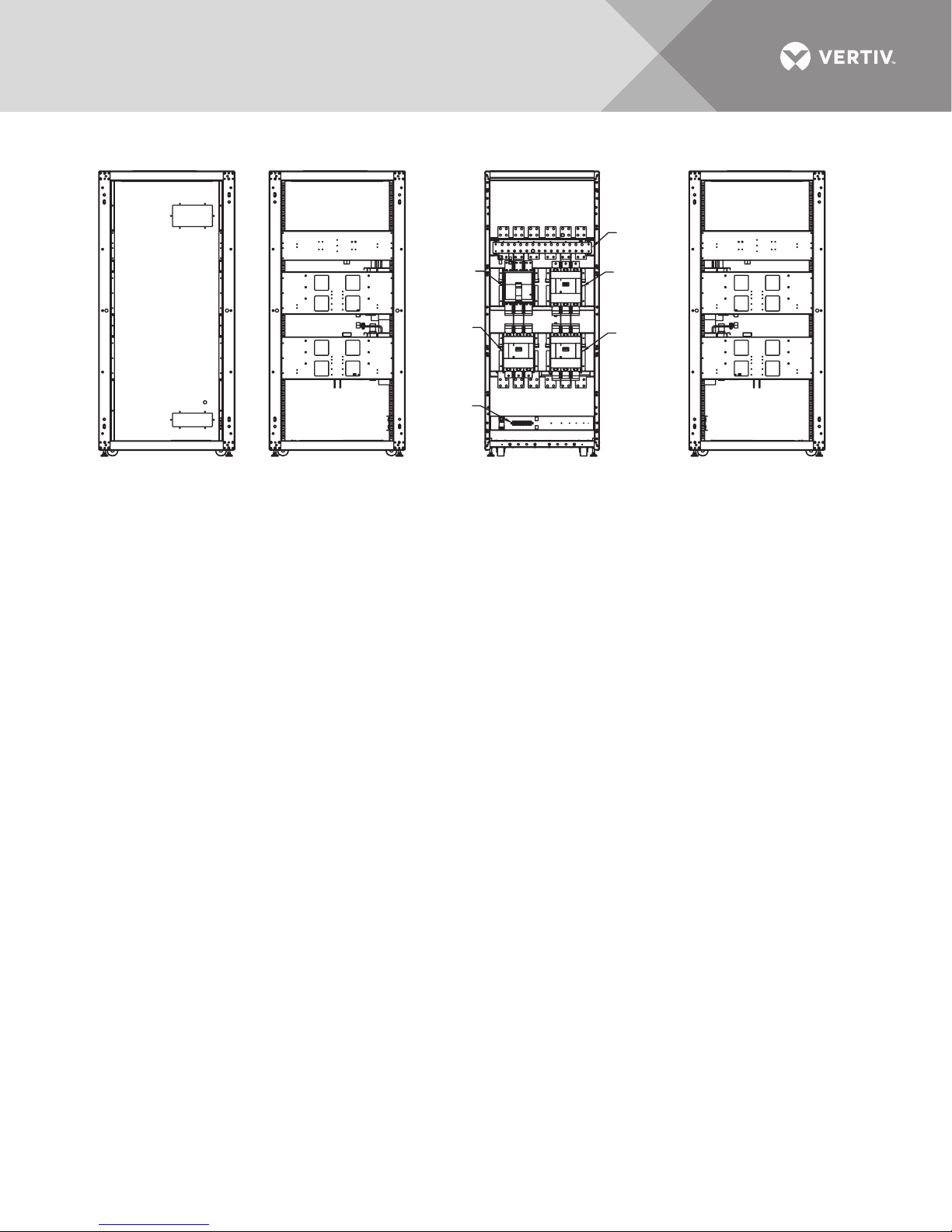
Figure 13 Main components—800mm Liebert EXM MBC, three or four breakers, 160-200kVA system
RIGHT SIDE VIEW
Panel Removed
LEFT SIDE VIEW
with Panel Removed
(160/180kVA Models)
LEFT SIDE VIEW
Panel Removed
(200kVA Model Only)
FRONT VIEW
Door Removed
Neutral
Busbar
Terminal
Strip
RIB
MBB
BIB
MIB
EXM15105
Rev. 0
Vertiv™|Liebert® EXM™ MBC Installation Manual | 21
Page 28
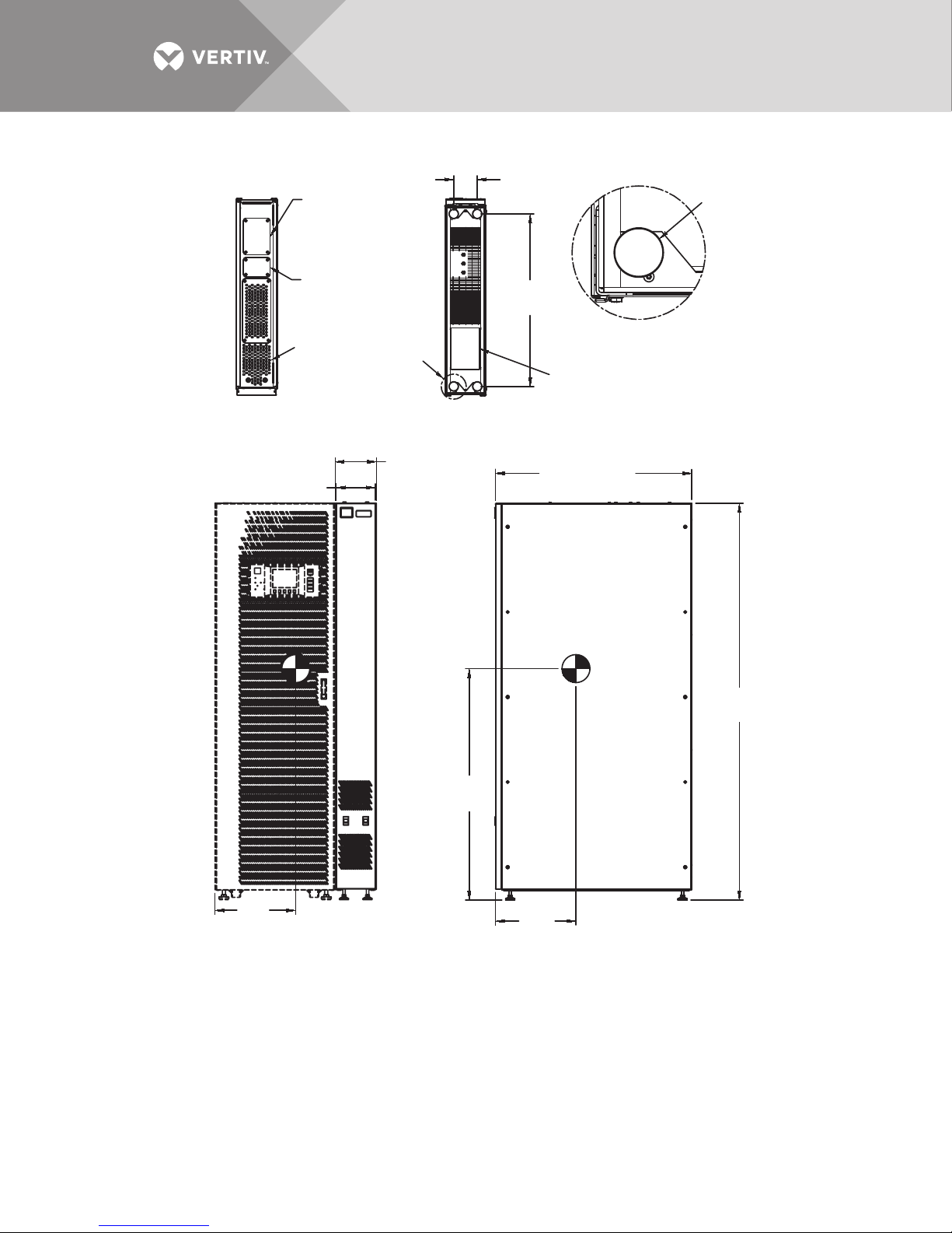
Figure 14 Outline drawing—200mm Liebert EXM MBC, two to four breakers, 10-40kVA system
NOTES
1. 24" (610) minimum clearance above unit for air exhaust and
36" (914) front access required for service.
2. Keep cabinet within 15 degrees of vertical.
3. Top and bottom cable entry available through removable access plates.
Remove, punch to suit conduit size and replace.
4. Unit bottom is structurally adequate for forklift handling.
5. Control wiring and power wring must be run in separate conduits.
6. All wiring must be in accordance with national and local electrical codes.
7. Liebert EXM MBC will always be attached to the UPS; UPS shown for reference only.
8. Overall dimensions are shown with side panels.
Leveler
DETAIL A
TOP
BOTTOM
FRONT
UPS Shown for Reference Only
RIGHT SIDE
EXM12006
Pg. 1, Rev. 5
39.1" (993mm)
7.8" (200mm)
8.2"
(208mm)
Overall
78.7"
(2000mm)
See
Detail A
34.3"
(872mm)
4.7"
(119mm)
Ventilation
Control Cable
Entry 5.3" x 3.9"
(135 x 99mm)
Power Cable
Entry 5.3" x 7.3"
(135 x 185mm)
Power Cable
Entry 5.7" x 8.3"
(145 x 211mm)
16.1"
(408mm)
46"
(1168mm)
16.1"
(406mm)
Vertiv™|Liebert® EXM™ MBC Installation Manual | 22
Page 29
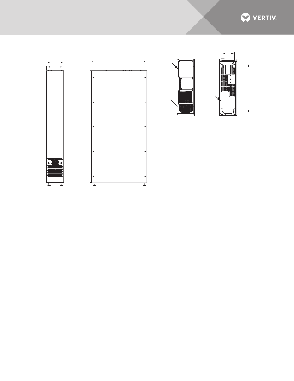
Figure 15 Outline drawing—300mm Liebert EXM MBC, two to four breakers, 60-100kVA system
NOTES:
1. All dimensions are in inches (mm).
2. 24" (610) minimum clearance above unit and
36" (914) front access required for service.
3. Keep cabinet within 15 degrees of vertical.
4. Top and bottom cable entry available through
removable access plates. Remove, punch to suit
conduit size and replace.
5. Unit bottom is structurally adequate for forklift handling.
6. Control wiring and power wiring must be run in
separate conduits.
7. All wiring is to be in accordance with national
and local electrical codes.
TOP BOTTOM
EXM12007
Rev. 0
FRONT VIEW RIGHT SIDE VIEW
Ventilation
39.1" (993mm)
34.3"
(872mm)
8.6"
(218mm)
12.1"
(308mm)
11.8"
(300mm)
Conduit
Landing
Conduit
Landing
Vertiv™|Liebert® EXM™ MBC Installation Manual | 23
Page 30
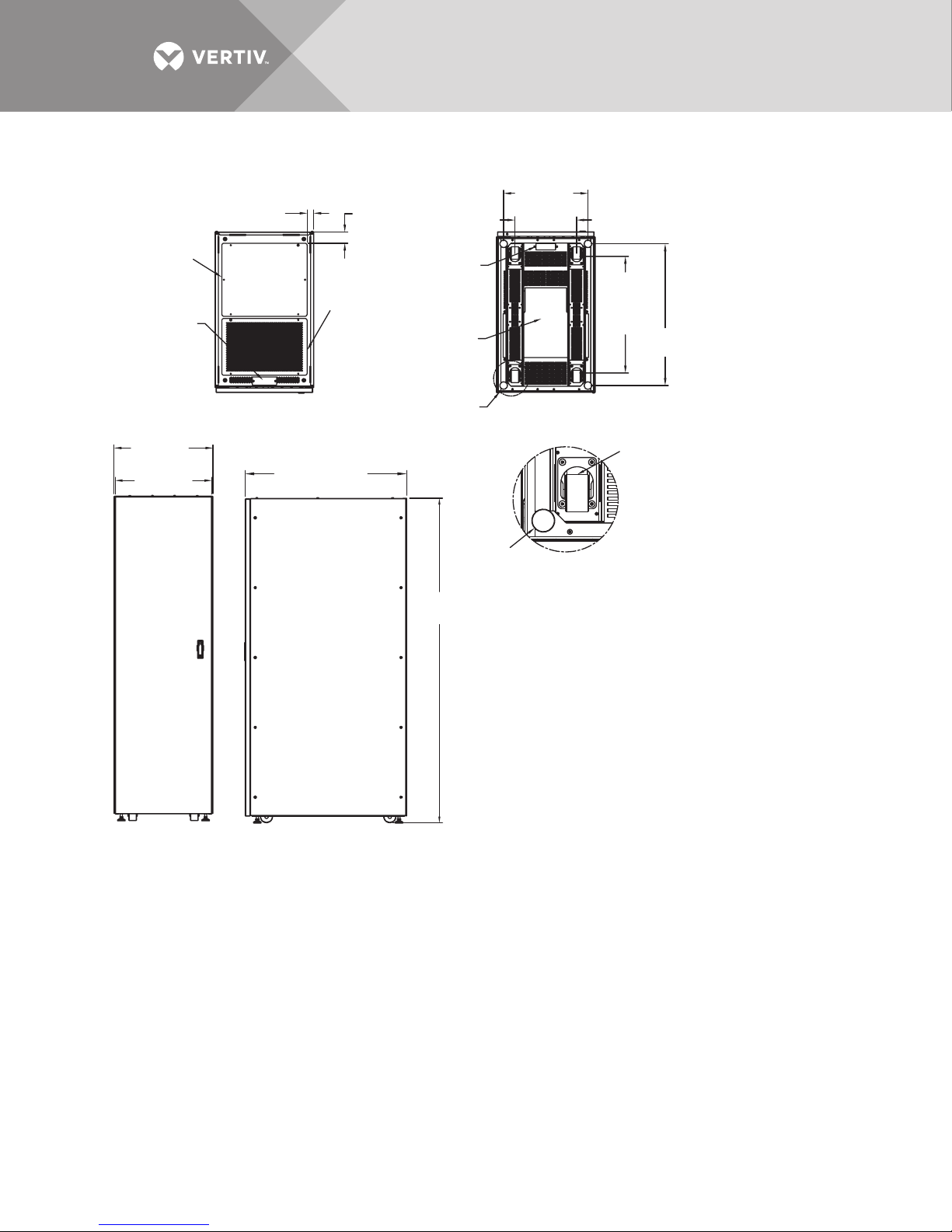
Figure 16 Outline drawing—600mm Liebert EXM MBC 120-200kVA system
Notes:
1. 24" (610mm) minimum clearance above unit for air exhaust.
36" (914mm) front access required for service.
2. Keep cabinet within 15 degrees of vertical.
3. Top and bottom cable entry available through removable access
plates. Remove, punch to suit conduit size and replace.
4. Unit bottom is structurally adequate for forklift handling.
5. Control wiring must be run in separate conduits.
6. All wiring is to be in accordance with national and local electrical codes.
7. The maintenance bypass cabinet will always be attached to the UPS.
Leveler
Caster
DETAIL A
FRONT VIEW
TOP VIEW
BOTTOM VIEW
39.1" (993mm)
23.9"
(608mm)
23.6"
(600mm)
78.7"
(2000mm)
Power Cable Entry
20.7" x 17.7"
(526mm x 450mm)
EXM12014
Rev. 1
RIGHT SIDE VIEW
Control Cable Entry
5.9" x 2.0"
(150mm x 51mm)
Control Cable Entry
4.7" (119mm) x
1.6" (41mm)
Power Cable Entry
10.6" (269mm) x
16.9" (429mm)
1.6"
(41mm)
2.7"
(69mm)
20.4"
(518mm)
15.0"
(381mm)
Ventilation
34.3"
(872mm)
28.3"
(719mm)
Breakout
Centers
See DETAIL A
Vertiv™|Liebert® EXM™ MBC Installation Manual | 24
Page 31
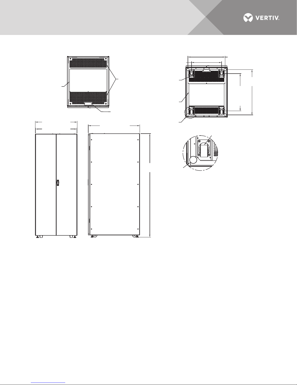
Figure 17 Outline drawing—800mm Liebert EXM MBC 160-200kVA system
Notes:
1. 24" (610mm) minimum clearance above unit for
air exhaust.
36" (914mm) front access required for service.
2. Keep cabinet within 15 degrees of vertical.
3. Top and bottom cable entry available through removable
access plates. Remove, punch to suit conduit size and replace.
4. Unit bottom is structurally adequate for forklift handling.
5. Control wiring must be run in separate conduits.
6. All wiring is to be in accordance with national and local
electrical codes.
7. The maintenance bypass cabinet will always be attached
to the UPS.
Leveler
Caster
DETAIL A
RIGHT SIDEFRONT
78.7"
(2000mm)
34.3"
(872mm)
39.1" (993mm)
31.8" (808mm)
31.3" (800mm)
28.3"
(719mm)
Breakout
Centers
28.3"
(719mm)
22.8" (579mm)
Control Cable Entry
4.7" x 1.6"
(119mm x 41mm)
Control Cable Entry
5.9" x 2.0"
(150mm x 51mm)
BOTTOM VIEW
TOP
Ventilation
See DETAIL A
Power Cable Entry
26.8" x 16.8"
(681mm x 427mm)
Power Cable Entry
28.3" x 17.5"
(719mm x 445mm)
EXM12015
Rev. 1
Vertiv™|Liebert® EXM™ MBC Installation Manual | 25
Page 32
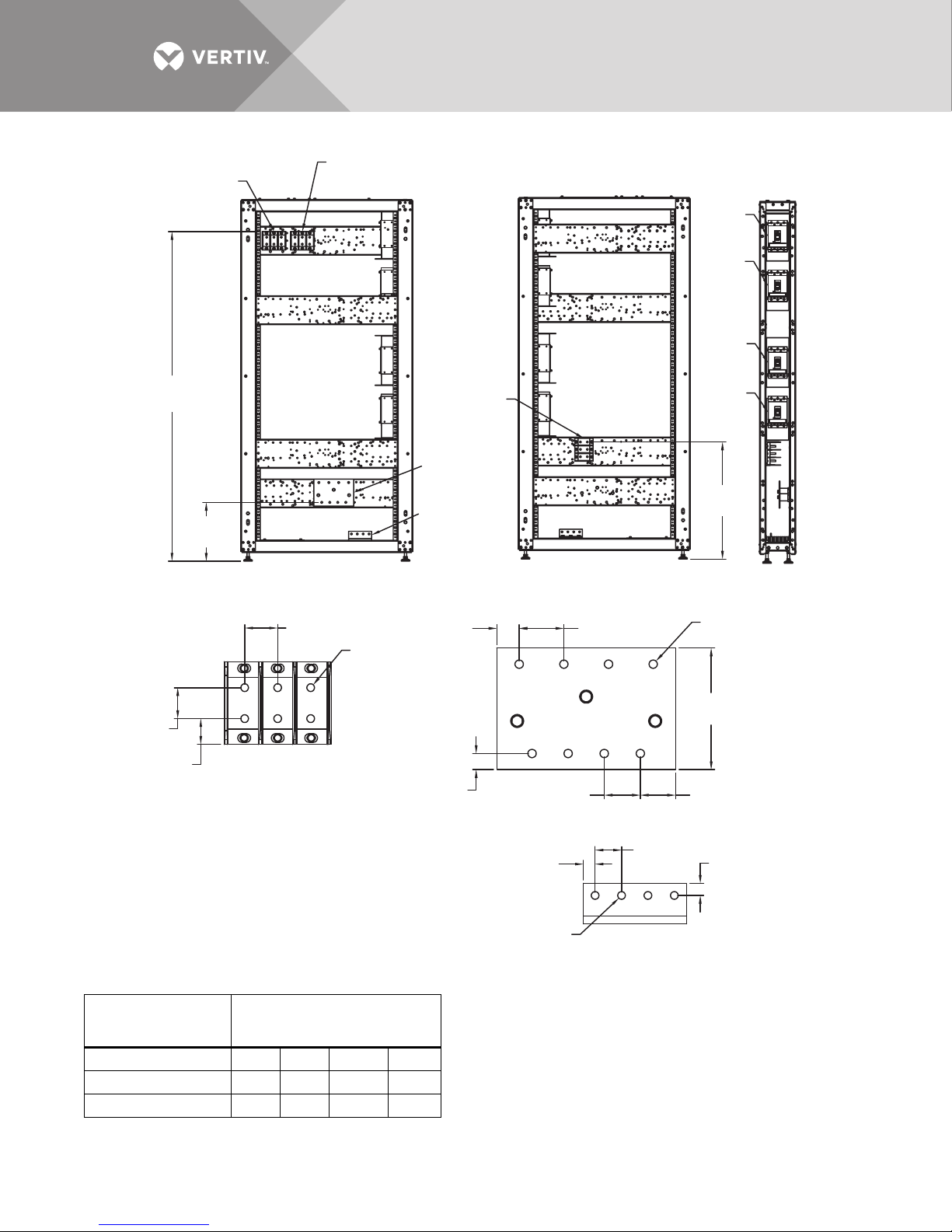
Figure 18 Terminal details—200mm Liebert EXM MBC, two to four breakers, 10-40kVA system
Input (TB2)
See Detail A
Rectifier Input (TB4)
See Detail A
RIB
BIB
MBB
71.9"
(1826mm)
12.8"
(325mm)
LEFT SIDE
Panel Not Shown
1.6" (41mm)
Ø0.38"
(9.6mm)
6 Typical
1.5"
(38mm)
1.25"
(32mm)
DETAIL A
TB2, TB3, TB4
NOTES:
1. Control wiring and power wiring must
be run in separate conduits.
2. All wiring must be in accordance with national
and local electrical codes.
3. If the maintenance bypass cabinet is attached
to the UPS, Vertiv will supply the interconnection
cables.
Output (TB3)
See Detail A
Neutral
Busbar
Ground
Busbar
1.1"
(28mm)
0.78"
(20mm)
RIGHT SIDE
Panel Not Shown
1.75" (44mm)
NEUTRAL BUSBAR
0.98"
(25mm)
Ø 0.38"
(9.6mm)
4 Typically
2.2"
(56mm)
(102mm)
1.3" (33mm)
Typical
GROUND BUSBAR
MIB
25.5"
(648mm)
FRONT
Door Not Shown
Ø 0.41" (10.4mm)
8 Typically
4"
1.7"
(43mm)
0.59" (15mm)
EXM16008
Rev. 2
Table 6 Breaker configuration—200mm Liebert EXM MBC, two to four breakers, 10-40kVA system
Liebert EXM MBC
Breaker
Configuration Configured Breaker
2——MBBMIB
3 — BIB MBB MIB
4 RIB BIB MBB MIB
Vertiv™|Liebert® EXM™ MBC Installation Manual | 26
Page 33
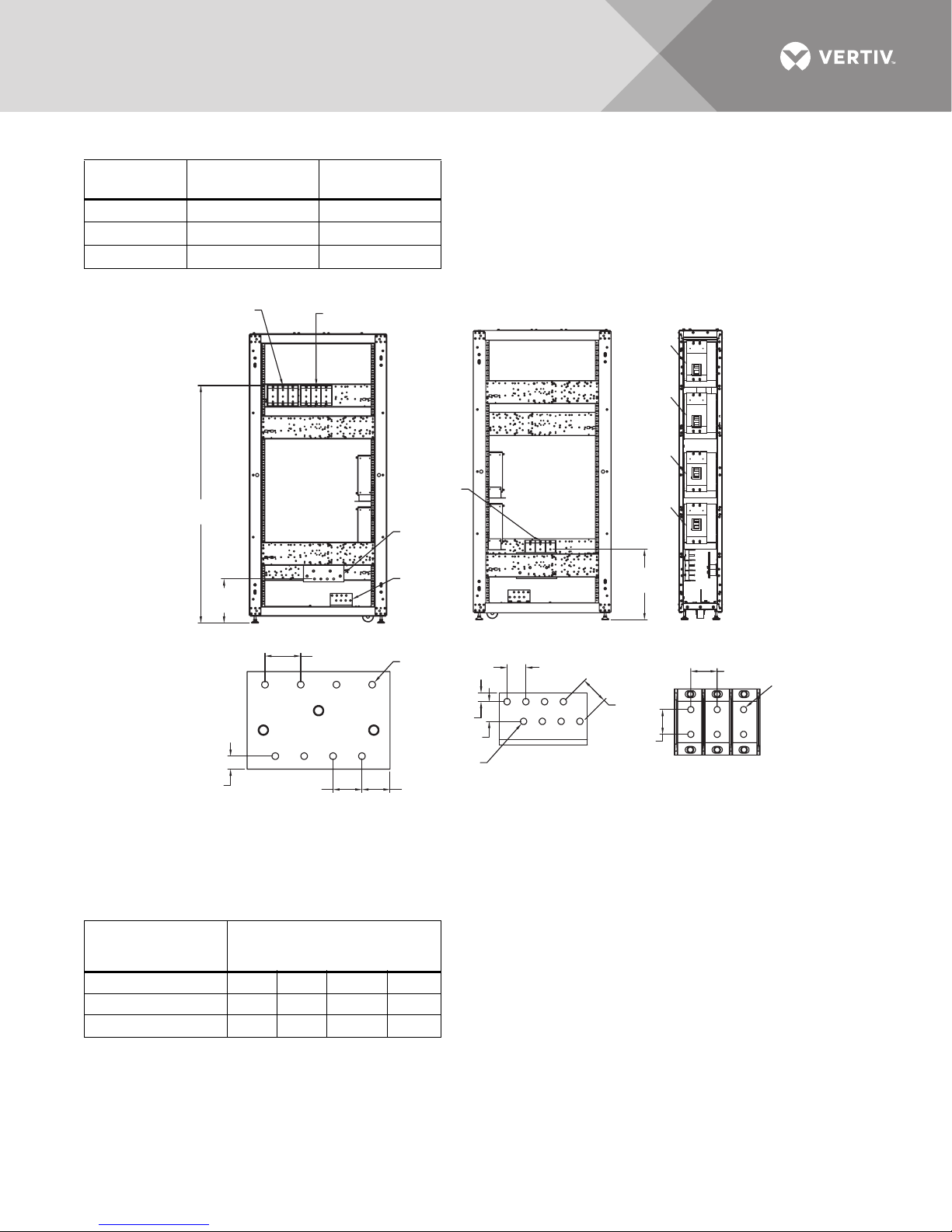
Table 7 Terminal block details—200mm Liebert EXM MBC, two to four breakers, 10-40kVA system
Ter m in al
Block
TB2 Input Bypass
TB3 Output Output
TB4 — Rectifier
Single Input
System
Dual Input
System
Figure 19 Terminal details—300mm Liebert EXM MBC, two to four breakers, 60-100kVA system
Input (TB2)
See Detail A
64.8"
(1646mm)
Rectifier Input (TB4)
See Detail A
Output (TB3)
See Detail A
RIB
BIB
MBB
MIB
Neutral
Busbar
Ground
12"
(305mm)
LEFT SIDE
Panel Not Shown
0.78"
(20mm)
NOTES
1. Control wiring and power wiring must be run in separate conduits.
2. All wiring must be in accordance with national and local electrical codes.
3. If the maintenance bypass cabinet is attached
to the UPS, Vertiv will supply the interconnection cables.
1.75" (44mm)
2.2"
(56mm)
NEUTRAL BUSBAR
Busbar
Ø 0.41" (10.4mm)
8 Typically
0.59" (15mm)
1.3" (33mm)
Ø 0.44"
(11mm)
8 Typically
RIGHT SIDE
Panel Not Shown
GROUND BUSBAR
EXM16011
Rev. 2
1.3" (33mm)
Typical
19.2"
(488mm)
1.75"
(44mm)
1.5"
(38mm)
FRONT
Door Not Shown
1.6" (41mm)
Ø0.38"
(9.6mm)
6 Typical
DETAIL A
Table 8 Breaker configuration—300mm Liebert EXM MBC, two to four breakers, 60-100kVA system
Liebert EXM MBC
Breaker
Configuration Configured Breaker
2——MBBMIB
3 — BIB MBB MIB
4 RIB BIB MBB MIB
Vertiv™|Liebert® EXM™ MBC Installation Manual | 27
Page 34
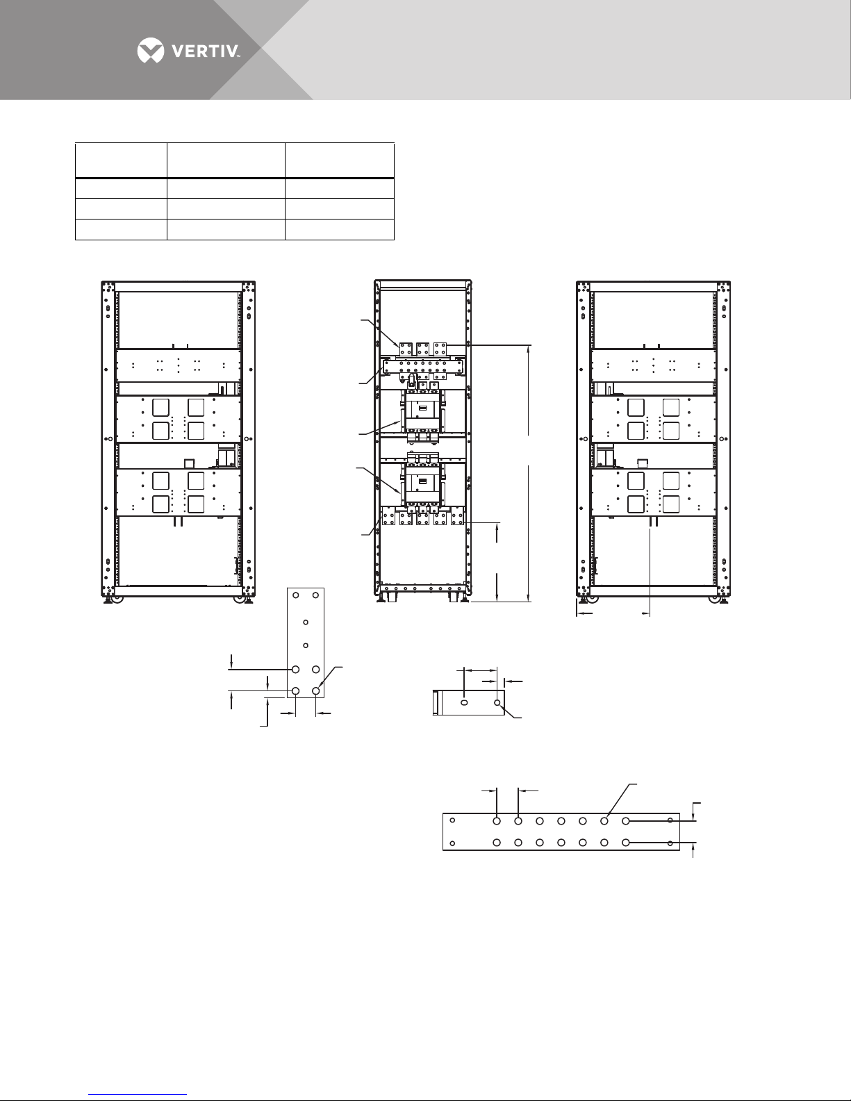
Table 9 Terminal block details—300mm Liebert EXM MBC, two to four breakers, 60-100kVA system
Ter m in al
Block
TB2 Input Bypass
TB3 Output Output
TB4 — Rectifier
Single Input
System
Dual Input
System
Figure 20 Terminal details—600mm Liebert EXM MBC, two breakers, 120-200kVA system
MBB Input
See Detail A
Neutral
Busbar
MBB
See Detail B
MIB
See Detail B
Ground Busbar
See Detail A
(493mm)
62.7"
(1593mm)
19.4"
LEFT SIDE
Panel Not Shown
Ø 0.56"
1.75" (44mm)
0.55"
(14mm)
NOTES
1. Control wiring and power wiring must
be run in separate conduits.
2. All wiring must be in accordance with national
and local electrical codes.
3. If the maintenance bypass cabinet is attached
to the UPS, Vertiv will supply the interconnection cables.
DETAIL A
(14mm)
1.7"
(43mm)
FRONT
Door Not Shown
(69mm)
Phase Busbar Connections
2.7"
DETAIL B
(455mm)
0.59"
(15mm)
Ø 0.44"
(11mm)
1.75"
(44mm)
Typical
NEUTRAL BUSBAR
17.9"
RIGHT SIDE
Panel Not Shown
Ø 0.56"
(14mm)
EXM16103
Rev. 2
1.75"
(44mm)
Vertiv™|Liebert® EXM™ MBC Installation Manual | 28
Page 35
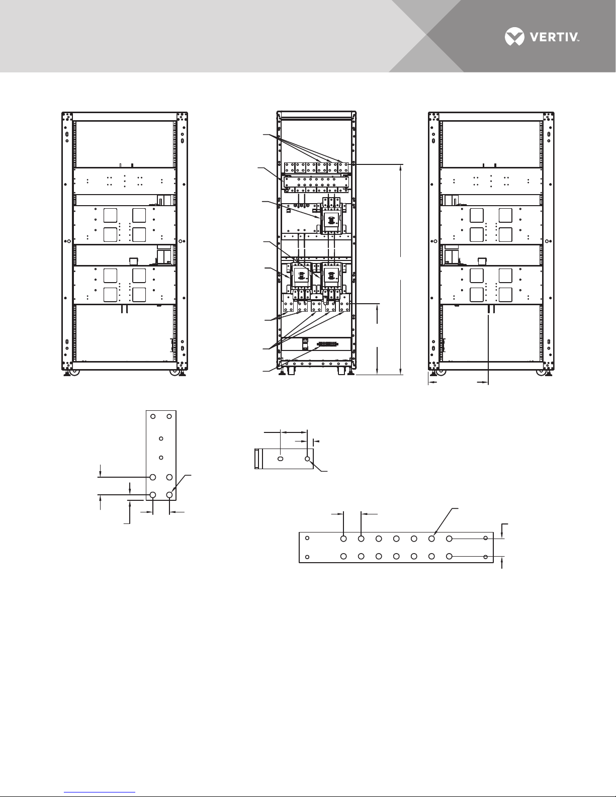
Figure 21 Terminal details—600mm Liebert EXM MBC, three breakers, 120-160kVA system
Bypass Input
Busbar
See Detail A
Neutral
Busbar
BIB
See Detail B
MBB
See Detail B
MIB
See Detail B
62.7"
(1593mm)
Ground Busbar
See Detail A
Output Busbar
21.1"
(536mm)
See Detail A
TB1
LEFT SIDE
Panel Not Shown
FRONT
Door Not Shown
2.7"
(69mm)
Ø 0.56"
1.75" (44mm)
(14mm)
DETAIL B
Phase Busbar Connections
0.55"
(14mm)
DETAIL A
NOTES
1. Control wiring and power wiring must
be run in separate conduits.
2. All wiring must be in accordance with national
and local electrical codes.
3. If the maintenance bypass cabinet is attached to the UPS,
Vertiv will supply the interconnection cables.
0.59"
(15mm)
Ø 0.44"
(11mm)
EXM16104
Rev. 2
1.75"
(44mm)
Typical
NEUTRAL BUSBAR
17.9"
(455mm)
Ø 0.56"
(14mm)
RIGHT SIDE
Panel Not Shown
1.75"
(44mm)
Vertiv™|Liebert® EXM™ MBC Installation Manual | 29
Page 36
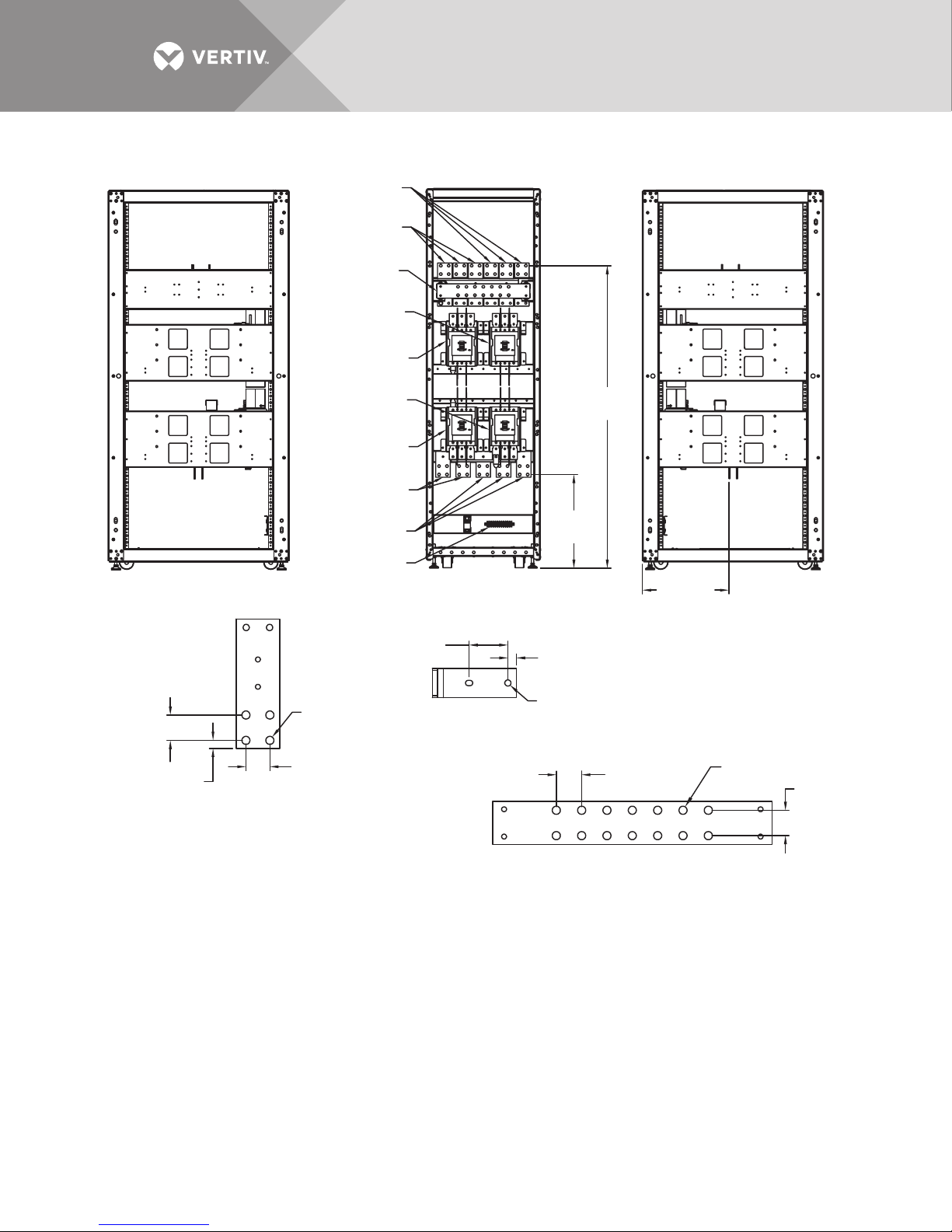
Figure 22 Terminal details—600mm Liebert EXM MBC, four breakers, 120-160kVA system
Bypass Input
See Detail A
Bypass Input
See Detail A
Neutral
Busbar
BIB
See Detail B
RIB
See Detail B
62.7"
(1593mm)
19.4"
(493mm)
17.9"
(455mm)
RIGHT SIDE
Panel Not Shown
0.59"
(15mm)
LEFT SIDE
Panel Not Shown
MBB
See Detail B
MIB
See Detail B
Ground Busbar
See Detail A
Output Busbar
See Detail A
TB1
FRONT
Door Not Shown
2.7"
(69mm)
Ø 0.56"
1.75" (44mm)
0.55"
(14mm)
NOTES
1. Control wiring and power wiring must
be run in separate conduits.
2. All wiring must be in accordance with national
and local electrical codes.
3. If the maintenance bypass cabinet is attached to the UPS,
Vertiv will supply the interconnection cables.
DETAIL A
(14mm)
1.7"
(43mm)
Phase Busbar Connections
DETAIL B
Ø 0.44"
(11mm)
1.75"
(44mm)
Typical
NEUTRAL BUSBAR
EXM16105
Rev. 2
Ø 0.56"
(14mm)
1.75"
(44mm)
Vertiv™|Liebert® EXM™ MBC Installation Manual | 30
Page 37
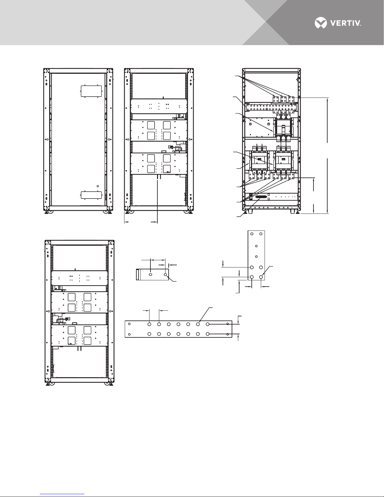
Figure 23 Terminal details—800mm Liebert EXM MBC, three breakers, 160-200kVA system
LEFT SIDE
Panel Not Shown
160-180kVA Model
LEFT SIDE
Panel Not Shown
200kVA Model
FRONT
Door Not Shown
RIGHT SIDE
Panel Not Shown
MIB
See Detail B
BIB
See Detail B
Bypass Input
Busbar
See Detail A
Output Busbar
See Detail A
Ground Busbar
See Detail A
Neutral
Busbar
MBB
See Detail B
NOTES
1. Control wiring and power wiring must
be run in separate conduits.
2. All wiring must be in accordance with national
and local electrical codes.
3. If the maintenance bypass cabinet is attached to the UPS,
Vertiv will supply the interconnection cables.
1.75"
(44mm)
Typical
1.75"
(44mm)
1.75" (44mm)
0.55"
(14mm)
1.7"
(43mm)
EXM16107
Rev. 2
2.7"
(69mm)
Ø 0.56"
(14mm)
19.4"
(493mm)
17.9"
(455mm)
NEUTRAL BUSBAR
DETAIL A
DETAIL B
Phase Busbar Connections
TB1
0.59"
(15mm)
Ø 0.44"
(11mm)
Ø 0.56"
(14mm)
62.7"
(1593mm)
Vertiv™|Liebert® EXM™ MBC Installation Manual | 31
Page 38
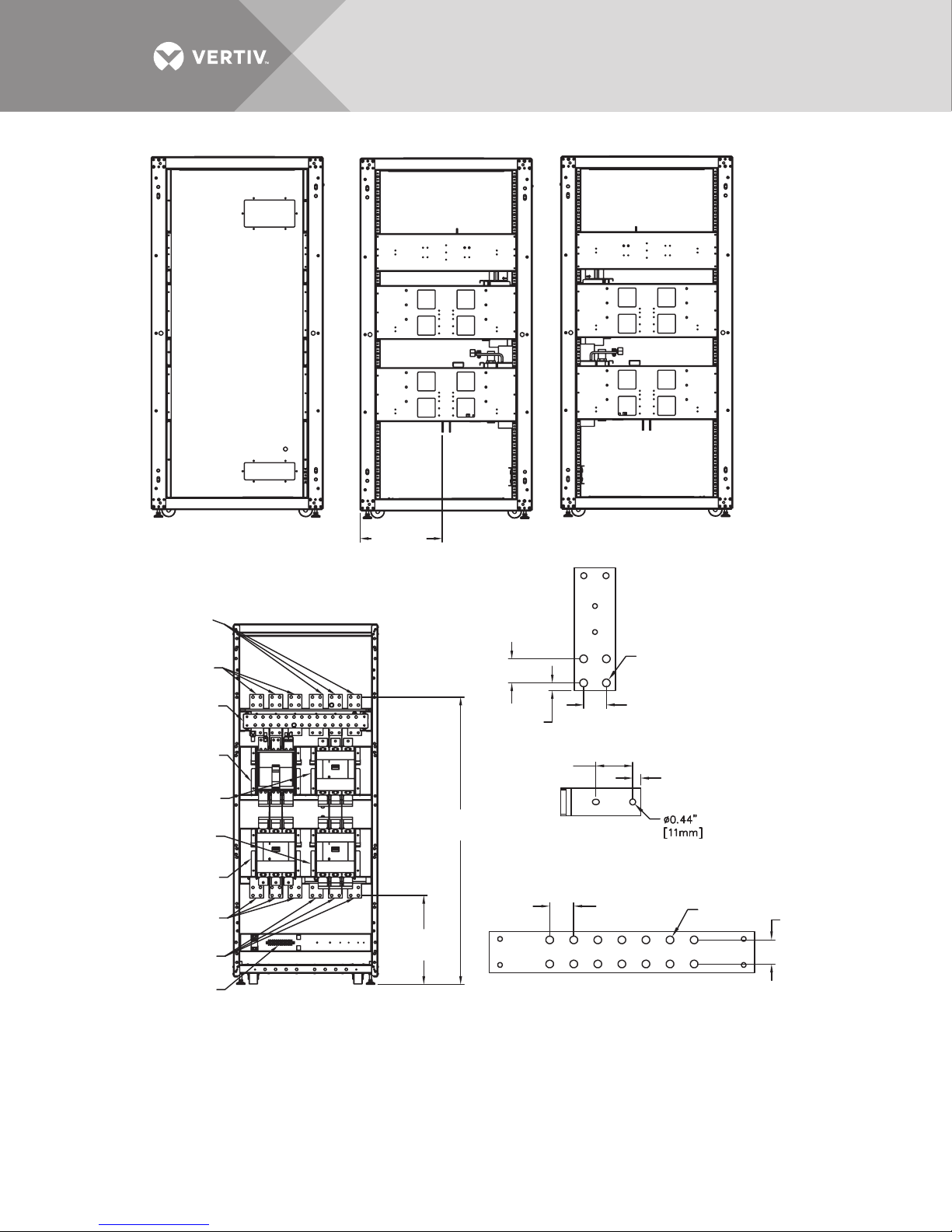
Figure 24 Terminal details—800mm Liebert EXM MBC, four breakers, 160-200kVA system
LEFT SIDE
Panel Not Shown
160-180kVA Model
LEFT SIDE
Panel Not Shown
200kVA Model
FRONT
Door Not Shown
RIGHT SIDE
Panel Not Shown
MIB
See Detail B
BIB
See Detail B
RIB
See Detail B
BP Input
Busbar
See Detail A
Output Busbar
See Detail A
Ground Busbar
See Detail A
Main Input
Busbar
See Detail A
Neutral
Busbar
MBB
See Detail B
NOTES:
1. Control wiring and power wiring must
be run in separate conduits.
2. All wiring must be in accordance with national
and local electrical codes.
3. If the maintenance bypass cabinet is attached to the UPS,
Vertiv will supply the interconnection cables.
1.75"
(44mm)
Typical
1.75" (44mm)
0.55"
(14mm)
1.75"
(44mm)
1.7"
(43mm)
EXM16108
Rev. 2
2.7"
(69mm)
Ø 0.56"
(14mm)
62.7"
(1593mm)
19.4"
(493mm)
17.9"
(455mm)
NEUTRAL BUSBAR
DETAIL A
DETAIL B
Phase Busbar Connections
TB1
0.59"
(15mm)
Ø 0.56"
(14mm)
Vertiv™|Liebert® EXM™ MBC Installation Manual | 32
Page 39
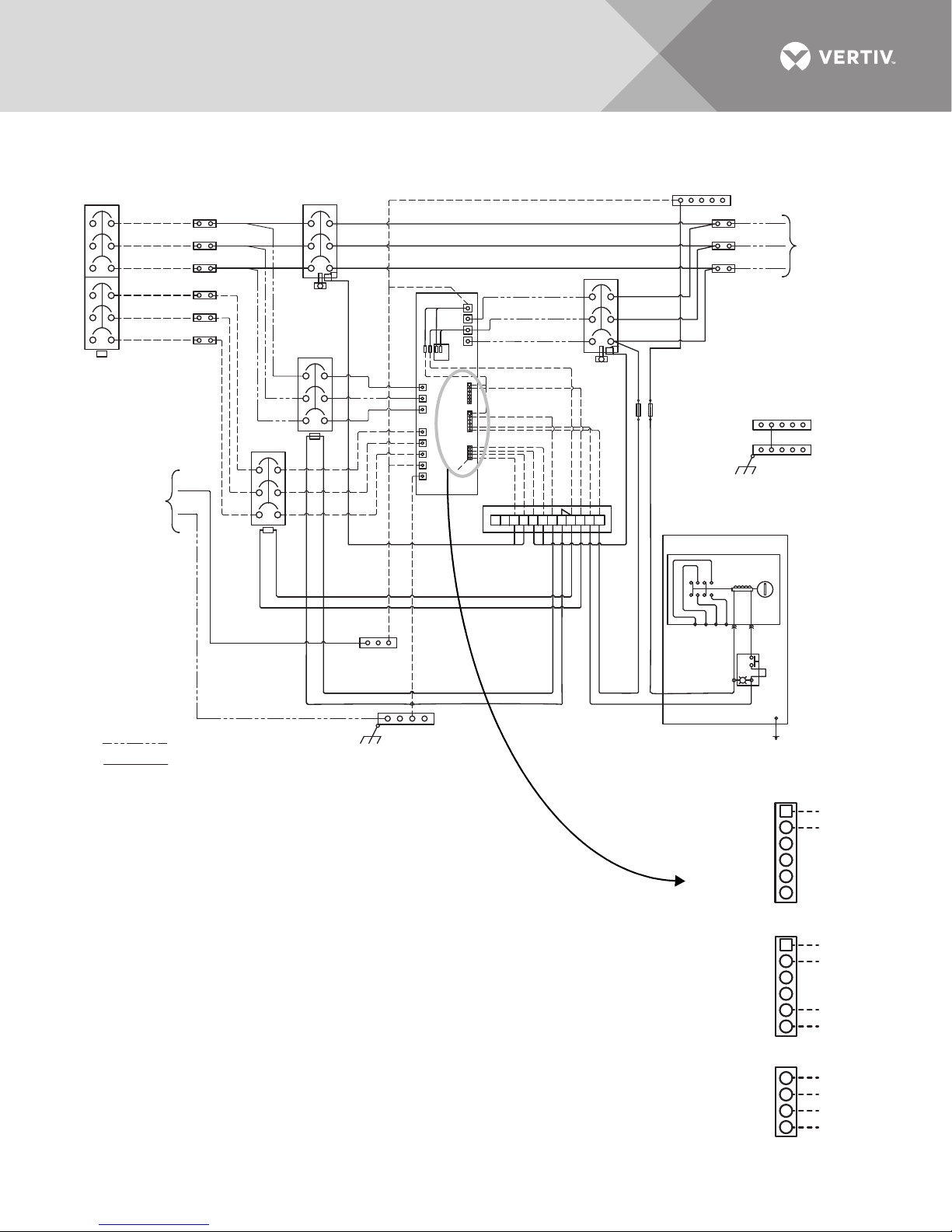
Figure 25 Control wiring diagram, Liebert EXM MBC, two to four breakers, with interlock
123456789101112
AUX
K0
3434
4
3
LAMP
704
710
R
W
AC 120V
Push
Button
702
703
706
100
oC
oA
oB
UPS
X9J26
X9J23
X9J24
oN
FH1
FH2
*Option
FUSE
BLK
INV_C
INV_S
MFP_S
MFP_O
INV_O
MFP_C
1
3
5
2
4
6
1
3
5
2
4
6
BFP_C
BFP_S
BFP_O
Main_abnl_O
Main_abnl_S
Main_abnl_C
15
13
11
9
Q3_STATUS
Q5_STATUS
GND_Dry
GND_Dry
14
AUX
EXM14004
Rev. 4
MBB See Note 5
Customer Feed
Output
Neutral
AC
Output
Kirk
Key K1
Kirk
Key K2
MIB
See Note 6
From
Utility
Output
Ground
Ground to
Unit Frame
Ground to
Unit Frame
Optional;
See Note 8
Input Neutral
See Note 1
SKRU - Solenoid Key Release Unit
KO-Key Operator
Main Ground Busbar
Field-Supplied Wiring
Inner Door
Factory-Supplied Wiring
ØA
ØC
ØA
ØB
ØC
ØA
ØB
ØC
RIB
BIB
W04
W05
W06
W87
W86
W85
W90
W89
W88
W07
W08
W09
TB1
2 Fuses,
2A
AC Output
AC Input
A
B
C
A
B
C
mN
PE
NOTES
1. Customer-furnished electrode conductor must be installed in accordance
with national and local electrical codes.
2. Overcurrent protection is based on 80% rated devices.
3. MBB auxiliary switch connections are on the normally closed and common positions.
4. MIB auxiliary switch connections are on the normally open and common positions.
5. MBC when connected to UPS module, all control and power wiring is supplied by Vertiv.
If the MBC is remote from the UPS module, the cables between the MBC and UPS module
must be supplied by others.
6. Optional SKRU and associated wiring (703, 704, 706).
7. Typical four-breaker configuration is shown. Also available: a two-breaker configuration
(MIB, MBB) and a three-breaker configuration (BIB, MIB, MBB).
8. If configuration is a two-breaker MBC, the customer must supply the120V shunt trip coil
for the bypass and rectifier.
L
SKRU
1
4
Wiring shown for a four-breaker system.
Refer to Notes 7 and 8 for two- and three-breaker
Detail A
DETAIL A
Vertiv™|Liebert® EXM™ MBC Installation Manual | 33
Main_abnl_O
Main_abnl_S
Main_abnl_C
Q5_STATUS
Q3_STATUS
X9J24
MFP_O
MFP_S
MFP_C
X9J23
BFP_O
BFP_S
BFP_C
INV_O
INV_S
INV_C
X9J26
GND_Dry
GND_Dry
1
3
5
2
4
6
1
3
5
2
4
6
15
13
11
9
Page 40
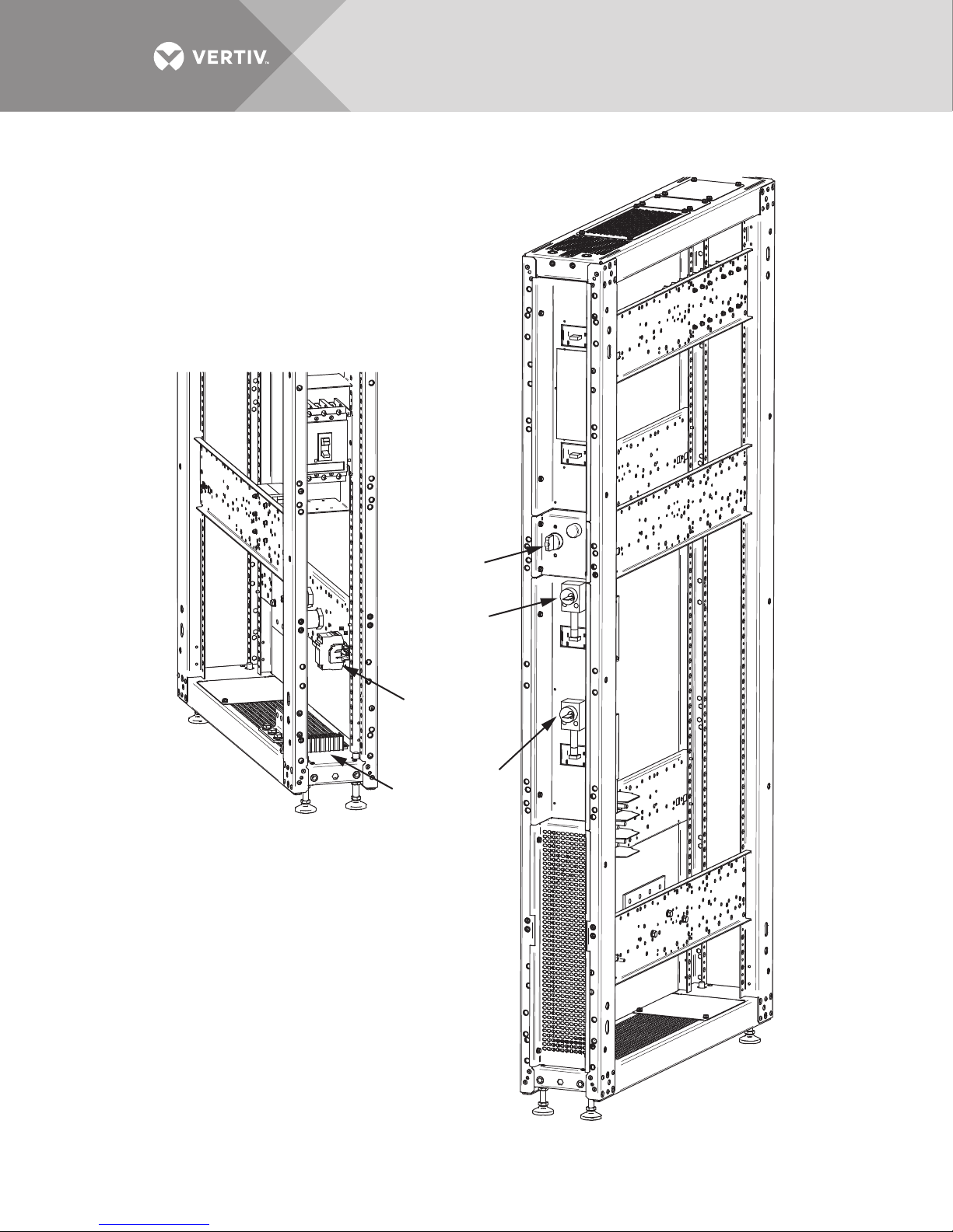
Figure 26 Solenoid key release unit, 200mm Liebert EXM MBC
K0
Fuseblock
for SKRU
TB1
Solenoid key release unit
is mounted between the
BIB and MBB breakers.
K1
K2
Vertiv™|Liebert® EXM™ MBC Installation Manual | 34
Page 41
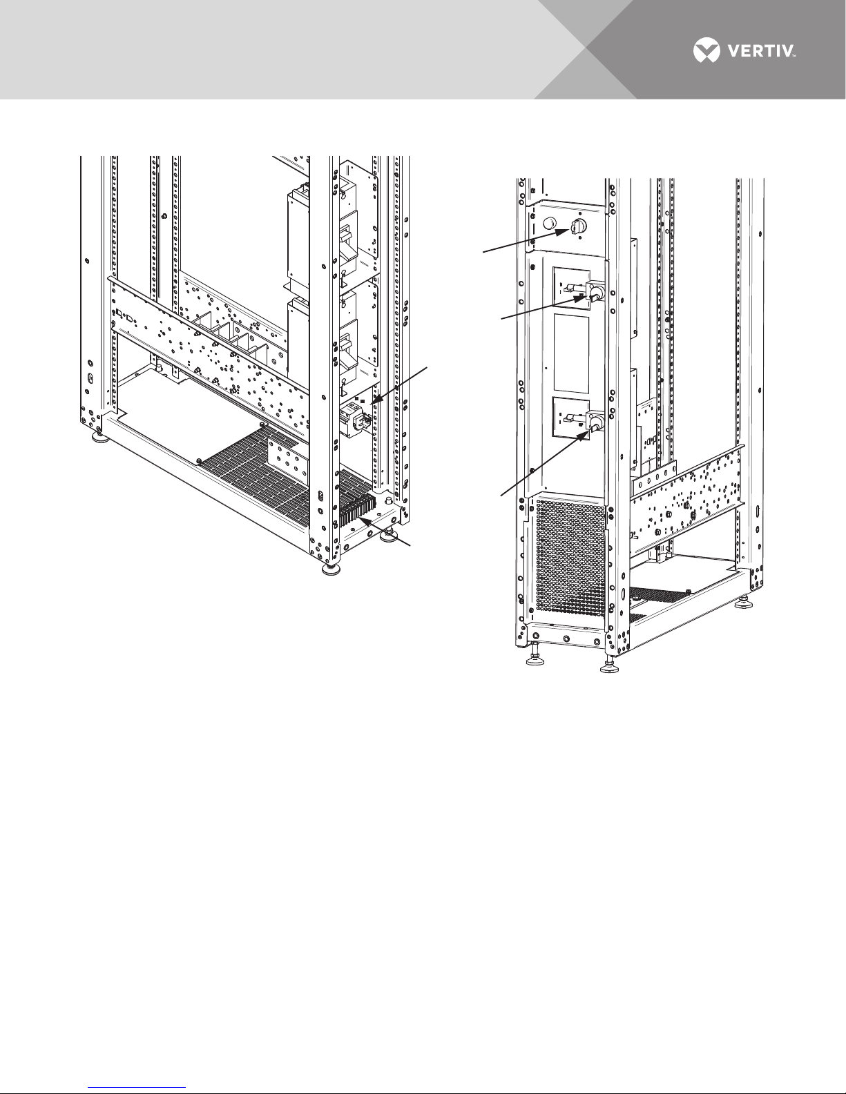
Figure 27 Solenoid key release unit, 300mm Liebert EXM MBC
K0
K1
K2
Solenoid key release unit
is mounted between the
BIB and MBB breakers.
TB1
Fuseblock
for SKRU
Vertiv™|Liebert® EXM™ MBC Installation Manual | 35
Page 42
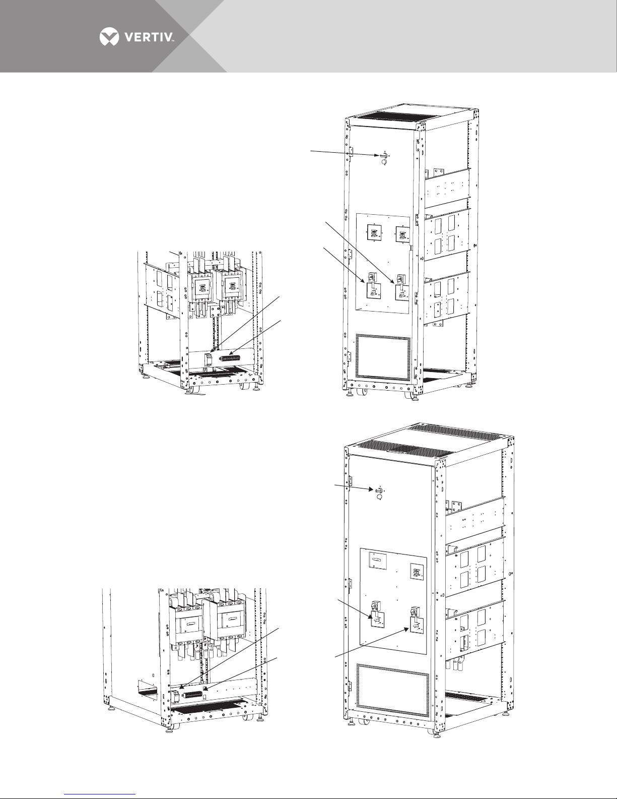
Figure 28 Solenoid key release unit, 600mm Liebert EXM MBC
K0
K1
TB1
Fuseblock
for SKRU
K2
TB1
Fuseblock
for SKRU
K0
K1
K2
Figure 29 Solenoid key release unit, 800mm Liebert EXM MBC
Vertiv™|Liebert® EXM™ MBC Installation Manual | 36
Page 43

3.0 SPECIFICATIONS
Table 10 Liebert EXM MBC specifications
Model Size 10-40kVA UPS 60-100kVA UPS 120-140kVA UPS 160-200kVA UPS
Input Parameters
Input Voltage to Bypass, VAC 208/120V or 220/127V, 3-Phase, 4-Wire
Input Current, AAC Refer to Tables 15, 16 and 17
Input Frequency, Hz 60
Output Parameters
Output Power, kW 10-40 60-100 120-140 160-200
Output Voltage, VAC 208/120V or 220/127V, 3-Phase, 4-Wire
Output Current, AAC Refer to Table 18
Output Frequency, Hz 60
Physical Parameters and Standards, in (mm)
Cabinet Width, in. (mm)
with side panels attached
Depth, in. (mm) 39.4 (1000)
Height, in. (mm) 78.74 (2000)
Weight, lb. (kg) 198 (90) 288 (131) 535 (243) 700 (318)
Color Black (ZP-7021)
Degree of Protection for UPS
Enclosure
Standards and Conformities UL1778 5th Edition; CSA 22.2 107-3-14; ISTA Procedure 1H; WEEE
Minimum Clearance, Top, in. (mm) 24 (610)
Minimum Clearance, Back, in. (mm) 0
Minimum Clearance, Sides, in. (mm) 0
Cable Entrance Top or Bottom
Environmental Parameters
Storage Temperature Range, °F (°C) -13 to 158 (-25 to 70)
Operating Temperature Range, °F
(°C
)
Relative Humidity Maximum 95% Non-Condensing (Operating and Non-Operating)
Maximum Altitude above MSL, ft.
(m)
8.2 (208) 12.0 (308) 23.9 (608) 31.8 (808)
IP 20 (with and without front door open)
0 to 40 (UPS)
Refer to UPS Manual, SL-25648 or SL-26100
Table 11 Dimensions for Liebert EXM UPS with Liebert EXM MBC
UPS Rating, kVA
10-40 60-100
Components
UPS Only
Dimensions, WxDxH, in. (mm)
23-5/8 x 39-1/2 x 78-
3/4
(600 x 1000 x 2000)
Vertiv™|Liebert® EXM™ MBC Installation Manual | 37
23-5/8 x 39-1/2 x 78-
3/4
(600 x 1000 x 2000)
Page 44
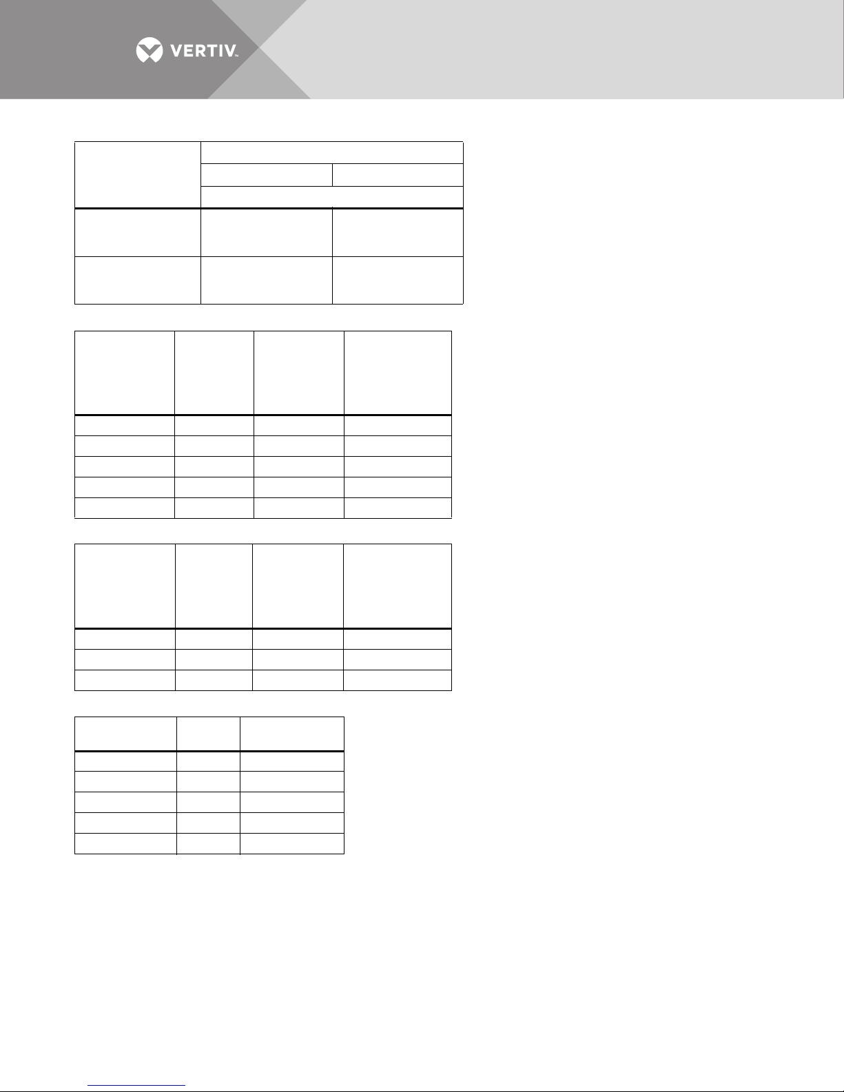
Table 11 Dimensions for Liebert EXM UPS with Liebert EXM MBC
UPS Rating, kVA
10-40 60-100
Components
UPS with 200mm
MBC
UPS with 300mm
MBC
Dimensions, WxDxH, in. (mm)
31-1/2 x 39-1/2 x 78-
3/4
(800 x 1000 x 2000)
—
—
35-1/2 x 39-1/2 x 78-
3/4
(900 x 1000 x 2000)
Table 12 Weights—Liebert EXM UPS, 10-40kVA, and 200mm Liebert EXM MBC
Liebert EXM
UPS Rating,
kVA
10 684 (310) 198 (90) 882 (400)
15 684 (310) 198 (90) 882 (400)
20 684 (310) 198 (90) 882 (400)
30 758 (344) 198 (90) 956 (434)
40 758 (344) 198 (90) 956 (434)
UPS
Weight
lb (kg)
MBC
200mm
Weight, lb
(kg)
Combined
Weight
UPS and
Liebert
EXM MBC, lb
(kg)
Table 13 Weights—Liebert EXM UPS, 60-100kVA, and 300mm Liebert EXM MBC
Liebert EXM
UPS Rating,
kVA
60kVA 844 (383) 288 (131) 1132 (514)
80kVA 918 (416) 288 (131) 1206 (547)
100kVA 992 (450) 288 (131) 1280 (581)
UPS
Weight
lb (kg)
MBC,
300mm
Weight, lb
(kg)
Combined
Weight
UPS and
Liebert
EXM MBC, lb
(kg)
Table 14 Additional weight for Liebert EXM 10-40kVA UPS with internal batteries *
Battery Model
12HX100-FR F 528 (240)
12HX150-FR H 624 (283)
12HX205-FR M 1032 (468)
HR1500 G 648 (294)
HR2000 L 960 (435)
* For total system weight, add the weight for the UPS, Liebert EXM MBC and the Liebert EXM 10-40kVA UPS
internal batteries.
Battery
Code
Added Battery
Weight, lb (kg)
Vertiv™|Liebert® EXM™ MBC Installation Manual | 38
Page 45

3.1 Electrical Characteristics
NOTE
The breakers and cables used must be in accordance with NEC ANSI/NFPA 70. A disconnect
breaker must be provided for AC input, Bypass and AC output. Recommended cable sizes are
suitable for operation at a maximum temperature of 104°F (40°C).
Table 15 Liebert EXM MBC input currents, single input, main
Vol tag e
3-Ph, 60
Hz
208/120
220/127
208/120
220/127
208/120
220/127
208/120
220/127
208/120
220/127
208/120
220/127
208/120
220/127
208/120
220/127
208/120
220/127
208/120
220/127
208/120
220/127
208/120
220/127
208/120
220/127
MBC
Rating
kVA
10 34
15 51
20 68
30 102
40 136
60 205
80 273
100 341
120 409
140 478
160 546
180 614
200 682
System Input
Current A,
Max Phase
3W + N +
G
3W + N +
G
3W + N +
G
3W + N +
G
3W + N +
G
3W + N +
G
3W + N +
G
3W + N +
G
3W + N +
G
3W + N +
G
3W + N +
G
3W + N +
G
3W + N +
G
Recommended
Upstream
Protection, A
45 65 (1) #6 (1) #4 M10
70 85 (1) #4 (1) #2 M10
90 115 (1) #2 (1) 1/0 M10
150 175 (1) 2/0 (1) 4/0 M10
175 230 (1) 4/0 (2) 1/0 M10
300 400 (2) 3/0 (2) 4/0 M10
350 460 (2) 4/0 (2) 300 M10
450 610 (2) 350 (2) 400 M10
600 760 (2) 500 (3) 350 M12
600 760 (2) 500 (3) 350 M12
700 930 (3) 350 (3) 500 M12
800 1140 (3) 500 (4) 400 M12
1000 1240 (4) 350 (4) 500 M12
75°C Wire
Current A,
To tal
Copper
Wire
Aluminu
m
Wire
Bolt
Size
Vertiv™|Liebert® EXM™ MBC Installation Manual | 39
Page 46

Table 16 Liebert EXM MBC input currents, dual input, rectifier
Vol tag e
3-Phase
60Hz
208/120
220/127
208/120
220/127
208/120
220/127
208/120
220/127
208/120
220/127
208/120
220/127
208/120
220/127
208/120
220/127
208/120
220/127
208/120
220/127
208/120
220/127
208/120
220/127
208/120
220/127
MBC
Rating
kVA
10 34 45
15 51 70
20 68 90
30 102 150
40 136 175
60 205 300
80 273 350
100 341 450
120 409 600
140 478 600
160 546 700
180 614 800
200 682 1000
Rectifier Input
Current RIB A,
Max
Rectifier
Recommended
Upstream
Protection, A Phase
3W + N +
3W + N +
3W + N +
3W + N +
3W + N +
3W + N +
3W + N +
3W + N +
3W + N +
3W + N +
3W + N +
3W + N +
3W + N +
75°C Wire
Current A,
Tot al
G
G
G
G
G
G
G
G
G
G
G
G
G
65 (1) #6 (1) #4 M10
85 (1) #3 (1) #2 M10
115 (1) #2 (1) 1/0 M10
175 (1) 2/0 (1) 4/0 M10
230 (1) 4/0 (2) 1/0 M10
400 (2) 3/0 (2) 4/0 M10
460
610
760
760
930
1140
1240
Coppe
r
Wire
(2)
4/0
(2)
350
(2)
500
(2)
500
(3)
350
(3)
500
(4)
350
Aluminu
m
Wire
(2) 300 M10
(2) 400 M10
(3) 350 M12
(3) 350 M12
(3) 500 M12
(4) 400 M12
(4) 500 M12
Bolt
Size
Vertiv™|Liebert® EXM™ MBC Installation Manual | 40
Page 47

Table 17 Liebert EXM MBC input currents, dual input, bypass
Vol tag e
3-Ph, 60
Hz
208/120
220/127
208/120
220/127
208/120
220/127
208/120
220/127
208/120
220/127
208/120
220/127
208/120
220/127
208/120
220/127
208/120
220/127
208/120
220/127
208/120
220/127
208/120
220/127
208/120
220/127
MBC
Rating
kVA
10 28 40
15 42 60
20 56 70
30 83 110
40 111 150
60 167 225
80 222 300
100 278 350
120 333 450
140 389 500
160 444 600
180 500 700
200 555 700
Bypass Input
Current
BIB/MBB
A, Max
Bypass
Recommended
Upstream
Protection, A Phase
3W + N +
G
3W + N +
G
3W + N +
G
3W + N +
G
3W + N +
G
3W + N +
G
3W + N +
G
3W + N +
G
3W + N +
G
3W + N +
G
3W + N +
G
3W + N +
G
3W + N +
G
75°C Wire
Current
A Total
50 (1) #6 (1) #4 M10
85 (1) #4 (1) #2 M10
115 (1) #2 (1) #2 M10
130 (1) 1/0 (1) 2/0 M10
175 (1) 3/0 (1) 4/0 M10
285 (2) 300 (2) 2/0 M10
400 (2) 3/0 (2) 4/0 M10
460 (2) 4/0 (2) 300 M10
620 (2) 350 (2) 500 M12
620 (2) 350 (2) 500 M12
760 (2) 500 (3) 350 M12
930 (3) 350 (3) 500 M12
930 (3) 350 (3) 500 M12
Copper
Wire
Aluminu
m
Wire
Bolt
Size
Vertiv™|Liebert® EXM™ MBC Installation Manual | 41
Page 48

Table 18 Liebert EXM MBC output currents
System
Output
Current, A,
Max Phase
Vol tag e
3-Ph, 60Hz)
208/120
220/127
208/120
220/127
208/120
220/127
208/120
220/127
208/120
220/127
208/120
220/127
208/120
220/127
208/120
220/127
208/120
220/127
208/120
220/127
208/120
220/127
208/120
220/127
208/120
220/127
MBC
Rating,
kVA
10 28 3W + N + G 40 50 (1) #6 (1) #4 M10
15 42 3W + N + G 60 85 (1) #4 (1) #2 M10
20 56 3W + N + G 70 115 (1) #2 (1) #2 M10
30 83 3W + N + G 110 130 (1) 1/0 (1) 2/0 M10
40 111 3W + N + G 150 175 (1) 3/0 (1) 4/0 M10
60 167 3W + N + G 225 285
80 222 3W + N + G 300 400 (2) 3/0 (2) 4/0 M10
100 278 3W + N + G 350 460 (2) 4/0
120 333 3W + N + G 450 620 (2) 350 (2) 500 M12
140 389 3W + N + G 500 620 (2) 350 (2) 500 M12
160 444 3W + N + G 600 760 (2) 500 (3) 350 M12
180 500 3W + N + G 700 930 (3) 350 (3) 500 M12
200 555 3W + N + G 700 930 (3) 350 (3) 500 M12
Recommend
ed
Upstream
Protection,
A)
75°C Wire
Current A,
To tal
Copper
Wire
(2)
300kcmil
Aluminum
Wire Bolt Size
(2) 2/0 M10
(2)
300kcmil
M10
Table 19 Recommended lug sizes (compression type) M10, 3/8" bolt
Cable Size
#8AWG 54132 60104-TB
#6AWG 54136 60109
#4AWG 54140 60114
#2AWG 54143 60118
#1AWG 54148 60124
#1/0AWG 54109 60130
#2/0AWG 54110 60136
#3/0AWG 54111 60142
#4/0AWG 54112 60148
T&B Copper
One Hole
Vertiv™|Liebert® EXM™ MBC Installation Manual | 42
T&B Aluminum
One Hole
Page 49
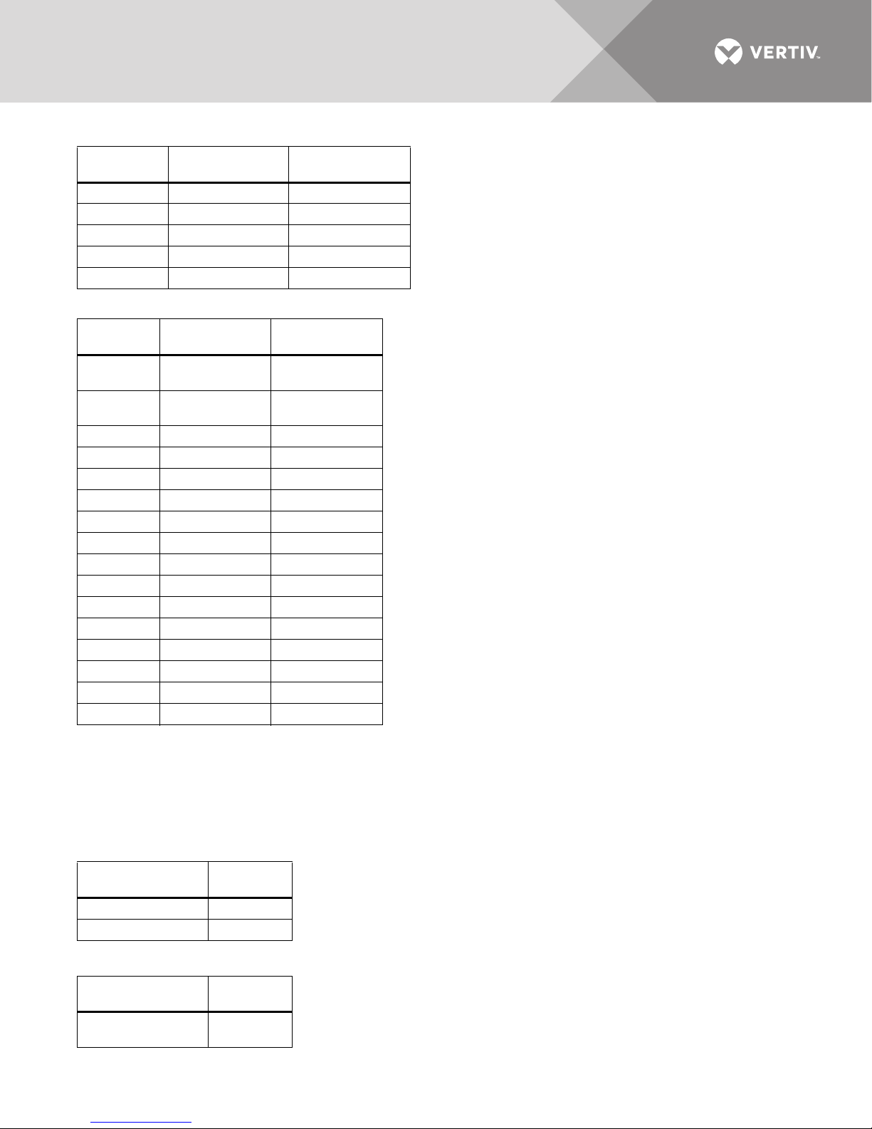
Table 19 Recommended lug sizes (compression type) M10, 3/8" bolt
Cable Size
250kcmil 54174 60154
300kcmil 54179 60160
350kcmil 256-30695-112 —
400kcmil 256-30695-1403 —
500kcmil 256-30695-339 —
T&B Copper
One Hole
T&B Aluminum
One Hole
Table 20 Recommended lug sizes (Compression Type) M12, 1/2" bolt
Cable Size
#6AWG
#4AWG
#2-3AWG 54811BE —
#1AWG 54857BE —
#1/0AWG 256-30695-593 —
#2/0AWG 54862BE 60238
#3/0AWG 54864BE 60244
#4/0AWG 54866BE 60250
250kcmil 54868BE 60256
300kcmil 54870BE 60262
350kcmil 54872BE 60267
400kcmil 54874BE 60269
500kcmil 54876BE 60273
600kcmil 54878BE 60275
700kcmil 54879BE 60277
750kcmil 54880BE 60278
T&B Copper
Two -Hole
256-030695-
868
256-030695-
733
T&B Aluminum
Two -Hole
—
—
3.2 Torque Requirements
All electrical connections must be tight.
Tables 21 and 22 provide the torque values for the connections to the Liebert EXM MBC. Use
these values unless the equipment is labeled otherwise.
Table 21 Busbar torque for power wiring
Bolt Shaft Size
3/8" (M10) 192 (22)
1/2" (M12) 428 (48)
Table 22 Terminal block torque with compression lugs for control wiring
AWG Wire Size
or Range
#22 - #14
Vertiv™|Liebert® EXM™ MBC Installation Manual | 43
Tor qu e
Lb-in (Nm)
Tor qu e
Lb-in (Nm)
3.5 to 5.3
(0.4 to 0.6)
Page 50

NOTE
Refer to the manufacturer’s data for proper torque for circuit breaker power connections.
Vertiv™|Liebert® EXM™ MBC Installation Manual | 44
Page 51

NOTES
Vertiv™|Liebert® EXM™ MBC Installation Manual | 45
Page 52

Vertiv™|Liebert® EXM™ MBC Installation Manual | 46
Page 53

Page 54

VertivCo.com | Vertiv Headquarters, 1050 Dearborn Drive, Columbus, OH, 43085, USA
© 2018 Vertiv Co. All rights reserved. Vertiv and the Vertiv logo are trademarks or registered trademarks of Vertiv Co. All other names and logos referred to
are trade names, trademarks or registered trademarks of their respective owners. While every precaution has been taken to ensure accuracy and
completeness herein, Vertiv Co. assumes no responsibility, and disclaims all liability, for damages resulting from use of this information or for any errors or
omissions. Specifications are subject to change without notice.
SL-25652_REV5_8-18
 Loading...