

Page 1

Liebert® DS
ThermalManagementSystem
System Design Catalog
35to 105kW (10to 30ton) Capacity, UpflowandDownflow,60Hz, Air
Cooled, Water/Glycol Cooled, GLYCOOLEconomizerCoil,
Dual-CoolDXwithSecondaryChilled WaterCoil
Page 2

Vertiv™ Liebert® DS System Design Catalog
The information contained in this document is subject to change without notice
and may not be suitable for all applications. While every precaution has been
taken to ensure the accuracy and completeness of this document, Vertiv
assumes no responsibility and disclaims all liability for damages resulting from
use of this information or for any errors or omissions.
Refer to local regulations and building codes relating to the application,
installation, and operation of this product. The consulting engineer, installer,
and/or end user is responsible for compliance with all applicable laws and
regulations relating to the application, installation, and operation of this product.
The products covered by this instruction manual are manufactured and/or sold
by Vertiv. This document is the property of Vertiv and contains confidential and
proprietary information owned by Vertiv. Any copying, use, or disclosure of it
without the written permission of Vertiv is strictly prohibited.
Names of companies and products are trademarks or registered trademarks of
the respective companies. Any questions regarding usage of trademark names
should be directed to the original manufacturer.
Technical Support Site
If you encounter any installation or operational issues with your product, check the pertinent section of this
manual to see if the issue can be resolved by following outlined procedures.
Visit https://www.vertiv.com/en-us/support/ for additional assistance.
Vertiv™ | Liebert® DS System Design Catalog
Page 3

Vertiv™ Liebert® DS System Design Catalog
TABLE OF CONTENTS
1 Nomenclature and Components 1
1.1 Vertiv™ Liebert® DS Model Number Nomenclature 1
1.2 Component Location 3
1.3 Cooling Configurations 3
1.4 Blower Configurations 4
2 System Data 9
2.1 Air Cooled Capacity and Performance Data 9
2.2 Water Cooled Capacity and Performance Data 15
2.3 Glycol Cooled Capacity and Performance Data 31
2.4 Vertiv™ Liebert® Econ-o-Coil and GLYCOOL Capacity and Performance Data 37
2.5 Physical Data 48
3 Electrical Power Requirements 51
3.1 Air Cooled Electrical Data 51
3.2 Water/Glycol Cooled Electrical Data 58
3.3 Electrical Field Connections 65
4 Planning Guidelines 67
4.1 Shipping Dimensions andUnitWeights 67
4.2 Planning Dimensions 70
5 Piping 71
5.1 Refrigerant Piping 73
5.1.1 Refrigerant Line Sizes and Equivalent Lengths 73
5.1.2 Refrigerant Charge Requirements for Air Cooled Systems 73
6 Heat Rejection—Vertiv™ Liebert® MC Condensers 75
6.1 Vertiv™ Liebert® MC Match-up Selections 75
6.2 Vertiv™ Liebert® MC Sound Data 76
6.3 Electrical Power Requirements 76
6.4 Vertiv™ Liebert® MC Shipping Dimensions and Weights 78
6.4.1 Condenser and Options Net Weights 78
6.5 Vertiv™ Liebert® MC Planning Dimensions 79
6.6 Vertiv™ Liebert® MC Piping 79
6.7 Vertiv™ Liebert® MC Electrical Field Connections 80
7 Heat Rejection—Vertiv™ Liebert® Drycoolers and Pumps 81
7.1 Vertiv™ Liebert® Drycooler Match-up Selections 81
7.2 Vertiv™ Liebert® Drycooler Electrical Power Requirements 83
7.3 Vertiv™ Liebert® Drycooler Planning Dimensions 87
7.4 Vertiv™ Liebert® Drycooler Piping Guidelines 87
7.5 Vertiv™ Liebert® Drycooler Electrical Field Connections 88
7.6 Vertiv™ Liebert® Drycooler Pump Packages 88
i
Proprietary and Confidential ©2023 Vertiv Group Corp.
Page 4

Vertiv™ Liebert® DS System Design Catalog
7.6.1 Vertiv™ Liebert® Drycooler Expansion Tank 89
7.6.2 Tank 89
Appendices 91
Appendix A: Technical Support and Contacts 91
Appendix B: Disassembling the Vertiv™ Liebert® DS for Transport 93
Appendix C: Submittal Drawings 95
Appendix D: Guide Specifications 99
ii
Proprietary and Confidential ©2023 Vertiv Group Corp.
Page 5
Vertiv™ Liebert® DS System Design Catalog
1 Nomenclature and Components
This section describes the model number for Vertiv™ Liebert® DS units and components.
1.1 Vertiv™ Liebert® DS Model Number Nomenclature
Table 1.2 below describes each digit of the model number.
Table 1.1 Liebert® DS Model Number Example
1 2 3 4 5 6 7 8 9 10 11 12 13 14 15
D S 0 3 5 A D A 1 E I * * * *
Table 1.2 Liebert® DS Model Number Digit Definitions
Digit Description
Digits 1 and 2 = Airflow Distribution
DS = Downflow standard
VS = Upflow standard
Digit 3, 4, 5 = Nominal Cooling Capacity, kW
035 = 35 kW, 10 ton
042 = 42 kW, 12 ton
053 = 53 kW, 15 ton
070 = 70 kW, 20 ton
077 = 77 kW, 22 ton
105 = 105 kW, 30 ton
Digit 6 = Cooling Type
A = Air-cooled
D = Dual-cool, air cooled
H = Dual-cool, water cooled
K = GLYCOOL (Liebert® Economizer Coil)
W = Water/Glycol cooled
Digit 7 = Compressor Type
D = Digital scroll, R-407C
S = Scroll, R-407C
U = Semi-hermetic with 4-step, R-407C
V = Semi-hermetic with 4-step, R-407C
(DS105 water/glycol/GLYCOOL only)
1 Nomenclature and Components
1
Proprietary and Confidential ©2023 Vertiv Group Corp.
Page 6
Vertiv™ Liebert® DS System Design Catalog
Table 1.2 Liebert® DS Model Number Digit Definitions (continued)
Digit Description
Digit 8 = Voltage
A = 460V - 3ph - 60Hz
B = 575V - 3ph - 60Hz
C = 208V - 3ph - 60Hz
D = 230V - 3ph - 60Hz
2 = 380V - 3ph - 60Hz
Digit 9 = Fan Type
0 = Forward-curved blowers
1 = Electronically-commutated (EC) fans
Digit 10 = Reheat Type
0 = None
E = 3-stage electric
R = Reduced, 3-stage electric
Digit 11 = Humidifier
0 = No humidifier
I = Infrared Humidifier
Digit 12-15 = Factory Configuration Number
Not all combinations of options are available on all units:
• Digital Scroll Compressors
• Not available on VS042A with forward-curved blower
• Not available on 077 and 105 models
• 575-V available only on 035, 053 and 070 models
• Scroll Compressors
• Available on air cooled models 035–105
• Available on water/glycol models 035–070
• Scroll compressors not available on 77- and 105-kW models for water/glycol/GLYCOOL/DualCool units
• GLYCOOL Vertiv™ Liebert® Econ-o-Coil Models
• Available with digital scroll compressors on 035 to 070 models, and with semi-hermetic compressors on
077 to 105 models
• High Pressure Water Regulating Valve
• Not available on 042, 053, 070 and 077 models with semi-hermetic and scroll compressors
2
1 Nomenclature and Components
Proprietary and Confidential ©2023 Vertiv Group Corp.
Page 7
Vertiv™ Liebert® DS System Design Catalog
1.2 Component Location
The unit component locations are described in the submittal documents included in Submittal Drawings on page95 .
The following table lists the relevant documents by number and title.
Table 1.3 Component Location Drawings
Document Number Title
DPN003706 Component Location, Downflow Models
DPN003707 Component Location, Upflow Models
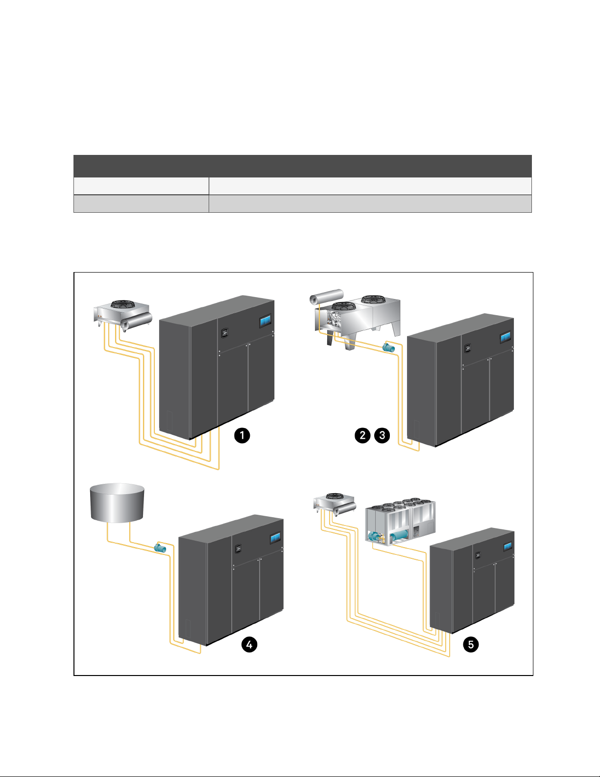
1.3 Cooling Configurations
Figure 1.1 Cooling Configurations for the Vertiv™ Liebert® DS
1 Nomenclature and Components
3
Proprietary and Confidential ©2023 Vertiv Group Corp.
Page 8
Vertiv™ Liebert® DS System Design Catalog
Table 1.4 Vertiv™ Liebert® DS Cooling Descriptions
Item Description
1
2
3
4
5
Air Cooled—Unit piping is spun closed from the factory and contains a nitrogen holding charge. Each installation requires refrigerant piping
to a condenser.
Glycol Cooled—Units are factory-charged and tested. Field-supplied and field-installed piping is required from the unit to the Liebert®
drycooler and pump package.
GLYCOOL-Integrated Fluid Economizer—Units are factory charged and tested. Field supplied and field installed piping is required from the
unit to the Liebert® Drycooler and pump package. An additional Liebert® Economizer coil is included for use when fluid temperatures are
sufficiently low (below room temperature). Economizer cooling is provided by circulating cold glycol through this second coil, reducing or
eliminating compressor operation.
Water Cooled—Units are factory-charged and tested. Field-supplied and field-installed water piping is required from the unit to the cooling
tower.
DUAL-COOL—System has all of the features of a compressorized system, but adds a second cooling coil that is connected to a source of
chilled water. Cooling is provided by circulating chilled water, when available, through this second coil and reducing compressor operation.
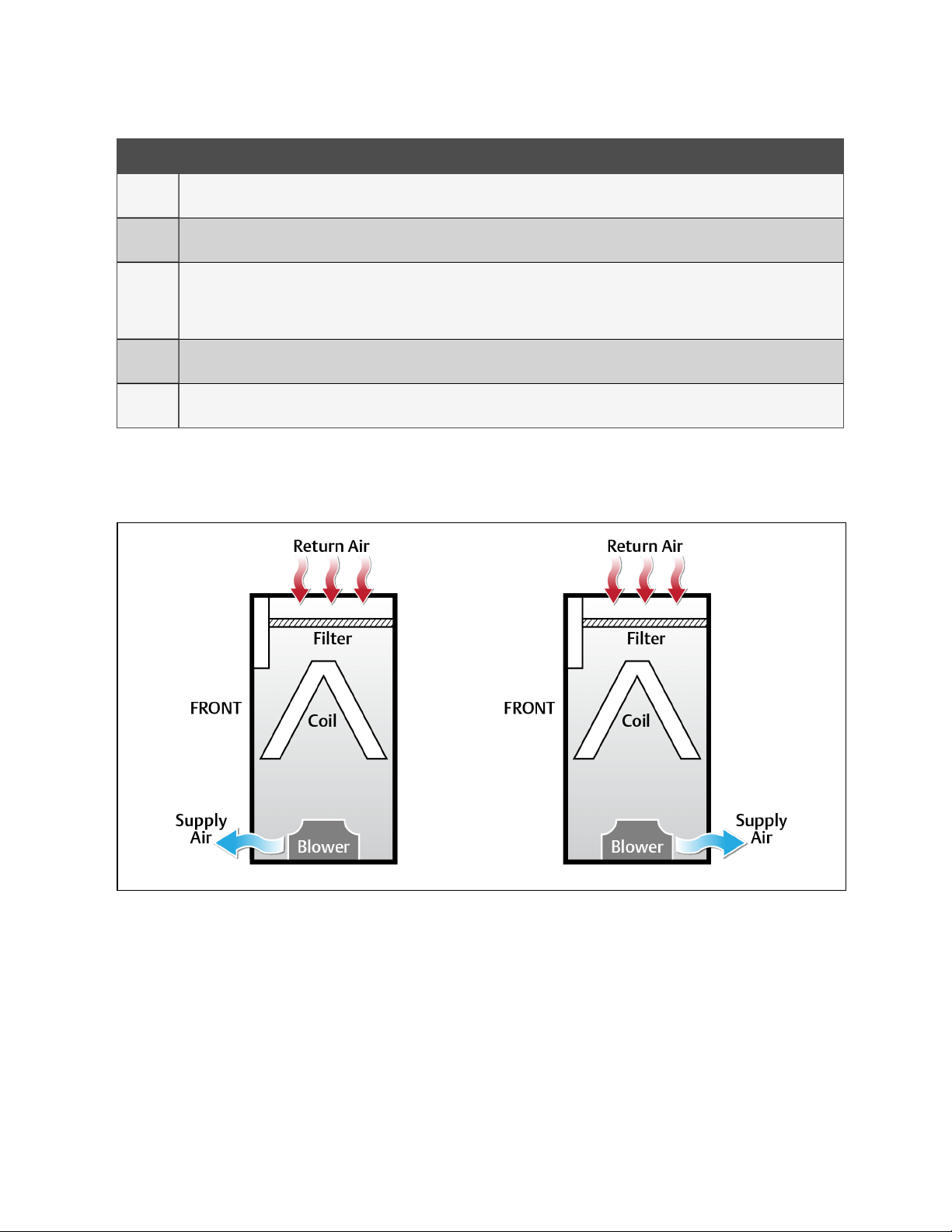
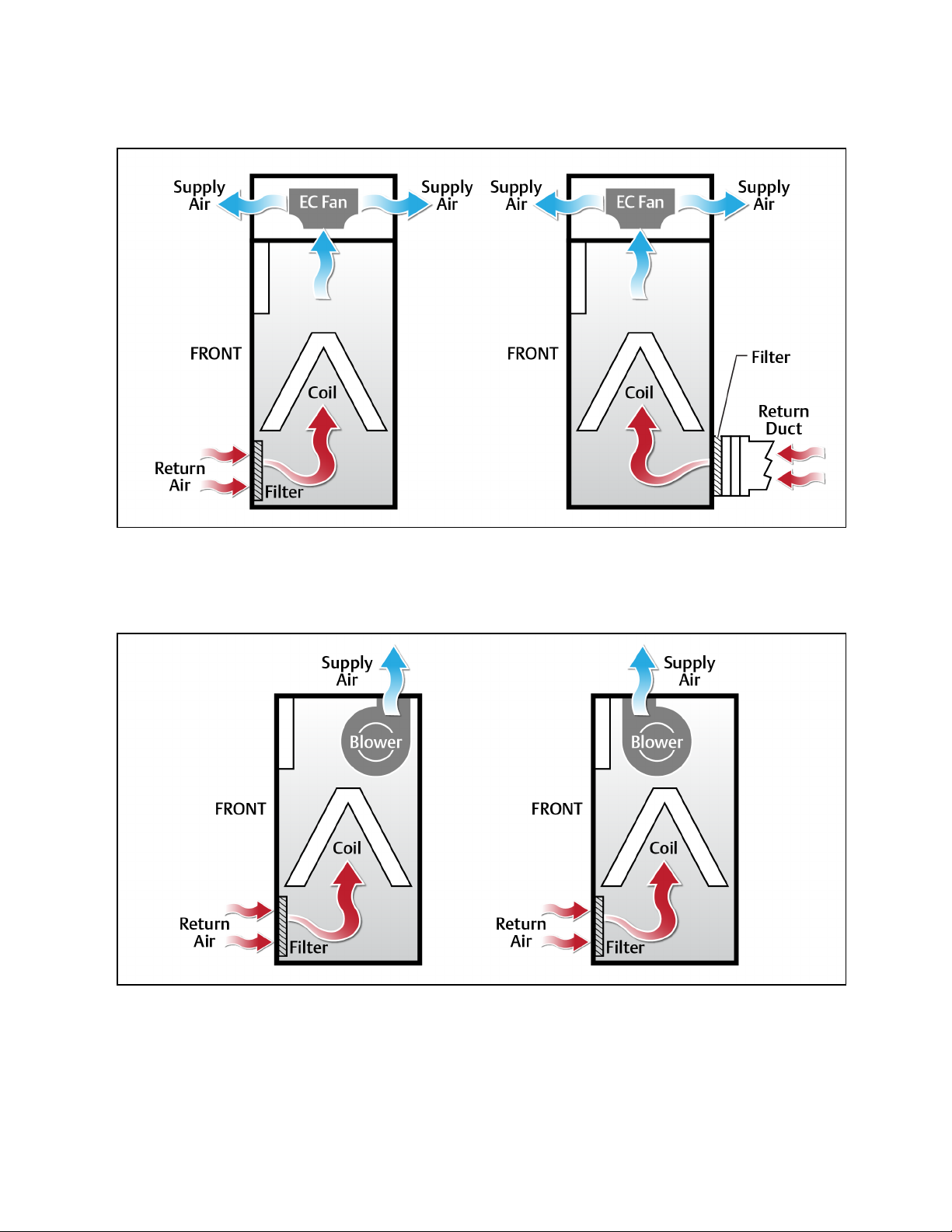
1.4 Blower Configurations
Figure 1.2 Downflow Blower Configurations, Front and Rear Supply with EC Fans
4
1 Nomenclature and Components
Proprietary and Confidential ©2023 Vertiv Group Corp.
Page 9
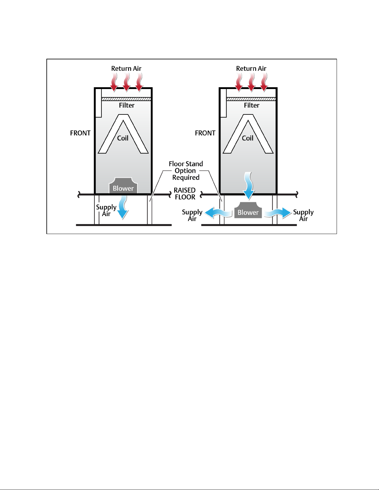
Figure 1.3 Downflow Blower Configurations, Bottom and Under-floor Supply with EC Fans
Vertiv™ Liebert® DS System Design Catalog
NOTE: Under-floor supply-air EC fans requires a minimum height of 24-in.
1 Nomenclature and Components
5
Proprietary and Confidential ©2023 Vertiv Group Corp.
Page 10
Vertiv™ Liebert® DS System Design Catalog
Figure 1.4 Upflow Blower Configurations with ECFans in a Plenum
NOTE: In upflow units with EC fans in the plenum, supply air exits the front or rear only. Figure 1.4 above represents
the possible options.
Figure 1.5 Upflow Blower Configurations, Front Return with Forward Curved Blowers
6
1 Nomenclature and Components
Proprietary and Confidential ©2023 Vertiv Group Corp.
Page 11
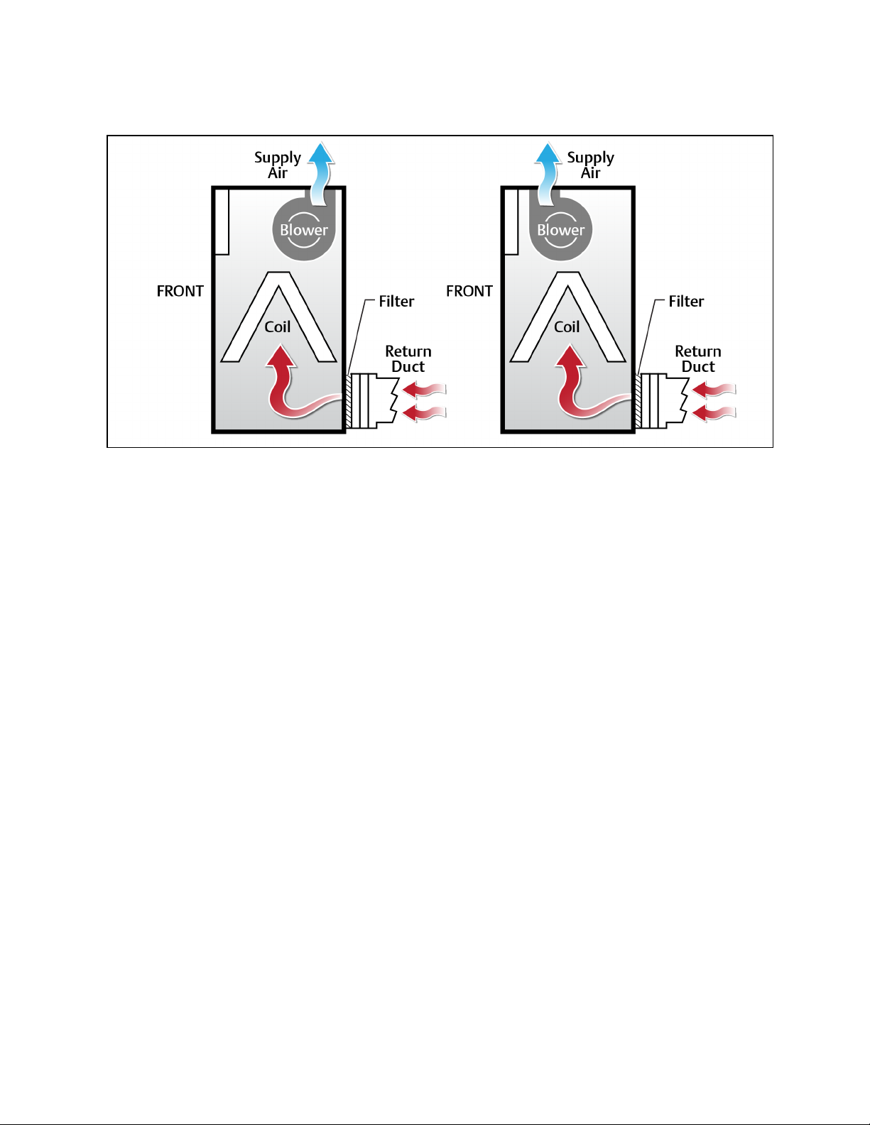
Figure 1.6 Upflow Blower Configurations, Rear Return with Forward Curved Blowers
Vertiv™ Liebert® DS System Design Catalog
1 Nomenclature and Components
7
Proprietary and Confidential ©2023 Vertiv Group Corp.
Page 12

Vertiv™ Liebert® DS System Design Catalog
This page intentionally left blank
8
1 Nomenclature and Components
Proprietary and Confidential ©2023 Vertiv Group Corp.
Page 13
Vertiv™ Liebert® DS System Design Catalog
2 System Data
2.1 Air Cooled Capacity and Performance Data
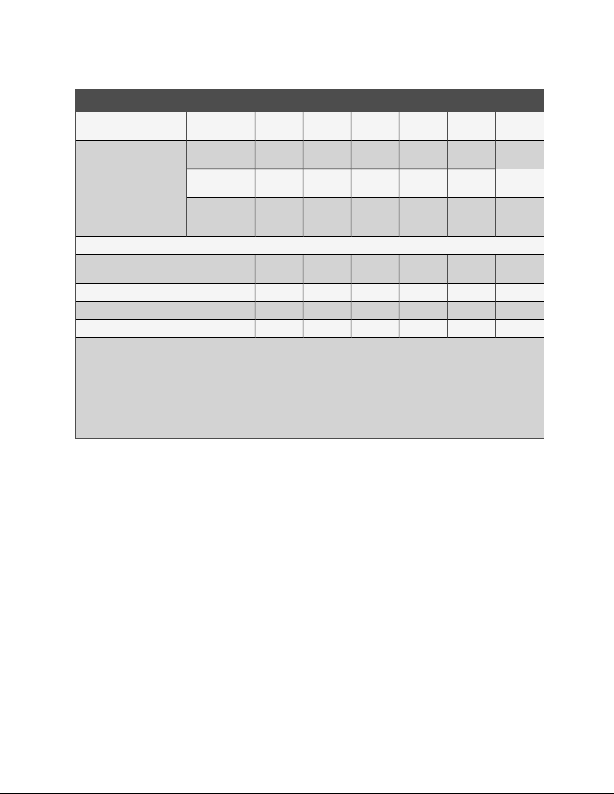
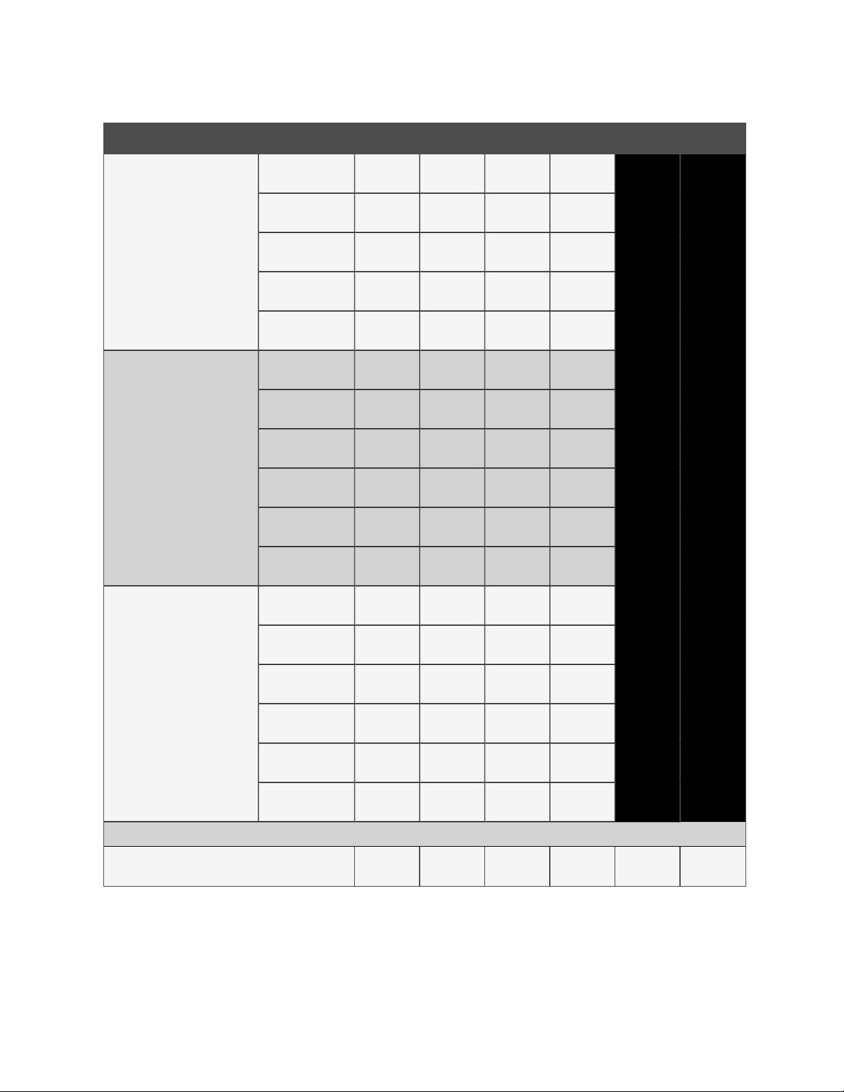
Table 2.1 Air Cooled Data for Downflow with EC Fan(s), 60 Hz Models
Model Size - Downflow Configuration DS035 DS042 DS053 DS070 DS077 DS105
DX Evaporator - Net Capacity Data at 95°F (35°C) Outdoor Ambient
Compressor Type Digital Scroll
Microchannel Liebert® MC Match-up at 95°F (35°C)
Outdoor Ambient
85°F DB1, 64.4°F WB, 52°F DP,
32%RH (29.4°C DB, 18°C WB)
80°F DB, 62.7°F WB, 52°F DP,
38%RH (26.7°C DB, 17.1°C WB)
75°F DB2, 61°F WB, 52°F DP,
44%RH (23.9°C DB, 16.1°C WB)
Compressor Type Scroll (Two Step Cooling)
Microchannel Liebert® MC Match-up at 95°F (35°C)
Outdoor Ambient
85°F DB1, 64.4°F WB, 52°F DP,
32%RH (29.4°C DB, 18°C WB)
Total, kW (BTUH)
Sensible, kW
(BTUH)
Total, kW (BTUH)
Sensible, kW
(BTUH)
Total. kW (BTUH)
Sensible, kW
(BTUH)
Total, kW (BTUH)
Sensible, kW
(BTUH)
MCS056 MCS056 MCS056 MCM080 MCM080 MCL110
39.3
(134,000)
39.3
(134,000)
37.4
(127,000)
36.2
(123,000)
35.9
(122,000)
32,3
(110,000)
MCS056 MCS056 MCS056 MCM080 MCM080 MCL110
39.6
(135,000)
39.5
(134,000)
43.1
(147,000)
43.1
(147,000
40.9
(139,000)
40.1
(136.000)
39.2
(133,000)
35.9
(122,000)
43.4
(148,000)
43.4
(148,000)
59.8
(204,000)
59.8
(204,000)
56.9
(194,000)
55.4
(189,000)
54.3
(185,000)
49.8
(1699,000)
60.6
(206,000)
60.5
(206,000)
74.1
(252,000)
73.2
(249,000)
70.9
(241,000)
67.3
(229,000)
68.1
(232,000)
60.2
(205,000)
75.7
(258,000)
74.5
(254,000)
Semi-hermetic (Four Step
Cooling)
79.2
(270,000)
78.7
(268,000)
75.4
(257,000)
72.4
(247,000)
72.2
(246,000)
64.7
(220,000)
81.3
(277,000)
80.4
(274,000)
105.6
(360,000)
101.1
(344,000)
101.3
(345,000)
92.2
(314,000)
97.4
(332,000)
82.2
(280,000)
105.9
(361,000)
101.3
(345,000)
2 System Data
80°F DB, 62.7°F WB, 52°F DP,
38%RH (26.7°C DB, 17.1°C WB)
75°F DB2, 61°F WB, 5.2°FDP,
44%RH (23.9°C DB, 16.1°C WB)
FANSECTION - EC Down
Return Air Volume, ACFM (ACMH)
Total, kW (BTUH)
Sensible, kW
(BTUH)
Total, kW (BTUH)
Sensible, kW
(BTUH)
37.8
(128,000)
36.4
(124,000)
36.3
(123,000)
32.5
(110,000)
5,200
(8,835)
41.3
(140,000)
40.3
(137,000)
39.6
(135,000)
36.1
(123,000)
6,200
(10,534)
57.8
(197,000)
56.1
(191,000)
55.4
(189,000)
50.4
(171,000)
8,000
(13,592)
Proprietary and Confidential ©2023 Vertiv Group Corp.
72.6
(247,000)
68.3
(233,000)
69.9
(238,000)
61.1
(208,000)
9,600
(16,310)
77.8
(265,000)
73.9
(252,000)
75.0
(255,000)
64.2
(219,000)
11,000
(18,689)
2a
2a
101.9
(347,000)
92.5
(315,000)
98.2
(335,000)
82.5
(281,000)
13,700
(23,276)
9
Page 14
Vertiv™ Liebert® DS System Design Catalog
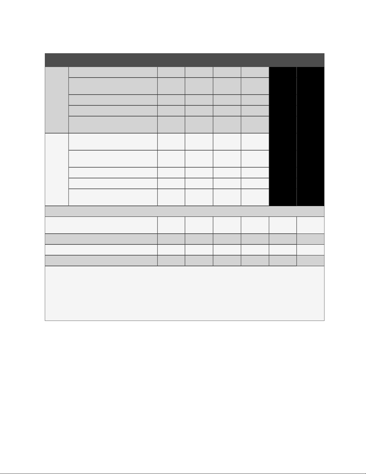
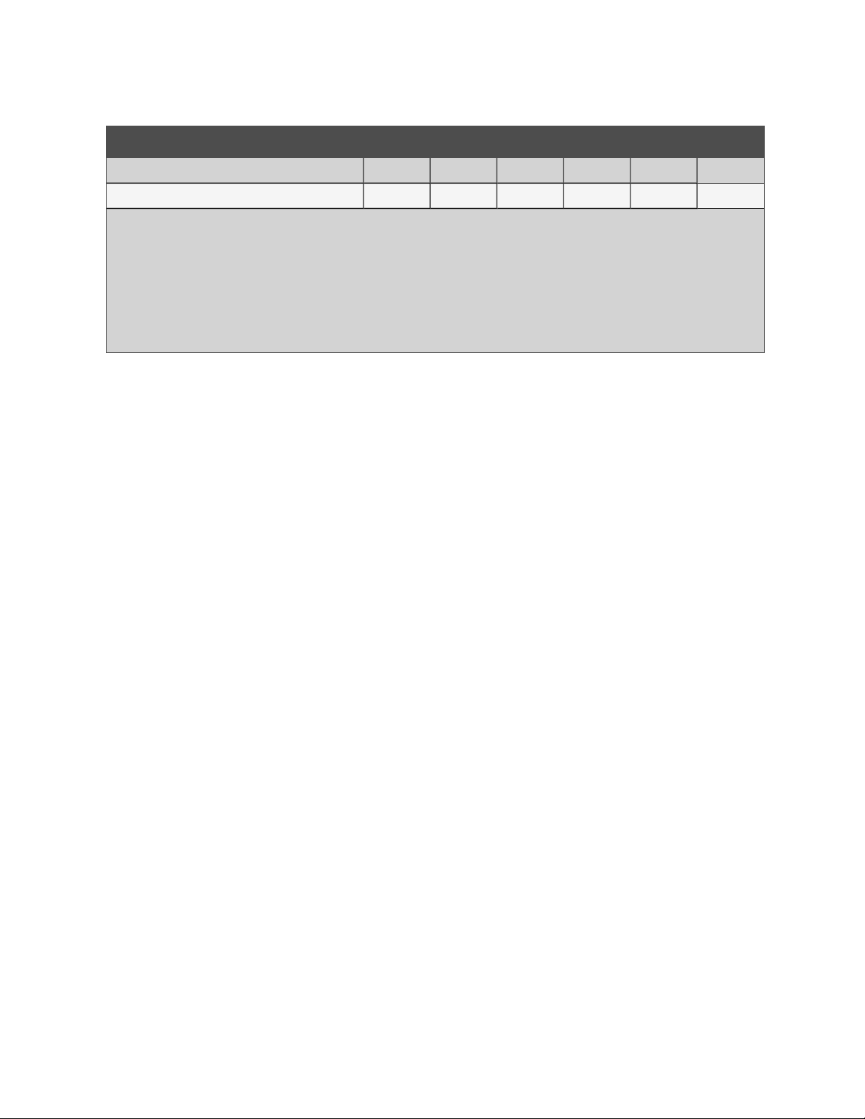
Table 2.1 Air Cooled Data for Downflow with EC Fan(s), 60 Hz Models (continued)
Model Size - Downflow Configuration DS035 DS042 DS053 DS070 DS077 DS105
Standard Fan Motor, hp (kW) 3.75 (2.8) 3.75 (2.8) 4.15 (3.1) 4.15 (3.1) 4.15 (3.1) 3.6 (2.7)
Number of Fans 1 1 2 2 2 3
External Static Pressure, in. w.g. (Pa) 0.2 (50)
1. Certified in accordance with the AHRI Datacom Cooling Certification Program at AHRI Standard 1360 (I-P) Standard Rating Conditions. Certified units
may be found in the AHRI Directory at www.ahridirectory.org.
2. Certified in accordance wit h the AHRI Standard 127-2007 Standard Rating Conditions. Certified units may be found in the Compliance Certification
Database at www.regulations.doe.gov.
2a. Performance data derived from Return ACFM required to be listed in Compliance Certification Database. (DS077 = 10,000),
3. Some options or combinations of options may result in reduced air flow. Consult factory for recommendations.
4. Net capacity data has fan motor heat factored in for all ratings.
5. Consult factory for alternate performance outputs. Performance data generated in LRSUpdate Version 06-22-2022.
6. See 2.4 on page37 for Optional Dual Cool Performance.
1,2
0.2 (50)
1,2
0.2 (50)
1,2
0.2 (50)
1,2
0.2 (50)
1,2
0.2 (50)
1,2
10
2 System Data
Proprietary and Confidential ©2023 Vertiv Group Corp.
Page 15
Vertiv™ Liebert® DS System Design Catalog
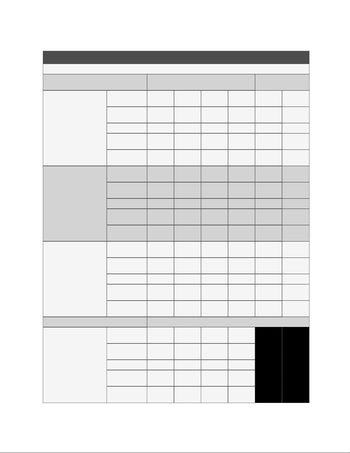
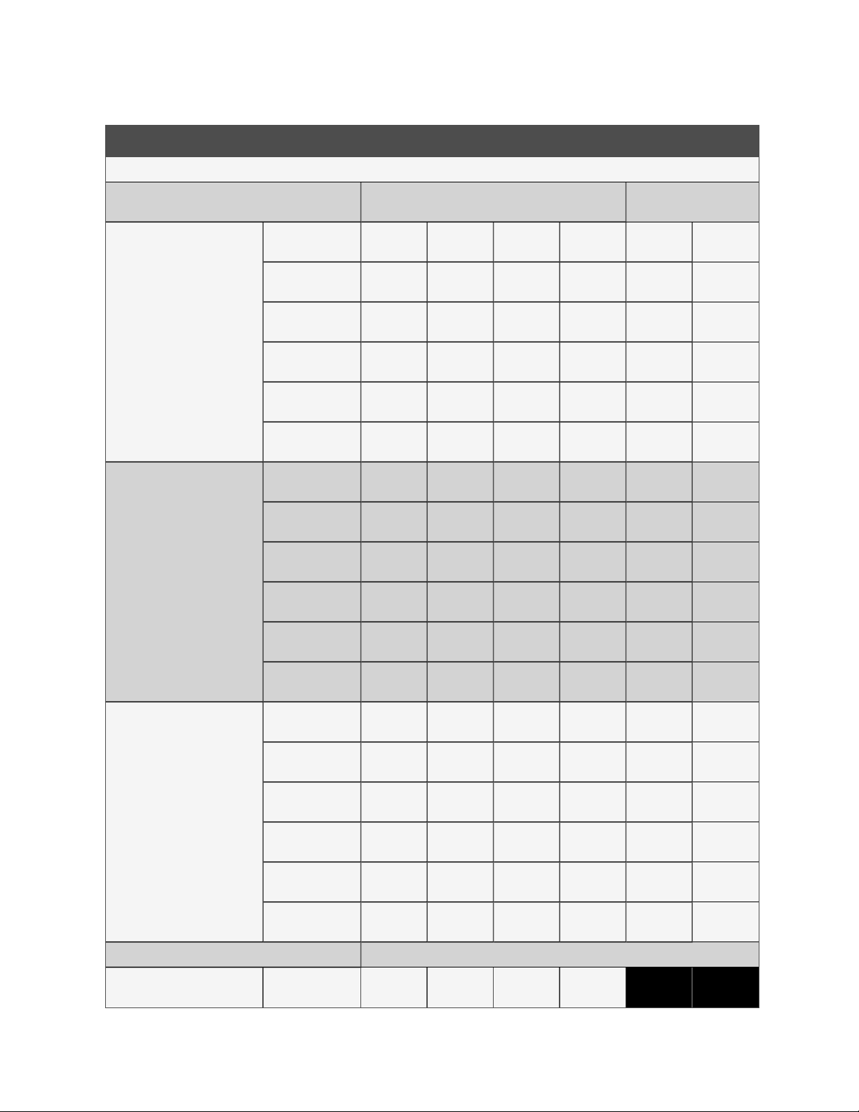
Table 2.2 Air Cooled Data for Upflow with EC Fan(s), 60 Hz Models
Model Size - Upflow Configuration VS035 VS042 VS053 VS070 VS077 VS105
Liebert® DX Evaporator - Net Capacity Data at 95°F (35°C) Outdoor Ambient
Compressor Type Digital Scroll
Microchannel Liebert® MC Match-up at 95°F (35°C)
Outdoor Ambient
Total, kW (BTUH)
85°F DB1, 64.4°F WB, 52°F DP,
32%RH (29.4°C DB, 18°C WB)
Sensible, kW
(BTUH)
MCS056 MCM080 MCS056 MCM080 MCL110 MCM160
37.6
(128,000)
37.4
(128,000)
43.3
(148,000)
43.0
(147,000)
External Static
Pressure, in.w.g.
0.41(100) 0.41(100) 0.41(100)
(Pa)
80°F DB, 62.7°F WB, 52°F DP,
38%RH (26.7°C DB, 17.1°C WB)
Total, kW (BTUH)
Sensible, kW
(BTUH)
35.8
(122,000)
34.2
(117,000)
41.3
(141,000)
39.2
(134,000)
External Static
Pressure, in.w.g.
0.5 (125) 0.5 (125) 0.5 (125) 0.5 (125) 0.5 (125) 0.5 (125)
(Pa)
75°F DB2, 61°F WB, 52°F DP,
44%RH (23.9°C DB, 16.1°C WB)
Total, kW (BTUH)
Sensible, kW
(BTUH)
33.8
(115,000)
29.9
(102,000)
39.1
(133,000)
34.3
(117,000)
External Static
Pressure, in.w.g.
1.02(250) 1.02(250) 1.02(250) 1.02(250) 1.02(250) 1.02(250)
(Pa)
57.9
(197,600)
57.9
(197,600)
54.8
(187,000)
53.5
(182,500)
51.5
(175,700)
47.3
(161,400)
71.6
(244,300)
71.0
(242,300)
1
0.5
(125)
68.5
(233,700)
65.3
(222,800)
64.9
(221,400)
57.4
(195,900)
Semi-hermetic (Four Step
Cooling)
81.2
(277,100)
79.8
(272,300)
0.5
(125)
77.5
(264,400)
72.9
(248,700)
73.3
(250,100)
62.8
(214,300)
1
2a
2a
102.0
(348,000)
97.3
(332,000)
0.5
(125)
97.9
(334,000)
88.6
(302,300)
93.0
(317,300)
76.7
(261,700)
1
2a
2a
2 System Data
Compressor Type Scroll (Two Step Cooling)
Microchannel Liebert® MC Match-up at 95°F (35°C)
Outdoor Ambient
Total, kW (BTUH)
85°F DB1, 64.4°F WB, 52°F DP,
32%RH (29.4°C DB, 18°C WB)
Sensible, kW
(BTUH)
MCS056 MCS056 MCS056 MCM080 MCL110 MCM160
37.8
(129,000)
37.5
(128,000)
41.6
(142,000)
41.5
(142,000)
59.0
(201,300)
59.0
(201,300)
73.4
(250,500)
72.3
(246,700)
External Static
Pressure, in.w.g.
0.41(100) 0.41(100) 0.41(100) 0.51(125) 0.51(125) 0.51(125)
(Pa)
80°F DB, 62.7°F WB, 52°F DP,
38%RH (26.7°C DB, 17.1°C WB)
Total, kW (BTUH)
Sensible, kW
(BTUH)
External Static
Pressure, in.w.g.
(Pa)
36.1
(123,000)
34.2
(117,000)
0.5
(125)
39.6
(135,000)
38.2
(130,000)
0.5
(125)
56.0
(191,100)
54.7
(186,600)
0.5
(125)
70.3
(239,900)
66.3
(226,200)
0.5
(125)
Proprietary and Confidential ©2023 Vertiv Group Corp.
83.3
(284,200)
81.3
(277,400)
79.8
(272,300)
74.1
(252,800)
0.5
(125)
102.0
(348,000)
97.5
(332,700)
98.4
(335,800)
88.8
(303,000)
0.5
(125)
11
Page 16
Vertiv™ Liebert® DS System Design Catalog
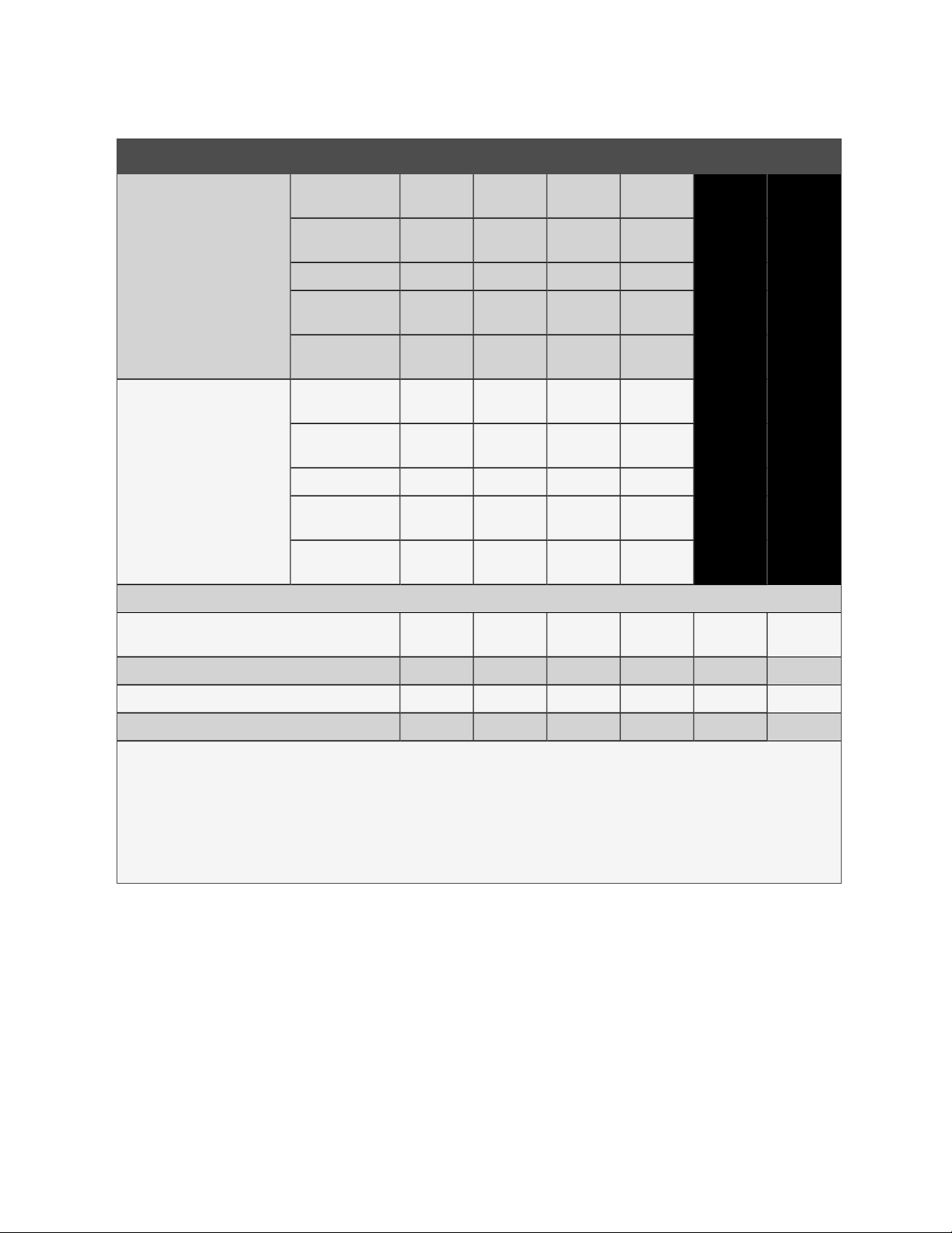
Table 2.2 Air Cooled Data for Upflow with EC Fan(s), 60 Hz Models (continued)
Model Size - Upflow Configuration VS035 VS042 VS053 VS070 VS077 VS105
75°F DB2, 61°F WB, 52°F DP,
44%RH (23.9°C DB, 16.1°C WB)
Total, kW (BTUH)
Sensible, kW
(BTUH)
34.2
(117,000)
30.0
(102,000)
37.4
(128,000)
33.4
(114,000)
52.8
(180,200)
48.4
(165,100)
66.8
(227,900)
58.3
(198,900)
75.9
(259,000)
64.0
(218,400)
2a
2a
93.6
(319,400)
77.0
(262,700)
External Static
Pressure, in.w.g.
1.02(250) 1.02(250) 1.02(250) 1.02(250) 1.02(250) 1.02(250)
(Pa)
FAN SECTION - EC Up
Return Air Volume, ACFM (ACMH)
5,200
(8,835)
6,200
(10,534)
8,000
(13,592)
9,600
(16,310)
11,000
(18,689)
13,700
(23,276)
Standard Fan Motor, hp (kW) 3.75 (2.8) 3.75 (2.8) 4.15 (3.1) 4.15 (3.1) 4.15 (3.1) 3.6 (2.7)
Number of Fans 1 1 2 2 2 3
1. Certified in accordance with the AHRI Datacom Cooling Certification Program at AHRI Standard 1360 (I-P) Standard Rating Conditions. Certified units
may be found in the AHRI Directory at www.ahridirectory.org.
2. Certified in accordance with the ASHRAE Standard 127-2007 Standard Rating Conditions. Certified units may be found in the Compliance Certification
Database at www.regulations.doe.gov.
2a. Performance data derived from Return ACFM required to be listed in Compliance Certification Database. (VS077=10,400; VS105=13,200)
3. Some options or combinations of options may result in reduced air flow. Consult factory for recommendations.
4. Net capacity data has fan motor heat factored in for all ratings.
5. Consult factory for alternate performance outputs. Performance data generated in LRS Update Version 06-22-2022.
6. See Table 2.14 on page39 for Optional Dual Cool Performance.
2a
2a
12
2 System Data
Proprietary and Confidential ©2023 Vertiv Group Corp.
Page 17
Vertiv™ Liebert® DS System Design Catalog
Table 2.3 Air Cooled Data for Upflow with Centrifugal (Forward Curved) Fan(s), 60 Hz Models
Model Size - Upflow Configuration VS035 VS042 VS053 VS070 VS077 VS105
Liebert® DX Evaporator - Net Capacity Data at 95°F (35°C) Outdoor Ambient
Compressor Type Digital Scroll
Microchannel Liebert® MC Match-up at 95°F (35°C)
Outdoor Ambient
Total, kW (BTUH)
85°F DB1, 64.4°F WB, 52°F DP,
32%RH (29.4°C DB, 18°C WB)
Sensible, kW
(BTUH)
MCS056 MCS056 MCM080 MCL110 MCM160
37.1
(127,000)
37.1
(127,000)
External Static
Pressure, in.w.g.
0.41(100) 0.41(100) 0.51(125) 0.51(125) 0.51(125)
(Pa)
35.2
(120,000)
34.0
(116,000)
0.5
(125)
33.3
(114,000)
29.2
(100,000)
2a
2a
80°F DB, 62.7°F WB, 52°F DP,
38%RH (26.7°C DB, 17.1°C WB)
75°F DB2, 61°F WB, 52°F DP,
44%RH (23.9°C DB, 16.1°C WB)
Total, kW (BTUH)
Sensible, kW
(BTUH)
External Static
Pressure, in.w.g.
(Pa)
Total, kW (BTUH)
Sensible, kW
(BTUH)
External Static
Pressure, in.w.g.
1.02(250) 1.02(250) 1.02(250) 1.02(250) 1.02(250)
(Pa)
Semi-hermetic (Four Step
Cooling)
57.8
(197,200)
57.8
(197,200)
54.7
(186,600)
53.4
(182,200)
71.4
(243,600)
70.7
(241,200)
68.2
(232,700)
65.0
(221,800)
80.8
(275,700)
79.4
(270,900)
77.1
(263,100)
72.4
(247,000)
102.0
(348,000)
98.3
(335,400)
97.4
(332,300)
89.7
(306,100)
0.5 (125) 0.5 (125) 0.5 (125) 0.5 (125)
51.4
(175,400)
47.2
(161,100)
64.6
(220,400)
57.1
(194,800)
72.9
(248,700)
62.1
(211,900)
2a
(314,900)
78.3
2a
(267,200)
92.3
2 System Data
Compressor Type Scroll (Two Step Cooling)
Microchannel Liebert® MC Match-up at 95°F (35°C)
Outdoor Ambient
Total, kW (BTUH)
85°F DB1, 64.4°F WB, 52°F DP,
32%RH (29.4°C DB, 18°C WB)
Sensible, kW
(BTUH)
MCS056 MCM080 MCS056 MCM080 MCM160 MCM160
37.3
(127,000)
37.3
(127,000)
41.8
(143,000)
41.8
(143,000)
58.9
(201,000)
58.9
(201,000)
73.1
(249,400)
72.0
(245,700)
External Static
Pressure, in.w.g.
0.41(100) 0.41(100) 0.41(100) 0.51(125) 0.51(125) 0.51(125)
(Pa)
Compressor Type Scroll (Two Step Cooling)
80°F DB, 62.7°F WB, 52°F DP,
38%RH (26.7°C DB, 17.1°C WB)
Total, kW (BTUH)
Sensible, kW
(BTUH)
External Static
35.5
(121,000)
34.1
(116,000)
0.5 (125) 0.5 (125) 0.5 (125) 0.5 (125) 0.5 (125) 0.5 (125)
39.6
(135,000)
38.3
(131,000)
55.9
(190,700)
54.5
(186,000)
70.1
(239,200)
66.1
(225,500)
Proprietary and Confidential ©2023 Vertiv Group Corp.
83.6
(285,300)
81.3
(277,400)
80.2
(273,700)
74.0
(252,500)
102.0
(348,000)
98.5
(336,100)
97.9
(334,000)
89.9
(306,800)
13
Page 18
Vertiv™ Liebert® DS System Design Catalog
Table 2.3 Air Cooled Data for Upflow with Centrifugal (Forward Curved) Fan(s), 60 Hz Models (continued)
Model Size - Upflow Configuration VS035 VS042 VS053 VS070 VS077 VS105
Pressure, in.w.g.
(Pa)
75°F DB2, 61°F WB, 52°F DP,
44%RH (23.9°C DB, 16.1°C WB)
Total, kW (BTUH)
Sensible, kW
(BTUH)
33.5
(114,000)
29.8
(102,000)
2a
2a
37.8
(129,000)
32.8
(112,000)
2a
(179,500)
48.2
2a
(164,500)
52.6
66.5
(226,900)
58.1
(198,200)
76.3
(260,300)
63.6
(217,000)
2a
2a
92.9
(317,000)
78.5
(267,900)
External Static
Pressure, in.w.g.
1.02(250) 1.02(250) 1.02(250) 1.02(250) 1.02(250) 1.02(250)
(Pa)
FAN SECTION - Centrifugal (Forward Curved)
Return Air Volume, ACFM (ACMH)
5,500
(9,345)
6,600
(11,213)
8,000
(13,592)
9,600
(16,310)
11,000
(18,689)
14,600
(24,805)
Standard Fan Motor, hp (kW) 3.0 (2.2) 5.0 (3.7) 3.0 (2.2) 5.0 (3.7) 7.5 (5.6) 10.0 (7.5)
Optional Fan Motor, hp (kW) 5.0 (3.7) 7.5 (5.6) 5.0 (3.7) 7.5 (5.6) 10.0 (7.5) 15.0 (11.2)
Number of Fans 1 1 2 2 2 3
1. Certified in accordance with the AHRI Datacom Cooling Certification Program at AHRI Standard 1360 (I-P) Standard Rating Conditions. Certified units
may be found in the AHRI Directory at www.ahridirectory.org.
2. Certified in accordance with the ASHRAE Standard 127-2007 Standard Rating Conditions. Certified units may be found in the Compliance Certification
Database at www.regulations.doe.gov.
2a. Performance data derived from Return ACFM required to be listed in Compliance Certification Database. (VS035=5,100; VS042=6,000; VS077=10,200)
3. Some options or combinations of options may result in reduced air flow. Consult factory for recommendations.
4. Net capacity data has fan motor heat factored in for all ratings.
5. Consult factory for alternate performance outputs. Performance data generated in LRS Update Version 06-22-2022.
6. See Table 2.15 on page41 for Optional Dual Cool Performance.
14
2 System Data
Proprietary and Confidential ©2023 Vertiv Group Corp.
Page 19

Vertiv™ Liebert® DS System Design Catalog
2.2 Water Cooled Capacity and Performance Data
Table 2.4 Water Cooled Data for Downflow with EC Fan(s), 60 Hz Models
Model Size - Downflow DS035 DS042 DS053 DS070 DS077 DS105
Liebert® DX Evaporator - Net Capacity Data with 83°F Entering and 95°F Leaving Fresh Water Temperatures
Compressor Type Digital Scroll
85°F DB1,
64.4°F
WB, 52°F
DP,
32%RH
(29.4°C
DB, 18°C
WB)
80°F DB,
62.7°F WB,
52°F DP,
38%RH
(26.7°C
DB, 17.1°C
WB)
Total, kW (BTUH)
Sensible, kW (BTUH)
Flow Rate, GPM (lps) 31.1 (2.0) 35.0 (2.2) 46.8 (2.9) 58.3 (3.7) 64.3 (4.1.) 78.9 (5.0)
Unit Pressure Drop, ft of Water (kPa) 10.9 (32.6) 13.6 (40.7) 13.1 (39.2) 19.9 (59.5) 23.9(71.5) 31.2 (93.3)
Heat Rejection, kW (BTUH)
Total, kW (BTU
Sensible, kW (BTUH)
Flow Rate, GPM (lps) 29.8 (1.9) 33.5 (2.1) 45 (2.8) 56.3 (3.5) 62.1 (3.9) 76.1 (4.8)
Unit Pressure Drop, ft of Water (kPa) 10.0 (29.9) 12.5 (37.4) 12.2 (36.5) 18.6 (55.6) 22.3 (66.7) 29.2 (87.3)
Heat Rejection, kW (BTUH)
42.5
(145,000)
42.4
(145,000)
54.5
(186,000)
40.3
(138,000)
38.7
(132,000)
52.2
(178,000)
47.6
(162,000)
47.5
(162,000)
61.2
(209,000)
45.1
(154,000)
43.7
(149,000)
58.6
(200,000)
66.5
(227,000)
64.9
(221,000)
81.9
(279,000)
63.3
(216,000)
59.3
(202,000)
78.8
(269,000)
1
(275,000)
(265,000)
(349,000)
(264,000)
(241,000)
(336,000)
80.7
77.7
102.2
77.3
70.7
98.6
Semi-hermetic (Four Step
Cooling)
86.9
(297,000)
84.3
(288,000)
112.8
(385,000)
83.0
(283,000)
76.7
(262,000)
108.7
(371,000)
106.5
(363,000)
102.6
(350,000)
138.2
472,000)
101.8
(347,000)
93.9
(320,000)
133.4
(455,000)
Total, kW (BTUH)
75°F DB,
61°F WB,
52°F DP,
44%RH
(23.9°C
DB, 16.1°C
WB)
Compressor Type Scroll (Two Step Cooling)
85°F DB1,
64.4°F
WB, 52°F
DP,
32%RH
(29.4°C
DB, 18°C
WB)
80°F DB,
Sensible, kW (BTUH)
Flow Rate, GPM (lps) 28.6 (1.8) 32.2 (2.0) 43.3 (2.7) 54.4 (3.4) 59.9 (3.8) 73.5 (4.6)
Unit Pressure Drop, ft of Water (kPa) 9.3 (27.8) 11.6 (34.7) 11.3 (33.8) 17.4 (52) 20.9 (62.5) 27.3 (81.6)
Heat Rejection, kW (BTUH)
Total, kW (BTUH)
Sensible, kW (BTUH)
Flow Rate, GPM (lps) 29.6 (1.9) 34.4 (2.2) 46.8 (2.9) 58.7 (3.7)
Unit Pressure Drop, ft of Water (kPa) 9.9 (29.6) 13.1 (39.2) 13.1 (39.2) 20.2 (60.4)
Heat Rejection, kW (BTUH)
Total, kW (BTUH)
38.4
(131,000)
34.5
(118,000)
50.1
(171,000)
41.1
(140,000)
41.1
(140,000)
51.8
(177,000)
39.0 45.4 63.6 78.0
43.0
(147,000)
38.9
(133,000)
56.4
(192,000)
47.8
(163,000)
47.7
(163,000)
60.2
(205,000)
60.3
(206,000)
52.9
(181,000)
75.8
(259,000)
66.5
(227,000)
65.0
(222,000)
82.0
(280,000)
74.1
(253,000_
63.0
(215,000)
95.3
(325,000)
81.3
(277,000)
78.0
(266,000)
102.8
(351,000)
79.4
(271,000)
68.2
(233,000)
105.0
(358,000)
97.5
(333,000)
84.1
(287,000)
128.7
(439,000)
2 System Data
15
Proprietary and Confidential ©2023 Vertiv Group Corp.
Page 20
Vertiv™ Liebert® DS System Design Catalog
Table 2.4 Water Cooled Data for Downflow with EC Fan(s), 60 Hz Models (continued)
Model Size - Downflow DS035 DS042 DS053 DS070 DS077 DS105
(133,000) (155,000) (217,000) (266,000)
62.7°F WB,
52°F DP,
38%RH
(26.7°C
DB, 17.1°C
Sensible, kW (BTUH)
37.9
(129,000)
Flow Rate, GPM (lps) 28.3 (1.8) 33.0 (2.1) 45.2 (2.8) 56.8 (3.6)
Unit Pressure Drop, ft of Water (kPa) 9.1 (27.2) 12.1 (36.2) 12.3 (36.8) 18.9 (56.5)
43.9
(150,000)
59.5
(203,000)
71.1
(243,000)
WB)
Heat Rejection, kW (BTUH)
Total, kW (BTUH)
49.6
(169,000)
37.2
(127,000)
57.8
(197,000)
43.4
(148,000)
79.2
(270,000)
60.9
(208,000)
99.5
(340,000)
75.0
(256,000)
75°F DB,
61°F WB,
52°F DP,
44%RH
(23.9°C
DB, 16.1°C
Sensible, kW (BTUH)
33.8
(115,000)
Flow Rate, GPM (lps) 27.3 (1.7) 31.8 (2.0) 43.7 (2.8) 55.0 (3.5)
Unit Pressure Drop, ft of Water (kPa) 8.5 (25.4) 11.3 (33.8) 11.5 (34.4) 17.8 (53.2)
39.1
(133,000)
53.1
(181,000)
63.5
(217,000)
WB)
Heat Rejection, kW (BTUH)
47.8
(163,000)
55.8
(190,000)
76.5
(261,000)
96.4
(329,000)
FANSECTION- ECDown
Return Air Volume, ACFM (ACMH)
5,200
(8,835)
6,200
(10,534)
8,000
(13,592)
9,600
(16,310)
11,000
(18,689)
13,700
(23,276)
Standard Fan Motor, hp (kW) 3.75 (2.8) 3.75 (2.8) 4.15 (3.1) 4.15 (3.1) 4.15 (3.1) 3.6 (2.7)
Number of Fans 1 1 2 2 2 3
External Static Pressure, in.w.g. (Pa) 0.2 (50)
1,2
0.2 (50)
1,2
0.2 (50)
1,2
0.2 (50)
1,2
0.2 (50)
1,2
0.2 (50)
1,2
1. Certified in accordance with the AHRI Datacom Cooling Certification Program at AHRI Standard 1360 (1-P) Standard Rating Conditions. Certified units
may be found in the AHRI Directory at www.ahridirectorv.org.
2. Certified in accordance with the ASHRAE Standard 127-2007 Standard Rating Conditions. Certified units may be found in the Compliance Certification
Database at www.regulations.doe.gov.
3. Some options or combinations of options may result in reduced air flow. Consult factory for recommendations.
4. Net capacity data has fan motor heat factored in for all ratings.
5. Consult factory for alternate performance outputs. Performance data generated in LRS Update Version 06-22-2022.
6. See Table 2.15 on page41 for Optional Dual Cool Performance.
16
2 System Data
Proprietary and Confidential ©2023 Vertiv Group Corp.
Page 21
Vertiv™ Liebert® DS System Design Catalog
Table 2.5 Water Cooled Data for Downflow with EC Fan(s), 60 Hz Models
Model Size - Downflow DS035 DS042 DS053 DS070 DS077 DS105
Liebert® DX Evaporator - Net Capacity Data with 86°F Entering and 95°F Leaving Fresh Water Temperatures
Compressor Type Digital Scroll
85°F DB, 64.4°F WB, 52°F DP,
32%RH (29.4°C DB, 18°C WB)
80°F DB, 62.7°F WB, 52°F DP,
38%RH (26.7°C DB, 17.1°C WB)
Total, kW (BTUH)
Sensible, kW
(BTUH)
42.2
(144,000)
42.1
(144,000)
Flow Rate, GPM (lps) 41.4 (2.6) 46.5 (2.9) 62.2 (3.9) 77.7 (4.9) 82.5 (5.2) 101.3 (6.4)
Unit Pressure Drop,
ft of Water (kPa)
Heat Rejection, kW
(BTUH)
Total, kW (BTUH)
Sensible, kW
(BTUH)
18.8 (56.2) 23.4 (70.0) 22.6 (67.6) 34.5 (103.2) 38.4 (114.8) 50.1 (149.8)
54.3
(185,000)
40.0
(136,000)
38.5
(131,000)
Flow Rate, GPM (lps) 39.6 (2.5) 44.5 (2.8) 59.8 (3.8) 74.9 (4.7) 85.6 (5.4) 104.9 (6.6)
Unit Pressure Drop,
ft of Water (kPa)
Heat Rejection, kW
(BTUH)
17.3 (51.7) 21.5 (64.3) 20.9 (62.5) 32.1 (96.0) 41.2 (123.2) 53.6 (160.3)
52.0
(177,000)
47.2
(161,000)
47.2
(161,000)
61.1
(208,000)
44.7
(153,000)
43.4
(148,000)
58.4
(199,000)
66.0
(225,000)
64.6
(220,000)
81.7
(279,000)
62.8
(214,000)
59.0
(201,000)
78.5
(268,000)
2
80.0
(273,000)
77.3
(264,000)
101.9
(348,000)
76.6
(261,000)
70.3
(240,000)
98.4
(336,000)
Semi-hermetic (Four Step
Cooling)
82.2
(280,000)
76.2
(260,000)
108.2
(369,000)
86.1
(294,000)
83.8
(286,000)
112.3
(383,000)
100.8
(344,000)
93.3
(318,000)
132.8
(453,000)
105.5
(360,000)
101.9
(348,000)
137.7
(470,000)
75°F DB2, 61°F WB, 52°F DP,
44%RH (23.9°C DB, 16.1"C WB)
Total, kW (BTUH)
Sensible, kW
(BTUH)
38.1
(130,000)
34.3
(117,000)
Flow Rate, GPM (lps) 38.1 (2.4) 42.8 (2.7) 57.6 (3.6) 72.4 (4.6) 79.6 (5.0) 97.7 (6.2)
Unit Pressure Drop,
ft of Water (kPa)
Heat Rejection, kW
(BTUH)
16.0 (47.8) 19.9 (59.5) 19.5 (58.3) 30.1 (90.0) 35.8 (107.0) 46.7 (139.6)
50.0
(171,000)
42.6
(145,000)
38.7
(132,000)
56.2
(192,000)
59.8
(204,000)
52.6
(179,000)
75.6
(258,000)
73.4
(250,000)
62.7
(214,000)
95.1
(324,000)
Compressor Type Scroll (Two Step Cooling)
85°F DB, 64.4°F WB, 52°F DP,
32%RH (29.4°C DB, 18°C WB)
Total, kW (BTUH)
Sensible, kW
(BTUH)
40.9
(140,000)
40.9
(140,000)
Flow Rate, GPM (lps) 39.4 (2.5) 45.7 (2.9) 62.3 (3.9) 78.1 (4.9)
Unit Pressure Drop,
ft of Water (kPa)
Heat Rejection, kW
(BTUH)
17.1 (51.1) 22.6 (67.6) 22.7 (67.9) 34.9 (104.4)
51.7
(176,000)
47.4
(162,000
47.4
(162,000)
60.0
(205,000)
66.0
(225,000)
64.6
(220,000)
81.8
(279,000)
80.6
(275,000)
77.6
(265,000)
102.5
(350,000)
78.6
(268,000)
67.8
(231,000)
104.5
(357,000)
96.4
(329,000)
83.6
(285,000)
128.2
(437,000)
2 System Data
17
Proprietary and Confidential ©2023 Vertiv Group Corp.
Page 22
Vertiv™ Liebert® DS System Design Catalog
Table 2.5 Water Cooled Data for Downflow with EC Fan(s), 60 Hz Models (continued)
Model Size - Downflow DS035 DS042 DS053 DS070 DS077 DS105
80°F DB, 62.7°F WB, 52°F DP,
38%RH (26.7°C DB, 17.1°C WB)
75°F DB2, 61°F WB, 52°F DP,
44%RH (23.9°C DB, 16.1"C WB)
FANSECTION - EC Down
Return Air Volume, ACFM (ACMH)
Total, kW (BTUH)
Sensible, kW
(BTUH)
38.8
(132,000)
37.8
(129,000)
45.0
(154,000)
43.6
(149,000)
63.1
(215,000)
59.2
(202,000)
77.4
(264,000)
70.7
(241,000)
Flow Rate, GPM (lps) 37.7 (2.4) 43.9 (2.8) 60.1 (3.8) 75.6 (4.8)
Unit Pressure Drop,
ft of Water (kPa)
Heat Rejection, kW
(BTUH)
Total, kW (BTUH)
Sensible, kW
(BTUH)
15.7 (46.9) 20.9 (62.5) 21.2 (63.4) 32.7 (97.8)
49.5
(169,000)
36.9
(126,000)
33.7
(115,000)
57.6
(197,000)
43.0
(147,000)
38.9
(133,000)
79.0
(270,000)
60.4
(206,000)
52.9
(181,000)
99.2
(338,000)
74.4
(254,000)
63.2
(216,000)
Flow Rate, GPM (lps) 36.3 (2.3) 42.4 (2.7) 58.1 (3.7) 73.2 (4.6)
Unit Pressure Drop,
ft of Water (kPa)
Heat Rejection, kW
(BTUH)
14.6 (43.7) 19.5 (58.3) 19.8 (59.2) 30.7 (91.8)
47.7
(163,000)
5,200
(8,835)
55.6
(190,000)
6,200
(10,534)
76.3
(260,000)
8,000
(13,592)
96.1
(328,000)
9,600
(16,310)
11,000
(18,689)
13,700
(23,276)
Standard Fan Motor, hp (kW) 3.75 (2.8) 3.75 (2.8) 4.15 (3.1) 4.15 (3.1) 4.15 (3.1) 3.6 (2.7)
Number of Fans 1 1 2 2 2 3
External Static Pressure, in.w.g. (Pa) 0.2 (50)
1,2
0.2 (50)
1,2
0.2 (50)
1,2
0.2 (50)
1,2
0.2 (50)
1,2
0.2 (50)
1. Certified in accordance with the AHRI Datacom Cooling Certification Program at AHRI Standard 1360 (I-P) Standard Rating Conditions. Certified units
may be found in the AHRI Directory at www.ahridirectory.org.
2. Certified in accordance with the ASHRAE Standard 127-2007 Standard Rating Conditions. Certified units may be found in the Compliance Certification
Database at www.regulations.doe.gov.
3. Some options or combinations of options may result in reduced air flow. Consult factory for recommendations.
4. Net capacity data has fan motor heat factored in for all ratings.
5. Consult factory for alternate performance outputs. Performance data generated in LRS Update Version 06-22-2022.
6. See Table 2.13 on page37 for Optional Dual Cool Performance.
1,2
18
2 System Data
Proprietary and Confidential ©2023 Vertiv Group Corp.
Page 23

Vertiv™ Liebert® DS System Design Catalog
Table 2.6 Water Cooled Data for Upflow with EC Fan(s) 60 Hz Models
Model Size - Upflow VS035 VS042 VS053 VS070 VS077 VS105
Liebert® DX Evaporator - Net Capacity Data with 83°F Entering and 95°F Leaving Fresh Water Temperatures
Compressor Type Digital Scroll
85°F DB1, 64.4°F WB, 52°F DP,
32%RH (29.4°C DB, 18°C WB)
80°F DB, 62.7°F WB, 52°F DP,
38%RH (26.7°C DB, 17.1°C WB)
Total, kW (BTUH)
Sensible, kW
(BTUH)
Flow Rate, GPM
(lps)
Unit Pressure Drop,
ft of Water (kPa)
Heat Rejection, kW
(BTUH)
External Static
Pressure, in.w.g. (Pa)
Total, kW (BTUH)
Sensible, kW
(BTUH)
Flow Rate, GPM
(lps)
Unit Pressure Drop,
ft of Water (kPa)
43.0
(147,000)
43.0
(147,000)
31.6 (2.0) 35.5 (2.2) 46.7 (2.9) 58.3 (3.7) 64.3 (4.1) 78.1 (4.9)
11.2 (33.5) 14.0 (41.9) 13.1 (39.2) 19.9 (59.5) 23.9 (71.5) 30.7 (91.8)
55.3
(189,000)
0.41(100) 0.41(100) 0.41(100) 0.51(125) 0.51(125) 0.51(125)
40.7
(139,000)
39.1
(133,000)
30.2 (1.9) 34.0 (2.1) 44.9 (2.8) 56.3 (3.5) 62.0 (3.9) 75.4 (4.8)
10.3 (30.8) 12.8 (38.3) 12.1 (36.2) 18.6 (55.6) 22.3 (66.7) 28.6 (85.5)
48.3
(165,000)
48.3
(165,000)
62.2
(212,000)
45.6
(156,000)
44.3
(151,000)
66.2
(226,000)
64.6
(220,000)
81.9
(279,000)
62.8
(214,000)
58.8
(201,000)
1
80.3
(274,000)
77.2
(263,000)
102.1
(348,000)
76.9
(262,000)
70.2
(240,000)
Semi-hermetic (Four Step
Cooling)
86.6
(295,000)
83.9
(286,000)
112.7
(385,000)
82.7
(282,000)
76.2
(260,000)
104.9
(358,000)
100.9
(344,000)
136.9
(467,000)
100.3
(342,000)
92.3
(315,000)
75°F DB, 61°F WB, 52°F DP,
44%RH (23.9°C DB, 16.1°C WB)
Heat Rejection, kW
(BTUH)
External Static
Pressure, in.w.g. (Pa)
Total, kW (BTUH)
Sensible, kW
(BTUH)
Flow Rate, GPM
(lps)
Unit Pressure Drop,
ft of Water (kPa)
Heat Rejection, kW
(BTUH)
External Static
Pressure, in.w.g. (Pa)
52.8
(180,000)
59.5
(203,000)
78.7
(269,000)
98.6
(336,000)
0.5 (125) 0.5 (125) 0.5 (125) 0.5 (125) 0.5 (125) 0.5 (125)
38.2
(130,000)
34.2
(117,000)
42.9
(146,000)
38.8
(132,000)
59.1
(202,000)
51.6
(176,000)
72.7
(248,000)
61.6
(210,000)
29.0 (1.8) 32.6 (2.1) 43.3 (2.7) 54.4 (3.4) 59.4 (3.7)
9.5 (28.4) 11.9 (35.6) 11.3 (33.8) 17.4 (52.0) 21.0 (62.8)2a27.0 (80.7)
50.8
(173,000)
57.2
(195,000)
75.8
(259,000)
95.3
(325,000)
1.0 (250) 1.0 (250) 1.0 (250) 1.0 (250) 1.0 (250) 1.0 (250)
Compressor Type Scroll (Two Step Cooling)
85°F DB1, 64.4°F WB, 52°F DP,
32%RH (29.4°C DB, 18°C WB)
Total, kW (BTUH)
41.6
(142,000)
48.5
(165,000)
66.3
(226,000)
80.9
(276,000)
108.6
(371,000)
78.0
(266,000)
65.6
(224,000)
104.1
(355,000)
2a
2a
2a
2a
132.1
(451,000)
94.6
(323,000)
80.3
(274,000)
72.4 (4.6)
126.8
(433,000)
2a
2a
2a
2a
2a
2 System Data
19
Proprietary and Confidential ©2023 Vertiv Group Corp.
Page 24
Vertiv™ Liebert® DS System Design Catalog
Table 2.6 Water Cooled Data for Upflow with EC Fan(s) 60 Hz Models (continued)
Model Size - Upflow VS035 VS042 VS053 VS070 VS077 VS105
80°F DB, 62.7°F WB, 52°F DP,
38%RH (26.7°C DB, 17.1°C WB)
Sensible, kW
(BTUH)
Flow Rate, GPM
(lps)
Unit Pressure Drop,
ft of Water (kPa)
Heat Rejection, kW
(BTUH)
External Static
Pressure, in.w.g. (Pa)
Total, kW (BTUH)
Sensible, kW
(BTUH)
Flow Rate, GPM
(lps)
Unit Pressure Drop,
ft of Water (kPa)
Heat Rejection, kW
(BTUH)
External Static
Pressure, in.w.g. (Pa)
41.6
(142,000)
30.0 (1.9) 34.9 (2.2) 46.8 (2.9) 58.7 (3.7)
10.1 (30.2) 13.5 (40.4) 13.1 (39.2) 20.1 (60.1)
52.5
(179,000)
0.41(100) 0.41(100) 0.41(100) 0.51(125)
39.3
(134,000)
38.3
(131,000)
28.7 (1.8) 33.4 (2.1) 45.2 (2.8) 56.8 (3.6)
9.3 (27.8) 12.4 (37.1) 12.3 (36.8) 18.9 (56.5)
50.2
(171,000)
0.5 (125) 0.5 (125) 0.5 (125) 0.5 (125)
48.5
(165,000)
61.1
(208,000)
45.9
(157,000)
44.5
(152,000)
58.6
(200,000)
64.7
(221,000)
82.0
(280,000)
63.2
(216,000)
59.0
(201,000)
79.1
(270,000)
77.5
(264,000)
102.8
(351,000)
77.6
(265,000)
70.6
(241,000)
99.5
(340,000)
75°F DB, 61°F WB, 52°F DP,
44%RH (23.9°C DB, 16.1°C WB)
FAN SECTION - EC Up
Return Air Volume, ACFM (ACMH)
Total, kW (BTUH)
Sensible, kW
(BTUH)
Flow Rate, GPM
(lps)
Unit Pressure Drop,
ft of Water (kPa)
Heat Rejection, kW
(BTUH)
External Static
Pressure, in.w.g. (Pa)
36.9
(126,000)
33.6
(115,000)
27.6 (1.7) 32.2 (2.0) 43.7 (2.8) 55.0 (3.5)
8.6 (25.7) 11.6 (34.7) 11.5 (34.4) 17.8 (53.2)
48.3
(165,000)
1.0 (250) 1.0 (250) 1.0 (250) 1.0 (250)
5,200
(8,835)
43.2
(147,000)
39.0
(133,000)
56.5
(193,000)
6,200
(10,534)
59.7
(204,000)
51.9
(177,000)
76.5
(261,000)
8,000
(13,592)
73.7
(251,000)
62.0
(212,000)
96.4
(329,000)
9,600
(16,310)
11,000
(18,689)
13,700
(23,276)
20
2 System Data
Proprietary and Confidential ©2023 Vertiv Group Corp.
Page 25

Vertiv™ Liebert® DS System Design Catalog
Table 2.6 Water Cooled Data for Upflow with EC Fan(s) 60 Hz Models (continued)
Model Size - Upflow VS035 VS042 VS053 VS070 VS077 VS105
Standard Fan Motor, hp (kW) 3.75 (2.8) 3.75 (2.8) 4.15 (3.1) 4.15 (3.1) 4.15 (3.1) 3.6 (2.7)
Number of Fans 1 1 2 2 2 3
1. Certified in accordance with the AHRI Datacom Cooling Certification Program at AHRI Standard 1360 (I-P) Standard Rating Conditions. Certified units
may be found in the AHRI Directory at www.ahridirectory.org.
2. Certified in accordance with the ASHRAE Standard 127-2007 Standard Rating Conditions. Certified units may be found in the Compliance Certification
Database at www.regulations.doe.gov.
2a. Performance data derived from Return ACFM required to be listed in Compliance Certification Database (VS077=10,400; VS105=13,200).
3. Some options or combinations of options may result in reduced air flow. Consult factory for recommendations.
4. Net capacity data has fan motor heat factored in for all ratings.
5. Consult factory for alternate performance outputs. Performance data generated in LRS Update Version 06-22-2022.
6. See Table 2.14 on page39 for Optional Dual Cool Performance.
2 System Data
21
Proprietary and Confidential ©2023 Vertiv Group Corp.
Page 26
Vertiv™ Liebert® DS System Design Catalog
Table 2.7 Water Cooled Data for Upflow with EC Fan(s), 60 Hz Models
Model Size - Upflow VS035 VS042 VS053 VS070 VS077 VS105
Liebert® DX Evaporator - Net Capacity Data with 86°F Entering and 95°F Leaving Fresh Water Temperatures
Compressor Type Digital Scroll
85°F DB, 64.4°F WB, 52°F DP,
32%RH (29.4°C DB, 18°C WB)
8O°F DB, 62.7°F WB, 52°F DP,
38%RH (26.7°C DB, 17.1°C WB)
Total, kW (BTUH)
Sensible, kW
(BTUH)
Flow Rate, GPM
(lps)
Unit Pressure Drop,
ft of Water (kPa)
Heat Rejection, kW
(BTUH)
External Static
Pressure, in.w.g. (Pa)
Total, kW (BTUH)
Sensible, kW
(BTUH)
Flow Rate, GPM
(lps)
Unit Pressure Drop,
ft of Water (kPa)
42.7
(146,000)
42.7
(146,000)
42.0 (2.6) 47.3 (3.0) 62.2 (3.9) 77.6 (4.9) 85.5 (5.4) 1103.9 (6.5)
19.3 (57.7) 24.2 (72.4) 22.6 (67.6) 34.4 (102.9) 41.2 (123.2) 52.6 (157.3)
55.1
(188,000)
0.4 (100) 0.4 (100) 0.4 (100) 0.5 (125) 0.5 (125) 0.5 (125)
40.4
(138,000)
38.9
(133,000)
40.1 (2.5) 45.1 (2.8) 59.7 (3.8) 74.9 (4.7) 82.4 (5.2) 100.2 (6.3)
17.7 (52.9) 22.1 (66.1) 20.9 (62.5) 32.1 (96.0) 38.3 (114.5) 49.1 (146.8)
48.0
(164,000)
48.0
(164,000)
62.0
(212,000)
45.2
(154,000)
44.1
(150,000)
65.7
(224,000)
64.3
(219,000)
81.6
(278,000)
62.3
(213,000)
58.5
(200,000)
2
79.6
(272,000)
76.8
(262,000)
101.8
(347,000)
76.2
(260,000)
69.8
(238,000)
Semi-hermetic (Four Step
Cooling)
85.8
(293,000)
83.4
(285,000)
112.3
(383,000)
81.8
(279,000)
75.8
(259,000)
103.9
(355,000)
100.3
(342,000)
136.4
(465,000)
99.3
(339,000)
91.7
(313,000)
75°F DB2, 61°F WB, 52°F DP,
44%RH (23.9°C DB, 16.1°C WB)
Heat Rejection, kW
(BTUH)
External Static
Pressure, in.w.g. (Pa)
Total, kW (BTUH)
Sensible, kW
(BTUH)
Flow Rate, GPM
(lps)
Unit Pressure Drop,
ft of Water (kPa)
Heat Rejection, kW
(BTUH)
External Static
Pressure, in.w.g. (Pa)
52.7
(180,000)
59.3
(202,000)
78.5
(268,000)
98.3
(335,000)
0.5 (125) 0.5 (125) 0.5 (125) 0.5 (125) 0.5 (125) 0.5 (125)
37.9
(129,000)
34.1
(116,000)
42.5
(145,000)
38.6
(132,000)
58.6
(200,000)
51.3
(175,000)
72.0
(246,000)
61.3
(209,000)
38.5 (2.4) 43.4 (2.7) 57.6 (3.6) 72.4 (4.6) 78.9 (5.0)2a96.2 (6.1)
16.4 (49.0) 20.5 (61.3) 19.5 (58.3) 30.1 (90.0)
50.6
(173,000)
57.0
(194,000)
75.6
(258,000)
95.0
(324,000)
1.02(250) 1.02(250) 1.02(250) 1.02(250) 1.02(250) 1.02(250)
Compressor Type Scroll (Two Step Cooling)
85°F DB, 64.4°F WB, 52°F DP,
32%RH (29.4°C DB, 18°C WB)
Total, kW (BTUH)
41.4
(141,000)
48.2
(164,000)
65.8
(225,000)
80.2
(274,000)
108.2
(369,000)
77.2
(263,000)
65.2
(222,000)
35.0
(104.7)
103.5
(353,000)
131.5
(449,000)
93.6
2a
(319,000)
2a
79.8
2a
(272,000)
2a
2a
45.0
2a
(134.6)
2a
126.2
2a
(431,000)
2a
22
2 System Data
Proprietary and Confidential ©2023 Vertiv Group Corp.
Page 27

Vertiv™ Liebert® DS System Design Catalog
Table 2.7 Water Cooled Data for Upflow with EC Fan(s), 60 Hz Models (continued)
Model Size - Upflow VS035 VS042 VS053 VS070 VS077 VS105
80°F DB, 62.7°F WB, 52°F DP,
38%RH (26.7°C DB, 17.1°C WB)
Sensible, kW
(BTUH)
Flow Rate, GPM
(lps)
Unit Pressure Drop,
ft of Water (kPa)
Heat Rejection, kW
(BTUH)
External Static
Pressure, in.w.g. (Pa)
Total, kW (BTUH)
Sensible, kW
(BTUH)
Flow Rate, GPM
(lps)
Unit Pressure Drop,
ft of Water (kPa)
Heat Rejection, kW
(BTUH)
External Static
Pressure, in.w.g. (Pa)
41.4
(141,000)
39.9 (2.5) 46.4 (2.9) 62.3 (3.9) 78.1 (4.9)
17.5 (52.3) 23.3 (69.7) 22.7 (67.9) 34.9 (104.4)
52.4
(179,000)
0.4 (100) 0.4 (100) 0.4 (100) 0.5 (125)
39.1
(133,000)
38.1
(130,000)
38.2 (2.4) 44.5 (2.8) 60.1 (3.8) 75.5 (4.8)
16.1 (48.1) 21.5 (64.3) 21.1 (63.1) 32.7 (97.8)
50.1
(171,000)
0.5 (125) 0.5 (125) 0.5 (125) 0.5 (125)
48.2
(164,000)
61.0
(208,000)
45.5
(155,000)
44.3
(151,000)
58.4
(199,000)
64.3
(219,000)
81.8
(279,000)
62.7
(214,000)
58.7
(200,000)
78.9
(269,000)
77.2
(263,000)
102.5
(350,000)
77.0
(263,000)
70.3
(240,000)
99.2
(338,000)
75°F D82, 61°F WB, 52°F DP,
44%RH (23.9°C DB, 16.1°C WB)
FANSECTION - EC Up
Return Air Volume, ACFM (ACMH)
Total, kW (BTUH)
Sensible, kW
(BTUH)
Flow Rate, GPM
(lps)
Unit Pressure Drop,
ft of Water (kPa)
Heat Rejection, kW
(BTUH)
External Static
Pressure, in.w.g. (Pa)
36.7
(125,000)
33.5
(114,000)
36.7 (2.3) 42.9 (2.7) 58.1 (3.7) 73.2 (4.6)
14.9 (44.6) 20.0 (59.8) 19.8 (59.2) 30.7 (91.8)
48.2
(164,000)
1.02(250) 1.02(250) 1.02(250) 1.02(250)
5,200
(8,835)
42.8
(146,000)
38.8
(132,000)
56.3
(192,000)
6,200
(10,534)
59.2
(202,000)
51.6
(176,000)
76.2
(260,000)
8,000
(13,592)
73.0
(249,000)
61.7
(211,000)
96.1
(328,000)
9,600
(16,310)
11,000
(18,689)
13,700
(23,276)
2 System Data
23
Proprietary and Confidential ©2023 Vertiv Group Corp.
Page 28
Vertiv™ Liebert® DS System Design Catalog
Table 2.7 Water Cooled Data for Upflow with EC Fan(s), 60 Hz Models (continued)
Model Size - Upflow VS035 VS042 VS053 VS070 VS077 VS105
Standard Fan Motor, hp (kW) 3.75 (2.8) 3.75 (2.8) 4.15 (3.1) 4.15 (3.1) 4.15 (3.1) 3.6 (2.7)
Number of Fans 1 1 2 2 2 3
1. Certified in accordance with the AHRI Datacom Cooling Certification Program at AHRI Standard 1360 (I-P) Standard Rating Conditions. Certified units
may be found in the AHRI Directory at www.ahridirectory.org.
2. Certified in accordance with the ASHRAE Standard 127-2007 Standard Rating Conditions. Certified units may be found in the Compliance Certification
Database at www.regulations.doe.gov.
2a. Performance data derived from Return ACFM required to be listed in Compliance Certification Database. (VS077=10,400; VS105=13,200)
3. Some options or combinations of options may result in reduced air flow. Consult factory for recommendations.
4. Net capacity data has fan motor heat factored in for aII ratings.
5. Consult factory for alternate performance outputs. Performance data generated in LRS Update Version 06-22-2022.
6. See Table 2.14 on page39 for Optional Dual Cool Performance.
24
2 System Data
Proprietary and Confidential ©2023 Vertiv Group Corp.
Page 29

Vertiv™ Liebert® DS System Design Catalog
Table 2.8 Water Cooled Data for Upflow (Forward Curved) Fan(s), 60 Hz Models
Model Size - Upflow VS035 VS042 VS053 VS070 VS077 VS105
Liebert® DX Evaporator - Net Capacity Data with 83°F Entering 95°F Leaving Fresh Water Temperatures
Compressor Type Digital Scroll
85°F DB1, 64.4°F WB, 52°F DP,
32%RH (29.4°C DB, 18°C WB)
8O°F DB, 62.7°F WB, 52°F DP,
38%RH (26.7°C DB, 17.1°C WB)
Total, kW (BTUH)
Sensible, kW
(BTUH)
Flow Rate, GPM
(lps)
Unit Pressure Drop,
ft of Water (kPa)
Heat Rejection, kW
(BTUH)
External Static
Pressure, in.w.g. (Pa)
Total, kW (BTUH)
Sensible, kW
(BTUH)
Flow Rate, GPM
(lps)
Unit Pressure Drop,
ft of Water (kPa)
42.8
(146,000)
42.8
(146,000)
32.0 (2.0) 36.1 (2.3) 46.7 (2.9) 58.3 (3.7) 64.3 (4.1) 79.1 (5.0)
11.5 (34.4) 14.4 (43.1) 13.1 (39.2) 19.9 (59.5) 23.9 (71.5) 31.4 (93.9)
56.1
(191,000)
0.41(100) 0.41(100) 0.41(100) 0.51(125) 0.51(125) 0.51(125)
40.2
(137,000)
39.2
(134,000)
30.5 (1.9) 34.3 (2.2) 44.9 (2.8) 56.3 (3.5) 62.0 (3.9) 76.2 (4.8)
10.5 (31.4) 13.1 (39.2) 12.1 (36.2) 18.6 (55.6) 22.3 (66.7) 29.3 (87.6)
47.5
(162,000)
47.5
(162,000)
63.2
(216,000)
44.6
(152,000)
43.9
(150,000)
(225,000)
(220,000)
(279,000)
(214,000)
(200,000)
66.0
64.5
81.9
62.7
58.6
80.0
(273,000)
76.9
(262,000)
102.1
(348,000)
76.6
(261,000)
69.9
(239,000)
Semi-hermetic (Four Step
Cooling)
86.2
(294,000)
83.5
(285,000)
112.7
(385,000)
82.2
(280,000)
75.8
(259,000)
104.9
(358,000)
102.1
(348,000)
138.6
(473,000)
100.1
(342,000)
93.5
(319,000)
75°F DB, 61 °F WB, 52°F DP,
44%RH (23.9°C DB, 16.1°C WB)
Heat Rejection, kW
(BTUH)
External Static
Pressure, in.w.g. (Pa)
Total, kW (BTUH)
Sensible, kW
(BTUH)
Flow Rate, GPM
(lps)
Unit Pressure Drop,
ft of Water (kPa)
Heat Rejection, kW
(BTUH)
External Static
Pressure, in.w.g. (Pa)
53.4
(182,000)
60.2
(205,000)
78.7
(269,000)
98.6
(336,000)
0.5 (125) 0.5 (125) 0.5 (125) 0.5 (125) 0.5 (125) 0.5 (125)
37.6
(128,000)
34.3
(117,000)
29.2 (1.8) 32.8 (2.1)
9.7 (2.9.0) 12.0 (35.9)
51.2
(175,000)
41.8
(143,000)
38.1
(130,000)
57.5
(196,000)
59.0
2a
(201,000)
51.4
2a
(175,000)
2a
43.3 (2.7) 54.4 (3.4) 59.7 (3.8)
2a
11.3 (33.8) 17.4 (52.0) 21.0 (62.8)2a27.0 (80.7)
75.8
2a
(259,000)
72.4
(247,000)
61.3
(209,000)
95.3
(325,000)
1.0 (250) 1.0 (250) 1.0 (250) 1.0 (250) 1.0 (250) 1.0 (250)
Compressor Type Scroll (Two Step Cooling)
85°F DB1, 64.4°F WB, 52°F DP,
32%RH (29.4°C DB, 18°C WB)
Total, kW (BTUH)
41.3
(141,000)
47.7
(163,000)
66.1
(226,000)
80.6
(275,000)
108.6
(371,000)
77.6
(265,000)
65.9
(225,000)
104.6
(357,000)
2a
2a
2a
2a
133.5
(456,000)
94.3
(322,000)
81.9
(279,000)
73.4 (4.6)
128.5
(438,000)
2a
2a
2a
2a
2 System Data
25
Proprietary and Confidential ©2023 Vertiv Group Corp.
Page 30

Vertiv™ Liebert® DS System Design Catalog
Table 2.8 Water Cooled Data for Upflow (Forward Curved) Fan(s), 60 Hz Models (continued)
Model Size - Upflow VS035 VS042 VS053 VS070 VS077 VS105
80°F DB, 62.7°F WB, 52°F DP,
38%RH (26.7°C DB, 17.1°C WB)
Sensible, kW
(BTUH)
Flow Rate, GPM
(lps)
Unit Pressure Drop,
ft of Water (kPa)
Heat Rejection, kW
(BTUH)
External Static
Pressure, in.w.g. (Pa)
Total, kW (BTUH)
Sensible, kW
(BTUH)
Flow Rate, GPM
(lps)
Unit Pressure Drop,
ft of Water (kPa)
Heat Rejection, kW
(BTUH)
External Static
Pressure, in.w.g. (Pa)
41.3
(141,000)
30.4 (1.9) 35.4 (2.2) 46.8 (2.9) 58.7 (3.7)
10.4 (31.1) 13.9 (41.6) 13.1 (39.2) 20.1 (60.1)
53.2
(182,000)
0.41(100) 0.41(100) 0.41(100) 0.51(125)
38.8
(132,000)
38.3
(131,000)
29.0 (1.8) 33.8 (2.1) 45.2 (2.8) 56.8 (3.6)
9.5 (28.4) 12.7 (38.0) 12.3 (36.8) 18.9 (56.5)
50.7
(173,000)
0.5 (125) 0.5 (125) 0.5 (125) 0.5 (125)
47.7
(163,000)
62.0
(212,000)
44.8
(153,000)
44.1
(150,000)
59.2
(202,000)
64.5
(220,000)
82.0
(280,000)
63.0
(215,000)
58.8
(201,000)
79.1
(270,000)
77.3
(264,000)
102.8
(351,000)
77.4
(264,000)
70.3
(240,000)
99.5
(340,000)
Total, kW (BTUH)
Sensible, kW
(BTUH)
Flow Rate, GPM
75°F DB, 61°F WB, 52°F DP,
44%RH (23.9°C DB, 16.1°C WB)
FAN SECTION - Centrifugal (Forward Curved)
Return Air Volume ACFM (ACMH)
Standard Fan Motor, hp (kW) 3.0 (2.2.) 5.0 (3.7) 3.0 (2.2.) 5.0 (3.7) 7.5 (5.6) 10.0 (7.5)
(lps)
Unit Pressure Drop,
ft of Water (kPa)
Heat Rejection, kW
(BTUH)
External Static
Pressure, in.w.g. (Pa)
36.3
(124,000)
33.6
(115,000)
27.8 (1.8) 32.5 (2.0) 43.7 (2.8) 55.0 (3.5)
8.8 (26.3) 12.0 (35.9) 11.5 (34.4) 17.8 (53.2)
48.7
(166,000)
1.0 (250) 1.0 (250) 1.0 (250) 1.0 (250)
5,500
(9,345)
42.0
(143,000)
38.6
(132,000)
57.0
(194,000)
6,600
(11,213)
59.5
(203,000)
51.7
(176,000)
76.5
(261,000)
8,000
(13,592)
73.4
(250,000)
61.8
(211,000)
96.4
(329,000)
9,600
(16,310)
11,000
(18,689)
14,600
(24,805)
26
2 System Data
Proprietary and Confidential ©2023 Vertiv Group Corp.
Page 31

Vertiv™ Liebert® DS System Design Catalog
Table 2.8 Water Cooled Data for Upflow (Forward Curved) Fan(s), 60 Hz Models (continued)
Model Size - Upflow VS035 VS042 VS053 VS070 VS077 VS105
Optional Fan Motor, hp (kW) 5.0 (3.7) 7.5 (5.6) 5.0 (3.7) 7.5 (5.6) 10.0 (7.5) 15.0 (11.2)
Number of Fans 1 1 2 2 2 3
1. Certified in accordance with the AHRI Datacom Cooling Certification Program at AHRI Standard 1360 (I-P) Standard Rating Conditions. Certified units
may be found in the AHRI Directory at www.ahridirectory.org.
2. Certified in accordance with the ASHRAE Standard 127-2007 Standard Rating Conditions. Certified units may be found in the Compliance Certification
Database at www.regulations.doe.gov.
2a. Performance data derived from Return ACFM required to be listed in Compliance Certification Database. (VS042=6,400; VS077=10,800;
VS105=14,400)
3. Some options or combinations of options may result in reduced air flow. Consult factory for recommendations.
4. Net capacity data has fan motor heat factored in for all ratings.
5. Consult factory for alternate performance outputs. Performance data generated in LRS Update Version 06-22-2022.
6. See Table 2.15 on page41 for Optional Dual Cool Performance.
2 System Data
27
Proprietary and Confidential ©2023 Vertiv Group Corp.
Page 32

Vertiv™ Liebert® DS System Design Catalog
Table 2.9 Water Cooled Data for Upflow with Centrifugal (Forward Curved) Fan(s), 60 Hz Models
Model Size - Upflow VS035 VS042 VS053 VS070 VS077 VS105
Liebert® DX Evaporator - Net Capacity Data with 86°F Entering and 95°F Leaving Fresh Water Temperatures
Compressor Type Digital Scroll
85°F DB, 64.4°F WB, 52°F DP,
32%RH (29.4°C DB, 18°C WB)
80°F DB, 62.7°F WB, 52°F DP,
38%RH (26.7°C DB, 17.1°C WB)
Total, kW (BTUH)
Sensible, kW
(BTUH)
Flow Rate, GPM
(lps)
Unit Pressure Drop,
ft of Water (kPa)
Heat Rejection, kW
(BTUH)
External Static
Pressure, in.w.g. (Pa)
Total, kW (BTUH)
Sensible, kW
(BTUH)
Flow Rate, GPM
(lps)
Unit Pressure Drop,
ft of Water (kPa)
42.5
(145,000)
42.5
(145,000)
42.6 (2.7) 48.0 (3.0) 62.2 (3.9) 77.6 (4.9) 85.5 (5.4) 105.2 (6.6)
19.9 (59.5) 24.8 (74.2) 22.6 (67.6) 34.4 (102.9) 41.2 (123.2) 53.9 (161.2)
55.9
(191,000)
0.4 (100) 0.4 (100) 0.4 (100) 0.5 (125) 0.5 (125) 0.5 (125)
39.9
(136,000)
39.0
(133,000)
40.6 (2.6) 45.7 (2.9) 59.7 (3.8) 74.9 (4.7) 82.4 (5.2) 101.3 (6.4)
18.1 (54.1) 22.6 (67.6) 20.9 (62.5) 32.1 (96) 38.3 (114.5) 50.1 (149.8)
47.1
(161,000)
47.1
(161,000)
63.0
(215,000)
44.2
(151,000)
43.6
(149,000)
65.6
(224,000)
64.2
(219,000)
81.6
(278,000)
62.2
(212,000)
58.4
(199,000)
2
79.4
(271,000)
76.5
(261,000)
101.8
(347,000)
75.9
(259,000)
69.6
(237,000)
Semi-hermetic (Four Step
Cooling)
85.3
(291,000)
82.9
(283,000)
112.3
(383,000)
81.4
(278,000)
75.4
(257,000)
103.9
(355,000)
101.3
(346,000)
138.1
(471,000)
99.0
(338,000)
92.8
(317,000)
75°F DB2, 61°F WB, 52°F DP,
44%RH (23.9°C DB, 16.1°C WB)
Heat Rejection, kW
(BTUH)
External Static
Pressure, in.w.g. (Pa)
Total, kW (BTUH)
Sensible, kW
(BTUH)
Flow Rate, GPM
(lps)
Unit Pressure Drop,
ft of Water (kPa)
Heat Rejection, kW
(BTUH)
External Static
Pressure, in.w.g. (Pa)
53.2
(182,000)
59.9
(204,000)
78.5
(268,000)
98.3
(335,000)
0.5 (125) 0.5 (125) 0.5 (125) 0.5 (125) 0.5 (125) 0.5 (125)
37.3
(127,000)
34.1
(116,000)
38.9 (2.5) 43.6 (2.7)
41.3
(141,000)
37.9
(129,000)
2a
(199,000)
51.1
2a
(174,000)
2a
57.6 (3.6) 72.4 (4.6) 79.3 (5.0)
58.4
71.7
(245,000)
61.0
(208,000)
16.7 (49.9) 21.0 (62.8)2a19.5 (58.3) 30.1 (90.0)
51.0
(174,000)
57.2
(195,000)
2a
75.6
(258,000)
95.0
(324,000)
1.02(250) 1.02(250) 1.02(250) 1.02(250) 1.02(250) 1.02(250)
Compressor Type Scroll (Two Step Cooling)
85°F DB, 64.4°F WB, 52°F DP,
32%RH (29.4°C DB, 18°C WB)
Total, kW (BTUH)
41.1
(140,000)
47.3
(161,000)
65.6
(224,000)
80.0
(273,000)
108.2
(369,000)
76.8
(262,000)
65.5
(223,000)
36.0
(107.6)
104.1
(355,000)
133.0
(454,000)
93.3
2a
(318,000)
2a
81.4
2a
2a
(278,000)
97.5 (6.1)
2a
2a
47.0
2a
(140.5)
2a
127.9
2a
(436,000)
2a
28
2 System Data
Proprietary and Confidential ©2023 Vertiv Group Corp.
Page 33

Vertiv™ Liebert® DS System Design Catalog
Table 2.9 Water Cooled Data for Upflow with Centrifugal (Forward Curved) Fan(s), 60 Hz Models (continued)
Model Size - Upflow VS035 VS042 VS053 VS070 VS077 VS105
80°F DB, 62.7°F WB, 52°F DP,
38%RH (26.7°C DB, 17.1°C WB)
Sensible, kW
(BTUH)
Flow Rate, GPM
(lps)
Unit Pressure Drop,
ft of Water (kPa)
Heat Rejection, kW
(BTUH)
External Static
Pressure, in.w.g. (Pa)
Total, kW (BTUH)
Sensible, kW
(BTUH)
Flow Rate, GPM
(lps)
Unit Pressure Drop,
ft of Water (kPa)
Heat Rejection, kW
(BTUH)
External Static
Pressure, in.w.g. (Pa)
41.1
(140,000)
40.5 (2.6) 47.1 (3.0) 62.3 (3.9) 78.1 (4.9)
18.0 (53.8) 24.0 (71.8) 22.7 (67.9) 34.9 (104.4)
53.1
(181,000)
0.4 (100) 0.4 (100) 0.4 (100) 0.5 (125)
38.5
(131,000)
38.1
(130,000)
38.5 (2.4) 45.0 (2.8) 60.1 (3.8) 75.5 (4.8)
16.4 (49.0) 21.9 (65.5) 21.1 (63.1) 32.7 (97.8)
50.6
(173,000)
0.5 (125) 0.5 (125) 0.5 (125) 0.5 (125)
47.3
(161,000)
61.8
(211,000)
44.4
(151,000)
43.8
(149,000)
59.0
(201,000)
64.2
(219,000)
81.8
(279,000)
62.5
(213,000)
58.6
(200,000)
78.9
(269.000)
76.9
(262,000)
102.5
(350,000)
76.7
(262,000)
70.0
(239,000)
99.2
(338,000)
Total, kW (BTUH)
Sensible, kW
(BTUH)
Flow Rate, GPM
75°F DB2, 61°F WB, 52°F DP,
44%RH (23.9°C DB, 16.1°C WB)
FANSECTION- Centrifugal (Forward Curved)
Return Air Volume, ACFM (ACMH)
Standard Fan Motor, hp (kW) 3.0 (2.2) 5.0 (3.7) 3.0 (2.2) 5.0 (3.7) 7.5 (5.6) 10.0 (7.5)
(lps)
Unit Pressure Drop,
ft of Water (kPa)
Heat Rejection, kW
(BTUH)
External Static
Pressure, in.w.g. (Pa)
36.1
(123,000)
33.5
(114,000)
37 (2.3) 43.2 (2.7) 58.1 (3.7) 73.2 (4.6)
15.1 (45.1) 20.0 (59.8) 19.8 (59.2) 30.7 (91.8)
48.6
(166,000)
1.02(250) 1.02(250) 1.02(250) 1.02(250)
5,500
(9,345)
41.6
(142,000)
38.4
(131,000)
56.8
(194,000)
6,600
(11,213)
59.0
(201,000)
51.4
(175,000)
76.2
(260,000)
8,000
(13,592)
72.7
(248,000)
61.5
(210,000)
96.1
(328,000)
9,600
(16,310)
11,000
(18,689)
14,600
(24,805)
2 System Data
29
Proprietary and Confidential ©2023 Vertiv Group Corp.
Page 34

Vertiv™ Liebert® DS System Design Catalog
Table 2.9 Water Cooled Data for Upflow with Centrifugal (Forward Curved) Fan(s), 60 Hz Models (continued)
Model Size - Upflow VS035 VS042 VS053 VS070 VS077 VS105
Optional Fan Motor, hp (kW) 5.0 (3.7) 7.5 (5.6) 5.0 (3.7) 7.5 (5.6) 10.0 (7.5) 15.0 (11.2)
Number of Fans 1 1 2 2 2 3
1. Certified in accordance with the AHRI Datacom Cooling Certification Program at AHRI Standard 1360 (I-P) Standard Rating Conditions. Certified units
may be found in the AHRI Directory at www.ahridirectory.org.
2. Certified in accordance with the ASHRAE Standard 127-2007 Standard Rating Conditions. Certified units may be found in the Compliance Certification
Database at www.regulations.doe.gov.
2a. Performance data derived from Return ACFM required to be listed in Compliance Certification Database. (VS042=6,400; VS077=10,800;
VS105=14,400)
3. Some options or combinations of options may result in reduced air flow. Consult factory for recommendations.
4. Net capacity data has fan motor heat factored in for all ratings.
5. Consult factory for alternate performance outputs. Performance data generated in LRS Update Version 06-22-2022.
6. See Table 2.15 on page41 for Optional Dual Cool Performance.
30
2 System Data
Proprietary and Confidential ©2023 Vertiv Group Corp.
Page 35

Vertiv™ Liebert® DS System Design Catalog
2.3 Glycol Cooled Capacity and Performance Data
Table 2.10 Glycol Cooled Data for Downflow with EC Fan(s), 60 Hz Models
Model Size - Down flow Configuration DS035 DS042 DS053 DS070 DS077 DS105
Liebert® DX Evaporator - Net Capacity Data with 104°F Entering and 115°F leaving 40% Propylene Glycol Temperatures
Compressor Type Digital Scroll
85°F DB1, 64.4°F WB, 52°F DP,
32%RH (29.4°C DB, 18°C WB)
80°F DB, 62.7°F WB, 52°F DP,
38%RH (26.7°C DB, 17.1°C WB)
Total, kW (BTUH)
Sensible, kW (BTUH)
Flow Rate, GPM (lps) 35.2 (2.2) 39.8 (2.5) 52.8 (3.3) 65.6 (4.1) 72.2 (4.5) 89.3 (5.6)
Unit Pressure Drop, ft
of Water (kPa)
Heat Rejection, kW
(BTUH)
Total, kW (BTUH)
Sensible, kW (BTUH)
Flow Rate, GPM (lps) 33.5 (2.1) 37.8 (2.4) 50.6 (3.2) 63.2 (4.0) 69.1 (4.4) 85.6 (5.4)
Unit Pressure Drop, ft
of Water (kPa)
Heat Rejection, kW
(BTUH)
37.5
(128,000)
37.5
(128,000)
15.8 (47.2) 19.7 (58.9) 18.9 (56.5) 28.5 (85.2) 34.0 (101.7) 45.0 (134.6)
52.6
(179,000)
35.1
(120,000)
35.1
(120,000)
14.3 (42.8) 18.0 (53.8) 17.3 (51.7) 26.5 (79.2) 31.2 (93.3) 41.5 (124.1)
49.9
(170,000)
42.5
(145,000)
42.5
(145,000)
59.3
(202,000)
39.9
(136,000)
39.8
(136,000)
56.4
(192,000)
(204,000)
(204,000)
(269,000)
(192,000)
(188,000)
(258,000)
59.9
59.9
78.9
56.4
55.1
75.5
71.8
(245,000)
71.4
(244,000)
97.9
(334,000)
68.1
(232,000)
65.6
(224,000)
94.3
(322,000)
Semi-hermetic (Four Step
Cooling)
77.7
(265,000)
77.5
(264,000)
107.7
(367,000)
73.3
(250,000)
71.1
(243,000)
103.1
(352,000)
96.5
(329,000)
95.2
(325,000)
133.2
(454,000)
91.3
(312,000)
87.6
(299,000)
127.6
(435,000)
2 System Data
Total, kW (BTUH)
Sensible, kW (BTUH)
75°F DB2, 61°F WB, 52°F DP, 44%RH
(23.9°C DB, 16.1°C WB)
Compressor Type Two Step Cooling
85°F DB1, 64.4°F WB, 52°F DP,
32%RH (29.4°C DB, 18°C WB)
Flow Rate, GPM (lps) 32.0 (2.0) 36.2 (2.3) 48.7 (3.1) 61.0 (3.8) 66.4 (4.2) 82.2 (5.2)
Unit Pressure Drop, ft
of Water (kPa)
Heat Rejection, kW
(BTUH)
Total, kW (BTUH)
Sensible, kW (BTUH)
Flow Rate, GPM (lps) 33.6 (2.1) 39.1 (2.5) 53.3 (3.4) 66.7 (4.2)
Unit Pressure Drop, ft
of Water (kPa)
33.1
(113,000)
31.7
(108,000)
13.1 (39.2) 16.5 (49.3) 16.1 (48.1) 24.8 (74.2) 28.9 (86.4) 38.4 (114.8)
47.8
(163,000)
36.5
(125,000)
36.5
(125,000)
14.4 (43.1) 19.1 (57.1) 19.2 (57.4) 29.4 (87.9)
37.6
(128,000)
36.1
(123,000)
54.1
(185,000)
42.7
(146,000)
42.7
(146,000)
53.5
(183,000)
49.4
(169,000)
72.6
(248,000)
60.5
(206,000)
60.4
(206,000)
64.9
(221,000)
58.6
(200,000)
91.1
(311,000)
73.5
(251,000)
72.8
(248,000)
69.7
(238,000)
63.5
(217,000)
99.2
(338,000)
86.8
(296,000)
78.5
(268,000)
122.7
(419,000)
31
Proprietary and Confidential ©2023 Vertiv Group Corp.
Page 36

Vertiv™ Liebert® DS System Design Catalog
Table 2.10 Glycol Cooled Data for Downflow with EC Fan(s), 60 Hz Models (continued)
Model Size - Down flow Configuration DS035 DS042 DS053 DS070 DS077 DS105
80°F DB, 62.7°F WB, 52°F DP,
38%RH (26.7°C DB, 17.1°C WB)
75°F DB2, 61°F WB, 52°F DP, 44%RH
(23.9°C DB, 16.1°C WB)
Heat Rejection, kW
(BTUH)
Total, kW (BTUH)
Sensible, kW (BTUH)
50.1
(171,000)
34.1
(116,000)
34.1
(116,000)
58.4
(199,000)
40.0
(136,000)
40.0
(136,000)
79.5
(271,000)
57.3
(196,000)
55.7
(190,000)
99.6
(340,000)
70.1
(239,000)
66.8
(228,000)
Flow Rate, GPM (lps) 32.0 (2.0) 37.3 (2.3) 51.2 (3.2) 64.4 (4.1)
Unit Pressure Drop, ft
of Water (kPa)
Heat Rejection, kW
(BTUH)
Total, kW (BTUH)
Sensible, kW (BTUH)
13.1 (39.2) 17.5 (52.3) 17.8 (53.2) 27.5 (82.2)
47.7
(163,000)
32.1
(110,000)
31.1
(106,000)
55.7
(190,000)
37.9
(129,000)
36.2
(124,000)
76.5
(261,000)
54.5
(186,000)
49.9
(170,000)
96.2
(328,000)
67.1
(229,000)
59.7
(204,000)
Flow Rate, GPM (lps) 30.6 (1.9) 35.8 (2.3) 49.4 (3.1) 62.4 (3.9)
Unit Pressure Drop, ft
of Water (kPa)
Heat Rejection, kW
(BTUH)
12.0 (35.9) 16.2 (48.4) 16.6 (49.6) 25.8 (77.1)
45.6
(156,000)
53.4
(182,000)
73.7
(251,000)
93.1
(318,000)
FANSECTION - ECDown
Return Air Volume, ACFM (ACMH)
5,200
(8,835)
6,200
(10,534)
8,000
(13,592)
9,600
(16,310)
11,000
(18,689)
13,700
(23,276)
Standard Fan Motor, hp (kW) 3.75 (2.8) 3.75 (2.8) 4.15 (3.1) 4.15 (3.1) 4.15 (3.1) 3.6 (2.7)
Number of Fans 1 1 2 2 2 3
External Static Pressure, in.w.g. (Pa) 0.2 (50)
1,2
0.2 (50)
1,2
0.2 (50)
1,2
0.2 (50)
1,2
0.2 (50)
1,2
0.2 (50)
1. Rated in accordance with the AHRI Datacom Cooling Certification Program at AHRI Standard 1360 (1-P) Standard Rating Conditions.
2. Certified in accordance with the ASHRAE Standard 127-2007 Standard Rating Conditions. Certified units may be found in the Compliance Certification
Database at www.regulations.doe.gov.
3. Some options or combinations of options may result in reduced air flow. Consult factory for recommendations.
4. Net capacity data has fan motor heat factored in for all ratings.
5. Consult factory for alternate performance outputs. Performance data generated in LRS Update Version 06-22-2022.
6. See Table 2.13 on page37 for Optional Dual Cool Performance.
1,2
32
2 System Data
Proprietary and Confidential ©2023 Vertiv Group Corp.
Page 37

Vertiv™ Liebert® DS System Design Catalog
Table 2.11 Glycol Cooled Data for Upflow with EC Fan(s), 60 Hz Models
Model Size - Upflow VS035 VS042 VS053 VS070 VS077 VS105
Liebert® DX Evaporator - Net Capacity with 104°F Entering and 115°F Leaving 40% Propylene Glycol Temperatures
Compressor Type Digital Scroll
Total, kW (BTUH)
38.0
(130,000)
Sensible, kW (BTUH)I 38.0
(130,000)
43.1
(147,000)
43.1
(147,000)
(203,000)
(203,000)
Flow Rate, GPM (lps) 35.7 (2.2) 40.3 (2.5) 52.8 (3.3) 65.6 (4.1) 72.2 (4.5) 88.4 (5.6)
85°F DB1, 64.4°F WB, 52°F DP,
32%RH (29.4°C DB, 18°C WB)
Unit Pressure Drop, ft
of Water (kPa)
Heat Rejection, kW
(BTUH)
External Static
Pressure, in.w.g. (Pa)
Total, kW (BTUH)
16.2 (48.4) 20.3 (60.7) 18.8 (56.2) 28.4 (84.9) 33.9 (101.4) 44.1 (131.9)
53.2
(182,000)
0.41(100) 0.41(100) 0.41(100) 0.51(125) 0.51(125) 0.51(125)
35.4
(121,000)
Sensible, kW (BTUH)I 35.4
(121,000)
60.2
(205,000)
40.3
(138,000)
40.3
(138,000)
(269,000)
(191,000)
(187,000)
Flow Rate, GPM (lps) 33.9 (2.1) 38.3 (2.4) 50.6 (3.2) 63.1 (4.0) 69.1 (4.4) 84.8 (5.3)
80°F DB, 62.7°F WB, 52°F DP,
38%RH (26.7°C DB, 17.1°C WB)
Unit Pressure Drop, ft
of Water (kPa)
14.6 (43.7) 18.4 (55.0) 17.3 (51.7) 26.4 (78.9) 31.2 (93.3) 40.8 (122.0)
59.6
59.6
78.8
56.0
54.7
71.4
(244,000)
71.0
(242,000)
97.9
(334,000)
67.7
(231,000)
65.2
(222,000)
Semi-hermetic (Four Step
Cooling)
77.3
(264,000)
77.1
(263,000)
107.6
(367,000)
73.0
(249,000)
70.7
(241,000)
95.0
(324,000)
93.6
(319,000)
131.9
(450,000)
89.9
(307,000)
86.0
(293,000)
Heat Rejection, kW
(BTUH)
External Static
Pressure, in.w.g. (Pa)
Total, kW (BTUH)
Sensible, kW (BTUH)
50.5
(172,000)
57.2
(195,000)
75.5
(258,000)
94.2
(321,000)
0.5 (125) 0.5 (125) 0.5 (125) 0.5 (125) 0.5 (125) 0.5 (125)
32.8
(112,000)
31.4
(107,000)
37.3
(127,000)
35.9
(122,000)
52.3
(178,000)
48.1
(164,000)
63.6
(217,000)
57.2
(195,000)
Flow Rate, GPM (lps) 32.4 (2.0) 36.7 (2.3) 48.6 (3.1) 61.0 (3.8) 65.9 (4.2)2a81.0 (5.1)
75°F DB2, 61°F WB, 52°F DP, 44%RH
(23.9°C DB, 16.1°C WB)
Unit Pressure Drop, ft
of Water (kPa)
Heat Rejection, kW
(BTUH)
External Static
Pressure, in.w.g. (Pa)
13.4 (40.1.) 16.9 (50.5) 16.1 (48.1) 24.7 (73.9) 28.0 (83.7)
48.3
(165,000)
54.7
(187,000)
72.6
(248,000)
91.0
(311,000)
1.02(250) 1.02(250) 1.02(250) 1.02(250) 1.02(250) 1.02(250)
Compressor Type Scroll (Two Step Cooling)
85°F DB1, 64.4°F WB, 52°F DP,
32%RH (29.4°C DB, 18°C WB)
Total, kW (BTUH)
Sensible, kW (BTUH)
36.9
(126,000)
36.9
(126,000)
43.3
(148,000)
43.3
(148,000)
60.2
(205,000)
60.1
(205,000)
73.1
(249,000)
72.4
(247,000)
103.1
(352,000)
74.5
(254,000)
67.4
(230,000)
98.3
(335,000)
2a
2a
2a
2a
126.4
(431,000)
84.2
(287,000)
75.0
(256,000)
37.0
(110.6)
120.8
(412,000)
2a
2a
2a
2a
2a
2 System Data
33
Proprietary and Confidential ©2023 Vertiv Group Corp.
Page 38

Vertiv™ Liebert® DS System Design Catalog
Table 2.11 Glycol Cooled Data for Upflow with EC Fan(s), 60 Hz Models (continued)
Model Size - Upflow VS035 VS042 VS053 VS070 VS077 VS105
Flow Rate, GPM (lps) 34.0 (2.1) 39.6 (2.5) 53.2 (3.4) 66.7 (4.2)
80°F DB, 62.7°F WB, 52°F DP,
38%RH (26.7°C DB, 17.1°C WB)
Unit Pressure Drop, ft
of Water (kPa)
Heat Rejection, kW
(BTUH)
External Static
Pressure, in.w.g. (Pa)
Total, kW (BTUH)
Sensible, kW (BTUH)
Flow Rate, GPM (lps) 32.3 (2.0) 37.8 (2.4) 51.2 (3.2) 64.4 (4.1)
Unit Pressure Drop, ft
of Water (kPa)
Heat Rejection, kW
(BTUH)
External Static
Pressure, in.w.g. (Pa)
Total, kW (BTUH)
Sensible, kW (BTUH)
14.7 (44.0) 19.6 (58.6) 19.1 (57.1) 29.4 (87.9)
50.7
(173,000)
0.41(100) 0.41(100) 0.41(100) 0.51(125)
34.4
(117,000)
34.4
(117,000)
13.4 (40.1) 17.9 (53.5) 17.7 (52.9) 27.4 (81.9)
48.2
(164,000)
0.5 (125) 0.5 (125) 0.5 (125) 0.5 (125)
31.7
(108,000)
30.8
(105,000)
59.2
(202,000)
40.5
(138,000)
40.5
(138,000)
56.4
(192,000)
37.5
(128,000)
36.0
(123,000)
79.5
(217,000)
56.9
(194,000)
55.3
(189,000)
76.4
(261,000)
53.3
(182,000)
48.6
(166,000)
99.5
(240,000)
69.7
(238,000)
66.4
(227,000)
96.1
(328,000)
65.7
(224,000)
58.3
(199,000)
75°F DB2, 61°F WB, 52°F DP, 44%RH
(23.9°C DB, 16.1°C WB)
FANSECTION - ECUp
Return Air Volume, ACFM (ACMH)
Standard Fan Motor, hp (kW) 3.75 (2.8) 3.75 (2.8) 4.15 (3.1) 4.15 (3.1) 4.15 (3.1) 3.6 (2.7)
Number of Fans 1 1 2 2 2 3
1. Rated in accordance with the AHRI Datacom Cooling Certification Program at AHRI Standard 1360 (I-P) Standard Rating Conditions.
2. Certified in accordance with the ASHRAE Standard 127-2007 Standard Rating Conditions. Certified units may be found in the Compliance Certification
Database at www.regulations.doe.gov.
2a. Performance data derived from Return ACFM required to be listed in Compliance Certification Database. (VS077=l0,400; VS105=13,200)
3. Some options or combinations of options may result in reduced air flow. Consult factory for recommendations.
4. Net capacity data has fan motor heat factored in for all ratings.
5. Consult factory for alternate performance outputs. Performance data generated in LRS Update Version 06-22-2022.
6. See Table 2.14 on page39 for Optional Dual Cool Performance.
Flow Rate, GPM (lps) 30.9 (1.9) 36.2 (2.3) 49.4 (3.1) 62.4 (3.9)
Unit Pressure Drop, ft
of Water (kPa)
Heat Rejection, kW
(BTUH)
External Static
Pressure, in.w.g. (Pa)
12.2 (36.5) 16.5 (49.3) 16.6 (49.6) 25.8 (77.1)
46.1
(157,000)
1.02(250) 1.02(250) 1.02(250) 1.02(250)
5,200
(8,835)
54.0
(184,000)
6,200
(10,534)
73.7
(251,000)
8,000
(13,592)
93.0
(317,000)
9,600
(16,310)
11,000
(18,689)
13,700
(23,276)
34
2 System Data
Proprietary and Confidential ©2023 Vertiv Group Corp.
Page 39

Vertiv™ Liebert® DS System Design Catalog
Table 2.12 Glycol Cooled Data for Upflow with Centrifugal (Forward Curved) Fan(s), 60 Hz Models
Model Size - Upflow Configuration VS035 VS042 VS053 VS070 VS077 VS105
Liebert® DX Evaporator - Net Capacity Data with 104°F Entering and 115°F Leaving 40% Propylene Glycol Temperatures
Compressor Type Digital Scroll
Total, kW (BTUH)
Sensible, kW (BTUH)
37.6
(128,000)
37.6
(128,000)
42.2
(144,000)
42.2
(144,000)
(203,000)
(203,000)
Flow Rate, GPM (lps) 36.1 (2.3) 40.8 (2.6) 52.8 (3.3) 65.6 (4.1) 72.2 (4.5) 89.6 (5.6)
85°F DB1, 64.4°F WB, 52°F DP,
32%RH (29.4°C DB, 18°C WB)
Unit Pressure Drop, ft
of Water (kPa)
Heat Rejection, kW
(BTUH)
External Static
Pressure, in.w.g. (Pa)
Total, kW (BTUH)
Sensible, kW (BTUH)
16.6 (49.6) 20.8 (62.2) 18.8 (56.2) 28.4 (84.9) 33.9 (101.4) 45.3 (135.4)
53.9
(184,000)
61.0
(208,000)
(269,000)
0.41(100) 0.41(100) 0.41(100) 0.51(125) 0.51(125) 0.51(125)
35.0
(119,000)
35.0
(119,000)
39.2
(134,000)
39.2
(134,000)
(191,000)
(186,000)
Flow Rate, GPM (lps) 34.3 (2.2) 38.8 (2.4) 50.6 (3.2) 63.1 (4.0) 69.1 (4.4) 85.7 (5.4)
80°F DB, 62.7°F WB, 52°F DP,
38%RH (26.7°C DB, 17.1°C WB)
Unit Pressure Drop, ft
of Water (kPa)
14.9 (44.6) 18.9 (56.5) 17.3 (51.7) 26.4 (78.9) 31.2 (93.3) 41.6 (124.4)
59.5
59.5
78.8
55.9
54.5
71.1
(243,000)
70.7
(241,000)
97.9
(334,000)
67.4
(230,000)
64.9
(221,000)
Semi-hermatic (Four Step
Cooling)
76.9
(262,000)
76.7
(262,000)
107.6
(367,000)
72.5
(247,000)
70.3
(240,000)
95.1
(324,000)
94.3
(322,000)
133.7
(456,000)
89.6
(306,000)
86.8
(296,000)
Heat Rejection, kW
(BTUH)
External Static
Pressure, in.w.g. (Pa)
Total, kW (BTUH)
Sensible, kW (BTUH)
51.1
(174,000)
57.9
(198,000)
75.5
(258,000)
94.2
(321,000)
0.5 (125) 0.5 (125) 0.5 (125) 0.5 (125) 0.5 (125) 0.5 (125)
32.6
(111,000)
31.3
(107,000)
36.1
(123,000)
35.3
(120,000)
52.1
(178,000)
47.9
(163,000)
63.3
(216,000)
56.9
(194,000)
Flow Rate, GPM (lps) 32.6 (2.1) 37.0 (2.3) 48.6 (3.1) 61.0 (3.8) 65.0 (4.1)
75°F DB2, 61°F WB, 52°F DP, 44%RH
(23.9°C DB, 16.1°C WB)
Unit Pressure Drop, ft
of Water (kPa)
Heat Rejection, kW
(BTUH)
External Static
Pressure, in.w.g. (Pa)
13.6
(40.7)
48.7
(166,000)
17.2
(51.4)
55.2
(188,000)
16.1
(48.1)
72.6
(248,000)
24.7
(73.9)
91.0
(311,000)
1.02(250) 1.02(250) 1.02(250) 1.02(250) 1.02(250) 1.02(250)
Compressor Type Scroll (Two Step Cooling)
85°F DB1, 64.4°F WB, 52°F DP,
32%RH (29.4°C DB, 18°C WB)
Total, kW (BTUH)
Sensible, kW (BTUH)
36.5
(125,000)
36.5
(125,000)
42.4
(145,000)
42.4
(145,000)
60.1
(205,000)
60.0
(205,000)
72.9
(249,000)
72.1
(246,000)
103.1
(352,000)
68.0
(232,000)
59.0
(201,000)
28.0
(83.7)
97.0
(331,000)
127.8
(436,000)
84.0
2a
(287,000)
2a
75.1
2a
2a
(256,000)
81.2 (5.1)
2a
2a
38.0
2a
(113.6)
2a
121.1
2a
(413,000)
2a
2 System Data
35
Proprietary and Confidential ©2023 Vertiv Group Corp.
Page 40

Vertiv™ Liebert® DS System Design Catalog
Table 2.12 Glycol Cooled Data for Upflow with Centrifugal (Forward Curved) Fan(s), 60 Hz Models (continued)
Model Size - Upflow Configuration VS035 VS042 VS053 VS070 VS077 VS105
Flow Rate, GPM (lps) 34.4 (2.2) 40.1 (2.5) 53.2 (3.4) 66.7 (4.2)
8O°F DB, 62.7°F WB, 52°F DP,
38%RH (26.7°C DB, 17.1°C WB)
75"F DB2, 61"F WB, 52°F DP, 44%RH
(23.9°C DB, 16.1°C WB)
Unit Pressure Drop, ft
of Water (kPa)
Heat Rejection, kW
(BTUH)
External Static
Pressure, in.w.g. (Pa)
Total, kW (BTUH)
Sensible, kW (BTUH)
15.0 (44.9) 20.1 (60.1) 19.1 (57.1) 29.4 (87.9)
51.3
(175,000)
59.9
(204,000)
79.5
(271,000)
99.5
(340,000)
0.41(100) 0.41(100) 0.41(100) 0.51(125)
33.9
(116,000)
33.9
(116,000)
39.4
(134,000)
39.4
(134,000)
56.7
(193,000)
55.1
(188,000)
69.4
(237,000)
66.1
(226,000)
Flow Rate, GPM (lps) 32.7 (2.1) 38.2 (2.4) 51.2 (3.2) 64.4 (4.1)
Unit Pressure Drop, ft
of Water (kPa)
Heat Rejection, kW
(BTUH)
External Static
Pressure, in.w.g. (Pa)
Total, kW (BTUH)
Sensible, kW (BTUH)
Flow Rate, GPM (lps) 31.1 (2.0) 35.9 (2.3)
Unit Pressure Drop, ft
of Water (kPa)
13.6 (40.7) 18.3 (54.7) 17.7 (52.9) 27.4 (81.9)
48.8
(167,000)
57.1
(195,000)
76.4
(261,000)
96.1
(328,000)
0.5 (125) 0.5 (125) 0.5 (125) 0.5 (125)
31.1
(106,000)
30.6
(104,000)
36.7
(125,000)
34.4
(117,000)
53.1
2a
(181,000)
48.5
2a
(165,000)
2a
49.4 (3.1) 62.4 (3.9)
65.5
(223,000)
58.0
(198,000)
12.4 (37.1) 16.0 (47.8)2a16.6 (49.6) 25.8 (77.1)
Heat Rejection, kW
(BTUH)
External Static
Pressure, in.w.g. (Pa)
46.4
(158,000)
53.6
(183,000)
2a
73.7
(251,000)
93.0
(317,000)
1.02(250) 1.02(250) 1.02(250) 1.02(250)
FAN SECTION - Centrifugal (Forward Curved)
Return Air Volume - ACFM (ACMH)
5,500
(9,345)
6,600
(11,213)
8,000
(13,592)
9,600
(16,310)
11,000
(18,689)
14,600
(24,805)
Standard Fan Motor, hp (kW) 3.0 (2.2) 5.0 (3.7) 3.0 (2.2) 5.0 (3.7) 7.5 (5.6) 10.0 (7.5)
Optional Fan Motor, hp (kW) 5.0 (3.7) 7.5 (5.6) 5.0 (3.7) 7.5 (5.6) 10.0 (7.5) 15.0 (11.2)
Number of Fans 1 1 2 2 2 3
1. Rated in accordance with the AHRI Datacom Cooling Certification Program at AHRI Standard 1360 (I-P) Standard Rating Conditions.
2. Certified in accordance with the ASHRAE Standard 127-2007 Standard Rating Conditions. Certified units may be found in the Compliance Certification
Database at www.regulations.doe.gov.
2a. Performance data derived from Return ACFM required to be listed in Compliance Certification Database. (VS042=5,800; VS077=9,500; VS105=13,400)
3. Some options or combinations of options may result in reduced air flow. Consult factory for recommendations.
4. Net capacity data has fan motor heat factored in for all ratings.
5. Consult factory for alternate performance outputs. Performance data generated in LRS Update Version 06-22-2022.
6. See Table 2.15 on page41 for Optional Dual Cool Performance.
36
2 System Data
Proprietary and Confidential ©2023 Vertiv Group Corp.
Page 41

Vertiv™ Liebert® DS System Design Catalog
2.4 Vertiv™ Liebert® Econ-o-Coil and GLYCOOL Capacity and
Performance Data
Table 2.13 Optional Dual Cool1Data for Air or Water/Glycol Cooled Upflow with EC Fans, 60 Hz
Model Size - Upflow Configuration VS035 VS042 VS053 VS070 VS077 VS105
Optional Liebert® Econ-o-Coil Chilled Water Coil - Net Capacity Data with 50°F Entering and 62°F Leaving Fresh Water Temperatures
85°F DB, 64.4°F WB, 52°F DP,
32%RH (29.4°C DB, 18°C WB)
80°F DB, 62.7°F WB, 52°F DP,
38%RH (26.7°C DB, 17.1°C WB)
Total, kW (BTUH)
Sensible, kW (BTUH)
Flow Rate GPM (lps) 20.5 (1.3) 23.7 (1.5) 33.5 (2.1) 38.7 (2.4) 40.8 (2.6) 51.2 (3.2)
Unit Pressure Drop ft
of Water (kPa)
External Static
Pressure, in.w.g. (Pa)
Total, kW (BTUH)
Sensible, kW (BTUH)
Flow Rate GPM (lps) 16.5 (1.0) 19.0 (1.2) 27.3 (1.7) 31.5 (2.0) 33.2 (2.1) 41.4 (2.6)
Unit Pressure Drop ft
of Water (kPa)
External Static
Pressure, in.w.g. (Pa)
Total, kW (BTUH)
34.3
(117,000)
34.3
(117,000)
6.9 (20.6) 9.0 (26.9) 8.8 (26.3) 11.0 (32.9) 12.0 (35.9) 12.0 (35.9)
0.4 (100) 0.4 (100) 0.4 (100) 0.5 (125) 0.5 (125) 0.5 (125)
27.1
(92,000)
27.1
(92,000)
4.7 (14.1) 6.0 (17.9) 6.1 (18.2) 7.9 (23.6) 8.3 (24.8) 8.2 (24.5)
0.5 (125) 0.5 (125) 0.5 (125) 0.5 (125) 0.5 (125) 0.5 (125)
19.0
(65,000)
39.0
(133,000)
3.9
(133,000)
30.5
(104,000)
30.5
(104,000)
21.1
(72,000)
56.3
(192,000)
56.3
(192,000)
45.1
(154,000)
45.1
(154,000)
33.1
(113,000)
63.6
(217,000)
63.6
(217,000)
51.0
(174,000)
51.0
(174,000)
36.9
(126,000)
66.9
(228,000)
66.9
(228,000)
53.5
(183,000)
53.5
(183,000)
38.5
(131,000)
83.7
(286,000)
83.7
(286,000)
66.5
(227,000)
66.5
(227,000)
47.4
(162,000)
2 System Data
Sensible, kW (BTUH)
75°F DB, 61°F WB, 52°F DP, 44%RH
(23.9°C DB, 16.1°C WB)
Optional Liebert® Econ-o-Coil Chilled Water Coil - Net Capacity Data with 45°F Entering and 57°F Leaving Fresh Water Temperatures
85°F DB, 64.4°F WB, 52°F DP,
32%RH (29.4°C DB, 18°C WB)
Flow Rate GPM (lps) 12.1 (0.8) 14.0 (0.9) 20.9 (1.3) 24.0 (1.5) 25.3 (1.6) 31.3 (2.0)
Unit Pressure Drop ft
of Water (kPa)
External Static
Pressure, in.w.g. (Pa)
Total, kW (BTUH)
Sensible, kW (BTUH)
Flow Rate GPM (lps) 24.4 (1.5) 28.1 (1.8) 40.4 (2.5) 46.3 (2.9) 47.9 (3.0) 60.3 (3.8)
Unit Pressure Drop ft
of Water (kPa)
19.0
(65,000)
2.7 (8.1) 3.5 (10.5) 3.8 (11.4) 4.9 (14.7) 5.1 (15.2) 4.9 (14.7)
1.0 (250) 1.0 (250) 1.0 (250) 1.0 (250) 1.0 (250) 1.0 (250)
41.3
(141,000)
41.3
(141,000)
9.6 (28.7) 12.0 (35.9) 13.0 (38.9) 16.0 (47.8) 16.0 (47.8) 17.0 (50.8)
21.1
(72,000)
46.9
(160,000)
46.9
(160,000)
33.1
(113,000)
68.6
(234,000)
66.5
(227,000)
36.9
(126,000)
77.1
(263,000)
75.6
(258,000)
38.5
(131,000)
79.5
(271,000)
79.2
(270,000)
Proprietary and Confidential ©2023 Vertiv Group Corp.
47.4
(162,000)
99.9
(341,000)
99.4
(339,000)
37
Page 42

Vertiv™ Liebert® DS System Design Catalog
Table 2.13 Optional Dual Cool1 Data for Air or Water/Glycol Cooled Upflow with EC Fans, 60 Hz (continued)
Model Size - Upflow Configuration VS035 VS042 VS053 VS070 VS077 VS105
80°F DB, 62.7°F WB, 52°F DP,
38%RH (26.7°C DB, 17.1°C WB)
75°F DB, 61°F WB, 52°F DP, 44%RH
(23.9°C DB, 16.1°C WB)
External Static
Pressure, in.w.g. (Pa)
Total, kW (BTUH)
Sensible, kW (BTUH)
Flow Rate GPM (lps) 20.4 (1.3) 23.6 (1.5) 34.2 (2.2) 39.2 (2.5) 40.4 (2.5) 50.8 (3.2)
Unit Pressure Drop ft
of Water (kPa)
External Static
Pressure, in.w.g. (Pa)
Total, kW (BTUH)
Sensible, kW (BTUH)
Flow Rate GPM (lps) 16.3 (1.0) 18.8 (1.2) 27.8 (1.8) 31.8 (2.0) 32.7 (2.1) 40.9 (2.6)
Unit Pressure Drop ft
of Water (kPa)
External Static
Pressure, in.w.g. (Pa)
0.4 (100) 0.4 (100) 0.4 (100) 0.5 (125) 0.5 (125) 0.5 (125)
34.3
(117,000)
34.0
(116,000)
7.0 (20.9) 9.0 (26.9) 9.3 (27.8) 12.0 (35.9) 12.0 (35.9) 12.0 (35.9)
0.5 (125) 0.5 (125) 0.5 (125) 0.5 (125) 0.5 (125) 0.5 (125)
26.3
(90,000)
26.3
(90,000)
4.7 (14.1) 6.0 (17.9) 6.4 (19.1) 8.2 (24.5) 8.2 (24.5) 8.2 (24.5)
1.0 (250) 1.0 (250) 1.0 (250) 1.0 (250) 1.0 (250) 1.0 (250)
38.7
(132,000)
38.7
(132,000)
29.6
(101,000)
29.6
(101,000)
57.4
(196,000)
55.7
(190,000)
45.4
(155,000)
43.9
(150,000)
64.5
(220,000)
63.3
(216,000)
50.7
(173,000)
49.5
(169.000)
66.3
(226,000)
66.0
(225,000)
51.7
(176,000)
51.5
(176,000)
83.0
(283,000)
82.6
(282,000)
64.4
(220,000)
64.1
(219,000)
FANSECTION - ECUp
Return Air Volume - ACFM (ACMH)
1. Dual Cool indicates a four pipe connection system.
2. Consult factory for alternate performance outputs.
3. Net capacity data has fan motor heat factored in for all ratings.
4. Some options or combinations of options may result in reduced air flow. Consult factory for recommendations.
5.200
(8,835)
6,300
(10,700)
8,000
(13,592)
9,600
(16,310)
10,000
(16,990)
12,800
(21,747)
38
2 System Data
Proprietary and Confidential ©2023 Vertiv Group Corp.
Page 43

Vertiv™ Liebert® DS System Design Catalog
Table 2.14 Optional Dual Cool1Data for Air or Water/Glycol Cooled Upflow with Centrifugal (Forward Curved) Fans,
60 Hz
Model Size - Upflow Configuration VS035 VS042 VS053 VS070 VS077 VS105
Optional Liebert® Econ-o-Coil Chilled Water Coil - Net Capacity with 50°F Entering and 62°F Leaving Fresh Water Temperatures
85°F DB, 64.4°F WB, 52°F DP,
32%RH (29.4°C DB, 18°C WB)
80°F DB, 62.7°F WB, 52°F DP, 38%
RH (26.7°C DB, 17.1°C WB)
Total, kW (BTHU)
Sensible, kW (BTUH)
Flow Rate GPM (lps) 21.4 (1.3) 24.5 (1.5) 33.5 (2.1) 38.7 (2.4) 42.9 (2.7) 55.9 (3.5)
Unit Pressure Drop ft
of Water (kPa)
External Static
Pressure, in.w.g. (Pa)
Total, kW (BTUH)
Sensible, kW (BTUH)
Flow Rate GPM (lps) 17.2 (1.1) 19.6 (1.2) 27.3 (1.7) 31.5 (2) 34.9 (2.2) 45.2 (2.9)
Unit Pressure Drop ft
of Water (kPa)
External Static
Pressure, in.w.g. (Pa)
Total, kW (BTUH)
34.9
(119,000)
34.9
(119,000)
7.5 (22.4) 9.6 (28.7) 8.8 (26.3) 11 (32.9) 14.0 (41.9) 14.0 (41.9)
0.4 (100) 0.4 (100) 0.4 (100) 0.5 (125) 0.5 (125) 0.5 (125)
27.4
(93,000)
27.4
(93,000)
5.0 (15.0) 6.4 (19.1) 6.1 (18.2) 7.9 (23.6) 9.5 (28.4) 9.5 (28.4)
0.5 (125) 0.5 (125) 0.5 (125) 0.5 (125) 0.5 (125) 0.5 (125)
18.9
(64,000)
38.7
(132,000)
38.7
(132,000)
29.9
(102,000)
29.9
(102,000)
20.4
(70,000)
56.0
(191,000)
56.0
(191,000)
45.1
(154,000)
45.1
(154,000)
32.5
(111,000)
63.3
216,000)
63.3
(216,000)
50.7
(173,000)
50.7
(173,000)
36.6
(125,000)
68.6
(234,000)
68.6
(234,000)
54.5
(186,000)
54.5
(186,000)
39.0
(133,000)
88.5
(302,000)
88.5
(302,000)
69.4
(237,000)
69.4
(237,000)
48.6
(166,000)
Sensible, kW (BTUH)
75°F DB, 61°F WB, 52°F DP, 44%RH
(23.9°C DB, 16.1°C WB)
Optional Liebert® Econ-o-Coil Chilled Water Coil - Net Capacity Data with 45°F Entering and 57°F Leaving Fresh Water Temperatures
85°F DB, 64.4°F WB, 52°F DP,
32%RH (29.4°C DB, 18°C WB)
80°F DB, 62.7°F WB, 52°F DP,
38%RH (26.7°C DB, 17.1°C WB)
Flow Rate GPM (lps) 12.7 (0.8) 14.5 (0.9) 20.9 (1.3) 24.0 (1.5) 26.6 (1.7) 34.1 (2.2)
Unit Pressure Drop ft
of Water (kPa)
External Static
Pressure, in.w.g. (Pa)
Total, kW (BTUH)
Sensible, kW (BTUH)
Flow Rate GPM (lps) 25,4 (1.6) 29.1 (1.8) 40.4 (2.5) 46.3 (2.9) 50.7 (3.2) 66.2 (4.2)
Unit Pressure Drop ft
of Water (kPa)
External Static
Pressure, in.w.g. (Pa)
Total, kW (BTUH)
18.9
(64,000)
2.9 (8.7) 3.7 (11.1) 3.8 (11.4) 4.9 (14.7) 5.8 (17.3) 5.7 (17.0)
1.0 (250) 1.0 (250) 1.0 (250) 1.0 (250) 1.0 (250) 1.0 (250)
42.2
(144,000)
42.2
(144.000)
10.0 (29.9) 13.0 (38.9) 13.0 (38.9) 16.0 (47.8) 19.0 (56.8) 19.0 (56.8)
0.4 (100) 0.4 (100) 0.4 (100) 0.5 (125) 0.5 (125) 0.5 (125)
34.6
(118,000)
20.4
(70,000)
46.9
(160,000)
46.9
(160,000)
38.4
(131,000)
32.5
(111,000)
68.3
(233,000)
66.2
(226,000)
57.4
(196,000)
36.6
(125,000)
76.8
(262,000)
75.3
(257,000)
64.5
(220,000)
39.0
(133,000)
82.6
(282,000)
82.6
(282,000)
(236,000)
69.1
48.6
(166,000)
107.0
(365.000)
107.0
(365,000)
88.5
(302,000)
2 System Data
39
Proprietary and Confidential ©2023 Vertiv Group Corp.
Page 44

Vertiv™ Liebert® DS System Design Catalog
Table 2.14 Optional Dual Cool1 Data for Air or Water/Glycol Cooled Upflow with Centrifugal (Forward Curved) Fans,
60 Hz (continued)
Model Size - Upflow Configuration VS035 VS042 VS053 VS070 VS077 VS105
Sensible, kW (BTUH)
Flow Rate GPM (lps) 21.3 (1.3) 24.4 (1.5) 34.2 (2.2) 39.2 (2.5) 43.1 (2.7) 55.9 (3.5)
Unit Pressure Drop ft
of Water (kPa)
External Static
Pressure, in.w.g. (Pa)
Total, kW (BTUH)
Sensible, kW (BTUH)
75°F DB, 61°F WB, 52°F DP, 44%RH
(23.9°C DB, 16.1°C WB)
FAN SECTION - Centrifugal (Forward Curved)
Return Air Volume - ACFM (ACMH)
1. Dual Cool indicates a four pipe connection system.
2. Consult factory for alternate performance outputs.
3. Net capacity data has fan motor heat factored in for all ratings.
4. Some options or combinations of options may result in reduced air flow. Consult factory for recommendations.
Flow Rate GPM (lps) 17.0 (1.1) 19.4 (1.2) 27.8 (1.8) 31.8 (2.0) 35.0 (2.2) 45.2 (2.9)
Unit Pressure Drop ft
of Water (kPa)
External Static
Pressure, in.w.g. (Pa)
34.6
(118,000)
7.5 (22.4) 9.6 (28.7) 9.3 (27.8) 12.0 (35.9) 14.0 (41.9) 14.0 (41.9)
0.5 (125) 0.5 (125) 0.5 (125) 0.5 (125) 0.5 (125) 0.5 (125)
26.5
(90,000)
26.5
(90,000)
5.0 (15.0) 6.4 (19.1) 6.4 (19.1) 8.2 (24.5) 9.7 (29.0) 9.6 (28.7)
1.0 (250) 1.0 (250) 1.0 (250) 1.0 (250) 1.0 (250) 1.0 (250)
5,500
(9,345)
38.4
(131,000)
29.1
(99,000)
29.1
(99,000)
6,600
(11,210)
55.4
(189,000)
44.8
(153,000)
43.4
(148,000)
8,000
(13,592)
63.0
(215,000)
50.4
(172,000)
49.2
(168,000)
9,600
(16,310)
68.6
(234,000)
53.6
(183,000)
53.3
(182,000)
11,000
(18,690)
88.2
(301,000)
68.3
(233,000)
67.7
(231,000)
14,600
(24,805)
40
2 System Data
Proprietary and Confidential ©2023 Vertiv Group Corp.
Page 45

Vertiv™ Liebert® DS System Design Catalog
Table 2.15 GLYCOOL3Data for Downflow with EC Fans, 60 Hz Models
Model Size - Downflow Configuration DS035 DS042 DS053 DS070 DS077 DS105
Liebert® DX Evaporator - Net Capacity Data with 104°F Entering and 115°F Leaving 40% Propylene Glycol Temperatures
Compressor Type Digital Scroll
85°F DB1, 64.4°F WB, 52°F DP,
Total, kW (BTUH)
32%RH (29.4°C DB, 18°C WB)
Sensible, kW (BTUH)
Total, kW (BTUH)
80°F DB, 62.7°F WB, 52°F DP,
38%RH (26.7°C DB, 17.1°C WB)
Sensible, kW (BTUH)
Total, kW (BTUH)
75°F DB², 61°F WB, 52°F DP, 44%RH
(23.9°C DB, 16.1°C WB)
Sensible, kW (BTUH)
Compressor Type Scroll (Two Step Cooling)
Total, kW (BTUH)
85°F DB¹, 64.4°F WB, 52°F DP,
32%RH (29.4°C DB, 18°C WB)
Sensible, kW (BTUH)
Total, kW (BTUH)
80°F DB, 62.7°F WB, 52°F DP,
38%RH (26.7°C DB, 17.1°C WB)
Sensible, kW (BTUH)
37.3
(127,000)
37.3
(127,000)
34.8
(119,000)
34.8
(119,000)
32.9
(112,000)
31.4
(107,000)
36.2
(124,000)
36.2
(124,000)
33.9
(116,000)
33.9
(116,000)
42.1
(144,000)
42.1
(144,000)
39.5
(135,000)
39.5
(135,000)
37.2
(127,000)
35.8
(122,000)
42.3
(144,000)
42.3
(144,000)
39.6
(135,000)
39.6
(135,000)
59.4
(203,000)
59.4
(203,000)
55.9
(191,000)
54.6
(186,000)
53.0
(181,000)
48.9
(167,000)
60.0
(205,000)
59.9
(204,000)
56.8
(194,000)
55.2
(188,000)
71.0
(242,000)
70.7
(241,000)
67.3
(230,000)
64.8
(221,000)
64.2
(219,000)
57.8
(197,000)
72.8
(248,000)
72.1
(246,000)
69.3
(236,000)
66.0
(225,000)
Semi-hermetic (Four Step
Cooling)
76.4
(261,000)
75.7
(258,000)
72.3
(247,000)
69.2
(236,000)
68.8
(235,000)
61.6
(210,000)
95.3
(325,000)
93.8
(320,000)
90.2
(308,000)
86.1
(294,000)
85.7
(292,000)
77.1
(263,000)
2 System Data
75°F DB2, 61°F WB, 52°F DP,
44%RH (23.9°C DB, 16.1°C WB)
Condenser Flow Requirements with 104°F Entering Temperature 40% Propylene Glycol
85°F DB1, 64.4°F WB, 52°F DP,
32%RH (29.4°C DB, 18°C WB)
Liebert® Econ-o-Coil GLYCOOL3Coil - Net Capacity Data with 45°F Entering Temperature 40% Propylene Glycol
85°F DB, 64.4°F WB, 52°F DP,
32%RH (29.4°C DB, 18°C WB)
80°F DB, 62.7°F WB, 52°F DP,
38%RH (26.7°C DB, 17.1°C WB)
Total, kW (BTUH)
Sensible, kW (BTUH)
Flow Rate, GPM (lps) 35.2 (2.2) 39.9 (2.5) 53.3 (3.4) 66.7 (4.2) 71.3 (4.5) 89.0 (5.6)
Unit Pressure Drop, ft
of Water (kPa)
Heat Rejection, kW
(BTUH)
Total, kW (BTUH)
Sensible, kW (BTUH)
Total, kW (BTUH)
31.8
(109,000)
30.8
(105,000)
15,8 (47.2) 19.9 (59.5) 19.2 (57.4) 29.4 (87.9) 33.2 (99.3) 44.7 (133.7)
52.6
(179,000)
30.0
(102,000)
30.0
(102,000)
25.9
(88,000)
37.4
(128,000)
35.9
(122,000)
59.5
(203,000)
34.2
(117,000)
34.2
(117,000)
29.5
(101,000)
54.0
(184,000)
49.4
(169,000)
79.5
(271,000)
52.4
(179,000)
52.4
(179,000)
45.4
(155,000)
66.3
(226,000)
58.9
(201,000)
99.6
(340,000)
64.7
(221,000)
64.7
(221,000)
56.0
(191,000)
106.5
(363,000)
69.1
(236,000)
69.1
(236,000)
59.8
(204,000)
132.7
(453,000)
94.2
(321,000)
94.2
(321,000)
81.7
(279,000)
41
Proprietary and Confidential ©2023 Vertiv Group Corp.
Page 46

Vertiv™ Liebert® DS System Design Catalog
Table 2.15 GLYCOOL3 Data for Downflow with EC Fans, 60 Hz Models (continued)
Model Size - Downflow Configuration DS035 DS042 DS053 DS070 DS077 DS105
75°F DB, 61°F WB, 52°F DP, 44%RH
(23.9°C DB, 16.1°C WB)
Sensible, kW (BTUH)
Total, kW (BTUH)
Sensible, kW (BTUH)
25.9
(88,000)
22.0
(75,000)
22.0
(75,000)
29.5
(101,000)
24.8
(85,000)
24.8
(85,000)
45.4
(155,000)
38.5
(131,000)
38.5
(131,000)
56.0
(191,000)
47.3
(161,000)
47.3
(161,000)
59.8
(204,000)
50.5
(172,000)
50.5
(172,000)
81.7
(279,000)
68.4
(233,000)
68.4
(233,000)
Liebert® Econ-o-Coil Flow Requirements with 45°F Entering Temperature 40% Propylene Glycol
Flow Rate, GPM (lps) 35.2 (2.2) 39.9 (2.5) 53.3 (3.4) 66.7 (4.2) 71.3 (4.5) 89.0 (5.6)
Unit Pressure Drop, ft of Water (kPa) 28.0 (83.7) 37.0 (110.6) 45.0 (134.6) 75.0 (224.3) 84.0 (251.2) 84.0 (251.2)
FAN SECTION - ECDown
Return Air Volume, ACFM (ACMH)
5,200
(8,835)
6,300
(10,703)
8,000
(13,592)
9,600
(16,310)
10,400
(17,669)
13,500
(22,936)
Standard Fan Motor, hp (kW) 3.75 (2.8) 3.75 (2.8) 4.15 (3.1) 4.15 (3.1) 4.15 (3.1) 3.6 (2.7)
Number of Fans 1 1 2 2 2 3
External Static Pressure, in.w.g. (Pa) 0.2 (50)
1,2
0.2 (50)
1,2
0.2 (50)
1,2
0.2 (50)
1,2
0.2 (50)
1,2
0.2 (50)
1,2
1. Rated in accordance with the AHRI Datacom Cooling Certification Program at AHRI Standard 1360 (I-P) Standard Rating Conditions.
2. Rated in accordance with the ASHRAE Standard 127-2007 Standard Rating Conditions. Certified units may be found in the Compliance Certification
Database at www.regulations.doe.gov.
3. GLYCOOL indicates a two pipe connection system.
4. Some options or combinations of options may result in reduced air flow. Consult factory for recommendations.
5. Net capacity data has fan motor heat factored in for all ratings.
6. Consult factory for alternate performance outputs. Performance data generated in LRS Update Version 06-22-2022.
42
2 System Data
Proprietary and Confidential ©2023 Vertiv Group Corp.
Page 47

Table 2.16 GLYCOOL3Data for Upflow with EC Fans, 60 Hz Models
Vertiv™ Liebert® DS System Design Catalog
Model Size - Upflow
Configuration
VS035 VS042 VS053 VS070 VS077 VS105
Liebert® DX Evaporator - Net Capacity Data with 104°F Entering and 115°F Leaving 40% Propylene Glycol Temperatures
Compressor Type Digital Scroll
85°F DB1, 64.4°F
WB, 52°F DP,
32%RH (29.4°C
DB, 18°C WB)
Total, kW
(BTUH)
Sensible, kW
(BTUH)
External
Static
Pressure, in.
37.8
(129,000)
37.8
(129,000)
43.0
(147,000)
43.0
(147,000)
59.4
(203,000)
59.3
(202,000)
70.9
(242,000)
70.6
(241,000)
0.41(100) 0.41(100) 0.41(100) 0.51(125) 0.51(125) 0.51(125)
w.g. (Pa)
80°F DB, 62.7°F
WB, 52°F DP,
38%RH (26.7°C
DB, 17.1°C WB)
Total, kW
(BTUH)
Sensible, kW
(BTUH)
External
Static
Pressure, in.
35.3
(120,000)
35.3
(120,000)
40.1
(137,000)
40.1
(137,000)
55.8
(190,000)
54.4
(186,000)
67.3
(230,000)
64.7
(221,000)
0.5 (125) 0.5 (125) 0.5 (125) 0.5 (125) 0.5 (125) 0.5 (125)
w.g. (Pa)
Total, kW
(BTUH)
32.6
(111,000)
37.1
(127,000)
52.0
(177,000)
63.2
(216,000)
Semi-Hermetic (Four Step
Cooling)
76.1
(260,000)
75.1
(256,000)
72.2
(246,000)
68.4
(233,000)
68.9
(235,000)
93.7
(320,000)
91.7
(313,000)
89.1
(304,000)
83.9
(286,000)
83.6
(285,000)
75°F DB², 61°F
WB, 52°F DP,
44%RH (23.9°C
DB, 16.1°C WB)
Sensible, kW
(BTUH)
External
Static
Pressure, in.
31.3
(107,000)
35.8
(122,000)
47.8
(163,000)
1.02(250) 1.02(250) 1.02(250) 1.02(250) 1.02(250) 1.02(250)
w.g. (Pa)
Compressor Type Scroll (Two Step Cooling)
85°F DB1, 64.4°F
WB, 52°F DP,
32%RH (29.4°C
DB, 18°C WB)
Total, kW
(BTUH)
Sensible, kW
(BTUH)
External
Static
Pressure, in.
36.8
(126,000)
36.8
(126,000)
43.2
(147,000)
43.2
(147,000)
60.0
(205,000)
59.9
(204,000)
0.41(100) 0.41(100) 0.41(100) 0.51(125)
w.g. (Pa)
80°F DB, 62.7°F
WB, 52°F DP,
38%RH (26.7°C
DB, 17.1°C WB)
Total, kW
(BTUH)
Sensible, kW
(BTUH)
External
Static
Pressure, in.
34.3
(117,000)
34.3
(117,000)
40.3
(138,000)
40.3
(138,000)
56.6
(193,000)
55.0
(188,000)
0.5 (125) 0.5 (125) 0.5 (125) 0.5 (125)
w.g. (Pa)
56.8
(194,000)
73.3
(250,000)
72.6
(248,000)
69.3
(236,000)
66.0
(225,000)
60.8
(207,000)
73.8
(252,000)
2 System Data
43
Proprietary and Confidential ©2023 Vertiv Group Corp.
Page 48

Vertiv™ Liebert® DS System Design Catalog
Table 2.16 GLYCOOL3 Data for Upflow with EC Fans, 60 Hz Models (continued)
Model Size - Upflow
Configuration
75°F DB2, 61°F
WB, 52°F DP,
44%RH (23.9°C
DB, 16.1°C WB)
Total, kW
(BTUH)
Sensible, kW
(BTUH)
External
Static
Pressure, in.
VS035 VS042 VS053 VS070 VS077 VS105
31.6
(108,000)
30.3
(103,000)
37.3
(127,000)
35.9
(122,000)
53.0
(181,000)
48.4
(165,000)
(223,000)
1.02(250) 1.02(250) 1.02(250) 1.02(250)
w.g. (Pa)
Condenser Flow Requirements - with 104°F Entering Temperature 40% Propylene Glycol
85°F DB, 64.4°F
WB, 52°F DP,
32%RH (29.4°C
DB, 18°C WB)
Flow Rate,
GPM (lps)
Unit
Pressure
Drop, ft of
Water (kPa)
Heat
Rejection,
kW (BTUH)
35.7 (2.2) 40.4 (2.5) 53.2 (3.4) 66.7 (4.2) 70.8 (4.5) 87.1 (5.5)
16.1 (48.1) 20.4 (61,0) 19.1 (57.1) 29.0 (86.7) 33.0 (98.7) 43.0 (128.6)
53.2
(182,000)
60.4
(206,000)
79.5
(271,000)
(340,000)
Liebert® Econ-o-Coil GLYCOOL3Coil - Net Capacity Data with 45°F Entering Temperatures 40% Propylene Glycol
85°F DB, 64.4°F
WB, 52°F DP,
32%RH (29.4°C
DB, 18°C WB)
Total, kW
(BTUH)
Sensible, kW
(BTUH)
30.2
(103,000)
30.2
(103,000)
34.5
(118,000)
34.5
(118,000)
52.4
(179,000)
52.4
(179,000)
65.3
57.8
(197,000)
99.5
64.7
(221,000)
64.7
(221,000)
105.6
(360,000)
68.0
(232,000)
68.0
(232,000)
129.9
(443,000)
91.9
(314,000)
91.9
(314,000)
80°F DB, 62.7°F
WB, 52°F DP,
38%RH (26.7°C
DB, 17.1°C WB)
75°F DB, 61°F WB,
52°F DP, 44%RH
(23.9°C DB,
16.1°C WB)
Total, kW
(BTUH)
Sensible, kW
(BTUH)
Total, kW
(BTUH)
Sensible, kW
(BTUH)
26.0
(89,000)
26.0
(89,000)
21.5
(73,000)
21.5
(73,000)
29.7
(101,000)
29.7
(101,000)
24.3
(83,000)
24.3
(83,000)
45.3
(155,000)
45.3
(155,000)
37.5
(128,000)
37.5
(128,000)
56.0
(191,000)
56.0
(191,000)
46.3
(158,000)
46.3
(158,000)
58.9
(201,000)
58.9
(201,000)
48.8
(167,000)
48.8
(167,000)
79.7
(272,000)
79.7
(272,000)
65.4
(223,000)
65.4
(223,000)
Liebert® Econ-o-Coil Flow Requirements with 45°F Entering Temperature 40% Propylene Glycol
Flow Rate, GPM (lps) 35.7 (2.2) 40.4 (2.5) 53.2 (3.4) 66.7 (4.2) 70.8 (4.5) 87.1 (5.5)
Unit Pressure Drop, ft of Water
(kPa)
29.0 (86.7) 38.0 (113.6) 45.0 (134.6) 75.0 (224.3) 83.0 (248.2) 81.0 (242.2)
FAN Section - EC Up
Return Air Volume, ACFM
(ACMH)
5,200
(8,835)
6,300
(10,703)
8,000
(13,592)
9,600
(16,310)
10,000
(16,990)
12,800
(21,747)
44
2 System Data
Proprietary and Confidential ©2023 Vertiv Group Corp.
Page 49

Table 2.16 GLYCOOL3 Data for Upflow with EC Fans, 60 Hz Models (continued)
Vertiv™ Liebert® DS System Design Catalog
Model Size - Upflow
Configuration
VS035 VS042 VS053 VS070 VS077 VS105
Standard Fan Motor, hp (kW) 3.75 (2.8) 3.75 (2.8) 4.15 (3.1) 4.15 (3.1) 4.15 (3.1) 3.6 (2.7)
Number of Fans 1 1 2 2 2 3
1. Rated in accordance with the AHRI Datacom Cooling Certification Program at AHRI Standard 1360 (I-P) Standard Rating Conditions.
2. Rated in accordance with the ASHRAE Standard 127-2007 Standard Rating Conditions. Certified units may be found in the Compliance Certification
Database at www.regulations.doe.gov.
3. GLYCOOL indicates a two pipe connection system.
4. Some options or combinations of options may result in reduced air flow. Consult factory for recommendations.
5. Net capacity data has fan motor heat factored in for all ratings.
6. Consult factory for alternate performance outputs. Performance data generated in LRS Update Version 06-22-2022.
2 System Data
45
Proprietary and Confidential ©2023 Vertiv Group Corp.
Page 50

Vertiv™ Liebert® DS System Design Catalog
Table 2.17 GLYCOOL3Data for Upflow with Centrifugal (Forward Curved) Fan(s), 60 Hz Models
Model Size - Upflow Configuration VS035 VS042 VS053 VS070 VS077 VS105
Liebert® DX Evaporator - Net Capacity Data with 104°F Entering and 115°F Leaving 40% Propylene Glycol Temperatures
Compressor Type Digital Scroll
Total, kW (BTUH)
85°F DB1, 64.4°F WB, 52°F DP,
32%RH (29.4°C DB, 18°C WB)
80°F DB, 62.7°F WB, 52°F DP,
38%RH (26.7°C DB, 17.1°C WB)
75°F DB2, 61°F WB, 52°F DP,
44%RH (23.9°C DB, 16.1°C WB)
Compressor Type Scroll (Tow Step Cooling)
Sensible, kW (BTUH)
External Static
Pressure, in.w.g. (Pa)
Total, kW (BTUH)
Sensible, kW (BTUH)
External Static
Pressure, in.w.g. (Pa)
Total, kW (BTUH)
Sensible, kW (BTUH)
External Static
Pressure, in.w.g. (Pa)
37.5
(128,000)
37.5
(128,000)
0.41(100) 0.41(100) 0.41(100) 0.51(125) 0.51(125) 0.51(125)
34.8
(119,000)
34.8
(119,000)
0.5 (125) 0.5 (125) 0.5 (125) 0.5 (125) 0.5 (125) 0.5 (125)
32.0
(109,000)
31.1
(106,000)
1.02(250) 1.02(250) 1.02(250) 1.02(250) 1.02(250) 1.02(250)
41.9
(143,000)
41.9
(143,000)
39.0
(133,000)
39.0
(133,000)
35.8
(122,000)
35.0
(119,000)
59.2
(202,000)
59.2
(202,000)
55.6
(190,000)
54.3
(185,000)
51.6
(176,000)
47.5
(162,000)
70.7
(241,000)
70.3
(240,000)
67.0
(229,000)
64.5
(220,000)
62.9
(215,000)
56.5
(193,000)
Semi-Hermetic (Four Step
Cooling)
76.3
(260,000)
76.1
(260,000)
72.0
(246,000)
69.7
(238,000)
67.2
(229,000)
60.9
(208,000)
94.4
(322,000)
93.5
(319,000)
88.9
(303,000)
86.0
(293,000)
82.8
(283,000)
75.7
(258,000)
Total, kW (BTUH)
85°F DB1, 64.4°F WB, 52°F DP,
32%RH (29.4°C DB, 18°C WB)
80°F DB, 62.7°F WB, 52°F DP,
38%RH (26.7°C DB, 17.1°C WB)
75°F DB2, 61°F WB, 52°F DP,
44%RH (23.9°C DB, 16.1°C WB)
Condenser Flow Requirements - with 104°F Entering Temperature 40% Propylene Glycol
Sensible, kW (BTUH)
External Static
Pressure, in.w.g. (Pa)
Total, kW (BTUH)
Sensible, kW (BTUH)
External Static
Pressure, in.w.g. (Pa)
Total, kW (BTUH)
Sensible, kW (BTUH)
External Static
Pressure, in.w.g. (Pa)
36.3
(124,000)
36.3
(124,000)
0.41(100) 0.41(100) 0.41(100) 0.51(125)
33.8
(115,000)
33.8
(115,000)
0.5 (125) 0.5 (125) 0.5 (125) 0.5 (125)
30.9
(105,000)
30.4
(104,000)
1.02(250) 1.02(250) 1.02(250) 1.02(250)
42.1
(144,000)
42.1
(144,000)
39.3
(134,000)
39.2
(134,000)
36.0
(123,000)
35.1
(120,000)
59.8
(204,000)
59.8
(204,000)
56.5
(193,000)
54.9
(187,000)
52.6
(179,000)
48.0
(164,000)
72.5
(247,000)
71.7
(245,000)
69.0
(235,000)
65.7
(224,000)
65.0
(222,000)
57.5
(196,000)
46
2 System Data
Proprietary and Confidential ©2023 Vertiv Group Corp.
Page 51

Vertiv™ Liebert® DS System Design Catalog
Table 2.17 GLYCOOL3 Data for Upflow with Centrifugal (Forward Curved) Fan(s), 60 Hz Models (continued)
Model Size - Upflow Configuration VS035 VS042 VS053 VS070 VS077 VS105
Flow Rate, GPM (lps) 36.1 (2.3) 40.8 (2.6) 53.2 (3.4) 66.7 (4.2) 72.1 (4.5) 89.7 (5.7)
85°F DB, 64.4°F WB, 52°F DP,
32%RH (29.4°C DB, 18°C WB)
Liebert® Econ-o-Coil GLYCOOL3Coil - Net Capacity Data with 45°F Entering Temperature 40% Propylene Glycol
85°F DB, 64.4°F WB, 52°F DP,
32%RH (29.4°C DB, 18°C WB)
80°F DB, 62.7°F WB, 52°F DP,
38%RH (26.7°C DB, 17.1°C WB)
75°F DB, 61°F WB, 52°F DP, 44%RH
(23.9°C DB, 16.1°C WB)
Liebert® Econ-o-Coil Flow Requirements with 45°F Entering Temperature 40% Propylene Glycol
Flow Rate, GPM (lps) 36.1 (2.3) 40.8 (2.6) 53.2 (3.4) 66.7 (4.2) 72.1 (4.5) 89.7 (5.7)
Unit Pressure Drop, ft of Water (kPa) 29.0 (86.7) 38.0 (113.6) 45.0 (134.6) 75.0 (224.3) 86.0 (257.1) 86.0 (257.1)
Unit Pressure Drop, ft
of Water (kPa)
Heat Rejection, kW
(BTUH)
Total, kW (BTUH)
Sensible, kW (BTUH)
Total, kW (BTUH)
Sensible, kW (BTUH)
Total, kW (BTUH)
Sensible, kW (BTUH)
16.5 (49.3) 20.8 (62.2) 19.1 (57.1) 29.0 (86.7) 34.0 (101.7) 45.0 (134.6)
53.9
(184,000)
29.9
(102,000)
29.9
(102,000)
25.7
(88,000)
25.7
(88,000)
21.0
(72,000)
21.0
(72,000)
61.0
(208,000)
33.9
(116,000)
33.9
(116,000)
28.9
(99.000)
28.9
(99.000)
23.4
(80,000)
23.4
(80,000)
79.5
(271,000)
52.2
(178,000)
52.2
(178,000)
45.1
(154,000)
45.1
(154,000)
37.2
(127,000)
37.2
(127,000)
99.5
(340,000)
64.4
(220,000)
64.4
(220,000)
55.7
(190,000)
55.7
(190,000)
46.0
(157,000)
46.0
(157,000)
107.6
(367,000)
69.2
(236,000)
69.2
(236,000)
59.9
(204,000)
59.9
(204,000)
49.5
(169,000)
49.5
(169,000)
133.7
(456,000)
96.7
(330,000)
96.7
(330,000)
83.7
(286,000)
83.7
(286,000)
69.1
(236,000
69.1
(236,000
FANSECTION - Centrifugal (Forward Curved)
Return Air Volume - ACFM (ACMH)
Standard Fan Motor, hp (kW) 3.0 (2.2) 5.0 (3.7) 3.0 (2.2) 5.0 (3.7) 7.5 (5.6) 10.0 (7.5)
Optional Fan Motor, hp (kW) 5.0 (3.7) 7.5 (5.6) 5.0 (3.7) 7.5 (5.6) 10.0 (7.5) 15.0 (11.2)
Number of Fans 1 1 2 2 2 3
1. Rated in accordance with the AHRI Datacom Cooling Certification Program at AHRI Standard 1360 (1-P) Standard Rating Conditions.
2. Rated in accordance with the ASHRAE Standard 127-2007 Standard Rating Conditions. Certified units may be found in the Compliance Certification
Database at www.regulations.doe.gov.
3. GLYCOOL indicates a two pipe connection system.
4. Some options or combinations of options may result in reduced air flow. Consult factory for recommendations.
5. Net capacity data has fan motor heat factored in for all ratings.
6. Consult factory for alternate performance outputs. Performance data generated in LRS Update Version 06-22-2022.
5,500
(9,345)
6,600
(11,213)
8,000
(13,592)
9,600
(16,310)
10,400
(17,670)
14,600
(24,805)
2 System Data
47
Proprietary and Confidential ©2023 Vertiv Group Corp.
Page 52

Vertiv™ Liebert® DS System Design Catalog
2.5 Physical Data
Table 2.18 Physical Data
Model Size 035 042 053 070 077 105
Face Area, sq. ft. (m2) 17.1 (1.6) 17.1 (1.6) 24.7 (2.3) 24.7 (2.3) 24.7 (2.3) 32.3 (3.0)
Rows of Coil 3 3 3 3 3 3
Electric Reheat - Three-Stage, Stainless Steel Fin Tubular; capacity does not include fan motor heat
EVAPORATOR COIL- Copper Tube/Aluminum Fin
REHEAT SECTION
Capacity - kBTUH (kW) - Standard
Selection
Capacity - kBTUH (kW) - Optional Selection 34.1 (10.0) 34.1 (10.0) 51.2 (15.0) 51.2 (15.0) 51.2 (15.0) 68.3 (20.0)
Electric Reheat - SCR Control, Stainless Steel Fin Tubular (optional selection)
Capacity, kBTUH (kW) 51.2 (15.0) 51.2 (15.0) 85.3 (25.0) 85.3 (25.0) 85.3 (25.0) 102.4 (30.0)
Infrared Humidifier
Capacity, lb./hr. (kg/h) 11.0 (5.0) 11.0 (5.0) 22.0 (10.0) 22.0 (10.0) 22.0 (10.0) 22.0 (10.0)
Disposable Type - Nominal Sizes and Quantities, Standard MERV 8 or Optional MERV 11 (Filter types cannot be mixed, must be all MERV 8 or all MERV 11.)
Quantity 3 3 4 4 4 4
Nominal Size, inches
Upflow Models
(Front and Rear return) Filters located in separate filter box on rear return; located on lower unit panel on front return.
Quantity 4 4 6 6 6 8
51.2 (15.0) 51.2 (15.0) 85.3 (25.0) 85.3 (25.0) 85.3 (25.0) 102.4 (30.0)
HUMIDIFIER SECTION
FILTER SECTION
Downflow Models
2 @ 25x20
1 @ 25x16
2 @ 25x20
1 @ 25x16
4 @ 25x20 4 @ 25x20 4 @ 25x20 4 @ 25x20
Nominal Size, inches 25x20 25x20 25x20 25x20 25x20 25x20
PIPING CONNECTION SIZES - Air Cooled Liebert® DS Indoor Unit (Not External Line Sizes)
Liquid Line, O.D. Copper (2/unit) 1/2 1/2 5/8 5/8 5/8 5/8
Hot Gas Line, O.D. Copper (2/unit) 5/8 5/8 7/8 7/8 7/8 1-1/8
Infrared Humidifier, O.D. Copper 1/4 1/4 1/4 1/4 1/4 1/4
Condensate Drain, FPT 3/4 3/4 3/4 3/4 3/4 3/4
Condensate Drain w/Optional Condensate
Pump, OD
PIPING CONNECTION SIZES -Water/Glycol/GLYCOOL-cooled Liebert® DS Indoor Unit
Water/Glycol/GLYCOOL Supply, O.D.
Copper
48
1/2 1/2 1/2 1/2 1/2 1/2
1-5/8” 2-1/8” 2-1/8” 2-1/8” 2-1/8” 2-1/8”
2 System Data
Proprietary and Confidential ©2023 Vertiv Group Corp.
Page 53

Vertiv™ Liebert® DS System Design Catalog
Table 2.18 Physical Data (continued)
Model Size 035 042 053 070 077 105
Water/Glycol/GLYCOOL Return, O.D.
Copper
Infrared Humidifier, O.D. Copper 1/4 1/4 1/4 1/4 1/4 1/4
Condensate Drain, FPT 3/4 3/4 3/4 3/4 3/4 3/4
Condensate Drain w/Optional Condensate
Pump, OD
Hot Water Reheat, O.D. Copper 5/8 5/8 5/8 5/8 5/8 5/8
Water/Glycol Volume, Without Liebert®
Econ-o-Coil, gal, (l)
Liebert® Econ-o-Coil only Volume, gal (l) 5 (19.0) 5 (19.0) 8 (30.4) 8 (30.4) 8 (30.4) 10 (38.0)
GLYCOOLUnit Volume w/Liebert® Econ-oCoil, gal (l)
CAUTION: CuNi coil option must be specified when Liebert® Econ-o-Coil is applied to open water tower.
OUTDOOR DRYCOOLERS - STANDARD 95°F AMBIENT SELECTION; SEE Vertiv™ Liebert® Drycooler Match-up Selections on page81 FOR OTHER
SELECTIONS.
Model Number D-174 D-225 D-260 D-310 D-350 D-466
Number of Fans 2 2 3 3 3 4
1-5/8” 2-1/8” 2-1/8” 2-1/8” 2-1/8” 2-1/8”
1/2 1/2 1/2 1/2 1/2 1/2
Fluid Volumes
4 (15.2) 4 (15.2) 7 (26.6) 7 (26.6) 7 (26.6) 8 (30.4)
9 (34.2) 9 (34.2) 14 (53.2) 14 (53.2) 14 (53.2) 17 (64.6)
2 System Data
49
Proprietary and Confidential ©2023 Vertiv Group Corp.
Page 54

Vertiv™ Liebert® DS System Design Catalog
This page intentionally left blank
50
2 System Data
Proprietary and Confidential ©2023 Vertiv Group Corp.
Page 55

Vertiv™ Liebert® DS System Design Catalog
3 Electrical Power Requirements
The following sections list the electrical data for the units by type.
3.1 Air Cooled Electrical Data
Table 3.1 Electrical Data by Reheat Option with Humidifier—Air CooledSystemswithEC Fans
Reheat Options: Electric Standard, kW None Electric, Downsized kW
Model Volts 208 230 460 575 208 230 460 575 208 230 460 575
FLA 70.7 68.2 33.4 25.5 63.1 60.9 29.5 25.2 63.1 60.9 29.5 25.2
035
042
053
070
077
105
WSA 86.3 83.2 40.8 31.9 68.3 66.1 32 27.1 69 67 32.7 27.1
OPD 90 90 45 30 80 80 40 30 80 80 40 30
FLA 78.2 75.9 37.7 33 78.1 75.9 37.7 33 78.1 75.9 37.7 33
WSA 95.7 92.5 46 36 85.2 83 41.2 35.8 85.2 83 41.2 35.8
OPD 110 110 50 45 110 110 50 45 110 110 50 45
FLA 119.9 116 57.1 43.5 109.2 104.8 52.4 42 109.2 104.8 52.4 42
WSA 145.3 140.4 69.4 53.9 117.2 112.8 56.5 45 117.2 112.8 56.5 45
OPD 150 150 70 50 125 125 70 50 125 125 70 50
FLA 129.2 125.3 59.9 46.4 127.8 123.4 58 46.4 127.8 123.4 58 46.4
WSA 156.9 152 72.9 55.5 138.2 133.8 62.8 50 138.2 133.8 62.8 50
OPD 175 175 80 60 175 175 80 60 175 175 80 60
FLA 139.2 134.8 61.4 50 139.2 134.8 61 50 139.2 134.8 61 50
WSA 164 159.2 74.8 57.8 151. 146.6 66.2 54 151 146.6 66.2 54
OPD 175 175 80 70 175 175 80 70 175 175 80 70
FLA 171.5 167.1 83.7 69.1 171.5 167.1 83.7 69.1 171.5 167.1 83.7 69.1
WSA 198.8 198.2 97.4 76.4 186.5 182.1 91.6 75.4 186.5 182.1 91.6 75.4
OPD 225 225 110 100 225 225 110 100 225 225 110 100
1. Reduced reheat for 035, and 042 models is 10 kW.
2. Reduced reheat for 053, 070, and 077 models is 15 kW.
3. Consult local representative for SCR reheat values.
4. Reduced reheat for 105 kW models is 20 kW.
5. SCCR - Short Circuit Current Rating 65,000 amps rms symmetrical maximum.
3 Electrical Power Requirements
51
Proprietary and Confidential ©2023 Vertiv Group Corp.
Page 56

Vertiv™ Liebert® DS System Design Catalog
Table 3.2 Electrical Data by Reheat Options without Humidifier—Air CooledSystemswithEC Fans
Reheat Options: Electric Standard kW None Electric, Downsized kW
Model Volts 208 230 460 575 208 230 460 575 208 230 460 575
FLA 70.7 68.2 33.4 25.5 49.8 49.8 23.7 17.8 56.9 55.3 26.9 20.4
035
042
053
070
077
105
WSA 86.3 83.2 40.8 31.1 55 55 26.2 19.7 69 67 32.7 24.8
OPD 90 90 45 30 70 70 35 25 80 80 35 25
FLA 78.2 75.7 37.5 29.4 64.8 64.8 31.9 25.6 64.8 64.8 31.9 25.6
WSA 95.7 92.5 46 36 71.9 71.9 35.4 28.4 78.4 76.4 37.8 29.6
OPD 110 110 50 40 100 100 45 35 100 100 45 35
FLA 119.9 116 57.1 43.5 82.6 82.6 40.8 30.4 92.1 89.6 44.1 33.5
WSA 145.3 140.4 69.4 52.8 90.6 90.62 44.9 33.4 110.52 107.4 53.1 40.3
OPD 150 150 70 50 110 110 60 45 125 125 60 45
FLA 129.2 125.3 59.9 45.7 101.2 101.2 46.4 34.8 101.4 101.2 46.9 35.7
WSA 156.9 152.0 72.9 55.5 111.6 111.6 51.2 38.4 122.15 119.02 56.6 43
OPD 175 175 80 60 150 150 70 50 150 150 70 50
FLA 134.9 131 61.4 47.5 112.6 112.6 49.4 38.4 112.6 112.6 49.4 38.4
WSA 164.0 159.2 74.8 57.8 124.37 124.4 54.6 42.4 129.27 126.15 58.5 45.3
OPD 175 175 80 60 150 150 70 50 150 150 70 50
FLA 164 163.5 79.8 62.6 144.9 144.9 72.1 57.5 144.9 144.9 72.1 57.5
WSA 198.8 198.2 97.4 76.4 159.9 159.9 80 63.8 169.3 165.5 81.3 63.9
OPD 225 225 110 90 200 200 110 80 200 200 110 80
1. Reduced reheat for 035, and 042 models is 10 kW.
2. Reduced reheat for 053, 070, and 077 models is 15 kW.
3. Consult local representative for SCR reheat values.
4. Reduced reheat for 105 kW models is 20 kW.
5. SCCR - Short Circuit Current Rating 65,000 amps rms symmetrical maximum.
52
3 Electrical Power Requirements
Proprietary and Confidential ©2023 Vertiv Group Corp.
Page 57

Vertiv™ Liebert® DS System Design Catalog
Table 3.3 Electrical Data by Reheat Options with Humidifier—Air Cooled Systems with Forward Curved Blowers
(Standard KilowattElectricReheat)
Reheat Options: Electric, Std. kW None
Model
035 3.0
035 5.0
042 5.0
042 7.5
053 3.0
Motor
hp
Volts 208 230 460 575 208 230 460 575
FLA 72.9 69.4 34.5 26.4 65.3 62.1 30.6 26.1
WSA 88.5 84.4 41.9 33.0 70.5 67.3 33.1 28.0
OPD 90 90 45 35 90 80 40 35
FLA 79.0 75.0 37.3 28.6 71.4 67.7 33.4 28.3
WSA 94.6 90.0 44.7 35.8 76.6 72.9 35.9 30.2
OPD 100 100 45 35 90 90 45 35
FLA 86.5 82.7 41.6 36.1 86.4 82.7 41.6 36.1
WSA 104 99.3 49.9 39.1 93.5 89.8 45.1 38.9
OPD 110 110 50 50 110 110 50 50
FLA 94.0 89.5 45.0 39.0 93.9 89.5 45.0 39.0
WSA 111.5 106.1 53.3 42.0 101.0 96.6 48.5 41.8
OPD 125 110 60 50 125 110 60 50
FLA 112.1 107.2 53.9 41 101.4 96 49.2 39.5
WSA 137.5 131.6 66.2 50.8 109.4 104.0 53.3 42.5
OPD 150 125 70 50 125 125 60 50
053 5.0
070 5.0
070 7.5
077 7.5
077 10.0
FLA 118.2 112.8 56.7 43.2 107.5 101.6 52.0 41.7
WSA 143.6 137.2 69.0 53.5 115.5 109.6 56.1 44.7
OPD 150 150 70 50 125 125 70 50
FLA 127.5 122.1 59.5 46.1 126.1 120.2 57.6 46.1
WSA 155.2 148.8 72.5 55.2 136.5 130.6 62.4 49.7
OPD 175 150 80 60 175 150 80 60
FLA 135.0 128.9 62.9 49.0 133.6 127.0 61.0 49.0
WSA 162.7 155.6 75.9 58.1 144.0 137.4 65.8 52.6
OPD 175 175 80 60 175 175 80 60
FLA 145 138.4 64.4 52.6 145.0 138.4 64.0 52.6
WSA 169.8 162.8 77.8 60.4 156.8 150.2 69.2 56.6
OPD 200 175 90 70 200 175 80 70
FLA 151.6 144.4 67.4 54.6 151.6 144.4 67.0 54.6
WSA 176.4 168.8 80.8 62.4 163.4 156.2 72.2 58.6
OPD 200 200 90 70 200 200 90 70
3 Electrical Power Requirements
53
Proprietary and Confidential ©2023 Vertiv Group Corp.
Page 58

Vertiv™ Liebert® DS System Design Catalog
Table 3.3 Electrical Data by Reheat Options with Humidifier—Air Cooled Systems with Forward Curved Blowers
(Standard KilowattElectricReheat) (continued)
Reheat Options: Electric, Std. kW None
Model
Motor
hp
Volts 208 230 460 575 208 230 460 575
FLA 177.4 170.2 88.4 72.6 177.4 170.2 88.4 72.6
105 10.0
WSA 204.7 201.3 102.1 79.9 192.4 185.2 96.3 78.9
OPD 250 225 125 100 250 225 125 100
FLA 192.8 184.2 95.4 78.6 192.8 184.2 95.4 78.6
105 15.0
WSA 220.1 215.3 109.1 85.9 207.8 199.2 103.3 84.9
OPD 250 250 125 100 250 250 125 100
Table 3.4 Electrical Data by Reheat Options without Humidifier—Air Cooled Systems with Forward Curved Blowers
(Standard KilowattElectricReheat)
Reheat Options: Electric, Std. kW None
Model
035 3.0
Motor
hp
Volts 208 230 460 575 208 230 460 575
FLA 72.9 69.4 34.5 26.4 52.0 51.0 24.8 18.7
WSA 88.5 84.4 41.9 32.0 57.2 56.2 27.3 20.6
OPD 90 90 45 35 70 70 35 25
035 5.0
042 5.0
042 7.5
053 3.0
053 5.0
FLA 79.0 75.0 37.3 28.6 58.1 56.6 27.6 20.9
WSA 94.6 90.0 44.7 34.2 63.3 61.8 30.1 22.8
OPD 100 100 45 35 80 80 40 30
FLA 86.5 82.5 41.4 32.5 73.1 71.6 35.8 28.7
WSA 104.0 99.3 49.9 39.1 80.2 78.7 39.3 31.5
OPD 110 110 50 45 100 100 50 40
FLA 94.0 89.3 44.8 35.4 80.6 78.4 39.2 31.6
WSA 111.5 106.1 53.3 42.0 87.7 85.5 42.7 34.4
OPD 125 110 60 45 110 110 50 45
FLA 112.1 107.2 53.9 41 74.8 73.8 37.6 27.9
WSA 137.5 131.6 66.2 50.3 82.8 81.8 41.7 30.9
OPD 150 125 70 50 110 110 50 40
FLA 118.2 112.8 56.7 43.2 80.9 79.4 40.4 30.1
WSA 143.6 137.2 69.0 52.5 88.9 87.4 44.5 33.1
OPD 150 150 70 50 110 110 60 45
54
3 Electrical Power Requirements
Proprietary and Confidential ©2023 Vertiv Group Corp.
Page 59

Vertiv™ Liebert® DS System Design Catalog
Table 3.4 Electrical Data by Reheat Options without Humidifier—Air Cooled Systems with Forward Curved Blowers
(Standard KilowattElectricReheat) (continued)
Reheat Options: Electric, Std. kW None
Model
070 5.0
070 7.5
077 7.5
077 10.0
105 10.0
Motor
hp
Volts 208 230 460 575 208 230 460 575
FLA 127.5 122.1 59.5 45.4 99.5 98 46 34.5
WSA 155.2 148.8 72.5 55.2 109.9 108.4 50.8 38.1
OPD 175 150 80 60 150 125 70 50
FLA 135.0 128.9 62.9 48.3 107.0 104.8 49.4 37.4
WSA 162.7 155.6 75.9 58.1 117.4 115.2 54.2 41.0
OPD 175 175 80 60 150 150 70 50
FLA 140.7 134.6 64.4 50.1 118.4 116.2 52.4 41.0
WSA 169.8 162.8 77.8 60.4 130.2 128.0 57.6 45.0
OPD 175 175 90 70 175 175 70 60
FLA 147.3 140.6 67.4 52.1 125.0 122.2 55.4 43.0
WSA 176.4 168.8 80.8 62.4 136.8 134.0 60.6 47.0
OPD 200 175 90 70 175 175 80 60
FLA 169.9 166.6 84.5 66.1 150.8 148 76.8 61.0
WSA 204.7 201.3 102.1 79.9 165.8 163.0 84.7 67.3
OPD 225 225 110 90 225 200 110 90
FLA 185.3 180.6 91.5 72.1 166.2 162.0 83.8 67.0
105 15.0
WSA 220.1 215.3 109.1 85.9 181.2 177.0 91.7 73.3
OPD 250 250 125 100 225 225 110 90
Table 3.5 Electrical Data—Air Cooled Systems with Forward Curved Blowers (Downsized KilowattElectricReheat)
Reheat Options: Electric, Downsized kW
Humidifier Options: Infrared None
Model Motor, hp Volts 208 230 460 575 208 230 460 575
FLA 65.3 62.1 30.6 26.1 59.1 56.5 28.0 21.3
035 3.0
035 5.0
WSA 71.2 68.2 33.8 28.0 71.2 68.2 33.8 25.7
OPD 90 80 40 35 80 80 40 30
FLA 71.4 67.7 33.4 28.3 65.2 62.1 30.8 23.5
WSA 77.3 73.8 36.6 30.2 77.3 73.8 36.6 27.9
OPD 90 90 45 35 90 80 40 30
3 Electrical Power Requirements
55
Proprietary and Confidential ©2023 Vertiv Group Corp.
Page 60

Vertiv™ Liebert® DS System Design Catalog
Table 3.5 Electrical Data—Air Cooled Systems with Forward Curved Blowers (Downsized KilowattElectricReheat)
(continued)
Reheat Options: Electric, Downsized kW
Humidifier Options: Infrared None
Model Motor, hp Volts 208 230 460 575 208 230 460 575
FLA 86.4 82.7 41.6 36.1 73.1 71.6 35.8 28.7
042 5.0
042 7.5
053 3.0
053 5.0
070 5.0
070 7.5
WSA 93.5 89.8 45.1 38.9 86.7 83.2 41.7 32.7
OPD 110 110 50 50 100 100 50 40
FLA 93.9 89.5 45.0 39.0 80.6 78.4 39.2 31.6
WSA 101.0 96.6 48.5 41.8 94.2 90.0 45.1 35.6
OPD 125 110 60 50 110 110 50 45
FLA 101.4 96.0 49.2 39.5 84.3 80.8 40.9 31
WSA 109.4 104.0 53.3 42.5 102.7 98.6 49.9 37.8
OPD 125 125 60 50 110 110 60 45
FLA 107.5 101.6 52.0 41.7 90.4 86.4 43.7 33.2
WSA 115.5 109.6 56.1 44.7 108.8 104.2 52.7 40.0
OPD 125 125 70 50 125 125 60 45
FLA 126.1 120.2 57.6 46.1 99.7 98 46.5 35.4
WSA 136.5 130.6 62.4 49.7 120.5 115.8 56.2 42.7
OPD 175 150 80 60 150 125 70 50
FLA 133.6 127.0 61.0 49.0 107.2 104.8 49.9 38.3
WSA 144.0 137.4 65.8 52.6 128.0 122.6 59.6 45.6
OPD 175 175 80 60 150 150 70 50
FLA 145 138.4 64.0 52.6 118.4 116.2 52.4 41.0
077 7.5
077 10.0
105 10.0
56
WSA 156.8 150.2 69.2 56.6 135.1 129.8 61.5 47.9
OPD 200 175 80 70 175 175 70 60
FLA 151.6 144.4 67.0 54.6 125.0 122.2 55.4 43.0
WSA 163.4 156.2 72.2 58.6 141.7 135.8 64.5 49.9
OPD 200 200 90 70 175 175 80 60
FLA 177.4 170.2 88.4 72.6 150.8 148 76.8 61.0
WSA 192.4 185.2 96.3 78.9 175.2 168.6 86.0 67.4
OPD 250 225 125 100 225 200 110 90
3 Electrical Power Requirements
Proprietary and Confidential ©2023 Vertiv Group Corp.
Page 61

Vertiv™ Liebert® DS System Design Catalog
Table 3.5 Electrical Data—Air Cooled Systems with Forward Curved Blowers (Downsized KilowattElectricReheat)
(continued)
Reheat Options: Electric, Downsized kW
Humidifier Options: Infrared None
Model Motor, hp Volts 208 230 460 575 208 230 460 575
FLA 192.8 184.2 95.4 78.6 166.2 162.0 83.8 67.0
105 15.0
1. Reduced reheat for 035, and 042 models is 10 kW.
2. Reduced reheat for 053, 070, and 077 models is 15 kW.
3. Consult local representative for SCR reheat values.
4. Reduced reheat for 105 kW models is 20 kW.
5. SCCR - Short Circuit Current Rating 65,000 amps rms symmetrical maximum.
WSA 207.8 199.2 103.3 84.9 190.6 182.6 93.0 73.4
OPD 250 250 125 100 225 225 110 90
3 Electrical Power Requirements
57
Proprietary and Confidential ©2023 Vertiv Group Corp.
Page 62

Vertiv™ Liebert® DS System Design Catalog
3.2 Water/Glycol Cooled Electrical Data
Table 3.6 Electrical Data by Reheat Option with Humidifier—Water/Glycol Cooled Systems with EC Fans
Reheat Options: Electric Standard, kW None Electric, Downsized kW
Model
Number
035
042
053
070
077
Volts 208 230 460 575 208 230 460 575 208 230 460 575
FLA 70.7 68.2 33.4 25.5 63.1 60.9 29.5 25.2 63.1 60.9 29.5 25.2
WSA 86.3 83.2 40.8 31.9 68.3 66.1 32 27.1 69 67 32.7 27.1
OPD 90 90 45 30 80 80 40 30 80 80 40 30
FLA 78.2 75.9 37.7 33 78.1 75.9 37.7 33 78.1 75.9 37.7 33
WSA 95.7 92.5 46 36 85.2 83 41.2 35.8 85.2 83 41.2 35.8
OPD 110 110 50 45 110 110 50 45 110 110 50 45
FLA 119.9 116 57.1 43.5 109.2 104.8 52.4 42 109.2 104.8 52.4 42
WSA 145.3 140.4 69.4 53.9 117.2 112.8 56.5 45 117.2 112.8 56.5 45
OPD 150 150 70 50 125 125 70 50 125 125 70 50
FLA 129.2 125.3 59.9 46.4 127.8 123.4 58 46.4 127.8 123.4 58 46.4
WSA 156.9 152 72.9 55.5 138.2 133.8 62.8 50 138.2 133.8 62.8 50
OPD 175 175 80 60 175 175 80 60 175 175 80 60
FLA 139.2 134.8 61.4 50 139.2 134.8 61 50 139.2 134.8 61 50
WSA 164 159.2 74.8 57.8 151. 146.6 66.2 54 151 146.6 66.2 54
OPD 175 175 80 70 175 175 80 70 175 175 80 70
FLA 164 163.5 79.8 62.6 158.6 154.2 73.0 60.1 158.6 154.2 73.0 60.1
105
WSA 198.8 198.2 97.4 76.4 173.6 169.2 80.9 66.4 173.6 169.2 81.3 66.4
OPD 225 225 110 90 225 225 110 90 225 225 110 90
1. Reduced reheat for 035, and 042 models is 10kW.
2. Reduced reheat for 053, 070, and 077 models is 15 kW.
3. Consult local representative for SCR reheat values.
4. Reduced reheat for 105 kW models is 20 kW.
5. SCCR - Short Circuit Current Rating 65,000 amps rms symmetrical maximum.
6. Steam canister humidifiers not available on models with EC fans.
58
3 Electrical Power Requirements
Proprietary and Confidential ©2023 Vertiv Group Corp.
Page 63

Vertiv™ Liebert® DS System Design Catalog
Table 3.7 Electrical Data by Reheat Option without Humidifier—Water/Glycol Cooled Systems with EC Fans
Reheat Options: Electric Standard kW None Electric, Downsized kW
Model# Volts 208 230 460 575 208 230 460 575 208 230 460 575
FLA 70.7 68.2 33.4 25.5 49.8 49.8 23.7 17.8 56.9 55.3 26.9 20.4
035
042
053
070
077
105
WSA 86.3 83.2 40.8 31.1 55 55 26.2 19.7 69 67 32.7 24.8
OPD 90 90 45 30 70 70 35 25 80 80 35 25
FLA 78.2 75.7 37.5 29.4 64.8 64.8 31.9 25.6 64.8 64.8 31.9 25.6
WSA 95.7 92.5 46 36 71.9 71.9 35.4 28.4 78.4 76.4 37.8 29.6
OPD 110 110 50 40 100 100 45 35 100 100 45 35
FLA 119.9 116 57.1 43.5 82.6 82.6 40.8 30.4 92.1 89.6 44.1 33.5
WSA 145.3 140.4 69.4 52.8 90.6 90.62 44.9 33.4 110.5 107.4 53.1 40.3
OPD 150 150 70 50 110 110 60 45 125 125 60 45
FLA 129.2 125.3 59.9 45.7 101.2 101.2 46.4 34.8 101.4 101.2 46.9 35.7
WSA 156.9 152.0 72.9 55.5 111.6 111.6 51.2 38.4 122.2 119.02 56.6 43
OPD 175 175 80 60 150 150 70 50 150 150 70 50
FLA 134.9 131 61.4 47.5 112.6 112.6 49.4 38.4 112.6 112.6 49.4 38.4
WSA 164.0 159.2 74.8 57.8 124.4 124.4 54.6 42.4 129.3 126.15 58.5 45.3
OPD 175 175 80 60 150 150 70 50 150 150 70 50
FLA 164 163.5 79.8 62.6 132 132 61.4 48.5 140.4 137.4 66.9 52.6
WSA 198.8 198.2 97.4 76.4 147 147 69.3 54.8 169.3 165.5 81.3 63.9
OPD 225 225 110 90 200 200 100 70 200 200 100 80
1. Reduced reheat for 035, and 042 models is 10 kW.
2. Reduced reheat for 053, 070, and 077 models is 15 kW.
3. Consult local representative for SCR reheat values.
4. Reduced reheat for 105 kW models is 20 kW.
5. SCCR - Short Circuit Current Rating 65,000 amps rms symmetrical maximum.
6. Steam canister humidifiers not available on models with EC fans.
3 Electrical Power Requirements
59
Proprietary and Confidential ©2023 Vertiv Group Corp.
Page 64

Vertiv™ Liebert® DS System Design Catalog
Table 3.8 Electrical Data by Reheat Option with Humidifier— Water/Glycol Cooled Systems with Forward Curved
Blowers (Standard KilowattElectricReheat)
Reheat Options: Electric, Std. kW None
Model Motor hp Volts 208 230 460 575 208 230 460 575
FLA 72.9 69.4 34.5 26.4 65.3 62.1 30.6 26.1
035 3.0
035 5.0
042 5.0
042 7.5
053 3.0
053 5.0
WSA 88.5 84.4 41.9 33.0 70.5 67.3 33.1 28.0
OPD 90 90 45 35 90 80 40 35
FLA 79.0 75.0 37.3 28.6 71.4 67.7 33.4 28.3
WSA 94.6 90.0 44.7 35.8 76.6 72.9 35.9 30.2
OPD 100 100 45 35 90 90 45 35
FLA 86.5 82.7 41.6 36.1 86.4 82.7 41.6 36.1
WSA 104 99.3 49.9 39.1 93.5 89.8 45.1 38.9
OPD 110 110 50 50 110 110 50 50
FLA 94.0 89.5 45.0 39.0 93.9 89.5 45.0 39.0
WSA 111.5 106.1 53.3 42.0 101.0 96.6 48.5 41.8
OPD 125 110 60 50 125 110 60 50
FLA 112.1 107.2 53.9 41 101.4 96 49.2 39.5
WSA 137.5 131.6 66.2 50.8 109.4 104.0 53.3 42.5
OPD 150 125 70 50 125 125 60 50
FLA 118.2 112.8 56.7 43.2 107.5 101.6 52.0 41.7
WSA 143.6 137.2 69.0 53.5 115.5 109.6 56.1 44.7
OPD 150 150 70 50 125 125 70 50
FLA 127.5 122.1 59.5 46.1 126.1 120.2 57.6 46.1
070 5.0
070 7.5
077 7.5
077 10.0
60
WSA 155.2 148.8 72.5 55.2 136.5 130.6 62.4 49.7
OPD 175 150 80 60 175 150 80 60
FLA 135.0 128.9 62.9 49.0 133.6 127.0 61.0 49.0
WSA 162.7 155.6 75.9 58.1 144.0 137.4 65.8 52.6
OPD 175 175 80 60 175 175 80 60
FLA 145 138.4 64.4 52.6 145.0 138.4 64.0 52.6
WSA 169.8 162.8 77.8 60.4 156.8 150.2 69.2 56.6
OPD 200 175 90 70 200 175 80 70
FLA 151.6 144.4 67.4 54.6 151.6 144.4 67.0 54.6
WSA 176.4 168.8 80.8 62.4 163.4 156.2 72.2 58.6
OPD 200 200 90 70 200 200 90 70
3 Electrical Power Requirements
Proprietary and Confidential ©2023 Vertiv Group Corp.
Page 65

Vertiv™ Liebert® DS System Design Catalog
Table 3.8 Electrical Data by Reheat Option with Humidifier— Water/Glycol Cooled Systems with Forward Curved
Blowers (Standard KilowattElectricReheat) (continued)
Reheat Options: Electric, Std. kW None
Model Motor hp Volts 208 230 460 575 208 230 460 575
FLA 169.9 166.6 84.5 66.1 164.5 157.3 77.7 63.6
105 10.0
105 15.0
1. Reduced reheat for 035, and 042 models is 10 kW.
2. Reduced reheat for 053, 070, and 077 models is 15 kW.
3. Consult local representative for SCR reheat values.
4. Reduced reheat for 105 kW models is 20 kW.
5. SCCR - Short Circuit Current Rating 65,000 amps rms symmetrical maximum.
WSA 204.7 201.3 102.1 79.9 179.5 172.3 85.6 69.9
OPD 225 225 110 90 225 225 110 90
FLA 185.3 180.6 91.5 72.1 179.9 171.3 84.7 69.6
WSA 220.1 215.3 109.1 85.9 194.9 186.3 92.6 75.9
OPD 250 250 125 100 250 225 110 100
Table 3.9 Electrical Data by Reheat Option without Humidifier—Water/Glycol Cooled Systems with Forward Curved
Blowers (Standard KilowattElectricReheat)
Reheat Options: Electric, Std. kW None
Model Motor hp Volts 208 230 460 575 208 230 460 575
FLA 72.9 69.4 34.5 26.4 52.0 51.0 24.8 18.7
035 3.0
WSA 88.5 84.4 41.9 32.0 57.2 56.2 27.3 20.6
035 5.0
042 5.0
042 7.5
053 3.0
3 Electrical Power Requirements
OPD 90 90 45 35 70 70 35 25
FLA 79.0 75.0 37.3 28.6 58.1 56.6 27.6 20.9
WSA 94.6 90.0 44.7 34.2 63.3 61.8 30.1 22.8
OPD 100 100 45 35 80 80 40 30
FLA 86.5 82.5 41.4 32.5 73.1 71.6 35.8 28.7
WSA 104.0 99.3 49.9 39.1 80.2 78.7 39.3 31.5
OPD 110 110 50 45 100 100 50 40
FLA 94.0 89.3 44.8 35.4 80.6 78.4 39.2 31.6
WSA 111.5 106.1 53.3 42.0 87.7 85.5 42.7 34.4
OPD 125 110 60 45 110 110 50 45
FLA 112.1 107.2 53.9 41 74.8 73.8 37.6 27.9
WSA 137.5 131.6 66.2 50.3 82.8 81.8 41.7 30.9
OPD 150 125 70 50 110 110 50 40
61
Proprietary and Confidential ©2023 Vertiv Group Corp.
Page 66

Vertiv™ Liebert® DS System Design Catalog
Table 3.9 Electrical Data by Reheat Option without Humidifier—Water/Glycol Cooled Systems with Forward Curved
Blowers (Standard KilowattElectricReheat) (continued)
Reheat Options: Electric, Std. kW None
Model Motor hp Volts 208 230 460 575 208 230 460 575
FLA 118.2 112.8 56.7 43.2 80.9 79.4 40.4 30.1
053 5.0
070 5.0
070 7.5
077 7.5
077 10.0
105 10.0
WSA 143.6 137.2 69.0 52.5 88.9 87.4 44.5 33.1
OPD 150 150 70 50 110 110 60 45
FLA 127.5 122.1 59.5 45.4 99.5 98 46 34.5
WSA 155.2 148.8 72.5 55.2 109.9 108.4 50.8 38.1
OPD 175 150 80 60 150 125 70 50
FLA 135.0 128.9 62.9 48.3 107.0 104.8 49.4 37.4
WSA 162.7 155.6 75.9 58.1 117.4 115.2 54.2 41.0
OPD 175 175 80 60 150 150 70 50
FLA 140.7 134.6 64.4 50.1 118.4 116.2 52.4 41.0
WSA 169.8 162.8 77.8 60.4 130.2 128.0 57.6 45.0
OPD 175 175 90 70 175 175 70 60
FLA 147.3 140.6 67.4 52.1 125.0 122.2 55.4 43.0
WSA 176.4 168.8 80.8 62.4 136.8 134.0 60.6 47.0
OPD 200 175 90 70 175 175 80 60
FLA 169.9 166.6 84.5 66.1 137.9 135.1 66.1 52
WSA 204.7 201.3 102.1 79.9 152.9 150.1 74 58.3
OPD 225 225 110 90 200 200 100 80
FLA 185.3 180.6 91.5 72.1 153.3 149.1 73.1 58
105 15.0
1. Reduced reheat for 035, and 042 models is 10 kW.
2. Reduced reheat for 053, 070, and 077 models is 15 kW.
3. Consult local representative for SCR reheat values.
4. Reduced reheat for 105 kW models is 20 kW.
5. SCCR - Short Circuit Current Rating 65,000 amps rms symmetrical maximum.
62
WSA 220.1 215.3 109.1 85.9 168.3 164.1 81 64.3
OPD 250 250 125 100 225 200 110 80
3 Electrical Power Requirements
Proprietary and Confidential ©2023 Vertiv Group Corp.
Page 67

Vertiv™ Liebert® DS System Design Catalog
Table 3.10 Electrical Data—Water/Glycol Cooled Systems with Forward Curved Blowers (Downsized
KilowattElectricReheat)
Reheat Options: Electric, Downsized kW
Humidifier Options: Infrared None
Model Motor, hp Volts 208 230 460 575 208 230 460 575
FLA 65.3 62.1 30.6 26.1 59.1 56.5 28.0 21.3
035 3.0
035 5.0
042 5.0
042 7.5
053 3.0
053 5.0
WSA 71.2 68.2 33.8 28.0 71.2 68.2 33.8 25.7
OPD 90 80 40 35 80 80 40 30
FLA 71.4 67.7 33.4 28.3 65.2 62.1 30.8 23.5
WSA 77.3 73.8 36.6 30.2 77.3 73.8 36.6 27.9
OPD 90 90 45 35 90 80 40 30
FLA 86.4 82.7 41.6 36.1 73.1 71.6 35.8 28.7
WSA 93.5 89.8 45.1 38.9 86.7 83.2 41.7 32.7
OPD 110 110 50 50 100 100 50 40
FLA 93.9 89.5 45.0 39.0 80.6 78.4 39.2 31.6
WSA 101.0 96.6 48.5 41.8 94.2 90.0 45.1 35.6
OPD 125 110 60 50 110 110 50 45
FLA 101.4 96.0 49.2 39.5 84.3 80.8 40.9 31
WSA 109.4 104.0 53.3 42.5 102.7 98.6 49.9 37.8
OPD 125 125 60 50 110 110 60 45
FLA 107.5 101.6 52.0 41.7 90.4 86.4 43.7 33.2
WSA 115.5 109.6 56.1 44.7 108.8 104.2 52.7 40.0
OPD 125 125 70 50 125 125 60 45
070 5.0
070 7.5
077 7.5
077 10.0
3 Electrical Power Requirements
FLA 126.1 120.2 57.6 46.1 99.7 98 46.5 35.4
WSA 136.5 130.6 62.4 49.7 120.5 115.8 56.2 42.7
OPD 175 150 80 60 150 125 70 50
FLA 133.6 127.0 61.0 49.0 107.2 104.8 49.9 38.3
WSA 144.0 137.4 65.8 52.6 128.0 122.6 59.6 45.6
OPD 175 175 80 60 150 150 70 50
FLA 145 138.4 64.0 52.6 118.4 116.2 52.4 41.0
WSA 156.8 150.2 69.2 56.6 135.1 129.8 61.5 47.9
OPD 200 175 80 70 175 175 70 60
FLA 151.6 144.4 67.0 54.6 125.0 122.2 55.4 43.0
WSA 163.4 156.2 72.2 58.6 141.7 135.8 64.5 49.9
OPD 200 200 90 70 175 175 80 60
63
Proprietary and Confidential ©2023 Vertiv Group Corp.
Page 68

Vertiv™ Liebert® DS System Design Catalog
Table 3.10 Electrical Data—Water/Glycol Cooled Systems with Forward Curved Blowers (Downsized
KilowattElectricReheat) (continued)
Reheat Options: Electric, Downsized kW
Humidifier Options: Infrared None
Model Motor, hp Volts 208 230 460 575 208 230 460 575
FLA 164.5 157.3 77.7 63.6 146.3 140.5 71.6 56.1
105 10.0
105 15.0
1. Reduced reheat for 035, and 042 models is 10 kW.
2. Reduced reheat for 053, 070, and 077 models is 15 kW.
3. Consult local representative for SCR reheat values.
4. Reduced reheat for 105 kW models is 20 kW.
5. SCCR - Short Circuit Current Rating 65,000 amps rms symmetrical maximum.
WSA 179.5 172.3 86 69.9 175.2 168.6 86 67.4
OPD 225 225 110 90 200 200 110 80
FLA 179.9 171.3 84.7 69.6 161.7 154.5 78.6 62.1
WSA 194.9 186.3 93 75.9 190.6 182.6 93 73.4
OPD 250 225 110 100 225 225 110 90
64
3 Electrical Power Requirements
Proprietary and Confidential ©2023 Vertiv Group Corp.
Page 69

Vertiv™ Liebert® DS System Design Catalog
3.3 Electrical Field Connections
Three-phase electrical service is required for all models. Electrical service must conform to national and local electrical codes.
The electrical and unit-to-unit connections are described in the submittal documents included in the Submittal Drawings on
page95 .
The following table lists the relevant documents by number and title.
Table 3.11 Electrical Field Connection Drawings
Document Number Title
DPN004352 High and Low voltage Electrical Field Connections, 35 to 105 kW
DPN003267 CANbus and Interlock Connections between Unit and Condenser
Unit-to-Unit Networking
DPN004351 Liebert® iCOM™ Unit-to-unit Network Connections
3 Electrical Power Requirements
65
Proprietary and Confidential ©2023 Vertiv Group Corp.
Page 70

Vertiv™ Liebert® DS System Design Catalog
This page intentionally left blank
66
3 Electrical Power Requirements
Proprietary and Confidential ©2023 Vertiv Group Corp.
Page 71

4 Planning Guidelines
4.1 Shipping Dimensions andUnitWeights
Table 4.1 Vertiv™ Liebert® DS Shipping Dimensions—Domestic and Export
035/042 053/070/077 105
Cooling Type Compressor Type
LxWxH, in. (mm) LxWxH, in. (mm) LxWxH, in. (mm)
Vertiv™ Liebert® DS System Design Catalog
Air, Dual-Cool Air
Air, Dual-Cool Air Semi-hermetic —
Water/Glycol, GLYCOOL/Dual-Cool
Water
Water/Glycol, GLYCOOL/Dual-Cool
Water
Scroll or Digital-
scroll
Scroll or Digital-
scroll
Semi-hermetic —
90x42x82
(2286x1067x2083)
90x42x82
(2286x1067x2083)
102x42x82
(2591x1067x2083
114x42x82
(2896x1067x2083)
114x42x82
(2896x1067x2083)
114x42x82
(2896x1067x2083)
136x42x82
(3454x1067x2083)
136x42x82
(3454x1067x2083)
—
136x42x82
(3454x1067x2083)
Table 4.2 Liebert® DS Downflow Unit Weights and Shipping Weights—Approximate
Downflow Downflow Shipping Weights, lb (kg)
Model Number Compressor Type Cooling Type EC Fan Unit Weight, lb (kg) Domestic, lb (kg) Export, lb (kg)
Air Cooled 1470 (668) 1608 (730) 1778 (807)
DS035-042 Scroll or Digital Scroll
Dual Cool Air 1620 (736) 1758 (798) 1928 (875)
Water/Glycol 1780 (809) 1918 (870) 2088 (948)
GLYCOOL/Dual Cool Water 1930 (877) 2068 (939) 2238 (1016)
Air Cooled 1920 (871) 2070 (939) 2260 (1026)
4 Planning Guidelines
DS053 Scroll or Digital Scroll
DS070 Scroll or Digital Scroll
DS077
Standard Scroll
(Digital Scroll is not available)
Dual Cool Air 2100 (953) 2250 (1021) 2440 (1107)
Water/Glycol 2220 (1010) 2382 (1081) 2582 (1172)
GLYCOOL/Dual Cool Water 2400 (1091) 2562 (1163) 2762 (1253)
Air Cooled 1970 (894) 2120 (962) 2310 (1048)
Dual Cool Air 2150 (975) 2300 (1044) 2490 (1130)
Water/Glycol 2270 (1032) 2432 (1104) 2632 (1194)
GLYCOOL/Dual Cool Water 2450 (1114) 2612 (1185) 2812 (1276)
Air Cooled 2020 (916) 2170(985) 2360 (1071)
67
Proprietary and Confidential ©2023 Vertiv Group Corp.
Page 72

Vertiv™ Liebert® DS System Design Catalog
Table 4.2 Liebert® DS Downflow Unit Weights and Shipping Weights—Approximate (continued)
Model Number Compressor Type Cooling Type EC Fan Unit Weight, lb (kg) Domestic, lb (kg) Export, lb (kg)
Downflow Downflow Shipping Weights, lb (kg)
Air Cooled 2450 (1114) 2612 (1185) 2812 (1276)
Semi-hermetic
Dual Cool Air 2630 (1196) 2792 (1267) 2992 (1358)
Water/Glycol 2750 (1250) 2912 (1321) 3112 (1412)
GLYCOOL/Dual Cool Water 2930 (1332) 3092 (1403) 3292 (1494)
Standard Scroll
(Digital Scroll is not available)
Air Cooled 2660 (1207) 3103 (1408) 3323 (1508)
Air Cooled 2780 (1261) 3223 (1462) 3443 (1562)
DS105
Dual Cool Air 3135 (1422) 3583 (1626) 3803 (1726)
Semi-hermetic
Water/Glycol 3150 (1429) 3593 (1630) 3813 (1730)
GLYCOOL/Dual Cool Water 3505 (1590) 3953 (1794) 4173 (1893)
Table 4.3 Liebert® DS Upflow Unit Weights and Shipping Weights—Approximate
Upflow
Model
Number
Compressor Type Cooling Type
Air Cooled 1370 (621) 1520 (689) 1658 (753) 1828 (830)
EC Fan Unit Weight, lb
(kg)
Forward-Curved
Unit Weight, lb
(kg)
Upflow Shipping Weights, lb
w/Forward-curved Blowers
Domestic, lb
(kg)
(kg)
Export, lb
(kg)
Dual Cool Air 1520 (689) 1670 (758) 1808 (821) 1978 (898)
VS035-042 Scroll or Digital Scroll
Water/Glycol 1680 (762) 1830 (830) 1968 (893) 2138 (970)
GLYCOOL/Dual Cool
Water
1830 (830) 1980 (898) 2118 (961) 2288 (1038)
Air Cooled 1900 (862) 2070 (939) 2220 (1007) 2410 (1094)
Dual Cool Air 2080 (943) 2250 (1021) 2400 (1089) 2590 (1175)
VS053 Scroll or Digital Scroll
Water/Glycol 2200 (998) 2370 (1075) 2532 (1149) 2732 (1240)
GLYCOOL/Dual Cool
Water
2380 (1080) 2550 (1157) 2712 (1231) 2912 (1321)
Air Cooled 1900 (862) 2070 (939) 2220 (1007) 2410(1094)
Dual Cool Air 2080 (943) 2250 (1021) 2400 (1089) 2590 (1175)
VS070 Scroll or Digital Scroll
Water/Glycol 2200 (998) 2370 (1075) 2532 (1149) 2732 (1240)
GLYCOOL/Dual Cool
Water
2380 (1080) 2550 (1157) 2712 (1231) 2912 (1321)
VS077 Standard Scroll Air Cooled 1900 (862) 2070 (939) 2220 (1007) 2410 (1094)
68
4 Planning Guidelines
Proprietary and Confidential ©2023 Vertiv Group Corp.
Page 73

Table 4.3 Liebert® DS Upflow Unit Weights and Shipping Weights—Approximate (continued)
Vertiv™ Liebert® DS System Design Catalog
Model
Number
VS105
Compressor Type Cooling Type
(Digital Scroll is not
available.)
Air Cooled 2330 (1057) 2500 (1134) 2662 (1208) 2862 (1299)
Dual Cool Air 2510 (1139) 2680 (1216) 2842 (1290) 3042 (1380)
Semi-hermetic
Water/Glycol 2630 (1193) 2800 (1270) 2962 (1344) 3162 (1435)
GLYCOOL/Dual Cool
Water
Standard Scroll
(Digital Scroll is not
Air Cooled 2640 (1197) 2880 (1306) 3063 (1390) 3283 (1490)
available.)
Air Cooled 2760 (1252) 3000 (1361) 3183 (1444) 3403 (1544)
Dual Cool Air 3090 (1402) 3330 (1510) 3513 (1594) 3733 (1694)
Semi-hermetic
Water/Glycol 3130 (1420) 3370 (1529) 3553 (1612) 3773 (1712)
Upflow
EC Fan Unit Weight, lb
(kg)
Forward-Curved
Unit Weight, lb
(kg)
Upflow Shipping Weights, lb
(kg)
w/Forward-curved Blowers
Domestic, lb
(kg)
2810 (1275) 2980 (1352) 3142 (1426) 3342 (1516)
Export, lb
(kg)
GLYCOOL/Dual Cool
Water
3460 (1569) 3700 (1678) 3883 (1762) 4103 (1862)
4 Planning Guidelines
69
Proprietary and Confidential ©2023 Vertiv Group Corp.
Page 74

Vertiv™ Liebert® DS System Design Catalog
4.2 Planning Dimensions
The unit, floor stand, and plenum dimensions are described in the submittal documents included in the Submittal Drawings on
page95 .
The following table lists the relevant documents by number and title.
Table 4.4 Dimension Planning Drawings
Document Number Title
Downflow Units
DPN003643 Cabinet Dimensional Data, 35 to 105 kW(10 to 30 ton), All Blower Types
Upflow Units
DPN003681 Cabinet Dimensional Data, 35 to 105kW (10 to30ton), EC fans
DPN003646 Cabinet Dimensional Data, 35 to 105kW (10 to30ton), Forward Curved Blowers
Floorstands
DPN003240 Floorstand Dimensional Data, Downflow Models, 35 to 42 kW(10 to 12 ton), EC Fans
DPN003173 Floorstand Dimensional Data, Downflow Models, 53to77kW (15to22ton), EC fans
DPN003174
DPN003134
DPN003141
DPN003149 Floorstand Dimensional Data, Downflow and Upflow Models, 105kW (30ton), Forward Curved Blowers
Blower Outlet, Deck and Filter Box
DPN001120 Blower Outlet and Deck Dimensions, Upflow Models, 35 to 42 kW (10 to 12 ton), Forward Curved Blowers
DPN001191 Blower Outlet and Deck Dimensions, Upflow Models, 53 to 77 kW (15 to 22 ton), Forward Curved Blowers
DPN001192 Blower Outlet and Deck Dimensions, Upflow Models, 105 kW (30 ton), Forward Curved Blowers
DPN001196
DPN003974
Plenums
DPN003164 Plenum Dimensional Data, Upflow Models, 35 to 105 kW (10 to 30 ton), Forward Curved Blowers
DPN003458 Plenum Dimensional Data, Upflow Models, 35to 42kW (10 to12ton), EC fans
Floorstand Dimensional Data, Downflow Models, 105 kW(30 ton), EC Fans, Standard Scroll and SemiHermetic Compressors
Floorstand Dimensional Data, Downflow and Upflow Models, 35to42kW (10 to12ton), Forward Curved
Blowers
Floorstand Dimensional Data, Downflow and Upflow Models, 53to77kW (15to22ton), Forward Curved
Blowers
Rear Return Filter Box Dimensions, Upflow Models, 35 to 105 kW (10 to 30 ton), All Compressor Types,
Forward Curved Blowers
Rear Return Filter Box Dimensions, Upflow Models, 35 to 105 kW (10 to 30 ton), All Compressor Types, EC
Fans.
DPN003453 Plenum Dimensional Data, Upflow Models, 53to 77kW (15to22ton), EC fans
DPN003459 Plenum Dimensional Data, Upflow Models, 105 kW(30 ton), EC Fans
70
4 Planning Guidelines
Proprietary and Confidential ©2023 Vertiv Group Corp.
Page 75

Vertiv™ Liebert® DS System Design Catalog
5 Piping
The pipe connection locations, piping general arrangement and schematics are described in the submittal documents
included in Submittal Drawings on page95
NOTE: The Recommended refrigerant line sizes and equivalent lengths and refrigerant-charge requirements are
included in Refrigerant Piping on page73 .
The following tables list the relevant documents by number and title.
Table 5.1 Piping General Arrangement Drawings
Document Number Title
Air Cooled Units
DPN003954 Liebert® MC Condenser Positioning Above/Same Level/Below Indoor Unit
DPN003730 Air Cooled Models with Liebert® MC Condenser
Water/Glycol Cooled Units
DPN000896 Water/Glycol Models with Scroll Compressor
DPN001430 Water/Glycol Models with Digital Scroll Compressors
DPN000895 Water/Glycol 77-kW to 105-kW Models with Semi-Hermetic Compressors
GLYCOOL Units
DPN000897 Piping Schematic, Water/Glycol with Semi-Hermetic Compressors, 77 to 105 kW (22 to 30 Ton)
DPN000898 GLYCOOL Models with Scroll Compressors
DPN001432 GLYCOOL Models with Scroll Compressors
Liebert® Econ-o-Coil Option
DPN000805 Optional Piping for Liebert® Econ-o-Coil
Table 5.2 Piping Connection Drawings
Document Number Title
Downflow, Air Cooled Models with EC Fans
DPN003239 35 to 42 kW (10 to 12 Ton) Units with Scroll or Digital Scroll Compressors
DPN002182 53 to 77 kW (15 to 22 Ton) Units with Scroll Compressors
DPN002179 77 kW (22 Ton) Units with Semi-Hermetic Compressors
5 Piping
DPN002154 105 kW (30 Ton) Units with All Compressor Types
Downflow, Water/Glycol/GLYCOOL Models with EC Fans
DPN003530 35 to 42 kW (10 to 12 Ton) Units with All Compressor Types
DPN002183 77 kW (22 Ton) Units with All Compressor Types
DPN002153 105 kW (30 Ton) Units with All Compressor Types
71
Proprietary and Confidential ©2023 Vertiv Group Corp.
Page 76

Vertiv™ Liebert® DS System Design Catalog
Table 5.2 Piping Connection Drawings (continued)
Document Number Title
Upflow, Air Cooled Models with EC Fans
DPN002740 35 to 42 kW (10 to 12 ton) Units with Scroll Compressors
DPN002742 77 kW (22 ton) Units with Semi-Hermetic Compressors
DPN002743 53 to 77 kW (15 to 22 Ton) Units with Scroll or Digital Scroll Compressors
DPN002745 105 kW (30 Ton) Units with All Compressor Types
Upflow, Water/Glycol/GLYCOOL Models with EC Fans
DPN002741 35 to 42 kW (10 to 12 ton) Units with All Compressor Types
DPN002744 53to77kW(15to22 ton) Units with All Compressor types
DPN002746 105kW(30 Ton) Units with All Compressor Types
Upflow, Air-cooled Models with Forward Curved Blowers
DPN001119 35to42kW(10 to12 Ton) Units with Scroll or Digital Scroll Compressors
DPN001212 77kW(22 ton) Units with Semi-Hermetic Compressors
DPN001213 53to77kW(15to22 Ton) Units with Scroll or Digital Scroll Compressors
DPN001257 1105 kW (30 Ton) Units with All Compressor Types
Upflow, Water/Glycol/GLYCOOL Models with Forward Curved Blowers
DPN001179 35 to 42 kW (10 to 12 Ton) Units with Scroll or Digital Scroll Compressors
DPN001214 53 to 77 kW (15 to 22 Ton) Units with All Compressor Types
DPN001258 105 kW (30 ton) Units with All Compressor Types
72
5 Piping
Proprietary and Confidential ©2023 Vertiv Group Corp.
Page 77

Vertiv™ Liebert® DS System Design Catalog
5.1 Refrigerant Piping
5.1.1 Refrigerant Line Sizes and Equivalent Lengths
Table 5.3 Recommended Refrigerant Line Sizes for Standard Scroll Models (Non-digital Scroll) - OD Copper (Inches)
Model: 035 042 053 070 077 105
Equivalent
Length
Hot
Gas
Line
Liquid
Line
Hot
Gas
Line
Liquid
Line
Hot
Gas
Line
Liquid
Line
Hot
Gas
Line
Liquid
Line
Hot
Gas
Line
Liquid
Line
Hot
Gas
Line
50 ft (15m) 7/8 1/2 7/8 1/2 7/8 5/8 1-1/8 7/8 1-1/8 7/8 1-3/8 7/8
100 ft (30m) 7/8 5/8 7/8 5/8 1-1/8 7/8 1-1/8 7/8 1-1/8 7/8 1-3/8 7/8
150 ft (45m) 7/8 5/8 7/8 5/8 1-1/8 7/8 1-1/8 7/8 1-1/8 7/8 1-3/8 1-1/8
Consult factory for proper line sizing for runs longer than maximum equivalent length shown.
1. Downsize vertical riser one trade size (1-1/8” to 7/8”)
Source: DPN000788, Rev 16
Table 5.4 Recommended Refrigerant Line Sizes for 4-Step Semi-Hermetic and Digital Scroll Models - OD Copper
(Inches)
Hot
Gas
Line
2
Liquid
Line
Model: 035 042 053 070 077
Equivalent
Length
Hot
Gas
Line
Liquid
Line
Hot
Gas
Line
Liquid
Line
Hot
Gas
Line
Liquid
Line
Hot
Gas
Line
Liquid
Line
50 ft (15m) 3/4 1/2 7/8 5/8 7/8 5/8 1-1/817/8 1-1/8 7/8 1-3/8 7/8
100 ft (30 m) 7/8 5/8 7/8 5/8 1-1/817/8 1-1/817/8 1-1/8 7/8 1-3/8 7/8
105
Hot
Gas
Line
2
Liquid
Line
Liquid
Line
5 Piping
150 ft (45m) 7/8 5/8 1-1/815/8 1-1/817/8 1-1/817/8 1-1/8 7/8 1-3/8 1-1/8
Consult factory for proper line sizing for runs longer than maximum equivalent length shown.
1. Downsize vertical riser one trade size (1-1/8” to 7/8”)
2. Digital scroll not available on 077 or 105 models.
Source: DPN000788, Rev 16
5.1.2 Refrigerant Charge Requirements for Air Cooled Systems
The following tables provide the refrigerant charge requirements for the Vertiv™ Liebert® DS, connected piping, and
condenser options.
73
Proprietary and Confidential ©2023 Vertiv Group Corp.
Page 78

Vertiv™ Liebert® DS System Design Catalog
Table 5.5 Approximate R-407C
Refrigerant Charge for Air Cooled
Liebert® DS
System Type Model
035, 042 5.5 (2.5)
Air cooled
053, 070, 077 8.0 (3.6)
105 9.5 (4.3)
Charge per Circuit,
lb (kg)
Table 5.6 Interconnecting Piping
Refrigerant Charge for R-407C, lbper
100ft (kgper30m)
Line Size, O.D., in. Liquid Line Hot Gas Line
1/2 6.7 (3.0) 0.5 (0.2)
5/8 10.8 (4.8) 0.8 (0.4)
3/4 16.1 (7.2) 1.2 (0.5)
7/8 22.3 (10.0) 1.7 (0.8)
1-1/8 38.0 (17.0) 2.9 (1.3)
1-3/8 57.9 (25.9) 4.4 (2.0)
Source: DPN003099, Rev. 1
Table 5.7 Approximate R-407C Refrigerant Required per Circuit for Vertiv™ Liebert® MC Condenser
Condenser Model
MCS056 2.2 (1.0) 21.0 (9.5)
MCM080 3.0 (1.4) 23.9 (10.8)
MCM160 7.5 (3.4) 44.5 (20.2)
MCL110 5.1 (2.3) 26.0 (11.8)
MCL220 12.2 (5.6) 53.8 (24.4)
Source: DPN002411, Rev. 8
74
Per circuit withoutLiebert®Lee-Temp,
lb (kg)
Per circuit withLiebert®Lee-Temp,
lb (kg)
5 Piping
Proprietary and Confidential ©2023 Vertiv Group Corp.
Page 79

Vertiv™ Liebert® DS System Design Catalog
6 Heat Rejection—Vertiv™ Liebert® MC Condensers
6.1 Vertiv™ Liebert® MC Match-up Selections
Table 6.1 Standard Sound Match-ups
Outdoor Design Ambient Temperature
Indoor Model
95°F (35°C) 100°F (38°C) 105°F (41°C) 110°F (43°C) 115°F (46°C) 120°F (49°C)
Liebert® DS
DS035A MCS056E8 MCM080E8 MCM080E8 MCL110E8 MCL110E8 MCL110E8
DS042A MCS056E8 MCM080E8 MCL110E8 MCL110E8 MCL110E8 MCL110E8
DS053A MCS056E8 MCM080E8 MCL110E8 MCM160E8 MCM160E8 MCL220E8
DS070A MCM080E8 MCL110E8 MCL110E8 MCM160E8 MCM160E8 MCL220E8
DS077A MCM080E8 MCL110E8 MCL110E8 MCM160E8 MCM160E8 MCL220E8
DS105A MCL110E8 MCM160E8 MCM160E8 MCL220E8 MCL220E8 MCL220E8
VS035AD*0 MCS056E8 MCM080E8 MCM080E8 MCM080E8 ** **
VS035AD*1 MCS056E8 MCM080E8 MCM080E8 MCM080E8 MCM160E8 MCM160E8
VS035AS*0 MCS056E8 MCM080E8 MCM080E8 MCL110E8 MCL110E8 MCL110E8
VS035AS*1 MCS056E8 MCM080E8 MCM080E8 MCL110E8 MCL110E8 MCL110E8
VS042AD*0 ** ** ** ** ** **
VS042AD*1 MCM080E8 MCM080E8 MCM080E8 MCM160E8 MCM160E8 MCM160E8
VS042AS*0 MCM080E8 MCM080E8 MCM080E8 MCM160E8 MCM160E8 MCM160E8
VS042AS*1 MCS056E8 MCM080E8 MCM080E8 MCL110E8 MCL110E8 MCL110E8
VS053AD*0 MCS056E8 MCM080E8 MCL110E8 MCM160E8 MCM160E8 MCL220E8
VS053AD*1 MCS056E8 MCM080E8 MCL110E8 MCM160E8 MCM160E8 MCL220E8
VS053AS*0 MCS056E8 MCM080E8 MCL110E8 MCM160E8 MCM160E8 MCL220E8
VS053AS*1 MCS056E8 MCM080E8 MCL110E8 MCM160E8 MCM160E8 MCL220E8
VS070AD*0 MCM080E8 MCL110E8 MCL110E8 MCM160E8 MCM160E8 **
VS070AD*1 MCM080E8 MCL110E8 MCL110E8 MCM160E8 MCM160E8 MCL220E8
VS070AS*0 MCM080E8 MCL110E8 MCL110E8 MCM160E8 MCM160E8 **
VS070AS*1 MCM080E8 MCL110E8 MCL110E8 MCM160E8 MCM160E8 MCL220E8
VS077AS*0 MCM160E8 MCM160E8 MCM160E8 MCM160E8 MCM160E8 **
VS077AS*1 MCL110E8 MCL110E8 MCL110E8 MCM160E8 MCM160E8 **
VS077AU*0 MCL110E8 MCL110E8 MCL110E8 MCM160E8 MCM160E8 **
VS077AU*1 MCM110E8 MCL110E8 MCL110E8 MCM160E8 MCM160E8 **
VS105AS*0 MCM160E8 MCM160E8 MCM160E8 MCL220E8 MCL220E8 MCL220E8
6 Heat Rejection—Vertiv™ Liebert® MC Condensers
75
Proprietary and Confidential ©2023 Vertiv Group Corp.
Page 80

Vertiv™ Liebert® DS System Design Catalog
Table 6.1 Standard Sound Match-ups (continued)
Outdoor Design Ambient Temperature
Indoor Model
95°F (35°C) 100°F (38°C) 105°F (41°C) 110°F (43°C) 115°F (46°C) 120°F (49°C)
VS105AS*1 MCM160E8 MCM160E8 MCM160E8 MCL220E8 MCL220E8 MCL220E8
VS105AU*0 MCM160E8 MCM160E8 MCM160E8 ** ** **
VS105AU*1 MCM160E8 MCM160E8 MCM160E8 ** ** **
*Return air conditions Tdb = 75°F, Tdp = 52°F
** Consult factory. Liebert® DS models not available or condenser match-up not available.
6.2 Vertiv™ Liebert® MC Sound Data
Table 6.2 Liebert® MC—Sound Power Data
100% Speed - A-Weighted Sound Power, dBA
Maximum Sound Power
63 125 250 500 1000 2000 4000 8000 Total
MCS 56 53 73 69 73 76 74 67 61 81
80 52 70 76 79 81 79 72 65 85
MCM
160 55 73 79 82 84 82 75 68 89
110 65 74 78 83 85 83 76 69 89
MCL
220 68 77 81 86 88 86 79 72 92
Maximum sound power at 100% fan speed and provided to calculate maximum sound pressure values in the specific application. Consult factory for low
noise (Quiet Line) sound power values.
Frequency - Hz
6.3 Electrical Power Requirements
Table 6.3 below lists the power requirements by model number. Table 6.4 on the facing page lists the additional electrical
requirements if your system includes a Vertiv™ Liebert® Lee-Temp receiver.
Table 6.3 Electrical Data, Three Phase, 60 Hz Condenser, Premium EC Fan Control
Model Voltage FLA WSA OPD
208/230V 6.0 6.8 15
MCS056
380V 2.8 3.2 15
460V 2.8 3.2 15
575V 2.4 2.7 15
76
6 Heat Rejection—Vertiv™ Liebert® MC Condensers
Proprietary and Confidential ©2023 Vertiv Group Corp.
Page 81

Table 6.3 Electrical Data, Three Phase, 60 Hz Condenser, Premium EC Fan Control (continued)
Model Voltage FLA WSA OPD
208/230V 4.6 5.2 15
Vertiv™ Liebert® DS System Design Catalog
MCM080
MCM160
MCL110
MCL220
1. FLA = Full Load Amps; WSA = Wire Size Amps; OPD = Maximum Overcurrent Protection Device.
Source: DPN005027 Rev. 0
380V 2.8 3.2 15
460V 2.8 3.2 15
575V 2.4 2.7 15
208/230V 9.2 9.8 15
380V 5.6 6.0 15
460V 5.6 6.0 15
575V 4.8 5.1 15
208/230V 11.4 12.8 15
380V 5.6 6.3 15
460V 5.6 6.3 15
575V 4.7 5.3 15
208/230V 22.8 24.2 25
380V 11.2 11.9 15
460V 11.2 11.9 15
575V 9.4 9.9 15
Table 6.4 Electrical Data, Vertiv™ Liebert® Lee-Temp Receiver, 60 Hz
Rated Voltage - Single-Phase: 120 208/230
Watts/Receiver 150 150
Amps 1.4 0.7
Wire Size Amps 1.8 0.9
Maximum Overcurrent Protection Device, Amps 15 15
1. The Liebert® Lee-Temp receiver requires a separate power feed for heaters.
2. The condenser is not designed to supply power to the receiver heater pads.
3. The Liebert® Lee-Temp system allows system start-up and positive head pressure control in outdoor temperature as low as -30°F (-34°C).
6 Heat Rejection—Vertiv™ Liebert® MC Condensers
77
Proprietary and Confidential ©2023 Vertiv Group Corp.
Page 82

Vertiv™ Liebert® DS System Design Catalog
6.4 Vertiv™ Liebert® MC Shipping Dimensions and Weights
For Liebert® MC condenser shipping dimensions and weights, please consult the Liebert® MC Condenser Installer/User Guide,
available at https://www.Vertiv.com/en-us/support/.
6.4.1 Condenser and Options Net Weights
Total unit weight is the sum of the condenser weight with the selected legs plus the weight of any option.
Table 6.5 Condenser and Option Net Weights—Small Condensers
Condenser Model MCS056
18" Leg 299 (136)
Condenser Dry Weight, lb(kg)
Additional Weight for Options, lb (kg)
Liebert® Lee-Temp Receiver 124 (56)
575V Transformer 65 (29)
Coated Coil 8 (4)
Seismic/Wind Bracing, 18-in. legs 56 (25)
Condenser + Liebert® Lee-Temp + Coated Coil + 575V Transformer + Seismic/Wind Bracing = Total Weight
Source: DPN003034, Rev. 6
36" Leg 419 (190)
48" Leg 451 (205)
60" Leg 482 (219)
Table 6.6 Condenser and Option Net Weights—Medium Condensers
Condenser Model MCM080 MCM160
18" Leg
Condenser Dry
Weight, lb(kg)
Additional Weight for Options, lb (kg)
36" Leg
48" Leg
60" Leg
470 (213) 903 (410)
590 (268) 1066 (484)
622 (282) 1114 (505)
653 (296) 1160 (526)
Liebert® Lee-Temp Receiver 124 (56) 234 (106)
575V Transformer 70 (32) 80 (36)
Coated Coil 10 (5) 20 (9)
Seismic/Wind Bracing, 18-in. legs 56 (25) 80 (36)
Condenser + Liebert® Lee-Temp or+ Coated Coil + 575V Transformer + Seismic/Wind Bracing = Total Weight
Source: DPN003034, Rev. 6
78
6 Heat Rejection—Vertiv™ Liebert® MC Condensers
Proprietary and Confidential ©2023 Vertiv Group Corp.
Page 83

Table 6.7 Condenser and Option Net Weights—Large Condensers
Condenser Model MCL110 MCL220
18" Leg 631 (286) 1229 (557)
Vertiv™ Liebert® DS System Design Catalog
Condenser Dry Weight, lb(kg)
Additional Weight for Options, lb (kg)
Liebert® Lee-Temp Receiver 134 (61) 254 (115)
575V Transformer 77 (35) 118 (54)
Coated Coil 16 (7) 32 (15)
Seismic/Wind Bracing, 18-in. legs 56 (25) 80 (36)
Condenser + Liebert® Lee-Temp or+ Coated Coil + 575V Transformer + Seismic/Wind Bracing = Total Weight
Source: DPN003034, Rev. 6
36" Leg 766 (347) 1453 (659)
48" Leg 798 (362) 1501 (681)
60" Leg 829 (376) 1547 (702)
6.5 Vertiv™ Liebert® MC Planning Dimensions
The condenser dimensions are described in the submittal documents included in the Submittal Drawings on page95 .
Condensers mounted above and below the relative elevation of the indoor unit must follow the guidelines found in the
submittal drawings listed in the table.
The following table lists the relevant documents by number and title.
Table 6.8 Dimension Planning Drawings
Document Number Title
DPN003437 Condenser Dimensional Data, MCS056, MCM080, MCL110
DPN003439 Condenser Dimensional Data, MCM160 and MCL220
6.6 Vertiv™ Liebert® MC Piping
Field-installed piping must be installed in accordance with local codes.
The pipe connection locations are described in the submittal documents included Submittal Drawings on page95 .
The following table lists the relevant documents by number and title.
Table 6.9 Piping Connection Drawings
Document Number Title
DPN002425 Dual Circuit Piping, 2-Fan and 4-Fan Units without Liebert® Lee-Temp
DPN002426 Dual Circuit Condensers with Liebert® Lee-Temp
6 Heat Rejection—Vertiv™ Liebert® MC Condensers
79
Proprietary and Confidential ©2023 Vertiv Group Corp.
Page 84

Vertiv™ Liebert® DS System Design Catalog
6.7 Vertiv™ Liebert® MC Electrical Field Connections
Condenser-rated voltage should be verified with available power supply before installation. Refer to the unit’s electrical
schematic and serial tag for specific electrical requirements. Line voltage electrical service is required for all condensers at the
location of the condenser. The voltage supply to the condenser may not be the same voltage supply as required by the indoor
unit. Consider using UPS equipment on both data center cooling units and Liebert® MC condensers to maintain uninterrupted
cooling capability. Refer to the unit’s serial tag for specific condenser electrical requirements. A unit disconnect is standard.
However, a site disconnect may be required per local code to isolate the unit for maintenance. Route the supply power to the
site disconnect switch and then to the unit. Route the conduit to the knockout provided in the bottom right end of the
electrical control enclosure. Connect the earth ground wire lead to the marked earth ground connection terminal provided
near the factory-installed disconnect switch.
NOTE: Vertiv™ Liebert® Lee-Temp kits require a separate line voltage electrical supply for the heated receivers.
See Air Cooled Electrical Data on page51 for power requirements.
The electrical connections are described in the submittal documents in Submittal Drawings on page95 .
The following table lists the relevant documents by number and title.
Table 6.10 Electrical Field Connection Drawings
Document Number Title
Power Supply Wiring
DPN002169 Electrical Field Connections without Liebert® Lee-Temp
DPN002374 Electrical Field Connections with Liebert® Lee-Temp
DPN003047 Electrical Field Connections, 575-V option
Low Voltage Wiring
DPN003267 CANbus and Interlock Connections between Liebert® DS and Liebert® MC
80
6 Heat Rejection—Vertiv™ Liebert® MC Condensers
Proprietary and Confidential ©2023 Vertiv Group Corp.
Page 85

Vertiv™ Liebert® DS System Design Catalog
7 Heat Rejection—Vertiv™ Liebert® Drycoolers and Pumps
7.1 Vertiv™ Liebert® Drycooler Match-up Selections
Table 7.1 Liebert® Drycooler Match-up Selections, 60Hz
Drycooler Type
Model
95°F (35°C) 100°F (38°C) 105°F (41°C) 95°F (35°C) 100°F (38°C) 105°F (41°C)
035 D**174 D**225-16 D**350-16 D**178-16 D**205-16 D**356-32
042 D**225-16 D**310 D**419 D**205 D**347-32 D**453-32
053 D**260 D**350 D**491-32 DD**248 D**347-32 D**453-32
070 D**310 D**419 D**620-32 D**347-32 D**453-32 D**453-32
077 D**350 D**466 D**650-40 D**347-32 D**453-32 N/A
105 D**466 D**620-32 D**880-52 D**453 N/A N/A
Outdoor Drycooler Outdoor Quiet-Line Drycooler
NOTE: Liebert® Drycooler recommendations based on one drycooler per indoor unit, 40% propylene glycol, 75°F/45%
RH unit return air conditions. Consult factory for match-up needs using multiple indoor units, different return-air
conditions or alternate glycol temperatures.
DSO (Fan Cycling Control) - A thermostatic control cycles the fan on a single-fan drycooler in response to leaving fluid
temperatures. Two or more thermostats are employed on Liebert® drycoolers with two or more fans to cycle fans or groups of
fans in response to leaving fluid temperatures.
Pump Controls - Available on all Fan Speed and Fan Cycling Control drycoolers. Controls for pumps up to 7.5hp are built into
the same integral electric panel as the Liebert® drycooler fan controls. Pump fuses, overload heaters and flow switch (dual
pump control models) are included with the Liebert® pump packages or must be field-supplied for field-supplied pumps.
Remote Pump Control Panel Option - Consult your local sales representative. Provides controls for primary and standby pump
for multiple Liebert® drycooler systems.
Table 7.2 Liebert® Drycooler Internal Volume, CFM, Connections Size, Dry Weight and Fluid Volume, 60 Hz
Model
number
*D**
174 173 (50.8) 40 (152) 10.5 (31) 16 2 13300 540 (245) 6.9 (26.2) 1/1 2-1/8
197 197 (57.7) 40 (152) 13.9 (42) 16 2 12645 580 (263) 9 (34) 1/1 2-1/8
225 231 (67.7) 65 (246) 10.9 (33) 26 2 12200 620 (281) 11.1 (42.1) 1/1 2-1/8
260 260 (76.3) 60 (227) 10.1 (30) 24 3 19900 735 (333) 10.0 (37.8) 1/1 2-1/8
310 311 (91.0) 80 (303) 9.8 (29) 32 3 19000 795 (361) 13.1 (50.0) 1/1 2-1/8
350 353 (103) 80 (303) 14.6 (44) 32 3 17400 855 (388) 19.4 (73.3) 1/1 2-1/8
7 Heat Rejection—Vertiv™ Liebert® Drycoolers and Pumps
Total Heat
Rejection,
kBtuh (kW)
@25F ITD
Glycol
FlowRate,
GPM(lpm)
Pressure
Drop, ft
H2O(kPa)
No. of
Internal
Circuits
(Std.)
No.
ofFans
Standard Models
Air flow
(CFM)
Dry
Weight,
lb(kg)
Proprietary and Confidential ©2023 Vertiv Group Corp.
Internal
fluid
Volume,
gal.(L)
No. of
Inlets/
Outlets
Inlet/Outlet
Connection
Size,
ODCuin.
81
Page 86

Vertiv™ Liebert® DS System Design Catalog
Table 7.2 Liebert® Drycooler Internal Volume, CFM, Connections Size, Dry Weight and Fluid Volume, 60 Hz (con-
tinued)
Model
number
*D**
Total Heat
Rejection,
kBtuh (kW)
@25F ITD
Glycol
FlowRate,
GPM(lpm)
Pressure
Drop, ft
H2O(kPa)
No. of
Internal
Circuits
(Std.)
No.
ofFans
Air flow
(CFM)
Dry
Weight,
lb(kg)
Internal
fluid
Volume,
gal.(L)
No. of
Inlets/
Outlets
Inlet/Outlet
Connection
Size,
ODCuin.
352 328 (96.2) 60 (227) 12.9 (39) 24 4 24800 940 (426) 13.1 (49.6) 1/1 2-1/8
419 394 (115) 80 (303) 12.7 (38) 32 4 23650
466 441 (129) 100 (379) 12.7 (38) 40 4 22800
1020
(463)
1050
(476)
17.4 (65.9) 1/1 2-1/8
22.0 (83.3) 1/1 2-5/8
491 469 (137) 120 (455) 12.8 (38) 48 4 21700 1100 (499) 26.3 (99.6) 1/1 2-5/8
620 621 (182) 160 (606) 9.8 (29) 64 6 37900
1780
(808)
650 652 (191) 130 (493) 15.2 (45) 52 6 36500 1830 (831)
700 706 (207) 160 (606) 14.6 (44) 64 6 34800
790 787 (231) 160 (606) 12.7 (38) 64 8 47300
880 882 (258) 200 (758) 12.7 (38) 80 8 45500
940 938 (275) 240 (910) 12.5 (37) 96 8 43400
1880
(854)
2250
(1022)
2330
(1058)
2430
(1103)
27.0
(102.2)
33.0
(124.9)
40.0
(151.4)
35.0
(132.5)
44.0
(166.5)
52.0
(196.8)
2/2 2-1/8
2/2 2-1/8
2/2 2-1/8
2/2 2-1/8
4/4 2-1/8
4/4 2-1/8
Liebert® Quiet-Line Models
173 185 (54.2) 80 (303) 9.7 (29) 32 3 8520 795 (361) 13.1 (50.0) 1/1 2-1/8
178 186 (54.5) 80 (303) 14.5 (4.3) 32 3 7440 855 (388) 19.4 (73.3) 1/1 2-1/8
205 219 (64.2) 60 (227) 12.9 (39) 24 4 11680 940 (426) 13.1 (50.0) 1/1 2-1/8
248 248 (72.8) 80 (303) 12.5 (37) 32 4 11360
347 369 (108) 160 (606) 9.8 (29) 64 6 17040
356 372 (109) 160 (606) 14.6 (44) 64 6 14880
453 496 (145) 160 (606) 12.6 (38) 64 8 22720
498 505 (148) 240 (910) 12.4 (37) 96 8 19840
1020
(463)
1780
(808)
1880
(854)
2250
(1022)
2430
(1103)
17.4 (65.9) 1/1 2-1/8
27.0
(102.2)
39.3
(148.8)
35.0
(132.5)
52.0
(196.8)
2/2 2-1/8
2/2 2-1/8
2/2 2-1/8
4/4 2-1/8
82
7 Heat Rejection—Vertiv™ Liebert® Drycoolers and Pumps
Proprietary and Confidential ©2023 Vertiv Group Corp.
Page 87

Vertiv™ Liebert® DS System Design Catalog
7.2 Vertiv™ Liebert® Drycooler Electrical Power Requirements
Table 7.3 60 Hz Electrical Values—Liebert® Drycoolers without Pump Controls
# of Fans Model # Voltage Phase FLA WSA OPD
Standard Models
208/230 3 7.0 7.9 15
2 174, 197, 225
3 260, 310, 350
4 352, 419, 466, 491
6 620, 650, 700
8 790, 880, 940
Values are calculated per UL 1995. OPD values may be adjusted higher than calculations to compensate for maximum anticipated application
Liebert® Quiet-Line Models
460 3 3.4 3.8 15
575 3 2.8 3.2 15
208/230 3 10.5 11.4 15
460 3 5.1 5.5 15
575 3 4.2 4.6 15
208/230 3 14.0 14.9 20
460 3 6.8 7.2 15
575 3 5.6 6.0 15
208/230 3 21.0 21.9 25
460 3 10.2 10.6 15
575 3 8.4 8.8 15
208/230 3 28.0 28.9 35
460 3 13.6 14.0 20
575 3 11.2 11.6 15
temperatures.
3 158, 173, 178
4 205, 248
6 356
8 453, 498
Values are calculated per UL 1995. OPD values may be adjusted higher than calculations to compensate for maximum anticipated application
temperatures.
7 Heat Rejection—Vertiv™ Liebert® Drycoolers and Pumps
208/230 3 5.4 5.9 15
460 3 2.7 2.9 15
575 3 2.1 2.3 15
208/230 3 7.2 7.7 15
460 3 3.6 3.8 15
575 3 2.8 3.0 15
208/230 3 10.8 11.3 15
460 3 5.4 5.6 15
575 3 4.2 4.4 15
208/230 3 14.4 14.9 20
460 3 7.2 7.4 15
575 3 5.6 5.8 15
83
Proprietary and Confidential ©2023 Vertiv Group Corp.
Page 88

Vertiv™ Liebert® DS System Design Catalog
Table 7.4 60 Hz Electrical Values—Standard Liebert® Drycoolers with Integral Pump Controls, 2, 3, and 4 Fans
# of Fans: 2 3 4
Model #: 139, 174, 197, 225 260, 310, 350 352, 419, 466, 491
Pump hp Ph FLA WSA OPD FLA WSA OPD FLA WSA OPD
208-230/3/60
0.75 3 10.5 11.4 15 14.0 14.9 20 17.5 18.4 25
1.5 3 13.6 15.3 20 17.1 18.8 25 20.6 22.3 25
2.0 3 14.5 16.4 20 18.0 19.9 25 21.5 23.4 30
3.0 3 17.6 20.3 30 21.1 23.8 30 24.6 27.3 35
5.0 3 23.7 27.9 40 27.2 31.4 45 30.7 34.9 50
7.5 * 3 31.2 37.3 60 34.7 40.8 60 38.2 44.3 60
10.0* 3 37.8 45.5 70 41..3 49.0 70 44.8 52.5 80
15.0* 3 53.2 64.8 110 56.7 68.3 110 60.2 71.8 110
460/3/60
0.75 3 5.0 5.4 15 6.7 7.1 15 8.4 8.8 15
1.5 3 6.4 7.2 15 8.1 8.9 15 9.8 10.6 15
2.0 3 6.8 7.7 15 8.5 9.4 15 10.2 11.1 15
3.0 3 8.2 9.4 15 9.9 11.1 15 11.6 12.8 15
5.0 3 11.0 12.9 20 12.7 14.6 20 14.4 16.3 20
7.5 3 14.4 17.2 25 16.1 18.9 25 17.8 20.6 30
10.0 3 17.4 20.9 30 19.1 22.6 35 20.8 24.3 35
15.0* 3 24.4 29.7 50 26.1 31.4 50 27.8 33.1 50
575/3/60
0.75 3 4.1 4.5 15 5.5 5.9 15 6.9 7.3 15
1.5 3 5.2 5.8 15 6.6 7.2 15 8.0 8.6 15
2.0 3 5.5 6.2 15 6.9 7.6 15 8.3 9.0 15
3.0 3 6.7 7.7 15 8.1 9.1 15 9.5 10.5 15
5.0 3 8.9 10.4 15 10.3 11.8 15 11.7 13.2 15
7.5 3 11.8 14.1 20 13.2 15.5 20 14.6 16.9 25
10.0 3 13.8 16.8 25 15.2 18.0 25 16.6 19.4 30
15.0 3 19.8 24.1 40 21.2 25.5 40 22.6 26.9 40
Values are calculated per UL 1995. Pump FLA values used are based on NEC tables for motor horsepower. OPD values may be adjusted higher than
calculations to compensate for maximum anticipated application temperatures.
* May require electrical component(s) with higher capacity in the Liebert® drycooler. Consult factory representatives for assistance before ordering.
84
7 Heat Rejection—Vertiv™ Liebert® Drycoolers and Pumps
Proprietary and Confidential ©2023 Vertiv Group Corp.
Page 89

Vertiv™ Liebert® DS System Design Catalog
Table 7.5 60 Hz Electrical Values—Standard Liebert® Drycoolers with Integral Pump Controls, 6and 8Fans
# of Fans: 6 8
Model #: 620, 650, 700 790, 880, 940
Pump hp Ph FLA WSA OPD FLA WSA OPD
208-230/3/60
0.75 3 24.5 25.4 30 31.5 32.4 40
1.5 3 27.6 29.3 35 34.6 36.3 40
2.0 3 28.5 30.4 35 35.5 37.4 45
3.0 3 31.6 34.3 40 38.6 41.3 50
5.0 3 37.7 41.9 50 44.7 48.9 60
7.5 * 3 45.2 51.3 70 52.2 58.3 80
10.0* 3 51.8 59.5 90 58.8 66.5 90
15.0* 3 67.2 78.8 110 74.2 85.8 125
460/3/60
0.75 3 11.8 12.2 15 15.2 15.6 20
1.5 3 13.2 14.0 20 16.6 17.4 20
2.0 3 13.6 14.5 20 17.0 17.9 20
3.0 3 15.0 16.2 20 18.4 19.6 25
5.0 3 17.8 19.7 25 21.2 23.1 30
7.5 3 21.2 24.0 30 24.6 27.4 35
10.0 3 24.2 27.7 40 27.6 31.1 45
15.0* 3 31.2 36.5 50 34.6 39.9 60
575/3/60
0.75 3 9.7 10.1 15 12.5 12.9 15
1.5 3 10.8 11.4 15 13.6 14.2 20
2.0 3 11.1 11.8 15 13.9 14.6 20
3.0 3 12.3 13.3 15 15.1 16.1 20
5.0 3 14.5 16.0 20 17.3 18.8 20
7.5 3 17.4 19.7 25 20.2 22.5 30
10.0 3 19..4 22.2 30 22.2 25.0 35
15.0 3 25.4 29.7 45 28.2 32.5 45
Values are calculated per UL 1995. Pump FLA values used are based on NEC tables for motor horsepower. OPD values may be adjusted higher than
calculations to compensate for maximum anticipated application temperatures.
* May require electrical component(s) with higher capacity in the Liebert® drycooler. Consult factory representatives for assistance before ordering.
7 Heat Rejection—Vertiv™ Liebert® Drycoolers and Pumps
85
Proprietary and Confidential ©2023 Vertiv Group Corp.
Page 90

Vertiv™ Liebert® DS System Design Catalog
Table 7.6 60Hz Electrical Values—Liebert® Quiet-Line Drycoolers with Integral Pump Controls
# of Fans: 3 4 6 8
Model #: 173, 178 205, 248 347, 356 453, 498
Pump
hp
Ph FLA WSA OPD FLA WSA OPD FLA WSA OPD FLA WSA OPD
208-230/3/60
0.75 3 8.9 9.8 15 10.7 11.6 15 14.3 15.2 20 17.9 18.8 25
1.5 3 12.0 13.7 20 13.8 15.5 20 17.4 19.1 25 21.0 22.7 25
2.0 3 12.9 14.8 20 14.7 16.6 20 18.3 20.2 25 21.9 23.8 30
3.0 3 16.0 18.7 25 17.8 20.5 30 21.4 24.1 30 25.0 27.7 35
5.0 3 22.1 26.3 40 23.9 28.1 40 27.5 31.7 45 31.1 35.3 50
7.5 * 3 29.6 35.7 50 31.4 37.5 60 35.0 41.1 60 38.6 44.7 60
10.0* 3 36.2 43.9 70 38.0 45.7 70 41.6 49.3 80 45.2 52.9 80
15.0* 3 51.6 63.2 100 53.4 65.0 110 57.0 68.6 110 60.6 72.2 110
460/3/60
0.75 3 4.3 4.7 15 5.2 5.6 15 7.0 7.4 15 8.8 9.2 15
1.5 3 5.7 6.5 15 6.6 7.4 15 8.4 9.2 15 10.2 11.0 15
2.0 3 6.1 7.0 15 7.0 7.9 15 8.8 9.7 15 10.6 11.5 15
3.0 3 7.5 8.7 15 8.4 9.6 15 10.2 11.4 15 12.0 13.2 15
5.0 3 10.3 12.2 15 11.2 13.1 20 13.0 14.9 20 14.8 16.7 20
7.5 3 13.7 16.5 25 14.6 17.4 25 16.4 19.2 30 18.2 21.0 30
10.0 3 16.7 20.2 30 17.6 21.1 35 19.4 22.9 35 21.2 24.7 35
15.0* 3 23.7 29.0 45 24.6 29.9 50 26.4 31.7 50 28.2 33.5 50
575/3/60
0.75 3 3.4 3.7 15 4.1 4.4 15 5.5 5.8 15 6.9 7.2 15
1.5 3 4.5 5.1 15 5.2 5.8 15 6.6 7.2 15 8.0 8.6 15
2.0 3 4.8 5.5 15 5.5 6.2 15 6.9 7.6 15 8.3 9.0 15
3.0 3 6.0 7.0 15 6.7 7.7 15 8.1 9.1 15 9.5 10.5 15
5.0 3 8.2 9.7 15 8.9 10.4 15 10.3 11.8 15 11.7 13.2 15
7.5 3 11.1 13.4 20 11.8 14.1 20 13.2 15.5 20 14.6 16.9 25
10.0 3 13.1 15.9 25 13.8 16.6 25 15.2 18.0 25 16.6 19.4 30
15.0 3 19.1 23.4 40 19.8 24.1 40 21.2 25.5 40 22.6 26.9 40
Values are calculated per UL 1995. Pump FLA values used are based on NEC tables for motor horsepower. OPD values may be adjusted higher than
calculations to compensate for maximum anticipated application temperatures.
* May require electrical component(s) with higher capacity in the drycooler. Consult factory representatives for assistance before ordering.
86
7 Heat Rejection—Vertiv™ Liebert® Drycoolers and Pumps
Proprietary and Confidential ©2023 Vertiv Group Corp.
Page 91

Vertiv™ Liebert® DS System Design Catalog
Table 7.7 60 Hz Pump FLA Values
Pump hp Phase 208 230 460 575
3/4 3 3.5 3.2 1.6 1.3
1.5 3 6.6 6.0 3.0 2.4
2 3 7.5 6.8 3.4 2.7
3 3 10.6 9.6 4.8 3.9
5 3 16.7 15.2 7.6 6.1
7.5 3 24.2 22.0 11.0 9.0
Values based on NEC handbook values for three-phase motors.
For larger pump horsepower, please consult you local sales representative.
7.3 Vertiv™ Liebert® Drycooler Planning Dimensions
The unit dimensions are described in the submittal documents included in the Submittal Drawings on page95 .
The following table lists the relevant documents by number and title.
Table 7.8 Dimension Planning Drawings
Document Number Title
DPN000274 Cabinet and Anchor Dimensions for 1- to 4-Fan Drycoolers
DPN000280 Cabinet and Anchor Dimensions for 1- to 4-Fan Quiet-Line Drycoolers
DPN000721 Cabinet and Anchor Dimensions for 6- to 8-Fan Standard and Quiet-Line Drycoolers
7.4 Vertiv™ Liebert® Drycooler Piping Guidelines
Field-installed piping must be installed in accordance with local codes.
The pipe connection locations are described in the submittal documents included in Submittal Drawings on page95 .
The following table lists the relevant documents by number and title.
Table 7.9 Piping Connection Drawings
Document Number Title
DPN000275 Connection Locations for Standard 1-Fan, 2-Fan, 3-Fan, and 4-Fan Units
DPN000281 Connection Locations for Quiet-Line 1-Fan, 2-Fan, 3-Fan, and 4-Fan Units
DPN002430 Connection Locations for Quiet-Line 6-Fan and 8-Fan Units
DPN003822 Typical Arrangements for Multiple Drycoolers and Multiple Indoor Thermal Management Units
7 Heat Rejection—Vertiv™ Liebert® Drycoolers and Pumps
87
Proprietary and Confidential ©2023 Vertiv Group Corp.
Page 92

Vertiv™ Liebert® DS System Design Catalog
7.5 Vertiv™ Liebert® Drycooler Electrical Field Connections
Electrical service must conform to national and local electrical codes.
The electrical connections are described in the submittal documents included in the Submittal Drawings on page95 .
The following tables list the relevant documents by number and title.
Table 7.10 Electrical Field Connection Drawings
Document Number Title
DPN000276 Electrical Field Connections for Fluid Temperature Control
7.6 Vertiv™ Liebert® Drycooler Pump Packages
The planning dimensions, electrical power-supply requirements, piping connections, and electrical connections are described
in the submittal documents included in the Submittal Drawings on page95 .
The following table lists the relevant documents by number and title.
Table 7.11 Liebert® Drycooler Pump Drawings
Document Number Title
DPN000329 Pump Electrical Power Data and Piping Connection Sizes
DPN000278 Single Pump Piping Connection Locations and Dimensional Data
DPN000328 Dual Pump Piping Connection Locations and Dimensional Data
Figure 7.1 Pump Curve, 60 Hz
NOTE: Higher capacity pumps are available. Please contact your local sales rep for more information.
88
7 Heat Rejection—Vertiv™ Liebert® Drycoolers and Pumps
Proprietary and Confidential ©2023 Vertiv Group Corp.
Page 93

Vertiv™ Liebert® DS System Design Catalog
7.6.1 Vertiv™ Liebert® Drycooler Expansion Tank
The expansion tank, included in a standard pump package, has an internal volume of 8.8gal.(33l) and a maximum pressure of
100psi(690kPa).
The tank is sized for a typical “open” system with a fluid volume of less than 75gal.(280l). When used in a “closed” system,
volumes of up to 140gal.(530l) can be accommodated. We recommend use of a field-supplied safety-relief valve for systems
“closed” to atmospheric venting. Other piping accessories for filling, venting, or adjusting the fluid in the system, are
recommended, but not included.
The planning dimensions and general arrangement are described in the submittal documents in the Submittal Drawings on
page95 .
The following table lists the relevant documents by number and title.
Table 7.12 Liebert® Drycooler Pump and Tank Drawings
Document Number Title
DPN004183 Expansion Tank General Arrangement and Dimensional Data
7.6.2 Tank
The compression tank for glycol/GLYCOOL systems includes:
• Tank
• Airtrol fitting
• Sight glass with shut-off valves
• 50-psi relief valve
• Drain valve
Mounting brackets are not included. Maximum design pressure 125psig.
The planning dimensions and general arrangement are described in the submittal documents included inSubmittal Drawings
on page95 .
The following table lists the relevant documents by number and title.
Table 7.13 Liebert® Drycooler Pump and Tank Drawings
Document Number Title
DPN003898 Compression Tank General Arrangement and Dimensional Data
7 Heat Rejection—Vertiv™ Liebert® Drycoolers and Pumps
89
Proprietary and Confidential ©2023 Vertiv Group Corp.
Page 94

Vertiv™ Liebert® DS System Design Catalog
This page intentionally left blank
90
7 Heat Rejection—Vertiv™ Liebert® Drycoolers and Pumps
Proprietary and Confidential ©2023 Vertiv Group Corp.
Page 95

Appendices
Appendix A: Technical Support and Contacts
A.1 Technical Support/Service in the United States
Vertiv Group Corporation
24x7 dispatch of technicians for all products.
1-800-543-2378
Liebert® Thermal Management Products
1-800-543-2378
Liebert® Channel Products
Vertiv™ Liebert® DS System Design Catalog
Liebert® AC and DC Power Products
A.2 Locations
United States
Europe
Asia
1-800-222-5877
1-800-543-2378
Vertiv Headquarters
505 N. Cleveland Ave.
Westerville, OH 43082
Via Leonardo Da Vinci 8 Zona Industriale Tognana
35028 Piove Di Sacco (PD) Italy
7/F, Dah Sing Financial Centre
3108 Gloucester Road
Appendices
Wanchai, Hong Kong
91
Proprietary and Confidential ©2023 Vertiv Group Corp.
Page 96

Vertiv™ Liebert® DS System Design Catalog
This page intentionally left blank
92
Appendices
Proprietary and Confidential ©2023 Vertiv Group Corp.
Page 97

Vertiv™ Liebert® DS System Design Catalog
Appendix B: Disassembling the Vertiv™ Liebert® DS for Transport
Table B.1 Disassembly Dimension Drawings
Document Number Title
Downflow Units
DPN003647 Disassembly, 35 to 42 kw (10 to 12 ton)
DPN003648 Disassembly, 53 to 77 kW (15 to 22 ton)
DPN003649 Disassembly, 105 kw (30 ton)
Upflow Units
DPN003650 Disassembly, 35 to 42 kw (10 to 12 ton)
DPN003657 Disassembly, 53 to 77 kW (15 to 22 ton)
DPN003658 Disassembly, 105 kw (30 ton)
Proprietary and Confidential ©2023 Vertiv Group Corp.
93
Page 98

Vertiv™ Liebert® DS System Design Catalog
This page intentionally left blank
94
Proprietary and Confidential ©2023 Vertiv Group Corp.
Page 99

Appendix C: Submittal Drawings
Table C.1 Submittal Drawing Contents
Document Number Title
Component Location
DPN003706 Component Location, Downflow Models
DPN003707 Component Location, Upflow Models
Planning Dimensions--Downflow Units
DPN003643 Cabinet Dimensional Data, 35 to 105 kW(10 to 30 ton), All Blower Types
Planning Dimensions--Upflow Units
DPN003681 Cabinet Dimensional Data, 35 to 105 kW(10 to 30 ton), EC Fans
DPN003646 Cabinet Dimensional Data, 35 to 105 kW(10 to 30 ton), Forward Curved Blowers
Planning Dimensions--Floor Stands
Vertiv™ Liebert® DS System Design Catalog
DPN003240 Floorstand Dimensional Data, Downflow Models, 35 to 42 kW(10 to 12 ton), EC Fans
DPN003173 Floorstand Dimensional Data, Downflow Models, 53 to 77 kW(15 to 22 ton), EC Fans
DPN003174
DPN003134 Floorstand Dimensional Data, Downflow Models, 35 to 42 kW(10 to 12 ton), Forward Curved Blowers
DPN003141 Floorstand Dimensional Data, Downflow Models, 53 to 77 kW(15 to 22 ton), Forward Curved Blowers
DPN003149 Floorstand Dimensional Data, Downflow and Upflow Models, 105 kW(30 ton), Forward Curved Blowers
Planning Dimensions--Blower Outlet, Deck and Filter Box
DPN001120 Blower Outlet and Deck Dimensions, Upflow Models, 35 to 42 kW (10 to 12 ton), Forward Curved Blowers
DPN001191 Blower Outlet and Deck Dimensions, Upflow Models, 53 to 77 kW (15 to 22 ton), Forward Curved Blowers
DPN001192 Blower Outlet and Deck Dimensions, Upflow Models, 105 kW (30 ton), Forward Curved Blowers
DPN001196
DPN003974
Planning Dimensions--Plenums
DPN003164 Plenum Dimensional Data, Upflow Models, 35 to 105 kW (10 to 30 ton), Forward Curved Blowers
DPN003458 Plenum Dimensional Data, Upflow Models, 35 to 42 kW (10 to 12 ton), EC Fans
Floorstand Dimensional Data, Downflow Models, 105 kW(30 ton), EC Fans, Standard Scroll and SemiHermetic Compressors
Rear Return Filter Box Dimensions, Upflow Models, 35 to 105 kW (10 to 30 ton), All Compressor Types,
Forward Curved Blowers.
Rear Return Filter Box Dimensions, Upflow Models, 35 to 105 kW (10 to 30 ton), All Compressor Types, EC
Fans.
DPN003453 Plenum Dimensional Data, Upflow Models, 53 to 77 kW (15 to 22 ton), EC Fans
DPN003459 Plenum Dimensional Data, Upflow Models, 105 kW(30 ton), EC Fans
Piping Schematics--Air Cooled Units
DPN003954 Liebert® MC Condenser Positioning Above/Same Level/Below Indoor Unit
DPN003730 Air Cooled Models with Liebert® MC Condenser
Piping Schematics--Water/Glycol Cooled Units
Proprietary and Confidential ©2023 Vertiv Group Corp.
95
Page 100

Vertiv™ Liebert® DS System Design Catalog
Table C.1 Submittal Drawing Contents (continued)
Document Number Title
DPN000896 Water/Glycol Models with Scroll Compressor
DPN001430 Water/Glycol Models with Digital Scroll Compressors
DPN000895 Water/Glycol 77-kW to 105-kW Models with Semi-Hermetic Compressors
Piping Schematics GLYCOOL Units
DPN000897 Piping Schematic, Water/Glycol with Semi-Hermetic Compressors, 77 to 105 kW (22 to 30 Ton)
DPN000898 GLYCOOL Models with Scroll Compressors
DPN001432 Piping Schematic, GLYCOOL with Digital Scroll Compressors, 35 to 70 kW
Piping Schematics Econ-o-Coil Option
DPN000805 Optional Piping for Econ-o-Coil
Piping Connections--Downflow, Air Cooled Models with EC Fans
DPN003239 35 to 42 kW (10 to 12 Ton) Units with Scroll or Digital Scroll Compressors
DPN002182 53 to 77 kW (15 to 22 Ton) Units with Scroll Compressors
DPN002179 77 kW (22 Ton) Units with Semi-Hermetic Compressors
DPN002154 105 kW (30 Ton) Units with All Compressor Types
Piping Connections--Downflow, Water/Glycol/GLYCOOL Models with EC Fans
DPN003530 35 to 42 kW (10 to 12 Ton) Units with All Compressor Types
DPN002183 77 kW (22 Ton) Units with All Compressor Types
DPN002153 105 kW (30 Ton) Units with All Compressor Types
Piping Connections--Upflow, Air Cooled Models with EC Fans
DPN002740 35 to 42 kW (10 to 12 ton) Units with Scroll Compressors
DPN002742 77 kW (22 ton) Units with Semi-Hermetic Compressors
DPN002743 53 to 77 kW (15 to 22 Ton) Units with Scroll or Digital Scroll Compressors
DPN002745 105 kW (30 Ton) Units with All Compressor Types
Piping Connections--Upflow, Water/Glycol/GLYCOOL Models with EC Fans
DPN002741 35 to 42 kW (10 to 12 ton) Units with All Compressor Types
DPN002744 53 to 77 kW (15 to 22 ton) Units with All Compressor Types
DPN002746 105 kW (30 Ton) Units with All Compressor Types
Piping Connections--Upflow, Air Cooled Models with Forward Curved Blowers
DPN001119 35 to 42 kW (10 to 12 Ton) Units with Scroll or Digital Scroll Compressors
DPN001212 77 kW (22 Ton) Units with Semi-Hermetic Compressors
DPN001213 53 to 77 kW (15 to 22 Ton) Units with Scroll or Digital Scroll Compressors
DPN001257 105 kW (30 Ton) Units with All Compressor Types
Piping Connections--Upflow, Water/Glycol/GLYCOOL, Models with Forward Curved Blowers
96
Proprietary and Confidential ©2023 Vertiv Group Corp.
 Loading...