

Page 1

Liebert®
DSE ThermalManagementSystem
Installer/User Guide
Downflow, 250 kW (71 ton) and 265 kW (75 ton) Capacity, 50and60Hz
Page 2

The information contained in this document is subject to change without notice
and may not be suitable for all applications. While every precaution has been
taken to ensure the accuracy and completeness of this document, Vertiv
assumes no responsibility and disclaims all liability for damages resulting from
use of this information or for any errors or omissions. Refer to other local
practices or building codes as applicable for the correct methods, tools, and
materials to be used in performing procedures not specifically described in this
document.
The products covered by this instruction manual are manufactured and/or sold
by Vertiv. This document is the property of Vertiv and contains confidential
and proprietary information owned by Vertiv. Any copying, use or disclosure of
it without the written permission of Vertiv is strictly prohibited.
Names of companies and products are trademarks or registered trademarks of
the respective companies. Any questions regarding usage of trademark names
should be directed to the original manufacturer.
Technical Support Site
If you encounter any installation or operational issues with your product, check the pertinent section of this
manual to see if the issue can be resolved by following outlined procedures.
Visit https://www.Vertiv.com/en-us/support/ for additional assistance.
Vertiv | Liebert ® DSE Thermal Management S ystem In staller/User Guide
Page 3
TABLE OF CONTENTS
1 Important Safety Instructions 1
2 Nomenclature and Components 7
2.1 Liebert® DSE Model Number Nomenclature 7
2.2 Component Location 9
3 Pre-installation PreparationandGuidelines 11
3.1 Planning Dimensions 11
3.2 Connections and System Setup 12
3.3 Operating Conditions 12
3.3.1 Humidification Control 12
3.4 Shipping Dimensions and Unit Weights 12
4 Equipment Inspection and Handling 15
4.1 Packaging Material 15
4.2 Handling the Unit while Packaged 16
4.3 Unpacking the Unit 16
4.4 Removing the Unit from the Skid 17
4.5 Unpacking and Handling the Fan Section 20
5 Electrical Field Connections 21
6 Piping and Refrigerant Requirements 23
6.1 Drain Fluid Piping 24
6.1.1 Field Installed, Gravity Fed Drain Line Requirements 24
6.1.2 Condensate Pump Drain Line Requirements 26
6.2 Refrigerant Piping and Charging 26
6.2.1 Refrigerant Piping Guidelines forAir CooledSystems 27
6.2.2 Piping Layout and Condenser Positioning 28
6.2.3 Refrigerant Line Sizes and Equivalent Lengths 28
6.2.4 Refrigerant Charge Requirements for Air Cooled Systems 29
6.2.5 Additional Oil Requirements forScrollandDigital ScrollCompressors 30
6.2.6 Evacuation, Leak Testing, and Charging Air Cooled Systems 32
7 Checklist for Completed Installation 37
7.1 Moving and Placing Equipment 37
7.2 Electrical Installation Checks 37
7.3 Piping Installation Checks 37
7.4 Other Installation Checks 37
8 Initial Startup Checks andCommissioningProcedure forWarrantyInspection 41
9 Maintenance 43
9.1 Filters 44
9.1.1 Replacing the Filters 44
9.2 Fan Maintenance 45
9.2.1 Fan Assembly Troubleshooting 45
9.2.2 Fan Impellers 46
Vertiv | Liebert® DSE Thermal Management System Installer/User Guide | i
Page 4
9.2.3 Blower Motor Lubrication 46
9.2.4 Removing Fan Assembly 46
9.3 Condensate Drain and Condensate Pump System Maintenance 46
9.3.1 Condensate Drain 46
9.3.2 Condensate Pump 46
9.4 Electronic Expansion Valve (EEV) Maintenance 47
9.5 Compressor Maintenance 47
9.5.1 Compressor Oil 47
9.5.2 Replacement Compressors 48
9.5.3 Rotalock Valve on Digital Scroll Compressors 48
9.5.4 Unloading Solenoid(s) on a Digital Scroll Compressor 48
9.5.5 Compressor Electrical Failure (Motor Burnout) 49
9.5.6 Replacing a Compressor with Electrical Failure (MotorBurnout) 49
9.5.7 Compressor Mechanical Failure 49
9.5.8 Replacing a Compressor with Mechanical Failure 50
9.6 Evaporator Coil 50
9.7 Air Cooled Condenser Maintenance 51
10 Preventive Maintenance Checklist 53
Appendices 59
Appendix A: Technical Support and Contacts 59
Appendix B: Submittal Drawings 61
Vertiv | Liebert® DSE Thermal Management System Installer/User Guide | ii
Page 5
1 IMPORTANT SAFETY INSTRUCTIONS
SAVE THESE INSTRUCTIONS
This manual contains important safety instructions that should be followed during the installation and maintenance of the
Liebert® DSE. Read this manual thoroughly before attempting to install or operate this unit.
Only qualified personnel should move, install or service this equipment.
Adhere to all warnings, cautions, notices and installation, operating and safety instructions on the unit and in this manual.
Follow all installation, operation and maintenance instructions and all applicable national and local building, electrical and
plumbing codes.
WARNING! Arc flash and electric shock hazard. Open all local and remote electric power supply disconnect
switches, verify with a voltmeter that power is Off and wear appropriate, OSHA-approved personal protective
equipment (PPE) per NFPA 70E before working within the electric control enclosure. Failure to comply can
cause serious injury or death. Customer must provide earth ground to unit, per NEC, CEC and local codes, as
applicable. Before proceeding with installation, read all instructions, verify that all the parts are included and
check the nameplate to be sure the voltage matches available utility power. The Liebert® controller does not
isolate power from the unit, even in the “Unit Off” mode. Some internal components require and receive
power even during the “Unit Off” mode of the controller. The factory supplied disconnect switch is inside the
unit. The line side of this switch contains live high voltage. The only way to ensure that there is NO voltage
inside the unit is to install and open a remote disconnect switch. Refer to unit electrical schematic. Follow all
local codes.
WARNING! Risk of electric shock. Can cause equipment damage, injury or death. Open all local and remote
electric power supply disconnect switches and verify with a voltmeter that power is off before working within
any electric connection enclosures. Service and maintenance work must be performed only by properly
trained and qualified personnel and in accordance with applicable regulations and manufacturers’
specifications. Opening or removing the covers to any equipment may expose personnel to lethal voltages
within the unit even when it is apparently not operating and the input wiring is disconnected from the
electrical source.
WARNING! Risk of electric shock. Can cause serious injury or death. Open all local and remote electric power
supply disconnect switches and verify with a voltmeter that power is off before working within the fan motor
electric connection enclosures. Fan motor controls can maintain an electric charge for 10 minutes after power
is disconnected. Wait 10 minutes after power is verified as off before working within the VFD electric
control/connection enclosures. Use only fully trained and qualified HVAC technicians to perform
maintenance on the fans.
WARNING! Risk of electric shock. Can cause injury or death. Open all local and remote electric power supply
disconnect switches and verify that power is Off with a voltmeter before working within the condensate
pump electrical connection enclosure. The Liebert® iCOM™ does not isolate power from the unit, even in the
Unit Off mode. Some internal components require and receive power even during the Unit Off mode of the
Liebert®iCOM™.
1 Importan t Safety Ins tructions
1
Page 6
WARNING! Risk of electric shock. Can cause serious injury or death. The Liebert® iCOM™ microprocessor
does not isolate power from the unit, even in the Unit Off mode. Some internal components require and
receive power even during the Unit Off mode of the Liebert® iCOM™ control. Open all local and remote electric
power disconnect switches and verify with a voltmeter that power is Off before working on any component of
the system.
WARNING! Risk of electric shock. Can cause serious injury or death. Open all local and remote electric power
supply disconnect switches and verify with a voltmeter that power is off before opening the fan motor
electric connection enclosure. Use only fully trained and qualified HVAC technicians to replace or perform
maintenance on the EC fans.
WARNING! Risk of over-pressurization of the refrigeration system. Can cause explosive discharge of high
pressure refrigerant, loss of refrigerant, environmental pollution, equipment damage, injury or death. This
unit contains fluids and gases under high pressure. Use extreme caution when charging the refrigerant
system. Do not pressurize the system higher than the design pressure marked on the unit's nameplate.
WARNING! Risk of very heavy 350 lb. (56.7kg) fan modules dropping downward suddenly. Can cause injury or
death. Support fan modules before removing mounting hardware. Use caution to keep body parts out of the
fan modules pathway during repositioning. Only properly trained and qualified personnel should work on
this equipment.
WARNING! Risk of improper moving. Can cause equipment damage, injury or death. Use only lifting
equipment that is rated for the unit weight by an OSHA-certified rating organization. The center of gravity
varies depending on the unit size and selected options. The slings must be equally spaced on either side of
the center of gravity indicator. Unit weights are listed in Shipping Dimensions and Unit Weights.
WARNING! Risk of contact with high speed rotating fan blades. Can cause serious injury or death. Open all
local and remote electric power supply disconnect switches, verify with a voltmeter that power is off, and
verify that all fan blades have stopped rotating before working in the unit cabinet or on the fan assembly. If
control voltage is applied, the fan motor can restart without warning after a power failure. Do not operate the
unit with any or all cabinet panels removed.
WARNING! Risk of improper wiring, piping, moving, lifting and handling. Can cause equipment damage,
serious injury or death. Installation and service of this equipment should be done only by qualified personnel
who have been specially trained in the installation of air conditioning equipment and who are wearing
appropriate, OSHA-approved PPE.
2
Vertiv | Liebert ® DSE Thermal Management S ystem In staller/User Guide
Page 7
WARNING! Risk of improper wire sizing/rating and loose electrical connections. Can cause overheated wire
and electrical connection terminals resulting in smoke, fire, equipment and building damage, injury or death.
Use correctly sized copper wire only and verify that all electrical connections are tight before turning power
On. Check all electrical connections periodically and tighten as necessary.
WARNING! Risk of top heavy unit falling over. Improper handling can cause equipment damage, injury or
death. Read all of the following instructions and verify that all lifting and moving equipment is rated for the
weight of the unit before attempting to move, lift, remove packaging from or prepare the unit for installation.
WARNING! Risk of wiring damage, short circuits and electric shock. Can cause overheated wiring, smoke, fire,
activation of fire suppression systems and EMS personnel and equipment, building and equipment damage,
injury or death. Insert CSA certified or UL listed bushings into holes and or knockouts used to route wiring
through metal panels to protect the wire insulation from contact with sheet metal edges.
CAUTION: Risk of explosive discharge of high pressure refrigerant. Can cause serious injury. Neutral and
service ports on the rotalock valve do not have a valve core. Front seat the service valves and relieve pressure
from the compressor before loosening a part or a component attached to the service valve. Follow local codes
to properly reclaim refrigerant.
CAUTION: Risk of contact with sharp edges, splinters, and exposed fasteners. Can cause injury. Only
properly trained and qualified personnel wearing appropriate, OSHA-approved PPE should attempt to move,
lift, remove packaging from or prepare the unit for installation.
CAUTION: Risk of contact with hot surfaces. Can cause injury. The compressor, refrigerant discharge lines,
fan motor, and some electrical components are extremely hot during unit operation. Allow sufficient time for
them to cool to a touch safe temperature before working within the unit cabinet. Use extreme caution and
wear appropriate, OSHA-approved PPE when working on or near hot components.
CAUTION: Risk of handling heavy and lengthy parts. Can cause personal injury and equipment damage.
Cabinet panels can exceed 5 ft. (1.5 m) in length and weigh more than 35 lb. (15.9 kg). Follow relevant OSHA
lifting recommendations and consider using a two person lift for safe and comfortable removal and
installation of cabinet panels. Only properly trained and qualified personnel wearing appropriate, OSHAapproved PPE should attempt to remove or install cabinet panels.
CAUTION: Risk of exposure to harmful noise levels. Can cause hearing injury or loss. Depending on the
installation and operating conditions, a sound pressure level greater than 70dB(A) may arise. Take
appropriate technical safety measures. Operating personnel must wear appropriate, OSHA-approved PPE
and observe all appropriate hearing protection safety requirements.
1 Importan t Safety Ins tructions
3
Page 8

NOTICE
NOTICE
CAUTION: Risk of excessive refrigerant line pressure. Can cause tubing and component rupture resulting in
equipment damage and personal injury. Do not close off the refrigerant-line isolation valve for repairs unless
a pressure relief valve is field installed in the line between the isolation valve and the check valve. The
pressure relief valve must be rated 5% to 10% higher than the system design pressure. An increase in
ambient temperature can cause the pressure of the isolated refrigerant to rise and exceed the system design
pressure rating (marked on the unit nameplate).
Risk of improper power supply connection. Can cause equipment damage and loss of warranty coverage.
Prior to connecting any equipment to a main or alternate power source (for example: backup generator
systems) for startup, commissioning, testing, or normal operation, ensure that these sources are correctly
adjusted to the nameplate voltage and frequency of all equipment to be connected. In general, power source
voltages should be stabilized and regulated to within ±10% of the load nameplate nominal voltage. Also, ensure
that no three phase sources are single phased at any time.
Risk of oil contamination with water. Can cause equipment damage.
Liebert®DSE systems require the use of POE (polyolester) oil. POE oil absorbs water at a much faster rate
when exposed to air than previously used oils. Because water is the enemy of a reliable refrigeration system,
extreme care must be used when opening systems during installation or service. If water is absorbed into the
POE oil, it will not be easily removed and will not be removed through the normal evacuation process. If the oil
is too wet, it may require an oil change. POE oils also have a property that makes them act as a solvent in a
refrigeration system. Maintaining system cleanliness is extremely important because the oil will tend to bring
any foreign matter back to the compressor.
NOTICE
Risk of improper refrigerant charging. Can cause equipment damage.
Refrigerant charge must be weighed into air cooled compressorized systems before they are started. Starting
digital scroll compressors without proper refrigerant charging can cause the compressors to operate at less
than 5°F (–15°C) evaporator temperature and at less than 52psig(358kPa). Operation for extended periods at
less than 52psig(358kPa) can cause premature compressor failure.
4
Vertiv | Liebert ® DSE Thermal Management S ystem In staller/User Guide
Page 9

NOTICE
NOTICE
NOTICE
Risk of clogged or leaking drain lines and leaking water supply lines. Can cause equipment and building
damage.
This unit requires a water drain connection. Drain lines must be inspected at startup and periodically, and
maintenance must be performed to ensure that drain water runs freely through the drain system and that lines
are clear and free of obstructions and in good condition with no visible sign of damage or leaks. This unit may
also require an external water supply to operate.
Improper installation, application and service practices can result in water leakage from the unit. Water
leakage can result in catastrophic and expensive building and equipment damage and loss of critical data
center equipment.
Do not locate unit directly above any equipment that could sustain water damage.
We recommend installing a monitored fluid detection system to immediately discover and report coolant-fluid
system and condensate drain line leaks.
Do not install an external trap in the drain line. This line already has a factory installed trap inside the cabinet.
Installation of a second trap will prevent drain water flow and will cause the water to overflow the drain pan.
Sagging condensate drain lines may inadvertently cause an external trap.
Risk of doorway/hallway interference. Can cause unit and/or structure damage. The unit may be too large to fit
through a doorway or hallway while on the skid. Measure the unit and passageway dimensions, and refer to the
installation plans prior to moving the unit to verify clearances.
NOTICE
Risk of damage from forklift. Can cause unit damage. Keep tines of the forklift level and at a height suitable to
fit below the skid and/or unit to prevent exterior and/or underside damage.
NOTICE
Risk of improper storage. Can cause unit damage.
Keep the unit upright, indoors and protected from dampness, freezing temperatures and contact damage.
NOTE: The Liebert® indoor cooling unit has a factory installed, high pressure safety switch in the high side
refrigerant circuit. Each refrigerant receiver contains a fusible plug for fire safety purposes. Consult your local
building code to determine whether the refrigerant piping will require additional, field provided pressure relief
devices.
1 Importan t Safety Ins tructions
5
Page 10

This page intentionally left blank
6
Vertiv | Liebert ® DSE Thermal Management S ystem In staller/User Guide
Page 11
2 NOMENCLATURE AND COMPONENTS
This section describes the model number for Liebert® DSE units and components.
2.1 Liebert® DSE Model Number Nomenclature
Table 2.2 below describes each digit of the model number.
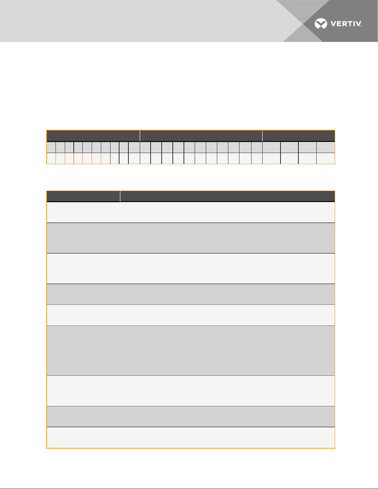
Table 2.1 DSE Model Number
ModelNumber Digits 1 to 10 ModelDetails ModelNumber Digits 1 1 t o 14
1 2 3 4 5 6 7 8 9 10 11 12 1 3 14 15 1 6 17 18 1 9 20 21 22 23 24 25
D A 2 5 0 D P 3 A T 0 2 0 8 1 1 L 0 B 0 P 1 2 3 S
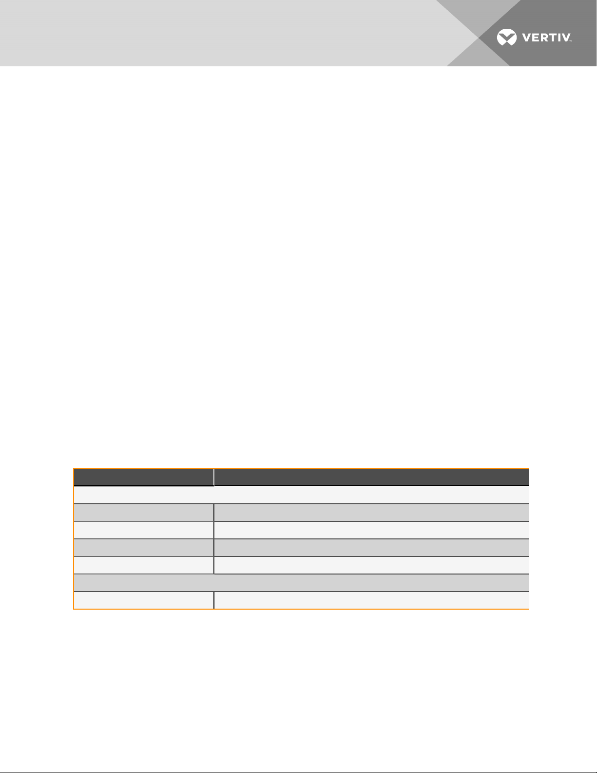
Table 2.2 DSE Model Number Digit Definitions
Digit Description
Digits 1 and 2 = Product Family
DA = Liebert®DSE
Digit3, 4, 5 = Nominal Cooling Capacity, kW
250 = 250 kW
265 = 265 kW
Digit6 = Air Discharge
D = Downflow, bottom discharge
H = Downflow, horizontal discharge
Digit7 = System Type
P = Air cooled, Econ-O-Phase ready
Digit8 = Airflow (Fan Type)
3 = Direct-drive + VFD (plenum)
Digit9 = Voltage
A = 460V - 3ph - 60Hz
B = 575V - 3ph - 60Hz
G = 415 V - 3ph - 50Hz
*For applications that require less than 400V/3ph/50Hz, please consult your loca l sales office for assistance.
Digit10 = Cooling System
T = Tandem with digital scroll, R-410A
P = Ta ndem with digital scroll, R-410A with Power Factor Correction
Digit11 = Humidifier
0 = N o humidifier
Digit12 = Display
2 = Liebert® iCOM™ (High Definition)
2 Nomenclature and Components
7
Page 12
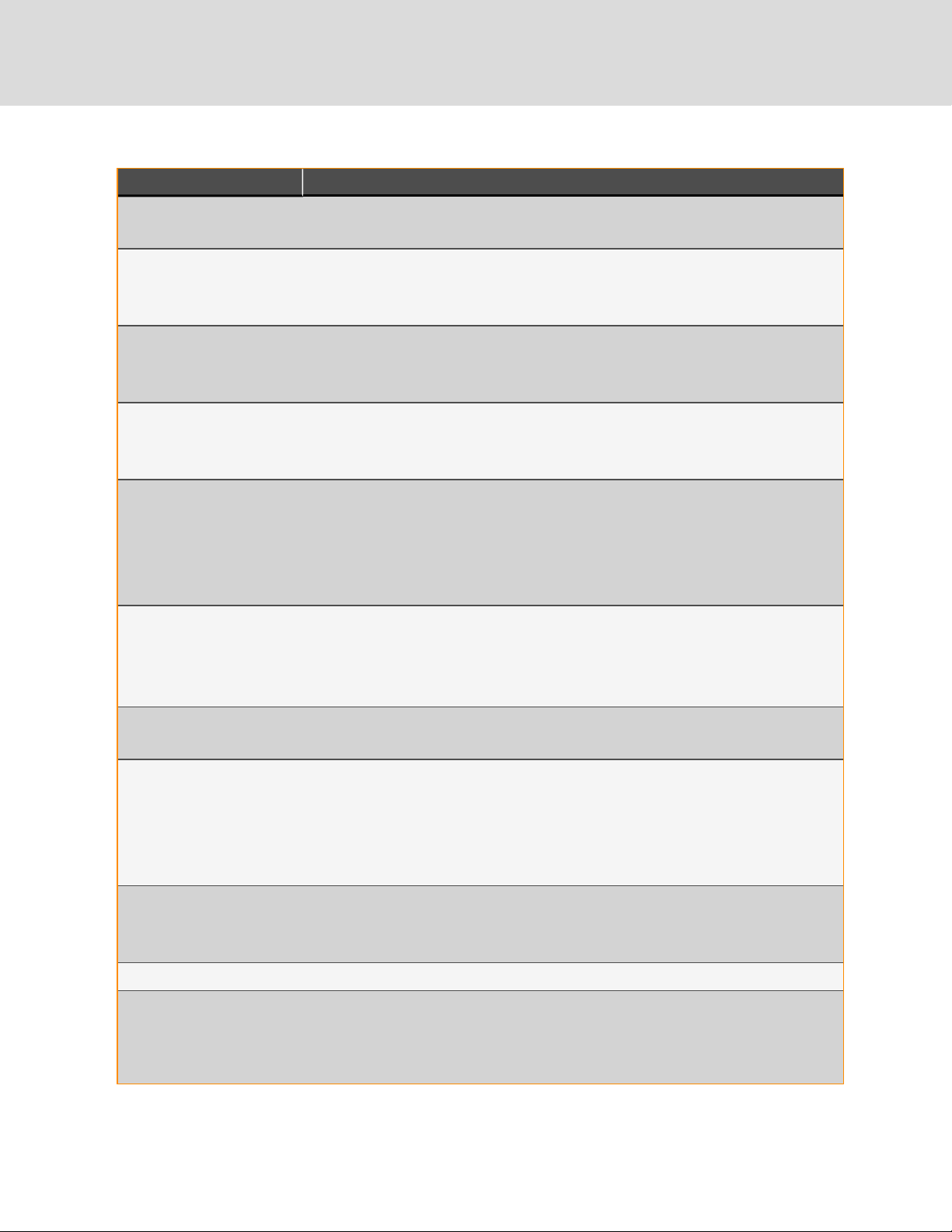
Table 2.2 DSE Model Number Digit Definitions (continued)
Digit Description
Digit13 = Reheat
0 = N one
Digit14 = Air Filter
8 = MERV 8, 4 in .
9 = MERV 11, 4 in .
Digit15 = Coil Option
1 = Non-coated coil, indoor unit
2 = Coated coil, indoor unit
Digit16 = Enclosure Option
1 = Color standard
2 = Color optional
Digit17 = High voltage option
L = Locking disconnect
5 = Locking disconnect, with condensate pump
S = Dual locking disconnect with reversing starter and condenser subfeed
9 = Dual locking disconnect with reversing starter with condensate pump and condenser subfeed
Digit18 = Option packages
0 = N one
L = Option package #1 - low voltage terminal package contact
D = Low Voltage Terminal Package and Remote Humidifier Contact
Digit19 = Monitoring
B = Base comms and connectivity
Digit20 = Sensors
0 = N one
H = High Temperature Sensor
S = Smoke Sensor
F = Smoke Sensor and High Temperature Sensor
Digit21 = Pa ckaging
P = Domestic
C = Export
Digit22-24 = Factory Configuration Number
Digit25 = Configuration Code
A = No SFAs (Any alpha letter except S)
S = Special fea ture authorization (SFA). A non-standard configuration or feature of the product that requires the local factory
representative to work directly with the fa ctory.
8
Vertiv | Liebert ® DSE Thermal Management S ystem In staller/User Guide
Page 13
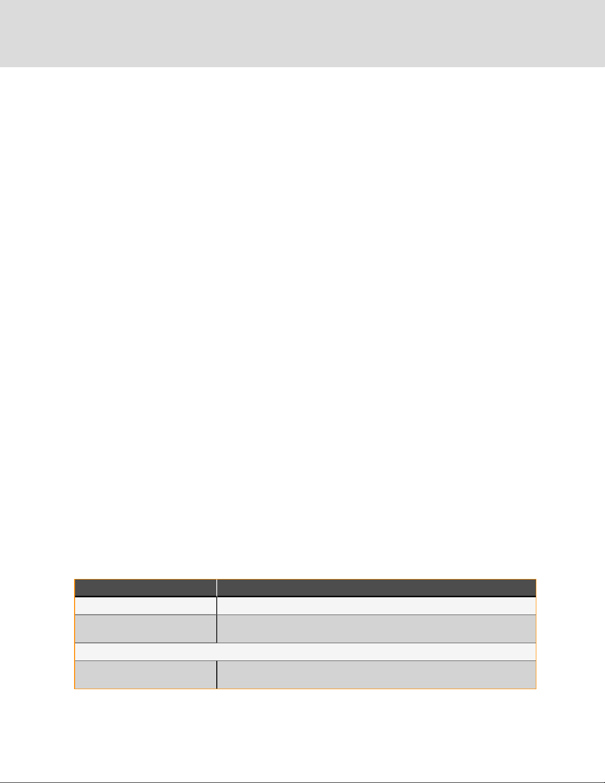
2.2 Component Location
The unit component locations are described in the submittal documents included in the Submittal Drawings.
The following table lists the relevant documents by number and title.
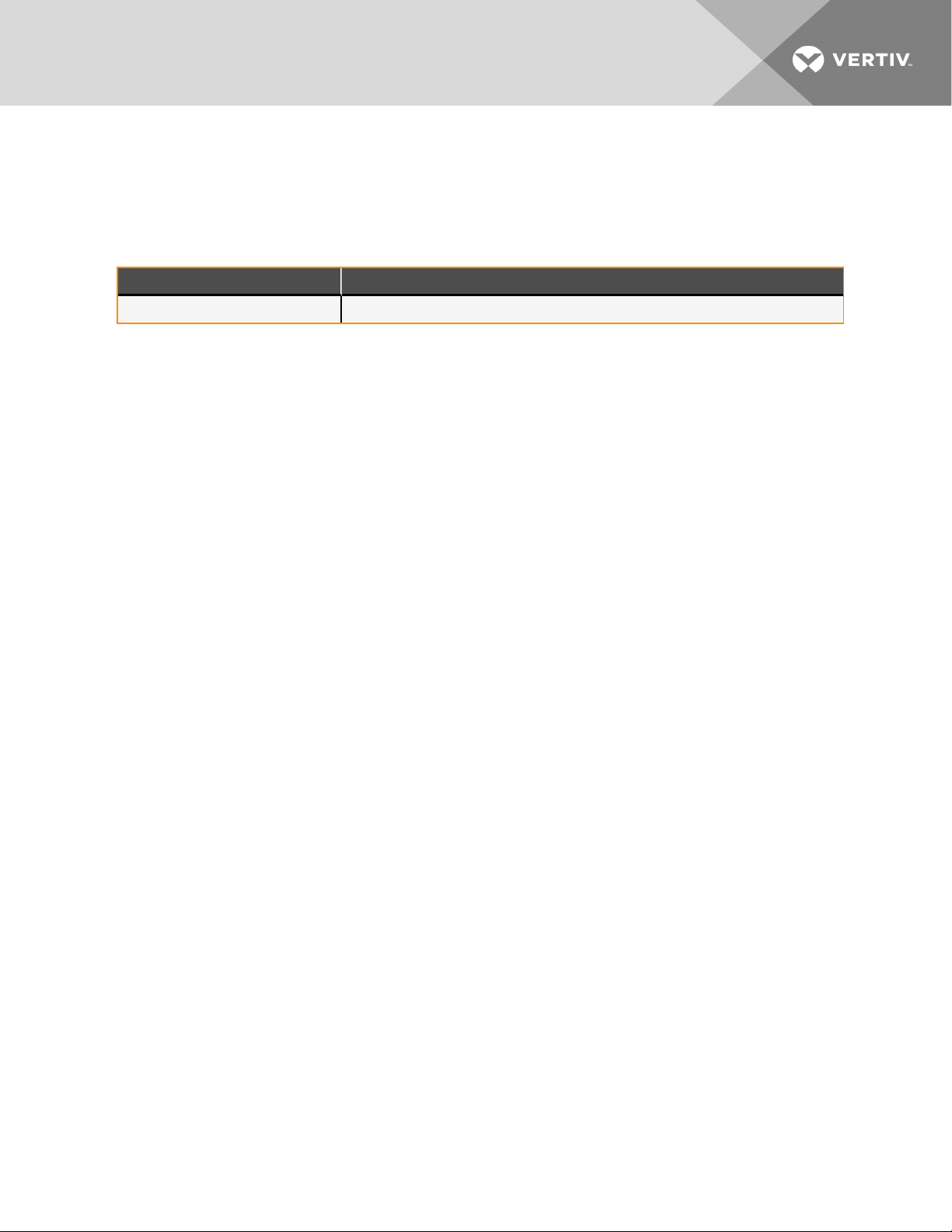
Table 2.3 Component Location Drawings
Docu ment Num ber Title
DPN004368 Liebert®DSECabinet Dimension Data DA250, DA265 with Horizontal Discharge
2 Nomenclature and Components
9
Page 14

This page intentionally left blank
10
Vertiv | Liebert ® DSE Thermal Management S ystem In staller/User Guide
Page 15
3 PRE-INSTALLATION PREPARATIONANDGUIDELINES
NOTE: Before installing unit, determine whether any building alterations are required to run piping, wiring and duct
work. Follow all unit dimensional drawings and refer to the submittal engineering dimensional drawings of individual
units for proper clearances.
Refer to DSE Model Number Digit Definitions, and submittal drawings to determine the type of system being installed and
anticipate building alterations, piping and duct work needed.
The unit dimensions, pipe connection locations, and piping schematics are described in the submittal documents included
in the Submittal Drawings.
• Verify that the floor is level, solid and sufficient to support the unit. See Shipping Dimensions and Unit Weights
on the next page for unit weights.
• Confirm that the room is properly insulated and has a sealed vapor barrier.
• For proper humidity control, keep outside or fresh air to an absolute minimum (less than 5% of total air
circulated in the room).
• Do not install a Liebert® DSE in an alcove or at the end of a long, narrow room.
• Install the units as close as possible to the largest heat load.
• Allow at least the minimum recommended clearances for maintenance and service. See the appropriate
submittal drawings for dimensions.
We recommend installing an under floor water detection system. Contact your Vertiv representative for information.
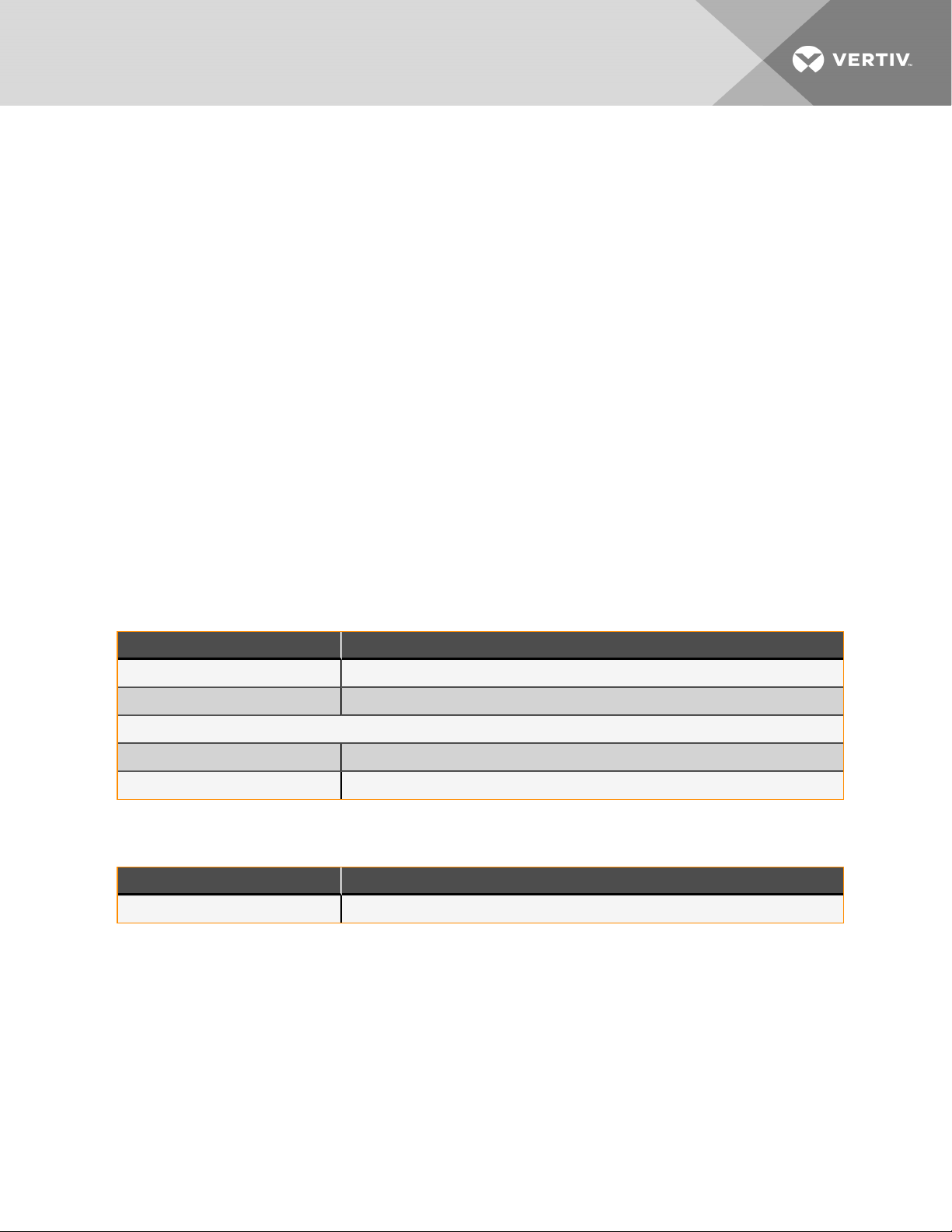
3.1 Planning Dimensions
The unit, floor stand, and plenum dimensions are described in the submittal documents included in the Submittal Drawings.
The following table lists the relevant documents by number and title.
Table 3.1 Dimension Planning Drawings
Docu ment Num ber Title
Downflow Units
DPN004366 Liebert®DSE Cabinet Dimensional Data DA250, DA265 with Horizontal Discharge
DPN004516 Liebert® DSE Cabinet Dimensional Data DA250, DA265 with Bottom Discharge
DPN004514 Liebert® DSE Installation and Service Clearance Data DA250, DA265
DPN004581 Liebert® DSE Floor Planning for Adjacent DA250, DA265 Units
Floor Stands
DPN004511 Liebert®DSE Floor Stand Dimensional Data DA250, DA265
3 Pr e-installation PreparationandG uidelin es
11
Page 16
3.2 Connections and System Setup
• The unit requires a drain, which must comply with all applicable codes. See Connections and System Setup
above, for details.
• If seismic requirements apply, consult your Vertiv representative for information about a seismic rated floor
stand.
NOTE: Seal openings around electrical connection to prevent air leakage. Failure to do so could reduce the unit’s
cooling performance.
The Liebert® DSE controls superheat with an electronic expansion valve (EEV). The EEV controller adjusts the orifice based
on suction pressure and temperature. The EEV control will drive the valve to maintain the superheat setpoint, set in the
Liebert® iCOM™, using a Proportional, Integral, Derivative (PID) routine. The PID control values are set at the factory for
most applications. These default values PID will allow stable superheat control of the unit.
3.3 Operating Conditions
The Liebert® DSE must be operated in a conditioned space within the operating envelope that ASHRAE recommends for
data centers. Operating the DSE outside of this envelope can decrease equipment reliability. Refer to ASHRAE’s
publication, “Thermal Guidelines for Data Processing Environments.”
The recommended maximum for return air temperature is 105°F (40°C) and maximum dew point is 59°F (15°C). The
recommended minimum return air temperature setpoint for the DSE is 85°F(29.4°C).
3.3.1 Humidification Control
The humidifier option is not available on the DA250 or DA265. A remote humidifier contact is available for a standalone
humidifier.
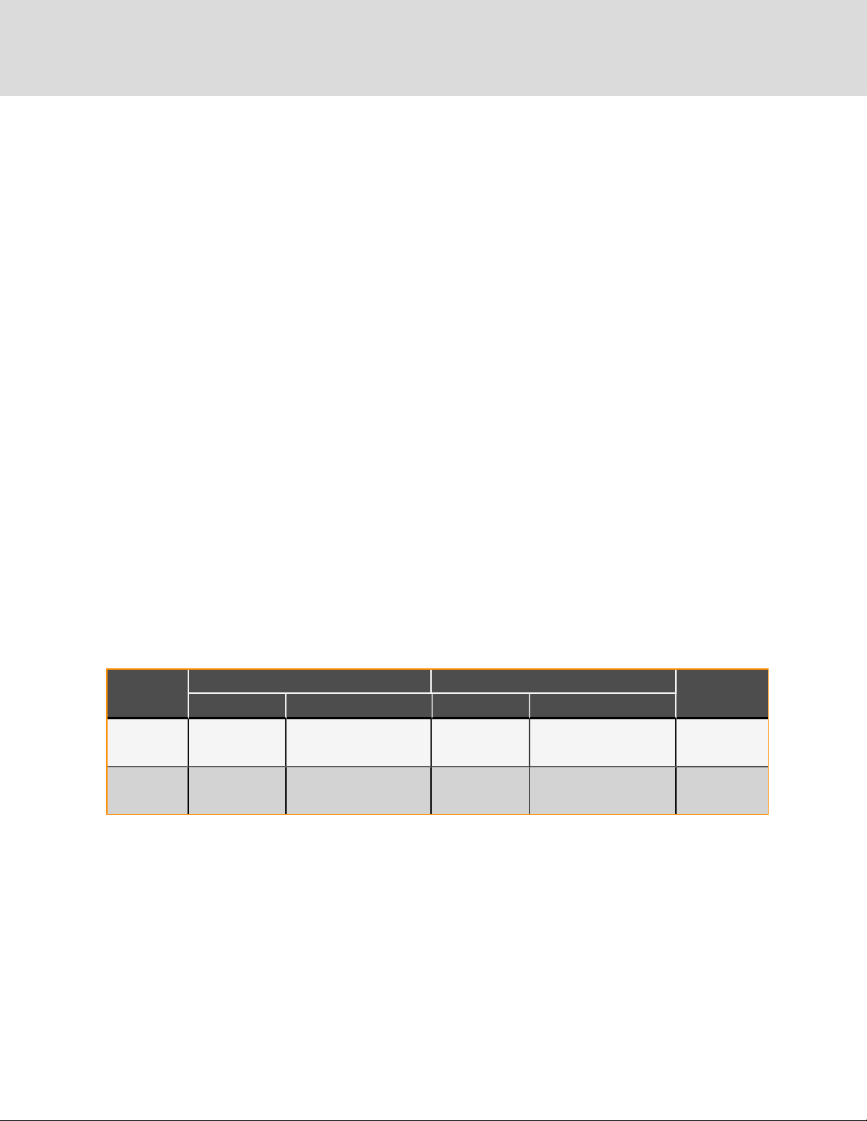
3.4 Shipping Dimensions and Unit Weights
Table 3.2 Downflow Unit Domestic and Export Shipping Dimensions and Weights
Model #
DA250, DA265
Fan section
Ship Weight, lb(kg) Shippin g Dim ensions, in.(mm ) Ship Weight, lb(kg) Shipping Dimensio ns, in.(mm)
6,160
(2,794)
3,281
(1,488)
Dom estic Packaging Export Packaging
90 x 128 x 97
(2,286 x 3, 251 x 2,464)
90 x 128 x 54
(2,286 x 3, 251 x 1,37 2)
6,540 (2,966)
3,676 (1,667)
90.5 x 1,28.5 x 99
(2,299 x 3,264 x 2,515)
90.5 x 1,28.5 x 99
(2,299 x 3,264 x 2,515)
Dry Weight, lb(kg)
4,761
(2,159)
2325
(1,055)
12
Vertiv | Liebert ® DSE Thermal Management S ystem In staller/User Guide
Page 17
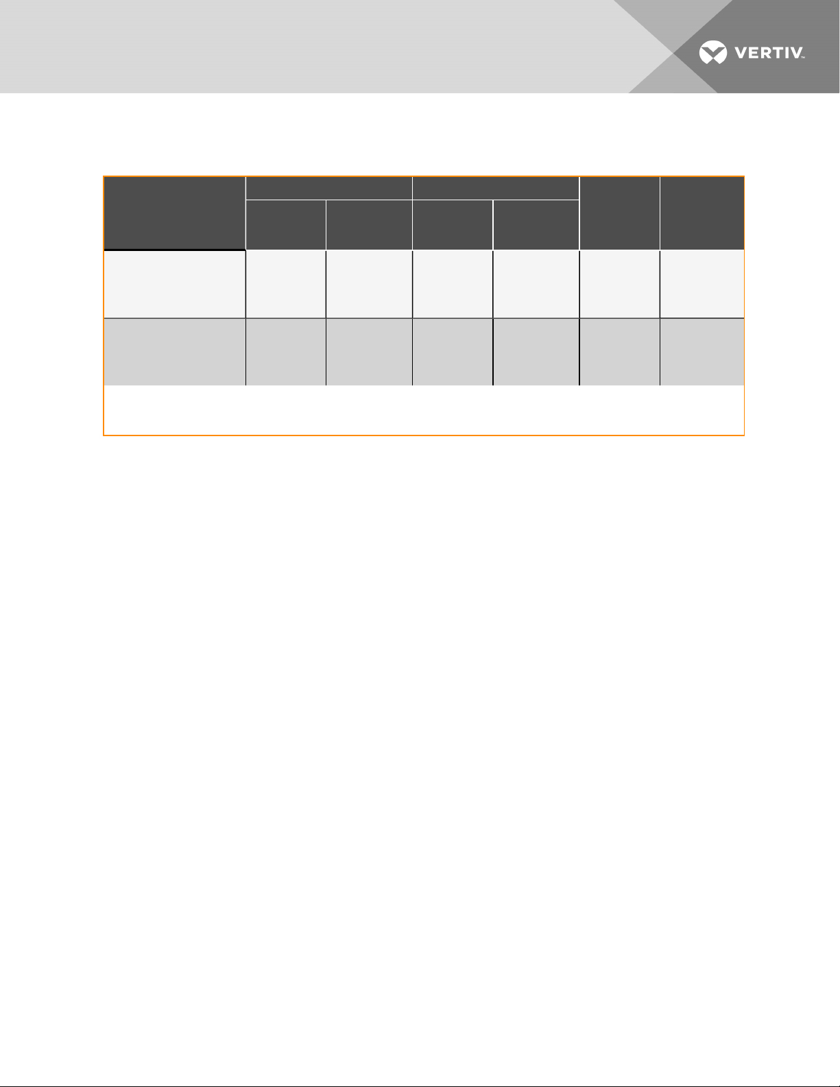
Table 3.3 Liebert® MCV Condenser Unit Domestic and Export Shipping Dimensions and Weights
Dom estic Packaging Export Packaging
Model #
Ship Weight, lb
(kg)
Shippin g
dimension s, ft
(mm)
Ship Weight, lb
(kg)
Shippin g
dimension s, ft
(mm)
Dry Weight, lb
(kg)
Max. Operation
Weight, lb(kg)
1
MCV440
(singleskid)
8-fan+PR250
2
MCV440
(dual skid)
16-fan+PR250
(qty.2)
1
Deduct 120 lbs. (55kg) if no receivers
2
Deduct 220 lbs. (100kg) if no receivers.
5,900
(2,676)
11,580
(5,252)
8ft 6 in. x 14 ft 6
in. x 9ft6in.
(2,591 x 4,420 x
2,896)
8ft 6 in. x 29ft x
9ft6in.
(2,591 x 8,839 x
2,896)
6,200
(2,812)
11,580
(5,252)
9ft 5 in. x 14ft
9in. x 9ft6in.
(2,870 x 4,496 x
28,96)
9ft 5 in. x 29ft
4in. x 9ft6in.
(2,870 x 8,941 x
2,896)
5,800
(2,667)
11,560
(5,243)
5,940
(2,694)
11,880
(5,388)
3 Pr e-installation PreparationandG uidelin es
13
Page 18

This page intentionally left blank
14
Vertiv | Liebert ® DSE Thermal Management S ystem In staller/User Guide
Page 19
4 EQUIPMENT INSPECTION AND HANDLING
WARNING! Risk of top heavy unit falling over. Improper handling can cause equipment damage, injury or
death. Read all of the following instructions and verify that all lifting and moving equipment is rated for the
weight of the unit before attempting to move, lift, remove packaging from or prepare the unit for installation.
CAUTION: Risk of contact with sharp edges, splinters, and exposed fasteners. Can cause injury. Only
properly trained and qualified personnel wearing appropriate, OSHA-approved PPE should attempt to move,
lift, remove packaging from or prepare the unit for installation.
NOTICE
Risk of passageway interference. Can cause unit and/or structure damage. The unit may be too large to fit
through a passageway while on or off the skid. Measure the unit and passageway dimensions, and refer to the
installation plans prior to moving the unit to verify clearances.
NOTICE
Risk of damage from forklift. Can cause unit damage. Keep tines of the forklift level and at a height suitable to
fit below the skid and/or unit to prevent exterior and/or underside damage.
NOTICE
Risk of improper storage. Keep the unit upright, indoors and protected from dampness, freezing temperatures
and contact damage.
Upon arrival of the unit and before unpacking:
• Verify that the labeled equipment matches the bill of lading.
• Carefully inspect all items for visible or concealed damage.
• Report damage immediately to the carrier and file a damage claim with a copy sent to Vertiv or to your sales
representative.
Equipment Recommended for Handling the Unit:
• Forklift
• Slings
• Spreader bars
• Beam trolleys
• Chain hoists
• Gantries
4.1 Packaging Material
All material used to package this unit is recyclable. Please save for future use or dispose of the material appropriately.
4 Equipment Inspection and Hand lin g
15
Page 20

4.2 Handling the Unit while Packaged
If possible, transport the unit with a forklift
When using a forklift:
• Make sure that the lift has adjustable forks, and are spread to the widest allowable distance to still fit under the
skid.
• Make sure that the fork length is suitable for the skid length. Skid length is 128in. (3251mm).
• If the unit must be lifted higher than 2in.(51mm) to 4in. (102 mm), all personnel not directly involved in
moving the unit must be 20ft. (5m) or farther from the unit.
4.3 Unpacking the Unit
Remove exterior package material from around, and on top of the unit.
Figure 4.1 Unpacking the Unit
16
Vertiv | Liebert ® DSE Thermal Management S ystem In staller/User Guide
Page 21
4.4 Removing the Unit from the Skid
NOTE: If you do not follow these steps, damage could occur to the panels and base of the unit.
1. Referring to Figure 4.2 below, use a 9/16 in. socket driver to remove the lag screws (24 total) from the four
corner brackets to detach the unit from the skid.
Figure 4.2 Remove Corner Brackets
4 Equipment Inspection and Hand lin g
17
Page 22
2. Open the door indicated in Figure 4.3 below, and locate the rigging fastener kit that is secured to the bottom
base inside the door.
3. Using the instructions included in the kit, install the rigging hardware for lifting the unit from the skid. Figure 4.3
below, shows an example of one of the eye nuts installed.
Figure 4.3 Locate the Rigging Fastener Hardware Kit
18
Vertiv | Liebert ® DSE Thermal Management S ystem In staller/User Guide
Page 23

4. Attach the recommended rigging equipment to the eye nuts installed in Step 3.
5. Using the rigging equipment, lift the unit from the skid, and remove the skid from under the unit, see Figure 4.4
below.
Figure 4.4 Lifting Unit and Removing Skid
4 Equipment Inspection and Hand lin g
19
Page 24
6. Use the rigging equipment to move the unit to the final installation location, see Figure 4.5 below.
Figure 4.5 Moving the Unit with Rigging
4.5 Unpacking and Handling the Fan Section
Refer to drawing number 336511 "Instructions Handling/Installation of Fan Section CW/DSE" that is included in the fan
plenum packaging for instructions on uncrating and handling the fan section.
20
Vertiv | Liebert ® DSE Thermal Management S ystem In staller/User Guide
Page 25
5 ELECTRICAL FIELD CONNECTIONS
WARNING! Arc flash and electric shock hazard. Open all local and remote electric power supply disconnect
switches, verify with a voltmeter that power is Off and wear appropriate, OSHA-approved personal protective
equipment (PPE) per NFPA 70E before working within the electric control enclosure. Failure to comply can
cause serious injury or death. Customer must provide earth ground to unit, per NEC, CEC and local codes, as
applicable. Before proceeding with installation, read all instructions, verify that all the parts are included and
check the nameplate to be sure the voltage matches available utility power. The Liebert® controller does not
isolate power from the unit, even in the “Unit Off” mode. Some internal components require and receive
power even during the “Unit Off” mode of the controller. The factory supplied disconnect switch is inside the
unit. The line side of this switch contains live high voltage. The only way to ensure that there is NO voltage
inside the unit is to install and open a remote disconnect switch. Refer to unit electrical schematic. Follow all
local codes.
WARNING! Risk of electric shock. Can cause equipment damage, injury or death. Open all local and remote
electric power supply disconnect switches and verify with a voltmeter that power is off before working within
any electric connection enclosures. Service and maintenance work must be performed only by properly
trained and qualified personnel and in accordance with applicable regulations and manufacturers’
specifications. Opening or removing the covers to any equipment may expose personnel to lethal voltages
within the unit even when it is apparently not operating and the input wiring is disconnected from the
electrical source.
NOTICE
WARNING! Risk of improper wire sizing/rating and loose electrical connections. Can cause overheated wire
and electrical connection terminals resulting in smoke, fire, equipment and building damage, injury or death.
Use correctly sized copper wire only and verify that all electrical connections are tight before turning power
On. Check all electrical connections periodically and tighten as necessary.
WARNING! Risk of wiring damage, short circuits and electric shock. Can cause overheated wiring, smoke, fire,
activation of fire suppression systems and EMS personnel and equipment, building and equipment damage,
injury or death. Insert CSA certified or UL listed bushings into holes and or knockouts used to route wiring
through metal panels to protect the wire insulation from contact with sheet metal edges.
Risk of improper electrical connection of three phase input power. Can cause backward compressor rotation
and unit damage. Service technicians should use a gauge set on the system during the initial startup to verify
that the three phase power is connected properly. Three phase power must be connected to the unit line
voltage terminals in the proper sequence so that the compressors rotate in the proper direction. Incoming
power must be properly phased to prevent compressors from running backward. We recommend checking the
unit’s phasing with proper instrumentation to ensure that power connections were made correctly. We also
recommend verifying discharge and suction pressures during startup to ensure that the compressors are
running in the correct direction.
5 Electrical Field Connections
21
Page 26
NOTICE
Risk of improper power supply connection. Can cause equipment damage and loss of warranty coverage.
Prior to connecting any equipment to a main or alternate power source (for example: backup generator
systems) for startup, commissioning, testing, or normal operation, ensure that these sources are correctly
adjusted to the nameplate voltage and frequency of all equipment to be connected. In general, power source
voltages should be stabilized and regulated to within ±10% of the load nameplate nominal voltage. Also, ensure
that no three phase sources are single phased at any time.
See transformer label for primary tap connections. Installer will need to change transformer primary taps if
applied unit voltage is other than pre-wired tap voltage.
NOTE: Seal openings around piping and electrical connection to prevent air leakage. Failure to do so could reduce the
unit’s cooling performance.
Three phase electrical service is required for all models. Electrical service must conform to national and local electrical
codes. Refer to equipment nameplate regarding wire size and circuit protection requirements. Refer the appropriate
submittal drawing, listed in Table 5.1 below, for electrical service entrances into unit
• Liebert® DSE voltage should be verified with available power supply before installation. Refer to the unit’s
electrical schematic and serial tag for specific electrical requirements. Line voltage electrical service is also
required for all condensers at the location of the condenser.
• For the most reliable operation of the system, the indoor unit and the Liebert® MCV condenser should be on the
same power source. The Liebert® DSE system offers an option for a power feed from the active source on the
indoor unit to the outdoor condenser. This configuration provides the greatest reliability and fastest recovery
during power loss or source change.
• When powering the outdoor condenser from the indoor unit, there is a breaker/fuse on the indoor unit.
• A unit disconnect is standard on the Liebert® MCV skid. However, a site disconnect may be required per local
code to isolate the unit for maintenance. Refer to the unit’s serial tag for specific condenser electrical
requirements.
• Route the supply power to the site disconnect switch and then to a factory provided high voltage enclosure
located on the MCV heat rejection skid.
• A manual electrical disconnect switch should be installed in accordance with local codes and distribution
system. Consult local codes for external disconnect requirements.
The electrical and unit to unit connections are described in the submittal documents included in the Submittal Drawings.
The following table lists the relevant documents by number and title.
Table 5.1 Electrical Field Connection Drawings
Docu ment Num ber Title
DPN004797 Liebert®DSE Electrical Field Connections DA250, DA265 Downflow Models
DPN003886
Unit to Unit Networking
DPN004351
22
Liebert®Heat Rejection Skid CANbus and Interlock Connections Liebert®MCV and Liebert®MCV
EconoPhase and Base Assembly
Liebert®iCOM™ Unit to Unit Network Connections (Liebert® CW, Liebert® CWA, Liebert® DS, Liebert® DSE,
Liebert®P DX, Liebert® PCW
Vertiv | Liebert ® DSE Thermal Management S ystem In staller/User Guide
Page 27
6 PIPING AND REFRIGERANT REQUIREMENTS
All fluid and refrigeration connections to the unit are sweat copper. Factory installed piping brackets must not be removed.
Field installed piping must be installed in accordance with local codes and must be properly assembled, supported,
isolated and insulated. Avoid piping runs through noise sensitive areas, such as office walls and conference rooms.
Refer to specific text and detailed diagrams in this manual for other unit specific piping requirements.
All piping below the elevated floor must be located so that it offers the least resistance to air flow. Careful planning of the
piping layout under the raised floor is required to prevent the air flow from being blocked. When installing piping on the
subfloor, we recommend that the pipes be mounted in a horizontal plane rather than stacked one above the other. Whenever
possible, the pipes should be run parallel to the air flow.
The following pipe connections are required:
• A drain line from the unit.
• A drain line from the secondary drain pan (if applicable).
• Refrigerant piping connections between the evaporator unit and the MCV440 heat rejection skid. See
Refrigerant Piping and Charging on page26.
The pipe connection locations, piping general arrangement and schematics are described in the submittal documents
included in the Submittal Drawings.
The following tables list the relevant documents by number and title.
Table 6.1 Piping General Arrangment Drawings
Docu ment Num ber Title
DPN004476 Piping Schematic, DA125, DA150, DA165 & DA250 with Liebert®MCV
DPN005206 Piping Schem atic, DA265 with Liebert®MCV
Piping Arrangement - Liebert®MCVCondenser and EconoPhase Pump Locations
DPN003965 Liebert® DSEAir Cooled Piping Schematic Liebert®MCV Mounted above Liebert®DA125-250
DPN005207 Liebert® DSE Air Cooled P iping Schematic Liebert® MCV Mounted above DA265
Table 6.2 Piping Connection Drawings
Docu ment Num ber Title
DPN004208 Liebert®DSE Connection Locations, DA250, DA265
6 Pip ing and Refrigerant Requirements
23
Page 28

6.1 Drain Fluid Piping
NOTICE
Risk of water leakage. Can cause severe property damage and loss of critical data center equipment.
The Liebert®DSE requires a water drain connection. Improper installation, application and service practices
can result in water leakage from the unit.
Do not locate the unit directly above any equipment that could sustain water damage.
We recommend installing monitored leak detection equipment for the water supply lines and the internal unit
water lines.
6.1.1 Field Installed, Gravity Fed Drain Line Requirements
NOTICE
Risk of water backing up in the drain line. Leaking and overflowing water can cause equipment and building
damage.
Do not install an external trap in the drain line. This line already has a factory installed trap inside the cabinet.
Installation of a second trap will prevent drain water flow and will cause the water to overflow the drain pan.
Sagging condensate drain lines may inadvertently create an external trap.
Observe the following requirements when installing and routing the drain line:
• The drain line must be sized for 2 gpm (7.6 l/m) flow.
• The drain line must be located so it will not be exposed to freezing temperatures.
• The drain should be the full size of the drain connection.
• The drain line must slope continuously away from the unit. Pitch drain line toward drain a minimum of 1/8in.
(3mm) per 1ft (305mm) of length.
• Drain is trapped internally. Do not externally trap the drain line.
• The drain line must be rigid enough that it does not sag between supports, which unintentionally creates traps.
• The drain line must comply with all applicable codes.
• We recommend installing monitored, under floor leak detection equipment.
24
Vertiv | Liebert ® DSE Thermal Management S ystem In staller/User Guide
Page 29

Figure 6.1 Correct and Incorrect Gravity Drains for Downflow Units
Table 6.3 Gravity Fed Drain Line Figure Descriptions
Item D escription
1 Correct drain installation.
2 Incorrect drain installation.
3 DSEunit.
4 Internal drain.
5 External drain.
6 Continuous downwardslope
7 External trap. Do not trap externally..
8 External trap, although unintentional. Lines must be rigid enough to not bow ov er the top of other objects.
6 Pip ing and Refrigerant Requirements
25
Page 30

6.1.2 Condensate Pump Drain Line Requirements
NOTICE
Risk of water backing up in the drain line. Leaking and overflowing water can cause equipment and building
damage.
Do not install an external trap in the drain line. This line already has a factory installed trap inside the cabinet.
Installation of a second trap will prevent drain water flow and will cause the water to overflow the drain pan.
Sagging condensate drain lines may inadvertently create an external trap.
Observe the following requirements when installing and routing the drain line:
• The drain line must be located so it will not be exposed to freezing temperatures.
• Size the piping based on the available condensate head.
• Drain is trapped internally. Do not externally trap the drain line.
• The drain line must be rigid enough that it does not sag between supports, which unintentionally creates traps.
• We recommend installing monitored, under floor leak detection equipment.
Factory Installed Condensate Pump
If your unit includes an optional condensate pump, the pump is factory installed inside the unit and a 3/4 in. copper sweat
connection is provided on the unit.
6.2 Refrigerant Piping and Charging
WARNING! Risk of over pressurization of the refrigeration system. Can cause explosive discharge of high
pressure refrigerant, loss of refrigerant, environmental pollution, equipment damage, injury, or death. This
unit contains fluids and gases under high pressure. Use extreme caution when charging the refrigerant
system. Do not pressurize the system higher than the design pressure marked on the unit's nameplate.
CAUTION: Risk of excessive refrigerant line pressure. Can cause equipment damage or injury resulting from
tubing and component rupture. Do not close off the refrigerant-line isolation valve for repairs unless a
pressure relief valve is field installed in the line between the isolation valve and the check valve. The
pressure relief valve must be rated 5% to 10% higher than the system design pressure. An increase in
ambient temperature can cause the pressure of the isolated refrigerant to rise and exceed the system design
pressure rating (marked on the unit nameplate).
Consult local building and plumbing codes for installation requirements of additional pressure relief devices when isolation
valves are field installed. Do not isolate any refrigerant circuits from over pressurization protection.
Table 6.4 System Refrigerant Pressures
Maximum Design O perating Pressure (High Side) 530 psig 3655 kPa Noted on the unit serial tag
High Pressure Cut Out Safety Switch 580 psig 4000 kP a Nominal
26
Vertiv | Liebert ® DSE Thermal Management S ystem In staller/User Guide
Page 31

NOTICE
Risk of oil contamination with water. Can cause equipment damage.
Liebert®DSE systems require the use of POE (polyolester) oil. POE oil absorbs water at a much faster rate
when exposed to air than previously used oils. Because water is the enemy of a reliable refrigeration system,
extreme care must be used when opening systems during installation or service. If water is absorbed into the
POE oil, it will not be easily removed and will not be removed through the normal evacuation process. If the oil
is too wet, it may require an oil change. POE oils also have a property that makes them act as a solvent in a
refrigeration system. Maintaining system cleanliness is extremely important because the oil will tend to bring
any foreign matter back to the compressor.
6.2.1 Refrigerant Piping Guidelines forAir CooledSystems
• Field installed interconnecting piping should be properly selected based on local codes and unit labeling.
• Air cooled units ship with a nitrogen holding charge. Do not vent the charge until all refrigerant piping is in
place, ready for connection to the unit and condenser.
• Use copper piping with a brazing alloy with a minimum temperature of 1350°F (732°C), such as Sil-Fos. Avoid
soft solders, such as 50/50 or 95/5.
• Use a flow of dry nitrogen through the piping during brazing to prevent formation of copper oxide scale inside
the piping. When copper is heated in the presence of air, copper oxide forms. POE oils will dissolve these
oxides from inside the copper pipes and deposit them throughout the system, clogging filter driers and
affecting other system components.
• A pure dry nitrogen flow of 1-3 ft3/min (0.5-1.5 l/s) inside the pipe during brazing is sufficient to displace the air.
Control the flow using a suitable measuring device.
• Ensure that the tubing surfaces to be brazed are clean and that all burrs have been removed from the ends of
the tubes.
• Ensure that all loose material has been cleaned from inside the tubing before brazing.
• Protect all refrigerant line components within 18in. (460mm) of the brazing site by wrapping them with a wet
cloth or with a suitable heat sink compound.
• Isolate piping from building using vibration isolating supports.
• The Liebert® MCV heat rejection skid cannot be installed below the evaporator.
• The DA250 is used with a Liebert® MCV heat rejection skid with receiver tanks. For this system, the outlet of
the receivers on the outdoor Liebert® MCV heat rejection skid must be higher than the elevation of the
electronic expansion valves (EEVs) inside of the indoor unit. If the vertical height of the receiver outlet is
greater than 60 ft. (18.3m) above the EEV, consult the factory. Refer to DPN003965 in Submittal Drawings on
page61.
• The DA265 is used with a Liebert® MCV heat rejection skid with without receiver tanks. For this system, the
bottom of the condenser coil on the outdoor Liebert® MCV heat rejection skid must be higher than the
elevation of the EEV inside of the indoor unit. If the vertical height between the condenser coil bottom and the
EEV is greater than 60 ft. (18.3m), consult the factory. Refer to DPN005207 in Submittal Drawings on page61
• Install traps on hot gas (discharge) lines at the base of vertical risers over 5ft.(1.5m) and then for vertical rises
over 25 ft. (7.6 m), install a trap in 20 ft (6 m) increments or evenly-divided over the vertical rise. The DA250
with piping out the top of the unit has internally installed traps on the hot gas lines.
• Pitch horizontal hot gas piping down at a minimum rate of 1/2in.per 10ft. (42mm per 10m) so that gravity will
aid in moving oil in the direction of refrigerant/oil flow.
• Consult factory if piping run exceeds 200ft. (61m) linear length or 300ft.(91m) equivalent length.
6 Pip ing and Refrigerant Requirements
27
Page 32

• Keep piping clean and dry, especially on units with R-410A refrigerant.
• Avoid piping runs through noise-sensitive areas.
• Do not run piping directly in front of discharge air stream.
• Refrigerant oil – do not mix oil types (see Compressor Oil).
Refer to ASHRAE Refrigeration Handbook for general, good-practice refrigeration piping. The indoor cooling unit has a
factory installed high pressure safety switch in the high side refrigerant circuit. A fusible plug is installed in each Liebert®
DSE receiver.
NOTE: All indoor and outdoor field refrigerant piping must be insulated 1/2 in. minimum. All outdoor insulation must
be UV and ozone resistant.
• Refer to Refrigerant Line Sizes and Equivalent Lengths below, for recommended refrigerant piping sizes based
on equivalent pipe lengths.
• Refer to Refrigerant Charge Requirements for Air Cooled Systems on the facing page, for the refrigerant-charge
requirements of the system.
• Refer to Charging DA250 Air Cooled Systems (Liebert® MCV440 with Receivers) on page33, for charging
information.
6.2.2 Piping Layout and Condenser Positioning
The piping layout and condenser positioning is detailed in the submittal documents included in the Submittal Drawings.
The following table lists the relevant documents by number and title.
Table 6.5 Refrigeration Piping Layout and Condenser Positioning Drawings
Docu ment Num ber Title
DPN003965 Liebert®DSE Air Cooled Piping Schematic Liebert® MCV Mounted above Liebert® DA125-250
DPN005207 Liebert® DSEAir Cooled Piping Schematic Liebert®MCV Mounted above DA265
6.2.3 Refrigerant Line Sizes and Equivalent Lengths
Table 6.6 Recommended Refrigerant Line Sizes, OD Copper
Model
Equivalent Length Hot Gas Line, in. Liquid Line, in.
50 ft. (15 m) 1-5/8 1-3/8
100 ft. (30 m) 1-5/8 1-3/8
150 ft. (45 m ) 1-5/8* 1-3/8*
300 ft. (91 m) 1-5/8* 1-3/8*
*The DA250 and DA265 units can be extended to a maximum 200 ft (61m) linear or 300 ft (91m) equivalent length.
Source: DPN000788 Rev. 13
DA250
DA265
NOTE: See the piping schematics for your system in Submittal Drawings. For installations using pre-fabricated heat
rejection skids, included piping must be factored into total equivalent length calculation. Please consult factory for
details.
28
Vertiv | Liebert ® DSE Thermal Management S ystem In staller/User Guide
Page 33

6.2.4 Refrigerant Charge Requirements for Air Cooled Systems
The following tables provide the refrigerant charge requirements for the Liebert® DSE, connected piping, and condenser
options.
Table 6.7 Indoor Unit Approximate Refrigerant Charge for R-410A Per Circuit
Indoo r Unit Type Model Circuit 1 (Outercircuit), lb(kg) Circuit 2 (In nercircuit), lb(kg)
Air cooled DA250 25 (11. 3) 25 (11. 3)
Air cooled DA265 25 (11 .3) 35 (15.9)
*System Charge: Indoor unit, MCV440 heat rejection skid with EconoPhase (PRE)and refrigerant lines.
For system charges over 200 lb. (90.7kg), consult your Vertiv representative.
See Table 9.3 on page47 for the recommended oil for the system.
The values in this table a nd in the following tables are needed in order to calculate the full system charge:
• Ta ble 6.8 below
• Ta ble 6.9 below
Table 6.8 MCV Heat Rejection Skid Refrigerant Charge for R-410A per Circuit Including PRE
Heat Rejection Skid* System # Circuit Number
Charge per Circuit, lb (kg) (With or
Without Receivers)
MCV440 Single skid with (1) PRE
unit
MCV440 Dual skid with (2) PRE units
*The heat rejection skid contains Liebert® MCV condenser(s), Liebert® DSE receiver(s)when used with a DA250 system, Liebert®EconoPhase PRE units(s),
and all internal piping. Liebert® DSE receivers are not used with a DA265 system.
1
1
2
1 62 (28.1)
2 62 (28.1)
1 62 (28.1)
2 62 (28.1)
1 62 (28.1)
2 62 (28.1)
Table 6.9 Interconnecting Piping Refrigerant Charge for R-410A, lb per 100ft (kg per 30m)
Line Size, OD, in. Liquid Line Hot Gas Line
1-3/8 51.5 (23.0) 5.9 (2.6)
1-5/8 — 8.4 (3.7)
Source: DPN003099, Rev. 1
6 Pip ing and Refrigerant Requirements
29
Page 34

6.2.5 Additional Oil Requirements forScrollandDigital ScrollCompressors
NOTICE
Risk of improper compressor lubrication. Can cause compressor and refrigerant system damage.
Failure to use oil types, viscosities and quantities recommended by the compressor manufacturer may reduce
compressor life and void the compressor warranty. See Compressor Oil Types for R-410A Refrigerant, for the
recommended oil for the system.
• Do not mix polyolester (POE) and mineral-based oils.
• Do not mix oils of different viscosities.
• Consult your Vertiv sales representative, visit https://www.Vertiv.com/en-us/support/, or contact the
compressor manufacturer if questions arise.
See 6.2.5 above, for the amount required for various system charge levels.
In addition to oil added based on system charge, additional oil is required for discharge line field installed traps. Standard
formed tube traps are required, see Figure 6.2 below, and Table 6.11 on page32, because straight tubes and fittings used
as traps require much more oil and the length of the straight tube can vary.
After the system has been fully charged with refrigerant, use a hand pump to add the additional oil at the suction side of the
system while the system is running.
The amount of oil added by field service must be recorded on the tag marked “Oil Added Field Service Record,” attached
to each compressor. The date of oil addition must be included as well.
Figure 6.2 Standard Formed Tube Trap Versus Straight Tubes and Fittings Trap
Item Description
1 Standard forme d t ube tr ap
2 Stra ight t ubes and fit ti ngs t rap
30
Vertiv | Liebert ® DSE Thermal Management S ystem In staller/User Guide
Page 35

Table 6.10 Additional Oil Required per Refrigerant Charge
Refrigerant System C harge
Per Circuit, lb (kg) *
< 40 (18. 1) 0
40 (18.1) 10 (300)
50 (22.7) 1 8 (530)
60 (27.2) 26 (770)
70 (31. 8) 34 (1010)
80 (36.3) 42 (1240)
90 (40.8) 50 (1480)
100 (45.4) 58 (1720)
110 (49.9) 66 (1950)
120 (54.4) 74 (2190)
130 (59.0) 82 (2430)
140 (63.5) 90 (2660)
150 (68.0) 98 (2900)
Model
DA250, DA265
Additional Oil Required Per Circuit, oz (ml)
160 (72. 6) 106 (3130)
170 (77. 1) 11 4 (3370)
180 (81.6) 1 22 (3610)
190 (86.2) 130 (3840)
200 (90.7 ) 138 (4080)
System Charge: indoor unit, MCV heat rejection skid, refrigerant lines. Calculated per circuit.
For system charges over 200 lb. (90.7kg), c onsult your Vertiv representative.
See Compressor Oil Types for R-410A Refrigerant, for the recommended oil for the system.
Source:DPN003950 Rev. 6
6 Pip ing and Refrigerant Requirements
31
Page 36

Table 6.11 Volume of Oil in Standard Form Trap by Pipe Diameter
Pipe d iameter, in. Oil volume, oz (ml)
1/2 0.2 (5.9)
5/8 0.4 (11.8)
3/4 0.6 (17.7 )
7/8 0.9 (26.6)
1-1/8 1.8 (53.2)
1-3/8 3.3 (97.6)
1-5/8 5.5 (162. 7)
Source: DPN003950, Rev. 6
6.2.6 Evacuation, Leak Testing, and Charging Air Cooled Systems
Two discharge lines and two liquid linesmust be field installed between the indoor unit and the outdoor condenser.
NOTE: Keep the evaporator unit, receiver (if equipped), and condenser closed with their factory charge of dry
nitrogen while all field piping is installed. Keep the field piping clean and dry during installation. Do not allow it to
stand open to the atmosphere. When all the field interconnecting piping is in place, vent each outdoor unit’s dry
nitrogen charge and connect to the field piping. Finally, vent the evaporator unit's dry nitrogen charge and make its
piping connection last. Follow all proper brazing practices, including a dry nitrogen purge to maintain system
cleanliness. The condenser connection pipes must be wrapped with a wet cloth to keep the pressure and temperature
sensors cool during any brazing.
Evacuation and Leak Testing Air Cooled Systems
For proper leak check and evacuation, you must open all system valves and account for all check valves.
NOTE: The system includes a factory installed check valve and an additional downstream Schrader valve with core in
the compressor discharge line. Proper evacuation of the condenser side of the compressor can be accomplished only
using the downstream Schrader valve. See the appropriate piping schematic for your system in Submittal Drawings.
1. Starting with Circuit #1, open the service valves and place a 150 PSIG (1034kPa) of dry nitrogen with a tracer
of refrigerant. Check the system for leaks with a suitable leak detector.
2. With pressure still in Circuit #1, open the compressor service valves in Circuit#2.
• If pressure increases in Circuit#2, the system is cross-circuited and must be re-checked for proper
piping.
• If there is no pressure increase, repeat step1 on Circuit#2.
3. After completion of leak testing, release the test pressure, (observe local code) and pull an initial deep vacuum
of 500microns on the system with a suitable pump.
4. After fourhours, check the pressure readings and, if they have not changed, break vacuum with dry nitrogen.
Pull a second and third vacuum to 500 microns or less. Re-check the pressure after twohours.
When the three checks are complete, remove the jumper hose from the service valve fitting and the condenser,
and proceed to Charging DA250 Air Cooled Systems (Liebert® MCV440 with Receivers) on the facing page.
32
Vertiv | Liebert ® DSE Thermal Management S ystem In staller/User Guide
Page 37

Charging DA250 Air Cooled Systems (Liebert® MCV440 with Receivers)
NOTICE
Risk of improper refrigerant charging. Can cause equipment damage.
R-410A is a blended refrigerant and must be introduced and charged from the cylinder only as a liquid.
When adding liquid refrigerant to an operating system, it may be necessary to add the refrigerant through the
compressor suction service valve. Care must be exercised to avoid damage to the compressor. We recommend
connecting a sight glass between the charging hose and the compressor suction service valve. This will permit
adjustment of the cylinder hand valve so that liquid can leave the cylinder while allowing vapor to enter the
compressor.
NOTICE
Risk of improper operation. Can cause compressor failure.
Operating the unit with the EEV closed can cause compressor failure. The reheat and humidifier are disabled. A
minimum of 20 psig (138 kPa) must be established and maintained for the compressor to operate. The
charging function can be reset as many times as required to complete
To charge the system:
1. Check the nameplate on the indoor unit for refrigerant type to be used. Unit control configurations differ
depending on refrigerant type.
2. The unit must be operating during charging, refer to Checklist for Completed Installation on page37
3. Calculate the amount of charge for the system. See Refrigerant Charge Requirements for Air Cooled Systems
on page29.
4. Accurately weigh in as much of the system charge as possible before starting the unit. Do not exceed the
calculated charge by more than 0.5lb(0.37kg).
5. Close the MVC heat rejection skid disconnect switch.
• We recommend charging the unit with the return air setpoint between 75°F and 85°F (24°C and 29°C).
• The return air temperature to the unit being charged must be stable and must be maintained greater
than 65°F(18°C). If this is not possible due to lack of heat load, then the load banks must be used to offset
the cooling load during startup. See Target Refrigerant Level in Sight Glasses at Outdoor Temperatures
on the next page.
6. Close the Liebert® DSE disconnect switch.
6 Pip ing and Refrigerant Requirements
33
Page 38

7. In the Service menu of the Liebert® iCOM™ controller, select Diagnostics/Service > Diagnostics:
a. Enable Manual Mode.
NOTE: Manual Mode will time out after 30 minutes.
b. In the search box, enter E177 and press Enter.
Two parameters appear in the Parameter Directory (E177.1 and E177.2).
Press the Gear icon in the upper right corner.
Select Make Writeable.
Change E177.1 and E177.2 from 15 minutes to 2 minutes.
This reduces the superheat setpoint from 24°F (13.3 °C) to 13°F (7.2°C) in two minutes.
c. In Evaporator Fan options set Motors to On to operate the fan during Manual Mode.
d. In Compressor Circuit 1 options, set Compressor Mode to Charge to operate Compressors 1A and 1B at
full capacity. Turn Compressor 1A and 1B to On. The EEV will modulate to control superheat setpoint
e. Reset the charge function as many times as needed to complete unit charging.
NOTE: You must establish and maintain a minimum 20psig (138kPa) for the compressor to operate.
f. Repeat step 7 for Compressor Circuit 2.
8. Check the refrigerant level in the refrigerant level sight glasses on each receiver after the unit has been
operating for at least 15minutes.
NOTE: Each receiver at the condenser has two sight glasses and the refrigerant level varies with outside temperature.
9. Adjust the refrigerant level in each circuit to meet the level shown in Target Refrigerant Level in Sight Glasses
at Outdoor Temperatures below.
10. After adjusting the refrigerant, allow the system to operate an additional 15minutes before checking for the
need of further adjustment.
11. Repeat the procedure for the second circuit.
NOTE: A digital scroll compressor can have a clear unit sight glass on the liquid line only when operating at 100%
capacity. When operating with a receiver, the unit sight glass might not become clear even when operating at 100%
capacity. When operating below 100%, the unit sight glass may show bubbles with each 15 second unloading cycle.
Target Refrigerant Level in Sight Glasses at Outdoor Temperatures
• 40°F (4.5°C) and lower—bottom sight glass is 3/4 full
• 40°F (4.5°C) and higher—bottom sight glass is full
If the return air temperature cannot be maintained between 75°F and 85°F (24°C and 29°C) due to lack of load, then the
liquid level receiver must be adjusted to the following if return air is between 65°F and 75°F (18°C and 24°C):
• 40°F (4.5°C) and lower—Charge to the bottom of the top sight glass.
• 40°F (4.5°C) and higher—Top sight glass is 1/4 full.
34
Vertiv | Liebert ® DSE Thermal Management S ystem In staller/User Guide
Page 39

Charging DA265 Air Cooled Systems (Liebert® DA265 without Receivers)
NOTICE
Risk of improper refrigerant charging. Can cause equipment damage.
R-410A is a blended refrigerant and must be introduced and charged from the cylinder only as a liquid.
When adding liquid refrigerant to an operating system, it may be necessary to add the refrigerant through the
compressor suction service valve. Care must be exercised to avoid damage to the compressor. We recommend
connecting a sight glass between the charging hose and the compressor suction service valve. This will permit
adjustment of the cylinder hand valve so that liquid can leave the cylinder while allowing vapor to enter the
compressor.
NOTICE
Risk of improper operation. Can cause compressor failure.
Operating the unit with the EEV closed can cause compressor failure. The reheat and humidifier are disabled. A
minimum of 20 psig (138 kPa) must be established and maintained for the compressor to operate. The
charging function can be reset as many times as required to complete.
To charge the system:
1. Check the nameplate on the indoor unit for the refrigerant type to be used. Unit control configurations differ
depending upon the refrigerant type.
2. The unit must be operating during charging. Refer to Checklist for Completed Installation on page37
3. Calculate the amount of charge for the system. See Refrigerant Charge Requirements for Air Cooled Systems
on page29.
4. Accurately weigh in as much of the system charge as possible before starting the unit. Do not exceed the
calculated charge by more than 0.5 lb (0.37 kg).
5. Close the Liebert® MCV heat rejection skid disconnect switch.
• Unit must be charged with the return air within +/- 10°F (5.5° C) of the operating point.
• If the operating point changes, the charge may need to be adjusted according to the new operating
point.
• The return air temperature to the unit being charged must be stable. If this is not possible due to the lack
of heat load, then the load banks must be used to offset the cooling load during startup.
6. Close the Liebert® DSE disconnect switch.
7. In the Service menu of the Liebert® iCOM™ controller, select Diagnostics/Service > Diagnostics.
a. Enable Manual Mode.
NOTE: Manual mode will time out after 30 minutes.
b. In the Search Box type E177 and press Enter.
6 Pip ing and Refrigerant Requirements
Two parameters appear in the Parameter Directory (E177.1 and E177.2).
Press the Gear icon in the upper right corner.
Select Make Writeable.
Change E177.1 and E177.2 from 15 minutes to 2 minutes.
This will reduce the superheat setpoint from 24°F (13.3° C) to 13°F (7.2° C) degrees in two minutes.
35
Page 40

c. In the Evaporator Fan options, set Motors to On to operate the fan during Manual Mode.
d. In Compressor Circuit 1 options, set the Compressor Mode to Charge to operate Compressors 1A and 1B
at full capacity. Turn Compressor 1A and 1B to On. The EEV will modulate to control superheat setpoint.
e. Reset the charge function as many times as needed to complete unit charging.
NOTE: You must establish and maintain a minimum 20 psig (138 kPa) for the compressor to operate.
8. Check out the subcooling using the Schrader port on the liquid line just before the expansion valve. Superheat
should be around 13°F (7.2°C) before verifying subcooling.
9. Adjust the refrigerant level to meet the subcooling shown in Table 6.12 below
10. After adjusting the refrigerant, allow the system to operate an additional 15 minutes before checking the need
of further adjustment.
NOTE: A digital scroll compressor can have a clear unit sight glass on the liquid line only when operating at 100%
capacity. When operating below 100% capacity, the unit sight glass may show bubbles with each 15 second unloading
cycle.
Table 6.12 Target Subcooling at Outdoor Temperature
Outdo or Ambient Subco oling
°F °C °F °C
-30 -34.4 10 5.5
-15 -26.1 10 5.5
0 -17. 8 10 5.5
15 -9.4 1 0 5.5
30 -1.1 1 0 5.5
45 7.2 1 0 5.5
60 15.6 10 5.5
75 2 3.9 10 5.5
85 29.4 1 0 5.5
95 35 10 5.5
105 40.6 12 6.7
115 46.1 14 7.8
Subcoolingshould be within ± 3°F (1. 7°C)
11. Repeat steps 7 through 10 for Compressor Circuit 2.
12. Change E177.1 and E177.2 back to 15 minutes after both circuits are charged.
36
Vertiv | Liebert ® DSE Thermal Management S ystem In staller/User Guide
Page 41

7 CHECKLIST FOR COMPLETED INSTALLATION
7.1 Moving and Placing Equipment
1. Unpack and check received material.
2. Make sure that proper clearance for service access has been maintained around the equipment.
3. Check that equipment is level and mounting fasteners are tight.
7.2 Electrical Installation Checks
1. Check that supply voltage and phase matches equipment nameplate.
2. Check that power wiring connections completed to the disconnect switch, evaporator unit and heat rejection
equipment.
3. Check that power line circuit breakers or fuses have proper ratings for equipment installed.
4. Control wiring connections completed between indoor evaporator and heat rejection equipment.
5. Ensure that all internal and external high and low voltage wiring connections are tight.
6. Confirm that unit is properly grounded to an earth ground.
7. Check that control transformer setting matches incoming power.
8. Confirm that electrical service conforms to national and local codes.
9. Check blowers and compressors for proper rotation.
7.3 Piping Installation Checks
1. Check that piping is completed to refrigerant loop.
2. Confirm that piping has been leak checked.
3. Check that additional oil has been added for system charges over 40 pounds (18.1kg) per circuit. See
Additional Oil Requirements forScrollandDigital ScrollCompressors on page30.
4. Check that piping is properly sized, sloped and trapped as shown in the piping schematics.
5. Check piping inside and outside of equipment for proper support and adequate spacing to prevent rub
through.
6. Ensure that factory clamps have been reinstalled.
7. Confirm that the drain line is connected, not obstructed, and pitched per local code.
7.4 Other Installation Checks
1. Make sure that ducting or plenum assembly complete (if required), maintain access to filters.
2. Check that filters are installed.
3. Check fasteners that secure motors—some may have become loose during shipment.
4. Verify water detection is properly installed around all units (recommended).
5. Confirm that blower drive system rotates freely.
6. Check all fans are free of debris.
7. Set fan airflow calibration voltage. Refer to Table 7.1 on the next page, for values. The values are set in the
iCOM™ Service menu > Setpoints > Fan.
7 Checklist for Completed Installation
37
Page 42

Table 7.1 Airflow Calibration Voltage DA250
Air Flow* at 0.1in.(25Pa) ESP Air Flow C alibration Vo ltage
CFM CMH 60 Hz 50 Hz
25,0 00 42480 4.66 5.57
26,000 44179 4.83 5.78
27, 000 45878 5. 00 5.98
28,000 47578 5. 17 6.19
29,000 49277 5.34 6.39
30,000 50976 5.52 6.60
31,000 52675 5.69 6.81
32,000 54374 5.86 7. 01
33,000 56074 6.03 7. 22
34,000 57773 6.20 7.42
35,000 59472 6.38 7. 63
36,000 61171 6.55 7.83
37,000 62870 6.72 8.04
38,000 64570 6.89 8.24
39,000 66269 7.06 8.45
40,000 67968 7.23 8.65
41,000 69667 7.41 8.86
42,000 71366 7.58 9.07
43,000 73066 7.75 9.27
44,000 74765 7.92 9.48
*Maximum air flow calibration voltage must be adjusted based on the required air flow.
38
Vertiv | Liebert ® DSE Thermal Management S ystem In staller/User Guide
Page 43

Table 7.2 Air Flow Calibration Voltage DA265
Air Flow* at 0.1in.(25Pa) ESP Air Flow C alibration Vo ltage
CFM CMH 60 Hz 50 Hz
25000 42,475 5.42 6.49
26,000 44,174 5.61 6.71
27, 000 45,873 5.80 6.94
28,000 47,572 5.99 7.1 7
29,000 49,271 6.18 7.40
30,000 50,970 6.37 7.62
31,000 52669 6.56 7 .85
32,000 54368 6.75 8.08
33,000 56,067 6.94 8.31
34,000 57,766 7. 13 8.54
35,000 59,465 7.32 8.76
36,000 61, 164 7.52 8.99
37,000 62,863 7.7 1 9.22
38,000 64,562 7. 90 9.45
39,000 66,261 8.09 9.67
40,000 67,960 8.28 9.90
41,000 69,659 8.47 -
42,000 7 1358 8.66 -
43,000 73,057 8.85 -
44,000 74,756 9.04 -
45000 76,455 9.23 -
46000 78,154 9.42 -
47000 79,853 9.61 -
48000 81,552 9.80 -
49000 83,251 9.99 -
*Maximum air flow calibration voltage must be adjusted based on the required air flow.
7 Checklist for Completed Installation
39
Page 44

This page intentionally left blank
40
Vertiv | Liebert ® DSE Thermal Management S ystem In staller/User Guide
Page 45

8 INITIAL STARTUP CHECKS ANDCOMMISSIONINGPROCEDURE
FORWARRANTYINSPECTION
WARNING! Arc flash and electric shock hazard. Open all local and remote electric power supply disconnect
switches, verify with a voltmeter that power is Off and wear appropriate, OSHA-approved personal protective
equipment (PPE) per NFPA 70E before working within the electric control enclosure. Failure to comply can
cause serious injury or death. Customer must provide earth ground to unit, per NEC, CEC and local codes, as
applicable. Before proceeding with installation, read all instructions, verify that all the parts are included and
check the nameplate to be sure the voltage matches available utility power. The Liebert® controller does not
isolate power from the unit, even in the “Unit Off” mode. Some internal components require and receive
power even during the “Unit Off” mode of the controller. The factory supplied disconnect switch is inside the
unit. The line side of this switch contains live high voltage. The only way to ensure that there is NO voltage
inside the unit is to install and open a remote disconnect switch. Refer to unit electrical schematic. Follow all
local codes.
WARNING! Risk of improper wiring, piping, moving, lifting and handling. Can cause equipment damage,
serious injury or death. Installation and service of this equipment should be done only by qualified personnel
who have been specially trained in the installation of air conditioning equipment and who are wearing
appropriate, OSHA-approved PPE.
NOTICE
Risk of improper electrical connection of three phase input power. Can cause backward compressor rotation
and unit damage. Service technicians should use a gauge set on the system during the initial startup to verify
that the three phase power is connected properly. Three phase power must be connected to the unit line
voltage terminals in the proper sequence so that the compressors rotate in the proper direction. Incoming
power must be properly phased to prevent compressors from running backward. We recommend checking the
unit’s phasing with proper instrumentation to ensure that power connections were made correctly. We also
recommend verifying discharge and suction pressures during startup to ensure that the compressors are
running in the correct direction.
• Confirm that all items on Checklist for Completed Installation on page37 have been done.
• Locate the Liebert® DSE Warranty Inspection Check Sheet in the unit’s electric panel.
• Complete the Liebert® DSE Warranty Inspection Check Sheet during startup.
• Forward the completed Liebert® DSE Warranty Inspection Check Sheet to your local sales office. This
information must be completed and forwarded to validate warranty.
• Contact your local sales representative or technical support if you have any questions or problems during unit
startup and commissioning. Visit https://www.Vertiv.com/en-us/support/ or call 1-800-543-2778 for contacts.
8 In itial Startup Checks andCommis sioningProcedure forWarrantyInspection
41
Page 46

This page intentionally left blank
42
Vertiv | Liebert ® DSE Thermal Management S ystem In staller/User Guide
Page 47

9 MAINTENANCE
WARNING! Arc flash and electric shock hazard. Open all local and remote electric power supply disconnect
switches, verify with a voltmeter that power is Off and wear appropriate, OSHA-approved personal protective
equipment (PPE) per NFPA 70E before working within the electric control enclosure. Failure to comply can
cause serious injury or death. Customer must provide earth ground to unit, per NEC, CEC and local codes, as
applicable. Before proceeding with installation, read all instructions, verify that all the parts are included and
check the nameplate to be sure the voltage matches available utility power. The Liebert® controller does not
isolate power from the unit, even in the “Unit Off” mode. Some internal components require and receive
power even during the “Unit Off” mode of the controller. The factory supplied disconnect switch is inside the
unit. The line side of this switch contains live high voltage. The only way to ensure that there is NO voltage
inside the unit is to install and open a remote disconnect switch. Refer to unit electrical schematic. Follow all
local codes.
WARNING! Risk of electric shock. Can cause equipment damage, injury or death. Open all local and remote
electric power supply disconnect switches and verify with a voltmeter that power is off before working within
any electric connection enclosures. Service and maintenance work must be performed only by properly
trained and qualified personnel and in accordance with applicable regulations and manufacturers’
specifications. Opening or removing the covers to any equipment may expose personnel to lethal voltages
within the unit even when it is apparently not operating and the input wiring is disconnected from the
electrical source.
WARNING! Risk of improper wiring, piping, moving, lifting and handling. Can cause equipment damage,
serious injury or death. Installation and service of this equipment should be done only by qualified personnel
who have been specially trained in the installation of air conditioning equipment and who are wearing
appropriate, OSHA-approved PPE.
WARNING! Risk of electric shock. Can cause serious injury or death. The Liebert® iCOM™ microprocessor
does not isolate power from the unit, even in the Unit Off mode. Some internal components require and
receive power even during the unit off mode of the Liebert® iCOM™ control. Open all local and remote electric
power disconnect switches and verify with a voltmeter that power is Off before working on any component of
the system.
9 Main tenan ce
43
Page 48

The Liebert® DSE is a single component in the facility heat removal system. The system includes air distribution (raised
floors, duct systems), outdoor heat rejection (condensers, pumps) and indoor cooling and humidity loads (equipment load,
location, outside air infiltration). Proper application and maintenance of the entire system is critical to the life and reliability
of the thermal-management units.
• Good maintenance practices are essential to minimizing operation costs and maximizing product life.
• Read and follow monthly and semi-annual maintenance schedules included in this manual. These minimum
maintenance intervals may need to be more frequent based on site-specific conditions.
• See the Liebert®iCOM™ user manual, SL-31075, available at www.Vertiv.com, for instructions on using the
controller to predict some service maintenance intervals.
• We recommend the use of trained and authorized service personnel, extended service contracts and factory
specified replacement parts. Contact your Vertiv sales representative.
9.1 Filters
NOTICE
Risk of improper filter installation. Can cause filter collapse and airflow reduction.
To maximize the performance and reliability of the equipment, use only Vertiv filters. Contact your Vertiv representative to
order replacement filters.
Verify that filters are installed and positioned so the airflow direction marked on the filter is the same direction as unit air
flow.
Table 9.1 Filter Quantity and Type
Unit Size Filter Type
DA250, DA265 MERV 8 or MERV 11
Width x Length x Depth (in/mm)
Filter Size,
28 X 22 X 4
711 X 559 X 102
Quantity
15
9.1.1 Replacing the Filters
WARNING! Risk of contact with high speed rotating fan blades. Can cause serious injury or death. Open all
local and remote electric power supply disconnect switches, verify with a voltmeter that power is off, and
verify that all fan blades have stopped rotating before working in the unit cabinet or on the fan assembly. If
control voltage is applied, the fan motor can restart without warning after a power failure. Do not operate the
unit with any or all cabinet panels removed.
Enter the unit through the service access door, and locate the supply side air filters in front of the heat exchanger. Refer to
DPN005217 in Submittal Drawings.
Table 9.2 Filter Replacement Drawings
Docu ment Num ber Title
DPN005217 Liebert® DSE Filter Replacement DA250, DA265
44
Vertiv | Liebert ® DSE Thermal Management S ystem In staller/User Guide
Page 49

9.2 Fan Maintenance
9.2.1 Fan Assembly Troubleshooting
Any safety hazards stemming from the device must be re-evaluated once it is installed in the end device.
Do not make any modifications, additions or conversions to the fan assembly without the approval of Vertiv.
WARNING! Risk of electric shock. Can cause serious injury or death. Open all local and remote electric power
supply disconnect switches and verify with a voltmeter that power is off before opening the fan motor
electric connection enclosure. Use only fully trained and qualified HVAC technicians to replace or perform
maintenance on the EC fans.
WARNING! Risk of contact with high speed rotating fan blades. Can cause serious injury or death. Open all
local and remote electric power supply disconnect switches, verify with a voltmeter that power is off, and
verify that all fan blades have stopped rotating before working in the unit cabinet or on the fan assembly. If
control voltage is applied, the fan motor can restart without warning after a power failure. Do not operate the
unit with any or all cabinet panels removed.
CAUTION: Risk of exposure to harmful noise levels. Can cause hearing injury or loss. Depending on the
installation and operating conditions, a sound pressure level greater than 70dB(A) may arise. Take
appropriate technical safety measures. Operating personnel must wear appropriate, OSHA-approved PPE
and observe all appropriate hearing protection safety requirements.
CAUTION: Risk of contact with hot surfaces. Can cause injury. The fan motor, and some electrical
components are extremely hot during unit operation. Allow sufficient time for them to cool to a touch safe
temperature before working within the unit cabinet. Use extreme caution and wear appropriate, OSHAapproved PPE when working on or near hot components.
NOTICE
Risk of improper power supply connection. Can cause equipment damage and loss of warranty coverage.
Prior to connecting any equipment to a main or alternate power source (for example: backup generator
systems) for startup, commissioning, testing, or normal operation, ensure that these sources are correctly
adjusted to the nameplate voltage and frequency of all equipment to be connected. In general, power source
voltages should be stabilized and regulated to within ±10% of the load nameplate nominal voltage. Also, ensure
that no three phase sources are single phased at any time.
NOTE: Do not assume that the fan blades will not start to spin. If the motor is in a fault condition, it will safely shut
down. Once the fault condition is cleared, there are certain conditions in which the motor will automatically resume
operation.
9 Main tenan ce
45
Page 50

9.2.2 Fan Impellers
Fan impellers should be periodically inspected and any debris removed. Check to ensure that the impellers can rotate
freely.
Consult the factory for fan assembly maintenance and removal instructions. Do not attempt to service or remove the fans
without first contacting Vertiv support at 1-800-543-2778.
9.2.3 Blower Motor Lubrication
The motor is initially lubricated at the factory.
• Contact the motor manufacturer for the lubrication interval for motor bearings.
• Contact the motor manufacturer to determine the type of grease to use for lubrication.
9.2.4 Removing Fan Assembly
Do not attempt to remove the fan assemblies without first contacting Vertiv Technical Support at 1-800-543-2778.
9.3 Condensate Drain and Condensate Pump System Maintenance
9.3.1 Condensate Drain
Check for and clear obstructions in tubing during routine maintenance.
9.3.2 Condensate Pump
WARNING! Risk of electric shock. Can cause injury or death. Open all local and remote electric power supply
disconnect switches and verify that power is Off with a voltmeter before working within the condensate
pump electrical connection enclosure. The Liebert® iCOM™ does not isolate power from the unit, even in the
Unit Off mode. Some internal components require and receive power even during the Unit Off mode of the
Liebert®iCOM™.
To maintain the condensate pump:
1. Disconnect power to the unit using the disconnect switch.
2. Check for and clear obstructions in gravity lines leading to the condensate pump.
3. Remove the sump, clean with a stiff nylon brush and flush with water.
4. Inspect and clear clogs in the discharge check valve and float mechanism.
5. Reassemble and check for leaks.
46
Vertiv | Liebert ® DSE Thermal Management S ystem In staller/User Guide
Page 51

9.4 Electronic Expansion Valve (EEV) Maintenance
The EEV controls superheat through the Liebert® iCOM™ controls by actively measuring suction pressure via a transducer
attached to the suction line rotalock and suction temperature via a thermister strapped to the suction line. The EEV actively
adjusts the orifice size and resulting mass flow of refrigerant to maintain the superheat setpoint (set in Liebert® iCOM™).
The EEV is used in place of the standard thermal expansion valve (TXV).
WARNING! Risk of electric shock. Can cause serious injury or death. The Liebert® iCOM™ microprocessor
does not isolate power from the unit, even in the Unit Off mode. Some internal components require and
receive power even during the unit off mode of the Liebert® iCOM™ control. Open all local and remote electric
power disconnect switches and verify with a voltmeter that power is Off before working on any component of
the system.
NOTE: Intermittent loss of subcooling may result in EEV/superheat instability. If superheat instability is observed,
check for proper refrigerant level in receiver (see Refrigerant Piping Guidelines forAir CooledSystems on page27 for
the proper charge level). If proper charge is observed in receiver, and superheat remains unstable, then increase
superheat setting in the Liebert® iCOM™ to 15°F (8.49°C).
9.5 Compressor Maintenance
WARNING! Risk of over pressurization of the refrigeration system. Can cause explosive discharge of high
pressure refrigerant, loss of refrigerant, environmental pollution, equipment damage, injury, or death. This
unit contains fluids and gases under high pressure. Use extreme caution when charging the refrigerant
system. Do not pressurize the system higher than the design pressure marked on the unit's nameplate.
9.5.1 Compressor Oil
NOTICE
Risk of improper compressor lubrication. Can cause compressor and refrigerant system damage.
Failure to use oil types, viscosities and quantities recommended by the compressor manufacturer may reduce
compressor life and void the compressor warranty.
• Do not mix polyolester (POE) and mineral based oils.
• Do not mix oils of different viscosities.
• Consult Vertiv technical support or the compressor manufacturer if questions arise.
Table 9.3 Compressor Oil Types for R-410A Refrigerant
Compressor Type Oil Type
Copeland Scroll and Digital Scroll POE Oil - ISO 32 Centistoke Viscosity
1. Use Copeland POE Oil ULTRA32-3MAF or other Copeland-approved oils.
Source: DPN003950. Rev. 5
1
9 Main tenan ce
47
Page 52

9.5.2 Replacement Compressors
Replacement compressors are available through your Vertiv sales office. If the unit is under warranty, the replacement
compressor must be obtained from and the original compressor returned to your local Vertiv sales office. Compressors are
shipped in reusable packaging, and the original compressor should be returned in the same packaging.
9.5.3 Rotalock Valve on Digital Scroll Compressors
CAUTION: Risk of explosive discharge of high pressure refrigerant. Can cause serious injury. Neutral and
service ports on the rotalock valve do not have a valve core. Front seat the service valves and relieve pressure
from the compressor before loosening a part or a component attached to the service valve. Follow local codes
to properly reclaim refrigerant.
• The Neutral port remains open to the compressor side in all positions of the valve stem, see Figure 9.1 below.
A high pressure cut out switch or low pressure switch/transducer will be connected to this port.
• The Service port is closed to the system when valve stem is back-seated, see Figure 9.1 below. It is open to
the system as soon as the valve is adjusted away from the back seated position.
Figure 9.1 Rotalock Valve
Item Description
1 Service port (gauge)
2 Front seat
3 B ack seat
4 Compressor side of valve
5 N eutral port
6 System side of va lve
9.5.4 Unloading Solenoid(s) on a Digital Scroll Compressor
When replacing a digital scroll compressor, the digital solenoid valve and coil must be replaced. The compressor and valve
kit are shipped separately. The valve kit must be field brazed to the top of the compressor in proper orientation and
supported with the original factory bracket.
48
Vertiv | Liebert ® DSE Thermal Management S ystem In staller/User Guide
Page 53

9.5.5 Compressor Electrical Failure (Motor Burnout)
If a burnout has occurred, a full system clean out is required. If not cleaned, compressor and system problems will continue.
Consult the factory for compressor maintenance. Do not attempt to remove the compressor without first contacting Vertiv
support at 1-800-543-2778.
9.5.6 Replacing a Compressor with Electrical Failure (MotorBurnout)
WARNING! Risk of electric shock. Can cause serious injury or death. The Liebert® iCOM™ microprocessor
does not isolate power from the unit, even in the Unit Off mode. Some internal components require and
receive power even during the unit off mode of the Liebert® iCOM™ control. Open all local and remote electric
power disconnect switches and verify with a voltmeter that power is Off before working on any component of
the system.
WARNING! Risk of over-pressurization of the refrigeration system. Can cause explosive discharge of high
pressure refrigerant, loss of refrigerant, environmental pollution, equipment damage, injury, or death. This
unit contains fluids and gases under high pressure. Use extreme caution when charging the refrigerant
system. Do not pressurize the system higher than the design pressure marked on the unit's nameplate.
NOTE: Release of refrigerant to the atmosphere is harmful to the environment. Refrigerant must be recycled or
discarded in accordance with federal, state, and local regulations.
1. Attach suction and discharge gauges to access fittings.
2. Recover refrigerant using an approved recovery procedure and equipment. Use a filter drier when charging the
system with recovered refrigerant.
3. Remove the marked pressure transducer and the discharge pressure switch. Disconnect all electrical
connections.
4. Detach service valves from the compressor.
5. Remove the failed compressor.
6. Follow compressor manufacturer’s suggested clean-out procedures.
7. Install the replacement compressor and make all connections. Replace the gaskets or seals on the service
valves. Replace the unloading solenoid.
8. Evacuate, charge and operate per the appropriate procedure per local codes:
• Evacuation, Leak Testing, and Charging Air Cooled Systems on page32
NOTICE
Risk of improper component re-installation. Can cause equipment damage.
Identify and mark location of suction pressure transducer and discharge pressure switch. These devices look
similar and they must be reinstalled in their original location.
9.5.7 Compressor Mechanical Failure
If mechanical failure of the compressor has occurred, only the compressor needs replaced. A full system clean out is not
required..
9 Main tenan ce
49
Page 54

9.5.8 Replacing a Compressor with Mechanical Failure
WARNING! Risk of electric shock. Can cause serious injury or death. The Liebert® iCOM™ microprocessor
does not isolate power from the unit, even in the Unit Off mode. Some internal components require and
receive power even during the unit off mode of the Liebert® iCOM™ control. Open all local and remote electric
power disconnect switches and verify with a voltmeter that power is Off before working on any component of
the system.
WARNING! Risk of over pressurization of the refrigeration system. Can cause explosive discharge of high
pressure refrigerant, loss of refrigerant, environmental pollution, equipment damage, injury, or death. This
unit contains fluids and gases under high pressure. Use extreme caution when charging the refrigerant
system. Do not pressurize the system higher than the design pressure marked on the unit's nameplate.
NOTE: Release of refrigerant to the atmosphere is harmful to the environment. Refrigerant must be recycled or
discarded in accordance with federal, state, and local regulations.
1. Front seat service valves to isolate the compressor. Recover refrigerant using an approved recovery procedure
and equipment
2. Remove the failed compressor.
3. Keep the replacement compressor sealed until installation is complete to the point that the system isolation
valves are ready to be engaged. Keep exposure of the POE oil in the compressor to the atmosphere to a
minimum.
4. Install the replacement compressor, replace the gaskets or seals on the service valves, and make all
connections. Replace the unloading solenoid if equipped.
5. Once the compressor is completely installed, keep the isolation valves closed to the system and open to the
compressor. Add dry nitrogen to the compressor and check all connections for leaks. With no leaks confirmed,
evacuate the isolated compressor prior to introducing to the rest of the system.
6. When evacuating the isolated compressor volume, pull a vacuum of 500microns with no decay above
1000microns within 20minutes.
Once evacuation requirements of the compressor are met, open the valves to open the compressor to the
system.
7. Check the compressor and system operation. Make any necessary adjustments for proper equipment
operation.
9.6 Evaporator Coil
The DA250 and DA265 units contain single slab coils. This results in different evaporator (suction) temperatures between
System 1 and System 2. The outer coil (System 1) will operate at a higher evaporator temperature than the inner coil
(System 2) when operating at the same compressor loading.
50
Vertiv | Liebert ® DSE Thermal Management S ystem In staller/User Guide
Page 55

9.7 Air Cooled Condenser Maintenance
Restricted airflow will reduce operating efficiency and could result in high compressor head pressure and loss of cooling.
• Clear the coil surface of all debris that will inhibit airflow.
• Check for bent or damaged coil fins and correct.
• Do not permit snow to accumulate around or under the outdoor unit.
• Periodically consider commercial cleaning of the coil surface
• Inspect fans, motors and controls for proper operation.
• Check all piping and capillaries for proper support.
• Inspect for leaks.
• Check contactors for pitting. Replace if pitted.
9 Main tenan ce
51
Page 56

This page intentionally left blank
52
Vertiv | Liebert ® DSE Thermal Management S ystem In staller/User Guide
Page 57

10 PREVENTIVE MAINTENANCE CHECKLIST
Source: DPN002952, Rev. 4
Inspection Date Job Name
Indoor Unit Model # Indoor Unit Serial Number #
Condenser/Drycooler Model # Condenser/Drycooler Serial #
Room Temperature/Humidity °% Ambient Temperature °
Not all units will have all components. To determine your unit’s configuration, compare the Indoor Unit Model # above and
the information in the Components and Nomenclature section.
Good maintenance practices are essential to minimizing operation cost and maximizing product life. Read and follow all
applicable maintenance checks listed below. At a minimum, these checks should be performed semi-annually. However,
maintenance intervals may need to be more frequent based on site-specific conditions. Review the unit user manual for
further information on unit operation. We recommend the use of trained and authorized service personnel, extended service
contracts, and factory certified replacement parts. Contact your local sales representative for more details.
Check all that apply:
Evaporator/Filters
o Check/Replace filters.
o Make sure that the grille area isunrestricted.
o Wipe section clean.
o Coil clean
o Clean the condensate pan.
o Clean the trap in the condensate drain.
o Check/test the filter-clog switch operation (if equipped).
Blower Section (EC fan)
o Verify that the mounting bolts are tight.
o Fan guard bolts tight
o Confirm that the impeller spins freely.
o Check/test the air sail switch (if equipped).
o Check the motor amp draw.
o Compare to nameplate amps.
#1 L1 L2 L3
#2 L1 L2 L3
#3 L1 L2 L3
o Check the belt tension and condition (replace if needed).
o Check the sheave/pulley (replace if worn).
10 Preventive Main tenan ce Checklist
53
Page 58

Condensate Pump (if equipped)
o Check for debris in the sump.
o Check the operation of float(s) (free movement).
o Check/clean the discharge check valve.
Electrical Panel
o Check the fuses.
o Check the contactors for pitting (replace if pitted).
o Check/re-torque the wire connections.
Controls
o Check/verify the control operation (sequence).
o Check/test the changeover device(s) (if equipped).
o Check/test the water detection device(s) (if equipped).
o Check/test the CAN connection between the indoor and outdoor units (if equipped).
Refrigeration Piping
o Check the refrigerant lines (clamps secure/no rubbing/no leaks).
o Check for moisture (sight glass).
o Check for restriction temperature drop across filter drier.
54
Vertiv | Liebert ® DSE Thermal Management S ystem In staller/User Guide
Page 59

Compressor Section
o Check the oil level.
o Check for oil leaks
o Check the compressor mounts (springs/bushings).
o Verify that the cap tubes are not rubbing.
o Check/re-torque the wire connections (inside the compressor box).
o Check the compressor operation (vibration/noise).
o Check the crank-case heater fuses/operation.
o Check for refrigerant leaks.
o Suction pressure
o Discharge pressure
o Superheat
o Low pressure switch cut out
o Low pressure cut in
o High pressure cut out
Circuit #1 _______ Circuit #2 _______
Circuit #1 _______ Circuit #2 _______
Circuit #1 _______ Circuit #2 _______
Circuit #1 _______ Circuit #2 _______
Circuit #1 _______ Circuit #2 _______
Circuit #1 _______ Circuit #2 _______
o Amp draw
Circuit #1A L1 L2 L3
Circuit #1B L1 L2 L3
Circuit #2A L1 L2 L3
Circuit #2B L1 L2 L3
10 Preventive Main tenan ce Checklist
55
Page 60

Liebert® MCV Condenser
o Make sure that the coil is clean of debris (clean coil if required).
o Verify that the fans are free of debris.
o Ensure that the fans are securely mounted.
o Confirm that the motor bearings are in good condition.
o Check all refrigerant lines for vibration isolation. Support as necessary.
o Check for refrigerant leaks.
o Check the surgeprotection device (if installed) status-indicator lights.
o Check/Re-torque the wire connections.
o Check the contactors for pitting (replace if pitted).
o Verify the operation sequence/setpoints.
o Charge verification:
Outdoor Ambient Temperature__________
Subcooling__________
Indoor unit return air temperature__________
Receiver sight-glass level _________
o Motor amp draw
#1 L1 L2 L3
#2 L1 L2 L3
#3 L1 L2 L3
#4 L1 L2 L3
#5 L1 L2 L3
#6 L1 L2 L3
#7 L1 L2 L3
#8 L1 L2 L3
#9 L1 L2 L3
#10 L1 L2 L3
#11 L1 L2 L3
#12 L1 L2 L3
#13 L1 L2 L3
#14 L1 L2 L3
#15 L1 L2 L3
#16 L1 L2 L3
56
Vertiv | Liebert ® DSE Thermal Management S ystem In staller/User Guide
Page 61

Liebert® EconoPhase Pumped Refrigerant Economizer
o Check for refrigerant leaks.
o Check/re-torque the wire connections.
o Check the contactors for pitting (replace if pitted).
o Verify the pump-speed control operation.
o Check the pump mounting.
10 Preventive Main tenan ce Checklist
57
Page 62

MAINTENANCE NOTES
Name
Signature
Company
Make photocopies for your records. Compare readings/information to previous maintenance worksheet.
To locate your local Vertiv representative for Vertiv-engineered parts, check https://www.Vertiv.com/en-us/support/ or Call
1-800-543-2778.
58
Vertiv | Liebert ® DSE Thermal Management S ystem In staller/User Guide
Page 63

APPENDICES
Appendix A: Technical Support and Contacts
A.1 Technical Support/Service in the United States
Vertiv™ Group Corporation
24x7 dispatch of technicians for all products.
1-800-543-2378
Liebert® Thermal Management Products
1-800-543-2778
Liebert® Channel Products
1-800-222-5877
Liebert® AC and DC Power Products
1-800-543-2378
A.2 Locations
United States
Vertiv Headquarters
1050 Dearborn Drive
Columbus, OH, 43085, USA
Europe
Via Leonardo Da Vinci 8 Zona Industriale Tognana
35028 Piove Di Sacco (PD) Italy
Asia
7/F, Dah Sing Financial Centre
3108 Gloucester Road
Wanchai, Hong Kong
59
Page 64

This page intentionally left blank
60
Vertiv | Liebert ® DSE Thermal Management S ystem In staller/User Guide
Page 65

Appendix B: Submittal Drawings
Table B.1 Submittal Drawings Contents
Docu ment Num ber Title
Component Location
DPN004368 Liebert®DSECabinet Dimension Data DA250, DA265 with Horizontal Discharge
Dimension Planning Drawings — Downflow Units
DPN004366 Liebert®DSE Cabinet Dimensional Data DA250, DA265 with Horizontal Discharge
DPN004516 Liebert® DSE Cabinet Dimensional Data DA250, DA265 with Bottom Discharge
DPN004514 Liebert® DSE Installation and Service Clearance Data DA250, DA265
DPN004581 Liebert® DSE Floor Planning for Adjacent DA250, DA265 Units
Dimension Planning Drawings — Floor Stands
DPN004511 Liebert®DSE Floor Stand Dimensional Data DA250, DA265
Electrical Field ConnectionDrawings
DPN004797 Liebert®DSE Electrical Field Connections DA250, DA265 Downflow Models
DPN003886
Electrical Unit to Unit Networking
DPN004351
Piping General A rr angement Drawings
DPN004476 Liebert®Piping Schem atic DA125, DA150, DA165, DA250 with Liebert® MCV
DPN005206 Liebert®DSEP iping Schematic DA265 withLiebert®MCV
Piping Connection Drawings
DPN004208 Liebert®DSE Primary Connection Locations DA250, DA265
Refrigeration PipingLayout and Condenser Positioning Drawings
DPN003965 Liebert® DSEAir Cooled Piping Schematic Liebert®MCV Mounted above Liebert®DA125-250
DPN005207 Liebert® DSE Air Cooled P iping Schematic Liebert® MCV Mounted above DA265
Filter Replacement Drawings
DPN005217 Liebert® DSE Filter Replacement DA250, DA265
Liebert®Heat Rejection Skid CANbus and Interlock Connections Liebert®MCV and Liebert®MCV
EconoPhase and Base Assembly
Liebert®iCOM™ Unit to Unit Network Connections (Liebert® CW, Liebert® CWA, Liebert® DS, Liebert® DSE,
Liebert®P DX, Liebert® PCW
61
Page 66

COMPONENT LOCATION DIAGRAM
1. Blower/Motor (Typical 3)
2. Line Reactor Transformers (Typical 3)
3. Evaporator Coil
4. Air Filters
5. Condensate Pump (optional)
6. Compressor Compartment
7. Electric Panel
8. 575v Step Down Transformer
9. VFD Assemblies (Typical 3)
LIEBERT® DSE
DA250, DA265
1
9 9
2
7
2
2
9
3 Filter removed for clarity
4
Form No.: DPN001040_REV4
DPN004368
Page :1 /1
6
8
5
REV : 2
REV DATE : 1/20
Page 67

60 1/8"
1528mm
Fan
Section
LIEBERT® DSE
CABINET DIMENSIONAL DATA
DA250, DA265 W/ HORIZONTAL DISCHARGE
83 1/2"
2122mm
For Unit Disassembly Data
120 1/8"
3051mm
Top View
Refer to DPN004369
44 3/8"
1127mm
70"
1779mm
Louvers
59"
1499mm
Front View
(Data Hall Side)
118 3/8"
3007mm
Louvers
134 1/8"
3406mm
(Service on Gallery Side)
Notes:
1. Louvers in non-raised floor application.
Rear View
Form No.: DPN001040_REV4
DPN004366
Page :1 /1
REV : 3
REV DATE : 1/20
Page 68

60 1/8"
1528mm
Fan
Section
LIEBERT® DSE
CABINET DIMENSIONAL DATA
DA250, DA265 W/ BOTTOM DISCHARGE
83 1/2"
2122mm
120 1/8"
3051mm
Top View
For Unit Disassembly Data
Refer to DPN004369
44 3/8"
1127mm
Front View
(Data Hall Side)
134 1/8"
3406mm
Rear View
(Service on Gallery Side)
Form No.: DPN001040_REV4
DPN004516
Page :1 /1
REV : 3
REV DATE : 1/20
Page 69

LIEBERT® DSE
INSTALLATION & SERVICE CLEARANCE DATA DA250, DA265
INSTALLATION, REPLACEMENT FROM DATA CENTER SIDE, MAINTENANCE FROM GALLERY
Fan service zone
Piping & Cables
Data Hall
88"
(2235mm)
Installation and replacement
clearance for full unit
must not be
routed in this zone.
Gallery Side
Data Hall
68"
(1727mm)
Installation and coil replacement
service clearance with disassembly
Electrical
Panel
Access
42"
(1067mm)
Fan service zone
Piping & Cables
must not be
routed in this zone.
Gallery Side
Form No.: DPN001040_REV4
DPN004514
Page :1 /3
Electrical
Panel
Access
42"
(1067mm)
REV : 2
REV DATE : 1/20
Page 70

LIEBERT® DSE
INSTALLATION & SERVICE CLEARANCE DATA DA250, DA265
INSTALLATION, SERVICE, AND MAINTENANCE FROM GALLERY
Fan service zone
Piping & Cables
must not be
routed in this zone.
Data Hall
Gallery Side
Data Hall
88"
(2235mm)
Full Unit and
Electrical Panel
Access
Fan service zone
Piping & Cables
must not be
routed in this zone.
Gallery Side
Form No.: DPN001040_REV4
DPN004514
Page :2 /3
68"
(1727mm)
Unit Disassembly access
and Electrical Panel access
REV : 2
REV DATE : 1/20
Page 71

LIEBERT® DSE
INSTALLATION & SERVICE CLEARANCE DATA DA250, DA265
PERIMETER INSTALLATION AND SERVICE CLEARANCE
Fan service zone
Piping & Cables
must not be
routed in this zone.
Data Hall
Full Unit and
Electrical Panel
access
88"
(2235mm)
Fan service zone
Piping & Cables
must not be
routed in this zone.
Data Hall
Form No.: DPN001040_REV4
DPN004514
Page :3 /3
68"
(1727mm)
Unit Disassembly access
and Electrical Panel access
REV : 2
REV DATE : 1/20
Page 72

LIEBERT® DSE
FLOOR PLANNING
FOR ADJACENT DA250, DA265 UNITS
Data Hall Side
Gasketing shown is for pictorial
purposes only to show edges of
unit that require gap sealing.
Gasketing and method to be
provided and applied by others
in the field.
Form No.: DPN001040_REV4
Notes:
1. Gap is measured between frame memebrs of adjacent units.
DPN004581
Page :1 /1
A
Data Hall Side
1
3/4"
Minimum Gap to be filled with
gasketing between each unit
19mm
DETAIL A
REV : 1
REV DATE : 1/20
Page 73

LIEBERT® DSE
Height in. ( mm )
FLOORSTAND DIMENSIONAL DATA
DA250, DA265
36 3/8"
924mm
33 7/8"
860mm
2
2
46"
1168mm
46"
1168mm
116 1/4"
2953mm
2
2
2
33 7/8"
860mm
36 3/8"
924mm
2
2
39 1/4"
997mm
Typ. (2) Plcs.
2
78 1/2"
1994mm
Typ.
2
1 3/4"
44mm
Typ.
1 3/4"
44mm
2
Typ.
2
Top View
Notes:
1. Leveling feet are provided with u 1-1/2” (38mm) adjustment from nominal height “A”.
2. Dimensions are to center of feet.
DPN004511
Page :1 /1
Form No.: DPN001040_REV4
119 3/4"
3042mm
Overall
Width
Front View
A
82"
2083mm
Overall
Depth
Right Side View
A
1
24 (610)
30 (762)
36 (914)
42 (1069)
48 (1219)
REV : 1
REV DATE : 1/20
Page 74

LIEBERT® DSE
ELECTRICAL FIELD CONNECTIONS
DA250, DA265 DOWNFLOW MODELS
STANDARD ELECTRICAL CONNECTIONS
1) High voltage entrance - Located in bottom and top of box (quantity 3)
2) Low voltage entrance – Located in bottom and top of box (quantity 4)
3) Three phase electrical service - Terminals are on top of disconnect switch. Three phase service not
provided by Liebert.
4) Earth ground - Terminal for field supplied earth grounding wire and component ground terminal strip.
Earth grounding required for Liebert units.
5) Unit factory installed disconnect switch and Main Fuses – Access to the high voltage electric panel
compartment can be obtained only with the switch in the “off” position. Fused disconnects are provided
with a defeater button that allows access to the electrical panel when power is on.
6) Remote unit shutdown - Replace existing jumper between terminals 37 & 38 with field supplied normally
closed switch having a minimum 75VA, 24VAC rating. Use field supplied Class 1 wiring.
7) Customer alarm inputs - Terminals for field supplied, normally open contacts, having a minimum 75VA,
24VAC rating, between terminals 24 & 50, 51, 55, 56. Use field supplied Class 1 wiring. Terminal
availability varies by unit options.
8) Common alarm - On any alarm, normally open dry contact is closed across terminals 75 & 76 for remote
indication. 1 AMP, 24VAC max load. Use Class 1 field supplied wiring.
9) Heat rejection interlock - On any call for compressor operation, normally open dry contact is closed
across terminals 70 & 71 & 230 to heat rejection equipment. 1 AMP, 24VAC max load. Use Class 1 field
supplied wiring.
CANbus ELECTRICAL CONNECTIONS
10) CANbus Connector – Terminal block with terminals 49-1 (CAN-H) and 49-3 (CAN-L) + SH (shield
connection). The terminals are used to connect the CANBus communication cable (provided by others)
from the indoor unit to the Liebert MCV Condenser skid
11) CANbus Cable – CANbus cable provided by others to connect to the outdoor condenser and optional
PRE unit. No special considerations are required when the total external cable connection between the
indoor unit and outdoor unit(s) is less than 450FT (137M). For total external cable connections greater
than 450FT (137M). For external cable connections greater than 450FT (137M), but less than 800FT
(243M) a CANbus isolator is required (Contact Factory).
Cable must have the following specifications:
- Braided shield or foil shield with drain wire
- Shield must be wired to ground at indoor unit
- 22-18AWG stranded tinned copper
- Twisted pair (minimum 4 twists per foot)
- Low Capacitance (15pF/FT or less)
- Must be rated to meet local codes and conditions
- EXAMPLES BELDEN 89207 (PLENUM RATED), OR ALPHA WIRE 6454 CATEGORY 5, 5E, OR
HIGHER
- Do not run in same conduit, raceway, or chase as high voltage wiring.
- For CANbus network lengths greater than 450FT (137M) call Factory.
DPN004797
Page :1 /3
Form No.: DPN001040_REV4
REV : 3
REV DATE : 1/20
Page 75

LIEBERT® DSE
pair wires.
ELECTRICAL FIELD CONNECTIONS
DA250, DA265 DOWNFLOW MODELS
OPTIONAL ELECTRICAL CONNECTIONS
12) Condensate alarm (with condensate pump option) - On pump high water indication, normally open dry
contact is closed across terminals 88 & 89 for remote indication. 1 AMP, 24VAC max load. Use Class 1
field supplied wiring.
13) Remote humidifier - On any call for humidification, normally open dry contact is closed across terminals 11
& 12 to signal field supplied remote humidifier. 1 AMP, 24VAC max load. Use Class 1 field supplied wiring.
14) Reverse Starter contacts - Normally open dry contact is closed across terminals 102 & 103 for power
supply 1 and 106 & 107 for power supply 2 to indicate the active power feed. 1 AMP, 24VAC max load.
Use Class 1 field supplied wiring.
15) Heat Rejection Power Connection- Terminals are on bottom of fuse block. Use field supplied wiring per
local codes for connection to Heat Rejection unit.
16) Smoke sensor alarm - Factory wired dry contacts from smoke sensor are 91-common, 92-NO, and 93-
NC. Supervised contacts, 80 & 81, open on sensor trouble indication. This smoke sensor is not intended
to function as, or replace, any room smoke detection system that may be required by local or national
codes. 1 AMP, 24VAC max load. Use Class 1 field supplied wiring.
17) Analog inputs- Terminals 41, 42, 43, and 44 are user configurable for 0-10V, 0-5V, or 4-20MA.
OPTIONAL LOW VOLTAGE TERMINAL PACKAGE CONNECTIONS
18) Remote unit shutdown - Two additional contact pairs available for unit shutdown (labeled as 37B & 38B,
37C & 38C). Replace jumpers with field supplied normally closed switch having a minimum 75VA, 24VAC
rating. Use field supplied Class 1 wiring.
19) Common alarm - On any alarm, two additional normally open dry contacts are closed across terminals 94 &
95 and 96 & 97 for remote indication. 1 AMP, 24VAC max load. Use Class 1 field supplied wiring.
20) Main fan enabled contact - On VFD enable, normally open dry contact is closed across terminals 84 & 85
for remote indication. 1 AMP, 24VAC max load. Use Class 1 field supplied wiring.
21) LiquiTect shutdown and dry contact - On LiquiTect activation, normally open dry contact is closed across
terminals 58 & 59 for remote indication (LiquiTect sensor ordered separately). 1 AMP, 24VAC max load.
Use Class 1 field supplied wiring.
OPTIONAL COMMUNICATION CONNECTIONS
22) Unit-to-Unit – Plug 64 is reserved for U2U communication
23) Site and BMS – Plug 74 and terminal block 3 are reserved for Site and BMS connections. Plug 74 is an
eight pin RJ45 for a Cat 5 cable. Terminal block 3 is a two position screw terminal block for use with twisted
Form No.: DPN001040_REV4
DPN004797
Page :2 /3
REV : 3
REV DATE : 1/20
Page 76

LIEBERT® DSE
ELECTRICAL FIELD CONNECTIONS
DA250, DA265 DOWNFLOW MODELS
23 22
2
24
50
102
51
103
55
106
56
107
37C
38C
75
37B
76
38B
94
37
95
38
96
97
80
81
88
91
89
92
70
93
71
230
41
42
58
43
59
44
84
85
11
12
1
A
3
4
24
50
51
7
55
56
75
8
76
94
95
19
96
97
88
12
89
70
71
9
230
58
21
59
84
20
85
11
13
12
102
103
14
106
107
37C
38C
18
37B
38B
37
6
38
80
81
91
16
92
93
41
42
17
43
44
Form No.: DPN001040_REV4
DPN004797
Page :3 /3
DETAIL A
5
15
1
2
10
SH49-1
49-3
11
REV : 3
REV DATE : 1/20
Page 77

Liebert® MCV + Liebert® ECONOPHASE + BASE ASSY
Liebert
MCV
CONDENSER
Liebert
EconoPhase
Liebert
DSE
TB50
1
CAN H
2
OUTPUT
3
CAN L
TB49
1
2
INPUT
3
JUMPER AND DIPSWTICH
HL
TB50
HL
TB49
DETAIL 3
LOCATION
LIEBERT® HEAT REJECTION SKID
CANbus & INTERLOCK CONNECTIONS
ECONOPHASE CONTROL
BOARDS (FACTORY SET)
CIRCUIT 1
J6
31
ON
SW6
CAN
CANBUS
ADDRESSING
DIPSWITCH
ON
SW6
CAN
J6
31
CANBUS
ADDRESSING
DIPSWITCH
CIRCUIT 2
J6
31
ON
SW6
CAN
CONDENSER CONTROL
BOARDS (FACTORY SET)
CIRCUIT 1
1 3
J6
ON
SW6
CAN
CIRCUIT 2
1 3
J6
ON
SW6
CAN
CANBUS
TERMINATION
JUMPER
NOTE:
ONE Liebert DSE system
shown for simplicity.
3
®
CANBUS COMMUNICATION CABLE
®
3
LOW VOLTAGE
JUNCTION BOX
Form No.: DPN001040_REV4
FACTORY WIRED
FIELD INSTALLED
SEE SHEET 2 FOR
COMPONENT
NOTES, CABLE NOTES, &
WIRE NOTES
DPN003886
Page :1 /2
71
70
SH
49-1
49-3
230
A
B
70
71
230
DETAIL 4 LOW VOLTAGE JUNCTION BOX
DETAIL 2
HEAT REJECTION INTERLOCK (B)
23071
70
B
SH
A
49-1
49-3
DETAIL 1 CANBUS CABLE CONNECTION (A)
SH
49-1
49-3
4
A
B
2
1
®
REV : 4
REV DATE : 2/20
Page 78

LIEBERT® HEAT REJECTION SKID
CANbus & INTERLOCK CONNECTIONS
Liebert® MCV + Liebert® ECONOPHASE + BASE ASSY
COMPONENT NOTES:
1. COMPONENT APPEARANCE, ORIENTATION, AND POSITION MAY VARY BETWEEN PRODUCT LINES. TERMINAL NAMES REMAIN CONSTANT.
2. ALL CIRCUITS TO THESE CONNECTION POINTS REMAIN CONSTANT.
CAN & CABLE NOTES (A):
1. CABLE MUST HAVE THE FOLLOWING SPECIFICATIONS:
- BRAIDED SHIELD OR FOIL SHIELD WITH DRAIN WIRE
- SHIELD MUST BE WIRED TO GROUND AT INDOOR UNIT
- 22-18AWG STRANDED TINNED COPPER
- TWISTED PAIR (MINIMUM 4 TWISTS PER FOOT)
- LOW CAPACITANCE (15pF/FT OR LESS)
- MUST BE RATED TO MEET LOCAL CODES AND CONDITIONS.
- EXAMPLES BELDEN 89207 (PLENUM RATED), OR ALPHA WIRE 6454 CATEGORY 5, 5E, OR HIGHER.
2. DO NOT RUN IN SAME CONDUIT, RACEWAY, OR CHASE AS HIGH VOLTAGE WIRING.
3. FOR CANBUS NETWORK LENGTHS GREATER THAN 450FT(137M), CONTACT LIEBERT FACTORY.
INTERLOCK WIRE NOTES (B):
1. FIELD SUPPLIED WIRE
- 3 CONDUCTOR 18AWG OR GREATER
- RATED 600V
2. RUN FIELD SUPPLIED WIRES BETWEEN THE INDOOR UNIT AND THE LOW VOLTAGE JUNCTION BOX.
Form No.: DPN001040_REV4
DPN003886
Page :2 /2
REV : 4
REV DATE : 2/20
Page 79

LIEBERT® iCOM™
TB3
P
UNIT TO UNIT NETWORK CONNECTIONS
LIEBERT® CW, LIEBERT® CWA, LIEBERT® DS, LIEBERT® DSE,
LIEBERT® PDX, LIEBERT® PCW
RS485
SITE AND BMS
COMMUNICATION
ETHERNET
CONNECTIONS
+
1 2
-
A
TB3
P75
P95 DVI-D CABLE CONNECTION
TO 7-INCH ICOM DISPLAY
P71 P72
P76
P95
P74 P64
iCOM™
MICROPROCESSOR
AND I/O BOARD
P100
E5
7
6
P
6
6
P
1
2
1
1
P
P
1
0
2
2
P
P
3
1
P
7
P
P100 POWER SUPPLY TO
7-INCH ICOM DISPLAY
DETAIL A
ETHERNET CABLE
(FIELD SUPPLIED)
UNIT-TO-UNIT NETWORKING SWITCH
(FIELD SUPPLIED)
TO / FROM OTHER
NETWORKED UNITS
Form No.: DPN001040_REV4
DPN004351
Page :1 /2
REV : 4
REV DATE : 2/20
Page 80

LIEBERT® iCOM™
UNIT TO UNIT NETWORK CONNECTIONS
LIEBERT® CW, LIEBERT® CWA, LIEBERT® DS, LIEBERT® DSE,
LIEBERT® PDX, LIEBERT® PCW
ETHERNET CABLE
(FIELD SUPPLIED)
P71
TB3
P76
P75
P95
P95 DVI-D CABLE CONNECTION
TO 7-INCH ICOM DISPLAY
P72
P74 P64
iCOM™
MICROPROCESSOR
AND I/O BOARD
E5
7
6
P
6
6
P
1
2
1
1
P
P
0
1
2
2
P
P
3
1
P
P100
P100 POWER SUPPLY TO
7-INCH ICOM DISPLAY
7
P
TB3
P75
P95 DVI-D CABLE CONNECTION
TO 7-INCH ICOM DISPLAY
P71
P76
P95
P72
P74 P64
iCOM™
MICROPROCESSOR
AND I/O BOARD
P100
E5
7
6
P
6
6
P
1
2
1
1
P
P
0
1
2
2
P
P
3
1
P
7
P
P100 POWER SUPPLY TO
7-INCH ICOM DISPLAY
Form No.: DPN001040_REV4
DPN004351
Page :2 /2
NOTE* For dual-unit network configurations only
REV : 4
REV DATE : 2/20
Page 81

DA125, DA150, DA165 & DA250 with LIEBERT MCV
LIEBERT MCV HEAT REJECTION SKID
LIEBERT MCV CONDENSER
LIEBERT DSE
PIPING SCHEMATIC
Differential
Check Valve
LIEBERT DSE
RECEIVER
Optional "EconoPhase" UNIT
Check
Valve
Differential
Check Valve
Liquid to Indoor Unit
2
Solenoid
Valve
9
Ball Valve
6
For rises over
25ft. (7.6m), trap
every 20ft. (6m)
or evenly divided*
INTERCONNECTING
PIPING
LIEBERT DSE
Electronic
Expansion
Valve
Service
Valve
LIQUID RETURN
2
Service
Valve
Check
Valve
LIQUID
Check
Valve
Filter Drier
Ball Valve
SUCTION
HOT GAS DISCHARGE
2
EVAPORATOR
COIL
Sight Glass
FACTORY REFRIGERANT PIPING
FIELD PIPING
Notes:
1. Two refrigeration circuits provided. Single refrigeration circuit shown for clarity.
2. Circuit 1 must be maintained between indoor unit, condenser and EconoPhase unit. Circuit 2 must be maintained between indoor unit, condenser and EconoPhase unit.
3. Schematic representation shown. Do not use for specific connection locations.
4. The outlet of the receiver must be higher than the elevation of the EEV inside the indoor unit. This vertical height must not exceed 60ft. (18.3m). Liebert DSE Receiver required
for systems with or without EconoPhase unit.
5. All indoor and outdoor field refrigerant piping must be insulated, 1/2" minimum thickness. All outdoor insulation must be UV and ozone resistant.
6. Components are not supplied by Liebert but are required for proper circuit operation and maintenance (DA250 with top piping has internally installed traps on the discharge lines).
7. Traps must be installed and horizontal lines pitched to ensure proper oil return and to reduce liquid flood back to compressor. Pitch horizontal gas piping at a minimum of
1/2" per 10 feet (42mm per 10m) so that gravity will aid in moving oil in the direction of the refrigeration flow.
8. Do not isolate any refrigeration circuits from over pressurization protection.
SERVICE/SCHRADER (ACCESS) CONNECTION, NO VALVE CORE.
SERVICE/SCHRADER (ACCESS) CONNECTION, WITH VALVE CORE.
2
Hot Gas
Discharge
from Indoor
Unit
Trap at base of risers
6
over 5ft. (1.5m)*
Form No.: DPN001040_REV4
9. Typical location for Sight Glass on DA150 and DA165. On DA125, Sight Glass is located between Filter Drier and Electronic Expansion Valve.
DPN004476
Page :1 /1
REV : 2
REV DATE : 9/19
Page 82

LIEBERT® DSE
DA265 with LIEBERT
MCV
Liebert
MCV HEAT REJECTION SKID
Optional
Liebert
EconoPhase" UNIT
Liebert
MCV CONDENSER
Liebert
DSE
PIPING SCHEMATIC
®
®
®
®
Differential
Check Valve
Service
Valve
Ball Valve
LIQUID
SUCTION
®
Check
Valve
Solenoid
Valve
EVAPORATOR
COIL
Ball Valve
Differential
Check Valve
Liquid to Indoor Unit
2
2
Hot Gas
Discharge
from Indoor
Unit
6
For rises over
25ft. (7.6m), trap
every 20ft. (6m)
or evenly divided*
Check
Valve
Service
Valve
Check
Valve
Filter Drier
Electronic
Expansion
Valve
Sight Glass
LIQUID RETURN
2
FACTORY REFRIGERANT PIPING
FIELD PIPING
Notes:
1. Two refrigeration circuits provided. Single refrigeration circuit shown for clarity.
2. Circuit 1 must be maintained between indoor unit, condenser and EconoPhase unit. Circuit 2 must be maintained between indoor unit, condenser and Liebert EconoPhase unit.
3. Schematic representation shown. Do not use for specific connection locations.
4. The bottom of the condenser coil must be no greater than 60 ft (18.3m) above and less than 15 ft (4.6m) below the elevation of the EEV inside the indoor unit.
5. All indoor and outdoor field refrigerant piping must be insulated, 1/2" minimum thickness. All outdoor insulation must be UV and ozone resistant.
6. Components are not supplied by Liebert but are required for proper circuit operation and maintenance (DA265 with top piping has internally installed traps on the discharge lines).
7. Traps must be installed and horizontal lines pitched to ensure proper oil return and to reduce liquid flood back to compressor. Pitch horizontal gas piping at a minimum of
1/2" per 10 feet (42mm per 10m) so that gravity will aid in moving oil in the direction of the refrigeration flow.
8. Do not isolate any refrigeration circuits from over pressurization protection.
SERVICE/SCHRADER (ACCESS) CONNECTION, NO VALVE CORE.
SERVICE/SCHRADER (ACCESS) CONNECTION, WITH VALVE CORE.
HOT GAS DISCHARGE
2
INTERCONNECTING
PIPING
Trap at base of risers
6
over 5ft. (1.5m)*
®
DPN005206
Page :1 /1
Form No.: DPN001040_REV4
REV : 0
REV DATE : 2/20
Page 83

LIEBERT® DSE
Top View
Bottom View
PRIMARY CONNECTION LOCATIONS
DA250, DA265
A
B
Service Side View
A
HG C2
Y
O
LIQ C1
O
LIQ C2
Y
HG C2
HV1
HV2
HR HV
HR HV
HV1
HV2
LV1
LV2
LV3
HR LV
Service Side of Unit
HR LV
LV3
View A-A
(Top View)
LV1
LV2
2
3
CD
HG C1
HG C1
LIQ C1
X
1
X
B
View B-B
(Bottom View)
POINT Description
HR HV Heat Rejection High Voltage 117-1/2 (2984) 4-1/2 (113) 114-3/8 (2904) 5-3/8 (136)
HR LV Heat Rejection Low Voltage 114-3/4 (2914) 4-3/4 (122) 86-1/8 (2189) 6-5/8 (168)
HV1 10-5/8 (269) 114-3/8 (2904)
Electrical Conn. (High Volt) 117-12 (2984) 8-1/8 (206)
HV2 7-1/4 (183) 111 (2818)
LV1 10-3/4 (274) 5-5/8 (142)
Electrical Conn. (Low Volt)
LV2 8-3/4 (223) 7-5/8 (193)
LV3 6-3/4 (172) 86-1/8 (2189) 8-5/8 (218)
CD Condensate Drain N/A N/A 8-5/8 (218) 7-5/8 (193) 3/4" NPT Female
CP Condensate Drain w/ Optional Pump 1-1/4 (32) 3-7/8 (98) N/A N/A 1/2" O.D. Cu
LIQ C1 4-3/4 (121) 4-5/8 (117) 7-5/8 (192) 4-5/8 (117)
Liquid Circuit
LIQ C2 2 (51) 7-5/8 (193) 4-7/8 (123) 7-5/8 (192)
HG C1 4-3/4 (121) 10-5/8 (270) 7-5/8 (192) 10-5/8 (269)
Hot Gas Circuit
HG C2 2 (51) 13-5/8 (346) 4-7/8 (123) 13-5/8 (346)
2
3
3
X in. (mm) Y in. (mm) X in. (mm) Y in. (mm)
114-3/4 (2914)
84-1/8 (2138)
Connection Size/Opening
1-1/2"
2-1/2"
1-1/2"
1-3/8" O.D. Cu
1-5/8" O.D. Cu
3
LIQ C2
CP
1
Form No.: DPN001040_REV4
Notes:
1. Drawing not to scale. All dimensions from right corner on service side and have a tolerance of ± 1/2" (13mm).
2. Field pitch Condensate Drain line a minimum of 1/8" (3.2mm) per 12" (305mm). All units contain a factory installed condensate trap. Do not trap external to the unit.
Select appropriate drain system materials. The drain must comply with all local codes.
3. Unit has internally installed traps on the discharge lines. For rises over 25ft. (7.6m), trap every 20ft. (6m) or evenly divided.
4. Piping connection can be made at the top or bottom of the unit.
DPN004208
Page :1 /1
REV : 5
REV DATE : 1/20
Page 84

CIRCUIT 1
Notes:
he vertical
Unit piping entrance varies by unit and may be through
insulated, ½ inch minimum. All outdoor insulation must
Notes:
Liebert
MCV Condenser
Liebert
EconoPhase
Liebert
DSE
®
®
Unit
Unit
LIEBERT® DSE
AIR COOLED PIPING SCHEMATIC
Liebert® MCV MOUNTED ABOVE DA125-250
CIRCUIT 2
44 1/2inch
1130mm
1
1. The outlet of the receiver must be higher than the
elevation of the EEV inside the indoor unit. T
height must not be greater than 60 ft (18.3 m).
2. Unit must be trapped at bottom of riser with any rise
over 5 feet (1.5m) high. If rise exceeds 25 feet (7.5m),
then a trap is required in 20 foot (6.1m) increments or
evenly divided. DA250 with horizontal discharge has
internally installed traps on the hot gas discharge line.
3. Pitch horizontal hot gas piping at a minimum of
½ inch per 10 feet (42mm per 10m) so that gravity will
aid in moving oil in the direction of the refrigeration
flow.
4.
the top of the unit.
5. All indoor and outdoor field refrigerant piping must be
be UV and ozone resistant.
6. Consult factory for any exceptions to the above
guidelines.
Internal EEV Height H inch ( mm)
DA125-DA165 43 (1092)
DA250 56 (1422)
Liquid
Return
Liquid
Return
Liquid
Return
Hot Gas
Discharge
Hot Gas
Discharge
60ft
1
18.3m
Maximum Vertical
Rise
H
Hot Gas
Discharge
Liquid
Return
Field Piping
®
DA250 with horizontal discharge should be piped out
the top of unit.
DPN003965
Page :1 /2
Form No.: DPN001040_REV4
REV : 4
REV DATE : 3/20
Page 85

LIEBERT® DSE
Notes:
Notes:
Liebert
MCV Condenser
Liebert
EconoPhase
Liebert
DSE
AIR COOLED PIPING SCHEMATIC
Liebert® MCV AND DA125-250 AT SIMILAR LEVEL
CIRCUIT 1
®
®
Unit
Unit
CIRCUIT 2
44 1/2inch
1130mm
1
®
H
1
DA250 with horizontal discharge should be piped out
the top of unit.
DPN003965
Page :2 /2
Form No.: DPN001040_REV4
Hot Gas
Hot Gas
Liquid
Return
1. The outlet of the receiver must be higher than the elevation of the EEV inside the indoor unit.
2. Unit must be trapped at bottom of riser with any rise over 5 feet (1.5m) high. If rise exceeds 25 feet (7.5m), then a trap is required in 20 foot
(6.1m) increments or evenly divided. DA250 with horizontal discharge has internally installed traps on the hot gas discharge line.
3. Pitch horizontal hot gas piping at a minimum of ½ inch per 10 feet (42mm per 10m) so that gravity will aid in moving oil in the direction of the
refrigeration flow.
4. Unit piping entrance varies by unit and may be through the top of the unit.
5. All indoor and outdoor field refrigerant piping must be insulated, ½ inch minimum. All outdoor insulation must be UV and ozone resistant.
6. Consult factory for any exceptions to the above guidelines.
Discharge
Hot Gas Discharge
Discharge
Liquid
Return
Liquid
Return
Internal EEV Height H inch ( mm)
DA125-DA165 43 (1092)
DA250 56 (1422)
Field Piping
REV : 4
REV DATE : 3/20
Page 86

CIRCUIT 1
Notes:
Unit piping entrance varies by unit and may be through
Notes:
Liebert
MCV Condenser
Liebert
EconoPhase
®
®
Unit
Unit
LIEBERT® DSE
AIR COOLED PIPING SCHEMATIC
Liebert® MCV MOUNTED ABOVE DA265
CIRCUIT 2
1. The bottom of the condenser coil must be no greater
than 60 ft (18.3m) higher than the elevation of the EEV
inside the indoor unit.
2. Unit must be trapped at bottom of riser with any rise
over 5 feet (1.5m) high. If rise exceeds 25 feet (7.5m),
then a trap is required in 20 foot (6.1m) increments or
evenly divided. DA265 with horizontal discharge has
internally installed traps on the hot gas discharge line.
3. Pitch horizontal hot gas piping at a minimum of
½ inch per 10 feet (42mm per 10m) so that gravity will
aid in moving oil in the direction of the refrigeration
flow.
4.
the top of the unit.
5. All indoor and outdoor field refrigerant piping must be
54 7/8"
1393mm
1
insulated, ½ inch minimum. All outdoor insulation must
be UV and ozone resistant.
6. Consult factory for any exceptions to the above
guidelines.
Liquid
Return
Liquid
Return
Hot Gas
Discharge
Hot Gas
Discharge
60ft
18.3m
1
Maximum Vertical
Rise
H
Internal EEV Height H inch ( mm)
DA265 56 (1422)
Field Piping
DPN005207
Page :1 /2
Form No.: DPN001040_REV4
Liquid
Return
Hot Gas
Discharge
Liquid
Return
DA265 with horizontal discharge should be piped out
the top of unit.
REV : 0
REV DATE : 2/20
Page 87

LIEBERT® DSE
Notes:
Notes:
Liebert
MCV Condenser
Liebert
EconoPhase
AIR COOLED PIPING SCHEMATIC
Liebert® MCV AND DA265 AT SIMILAR LEVEL
CIRCUIT 1
®
®
Unit
Unit
CIRCUIT 2
Liquid
Return
Hot Gas
Discharge
Hot Gas Discharge
54 7/8"
1393mm
1
H
1
Hot Gas
Discharge
DA265 with horizontal discharge should be piped out
the top of unit.
Liquid
Return
DPN005207
Page :2 /2
Form No.: DPN001040_REV4
Liquid
Return
1. The bottom of the condenser coil must be less than 15ft(4.6m) below the elevation of the EEV inside the indoor unit.
2. Unit must be trapped at bottom of riser with any rise over 5 feet (1.5m) high. If rise exceeds 25 feet (7.5m), then a trap is required in 20 foot
(6.1m) increments or evenly divided. DA265 with horizontal discharge has internally installed traps on the hot gas discharge line.
3. Pitch horizontal hot gas piping at a minimum of ½ inch per 10 feet (42mm per 10m) so that gravity will aid in moving oil in the direction of the
refrigeration flow.
4. Unit piping entrance varies by unit and may be through the top of the unit.
5. All indoor and outdoor field refrigerant piping must be insulated, ½ inch minimum. All outdoor insulation must be UV and ozone resistant.
6. Consult factory for any exceptions to the above guidelines.
Internal EEV Height H inch ( mm)
DA265 56 (1422)
Field Piping
REV : 0
REV DATE : 2/20
Page 88

LIEBERT® DSE
FILTER REPLACEMENT
DA250, DA265
Filters accessed through
gallery side service door.
Filters are removed and installed through
this position of the filter rack.
Form No.: DPN001040_REV4
Unit side panels, fan deck and compressor
module hidden for clarity.
DPN005217
Page :1 /1
REV : 0
REV DATE : 02/12/20
Page 89

This page intentionally left blank
62
Vertiv | Liebert ® DSE Thermal Management S ystem In staller/User Guide
Page 90

Vertiv | Liebert ® DSE Thermal Management S ystem In staller/User Guide
Page 91

Vertiv.com | Vertiv Headquarters, 1050 Dearborn Drive, Columbus, OH, 43085, USA
© 2020Vertiv Group Corp. All rights reserved. Vertiv and the Vertiv logo are trademarks or registeredtrademarks of Vertiv Group Corp. All other names and logos referred to are trade
names, trademarks or registered trademarks of their respective owners. While ev ery precaution has been taken to ensure accuracy and completeness herein, Vertiv Group Corp.
assumes no responsibility, and disclaims all liability, for damages resulting from use of this information or for a ny errors or omissions. Specifications are subject to change without
notice.
SL-18945_REV5_06-20
 Loading...