

Page 1

Liebert®
DSE™ ThermalManagementSystem
Installer/User Guide
Downflow 50to 165kW (14to47ton) Capacity; Upflow80to85kW(23to24ton)
Capacity, 50and60Hz
Page 2

The information contained in this document is subject to change without notice
and may not be suitable for all applications. While every precaution has been
taken to ensure the accuracy and completeness of this document, Vertiv
assumes no responsibility and disclaims all liability for damages resulting from
use of this information or for any errors or omissions. Refer to other local
practices or building codes as applicable for the correct methods, tools, and
materials to be used in performing procedures not specifically described in this
document.
The products covered by this instruction manual are manufactured and/or sold
by Vertiv. This document is the property of Vertiv and contains confidential
and proprietary information owned by Vertiv. Any copying, use or disclosure of
it without the written permission of Vertiv is strictly prohibited.
Names of companies and products are trademarks or registered trademarks of
the respective companies. Any questions regarding usage of trademark names
should be directed to the original manufacturer.
Technical Support Site
If you encounter any installation or operational issues with your product, check the pertinent section of this
manual to see if the issue can be resolved by following outlined procedures.
Visit https://www.Vertiv.com/en-us/support/ for additional assistance.
Vertiv | Liebert® D SE™ Installer/U ser Guide
Page 3

TABLE OF CONTENTS
Important Safety Instructions 1
1 Nomenclature and Components 9
1.1 Liebert DSE Model-number Nomenclature 9
1.2 Component Location 11
2 Pre-installation PreparationandGuidelines 13
2.1 Planning Dimensions 14
2.2 Air-distribution Considerations for Downflow Units 14
2.3 Air-distribution Considerations for Upflow Units 16
2.4 Connections and System Setup 16
2.5 Operating Conditions 17
2.5.1 Cooling, Dehumidification and Humidification 17
2.5.2 Heating 19
2.5.3 Humidification Control 19
2.6 Shipping Dimensions and Unit Weights 19
3 Equipment Inspection and Handling 21
3.1 Packaging Material 22
3.2 Handling the Unit while Packaged 22
3.3 Unpacking the Unit 23
3.3.1 Removing the Unit from the Skid with a Forklift 23
3.3.2 Removing the Unit from theSkid Using Rigging 24
3.3.3 Moving the Unit to the Installation Location Using Piano Jacks 26
3.4 Placing the Unit on a Floor Stand 28
4 Piping and Refrigerant Requirements 29
4.1 Drain and Humidifier Fluid Piping 30
4.1.1 Field-installed, Gravity-fed Drain Line Requirements 31
4.1.2 Condensate-pump Drain Line Requirements 33
4.1.3 Water Supply-line Requirements for the Optional Humidifier 33
4.2 Refrigerant Piping and Charging 34
4.2.1 Refrigerant Piping Guidelines forAir-cooledSystems 35
4.2.2 Refrigerant Line Sizes and Equivalent Lengths 36
4.2.3 Refrigerant Charge Requirements for Air-cooled Systems 36
4.2.4 Additional Oil Requirements forScrollandDigital-scrollCompressors 38
4.2.5 Evacuation, Leak-testing, and Charging Air-cooled Systems withReceivers 40
5 Electrical Connections 43
6 EC Fans and Plenums 45
6.1 Downflow Units with EC Fans 45
6.1.1 Lowering the EC Fans into the Floor Stand on Downflow Models 45
6.2 Downflow Unit Filter Plenums 48
i
Page 4
6.3 Upflow-unit Plenums with EC Fans 51
6.3.1 Assembly Inspection 52
6.3.2 Assemble plenum rear and side panels 57
6.3.3 Wire the EC Fans 60
6.3.4 Install front panels on plenum 63
6.3.5 Assemble and Install compressor-section plenum 73
7 Checklist for Completed Installation 77
7.1 Moving and Placing Equipment 77
7.2 Electrical Installation Checks 77
7.3 Piping Installation Checks 77
7.4 Other Installation Checks 77
8 Initial Start-up Checks andCommissioningProcedure forWarrantyInspection 79
9 Maintenance 81
9.1 Filters 82
9.1.1 Filter-replacement for Downflow Units 82
9.1.2 Filter-replacement for Upflow Units 83
9.2 Blower Drive System—EC Fans 85
9.2.1 Protective Features 85
9.2.2 Fan Impellers and Bearings Maintenance 86
9.2.3 Fan Assembly Troubleshooting 86
9.2.4 Removing EC Fans from Downflow Units 90
9.2.5 Removing EC Fans from Upflow Units 94
9.3 Infrared Humidifier Maintenance 98
9.3.1 Cleaning Humidifier Pan and Float Switch 98
9.3.2 Changing Humidifier Lamps 99
9.4 Condensate-drain and Condensate-pump System Maintenance 100
9.4.1 Condensate Drain 100
9.4.2 Condensate Pump 100
9.5 Electric Reheat Maintenance 100
9.6 Electronic Expansion Valve (EEV) Maintenance 101
9.7 Compressor Maintenance 102
9.7.1 Compressor Oil 102
9.7.2 Replacement Compressors 102
9.7.3 Rotalock Valve on Digital-Scroll Compressors 103
9.7.4 Unloading Solenoid(s) on a Digital-scroll Compressor 103
9.7.5 Compressor Electrical Failure (Motor Burnout) 104
9.7.6 Replacing a Compressor with Electrical Failure (MotorBurnout) 104
9.7.7 Compressor Mechanical Failure 105
9.7.8 Replacing a Compressor with Mechanical Failure 105
9.8 Evaporator Coil Performance 105
ii
Vertiv | Liebert® D SE™ Installer/U ser Guide
Page 5

9.9 Air-Cooled Condenser Maintenance 106
10 Preventive Maintenance Checklist 107
Appendices 113
Appendix A: Technical Support and Contacts 113
Appendix B: Disassembling the DSE for Transport 115
Appendix C: Submittal Drawings 127
iii
Page 6

This page intentionally left blank
iv
Vertiv | Liebert® D SE™ Installer/U ser Guide
Page 7
IMPORTANT SAFETY INSTRUCTIONS
SAVE THESE INSTRUCTIONS
This manual contains important safety instructions that should be followed during the installation and maintenance of the
Liebert®DSE. Read this manual thoroughly before attempting to install or operate this unit.
Only qualified personnel should move, install or service this equipment.
Adhere to all warnings, cautions, notices and installation, operating and safety instructions on the unit and in this manual.
Follow all installation, operation and maintenance instructions and all applicable national and local building, electrical and
plumbing codes.
WARNING! Arc flash and electric shock hazard. Open all local and remote electric power-supply disconnect
switches, verify with a voltmeter that power is Off and wear appropriate, OSHA-approved personal protective
equipment (PPE) per NFPA 70E before working within the electric control enclosure. Failure to comply can
cause serious injury or death. Customer must provide earth ground to unit, per NEC, CEC and local codes, as
applicable. Before proceeding with installation, read all instructions, verify that all the parts are included and
check the nameplate to be sure the voltage matches available utility power. The Liebert® controller does not
isolate power from the unit, even in the “Unit Off” mode. Some internal components require and receive
power even during the “Unit Off” mode of the controller. The factory-supplied disconnect switch is inside the
unit. The line side of this switch contains live high-voltage. The only way to ensure that there is NO voltage
inside the unit is to install and open a remote disconnect switch. Refer to unit electrical schematic. Follow all
local codes.
WARNING! Risk of electric shock. Can cause equipment damage, injury or death. Open all local and remote
electric power supply disconnect switches and verify with a voltmeter that power is off before working within
any electric connection enclosures. Service and maintenance work must be performed only by properly
trained and qualified personnel and in accordance with applicable regulations and manufacturers’
specifications. Opening or removing the covers to any equipment may expose personnel to lethal voltages
within the unit even when it is apparently not operating and the input wiring is disconnected from the
electrical source.
WARNING! Risk of electric shock. Can cause serious injury or death. The Liebert® iCOM microprocessor does
not isolate power from the unit, even in the "Unit Off" mode. Some internal components require and receive
power even during the "unit off" mode of the Liebert® iCOM control. Open all local and remote electric power
disconnect switches and verify with a voltmeter that power is Off before working on any component of the
system.
Importan t Safety Ins tructions
1
Page 8

WARNING! Risk of electric shock. Can cause serious injury or death. Open all local and remote electric power
supply disconnect switches and verify with a voltmeter that power is off before working within the fan-motor
electric-connection enclosures. Fan-motor controls can maintain an electric charge for 10 minutes after
power is disconnected. Wait 10 minutes after power is verified as off before working within the fan electric
control/connection enclosures. Use only fully-trained and qualified HVAC technicians to perform
maintenance on the fans.
WARNING! Risk of electric shock. Can cause injury or death. Open all local and remote electric power-supply
disconnect switches and verify that power is Off with a voltmeter before working within the condensate
pump electrical connection enclosure. The Liebert® iCOM™ does not isolate power from the unit, even in the
“Unit Off” mode. Some internal components require and receive power even during the “Unit Off” mode of the
Liebert®iCOM.
WARNING! Risk of electric shock. Can cause serious injury or death. The Liebert® iCOM microprocessor does
not isolate power from the unit, even in the "Unit Off" mode. Some internal components require and receive
power even during the "unit off" mode of the Liebert® iCOM control. Open all local and remote electric power
disconnect switches and verify with a voltmeter that power is Off before working on any component of the
system.
WARNING! Risk of over-pressurization of the refrigeration system. Can cause explosive discharge of highpressure refrigerant, loss of refrigerant, environmental pollution, equipment damage, injury, or death. This
unit contains fluids and gases under high pressure. Use extreme caution when charging the refrigerant
system. Do not pressurize the system higher than the design pressure marked on the unit's nameplate. For
systems requiring EU CE compliance (50Hz), the system installer must provide and install a pressure relief
valve in the high side refrigerant circuit that is rated same as the refrigerant high side “Max Allowable
Pressure” rating that is marked on the unit serial tag. Do not install a shutoff valve between the compressor
and the field installed relief valve. The pressure relief valve must be CE-certified to the EU Pressure
Equipment Directive by an EU “Notified Body.”
WARNING! Risk of very heavy 125-lb (56.7-kg) fan modules dropping downward suddenly. Can cause injury or
death.
Support fan modules before removing mounting hardware. Use caution to keep body parts out of the fan
modules pathway during repositioning. Only properly trained and qualified personnel should work on this
equipment.
WARNING! Risk of improper moving. Can cause equipment damage, injury or death. Use only lifting
equipment that is rated for the unit weight by an OSHA-certified rating organization. The center of gravity
varies depending on the unit size and selected options. The slings must be equally spaced on either side of
the center of gravity indicator.
Shipping weights and unit weights are listed in the tables in Shipping Dimensions and Unit Weights on
page19.
2
Vertiv | Liebert® D SE™ Installer/U ser Guide
Page 9
WARNING! Risk of contact with high-speed rotating fan blades. Can cause serious injury or death. Open all
local and remote electric power-supply disconnect switches, verify with a voltmeter that power is off, and
verify that all fan blades have stopped rotating before working in the unit cabinet or on the fan assembly. If
control voltage is applied, the fan motor can restart without warning after a power failure. Do not operate the
unit with any or all cabinet panels removed.
WARNING! Risk of top-heavy unit falling over. Improper handling can cause equipment damage, injury or
death. Read all of the following instructions and verify that all lifting and moving equipment is rated for the
weight of the unit before attempting to move, lift, remove packaging from or prepare the unit for installation.
Unit weights are specified in Shipping Dimensions and Unit Weights on page19.
WARNING! Risk of improper wiring, piping, moving, lifting and handling. Can cause equipment damage,
serious injury or death. Installation and service of this equipment should be done only by qualified personnel
who have been specially-trained in the installation of air-conditioning equipment and who are wearing
appropriate, OSHA-approved PPE.
WARNING! Risk of improper wire sizing/rating and loose electrical connections. Can cause overheated wire
and electrical connection terminals resulting in smoke, fire, equipment and building damage, injury or death.
Use correctly sized copper wire only and verify that all electrical connections are tight before turning power
On. Check all electrical connections periodically and tighten as necessary.
WARNING! Risk of wiring damage, short circuits and electric shock. Can cause overheated wiring, smoke, fire,
activation of fire suppression systems and EMS personnel and equipment, building and equipment damage,
injury or death. Insert CSA certified or UL listed bushings into holes and or knockouts used to route wiring
through metal panels to protect the wire insulation from contact with sheet metal edges.
WARNING! Risk of explosive discharge of high-pressure refrigerant. Can cause serious injury. Neutral and
service ports on the rotalock valve do not have a valve core. Front-seat the service valves and relieve
pressure from the compressor before loosening a part or a component attached to the service valve. Follow
local codes to properly reclaim refrigerant.
CAUTION: Risk of excessive refrigerant line pressure. Can cause tubing and component rupture resulting in
equipment damage and personal injury. Do not close off the refrigerant-line isolation valve for repairs unless
a pressure-relief valve is field- installed in the line between the isolation valve and the check valve. The
pressure-relief valve must be rated 5% to 10% higher than the system-design pressure. An increase in
ambient temperature can cause the pressure of the isolated refrigerant to rise and exceed the system-design
pressure rating (marked on the unit nameplate).
Importan t Safety Ins tructions
3
Page 10
CAUTION: Risk of improper moving, lifting and handling. Can cause equipment damage or injury. Only
properly trained and qualified personnel should work on this equipment. Evaporator fan modules weigh in
excess of 125-lb (56.7-kg). Use proper lifting techniques and wear appropriate, OSHA-approved PPE to avoid
injury and dropping the fan module during removal. Equipment used in handling/lifting, and/or installing the
fan assembly must meet OSHA requirements. Use handling/lifting equipment rated for the weight of the fan
assembly. Use ladders rated for the weight of the fan assembly and technicians if used during installation.
Refer to handling/lifting, and/or installation equipment operating manual for manufacturer's safety
requirements and operating procedures.
CAUTION: Risk of improper moving, lifting and handling. Can cause equipment damage or injury. Only
properly trained and qualified personnel should work on this equipment. Condenser fan modules weigh in
excess of 125-lb (56.7-kg). Use proper lifting techniques and wear appropriate, OSHA-approved PPE to avoid
injury and dropping the fan module during removal. Equipment used in handling/lifting, and/or installing the
fan assembly must meet OSHA requirements. Use handling/lifting equipment rated for the weight of the fan
assembly. Use ladders rated for the weight of the fan assembly and technicians if used during installation.
Refer to handling/lifting, and/or installation equipment operating manual for manufacturer's safety
requirements and operating procedures.
CAUTION: Risk of contact with sharp edges, splinters, and exposed fasteners. Can cause injury. Only
properly trained and qualified personnel wearing appropriate, OSHA-approved PPE should attempt to move,
lift, remove packaging from or prepare the unit for installation.
CAUTION: Risk of contact with hot surfaces. Can cause injury. The electronics housing, humidifier
components, compressor, refrigerant discharge lines, fan motor, and some electrical components are
extremely hot during unit operation. Allow sufficient time for them to cool to a touch-safe temperature before
working within the unit cabinet. Use extreme caution and wear appropriate, OSHA-approved PPE when
working on or near hot components.
CAUTION: Risk of contact with extremely hot water and part surfaces. Can cause burn injury. The infrared
humidifier bulbs, metal enclosure, humidifier water, water reservoir pan and drain tubing are very hot
during and shortly after operation. Allow sufficient time for these parts to cool to a touch-safe temperature
before handling. Use extreme caution, and wear appropriate, OSHA-approved PPE when performing
maintenance on the infrared humidifier.
CAUTION: Risk of handling heavy and lengthy parts. Can cause personal injury and equipment damage.
Cabinet panels can exceed 5 ft. (1.5 m) in length and weigh more than 35 lb. (15.9 kg). Follow relevant OSHA
lifting recommendations and consider using a two-person lift for safe and comfortable removal and
installation of cabinet panels. Only properly trained and qualified personnel wearing appropriate, OSHAapproved PPE should attempt to remove or install cabinet panels.
4
Vertiv | Liebert® D SE™ Installer/U ser Guide
Page 11

NOTICE
CAUTION: Risk of smoke generation. Can cause fire suppression and alarm system activation, resulting in
injury during building evacuation and mobilization of emergency fire and rescue services. Start-up operation
of optional electric reheat elements can create smoke or fumes that can activate the facility alarm and fire
suppression system. Prepare and take appropriate steps to manage this possibility. Activating reheat during
initial start-up may burn off particulates from electric reheat elements. Before beginning initial start-up
checks, make certain that unit was installed according to the instructions in this manual. All exterior panels
must be in place.
CAUTION: Risk of exposure to harmful noise levels. Can cause hearing injury or loss. Depending on the
installation and operating conditions, a sound pressure level greater than 70dB(A) may arise. Take
appropriate technical safety measures. Operating personnel must wear appropriate, OSHA-approved PPE
and observe all appropriate hearing-protection safety requirements.
Risk of improper power-supply connection. Can cause equipment damage and loss of warranty coverage.
Prior to connecting any equipment to a main or alternate power source (for example: back-up generator
systems) for start-up, commissioning, testing, or normal operation, ensure that these sources are correctly
adjusted to the nameplate voltage and frequency of all equipment to be connected. In general, power-source
voltages should be stabilized and regulated to within ±10% of the load nameplate nominal voltage. Also, ensure
that no three-phase sources are single-phased at any time.
NOTICE
NOTICE
Risk of oil contamination with water. Can cause equipment damage.
Liebert®DSE systems require the use of POE (polyolester) oil. POE oil absorbs water at a much faster rate
when exposed to air than previously used oils. Because water is the enemy of a reliable refrigeration system,
extreme care must be used when opening systems during installation or service. If water is absorbed into the
POE oil, it will not be easily removed and will not be removed through the normal evacuation process. If the oil
is too wet, it may require an oil change. POE oils also have a property that makes them act as a solvent in a
refrigeration system. Maintaining system cleanliness is extremely important because the oil will tend to bring
any foreign matter back to the compressor.
Risk of improper refrigerant charging. Can cause equipment damage.
Refrigerant charge must be weighed into air-cooled compressorized systems before they are started. Starting
scroll and digital scroll compressors without proper refrigerant charging can cause the compressors to operate
at less than 5°F (–15°C) evaporator temperature and at less than 52psig(358kPa). Operation for extended
periods at less than 52psig(358kPa) can cause premature compressor failure.
Importan t Safety Ins tructions
5
Page 12

NOTICE
NOTICE
NOTICE
Risk of clogged or leaking drain lines and leaking water-supply lines. Can cause equipment and building
damage.
This unit requires a water drain connection. Drain lines must be inspected at start-up and periodically, and
maintenance must be performed to ensure that drain water runs freely through the drain system and that lines
are clear and free of obstructions and in good condition with no visible sign of damage or leaks. This unit may
also require an external water supply to operate.
Improper installation, application and service practices can result in water leakage from the unit. Water
leakage can result in catastrophic and expensive building and equipment damage and loss of critical data
center equipment.
Do not locate unit directly above any equipment that could sustain water damage.
We recommend installing a monitored fluid-detection system to immediately discover and report coolant-fluid
system and condensate drain-line leaks.
Risk of improper water supply. Can reduce humidifier efficiency or obstruct humidifier plumbing.
Do not use a hot water source. It will cause deposits that will eventually block the fill-valve opening.
Risk of water backing up in the drain line. Leaking and overflowing water can cause equipment and building
damage.
Do not install an external trap in the drain line. This line already has a factory-installed trap inside the cabinet.
Installation of a second trap will prevent drain-water flow and will cause the water to overflow the drain pan.
Sagging condensate drain lines may inadvertently create an external trap.
NOTICE
Risk of doorway/hallway interference. Can cause unit and/or structure damage. The unit may be too large to fit
through a doorway or hallway while on the skid. Measure the unit and passageway dimensions, and refer to the
installation plans prior to moving the unit to verify clearances.
NOTICE
Risk of damage from forklift. Can cause unit damage. Keep tines of the forklift level and at a height suitable to
fit below the skid and/or unit to prevent exterior and/or underside damage.
NOTICE
Risk of improper storage. Can cause unit damage.
Keep the unit upright, indoors and protected from dampness, freezing temperatures and contact damage.
NOTE: The Liebert® indoor cooling unit has a factory-installed, high-pressure safety switch in the high-side
refrigerant circuit. Each refrigerant receiver contains a fusible plug for fire-safety purposes. Consult your local
building code to determine whether the refrigerant piping will require additional, field-provided pressure-relief
devices.
6
Vertiv | Liebert® D SE™ Installer/U ser Guide
Page 13
NOTICE TO EUROPEAN UNION CUSTOMERS: DISPOSAL OF OLD APPLIANCES—This product uses components that are
dangerous for the environment, such as electronic cards and other electronic components. Any component that is removed
must be take to specialized collection and disposal centers. If this unit must be dismantled, this must be done by a
specialized center for collection and disposal of electric and electrical appliances or other dangerous substances.
This product has been supplied from an environmentally aware manufacturer that complies with the Waste Electrical and
Electronic Equipment (WEEE) Directive 2012/19/CE.
The “crossed-out wheelie bin” symbol is placed on this product to encourage you to recycle wherever possible. Please be
environmentally responsible and recycle this product through your recycling facility at its end of life. Do not dispose of this
product as unsorted municipal waste. Follow local municipal waste ordinances for proper disposal provisions to reduce the
environmental impact of waste electrical and electronic equipment (WEEE).
For information regarding the scrapping of this equipment, please browse www.Vertiv.com or call our
worldwide technical support.
• Toll Free: 00 80011554499
• Toll Number Based in Italy: +39 0298250222
Importan t Safety Ins tructions
7
Page 14

This page intentionally left blank
8
Vertiv | Liebert® D SE™ Installer/U ser Guide
Page 15
1 NOMENCLATURE AND COMPONENTS
This section describes the model number for Liebert® DSE units and components.
1.1 Liebert DSE Model-number Nomenclature
Table 1.2 below describes each digit of the model number.
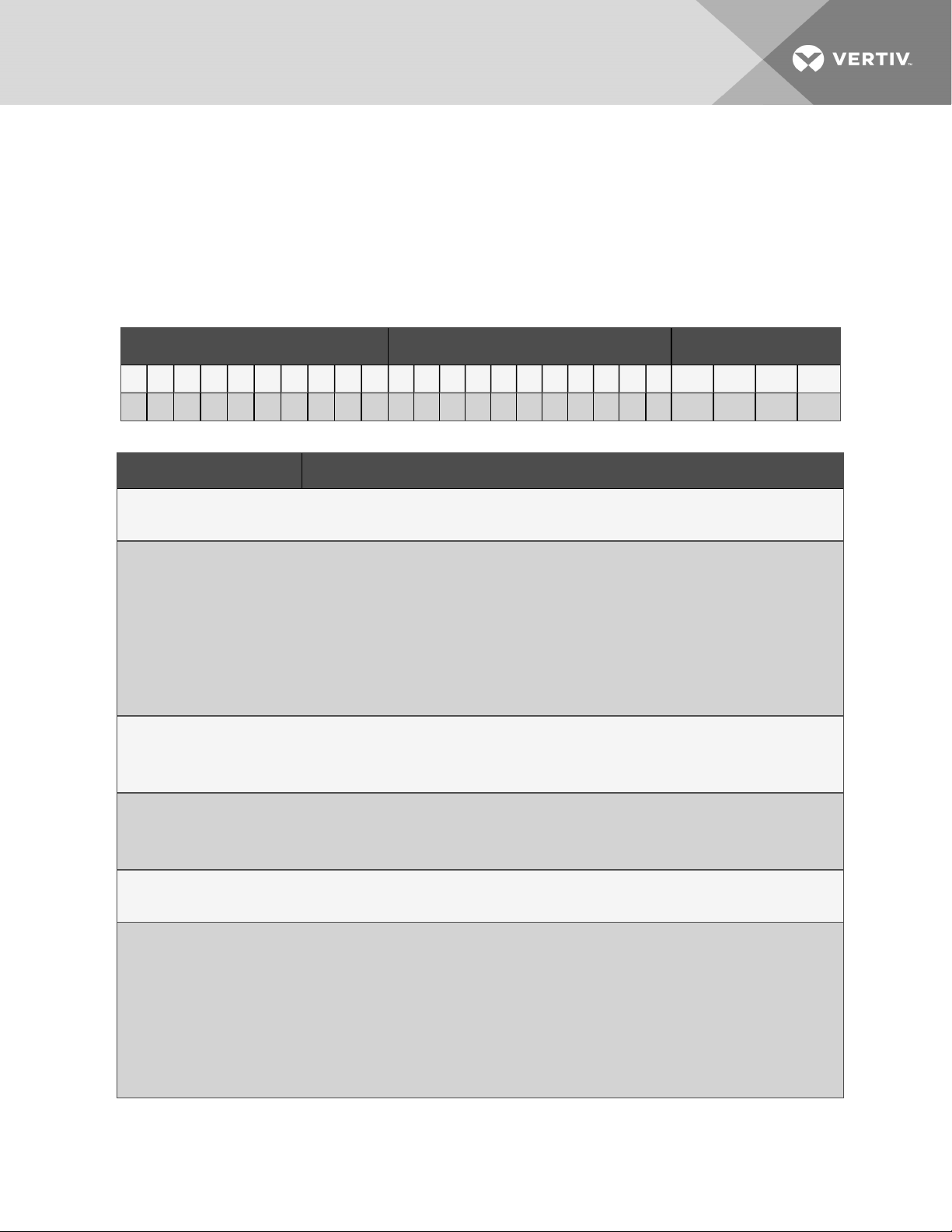
Table 1.1 DSE Model Number Example
ModelNumber Digits 1 to 10 ModelDetails ModelNumber Digits 11 to 14
1 2 3 4 5 6 7 8 9 10 11 12 13 14 1 5 16 17 1 8 1 9 20 2 1 22 23 24 25
D A 1 2 5 D P 1 A T H 2 0 8 1 1 D 0 B S P 1 2 3 S
Table 1.2 DSE Model-number Digit Definitions
Digit Description
Digits 1 and 2 = Product Family
DA = Liebert® DSE
Digit3, 4, 5 = Nominal CoolingCapacity, kW
050 = 50 kW
080 = 80 kW
085 = 85 kW
125 = 125 kW
150 = 150 kW
165 = 165kW
Digit6 = Air Discharge
Digit7 = System Type
Digit8 = Air-flow (Fan Type)
Digit9 = Voltage
1 Nomenclature and Componen ts
D = Downflow
U = Upflow
A = Air-cooled
P = Air-cooled, Econ-O-Phase ready
1 = EC plug fans
A = 460V -3ph -60Hz
B = 575V - 3ph -60Hz
C = 208V -3ph - 60Hz
D = 230V -3ph - 60Hz
2 = 380 V -3ph - 60Hz
M = 380-415 V -3ph - 50Hz
9
Page 16
Table 1.2 DSE Model-number Digit Definitions (continued)
Digit Description
Digit10 = Cooling System
D = Digital scroll, R-410A
T = Tandem withdigital scroll, R-410A
Digit11 = Humidifier
0 = No humidifier
H = Infrared Humidifier
Digit12 = Display
2 = iCOM (High Definition)
Digit13 = Rehea t
0 = None
1 = Electric reheat, standard capacity
R = Electric reheat, reduced capacity
Digit14 = Air Filter
8 = MERV 8, 4-in.
9 = MERV 11 , 4-in.
A = MERV 13, 4-in.
6 = MERV 11 , 2-in. plus MERV 8 pre-filter, 2-in.
C = MERV 13, 2-in. plus MERV 8 pre-filter, 2-in.
Digit15 = Coil Option
1 = Non-coated coil, indoor unit
Digit16 = Enclosure Option
1 = Color standard
2 = Color optional
3 = Color standard and IBC/OSHPD bracing
4 = Coloroptional and IBC/OSHPD bracing
Digit17 = High-voltage option
L = Locking disconnect
5 = Locking disconnect, with condensate pump
Digit18 = Option packages
0 = None
L = Optionpackage #1 - low-voltage terminal package
H = Reheat and Humidifier lockout
R = Remote humidity contact
D = Optionpackage #1 plus remote humidifier lockout
E = Optionpackage #1 plus reheat/humidifier lockout plus remote contact
10
Vertiv | Liebert® D SE™ Installer/U ser Guide
Page 17
Table 1.2 DSE Model-number Digit Definitions (continued)
Digit Description
Digit19 = Monitoring
B = Base comms and connectivity
Digit20 = Sensors
0 = None
S = Smoke sensor
H = High-temperature sensor
F = Smoke and High-temperature sensors
C = Compressor-overload sensors
D = Compressor, smoke sensors
K = Compressor, high-temperature, smoke sensors
Digit21 = Packa ging
P = Domestic
C = Export
Digit22-24 = Factory Configuration Number
Digit25 = Configuration Code
A = No SFAs (Any alpha letter except S)
S = SFA
1.2 Component Location
The unit component locations are described in the submittal documents included in the Submittal Drawings on page127.
The following table lists the relevant documents by number and title.
Table 1.3 Component-location Drawings
Docu ment Number Title
DPN003452 Component Location, Typical, Downflow Models, DA050–DA165
DPN003451 Component Location, Typical, Upflow Models, DA080–DA085
1 Nomenclature and Componen ts
11
Page 18

This page intentionally left blank
12
Vertiv | Liebert® D SE™ Installer/U ser Guide
Page 19

2 PRE-INSTALLATION PREPARATIONANDGUIDELINES
NOTE: Before installing unit, determine whether any building alterations are required to run piping, wiring and duct
work. Follow all unit dimensional drawings and refer to the submittal engineering dimensional drawings of individual
units for proper clearances.
Refer to Table 1.2 on page9, and submittal drawings to determine the type of system being installed and anticipate
building alterations, piping and duct work needed.
The unit dimensions, pipe-connection locations, and piping schematics are described in the submittal documents included
in the Submittal Drawings on page127.
• Verify that the floor is level, solid and sufficient to support the unit. See 2.6 on page19 for unit weights.
• Confirm that the room is properly insulated and has a sealed vapor barrier.
• For proper humidity control, keep outside or fresh air to an absolute minimum (less than 5% of total air
circulated in the room).
• Do not install a Liebert® DSE in an alcove or at the end of a long, narrow room.
• Install the units as close as possible to the largest heat load.
• Allow at least the minimum recommended clearances for maintenance and service. See the appropriate
submittal drawings for dimensions.
We recommend installing an under-floor water detection system. Contact your Vertiv representative for information.
2 Pre-inst allation Pr eparationan dGuidelines
13
Page 20
2.1 Planning Dimensions
The unit, floor stand, and plenum dimensions are described in the submittal documents included in the Submittal Drawings
on page127.
The following table lists the relevant documents by number and title.
Table 2.1 Dimension Planning Drawings
Docu ment Number Title
Downflow Units
DPN003533 Cabinet Dimensional Data, DA050
DPN004083 Cabinet Dimensional Data, DA080 and DA085
DPN003175 Cabinet andPlenum Dimensional Data, DA125, DA150 and DA165
UpflowUnits
DPN002950 Cabinet Dimensional Data, DA080U and DA085U
Floor Stands
DPN004079 Floorstand Dimensional Data, Downflow, DA050
DPN004073 Floorstand Dimensional Data, Downflow and Upflow, DA080 and DA085
DPN003177 Floorstand Dimensional Data, Downflow, DA125, DA150 and DA165
Plenums
DPN003514 Plenum Dimensional Data, Downflow, DA050, DA080 and DA085
DPN004081 Plenum Dimensional Data, Upflow, DA080U and DA085U
2.2 Air-distribution Considerations for Downflow Units
• Verify that the raised floor has been properly sized for the unit’s airflow and the room is free of airflow
restrictions.
• Perforated floor tiles in the raised floor should ensure minimal pressure loss.
• The raised floor must provide 7-1/2in. (191mm) of clearance.
• A minimum of 24in. (610mm) is required to operate the fans when they are lowered with the factory-provided
jacking mechanism.
• Ensure that there is adequate clearance above the unit for service, such as replacing filters.
• Optional plenums are available for downflow unit ducting.
14
Vertiv | Liebert® D SE™ Installer/U ser Guide
Page 21

Figure 2.1 Downflow unit field-installed ducting and plenum ducting for DA125, DA150 and DA165
2 Pre-inst allation Pr eparationan dGuidelines
15
Page 22
2.3 Air-distribution Considerations for Upflow Units
For in-room applications with supply and return grilles, several feet of clearance must be maintained at the intake and
discharge of the unit.
NOTE: Drain traps are qualified to a return duct static of negative 1.5 i.w.g. (-1.5i.w.g).
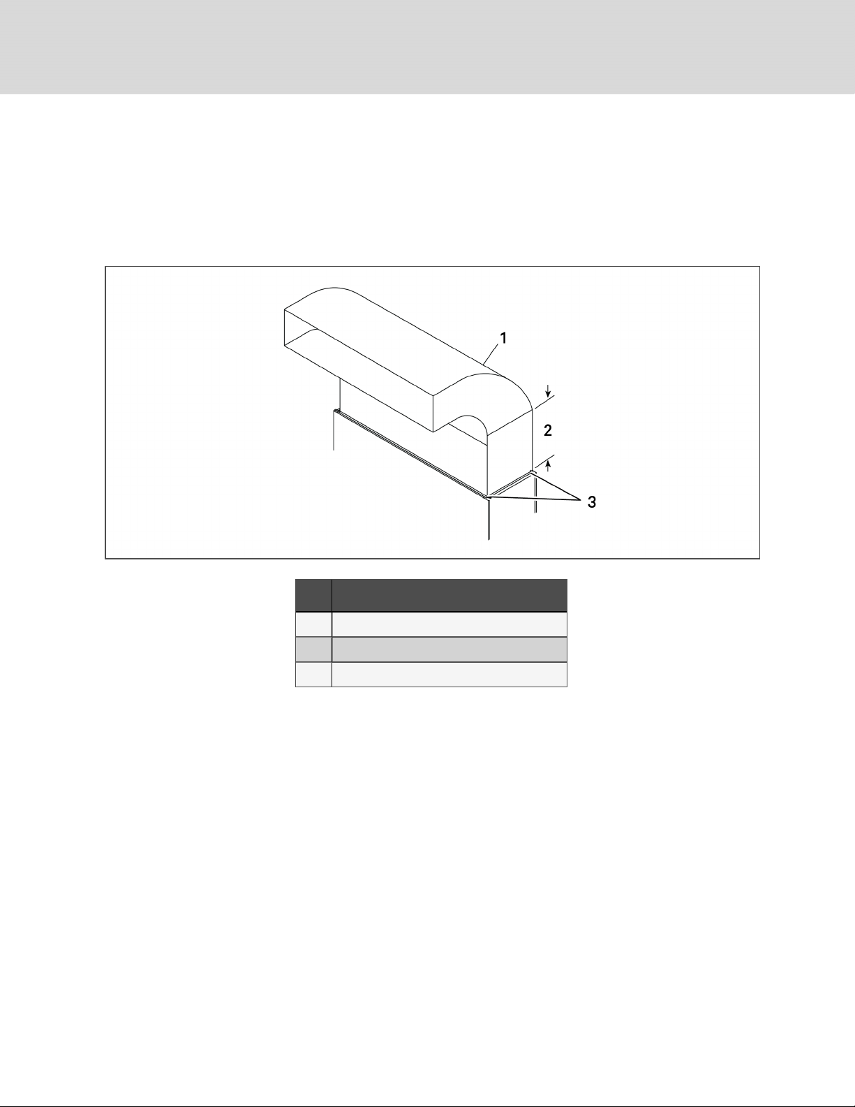
Figure 2.2 Upflow ducting configurations for EC fans for DA080 and DA085
Item Description
1 Typical ducting. May run to either side.
2 Straight section must be 2.5 times the depthof blower.
3 Ducting only attached to flanges onprovidedplenum.
NOTE: Follow standard practices in all duct work.
2.4 Connections and System Setup
• Three-phase electrical service is required for all models. Electrical service must conform to national and local
electrical codes. See equipment nameplate for details.
• The unit requires a drain, which must comply with all applicable codes. See Field-installed, Gravity-fed Drain
Line Requirements on page31, for details.
• Plan the routing of wiring, piping and duct work to the unit. Refer to the appropriate piping connection location
drawings, piping schematics, and electrical-connection drawings for your system in Submittal Drawings on
page127.
• If seismic requirements apply, consult your Vertiv representative for information about a seismic-rated floor
stand.
NOTE: Seal openings around piping and electrical connection to prevent air leakage. Failure to do so could reduce the
unit’s cooling performance.
16
Vertiv | Liebert® D SE™ Installer/U ser Guide
Page 23
The DSE controls superheat with an electronic expansion valve (EEV). The EEV controller adjusts the orifice based on
suction pressure and temperature. The EEV control will drive the valve to maintain the superheat setpoint, set in the
Liebert® iCOM, using a Proportional, Integral, Derivative (PID) routine. The PID control values are set at the factory for most
applications. These default values PID will allow stable superheat control of the unit.
For DA080/085 the default PID values must be updated to special PID values when the condenser is installed at the same
level as the evaporator or +10 feet (3m) above the evaporator. The PID control values (both default and special) are noted
Table 2.2 below.
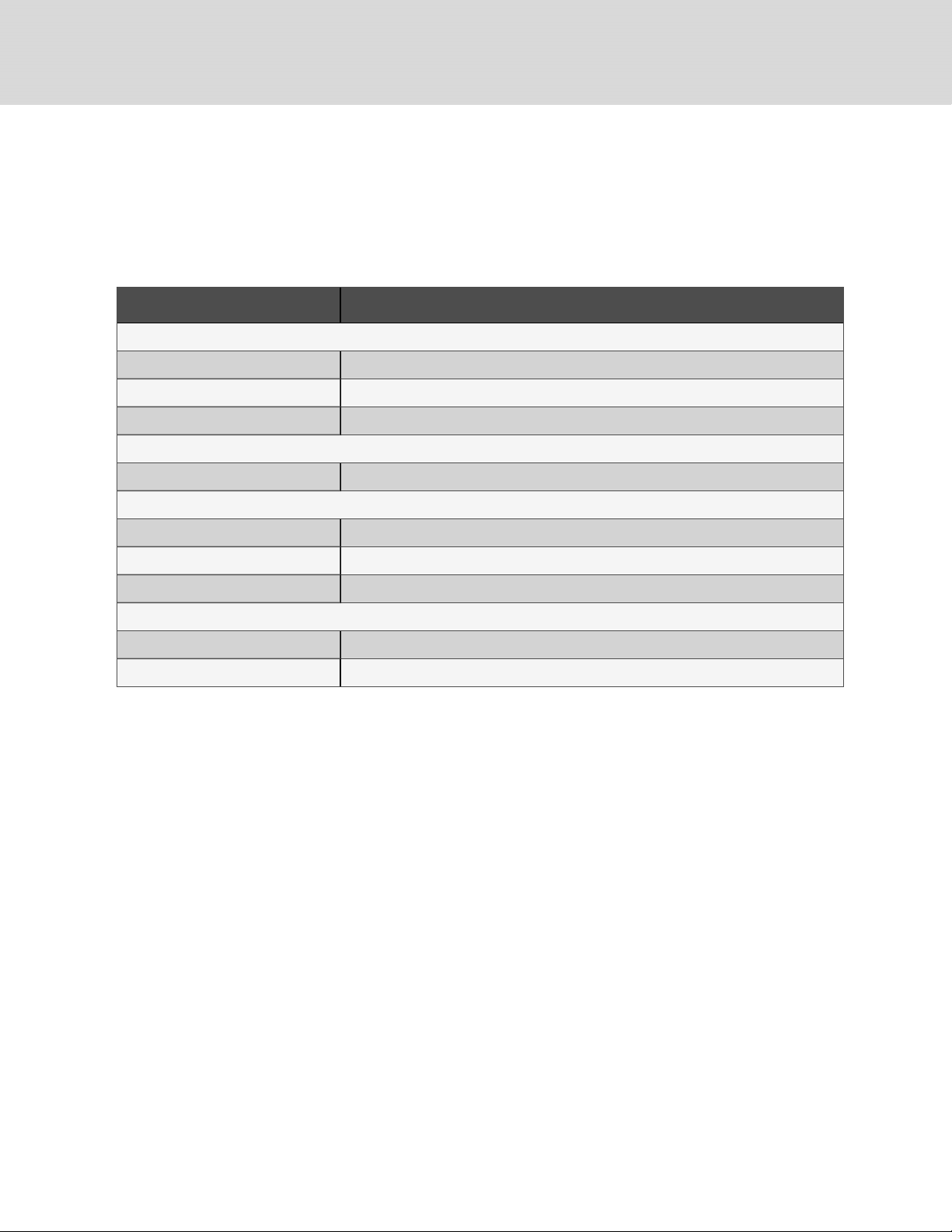
Table 2.2 EEV control values, default and special settings
EEV Settings
Model #
Default Values
(condenser and evaporator at same level ±10ft[3m])
Special Values
E144 = MAN
DA050
DA080/085
Downflow
Models
DA080/085
Upflow
Models
DA125/150
DA165
2.5 Operating Conditions
E160 = 0.6
E161 = 250
E162 = 1.0
E144 = MAN E144 = MAN
E160 = 0.7 E160 = 1.5
E161 = 250 E161 = 250
E162 = 4.2 E162 = 2.5
E144 = MAN
E160 = 2.5
E161 = 250
E162 = 4.2
E144 = MAN
E160 = 1.8
E161 = 250
E162 = 2.5
The Liebert® DSE must be operated in a conditioned space within the operating envelope that ASHRAE recommends for
data centers. Operating the DSE outside of this envelope can decrease equipment reliability. Refer to ASHRAE’s
publication, “Thermal Guidelines for Data Processing Environments.”
2.5.1 Cooling, Dehumidification and Humidification
The ASHRAErecommended maximum for return-air temperature is 105°F (40°C) and maximum dew point is 59°F (15°C).
The recommended minimum return-air temperature setpoint for the DSE is 75°F (24°C).
Operating outside this envelope can decrease equipment reliability.
NOTE: If running in supply-air control, the minimum supply-air setpoint is 64°F (18°C).
2 Pre-inst allation Pr eparationan dGuidelines
17
Page 24

DA050 Dehumidification Control
The DA050 is designed to maximize sensible cooling not latent cooling loads.
The room load must be at least 37.6kW (74% of unit capacity) to prevent over cooling the room at 85°F (29°C) return air
temperature while in dehumidification mode. If the room load is too low to maintain the setpoint, the compressor will cycle
On and Off. For rooms with multiple units, we recommend performing dehumidification via Teamwork mode to prevent
compressor cycling in case of lightly loaded rooms. Liebert® DSE units in dehumidification mode might not hold the
temperature setpoint unless there is sufficient room load. This will allow for better dehumidification of the room. The DSE
will allow the return air temperature to run down to 68°F (20°C) regardless of the temperature setpoint during
dehumidification mode of operation.
DA080 and DA085 Dehumidification Control
The DA080 and DA085 will run at lower evaporator temperatures than a DA125. This will result in a higher percentage of
latent cooling than with a DA125 at a given return air temperature. Dehumidification on DA080 and DA085 is possible with
only one circuit running. In dehumidification mode, with one circuit running, a single stage 15-kW electric reheat (customer
option) is available to help offset cooling for lightly loaded rooms, but over-cooling will be allowed down to 68°F (20°C). If
the unit is running in dehumidification mode with both circuits (compressors) running, the electric reheat is not available to
offset cooling.All DSE units allow the indoor blower to run at a reduced speed during dehumidification mode to increase the
amount of dehumidification being performed.
DA125 Dehumidification Control
The DA125 is designed to maximize sensible cooling not latent cooling loads. With all four compressors running, no reheat
will be available at this dehumidification load point (Stage 4).
The room load must be 94.1kW (74% of unit capacity) to prevent over-cooling the room at 85°F (29°C) return air
temperature. If the room load is too low to maintain the setpoint, the compressors will cycle On and Off. During Stage 3, with
three of the four compressors running, 10 kW of reheat will be available to offset cooling. During Stage 1 and 2, with one and
two compressors running respectively, 30 kW of reheat is available to offset cooling. For rooms with multiple units, We
recommend performing dehumidification in Teamwork mode to prevent compressor cycling in case of lightly loaded rooms
or by having standard DSE units available to perform dehumidification. DSE units in dehumidification mode might not hold
the temperature setpoint unless there is sufficient room load. This will allow for better dehumidification of the room. The DSE
will allow the return air temperature to run down to 68°F (20°C) regardless of the temperature setpoint during
dehumidification mode of operation.
DA150 and DA165 Dehumidification Control
The DA150 and DA165 are designed to maximize sensible cooling not latent cooling loads. With all four compressors
running, no reheat will be available at this dehumidification load point (Stage 4).
The room load must be 94.1kW (74% of unit capacity) to prevent over-cooling the room at 85°F (29°C) return air
temperature. If the room load is too low to maintain the setpoint, the compressors will cycle On and Off. During Stage 3, with
three of the four compressors running, 10 kW of reheat will be available to offset cooling. During Stage 1 and 2, with one and
two compressors running respectively, 30 kW of reheat is available to offset cooling. For rooms with multiple units, We
recommend performing dehumidification via Teamwork mode to prevent compressor cycling in case of lightly loaded
rooms. DSE units in dehumidification mode might not hold the temperature setpoint unless there is sufficient room load.
This will allow for better dehumidification of the room. The DSE will allow the return air temperature to run down to 68°F
(20°C) regardless of the temperature setpoint during dehumidification mode of operation.
18
Vertiv | Liebert® D SE™ Installer/U ser Guide
Page 25
2.5.2 Heating
The Liebert® DSE is qualified for heating-only operation at temperatures not exceeding 80°F (27°C).
2.5.3 Humidification Control
To prevent the humidifier from running when not required (especially when return air temperatures exceed 75°F [24°C]), the
default control for humidity and dehumidification is based on dew point temperature, not relative humidity. If this default
control is changed, adjust the relative humidity setpoint based on return air temperature to prevent from over-humidifying
the space.
2.6 Shipping Dimensions and Unit Weights
Table 2.3 Downflow unit domestic and export shipping dimensions and weights
Dom estic Packaging Export Packaging
Model #
Unit
Ship Weight, lb (kg)
Shippin g Dimensions, in. (mm) Sh ip Weight, lb (kg) Shipping Dimensions, in. (mm)
Dry Weight, lb (kg)
DA050*A
DA050*P
DA080*A
DA080*P
DA085*A
DA085*P
DA125*A
DA125*P
DA150*A
DA150*P
DA165*A
DA165*P
2012 (913)
2250 (1021)
2350 (1066)
3450 (1565)
3570 (1619)
3754 (1703)
97 X45 X 82
(2464X 1 143 X 2083)
120 X 45 X 85
(3048 X1143 X2159)
120 X 45 X 85
(3048 X 1143 X 2159)
153 X 54 X 85
(3886 X 1372 X 2159)
153 X 54 X 85
(3886 X 1372 X 2159)
153 X 54 X 85
(3886 X 1372 X 2159)
2182 (990)
2450(111 1)
2550 (1157)
3650 (1656)
3770 (1710 )
3954 (1794)
Table 2.4 Upflow unit domestic and export shipping dimensions and weights
Dom estic Packaging Export Packaging
Model #
Unit Ship Weight, lb (kg) Shipping dimensio ns, in. (mm) Ship Weight, lb (kg) Sh ipping dimensions, in.(m m)
97 X 45 X 82
(2464X 1 143 X 2083)
120 X 45 X85.5
(3048 X 1143 X2172)
120 X 45 X85.5
(3048 X 1143 X2172)
153. 5 X 54.5 X 85.5
(3899X 1384 X 2172)
153. 5 X 54.5 X 85.5
(3899X 1384 X 2172)
153. 5 X 54.5 X 83.5
(3899X 1384 X 2121)
1590( 721)
2200 (998)
2250 (1021)
3465 (1572)
3574 (1621)
3574 (1621)
Dry Weight, lb (kg)
DA080U*A
DA080U*P
DA085U*A
DA085U*P
2 Pre-inst allation Pr eparationan dGuidelines
2270 (1030)
2370 (1075)
120 X 45 X 85
(3048 X 1143 X 2159)
120 X 45 X 85
(3048 X 1143 X 2159)
2470 (1120)
2570 (11 66)
120 X 45 X85.5
(3048 X 1143 X 2172)
120 X 45 X85.5
(3048 X 1143 X 2172)
2150 (975)
2150 (975)
19
Page 26

This page intentionally left blank
20
Vertiv | Liebert® D SE™ Installer/U ser Guide
Page 27
3 EQUIPMENT INSPECTION AND HANDLING
SAFETY INFORMATION
WARNING! Risk of top-heavy unit falling over. Improper handling can cause equipment damage, injury or
death. Read all of the following instructions and verify that all lifting and moving equipment is rated for the
weight of the unit before attempting to move, lift, remove packaging from or prepare the unit for installation.
Unit weights are specified in Shipping Dimensions and Unit Weights on page19.
WARNING! Risk of improper moving. Can cause equipment damage, injury or death. Use only lifting
equipment that is rated for the unit weight by an OSHA-certified rating organization. The center of gravity
varies depending on the unit size and selected options. The slings must be equally spaced on either side of
the center of gravity indicator.
Shipping weights and unit weights are listed in the tables in Shipping Dimensions and Unit Weights on
page19. Use the center of gravity indicators on the unit to determine the position of the slings.
CAUTION: Risk of contact with sharp edges, splinters, and exposed fasteners. Can cause injury. Only
properly trained and qualified personnel wearing appropriate, OSHA-approved PPE should attempt to move,
lift, remove packaging from or prepare the unit for installation.
NOTICE
Risk of passageway interference. Can cause unit and/or structure damage. The unit may be too large to fit
through a passageway while on or off the skid. Measure the unit and passageway dimensions, and refer to the
installation plans prior to moving the unit to verify clearances.
NOTICE
Risk of damage from forklift. Can cause unit damage. Keep tines of the forklift level and at a height suitable to
fit below the skid and/or unit to prevent exterior and/or underside damage.
NOTICE
Risk of improper storage. Keep the unit upright, indoors and protected from dampness, freezing temperatures
and contact damage.
Upon arrival of the unit and before unpacking:
• Verify that the labeled equipment matches the bill of lading.
• Carefully inspect all items for visible or concealed damage.
• Report damage immediately to the carrier and file a damage claim with a copy sent to Vertiv or to your sales
representative.
3 Equipmen t Ins pection an d Hand ling
21
Page 28
Equipment Recommended for Handling the Unit:
• Forklift
• Pallet jack
• Piano jacks
• Lift beam
• Slings
• Spreader bars
3.1 Packaging Material
All material used to package this unit is recyclable. Please save for future use or dispose of the material appropriately.
3.2 Handling the Unit while Packaged
If possible, transport the unit with a forklift or pallet jack. If that is not possible, use a crane with slings and spreader bars
that are rated for the weight of the unit.
When using a forklift or pallet jack:
• Ensure that the fork length is suitable for the unit length and, if adjustable, spread to the widest allowable
distance that will fit under the skid.
• When moving the packaged unit, lift the unit from the "HEAVY SIDE" of the unit, and do not lift the unit any
higher than 6in.(152mm). All personnel except those moving the unit must be kept or more from the unit while
it is being moved.
• If the unit must be lifted higher than 6in.(152mm), all personnel not directly involved in moving the unit must
be 20ft (5m) or farther from the unit.
• Always refer to the location of the center-of-gravity indicators when lifting the unit, see Figure 3.1 below.
Figure 3.1 Center-of-gravity indicator
22
Vertiv | Liebert® D SE™ Installer/U ser Guide
Page 29
3.3 Unpacking the Unit
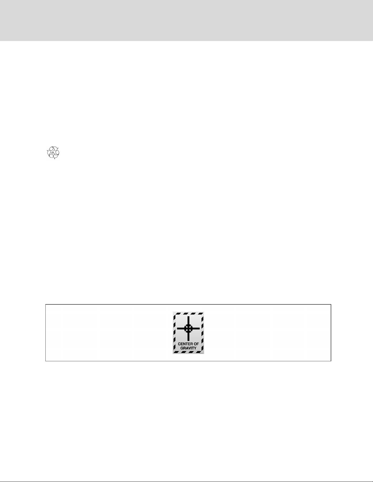
1. Remove the exterior stretch wrap packaging and two V-shaped boards from around the unit, as shown in Figure
3.2 below.
NOTE: The bag may remain in place to protect from dust and to protect the unit panels, or it may be removed for
immediate installation.
2. Remove the bag from the unit when ready to remove the skid and install the unit.
Figure 3.2 Unpacking the Unit
Item Description
1 Rem ove exterior wrap from unit
2 Remove corner and side packaging planks
3 Leave the bag on the unit until ready to install.
3.3.1 Removing the Unit from the Skid with a Forklift
Refer to Figure 3.3 on the next page.
1. Align a forklift with either the front or rear side of the unit.
• Ensure that the tines of the fork lift are locked to the widest location.
• Use the center of gravity indicators on the unit panels when determining the entry points for the tines.
Center of gravity varies per unit size and selected options.
• The tines shall be equally spaced on either side of the center of gravity indicator.
2. Insert the tines of the forklift completely under the base of the unit.
• Ensure that the tines are level, not angled in an upward direction.
• The tines are to be at a height that will allow proper clearance under the unit.
• Ensure that the tines extend beyond the opposite side of the unit.
NOTE: If these steps are not followed, damage may occur to the panels and/or base of the unit.
3 Equipmen t Ins pection an d Hand ling
23
Page 30
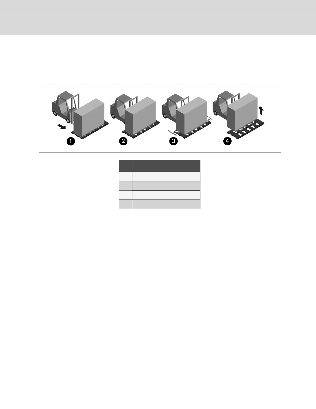
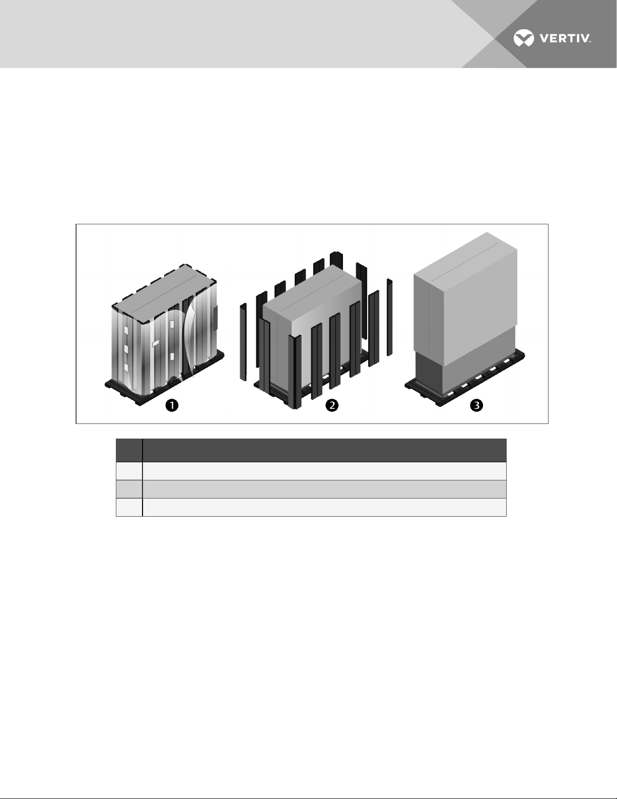
3. Remove the lag bolts from each bracket located around the base, and remove the brackets.
4. Lift the unit off the skid to an elevation point where the skid is not supporting the weight of the unit and remove
the skid from under the unit.
Figure 3.3 Removing from skid with a forklift
Item Description
1 Align forklift with frontor rear of unit.
2 Insert tines completely under base of unit.
3 Remove lag boltsand brackets
4 Lift unit and remove skid.
3.3.2 Removing the Unit from theSkid Using Rigging
1. Use the center-of-gravity indicators on the unit panels to determine the position of the slings.
• The slings shall be equally-spaced on either side of the center-of-gravity indicator
2. Place the slings and between the bottom rails of the unit and the skid as shown in Figure 3.4 on the facing
page.
NOTE: Unit is shown without packaging. These instructions may be followed with or without the outer packaging in
place.
24
Vertiv | Liebert® D SE™ Installer/U ser Guide
Page 31

Figure 3.4 Example sling placement
Item Description
1 Distance between sling and center-of-gravity marker equal to item2.
2 Distance between sling and center-of-gravity marker equal to item1.
3 Equipmen t Ins pection an d Hand ling
25
Page 32

3. Referring to Figure 3.5 below:
• Align the slings as described previously.
• Use spreader bars or equivalent device to ensure proper protection of the unit (Item 1).
• Remove the lag bolts from each bracket located around the base, and remove the brackets (Item 2).
NOTE: Depending on final installation location, the skid may need to remain under the unit. Therefore, the lag bolts
and brackets would not yet be removed.
• Lift the unit off the skid to an elevation point where the skid is not supporting the weight of the unit and
remove the skid from under the unit (Item 3).
Figure 3.5 Moving unit with rigging
Item Description
1 Spreader bars and rigging on unit.
2 Remove lag bolts andbrackets.
3 Lift the unit and remov e the skid.
3.3.3 Moving the Unit to the Installation Location Using Piano Jacks
Refer to Figure 3.6 on the facing page.
1. With the unit elevated, position piano jacks at each end of the unit.
2. Lower the unit to a height suitable for the piano jacks, place protective material between the unit and the piano
jacks and straps.
26
Vertiv | Liebert® D SE™ Installer/U ser Guide
Page 33

3. With the unit secured to the piano jacks, move the forklift away from the unit.
4. Using the piano jacks, at least two trained personnel can move the unit to the site for installation.
• For location considerations, refer to Pre-installation PreparationandGuidelines on page13.
Figure 3.6 Moving unit with piano jacks
Item Description
1 Place piano jacks on each end of the unit.
2 Use padding between unit and straps and, with the unit secured to the piano jacks, move the forklift away from the unit.
3 Equipmen t Ins pection an d Hand ling
27
Page 34

3.4 Placing the Unit on a Floor Stand
Refer to the floor-stand installation sheet, located inside the floor-stand package. Lower the unit onto the floor stand. Refer to
Figure 3.7 below. Be sure to align the welded tabs on top of the floor stand with the inside of the unit frame base.
NOTE: The floor stand for the units equipped with EC fans is not symmetrical. Its orientation to the unit is critical for
lowering the EC fans. Unless the floor stand is installed in the correct position, the fans will not lower into the floor
stand.
Figure 3.7 Welded tabs on floor stand
Item Description
1 Front of unit
28
Vertiv | Liebert® D SE™ Installer/U ser Guide
Page 35

4 PIPING AND REFRIGERANT REQUIREMENTS
All fluid and refrigeration connections to the unit, with the exception of the condensate drain, are sweat copper. Factoryinstalled piping brackets must not be removed. Field-installed piping must be installed in accordance with local codes and
must be properly assembled, supported, isolated and insulated. Avoid piping runs through noise-sensitive areas, such as
office walls and conference rooms.
Refer to specific text and detailed diagrams in this manual for other unit-specific piping requirements.
All piping below the elevated floor must be located so that it offers the least resistance to air flow. Careful planning of the
piping layout under the raised floor is required to prevent the air flow from being blocked. When installing piping on the
subfloor, we recommend that the pipes be mounted in a horizontal plane rather than stacked one above the other. Whenever
possible, the pipes should be run parallel to the air flow.
The following pipe connections are required:
• A drain line from the unit.
• A drain line from the secondary drain pan (if applicable).
• A water-supply line to the optional humidifier (if applicable).
• Refrigerant piping connections between the evaporator unit, the condensing unit, and the optional economizer
unit. See Refrigerant Piping and Charging on page34.
The pipe connection locations, piping general arrangement and schematics are described in the submittal documents
included in the Submittal Drawings on page127.
The following tables list the relevant documents by number and title.
Table 4.1 Piping General-arrangment Drawings
Docu ment Number Title
DPN002615 Piping Schematic, DA050, DA080 and DA085 with MC Condenser
DPN002340 Piping Schematic, DA125, DA150 and DA165 withMC Condenser
DPN004476 Piping Schematic, DA125, DA150 and DA165 with MCV Condenser
Liebert®MCCondenser and EconoPhase Pump Locations
DPN003994 Considerationsfor mounting MC Condenser/EconoPhase Above or at Same Level as DSE
DPN003552 Typical arrangement for single-circuit system
DPN002324 Typical arrangement for dual-circuit system
4 Piping an d Refrigerant Requirements
29
Page 36

Table 4.2 Piping Connection Drawings
Docu ment Number Title
Downflow Units
DPN003531 Connection Locations, DA050
DPN004080 Connection Locations, DA080 and DA085
DPN002312 Connection Locations, DA125
DPN004037 Connection Locations, DA150 and DA165
UpflowUnits
DPN002951 Connection Locations, DA080U and DA085U
4.1 Drain and Humidifier Fluid Piping
NOTICE
Risk of water leakage. Can cause severe property damage and loss of critical data center equipment.
The Liebert®DSE requires a water drain connection. Improper installation, application and service practices
can result in water leakage from the unit.
Do not locate the unit directly above any equipment that could sustain water damage.
We recommend installing monitored leak detection equipment for the water supply lines and the internal unit
water lines.
30
Vertiv | Liebert® D SE™ Installer/U ser Guide
Page 37

4.1.1 Field-installed, Gravity-fed Drain Line Requirements
NOTICE
Risk of water backing up in the drain line. Leaking and overflowing water can cause equipment and building
damage.
Do not install an external trap in the drain line. This line already has a factory-installed trap inside the cabinet.
Installation of a second trap will prevent drain-water flow and will cause the water to overflow the drain pan.
Sagging condensate drain lines may inadvertently create an external trap.
A 3/4-in. NPT-Female drain connection is provided on DA050 to DA085 units without an optional condensate pump. A 11/8in. NPT-Female drain connection is provided on DA125 to DA165 units without an optional condensate pump.
Observe the following requirements and refer to Figure 4.1 on the next page, when installing and routing the drain line:
• The drain line must be sized for 2 gpm (7.6 l/m) flow.
• The drain line must be located so it will not be exposed to freezing temperatures.
• The drain should be the full size of the drain connection.
• The drain line must slope continuously away from the unit. Pitch drain line toward drain a minimum of 1/8in.
(3mm) per 1ft (305mm) of length.
• Drain is trapped internally. Do not externally-trap the drain line.
• The drain line must be rigid enough that it does not sag between supports, which unintentionally creates traps.
• The drain line must comply with all applicable codes.
• On units with the optional, factory-installed condensate pump, see Factory-installed Condensate Pump on
page33 and Condensate-pump Drain Line Requirements on page33.
4 Piping an d Refrigerant Requirements
31
Page 38

Figure 4.1 Correct and Incorrect gravity drains for downflow and upflow units
Table 4.3 Gravity-fed Drain Line Figure Descriptions
Item Description
1 For downflow units
2 For upflow units
3 Correct drain installation
4 Incorrect drain installation
5 Internal drain
6 External drain
7 Continuous downward slope
32
Vertiv | Liebert® D SE™ Installer/U ser Guide
Page 39

Table 4.3 Gravity-fed Drain Line Figure Descriptions (continued)
Item Description
8 External trap. Do not trap externally.
9 External traps, although unintentional. Lines must be rigid enough not to bowover top of other objects.
10 Internal drain
11 DSEunit
4.1.2 Condensate-pump Drain Line Requirements
NOTICE
Risk of water backing up in the drain line. Leaking and overflowing water can cause equipment and building
damage.
Do not install an external trap in the drain line. This line already has a factory-installed trap inside the cabinet.
Installation of a second trap will prevent drain-water flow and will cause the water to overflow the drain pan.
Sagging condensate drain lines may inadvertently create an external trap.
Observe the following requirements when installing and routing the drain line:
• The drain line must be located so it will not be exposed to freezing temperatures.
• Size the piping based on the available condensate head.
• Drain is trapped internally. Do not externally-trap the drain line.
• The drain line must be rigid enough that it does not sag between supports, which unintentionally creates traps.
• We recommend installing monitored, under-floor leak-detection equipment.
Factory-installed Condensate Pump
If your unit includes an optional condensate pump, the pump is factory-installed inside the unit and a 1/2-in. copper sweat
connection is provided on the unit.
4.1.3 Water Supply-line Requirements for the Optional Humidifier
The unit may have an optional humidifier. Refer to the appropriate supply-line piping requirements if a humidifier is
included on your unit:
Infrared Humidifier:
• 1/4-in. supply line, maximum water pressure is 150 psi (1034kPa).
• Size supply line for 1 gpm (3.8 l/m), with a minimum water pressure of 20psi(138kPa).
• Do not supply de-ionized water to the humidifier.
4 Piping an d Refrigerant Requirements
33
Page 40

4.2 Refrigerant Piping and Charging
WARNING! Risk of over-pressurization of the refrigeration system. Can cause explosive discharge of highpressure refrigerant, loss of refrigerant, environmental pollution, equipment damage, injury, or death. This
unit contains fluids and gases under high pressure. Use extreme caution when charging the refrigerant
system. Do not pressurize the system higher than the design pressure marked on the unit's nameplate. For
systems requiring EU CE compliance (50Hz), the system installer must provide and install a pressure relief
valve in the high side refrigerant circuit that is rated same as the refrigerant high side “Max Allowable
Pressure” rating that is marked on the unit serial tag. Do not install a shutoff valve between the compressor
and the field installed relief valve. The pressure relief valve must be CE-certified to the EU Pressure
Equipment Directive by an EU “Notified Body.”
CAUTION: Risk of excessive refrigerant line pressure. Can cause tubing and component rupture resulting in
equipment damage and personal injury. Do not close off the refrigerant-line isolation valve for repairs unless
a pressure-relief valve is field- installed in the line between the isolation valve and the check valve. The
pressure-relief valve must be rated 5% to 10% higher than the system-design pressure. An increase in
ambient temperature can cause the pressure of the isolated refrigerant to rise and exceed the system-design
pressure rating (marked on the unit nameplate).
Consult local building and plumbing codes for installation requirements of additional pressure-relief devices when isolation
valves are field installed. Do not isolate any refrigerant circuits from over-pressurization protection.
NOTICE
NOTICE
Risk of oil contamination with water. Can cause equipment damage.
Liebert®DSE systems require the use of POE (polyolester) oil. POE oil absorbs water at a much faster rate
when exposed to air than previously used oils. Because water is the enemy of a reliable refrigeration system,
extreme care must be used when opening systems during installation or service. If water is absorbed into the
POE oil, it will not be easily removed and will not be removed through the normal evacuation process. If the oil
is too wet, it may require an oil change. POE oils also have a property that makes them act as a solvent in a
refrigeration system. Maintaining system cleanliness is extremely important because the oil will tend to bring
any foreign matter back to the compressor.
Risk of improper refrigerant charging. Can cause equipment damage.
Refrigerant charge must be weighed into air-cooled compressorized systems before they are started. Starting
scroll and digital scroll compressors without proper refrigerant charging can cause the compressors to operate
at less than 5°F (–15°C) evaporator temperature and at less than 52psig(358kPa). Operation for extended
periods at less than 52psig(358kPa) can cause premature compressor failure.
34
Vertiv | Liebert® D SE™ Installer/U ser Guide
Page 41

4.2.1 Refrigerant Piping Guidelines forAir-cooledSystems
• Air-cooled units ship with a nitrogen holding charge. Do not vent the charge until all refrigerant piping is in
place, ready for connection to the unit and condenser.
• Use copper piping with a brazing alloy with a minimum temperature of 1350°F (732°C), such as Sil-Fos. Avoid
soft solders, such as 50/50 or 95/5.
• Use a flow of dry nitrogen through the piping during brazing to prevent formation of copper oxide scale inside
the piping. When copper is heated in the presence of air, copper oxide forms. POE oils will dissolve these
oxides from inside the copper pipes and deposit them throughout the system, clogging filter driers and
affecting other system components.
• A pure dry nitrogen flow of 1-3 ft3/min (0.5-1.5 l/s) inside the pipe during brazing is sufficient to displace the air.
Control the flow using a suitable measuring device.
• Ensure that the tubing surfaces to be brazed are clean and that all burrs have been removed from the ends of
the tubes.
• Ensure that all loose material has been cleaned from inside the tubing before brazing.
• Protect all refrigerant line components within 18in. (460mm) of the brazing site by wrapping them with a wet
cloth or with a suitable heat-sink compound.
• Isolate piping from building using vibration-isolating supports.
• Condensers with receivers cannot be installed below the evaporator. The maximum height of the condenser
above the evaporator is 60ft (18.3m).
Consult the factory before installing units, condensers, and receivers outside these parameters.
• Consult factory if piping run exceeds 300ft (91m) actual length or 450ft(137.2m) equivalent length.
• Install traps on hot-gas (discharge) lines at the base of vertical risers over 5ft(1.5m) and then for vertical rises
over 25 ft (7.6m), install a trap in 20-ft (6-m) increments or evenly-divided over the vertical rise.
• Pitch horizontal hot-gas piping down at a minimum rate of 1/2in.per 10ft (42mm per 10m) so that gravity will
aid in moving oil in the direction of refrigerant/oil flow.
• Keep piping clean and dry, especially on units with R-410A refrigerant.
• Avoid piping runs through noise-sensitive areas.
• Do not run piping directly in front of discharge air stream.
• Refrigerant oil – do not mix oil types (see Compressor Oil on page102).
Refer to ASHRAE Refrigeration Handbook for general, good-practice refrigeration piping. The indoor cooling unit has a
factory-installed high-pressure safety switch in the high side refrigerant circuit. A fusible plug is installed in each Liebert®
DSE receiver.
NOTE: All indoor and outdoor field refrigerant piping must be insulated 1/2 in. minimum. All outdoor insulation must
be UV and ozone resistant.
• Refer to Refrigerant Line Sizes and Equivalent Lengths on the next page, for recommended refrigerant piping
sizes based on equivalent pipe lengths.
• Refer to Refrigerant Charge Requirements for Air-cooled Systems on the next page, for the refrigerant-charge
requirements of the system.
• Refer to Charging Air-cooled Systems on page41, for charging information.
4 Piping an d Refrigerant Requirements
35
Page 42

4.2.2 Refrigerant Line Sizes and Equivalent Lengths
Table 4.4 Recommended Refrigerant Line Sizes, OD Copper
Model DA050 DA080 and DA085 DA125 DA150 and DA165
Equivalent
Length
Hot Gas L ine,
in.
Liquid Lin e,
in.
Hot Gas L ine,
in.
Liquid Lin e,
in.
Hot Gas L ine,
in.
Liquid Lin e,
in.
Hot Gas L ine,
in.
Liquid Lin e,
in.
50 ft (15 m) 1-1/8 7/8 1-1/8 7/8 1-3/8 7/8 1-3/8 7/8
100 ft (30 m) 1-1/8 7/8 1-1/8 7/8 1 -3/8 7/8 1-3/8 1-1/8
150 ft (45 m) 1-1/8 7/8 1-1/8 7/8 1 -3/8 7/8 1-3/8 1-1/8
300 ft (91 m) 1-1/8 7/8 1-1/8 7/8 1-3/8 7/8 1-3/8 1-1/8
450 ft (137 m )* 1-1/8 7/8 1-1/8 7/8 1 -3/8 7/8 1-3/8 1-1/8
*Consult factory when actual pipe length between condenser/EconoPhase and Liebert DSE unit will exceed 300 ft (91 m).
Source: DPN000 788 Rev. 1 3
NOTE: Install a 1-3/8-in. liquid line between the receiver outlet on the condenser and the Liebert EconoPhase™ unit,
regardless of line sizes indicated in Table 4.4 above. See the piping schematics for your system in Submittal
Drawings on page127. For installations using pre-fabricated heat-rejection skids, included piping must be factored
into total equivalent length calculation. Please consult factory for details.
4.2.3 Refrigerant Charge Requirements for Air-cooled Systems
The following tables provide the refrigerant charge requirements for the Liebert® DSE, connected piping, and condenser
options.
Table 4.5 Indoor Unit Approximate Refrigerant Charge for R-410A Per Circuit
Indoo r Unit Type Model Circuit 1 (Outercircuit), lb(kg) Circuit 2 (Innercircuit), lb(kg)
DA050 11 (5) NA
DA080 16 (7.3) 14 (6.4)
DA085 18 (8.2) 16 (7.3)
Air-cooled
DA125 28 (12.7) 25 (11.3)
DA150 28 (12.7) 25 (11. 3)
DA165 28 (12.7) 25 (11.3)
*System Charge = indoor unit + condenser +refrigerant receiv er + refrigerant lines + EconoPhase (PRE).
For system charges over 200 lb. (90.7kg), consult your Vertiv representative.
See Table 9.3 on page102 for the recommended oil for the system.
36
Vertiv | Liebert® D SE™ Installer/U ser Guide
Page 43

Table 4.6 MC Condenser Refrigerant Charge for R-410A Per Circuit
Standard Condenser Model
Per circuit withSmallReceiver,
lb(kg)
MCM080E1 17.0 (7.7 ) —
MCL110E1 19.5 (8.8) —
MCL110E2 14.0 (6.4) —
MCM160E2 17 .0 (7. 7) 24.0 (10. 9)
MCL220E2 21.0 (9.5) 28.0 (12.7 )
MCL165E1 — 34.0 (15.4)
MCL220E1 — 42.5 (19.3)
Condenser charge includes receiv er.
Small Receiver: 28-in. long, usedon DA050, DA080 and DA085.
Large Receiver: 60-in. long, used on DA125, DA150 and DA165.
Table 4.7 MCV Heat-rejection Skid Approximate R-410A refrigerant required per circuit
Heat-rejection Skid* System # Circuit Number Charge per circuit, lb (kg)
MCV330 Single skid with (1) PRE unit 1
*The heat-rejection skid contains MCV condenser(s), DSEreceiver(s), EconoPhase (PRE) unit(s), and all internal piping.
1 52 (24.6)
2 52 (24.6)
Per circuit with LargeReceiver,
lb(kg)
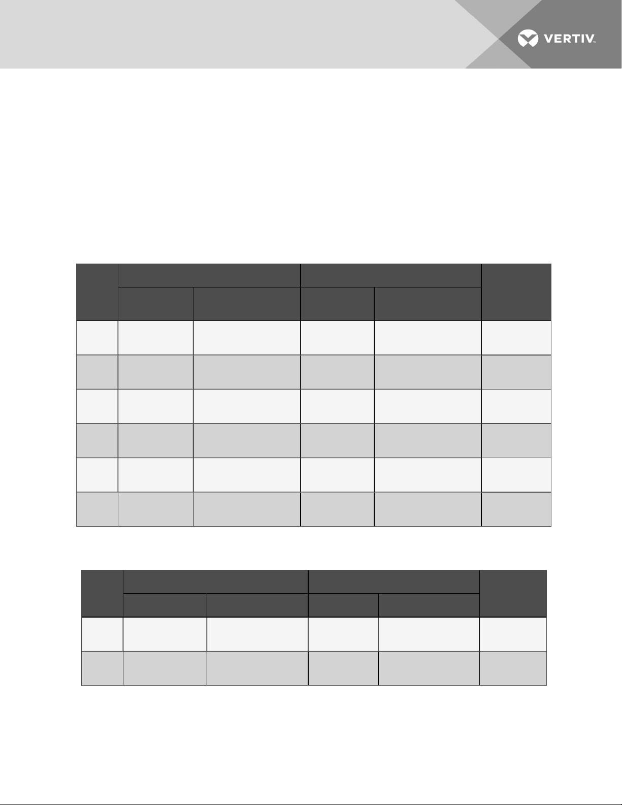
Table 4.8 Interconnecting Piping Refrigerant Charge for R-410A, lb per 100ft (kg per 30m)
Line Size, O.D ., in. Liquid Line Hot Gas Line
7/8 19.8 (8.8) 2.3 (1.0)
1-1/8 33.8 (15.1) 3.9 (1.7)
1-3/8 51.5 (23.0) 5.9 (2.6)
Source: DPN003099, Rev. 1
Table 4.9 Liebert Pump Module Refrigerant Charge forR-410APer Circuit
System Type Model Charge per Circuit, lb(kg)
PR125
Liebert®EconoPhase™ Pumping Unit
PR085
PR050
5.4 (2.5)
4 Piping an d Refrigerant Requirements
37
Page 44

4.2.4 Additional Oil Requirements forScrollandDigital-scrollCompressors
NOTICE
Risk of improper compressor lubrication. Can cause compressor and refrigerant system damage.
Failure to use oil types, viscosities and quantities recommended by the compressor manufacturer may reduce
compressor life and void the compressor warranty. See Table 9.3 on page102 for the recommended oil for
the system.
• Do not mix polyolester (POE) and mineral-based oils.
• Do not mix oils of different viscosities.
• Consult your Vertiv sales representative, visit https://www.Vertiv.com/en-us/support/, or contact the
compressor manufacturer if questions arise.
See Table 4.10 on the facing page, for the amount required for various system charge levels.
In addition to oil added based on system charge, additional oil is required for discharge-line field-installed traps. Standardformed tube traps are required, see Figure 4.2 below, and Table 4.11 on page40, because straight tubes and fittings
used as traps require much more oil and the length of the straight tube can vary.
After the system has been fully charged with refrigerant, use a hand pump to add the additional oil at the suction side of the
system while the system is running.
The amount of oil added by field service must be recorded on the tag marked “Oil Added Field Service Record,” attached
to each compressor. The date of oil addition must be included as well.
Figure 4.2 Standard-formed Tube Trap Versus Straight-tubes-and-fittings Trap
Item Description
1 Standard-formed tube trap
2 Straight tubes and fittings trap
38
Vertiv | Liebert® D SE™ Installer/U ser Guide
Page 45

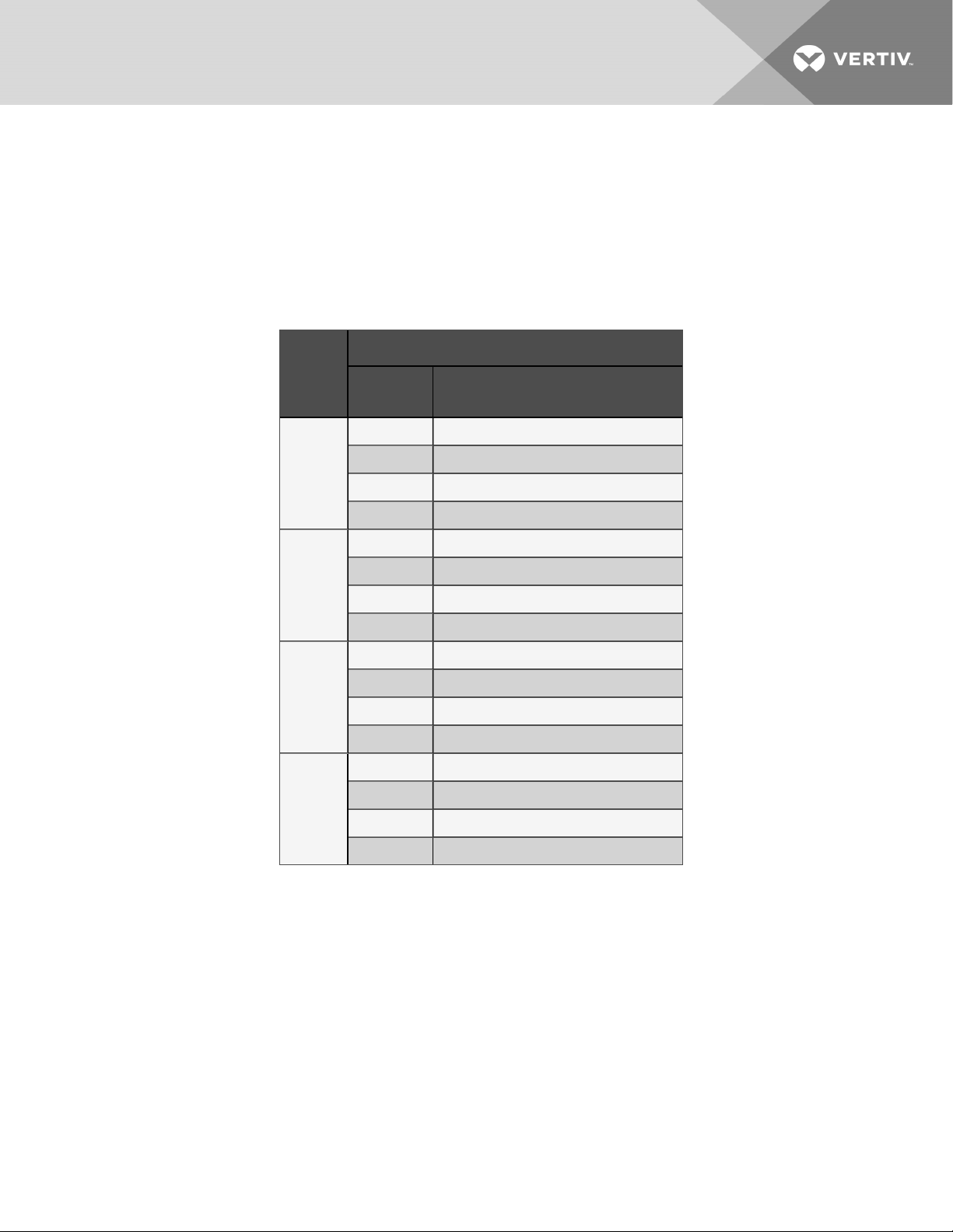
Table 4.10 Additional Oil Required per Refrigerant Charge
Model
Refrigerant System Charge
Per Circuit, lb (kg) *
DA050 DA080 DA085 DA125 DA150 DA165
Additional Oil Required Per Circuit, oz (ml)
< 40 (18.1) 0 0 0 0 0 0
40 (18.1) 5 (150) 5 (150) 5 (150) 0 1 0 (300) 10 (300)
50 (22.7) 9 (270) 9 (270) 9 (270) 4 (120) 18 (530) 18 (530)
60 (27.2) 13 (380) 13 (380) 13 (380) 8 (240) 26 (770) 26 (770)
70 (31.8) 17 (500) 17 (500) 17 (500) 11 (330) 34 (1010) 34 (1010)
80 (36.3) 21 (620) 21 (620) 21 (620) 14 (410) 42 (1240) 42 (1240)
90 (40.8) 25 (740) 25 (740) 25 (740) 1 7 (500) 50 (1480) 50 (1480)
100 (45.4) 29 (860) 29 (860) 29 (860) 20 (590) 58 (1720) 58 (1720)
110 (49.9) 33 (980) 33 (980) 33 (980) 23 (680) 66(1950) 66 (1950)
120 (54.4) 37 (1090) 37 (1090) 37 (1090) 26 (770) 74 (2190) 74 (2190)
130 (59.0) 41 (121 0) 41 (1210) 41 (121 0) 29 (860) 82 (2430) 82 (2430)
140 (63.5) 45 (1330) 45 (1330) 45 (1330) 32 (950) 90 (2660) 90 (2660)
150 (68.0) 49 (1450) 49 (1450) 49 (1450) 36 (1060) 98 (2900) 98 (2900)
160 (72.6) 53 (1570) 53 (1570) 53 (1570) 40 (1180) 106 (3130) 106 (3130)
170 (77.1 ) 57 (1690) 57 (1690) 57 (1690) 43 (1270) 11 4 (3370) 114 (3370)
180 (81.6) 61 (1800) 61 (1800) 61 (1800) 46 (1360) 122 (3610) 122 (3610)
190 (86.2) 65 (1920) 65 (1920) 65 (1920) 49 (1450) 1 30 (3840) 130 (3840)
200 (90.7) 69 (2040) 69 (2040) 69(2040) 52 (1540) 1 38 (4080) 138 (4080)
*System Charge = indoor unit + condenser +refrigerant receiv er + refrigerant lines.
For system charges over 200 lb. (90.7kg), consult your Vertiv representative.
See Table 9.3 on page102, , for the recommended oil for the system.
Source:DPN003950 Rev. 5
4 Piping an d Refrigerant Requirements
39
Page 46

Table 4.11 Volume of Oil in Standard-form Trap by Pipe Diameter
Pipe d iameter, in. Oil volume, oz (ml)
1/2 0.2 (5.9)
5/8 0.4 (11.8)
3/4 0.6 (17.7)
7/8 0.9 (26.6)
1-1/8 1.8 (53.2)
1-3/8 3.3 (97.6)
1-5/8 5.5 (162.7)
Source: DPN003950, Rev. 5
4.2.5 Evacuation, Leak-testing, and Charging Air-cooled Systems withReceivers
Two discharge lines and two liquid lines (one discharge line and one liquid line for DA050 models)must be field-installed
between the indoor unit and the outdoor condenser. See DPN002615 and DPN002340 in Submittal Drawings on page127.
for additional field-installed piping needed at the condenser.
NOTE: Keep the evaporator unit, EconoPhase, receiver, and condenser closed with their factory charge of dry
nitrogen while all field piping is installed. Keep the field piping clean and dry during installation. Do not allow it to
stand open to the atmosphere. When all the field interconnecting piping is in place, vent each outdoor unit’s dry
nitrogen charge and connect to the field piping. Finally, vent the evaporator unit's dry nitrogen charge and make its
piping connection last. Follow all proper brazing practices, including a dry nitrogen purge to maintain system
cleanliness. The condenser connection pipes must be wrapped with a wet cloth to keep the pressure and temperature
sensors cool during any brazing.
Evacuation and Leak-testing Air-cooled Systems
For proper leak-check and evacuation, you must open all system valves and account for all check valves.
NOTE: The system includes a factory-installed check valve and an additional downstream Schrader valve with core in
the compressor discharge line. Proper evacuation of the condenser side of the compressor can be accomplished only
using the downstream Schrader valve. See the appropriate piping schematic for your system in Submittal Drawings
on page127.
1. Starting with Circuit #1, open the service valves and place a 150 PSIG (1034kPa) of dry nitrogen with a tracer
of refrigerant. Check system for leaks with a suitable leak detector.
2. With pressure still in Circuit #1, open the compressor service valves in Circuit#2.
• If pressure increases in Circuit#2, the system is cross-circuited and must be re-checked for proper
piping.
• If there is no pressure increase, repeat step1 on Circuit#2.
3. After completion of leak testing, release the test pressure, (observe local code) and pull an initial deep vacuum
of 500microns on the system with a suitable pump.
4. After 4hours, check the pressure readings and, if they have not changed, break vacuum with dry nitrogen. Pull
a second and third vacuum to 500 microns or less. Re-check the pressure after 2hours.
When the 3 checks are complete, remove the jumper hose from the service-valve fitting and the condenser, and
proceed to Charging Air-cooled Systems on the facing page.
40
Vertiv | Liebert® D SE™ Installer/U ser Guide
Page 47

Charging Air-cooled Systems
NOTICE
Risk of improper refrigerant charging. Can cause equipment damage.
R-410A is a blended refrigerant and must be introduced and charged from the cylinder only as a liquid.
When adding liquid refrigerant to an operating system, it may be necessary to add the refrigerant through the
compressor suction service valve. Care must be exercised to avoid damage to the compressor. We recommend
connecting a sight glass between the charging hose and the compressor suction service valve. This will permit
adjustment of the cylinder hand valve so that liquid can leave the cylinder while allowing vapor to enter the
compressor.
NOTICE
Risk of improper operation. Can cause compressor failure.
Operating the unit with the EEV closed can cause compressor failure. The reheat and humidifier are disabled. A
minimum of 20 psig (138 kPa) must be established and maintained for the compressor to operate. The
charging function can be reset as many times as required to complete
To charge the system:
1. Check the nameplate on the indoor unit for refrigerant type to be used. Unit control configurations differ
depending on refrigerant type.
2. The unit must be operating during charging, refer to Checklist for Completed Installation on page77, the
"Liebert® MC™ Installer/User Guide," and "Liebert® EconoPhase™ Installer/User Guide."
3. Calculate the amount of charge for the system. See Refrigerant Charge Requirements for Air-cooled Systems
on page36.
4. Accurately weigh in as much of the system charge as possible before starting the unit. Do not exceed the
calculated charge by more than 0.5lb(0.37kg).
5. Close the Liebert® MC and Liebert® EconoPhase disconnect switches.
• We recommend charging the unit with the return-air setpoint between 75°F and 85°F (24°C and 29°C).
• The return-air temperature to the unit being charged must be stable and must be maintained greater
than 65°F(18°C). If this is not possible due to lack of heat load, then the load banks must be used to offset
the cooling load during start-up. See Target Refrigerant-level in Sight Glasses at Outdoor Temperatures
on the next page.
6. Close the Liebert® DSE disconnect switch.
7. In the Service menu of the Liebert® iCOM controller, select Diagnostics/Service > Diagnostics:
a. Enable Manual Mode.
NOTE: Manual Mode times-out after 30 minutes.
NOTE: You must establish and maintain a minimum 20psig (138kPa) for the compressor to operate.
4 Piping an d Refrigerant Requirements
b. In Evaporator Fan options set Motors to On to operate the fan during Manual Mode.
c. In Compressor Circuit 1 options, set Compressor Mode to Charge to operate the compressor at full
capacity, energize the blower motor, and open the EEV.
d. Reset the charge function as many times as needed to complete unit charging.
e. Repeat step 7 for Compressor Circuit 2.
41
Page 48

8. Check the refrigerant level in the refrigerant-level sight glasses on each receiver after the unit has been
operating for at least 15minutes.
NOTE: Each receiver at the condenser has 2 sight glasses and the refrigerant level varies with outside temperature.
9. Adjust the refrigerant level in each circuit to meet the level shown in Target Refrigerant-level in Sight Glasses
at Outdoor Temperatures below.
10. After adjusting the refrigerant, allow the system to operate an additional 15minutes before checking for the
need of further adjustment.
NOTE: A digital-scroll compressor can have a clear unit sight glass on the liquid line only when operating at 100%
capacity. When operating with a receiver, the unit sight glass might not become clear even when operating at 100%
capacity. When operating below 100%, the unit sight glass may show bubbles with each 15-second unloading cycle.
Target Refrigerant-level in Sight Glasses at Outdoor Temperatures
• 40°F (4.5°C) and lower—bottom sight glass is 3/4 full
• 40°F (4.5°C) and higher—bottom sight glass is full
If the return air temperature cannot be maintained between 75°F and 85°F (24°C and 29°C) due to lack of load, then the
liquid-level receiver must be adjusted to the following if return air is between 65°F and 75°F (18°C and 24°C):
• 40°F (4.5°C) and lower—Charge to the bottom of the top sight glass.
• 40°F (4.5°C) and higher—top sight glass is 1/4 full
42
Vertiv | Liebert® D SE™ Installer/U ser Guide
Page 49

5 ELECTRICAL CONNECTIONS
Three-phase electrical service is required for all models. Electrical service must conform to national and local electrical
codes. Refer to equipment nameplate regarding wire size and circuit protection requirements. Refer the appropriate
submittal drawing, listed in Electrical Field-connection Drawings on the next page, for electrical service entrances into unit
A manual electrical disconnect switch should be installed in accordance with local codes and distribution system. Consult
local codes for external disconnect requirements.
WARNING! Arc flash and electric shock hazard. Open all local and remote electric power-supply disconnect
switches, verify with a voltmeter that power is Off and wear appropriate, OSHA-approved personal protective
equipment (PPE) per NFPA 70E before working within the electric control enclosure. Failure to comply can
cause serious injury or death. Customer must provide earth ground to unit, per NEC, CEC and local codes, as
applicable. Before proceeding with installation, read all instructions, verify that all the parts are included and
check the nameplate to be sure the voltage matches available utility power. The Liebert® controller does not
isolate power from the unit, even in the “Unit Off” mode. Some internal components require and receive
power even during the “Unit Off” mode of the controller. The factory-supplied disconnect switch is inside the
unit. The line side of this switch contains live high-voltage. The only way to ensure that there is NO voltage
inside the unit is to install and open a remote disconnect switch. Refer to unit electrical schematic. Follow all
local codes.
WARNING! Risk of electric shock. Can cause equipment damage, injury or death. Open all local and remote
electric power supply disconnect switches and verify with a voltmeter that power is off before working within
any electric connection enclosures. Service and maintenance work must be performed only by properly
trained and qualified personnel and in accordance with applicable regulations and manufacturers’
specifications. Opening or removing the covers to any equipment may expose personnel to lethal voltages
within the unit even when it is apparently not operating and the input wiring is disconnected from the
electrical source.
5 Electrical Connections
WARNING! Risk of improper wire sizing/rating and loose electrical connections. Can cause overheated wire
and electrical connection terminals resulting in smoke, fire, equipment and building damage, injury or death.
Use correctly sized copper wire only and verify that all electrical connections are tight before turning power
On. Check all electrical connections periodically and tighten as necessary.
WARNING! Risk of wiring damage, short circuits and electric shock. Can cause overheated wiring, smoke, fire,
activation of fire suppression systems and EMS personnel and equipment, building and equipment damage,
injury or death. Insert CSA certified or UL listed bushings into holes and or knockouts used to route wiring
through metal panels to protect the wire insulation from contact with sheet metal edges.
43
Page 50

NOTICE
Risk of improper power-supply connection. Can cause equipment damage and loss of warranty coverage.
Prior to connecting any equipment to a main or alternate power source (for example: back-up generator
systems) for start-up, commissioning, testing, or normal operation, ensure that these sources are correctly
adjusted to the nameplate voltage and frequency of all equipment to be connected. In general, power-source
voltages should be stabilized and regulated to within ±10% of the load nameplate nominal voltage. Also, ensure
that no three-phase sources are single-phased at any time.
See transformer label for primary tap connections. Installer will need to change transformer primary taps if
applied unit voltage is other than pre-wired tap voltage.
NOTICE
Risk of improper electrical connection of three-phase input power. Can cause backward compressor rotation
and unit damage. Service technicians should use a gauge set on the system during the initial start up to verify
that the three-phase power is connected properly. The EC fans are not a reliable indicator of proper connection.
The blowers will rotate the same direction, regardless of the three-phase power input. Three-phase power must
be connected to the unit line voltage terminals in the proper sequence so that the compressors rotate in the
proper direction. Incoming power must be properly phased to prevent compressors from running backward.
We recommend checking the unit’s phasing with proper instrumentation to ensure that power connections were
made correctly. We also recommend verifying discharge and suction pressures during start up to ensure that
the compressors are running in the correct direction.
NOTE: Seal openings around piping and electrical connection to prevent air leakage. Failure to do so could reduce the
unit’s cooling performance.
The electrical and unit-to-unit connections are described in the submittal documents included in the Submittal Drawings on
page127.
The following tables list the relevant documents by number and title.
Table 5.1 Electrical Field-connection Drawings
Docu ment Number Title
DPN004387 Electrical Field Connections, Upflow & Downflow, DA050, DA080, and DA085 Models
DPN004388 Electrical Field Connections, DownflowModels, DA125, DA150, and DA165
DPN003284
DPN002361
DPN003886 CANbus cable connections between indoor unit, Liebert® MCVcondenser
Unit-to-Unit Networking
DPN004351 Liebert®iCOM Unit-to-unit Network Connections
CANbus cable connectionsbetween indoor unit, 1 Liebert®MCcondenser and optional Liebert®
EconoPhase pump
CANbus cable connectionsbetween indoor unit, 2 Liebert®MCcondensers and optional Liebert®
EconoPhase pump
44
Vertiv | Liebert® D SE™ Installer/U ser Guide
Page 51

6 EC FANS AND PLENUMS
Depending on the air-distribution options of your unit, you may have EC fans and/or plenums to install.
6.1 Downflow Units with EC Fans
DSE downflow models are equipped with EC fans that may operate in the fully-raised position or lowered into the floor stand
for increased efficiency from reduced air resistance.
WARNING! Risk of very heavy 125-lb (56.7-kg) fan modules dropping downward suddenly. Can cause injury or
death. Support fan modules before removing mounting hardware. Use caution to keep body parts out of the
fan modules pathway during repositioning. Only properly trained and qualified personnel should work on
this equipment.
CAUTION: Risk of improper handling of heavy and lengthy parts. Can cause personal injury and equipment
damage. Cabinet panels can exceed 5ft (1.5m) in length and weigh more than 35lb (15.9kg). Follow relevant
OSHA lifting recommendations and consider using a two-person lift for safe and comfortable removal and
installation of cabinet panels. Only properly trained and qualified personnel wearing appropriate, OSHAapproved PPE should attempt to remove or install cabinet panels.
NOTE: Use fans either in their original raised position or with the fans in their fully-lowered position. Suspension of
fans in an intermediate position will directly affect product performance and is not recommended.
6.1.1 Lowering the EC Fans into the Floor Stand on Downflow Models
NOTE: If your floor-stand height is between 9in.(228.6mm) and 21in. (533.5mm), please contact the factory before
attempting to lower the fans into the floor stand. If the floor-stand height is 24in. (609.6mm) up to 48in. (1219.2mm),
the fans can be installed and lowered into the floor stand.
Tools Needed
• 1/2-in. hex socket and wrench
• Factory-supplied jack, crank and jack support
• Cable tie cutter
To lower the fans:
1. Remove the middle and bottom panels from the front of the unit.
2. For ease of fan lowering, We recommend removing the infrared humidifier.
3. Position the factory-supplied jack and jack support under the fan to be lowered.
4. Raise the jack to safely support the fan before removing any hardware.
NOTE: The jack should be centered between the first and second set of tabs on the jack support (see Detail A in
Figure 6.1 on the next page).
6 EC Fans and Plenums
45
Page 52

5. Cut and remove the cable tie that holds the wiring loop to the blower mounting plate. All other cable ties that
route the fan wiring should remain intact.
6. Remove the six 1/2” hex head screws. Retain the hardware for later use.
Figure 6.1 Lowering EC fans into floor stand, steps 1 through 6
46
Vertiv | Liebert® D SE™ Installer/U ser Guide
Page 53

7. Using the jack, lower the fan module slowly until it rests on the frame of the unit.
NOTICE
Risk of equipment snagging cables and wiring. Can damage the unit wiring and components.
Carefully monitor the position of the EC-fan wire harnesses and other parts while lowering the fan to be sure
that they are not caught or pinched.
8. Secure the fan module in the fully lowered position by reinstalling the hex head screws directly to the frame.
Screw clearance holes are provided in the fan module.
NOTE: Not all hardware retained will be used to secure the fans in the lowered positioned.
9. Repeat steps 3 through 8 to lower remaining fan modules.
Figure 6.2 Lowering EC fans into floor, steps 7 through 8
6 EC Fans and Plenums
47
Page 54

6.2 Downflow Unit Filter Plenums
Filter plenums are installed on DSE downflow models DA125, DA150 and DA165 and are required for operation.
Read all instructions before installing plenums.
WARNING! Arc flash and electric shock hazard. Open all local and remote electric power disconnect switches,
verify with a voltmeter that power is off and wear appropriate personal protective equipment per NFPA 70E
before working within the electric control enclosure. Failure to comply can cause injury or death.
WARNING! Risk of falling plenum. Can cause injury or death. Attach the plenum to the unit only as described
in these instructions.
WARNING! Risk of contact with sharp edges and improper handling of very heavy parts. Can cause
equipment damage, injury or death. Use extreme caution and install the plenum to the unit only as described
in these instructions. A minimum of two (2) qualified HVAC installation personnel are required to install this
plenum. Wear OSHA approved safety headgear, eye protection, gloves, arm protection and shoes when
moving, lifting and installing the plenum.
48
Vertiv | Liebert® D SE™ Installer/U ser Guide
Page 55

To install the plenum:
1. Apply gasket tape to the top perimeter of the unit’s frame, making sure to set-back the tape applied to the
front perimeter 2in. from the front panels.
2. Leaving the filters in the plenum, place the plenum on top of the unit and align it with the back and sides of the
unit as shown in Figure 6.3 below.
Figure 6.3 Place plenum on unit and align
Figure 6.4 Attach filter plenum to unit
6 EC Fans and Plenums
3. Remove the filters and access doors from the plenum.
4. From the inside, align the slots in the plenum with the screw-bite holes in the frame and attach the plenum to
the top of the unit using twelve (12) ¼-14 screws in the locations shown in Figure 6.4 below.
49
Page 56

5. Refer to Figure 6.5 below and route the filter-clog-sensing tube:
• Cut the cable tie to loosen the bundled tube.
• Route the tube through the bushing, then to the hole in the filter where it exits the electric box.
6. Replace the filters and attach the doors to complete installation.
Figure 6.5 Routing Filter-Clog-Sensing Tube
Item Description
1 Route the tube through the bushing.
2 Tube exits electric box.
50
Vertiv | Liebert® D SE™ Installer/U ser Guide
Page 57

6.3 Upflow-unit Plenums with EC Fans
EC fans on upflow units are mounted external to the unit in a factory-provided plenum. The plenum distributes air to the
conditioned space through adjustable, double-deflection grilles, or connects with field-supplied duct work.
Read all instructions before installing plenums and EC fans.
WARNING! Risk of electric shock and contact with high-speed moving parts. Open all local and remote electric
power-supply disconnect switches, verify with a voltmeter that power is off, and visually verify that all fans
have stopped rotating before opening doors, removing panels, and working within the unit cabinet. This unit
may start and stop operating automatically. Do not assume that electric power is off when the unit is not
operating.
WARNING! Risk of contact with sharp edges, exposed fasteners, and improper handling of very heavy parts.
Can cause equipment damage, injury or death. Use extreme caution, wear appropriate, OSHA-approved PPE,
and install the EC fan(s) and plenum to the unit only as described in these instructions.
More than one person may be required to complete the assembly and installation. Installer(s) must be
properly trained and qualified to lift, move and manipulate very heavy equipment from floor level to the top of
the unit.
Wear appropriate, OSHA-approved PPE when moving, lifting and installing the fan(s) and plenum.
Equipment used in moving, lifting and installing the fan(s) and plenum must meet OSHA requirements and
be rated for the weight of the fan(s) and plenum. If ladders are used, verify that they are rated for the
combined weight of the fan(s), plenum and installer(s) as loaded. EC Fan and plenum weights are specified
in Table 6.1 on the next page and Table 6.2 on the next page.
Read and follow the lifting equipment and/or ladder manufacturer's operating instructions and safety
requirements.
NOTE: Grilled plenums are intended for use in upflow configurations only. Non-grilled plenums provide service
access on upflow units with duct work.
NOTE: We recommend using a duct lift or scissors lift when installing the EC-fan assemblies on top of the unit.
Figure 6.6 Equipment recommended to install the upflow plenum and EC fans
• Ladders
• Over-head winch or crane
• Duct lift
• Lift chains with hooks
• Scissor lift
6 EC Fans and Plenums
51
Page 58

6.3.1 Assembly Inspection
1. Inspect all items for visible or concealed damage. Immediately report any damage to the carrier and file a
damage claim, sending a copy of the claim to your local sales representative.
2. Move to the installation location, remove items from packaging and verify that the assembly number is correct:
• Refer to Table 6.1 below to verify plenum number by unit length, plenum height, quantity, and grille
size.
• If a compressor-section plenum is included, refer to Table 6.4 on page55 to verify plenum number by
size.
• Refer to Table 6.2 below to verify EC fan number by unit voltage.
• Verify that the fan-motor voltage rating is appropriate for the marked voltage rating of the cooling unit.
3. Verify that all assembly contents are present:
• Refer to Figure 6.7 on the facing page and Table 6.3 on page54 to verify plenum parts.
• If a compressor-section plenum is included, refer to Figure 6.9 on page56 and Table 6.4 on page55
to verify plenum parts.
• Refer to on page55 to verify EC-fan parts.
Table 6.1 Plenum Assembly Numbers, Plenum Heights, Plenum Weights andUnitLengths
Plenum Height: 24 in . (610 mm) 30 in. (762 mm ) 36 in. (917 mm )
Unit Description Assembly Number and Weight
DA080U–DA085U
Non-grilled plenum, length 82 in. (2089mm) 312208G1 - 112 lb (51 kg) 312208G2 - 136 lb(62 kg) 31 2208G3 -156 lb (71 kg)
Front discharge, length 82 in. (2089mm) 31298G1 - 160 lb (73 kg) — —
Rear discharge, length 82 in. (2089mm) 312411G1 - 173 lb (79 kg) — —
Table 6.2 EC-fan Assembly Numbers, Weights and Voltage
Assembly no. andweight Fan size (No minal) Vo ltage / kW Unit Size
312583G3 -102 lb (46kg)
22 in. (560 mm)
312583G4 - 102 lb (46 kg) 208 V / 2.9 kW
460 V / 3.1 kW
DA080U-DA085U
52
Vertiv | Liebert® D SE™ Installer/U ser Guide
Page 59

Plenum Parts Identification
Figure 6.7 Plenum parts identification
6 EC Fans and Plenums
53
Page 60

NOTE: Not all parts are used in all models:
NOTE: Units shorter than 132 in. (3353 mm) do not include short front and rear grilled panels or channel panels.
NOTE: Only non-grilled plenums on 132-in. (3353-mm) units include a plenum brace.
NOTE: Units shorter than 132 in. (3353 mm) have only 1 top panel (with holes).
NOTE: Front-discharge units do not include a top frame or channel frames. 86-in. (2184mm) and 73-in. (1854mm)
units do not include channel frames or panel-mounting brackets.
Table 6.3 Plenum Parts and Quantities
Item Description Quantity
1 Top panel (with holes) 1
2 Toppanel (plain) 1
3 Side panel 2
4 Top-panel brace (Non-grilled plenum) 1
5 Angle bracket, 59-in. - 105-in. 1
6 Front/Rear solidpanel 1
7 Top-panel brace (Rear-discharge plenum) 1
8 Panel mounting bracket 1 or 2
9 Channel frame varies
10 Front solid panel 1
11 Top frame 1
12 Shortfront grilled panel 1
13 Front grilled panel 1
14 Channel panel 1 or 2
15 Assembly view of long and short front/rear grilled panels N/A
16 Assembly view of front solid panel. N/A
Not shown Angle bracket va ries
Not shown Washer 1/4 varies
Not shown Bolt 1/4-20 x 1 varies
Not shown Sheet-metal screw #8-18 x 1/2 v aries
Not shown Insulation tape varies
54
Vertiv | Liebert® D SE™ Installer/U ser Guide
Page 61

EC Fan Parts Identification
Figure 6.8 EC-fan assembly
Item Description Quantity
Not shown Washer 6
Not shown Bolt 6
Not shown Spacer 6
Compressor-plenum Parts Identification
Table 6.4 Compressor Plenum Assembly Numbers, Weights and Size
Assembly no. andweight Plenum size, in. (mm)
313202G10 - 27 lb (11 kg) 17 x 24 (432 x 610)
313202G11 - 30 lb (14 kg) 17 x 30 (432 x 762)
313202G12 - 33 lb (15 kg) 1 7 x 36 (432 x 914)
6 EC Fans and Plenums
55
Page 62

Figure 6.9 Compressor plenum parts identification
NOTE: Not all parts are used in all plenum sizes: 26-in (660-mm) wide compressor plenums include 3 angle-mounting
brackets and a front panel with quarter-turn fasteners.
NOTE: Compressor plenums shorter than 26 in. (660mm) include 2angle-mounting brackets and do not include a
front panel with quarter-turn fasteners.
Table 6.5 Compressor plenum parts and
quantities
Item Description Quantity
1 Front/Rear panel 1 or 2
2 Angle-mounting channel 2 or 3
3 Angle-mounting bracket 2
4 Front panel with quarter-turn fasteners 1
5 Side panel 1
Not shown Sheet-metal screw varies
56
Vertiv | Liebert® D SE™ Installer/U ser Guide
Page 63

6.3.2 Assemble plenum rear and side panels
NOTE: Grilles can be installed on different sides of the plenum depending on discharge configuration. Verify grill
location and install according to facility-layout plans.
NOTE: Electrical connections and some piping connections are made through the plenum. Plan accordingly.
1. Apply factory-supplied gasket/insulation tape to plenum panels, Figure 6.10 on the next page:
• On front solid panels install the gasketing on the inner edge of the sides, and along the top and bottom
edges.
• On front and rear grilled panels, install the gasketing on the inner edge of the sides, and along the top
and bottom edges, except on 105-in. (2673-mm) plenums, do not install gasketing along the edges
where the short and long panel connect.
• On rear solid panels, install the gasketing on the inner edge of the sides and along the bottom edge only.
• On side panels, install the gasketing along the bottom edge.
6 EC Fans and Plenums
57
Page 64

Figure 6.10 Apply Gasket/Insulation Tape
Item Description
1 Gasketing/Insulation tape
2 Frontsolid panel, Front and Rear grilled panels
3 Rear solidpanel
4 Side panel
58
Vertiv | Liebert® D SE™ Installer/U ser Guide
Page 65

2. If assembling a solid rear plenum or a grilled rear plenum shorter than 105in. (2673mm), skip tostep 3.
– or –
If assembling a 105-in. (2676mm) grilled, rear plenum, attach the long and short panel together using the
channel panel and sheet-metal screws as shown inFigure 6.11 below.
Figure 6.11 105-in. Grilled Rear-Panel Assembly
Item Description
1 Shortrear panel
2 Channel panel
3 Long rear panel
6 EC Fans and Plenums
59
Page 66

3. Attach the 2 side panels to each end of the rear-panel assembly using 10 sheet-metal screws as shown in Figure
6.12 below.
NOTE: Figure 6.12 below, shows a non-grilled rear plenum as an example. If your unit is rear-discharge, the rear
plenum panels have grilles.
Figure 6.12 Attach Side Panels to Rear Panel
Item Description
1 Side panel
6.3.3 Wire the EC Fans
WARNING! Risk of cut insulation and damaged wires. Can cause short circuits, overheated wiring, smoke,
fire, activation of fire suppression systems and EMS personnel, equipment damage, loss of power to fans,
injury or death. Verify that all wiring connections are tight and that all wiring is contained within the junction
box prior to closing and securing the cover.
Black-sleeved harness contains fan-control wires. Grey-sleeved harness contains motor high-volt connection.
1. Refer to Figure 6.13 on the facing page, Figure 6.14 on page62, and Figure 6.15 on page63, to route the
wire harnesses and insert them into the indicated openings on the junction boxes.
• You may need to remove existing wire ties that hold the harness to the fan cage.
NOTE: Do not route the wiring over the handles on the EC-fan assembly.
60
Vertiv | Liebert® D SE™ Installer/U ser Guide
Page 67

2. Connect the wires inside the junction box:
• Between fan 1 and 2 on 2- and 3-fan units, refer to Figure 6.14 on the next page.
• On single-fan or fan 3 of 3-fan units, refer to Figure 6.15 on page63.
3. Use provided wire ties to secure the wire harnesses to the fan cage to prevent harness movement when fans are
running.
Figure 6.13 EC-fan junction boxes
Item Description
1 Junction box between fans 1 and 2 on2-and3-fan unit
2 Junction box for 1- or 3-fan unit
6 EC Fans and Plenums
61
Page 68

Figure 6.14 Junction box between fans 1 and 2
NOTE: For the high-volt terminal blocks, the wire-termination torque is 16-20in-lbs.
Item Description
1 Fan (low-volt) wiring
2 Motor (high-volt) wiring
3 Green/Yellow ground wire
62
Vertiv | Liebert® D SE™ Installer/U ser Guide
Page 69

Figure 6.15 Junction box for single fan or fan 3
NOTE: For the high-volt terminal blocks, the wire-termination torque is 16-20in-lbs.
Item Description
1 SHLD wire from unitharness
2 Fan (low-volt) wiring
3 Motor (high-volt) wiring
4 Green/Yellow ground wire
6.3.4 Install front panels on plenum
Non-grilled plenum front panels require assembly and attachment before mounting the panels, see Non-grilled and rear-
discharge front-panel assembly on the next page.
Grilled plenums do not require a frame assembly, see Front-discharge front-panel assembly on page71.
6 EC Fans and Plenums
63
Page 70

Non-grilled and rear-discharge front-panel assembly
1. Attach the panel-mounting bracket(s), Figure 6.16 below:
• Attach the right-side panel-mounting bracket to the top of the unit using 2 bolts and 2washers and to
the side panel using 2 sheet-metal screws as shown in the detail view in Figure 6.16 below.
• If a second panel-mounting bracket is included, attach in the center location using 2 bolts and 2washers.
Figure 6.16 Panel-mounting bracket attachment
Item Description
1 Panel mounting bracket
2 Sheet-metal screws
3 Bolt and Washer
4 Panel mounting bracket
5 Detail view of right-side bracket installation. Shown from inside the plenum.
64
Vertiv | Liebert® D SE™ Installer/U ser Guide
Page 71

2. Attach the channel frame(s) to the top frame using 3 sheet-metal screws:
• For non-grilled plenums, make sure the dimple shown in Figure 6.17 below, is on the bottom flange of
the top frame.
• For rear-discharge plenums, make sure the dimple shown in Figure 6.17 below, is on the top flange of
the top frame.
NOTE: The number of channel frames varies depending on the size of plenum.
Figure 6.17 Channel frame top attachment
Item Description
1 Sheet-metal screws
2 Top frame
3 Channel frame
4 Dimple
5 Attachment onnon-grilled plenum. Shown from bottom.
6 Attachment on rear-discharge plenum. Shown from bottom.
6 EC Fans and Plenums
65
Page 72

3. Attach the assembled top/channel frame to the side panels on top of the unit:
• For non-grilled plenums, refer to Figure 6.18 below. and use 2 sheet-metal screws on each end.
• For rear-discharge, refer to Top frame attachment to sides below, and attach the smaller flange to the
side panel using 2sheet-metal screws on each end.
Figure 6.18 Top frame attachment to sides
Item Description
1 Side panel
2 Sheet-metal screws
3 Top frame
4 Attachment for non-grilled plenums. Shownfrom inside the plenum.
5 Attachment for rear-discharge plenum. Shown from inside the plenum.
66
Vertiv | Liebert® D SE™ Installer/U ser Guide
Page 73

4. Attach the bottom of the channel frame(s) to the top of the unit using 1 washer and 1 bolt for each, Figure 6.19
below.
Figure 6.19 Channel frame bottom attachment
6 EC Fans and Plenums
Item Description
1 Channel frame
2 Bolt
3 Washer
67
Page 74

5. For non-grilled plenums, refer to Figure 6.20 below, and attach the plenum brace to the top frame and the
rear panel using 2 sheet-metal screws on each end.
Figure 6.20 Non-grilled plenum plenum-brace attachment
Item Description
1 Top frame on frontof plenum. Shown from inside.
2 Sheet-metal screws
3 Plenum brace
68
Vertiv | Liebert® D SE™ Installer/U ser Guide
Page 75

6. For non-grilled plenums, skip to step 7.
– or –
For rear-discharge plenums, assemble and attach the top panels:
• If a top-panel brace and plain top panel is included, attach them to the top panel with holes using
3sheet-metal screws as shown in Figure 6.21 below.
• Attach the top panel to the side and rear panels using 18 sheet-metal screws, Figure 6.21 below.
• Attach the top panel to the top frame using 6 sheet-metal screws, Figure 6.21 below.
Figure 6.21 Rear-discharge top-panel assembly and attachment
6 EC Fans and Plenums
Item Description
1 Top panel (with holes)
2 Sheet-metal screws
3 Top panel (plain)
4 Top-panel brace
5 Top frame
69
Page 76

7. Attach the solid front panel using the quarter-turn fasteners in the panels, Figure 6.22 below.
Figure 6.22 Front-panel attachment
Item Description
1 Front panel
70
Vertiv | Liebert® D SE™ Installer/U ser Guide
Page 77

Front-discharge front-panel assembly
1. Using the channel panel and 10 sheet-metal screws, attach the grilled front panel and the short, grilled front
panel, Figure 6.23 below.
2. Attach the assembled front panels to the plenum sides using 10 sheet-metal screws, 5 on each end.
Figure 6.23 Front-discharge front-panel attachment
Item Description
1 Channel panel
2 Short frontpanel
3 Front panel
6 EC Fans and Plenums
71
Page 78

3. Assemble and attach the top panels:
• If a top-panel brace and plain top panel is included, attach them to the top panel with holes using
3sheet-metal screws as shown in Figure 6.23 on the previous page.
• Attach the top panel and to top of the plenum assembly using 39sheet-metal screws, Figure 6.24
below.
Figure 6.24 Front-discharge top-panel assembly and attachment
Item Description
1 Top panel (with holes)
2 Sheet-metal screws
3 Top panel (plain)
4 Top-panel brace
72
Vertiv | Liebert® D SE™ Installer/U ser Guide
Page 79

6.3.5 Assemble and Install compressor-section plenum
If included and depending on the size of the unit, the width and depth of the plenum for the compressor section varies. For
assembly purposes, the 26-in. (660-mm) wide plenum assembly procedure is slightly different than the other widths. For
13-in. (330-mm), 15-in. (381-mm), and 17-in. (432-mm) wide plenums, the assembly steps are identical.
NOTE: Provide a clearance area of 36 in. (914mm) frombottom of unit to top of plenum for installation of plenum and
component access.
1. For 26-in. plenum:
• Attach the side panel to the rear panel using 3 sheet-metal screws.
• Attach 1angle-mounting channel to the side panel using 4 sheet-metal screws as shown in Figure 6.25
on the next page.
• Attach 1 angle-mounting channel to the rear panel using 3 sheet-metal screws as shown in Figure 6.25
on the next page.
– or –
For a 13-in., 15-in. or 17-in. plenum:
• Attach the front and rear panels to the side panel using 6 sheet-metal screws, 3 screws on each end.
• Attach an angle-mounting channel to the front and rear panels, as shown in Figure 6.25 on the next
page, using 3sheet-metal screws on each channel.
6 EC Fans and Plenums
73
Page 80

Figure 6.25 Compressor-Plenum Assembly
Item Description
1 26-in. (600-mm) assembly
2 13-in. (330-mm), 15-in. (381mm), 17-in. (432-mm) plenumassembly
3 Side panel
4 Front/Rear panel
5 Angle mounting channel
6 Sheet-metal screw
74
Vertiv | Liebert® D SE™ Installer/U ser Guide
Page 81

2. Place the assembled compressor plenum on the top of the unit, and attach the plenum to the unit using sheetmetal screws in the angle-mounting channel(s) and in angle brackets as shown in Figure 6.26 below.
3. On 26-in. plenums only, attach the front panel using the quarter-turn fasteners in the panel,
Figure 6.26 below.
Figure 6.26 Compressor-Plenum Attachment
Item Description
1 26-in. (600-mm) assembly
2 13-in. (330-mm), 15-in. (381mm), 17-in. (432-mm) plenumassembly
3 Angle mounting bracket
4 Sheet-metal screw
6 EC Fans and Plenums
75
Page 82

This page intentionally left blank
76
Vertiv | Liebert® D SE™ Installer/U ser Guide
Page 83

7 CHECKLIST FOR COMPLETED INSTALLATION
7.1 Moving and Placing Equipment
1. Unpack and check received material.
2. Proper clearance for service access has been maintained around the equipment.
3. Equipment is level and mounting fasteners are tight.
4. If equipment has been disassembled for installation, unit must be reassembled per instructions.
7.2 Electrical Installation Checks
1. Supply voltage and phase matches equipment nameplate.
2. Power wiring connections completed to the disconnect switch, evaporator unit and heat rejection equipment.
3. Power line circuit breakers or fuses have proper ratings for equipment installed.
4. Control wiring connections completed between indoor evaporator and heat-rejection equipment.
5. All internal and external high- and low-voltage wiring connections are tight.
6. Confirm that unit is properly grounded to an earth ground.
7. Control transformer setting matches incoming power.
8. Electrical service conforms to national and local codes.
9. Check blowers and compressors for proper rotation.
7.3 Piping Installation Checks
1. Piping completed to refrigerant loop.
2. Piping has been leak-checked, evacuated and charged.
3. Additional oil has been added for system charges over 40 pounds (18.1kg) per circuit. See Additional Oil
Requirements forScrollandDigital-scrollCompressors on page38.
4. Piping is properly sized, sloped and trapped as shown in the piping schematics.
5. Check piping inside and outside of equipment for proper support and adequate spacing to prevent rubthrough.
6. Ensure that factory clamps have been reinstalled.
7. Drain line connected, not obstructed, and pitched per local code.
8. Water supply line connected to humidifier and not leaking.
9. Liebert® EconoPhase™ pumping unit has been correctly piped into the liquid line.
7.4 Other Installation Checks
1. Ducting or plenum assembly complete (if required), maintain access to filters.
2. On units with filter plenums, make sure filter-clog tubing is installed.
3. Filters installed.
4. Check fasteners that secure , reheats, humidifier and motors—some may have become loose during shipment.
5. Verify water detection is properly installed around all units (recommended).
6. Blower drive system rotates freely.
7. All fans are free of debris.
8. Remove rubber band from float in optional infrared humidifier.
7 Checklist for Compl eted Ins tallati on
77
Page 84

9. Seal openings around piping and electrical connections.
10. Installation materials and tools have been removed from equipment (literature, shipping materials, construction
materials, tools, etc.).
11. Locate blank start-up sheet, ready for completion by installer or start-up technician.
78
Vertiv | Liebert® D SE™ Installer/U ser Guide
Page 85

8 INITIAL START-UP CHECKS ANDCOMMISSIONINGPROCEDURE
FORWARRANTYINSPECTION
WARNING! Arc flash and electric shock hazard. Open all local and remote electric power-supply disconnect
switches, verify with a voltmeter that power is Off and wear appropriate, OSHA-approved personal protective
equipment (PPE) per NFPA 70E before working within the electric control enclosure. Failure to comply can
cause serious injury or death. Customer must provide earth ground to unit, per NEC, CEC and local codes, as
applicable. Before proceeding with installation, read all instructions, verify that all the parts are included and
check the nameplate to be sure the voltage matches available utility power. The Liebert® controller does not
isolate power from the unit, even in the “Unit Off” mode. Some internal components require and receive
power even during the “Unit Off” mode of the controller. The factory-supplied disconnect switch is inside the
unit. The line side of this switch contains live high-voltage. The only way to ensure that there is NO voltage
inside the unit is to install and open a remote disconnect switch. Refer to unit electrical schematic. Follow all
local codes.
WARNING! Risk of improper wiring, piping, moving, lifting and handling. Can cause equipment damage,
serious injury or death. Installation and service of this equipment should be done only by qualified personnel
who have been specially-trained in the installation of air-conditioning equipment and who are wearing
appropriate, OSHA-approved PPE.
NOTICE
CAUTION: Risk of smoke generation. Can cause fire suppression and alarm system activation, resulting in
injury during building evacuation and mobilization of emergency fire and rescue services. Start-up operation
of optional electric reheat elements can create smoke or fumes that can activate the facility alarm and fire
suppression system. Prepare and take appropriate steps to manage this possibility. Activating reheat during
initial start-up may burn off particulates from electric reheat elements. Before beginning initial start-up
checks, make certain that unit was installed according to the instructions in this manual. All exterior panels
must be in place.
Risk of improper electrical connection of three-phase input power. Can cause backward compressor rotation
and unit damage. Service technicians should use a gauge set on the system during the initial start up to verify
that the three-phase power is connected properly. The EC fans are not a reliable indicator of proper connection.
The blowers will rotate the same direction, regardless of the three-phase power input. Three-phase power must
be connected to the unit line voltage terminals in the proper sequence so that the compressors rotate in the
proper direction. Incoming power must be properly phased to prevent compressors from running backward.
We recommend checking the unit’s phasing with proper instrumentation to ensure that power connections were
made correctly. We also recommend verifying discharge and suction pressures during start up to ensure that
the compressors are running in the correct direction.
8 Initi al Start -up Checks andCommis sionin gProcedure forWarrantyIns pection
79
Page 86

• Confirm that all items on Checklist for Completed Installation on page77 have been done.
• Locate “Liebert® DSE Warranty Inspection Check Sheet” in the unit’s electric panel.
• Complete “Liebert® DSE Warranty Inspection Check Sheet” during start-up.
• Forward the completed “Liebert® DSE Warranty Inspection Check Sheet” to your local sales office. This
information must be completed and forwarded to validate warranty.
• Contact your local sales representative or technical support if you have any questions or problems during unit
start-up and commissioning. Visit https://www.Vertiv.com/en-us/support/ or call 1-800-543-2778 for contacts.
80
Vertiv | Liebert® D SE™ Installer/U ser Guide
Page 87

9 MAINTENANCE
WARNING! Arc flash and electric shock hazard. Open all local and remote electric power-supply disconnect
switches, verify with a voltmeter that power is Off and wear appropriate, OSHA-approved personal protective
equipment (PPE) per NFPA 70E before working within the electric control enclosure. Failure to comply can
cause serious injury or death. Customer must provide earth ground to unit, per NEC, CEC and local codes, as
applicable. Before proceeding with installation, read all instructions, verify that all the parts are included and
check the nameplate to be sure the voltage matches available utility power. The Liebert® controller does not
isolate power from the unit, even in the “Unit Off” mode. Some internal components require and receive
power even during the “Unit Off” mode of the controller. The factory-supplied disconnect switch is inside the
unit. The line side of this switch contains live high-voltage. The only way to ensure that there is NO voltage
inside the unit is to install and open a remote disconnect switch. Refer to unit electrical schematic. Follow all
local codes.
WARNING! Risk of electric shock. Can cause equipment damage, injury or death. Open all local and remote
electric power supply disconnect switches and verify with a voltmeter that power is off before working within
any electric connection enclosures. Service and maintenance work must be performed only by properly
trained and qualified personnel and in accordance with applicable regulations and manufacturers’
specifications. Opening or removing the covers to any equipment may expose personnel to lethal voltages
within the unit even when it is apparently not operating and the input wiring is disconnected from the
electrical source.
WARNING! Risk of improper wiring, piping, moving, lifting and handling. Can cause equipment damage,
serious injury or death. Installation and service of this equipment should be done only by qualified personnel
who have been specially-trained in the installation of air-conditioning equipment and who are wearing
appropriate, OSHA-approved PPE.
WARNING! Risk of electric shock. Can cause serious injury or death. The Liebert® iCOM microprocessor does
not isolate power from the unit, even in the "Unit Off" mode. Some internal components require and receive
power even during the "unit off" mode of the Liebert® iCOM control. Open all local and remote electric power
disconnect switches and verify with a voltmeter that power is Off before working on any component of the
system.
9 Mainten ance
81
Page 88

The Liebert® DSE is a single component in the facility heat-removal system. The system includes air distribution (raised
floors, duct systems), outdoor heat rejection (condensers, pumps) and indoor cooling and humidity loads (equipment load,
location, outside air infiltration). Proper application and maintenance of the entire system is critical to the life and reliability
of the thermal-management units.
• Good maintenance practices are essential to minimizing operation costs and maximizing product life.
• Read and follow monthly and semi-annual maintenance schedules included in this manual. These MINIMUM
maintenance intervals may need to be more frequent based on site-specific conditions.
• See the Liebert®iCOM™ user manual, SL-31075, available at www.Vertiv.com, for instructions on using the
controller to predict some service maintenance intervals.
• We recommend the use of trained and authorized service personnel, extended service contracts and factoryspecified replacement parts. Contact your Vertiv sales representative.
9.1 Filters
NOTICE
Risk of improper filter installation. Can cause filter collapse and airflow reduction.
Pleat direction is non-standard. Use only short-pleat filters (see Figure 9.2 on page84). Long-pleat filters are subject to
collapse at high airflows.
To maximize the performance and reliability of the equipment, use only Vertiv filters. Contact your Vertiv representative to
order replacement filters.
Verify that filters are installed and positioned so the air-flow direction marked on the filter is the same direction as unit air
flow.
Table 9.1 Filter Quantities
Numb er o f Filters
Unit Size Filter Size, WidthxLength
25 x 16 1 1/1
DA050
25 x 20 2 2/2
DA080/085Downflow 25 x 20 4 4/4
DA080/085 Upflow 25 x 20 6 6/6
DA125/150 21 .5 x 24 10 10/10
DA165 21. 5 x 24 10 10/10
4in. Filter Op tion,
MERV8, MERV11 o r MERV13
2-in. Primary/2-in. Pre-filter option,
Merv11 Primary/MERV8 Pre-filter
or MerV 13 Primary/MERV8 Pre-Filter
9.1.1 Filter-replacement for Downflow Units
1. Disconnect power from the unit.
2. Open the front access panel, locate the filter above the electric panel, and slide the filter out the front of the
unit.
3. Replace with new filter—install the filter in the proper direction of the airflow.
4. Test the operation of the filter clog switch.
The unit panels must be in place and closed to find this point.
82
Vertiv | Liebert® D SE™ Installer/U ser Guide
Page 89

5. Start the blower and turn the switch counterclockwise until the alarm is energized.
6. Turn the adjusting knob one turn clockwise or to the desired filter change point.
Figure 9.1 Proper filter pleat direction
Item Description
1 Short pleat construction
2 Long pleat construction
9.1.2 Filter-replacement for Upflow Units
1. Disconnect power from the unit.
2. Open the front access panel and remove the filter(s).
• For upflow front return units, remove the lower front access panels, lift filters to the top of the filter rack
and tilt forward for removal.
• For upflow rear return units, remove filters using filter access door in rear return filter box.
3. Replace with new filter—install the filters in the proper direction of the airflow. The proper direction is marked
on the filter.
4. Test the operation of the filter clog switch.
The unit panels must be in place and closed to find this point.
9 Mainten ance
83
Page 90

5. Start the blower and turn the switch counterclockwise until the alarm is energized.
6. Turn the adjusting knob one turn clockwise or to the desired filter change point.
Figure 9.2 Proper filter pleat direction
Item Description
1 Short pleat construction
2 Long pleat construction
84
Vertiv | Liebert® D SE™ Installer/U ser Guide
Page 91

9.2 Blower Drive System—EC Fans
WARNING! Risk of electric shock. Can cause serious injury or death. Open all local and remote electric power
supply disconnect switches and verify with a voltmeter that power is off before working within the fan-motor
electric-connection enclosures. Fan-motor controls can maintain an electric charge for 10 minutes after
power is disconnected. Wait 10 minutes after power is verified as off before working within the fan electric
control/connection enclosures. Use only fully-trained and qualified HVAC technicians to perform
maintenance on the fans.
CAUTION: Risk of contact with hot surfaces. Can cause injury. The electronics housing, humidifier
components, compressor, refrigerant discharge lines, fan motor, and some electrical components are
extremely hot during unit operation. Allow sufficient time for them to cool to a touch-safe temperature before
working within the unit cabinet. Use extreme caution and wear appropriate, OSHA-approved PPE when
working on or near hot components.
CAUTION: Risk of improper moving, lifting and handling. Can cause equipment damage or injury. Only
properly trained and qualified personnel should work on this equipment. Evaporator fan modules weigh in
excess of 125-lb (56.7-kg). Use proper lifting techniques and wear appropriate, OSHA-approved PPE to avoid
injury and dropping the fan module during removal. Equipment used in handling/lifting, and/or installing the
fan assembly must meet OSHA requirements. Use handling/lifting equipment rated for the weight of the fan
assembly. Use ladders rated for the weight of the fan assembly and technicians if used during installation.
Refer to handling/lifting, and/or installation equipment operating manual for manufacturer's safety
requirements and operating procedures.
NOTICE
Risk of improper power-supply connection. Can cause equipment damage and loss of warranty coverage.
Prior to connecting any equipment to a main or alternate power source (for example: back-up generator
systems) for start-up, commissioning, testing, or normal operation, ensure that these sources are correctly
adjusted to the nameplate voltage and frequency of all equipment to be connected. In general, power-source
voltages should be stabilized and regulated to within ±10% of the load nameplate nominal voltage. Also, ensure
that no three-phase sources are single-phased at any time.
NOTICE
Risk of improper installation. Can cause equipment damage.
Only a properly trained and qualified technician should install or open this motor.
Use 60/75°C Class 1 copper wire only.
9.2.1 Protective Features
Monitoring functions protect the motor against overtemperature of electronics, overtemperature of motor and incorrect
rotor position detection. With any of these failures, an alarm will display through the Liebert® iCOM controller and the motor
stops electronically. There is no automatic restart. The power must be switched off for a minimum of 20 seconds once the
motor is at a standstill.
9 Mainten ance
85
Page 92

The motor also provides locked rotor protection, undervoltage/phase failure detection and motor current limitation. These
conditions will display an alarm through the Liebert® iCOM.
9.2.2 Fan Impellers and Bearings Maintenance
Fan impellers should be periodically inspected and any debris removed. Check to ensure that the impellers can rotate
freely and that the fan guards are still properly mounted for sufficient protection against accidentally contacting the
impeller. Bearings used on the units are maintenance-free. Consult the factory for more information.
9.2.3 Fan Assembly Troubleshooting
Any safety hazards stemming from the device must be re-evaluated once it is installed in the end device.
Do not make any modifications, additions or conversions to the fan assembly without the approval of Vertiv.
WARNING! Risk of electric shock. Can cause serious injury or death. Open all local and remote electric powersupply disconnect switches and verify with a voltmeter that power is off before opening the fan motor
electric-connection enclosure. Use only fully-trained and qualified HVAC technicians to replace or perform
maintenance on the EC fans.
WARNING! Risk of contact with high-speed rotating fan blades. Can cause serious injury or death. Open all
local and remote electric power-supply disconnect switches, verify with a voltmeter that power is off, and
verify that all fan blades have stopped rotating before working in the unit cabinet or on the fan assembly. If
control voltage is applied, the fan motor can restart without warning after a power failure. Do not operate the
unit with any or all cabinet panels removed.
CAUTION: Risk of exposure to harmful noise levels. Can cause hearing injury or loss. Depending on the
installation and operating conditions, a sound pressure level greater than 70dB(A) may arise. Take
appropriate technical safety measures. Operating personnel must wear appropriate, OSHA-approved PPE
and observe all appropriate hearing-protection safety requirements.
CAUTION: Risk of contact with hot surfaces. Can cause injury. The fan motor, and some electrical
components are extremely hot during unit operation. Allow sufficient time for them to cool to a touch-safe
temperature before working within the unit cabinet. Use extreme caution and wear appropriate, OSHAapproved PPE when working on or near hot components.
86
Vertiv | Liebert® D SE™ Installer/U ser Guide
Page 93

NOTICE
Risk of improper power-supply connection. Can cause equipment damage and loss of warranty coverage.
Prior to connecting any equipment to a main or alternate power source (for example: back-up generator
systems) for start-up, commissioning, testing, or normal operation, ensure that these sources are correctly
adjusted to the nameplate voltage and frequency of all equipment to be connected. In general, power-source
voltages should be stabilized and regulated to within ±10% of the load nameplate nominal voltage. Also, ensure
that no three-phase sources are single-phased at any time.
NOTE: Do not assume that the fan blades will not start to spin. If the motor is in a fault condition, it will safely shut
down. Once the fault condition is cleared, there are certain conditions in which the motor will automatically resume
operation.
EC-fan Fault Conditions
Table 9.2 EC-fan Fault Conditions
Fault
Condition
Phase Failure Automatic
Locked/Blocked
Rotor
Hall Effect
Sensor Error
Motor Over
Temperature
Electronics Ov er
Temperature
Line
Under-Voltage
Reset Trigger Description
Automatic The rotor is blocked. Once the locking mechanism has been removed, the motor will automatically restart.
Manual
(Mains/Software)
Manual
(Mains/Software)
Manual
(Mains/Software)
Automatic Once the line voltage returnswithin permitted operatingrange, the fan will automatically restart.
EC-fan High-voltage Tests
1. Check Fuses. If fuses are okay, perform the following:
• Check all connections.
• Make sure connections are on the wire strand and not on the wire insulation.
• Cycle Power. Disconnect mains voltage to power down the motor and then re-apply power.
• Check mains voltage at each phase (phase to ground) at the KL1 connector. Confirm phase failure
not present.
• Check that the voltage is within the acceptable voltage range at the KL1 connector. Confirm line
under-voltage is not present.
One phase is missing. In this case the motorwill come to a stop and then automatically restart when all phases are
present.
The Hall Effect Sensoris used to monitor fan speed. If there isa hall sensorcomm unication failure with the
electronics, the motor will stop. In this case there has to be a manual restart (either with the mains power or
software).
The motor will stop in the event there isa motor over temperature condition. In this case there has to be a manual
restart (either with the mains power or software).
The motor will stop in the event there isan electronics over temperature condition. In this case there has to be a
manual restart (either with the mains power orsoftware).
9 Mainten ance
87
Page 94

2. Check Fuses. If fuses are blown, perform the following:
• Check resistances across the phases at the KL1 connector and note them in the following table..
NOTE: Power wires must be removed from the motor for resistance test.
L1 - L2 Ohm
L2 -L3 Ohm
L1 - L3 Ohm
• Resistances should be similar for all 3 readings.
• Resistance readings should be greater than 2Ohm.
• Check all connections. Make sure connections are on the wire strand and not on the wire
insulation.
• Replace Fuses.
• Check mains voltage at each phase (phase to ground) at the KL1 connector. Confirms phase
failure not present.
• Check that the voltage is within the acceptable voltage range at the KL1 connector. Confirmsline
under-voltage is not present.
88
Vertiv | Liebert® D SE™ Installer/U ser Guide
Page 95

EC-fan Low-voltage Tests
• Check control input at the KL3 connector (Ain1U to GND). Confirm that there is a control voltage
present at the KL3 connector.
NOTE: Use the GND in the KL3 connector. Do not connect the control ground to the PE in KL1!
• Check +10 V output on KL3 connector (between +10 V and GND).
EC-fan Alarm Contact Tests
Check the alarm contact at KL2 to determine if there are any fault conditions present.
Condition No Fault Condition Fault Con dition
NO - COM O pen Closed
NC - COM Closed Open
NOTE: The table refers to conditions while the motor is actively energized. When the motor is de-energized, it will be
in a fault condition.
• Check EC Control to determine the fault condition.
9 Mainten ance
89
Page 96

9.2.4 Removing EC Fans from Downflow Units
The EC fans in Liebert® DSE units can be removed for easier maintenance or for replacement.
WARNING! Risk of electric shock. Can cause serious injury or death. Open all local and remote electric power
supply disconnect switches and verify with a voltmeter that power is off before working within the fan-motor
electric-connection enclosures. Fan-motor controls can maintain an electric charge for 10 minutes after
power is disconnected. Wait 10 minutes after power is verified as off before working within the fan electric
control/connection enclosures. Use only fully-trained and qualified HVAC technicians to perform
maintenance on the fans.
WARNING! Risk of contact with high-speed rotating fan blades. Can cause serious injury or death. Open all
local and remote electric power-supply disconnect switches, verify with a voltmeter that power is off, and
verify that all fan blades have stopped rotating before working in the unit cabinet or on the fan assembly. If
control voltage is applied, the fan motor can restart without warning after a power failure. Do not operate the
unit with any or all cabinet panels removed.
WARNING! Risk of extremely heavy fan modules dropping downward suddenly. Can cause injury or death.
Fan modules weigh in excess of 125-lb (56.7-kg) each. Support fan modules before removing mounting
hardware. Use caution to keep body parts out of fan module pathway of movement during removal. Only
properly trained and qualified personnel should work on this equipment.
Read these instructions and unit labeling before removing fan modules. The instructions show aLiebert®DSE with a 24-in.
floor stand. Your unit may look slightly different.
Hardware and Tools Required
• 1/2” hex socket and wrench
• Factory-supplied jack, crank and jack support
• Cable tie cutter
• Field-supplied fan removal device capable of supporting fan assembly weight
To remove an EC fan module:
1. Remove panels from the front of the unit.
2. Remove the humidifier pan. You can remove fans without removing the humidifier pan, but removing it makes
fan removal easier, see Figure 9.3 on the facing page.
90
Vertiv | Liebert® D SE™ Installer/U ser Guide
Page 97

Figure 9.3 Humidifier pan removal
3. If the fan module is raised and in the unit, proceed to step 6.
– or –
If the fan module is lowered into the floor stand, refer to Figure 9.4 below and before removing any hardware,
center the factory-supplied jack between the tabs on the jack support.
Item Description
1 Humidifier pan
Figure 9.4 Jack placement to support EC fan module
Item Description
1 Position jack to support fan
2 Tabs
9 Mainten ance
91
Page 98

4. Remove hardware, Figure 9.5 below, that retains the fan in the lowered position, and save it forre-installation.
NOTE: Hardware quantity and location varies depending on the type of unit.
Figure 9.5 Hardware removal
Item Description
1 1/2-in. (13-mm) Hex-head bolts (typical both sides)
2 Fan deck
3 Wiring loop
5. Use the jack to raise the fan module slowly until the fan motor clears the front frame channel.
6. Insert a field-supplied fan-removal device securely on the front and rear frame channels under the fan module
as shown in Figure 9.6 on the facing page.
• A suitable fan-removal device is two lengths of rigid material that is 4 inches (100mm) wide and strong
enough to support the weight of the fan module.
92
Vertiv | Liebert® D SE™ Installer/U ser Guide
Page 99

7. Disconnect high-voltage and low-voltage fan-motor wiring from the fan-motor electric component inside the
electric panel. Cut cable ties as needed.
8. Using the removal device shown inserted in Figure 9.6 below, slide the fan module out through the front of the
unit.
9. To reinstall the fan module, reverse these steps. Remove the field-supplied fan-removal device before resuming
operation.
NOTE: Refer to the unit's electrical schematic for specific wire-attachment points.
Figure 9.6 Slide EC fan out of the unit
Item Description
1 Rea r frame channel (right-sidepanel not shown)
2 Front channel
3 Fan-removal devices
9 Mainten ance
93
Page 100

9.2.5 Removing EC Fans from Upflow Units
WARNING! Risk of electric shock. Can cause serious injury or death. Open all local and remote electric power
supply disconnect switches and verify with a voltmeter that power is off before working within the fan-motor
electric-connection enclosures. Fan-motor controls can maintain an electric charge for 10 minutes after
power is disconnected. Wait 10 minutes after power is verified as off before working within the fan electric
control/connection enclosures. Use only fully-trained and qualified HVAC technicians to perform
maintenance on the fans.
WARNING! Risk of contact with high-speed rotating fan blades. Can cause serious injury or death. Open all
local and remote electric power-supply disconnect switches, verify with a voltmeter that power is off, and
verify that all fan blades have stopped rotating before working in the unit cabinet or on the fan assembly. If
control voltage is applied, the fan motor can restart without warning after a power failure. Do not operate the
unit with any or all cabinet panels removed.
WARNING! Risk of extremely heavy fan modules dropping downward suddenly. Can cause injury or death.
Fan modules weigh in excess of 125-lb (56.7-kg) each. Support fan modules before removing mounting
hardware. Use caution to keep body parts out of fan module pathway of movement during removal. Only
properly trained and qualified personnel should work on this equipment. More than one person may be
required to complete the assembly and installation. Installer(s) must be properly trained and qualified to lift,
move and manipulate very heavy equipment from floor level to the top of the unit.
Wear appropriate, OSHA-approved PPE when moving, lifting, installing, and removing the fan(s) and plenum.
Read and follow the lifting equipment and/or ladder manufacturer's operating instructions and safety
requirements.
94
Vertiv | Liebert® D SE™ Installer/U ser Guide
 Loading...