

Page 1

Liebert®
Air-cooled, Direct-drive Drycooler
Installer/User Guide
50 Hz and 60 Hz
Page 2

The information contained in this document is subject to change without notice
and may not be suitable for all applications. While every precaution has been
taken to ensure the accuracy and completeness of this document, Vertiv
assumes no responsibility and disclaims all liability for damages resulting from
use of this information or for any errors or omissions. Refer to other local
practices or building codes as applicable for the correct methods, tools, and
materials to be used in performing procedures not specifically described in this
document.
The products covered by this instruction manual are manufactured and/or sold
by Vertiv. This document is the property of Vertiv and contains confidential
and proprietary information owned by Vertiv. Any copying, use or disclosure of
it without the written permission of Vertiv is strictly prohibited.
Names of companies and products are trademarks or registered trademarks of
the respective companies. Any questions regarding usage of trademark names
should be directed to the original manufacturer.
Technical Support Site
If you encounter any installation or operational issues with your product, check the pertinent section of this
manual to see if the issue can be resolved by following outlined procedures.
Visit https://www.Vertiv.com/en-us/support/ for additional assistance.
Vertiv | Liebert® Drycooler Installer/User Guide
Page 3
TABLE OF CONTENTS
1 Important Safety Instructions 1
2 Nomenclature and Components 7
2.1 Liebert Drycooler Model Number Nomenclature 7
2.2 Product Description and Features 8
2.2.1 Control Options 8
2.2.2 Typical System Configurations 9
3 Preinstallation andSitePreparationGuidelines 11
3.1 Shipping Dimensions and Weights 11
3.2 Planning Dimensions and Anchor Plans 13
3.3 Pump Packages 14
3.3.1 Expansion Tank 15
3.3.2 Compression Tank 15
4 Equipment Inspection and Handling 17
4.1 Packaging Material 17
4.2 Unit Storage 18
4.3 Handling Unit on the Skid 18
4.4 Unpacking the Unit—All Unit Sizes 19
4.5 Preparing 1 to 4 Fan Drycooler forMovingandInstallation 21
4.6 Preparing 6 and 8 Fan Drycoolers for Moving and Installation 25
4.7 Mounting the Drycooler 29
5 Piping 31
5.1 Guidelines for Expansion Tanks, Fluid-reliefValves,AirManagementandOtherDevices 36
5.2 Preparing to Fill the System 36
5.3 Filling the Drycooler System 38
6 Electrical Connections 39
6.1 Line Voltage Wiring 40
6.2 Low Voltage Control Wiring 46
7 Checklist for Completed Installation 49
7.1 Moving and Placing Equipment 49
7.2 Electrical Installation Checks 49
7.3 Piping Installation Checks 49
7.4 Other Installation Checks 49
8 Troubleshooting 51
9 Operation 53
9.1 Start-up Checklist 53
9.2 Startup: Drycooler Aquastat Settings 53
10 Maintenance 55
10.1 General Maintenance 56
10.2 Drycooler Cleaning 56
10.2.1 When to Clean the Drycooler Coil 56
Vertiv | Liebert® Drycooler Installer/User Guide | i
Page 4

10.2.2 What to Use to Clean the Drycooler Coil 56
10.2.3 Cleaning the Drycooler Coil 56
11 Preventive Maintenance Checklist 59
Appendices 63
Appendix A: Technical Support and Contacts 63
Appendix B: Submittal Drawings 65
Vertiv | Liebert® Drycooler Installer/User Guide | ii
Page 5
1 IMPORTANT SAFETY INSTRUCTIONS
SAVE THESE INSTRUCTIONS
This manual contains important safety instructions that should be followed during the installation and maintenance of the
Liebert®Drycooler. Read this manual thoroughly before attempting to install or operate this unit.
Only qualified personnel should move, install or service this equipment.
Adhere to all warnings, cautions, notices and installation, operating and safety instructions on the unit and in this manual.
Follow all installation, operation and maintenance instructions and all applicable national and local building, electrical and
plumbing codes.
WARNING! Arc flash and electric shock hazard. Open all local and remote electric power-supply disconnect
switches, verify with a voltmeter that power is Off and wear appropriate, OSHA-approved personal protective
equipment (PPE) per NFPA 70E before working within the electric control enclosure. Failure to comply can
cause serious injury or death. Customer must provide earth ground to unit, per NEC, CEC and local codes, as
applicable. Before proceeding with installation, read all instructions, verify that all the parts are included and
check the nameplate to be sure the voltage matches available utility power. The Liebert® controller does not
isolate power from the unit, even in the “Unit Off” mode. Some internal components require and receive
power even during the “Unit Off” mode of the controller. The factory-supplied disconnect switch is inside the
unit. The line side of this switch contains live high-voltage. The only way to ensure that there is NO voltage
inside the unit is to install and open a remote disconnect switch. Refer to unit electrical schematic. Follow all
local codes.
WARNING! Risk of electric shock. Can cause equipment damage, injury or death. Open all local and remote
electric power supply disconnect switches and verify with a voltmeter that power is off before working within
any electric connection enclosures. Service and maintenance work must be performed only by properly
trained and qualified personnel and in accordance with applicable regulations and manufacturers’
specifications. Opening or removing the covers to any equipment may expose personnel to lethal voltages
within the unit even when it is apparently not operating and the input wiring is disconnected from the
electrical source.
WARNING! Risk of electric shock. Can cause serious injury or death. The Liebert® iCOM microprocessor does
not isolate power from the unit, even in the "Unit Off" mode. Some internal components require and receive
power even during the "unit off" mode of the Liebert® iCOM control. Open all local and remote electric power
disconnect switches and verify with a voltmeter that power is Off before working on any component of the
system.
WARNING! Risk of electrical fire and short circuit. Can cause property damage, injury or death. Select and
install the line side electrical supply wire and overcurrent protection device(s) according to the specifications
on the unit nameplate(s), per the instructions in this manual and according to the applicable national, state
and local code requirements. Use copper conductors only. Verify that all electrical connections are tight.
Unit-specific wiring diagrams are provided on each unit.
1 Importan t Safety In structions
1
Page 6
WARNING! Risk of improper wire sizing/rating and loose electrical connections. Can cause overheated wire
and electrical connection terminals resulting in smoke, fire, equipment and building damage, injury or death.
Use correctly sized copper wire only and verify that all electrical connections are tight before turning power
On. Check all electrical connections periodically and tighten as necessary.
WARNING! Risk of improper wiring, piping, moving, lifting and handling. Can cause equipment damage,
serious injury or death. Installation and service of this equipment should be done only by qualified personnel
who have been specially-trained in the installation of air-conditioning equipment and who are wearing
appropriate, OSHA-approved PPE. See Table 3.1 on page11, and Table 3.2 on page13, for weights.
WARNING! Risk of improper moving, lifting, or handling of the unit. Can cause equipment damage, injury or
death. Read all of the following instructions and verify that all lifting and moving equipment is rated for the
weight of the unit before attempting to move, lift, remove packaging from or prepare the unit for installation.
Table 3.1 on page11, and Table 3.2 on page13, for weights.
WARNING! Risk of contact with high-speed rotating fan blades. Can cause serious injury or death. Open all
local and remote electric power-supply disconnect switches, verify with a voltmeter that power is off, and
verify that all fan blades have stopped rotating before working in the unit cabinet or on the fan assembly. If
control voltage is applied, the fan motor can restart without warning after a power failure. Do not operate the
unit with any or all cabinet panels removed.
CAUTION: Risk of unsecured strap ends with sharp edges flying uncontrollably in any direction when cut.
Can cause serious injury. Secure both ends of strap when cutting and wear OSHA-approved protective
headgear, gloves, and eye protection when working with the securing straps.
CAUTION: Risk of contact with hot surfaces. Can cause injury. Personal burn injury can be the result of
touching some electrical components that are extremely hot during unit operation. Allow sufficient time for
them to cool to a touch-safe temperature before working within the unit cabinet. Use extreme caution and
wear appropriate, OSHA-approved PPE when working on or near hot components.
2
Vertiv | Liebert ® Drycooler Installer/U ser Guide
Page 7

NOTICE
NOTICE
Risk of improper power-supply connection. Can cause equipment damage and loss of warranty coverage.
Prior to connecting any equipment to a main or alternate power source (for example: back-up generator
systems) for start-up, commissioning, testing, or normal operation, ensure that these sources are correctly
adjusted to the nameplate voltage and frequency of all equipment to be connected. In general, power-source
voltages should be stabilized and regulated to within ±10% of the load nameplate nominal voltage. Also, ensure
that no three-phase sources are single-phased at any time.
Risk of piping-system corrosion and freezing fluids. Can cause leaks resulting in equipment and expensive
building damage. Cooling coils and piping systems are at high risk of freezing and premature corrosion. Fluids
in these systems must contain an inhibitor to prevent premature corrosion.
The system coolant fluid must be analyzed by a competent fluid-treatment specialist before start up to
establish the inhibitor level and evaluated at regularly scheduled intervals throughout the life of the system to
determine the pattern of inhibitor depletion. The fluid complexity and variations of required treatment
programs make it extremely important to obtain the advice of a competent and experienced fluid-treatment
specialist and follow a regularly scheduled coolant-fluid system-maintenance program.
Fluid chemistry varies greatly as do the required additives, called inhibitors, that reduce the corrosive effect of
the fluids on the piping systems and components.
The chemistry of the coolant fluid used must be considered, because some sources may contain corrosive
elements that reduce the effectiveness of the inhibited formulation. Sediment deposits prevent the formation of
a protective oxide layer on the inside of the coolant system components and piping. The coolant fluid must be
treated and circulating through the system continuously to prevent the buildup of deposits and/or growth of
bacteria. Proper inhibitor maintenance must be performed to prevent corrosion of the system.
NOTICE
Consult fluid manufacturer for testing and maintenance of inhibitors.
Commercial-grade coolant fluid is generally less corrosive to the common metals of construction than water
itself. It will, however, assume the corrosivity of the coolant fluid from which it is prepared and may become
increasingly corrosive with use if not properly inhibited.
Vertiv recommends installing a monitored fluid-detection system that is wired to activate the automaticclosure of field-installed coolant-fluid supply and return shut-off valves to reduce the amount of coolant-fluid
leakage and consequential equipment and building damage. The shut-off valves must be sized to close-off
against the maximum coolant-fluid system pressure in case of a catastrophic fluid leak.
Risk of frozen pipes and corrosion from improper coolant mixture. Can cause water leaks resulting in
equipment and building damage.
When the drycooler, the cooling unit or piping may be exposed to freezing temperatures, charge the system
with the proper percentage of glycol and water for the coldest design ambient temperature. Automotive
antifreeze is unacceptable and must NOT be used in any glycol fluid system. Use only HVAC glycol solution
that meets the requirements of recommended industry practices. Do not use galvanized pipe.
1 Importan t Safety In structions
3
Page 8

NOTICE
NOTICE
NOTICE
NOTICE
Risk of excessive coolant fluid pressure, improper piping material, and unsupported piping. Can cause piping
rupture, coolant fluid leaks and building and/or equipment damage.
To avoid the possibility of burst pipes, the system installer must supply and install a relief valve in the system.
Galvanized pipe must not be used in glycol systems. To help prevent piping failures, supply and return lines
must be supported such that their weight does not bear on the piping of the unit or pumps.
Risk of overheated pump seals. Can cause piping system damage, coolant fluid leaks, and substantial building
damage.
Do not run pumps without fluid in the system. Pump seals require fluid to keep them cool; running them without
fluid for any amount of time will damage the seals, which may cause a failure.
Risk of damage from forklift. Can cause unit damage. Keep tines of the forklift level and at a height suitable to
fit below the skid and/or unit to prevent exterior and/or underside damage.
Risk of a catastrophic water circuit rupture. Can cause expensive building and equipment damage.
Install shutoff valves in the supply and return water lines that automatically close if water is detected by the
leak detection system. The shutoff valves should be spring return and must be rated for a close-off pressure
that is the same as or higher than the supply water pressure. A monitored leak detection system should be
installed in the base of the unit or under the unit to actuate the shutoff valves immediately on a leak detection
signal.
NOTICE
Risk of no-flow condition. Can cause equipment damage.
Do not leave the water/coolant fluid-supply circuit in a no-flow condition. Idle fluid allows the collection of
sediment that prevents the formation of a protective oxide layer on the inside of tubes. Keep unit switched On
and water/coolant fluid-supply circuit system operating continuously.
4
Vertiv | Liebert ® Drycooler Installer/U ser Guide
Page 9

NOTICE
Risk of using the wrong type of glycol. Can cause piping damage, coolant fluid leaks, and catastrophic and
expensive building and equipment damage.
Do not use automotive antifreeze as it contains chemicals that can damage the piping system.
Typical inhibited formula ethylene glycol and propylene glycol are supplied with corrosion inhibitors and do
not contain a silicone anti-leak formula. Commercial ethylene glycol and propylene glycol, when pure, are
generally less corrosive to the common metals of construction than water itself. Aqueous solutions of these
glycols, however, assume the corrosivity of the water from which they are prepared and may become
increasingly corrosive with use when not properly inhibited.
1 Importan t Safety In structions
5
Page 10

This page intentionally left blank
6
Vertiv | Liebert ® Drycooler Installer/U ser Guide
Page 11
2 NOMENCLATURE AND COMPONENTS
This section describes the model number for Liebert® Drycooler units and components.
2.1 Liebert Drycooler Model Number Nomenclature
Table 2.2 below, describes each digit of the model number.
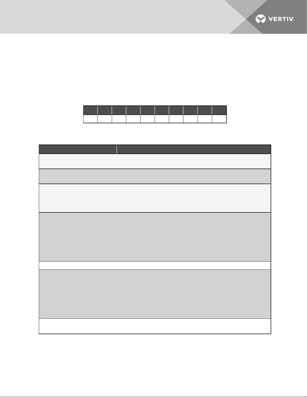
Table 2.1 Liebert Drycooler Model Number Example
1 2 3 4 5 6 7 8 9 10
D D N T 3 5 0 A 4 8
Table 2.2 Drycooler Model-number Digit Definitions
Digit Description
Digit 1 - Disconnect Switc h
D = Disconnect switch designat or on unit s wi thout pump cont rols, see Digit 3., otherwi se blank.
Digit2 = Uni t Fami ly
D = Dry cooler
Digit 3 - P ump Cont rol
N = No pump c ontrol
S = Single pump contr ol
D = Dual pump cont rol
Digits 4 - Fan C ontrol
C = No fan cont rol
L = Main fan c ontrol
T = Fa n cycl ing
O = Fan cy cli ng and pump cont rol
S = Specia l-or der fan/pump cont rol
F = Fan speed contr ol
Digits 5, 6, 7 - Model Size
Digit 8 - Power Supply
P = 208/ 230V / 1ph / 60Hz
W = 200 /2 20V / 1ph / 50 Hz
Y = 208/ 230V / 3ph / 60 Hz
A = 460V / 3ph / 60H z
B = 575V / 3ph / 60Hz
M = 380/415V / 3ph / 50 Hz
Digits, 9 and 10 - Cir cuit ing
Blank for standar d cir cuit ing. See Table 5.3 on page34 and Table 5.4 on pag e35 for sta ndard and optiona l ci rcui ti ng.
2 Nomenclature and Components
7
Page 12
2.2 Product Description and Features
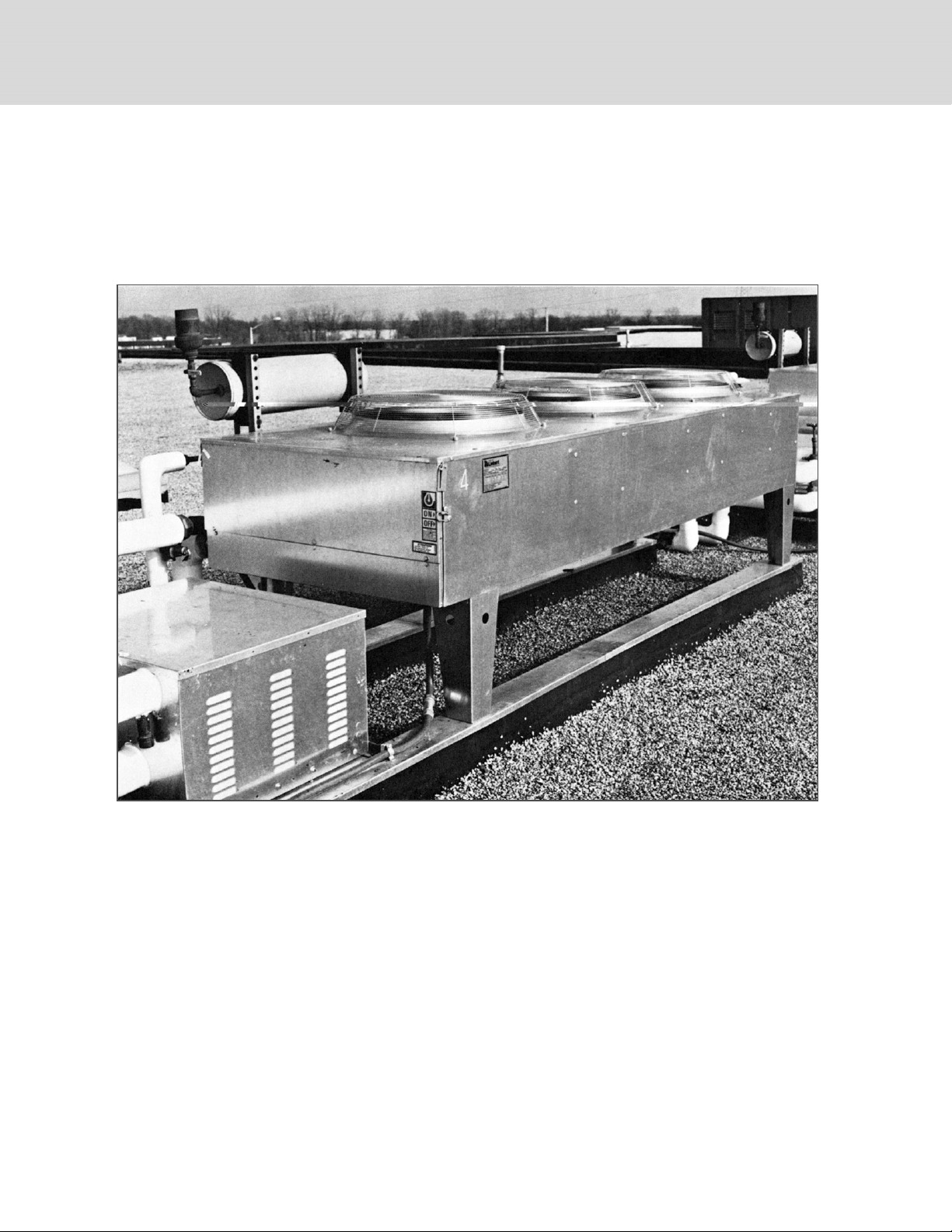
The Liebert® Air-cooled, Direct-drive Drycooler is a low-profile, direct-drive propeller fan-type air-cooled unit. Constructed
with an aluminum cabinet and a copper-tube aluminum fin coil, the unit is quiet and corrosion resistant. All electrical
connections and controls are enclosed in an integral NEMA 3R rated electrical panel section of the drycooler.
Figure 2.1 Liebert® Three Fan Drycooler
2.2.1 Control Options
Fan Speed—DSF, DDF
Available only on single-fan standard drycoolers with integral pump controls. Fan speed control provides an infinite number
of speed variations on specially designed, single-phase, permanent split capacitor motor, by monitoring leaving fluid
temperature.
Fan speed control provides air delivery in direct proportion to heat rejection requirements of the system. The control is
adjustable to maintain the temperature of the fluid leaving the drycooler. Either of two temperature ranges can be fieldselected: 30 to 60°F (-1 to 16°C) for GLYCOOL™applications or 70 to 100°F (21 to 38°C) for glycol applications.
8
Vertiv | Liebert ® Drycooler Installer/U ser Guide
Page 13

Fan Cycling Control—DDNT, DSO, DDO
Available on all sizes of standard sound and Quiet-Line drycoolers. A thermostatic control cycles the fan on a single-fan
drycooler in response to leaving fluid temperatures. Two or more thermostats are employed on drycoolers with two or more
fans to cycle fans or groups of fans in response to leaving fluid temperatures. The thermostat setpoints are listed on the
factory-supplied schematic. They typically range from 35 to 45°F (2 to 7°C) for GLYCOOL applications and 65 to 75°F (18 to
24°C) for glycol applications.
Main Fan Control—DDNL
Available on all sizes of standard-sound and Quiet-Line drycoolers without pump controls. All fans run when an external
contact closure completes internal 24VAC circuit.
No Controls - DDNC
Available on all sizes of standard-sound and Quiet-Line drycoolers without pump controls. All fans are activated at full
speed when power is applied to the drycooler.
Pump Controls
Available on all Fan Speed and Fan Cycling Control drycoolers. Controls for pump(s) up to 7.5hp are built into the same
integral electric panel as the drycooler fan controls. Pump fuses, overload heaters and flow switch (dual pump control
models) are included with the Liebert® pump packages or must be field-supplied for field-supplied pumps.
Dual pump option—Provides controls for primary and standby pump. The flow switch senses loss of flow and switches to the
standby pump for continuous system operation in the event of a pump failure. An internal switch allows manual selection of
the lead/lag pump.
2.2.2 Typical System Configurations
The standard glycol-cooled precision air conditioning system includes these major components:
• indoor air conditioning unit with heat exchangers (refrigerant/glycol)
• glycol regulating valve
• outdoor air-cooled drycooler
• glycol pump(s)
• expansion/compression tank
• pump controls
• interconnection piping
• unit interlock control wiring
The piping general-arrangement drawings, listed in Table 2.3 on the next page, show single unit to drycooler loop
arrangement, multiple indoor units and multiple outdoor drycoolers using a dual pump package and on a common piping
loop. The drawings are included in the Submittal Drawings Contents on page65.
Additional field-supplied components, such as valves, expansion tank, strainers and flow or pressure switches are also shown
in the piping general-arrangement drawings. These components are necessary and should be included when designing a
system with one indoor and one outdoor unit on a piping loop or a system using multiple indoor and outdoor units on a
common piping loop. Larger systems may also benefit from an air separator (not shown).
2 Nomenclature and Components
9
Page 14
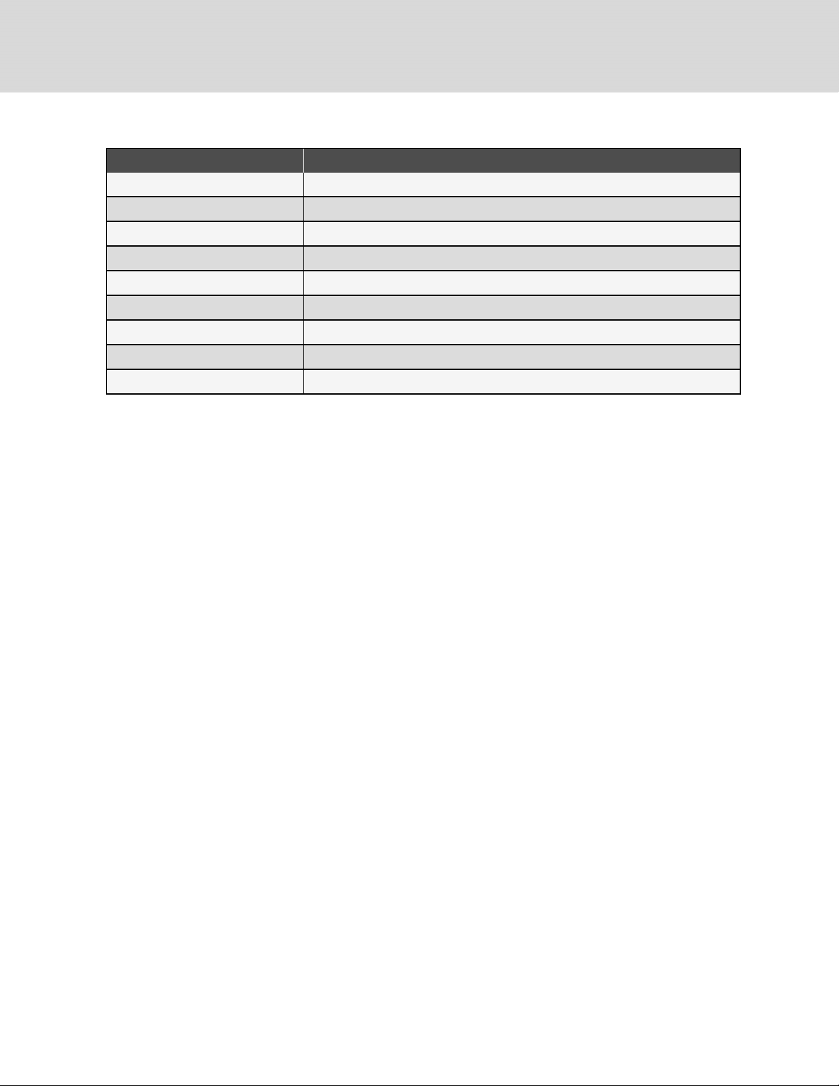
Table 2.3 Piping General-arrangment Drawings
Document Number Title
DPN000895 Piping diagram, Liebert® DS, glycol, semi-hermetic compressor models
DPN000896 Piping diagram, Liebert®DS, water/glycol, scroll compressor models
DPN001430 Piping diagram, Liebert® DS, water/glycol, digital-scroll com pressor models
DPN001432 Piping diagram, Liebert® DS, GLYCOOL, digital-scroll com pressor models
DPN000897 Piping diagram, Liebert®DS, GLYCOOL, semi-hermetic compressormodels
DPN000898 Piping diagram, Liebert®DS, GLYCOOL, scroll compressor m odels
DPN002931 Piping diagram, Liebert® PDX with water/glycol
DPN002932 Piping diagram, Liebert® PDX with GLYCOOL
DPN003822 Typical piping arrangement with multiple drycoolers and multiple indoor units
10
Vertiv | Liebert ® Drycooler Installer/U ser Guide
Page 15
3 PREINSTALLATION ANDSITEPREPARATIONGUIDELINES
The unit dimensions, pipe-connection locations, and piping schematics are described in the submittal documents included
in the Submittal Drawings Contents on page65.
• Install the drycooler in a location offering maximum security and access for maintenance.
• Avoid ground-level sites with public access and areas prone to heavy snow or ice accumulations.
• Whenever interior building locations must be used, utilize a Piggyback drycooler. Contact your Vertiv sales
representative for more information.
• To ensure adequate air supply, we recommend that drycoolers be installed in an area with clean air, away from
loose dirt and foreign matter that might clog the coil, and away from steam, hot-air, or fume exhaust.
• Drycoolers must not be installed in a pit because discharge air is likely to be recirculated through the unit.
• Drycoolers should be located no closer than 3 ft (1m) from a wall, obstruction, or adjacent unit and avoid
locations where objects restrict the air-inlet free area.
• For roof installation, mount the drycooler on suitable curbs or other supports in accordance with local codes.
• The drycooler must be installed on a level surface to ensure proper glycol flow, venting and drainage.
• Allow adequate space for pump packages, expansion/compression tanks, piping and additional field-supplied
devices.
• When mounting pump packages, mount on level surface or suitable curbs that will allow cooling ventilation air
to enter from underneath the pump package frame and exit through the louvers.
• The drycooler must be installed in a vertical air-flow orientation to maintain NEMA 3R rating of electrical box.
The unit is CSA c-us Certified for vertical air flow only and has not been tested for any other orientation.
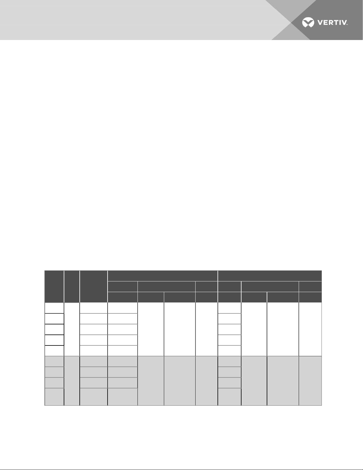
3.1 Shipping Dimensions and Weights
Table 3.1 Standard Drycooler Net Weights, Shipping Weights, Dimensions and Volume, Approximate
Domestic Packed Export Packed
No. of
Model
*D**033
*D**069 375 (17 0) 530 (240) 637 (289)
*D**092 395 (179) 550 (249) 657 (298)
*D**109 415 (188) 570 (259) 677 (307 )
*D**112 435 (197) 590 (268) 697 (316)
*D**139
*D**174 540 (245) 797 (362) 954 (433)
*D**197 580 (263) 837 (380) 994 (451)
*D**225 620 (281) 877 (398)
Dry Weight
Fans
lb (kg)
355 (161) 510 (231)
1
500 (227 ) 757 (343)
2
Weight Dimension (LxWxH) Volume Weight Dimension (LxWxH) Volume
lb. (kg) in. (cm) ft3(m3) lb. (kg.) in. (cm) ft3(m3)
617 (280)
62x36x63 (157x91x160) 81 (2.3)
914 (415)
102x36x63 (259x91x160) 134 (3.8)
1034
(469)
63x37x 64 (160x94x163) 86 (2.5)
103x37x64 (262x94x163) 141 (4.0)
3 Pr einst allation andS itePreparationGuideli nes
11
Page 16
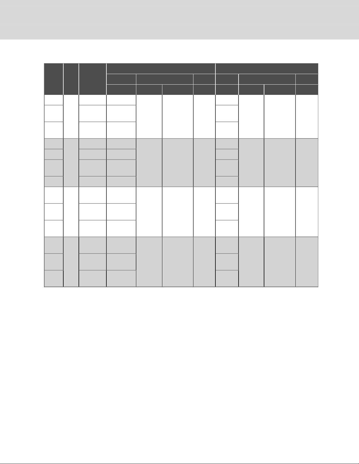
Table 3.1 Standard Drycooler Net Weights, Shipping Weights, Dimensions and Volume, Approximate (continued)
Domestic Packed Export Packed
No. of
Model
Fans
Dry Weight
lb (kg)
Weight Dimension (LxWxH) Volume Weight Dimension (LxWxH) Volume
lb. (kg) in. (cm) ft3(m3) lb. (kg.) in. (cm) ft3(m3)
*D**260
*D**310 795 (361) 1164 (528)
*D**350 855 (388) 1224 (555)
*D**352
735 (333) 1104 (501)
3
940 (426) 1401 (635)
142x36x63 (361x91x 160) 186 (5.3)
1282 (582)
1342
(609)
1402
(636)
1658 (752)
*D**419 1 020 (463) 1481 (672) 1738 (788)
*D**466 1050 (476) 151 1 (685)
4
182x36x63 (462x91x 160) 239 (6.7)
1768
(802)
*D**491 1100 (499) 1561 (708) 1818 (825)
*D**620
1780 (808) 2223 (1008)
6
*D**700 1 880 (854) 2323 (1054)
*D**790
*D**880 2330 (1058) 2895 (131 3)
2250 (1022) 2815 (1277 )
8
142x36x94 (361x91x239) 2 78 (7.9)
182x36x94 (462x91x2 39)
356
(10.0)
2948
(1337)
2998
(1360)
3048
(1383)
3769
(1710)
3849
(1746)
143x37 x64 (363x94x163) 1 96 (5.6)
183x37x64 (465x94x163) 251 (7.0)
143x37 x95 (363x94x241) 291 (8.2)*D**650 1830 (831) 2273 (1031)
183x37x95 (465x94x241) 372 (10.5)
*D**940 2430 (1103) 2995 (1359)
12
3949
(1791)
Vertiv | Liebert ® Drycooler Installer/U ser Guide
Page 17
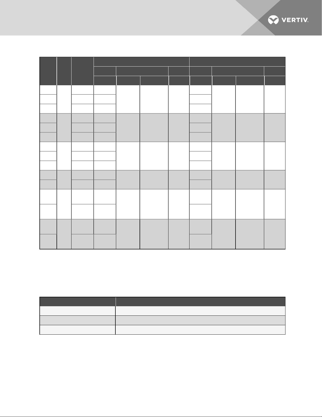
Table 3.2 Quiet-Line Drycooler Net weights, Shipping Weights, DimensionsandVolume,Approximate
Domestic Packed Export Packed
No. of
Model
Fans
Dry Weight
lb (kg)
Weight Dimension (LxWxH) Volume Weight Dimension (LxWxH) Volume
lb. (kg) in. (cm) ft3(m3) lb. (kg.) in. (cm) ft3(m3)
*D**040
*D**060 415 (188) 570 (259) 677 (307)
*D**080
*D**121 580 (263) 837 (380) 994(451)
*D**158
*D**178 855 (388) 1224 (555) 1402 (636)
*D**205
*D**248 1020 (463) 1481 (672) 1 738 (788)
*D**347
*D**356 1880 (854)
*D**453
*D**498
375 (17 0) 530 (240)
1
500 (227 ) 757 (343)
2
735 (333) 110 4 (501)
3
940 (426) 1 401 (635)
4
1780 (808)
6
2250
(1022)
8
2430
(1103)
2223
(1008)
2323
(1054)
2815 (1277)
2995
(1359)
637 (289)
62x36x63 (157x91x160) 81 (2.3)
914 (415)
102x36x63 (259x91x1 60) 134 (3.8)
1282 (582)
142x36x63 (361x91x160) 186 (5.3)
1658 (752)
182x36x63 (462x91x160) 239 (6.7)
2948
(1337)
142x36x94 (361x91x239) 278 (7. 9)
3048
(1383)
3769
(1710)
182x36x94 (462x91x239) 356 (10.0)
3949 (1791)
63x37x 64 (160x94x163) 86 (2.5)*D**057 395 (179) 550 (249) 657 (298)
103x37x64 (262x94x163) 141 (4.0)*D**111 540 (245) 797 (362) 954 (433)
143x37 x64 (363x94x163) 196 (5.6)*D**173 795 (361) 1 164 (528) 1342 (609)
183x37x64 (465x94x163) 251 (7. 0)
143x37 x95 (363x94x241) 291 (8.2)
183x37x95 (465x94x241) 372 (10.5)
3.2 Planning Dimensions and Anchor Plans
The unit dimensions are described in the submittal documents included in the Submittal Drawings Contents on page65.
The following table lists the relevant documents by number and title.
Table 3.3 Dimension Planning Drawings
Document Number Title
DPN000274 Cabinet and Anchor dimensions for 1to4f an drycoolers
DPN000280 Cabinet and Anchor dimensions for 1 to4 fan Quiet-Line drycoolers
DPN000721 Cabinet and Anchor dimensions for 6to8 fa n standard and Quiet-Line drycoolers
3 Pr einst allation andS itePreparationGuideli nes
13
Page 18
3.3 Pump Packages
The planning dimensions, electrical power-supply requirements, piping connections, and electrical connections are
described in the submittal documents included in the Submittal Drawings Contents on page65.
The following table lists the relevant documents by number and title.
Table 3.4 Drycooler Pump Drawings
Document Number Title
DPN000329 Pump Electrical Power Data and Piping-connection sizes.
DPN000278 Single-pump Piping connection locations and dimensional data
DPN000328 Dual-pump Piping connection locations and dimensional data
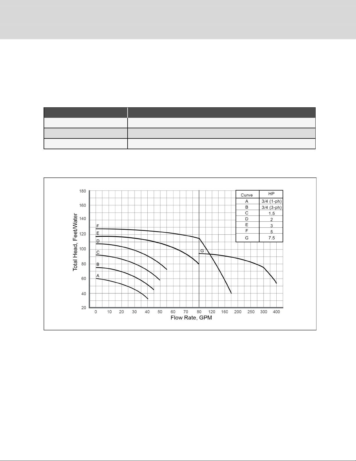
Figure 3.1 Pump curve, 60 Hz
NOTE: Higher-capacity pumps are available. Please contact your local sales rep for more information.
14
Vertiv | Liebert ® Drycooler Installer/U ser Guide
Page 19
3.3.1 Expansion Tank
The expansion tank, included in a standard pump package, has an internal volume of 8.8gal.(33l) and a maximum pressure
of 100psi(690kPa).
The tank is sized for a typical “open” system with a fluid volume of less than 75gal.(280l). When used in a “closed” system,
volumes of up to 140gal.(530l) can be accommodated. We recommend use of a field-supplied safety-relief valve for
systems “closed” to atmospheric venting. Other piping accessories for filling, venting, or adjusting the fluid in the system,
are recommended, but not included.
The planning dimensions and general arrangement are described in the submittal documents included in the Submittal
Drawings Contents on page65.
The following table lists the relevant documents by number and title.
Table 3.5 Drycooler Pump and Tank Drawings
Document Number Title
DPN004183 Expansion Tank General Arrangement and Dimensional Data
3.3.2 Compression Tank
The compression tank for glycol/GLYCOOL™ systems includes:
• Tank
• Airtrol fitting
• Sight glass with shut-off valves
• 50-psi relief valve
• Drain valve
Mounting brackets are not included. Maximum design pressure 125psig.
The planning dimensions and general arrangement are described in the submittal documents included in the Submittal
Drawings Contents on page65.
The following table lists the relevant documents by number and title.
Table 3.6 Drycooler Pump and Tank Drawings
Document Number Title
DPN003898 Compression Tank General Arrangement and Dimensional Data
3 Pr einst allation andS itePreparationGuideli nes
15
Page 20

This page intentionally left blank
16
Vertiv | Liebert ® Drycooler Installer/U ser Guide
Page 21
4 EQUIPMENT INSPECTION AND HANDLING
WARNING! Risk of improper moving, lifting, or handling of the unit. Can cause equipment damage, injury or
death. Read all of the following instructions and verify that all lifting and moving equipment is rated for the
weight of the unit before attempting to move, lift, remove packaging from or prepare the unit for installation.
SeeTable 3.1 on page11, and Table 3.2 on page13
CAUTION: Risk of contact with sharp edges, splinters, and exposed fasteners. Can cause injury. Only
properly trained and qualified personnel wearing appropriate, OSHA-approved PPE should attempt to move,
lift, remove packaging from or prepare the unit for installation.
NOTICE
Risk of improper lifting. Can cause equipment damage. Make sure that the spreader bars are wider than the
unit. If the spreader bars are too short, the slings may crush the unit.
NOTICE
Risk of damage from forklift. Can cause unit damage. Keep tines of the forklift level and at a height suitable to
fit below the skid and/or unit to prevent exterior and/or underside damage.
NOTICE
Risk of improper storage. Keep the unit upright, indoors and protected from dampness, freezing temperatures
and contact damage.
Upon arrival of the unit and before unpacking:
• Verify that the labeled equipment matches the bill of lading.
• Carefully inspect all items for visible or concealed damage.
• Report damage immediately to the carrier and file a damage claim with a copy sent to Vertiv or to your sales
representative.
Equipment Recommended for Handling the Unit:
• Forklift
• Lift beam
• Slings
• Spreader bars
• Crane
4.1 Packaging Material
All material used to package this unit is recyclable. Please save for future use or dispose of the material
appropriately.
4 Eq uipment Ins pection an d Handlin g
17
Page 22
4.2 Unit Storage
Store the drycooler in the original packaging in an area protected from excessive dirt, debris and contact damage until final
installation
4.3 Handling Unit on the Skid
Transport unit using a fork lift or a crane with sling and spreader bars.
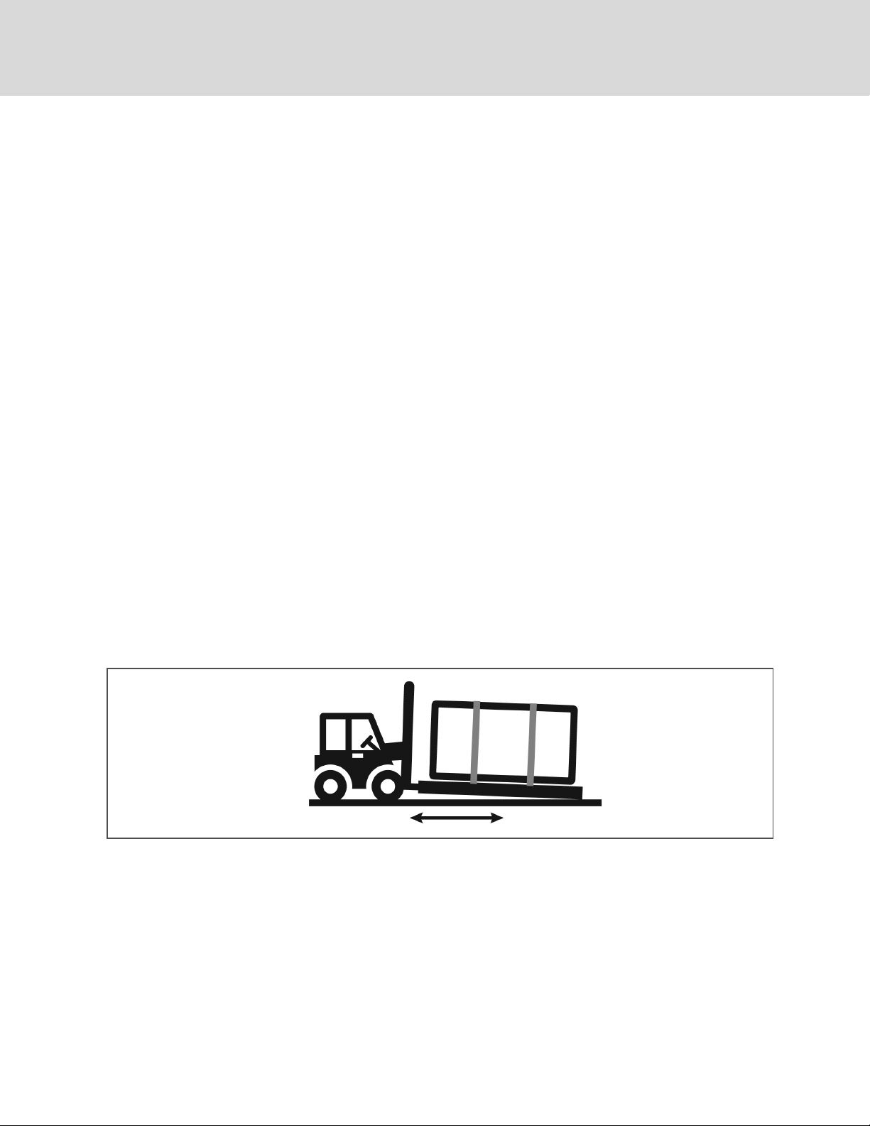
Using a forklift
NOTICE
Risk of improper forklift handling. Can cause unit damage.
Keep the forklift tines level and at a height that will fit under the skid.
• Make sure the forks (if adjustable) are spread to the widest allowable distance to still fit under the skid.
• Type of forklift used will depend on the terrain the unit is to be moved across during handling.
• Minimum forklift fork length:
• for 1 fan and two fan units—48in (1219mm)
• for 3 fan and 4 fan units—72in. (1829mm)
• for 6 fan units—72 in. (1829 mm)
• for 8 fan units—96 in. (2438 mm)
• When moving the packaged unit, do not lift it any higher than 6in. (152mm). If the unit must be lifted higher
than 6-in. (152mm), you must exercise great care, and no one may be closer than 20ft(6m) to the lift point.
• We recommend lifting one end off the ground no more than 6in.(152mm)and using the forklift to push or pull
the unit.
Figure 4.1 Forklift position with 1 to 8fan units
Using a Crane
• We recommend using slings rated for the unit weight.
• Spreader bars must be used for sling stability and to keep the slings from pressing against the unit. Make sure
spreader bars are wider than the unit.
• Place the slings near the ends of the unit, under the top deck boards of the skid.
18
Vertiv | Liebert ® Drycooler Installer/U ser Guide
Page 23
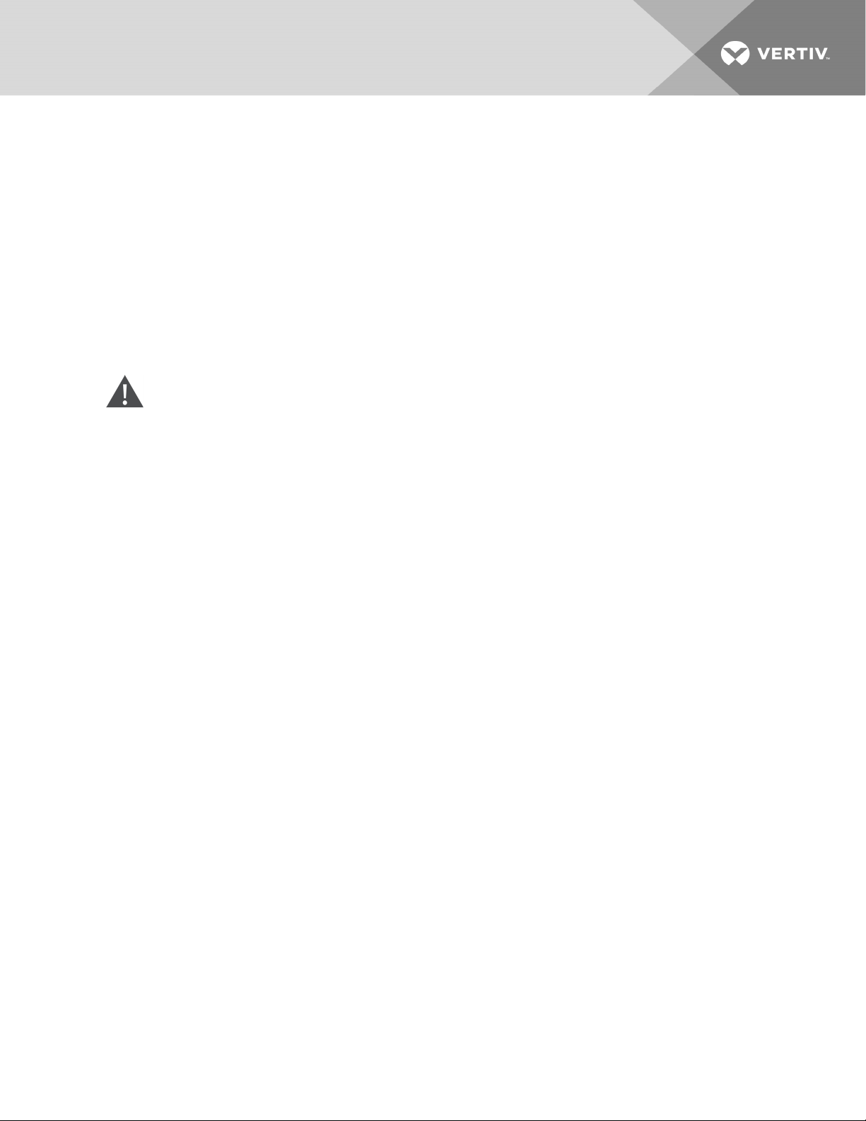
4.4 Unpacking the Unit—All Unit Sizes
Refer to Figure 4.2 on the next page, for the following steps:
1. For domestic packaging:
• Remove the fastener clamps from the top and sides of the unit.
• Remove all screws and washer from the wooden fencing.
• Remove the fence
–or–
For export packaging, remove the crate.
2. Carefully remove the steel straps securing the unit to the skid.
CAUTION: Risk of unsecured strap ends with sharp edges flying uncontrollably in any direction when cut.
Can cause serious injury. Secure both ends of each strap when cutting and wear OSHA approved protective
headgear, gloves and eye protection when working with the securing straps.
3. Set the legs aside, but keep accessible.
• Depending on the number of fans, more or less steel straps may be removed at this step.
4 Eq uipment Ins pection an d Handlin g
19
Page 24
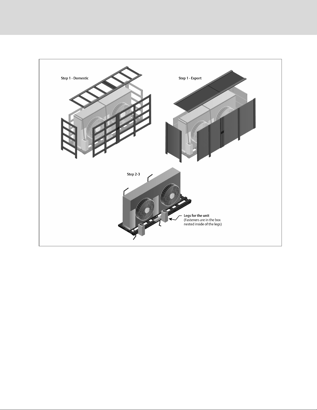
Figure 4.2 Removing Protective Material
20
Vertiv | Liebert ® Drycooler Installer/U ser Guide
Page 25
4.5 Preparing 1 to 4 Fan Drycooler forMovingandInstallation
The following procedure is one recommended method for removing a unit from the shipping skid. Other methods may be
used, provided that they are safe for personnel, the unit and equipment.
1. Attach legs to the unit at indicated locations, using the fasteners provided with the legs, Figure 4.3 below.
• Recommended tools for attachment is a 5/8” socket and ratchet.
• More legs may be available for installation than are shown. This will depend on the unit type and number
of fans. Refer to the appropriate planning-dimensions drawing in Submittal Drawings Contents on
page65, for the number of legs on your unit.
Figure 4.3 Attaching Legs to 1 to 4 Fan Drycoolers
4 Eq uipment Ins pection an d Handlin g
21
Page 26
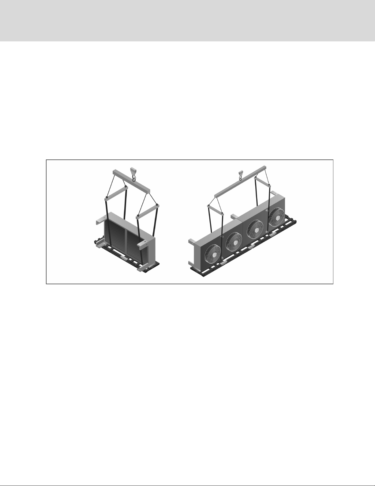
2. Place slings around the unit between the unit and the top deck boards of the skid as shown in Figure 4.4
below:
• 1 fan, 2 fan and 3 fan units: against the inside of the attached legs.
• 4 fan units: against the outside of the attached eye bolts.
3. Use spreader bars, a lift beam and a crane to lift the unit off the skid. Make sure spreader bars are wider than
the unit to prevent crushing force.
NOTICE
Risk of improper lifting. Can cause equipment damage. Make sure that the spreader bars are wider than the
unit. If the spreader bars are too short, the slings may crush the unit.
Figure 4.4 Securing Slings to 1 to 4 Fan Drycoolers for Lifting off Skid
22
Vertiv | Liebert ® Drycooler Installer/U ser Guide
Page 27
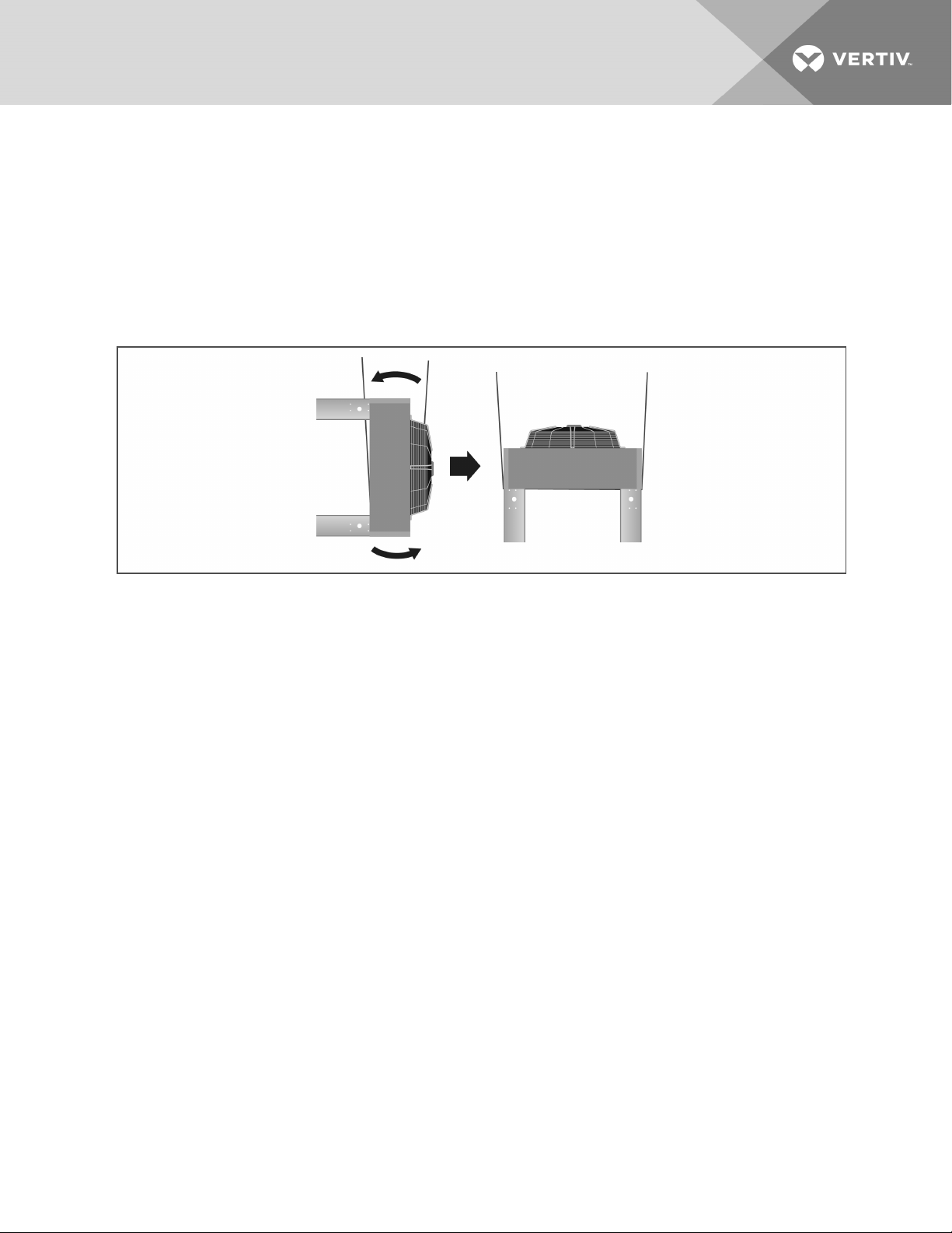
4. Lift the unit 24" (610mm) off the top deck of the skid.
5. Remove the skid from under the unit.
6. To rotate the unit, a mechanized method is recommended, but if one is not available, use a minimum of four
properly-protected individuals to rotate the elevated unit 90 degrees so the unit legs are pointing toward the
ground, Figure 4.5 below.
7. Set the upright unit on the ground so the legs support unit weight.
8. Remove the straps from around unit.
Figure 4.5 Rotate and Set Drycooler on Ground or Level Surface
4 Eq uipment Ins pection an d Handlin g
23
Page 28
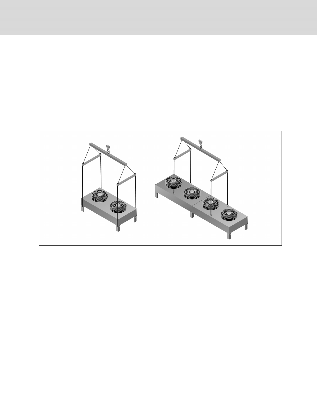
9. Refer to Figure 4.6 below, to attach rigging for lifting.
Spreader bars are still required. Make sure that the spreader bars are wider than the unit.
• 1 fan, 2 fan and 3 fan units: Route the straps through the large holes in the side of the legs.
• 4-fan units: Secure straps or chains to the eye bolts on top of the unit.
NOTICE
Risk of improper lifting. Can cause equipment damage. Make sure that the spreader bars are wider than the
unit. If the spreader bars are too short, the slings may crush the unit.
The unit is ready to be lifted and moved to its installation location.
Figure 4.6 Rigging to Lift 1 to 4 Fan Drycoolers
24
Vertiv | Liebert ® Drycooler Installer/U ser Guide
Page 29
4.6 Preparing 6 and 8 Fan Drycoolers for Moving and Installation
The following procedure is one recommended process for removing a unit from the shipping skid. Other methods may be
used, provided that the methods are safe for personnel, the drycooler and equipment.
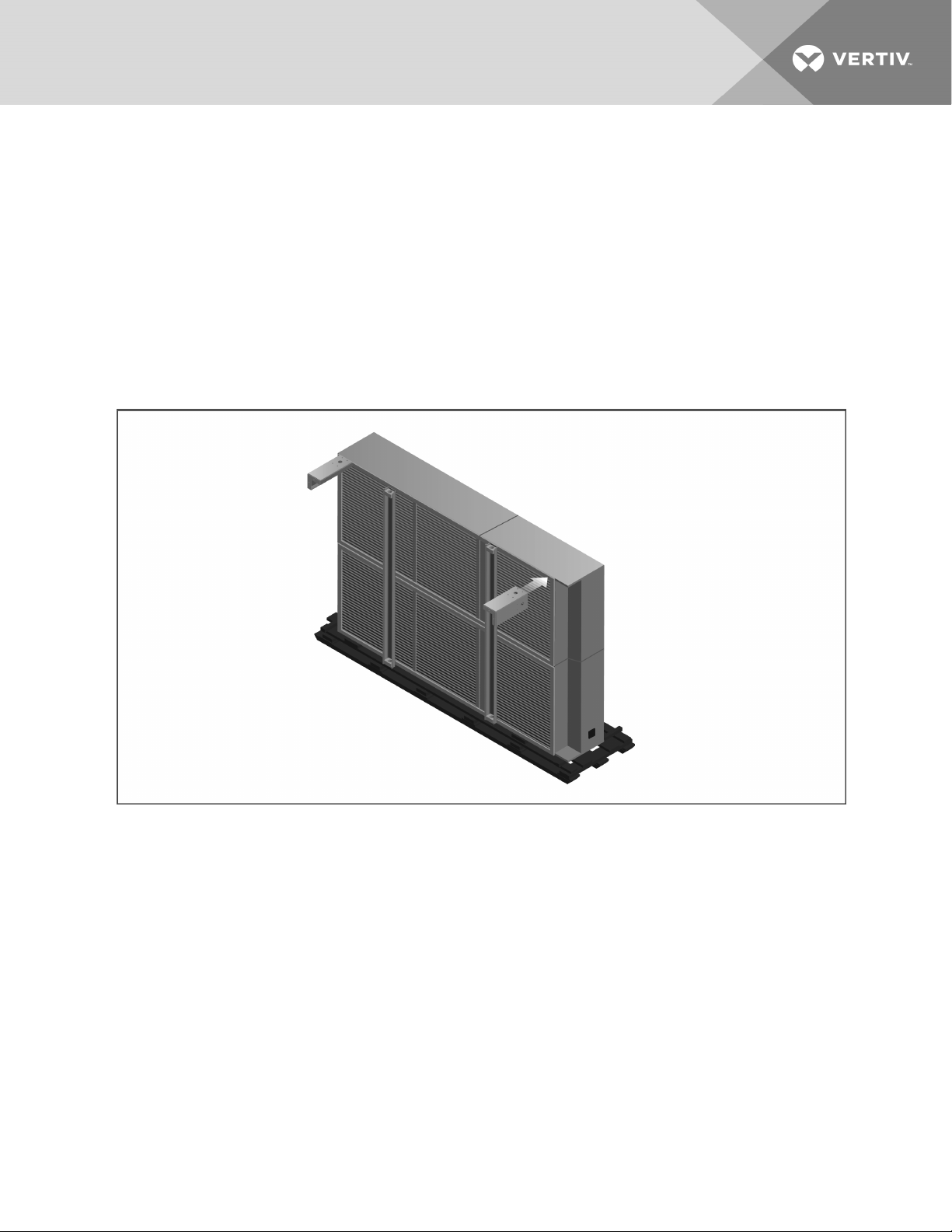
1. Refer to Figure 4.7 below, to attach the legs to the higher side of the unit:
• Use four (4) fasteners per leg. Fasteners are provided with the legs.
• Recommended tools for attachment is a 5/8” socket and ratchet.
• More legs may be required for installation than are shown. This will depend on the unit type and number
of fans. Refer to the appropriate planning-dimensions drawing in Submittal Drawings Contents on
page65, for the number of legs on your unit.
Figure 4.7 Attach Legs to Higher side of 6 or 8 Fan Drycooler
4 Eq uipment Ins pection an d Handlin g
25
Page 30
2. Attach slings or chains to the unit lift rails as shown in Figure 4.8 below
• Mechanically lower the unit in order to rest on the attached legs.
• Make sure not to damage the opposite side of the unit.
Figure 4.8 Use Sling to Lower Side with Legs Attached
26
Vertiv | Liebert ® Drycooler Installer/U ser Guide
Page 31

3. Move the slings or chains to the lift rail side that is resting on the skid, Figure 4.9 below.
• Mechanically lift the unit to a point where the side being lifted is just high enough to allow for safe
attachment of the remaining unit legs.
• Move the skid out the way and attach remaining legs.
Figure 4.9 Move Sling to Side Resting on Skid and Lift to Remove Skid and Install Legs
4 Eq uipment Ins pection an d Handlin g
27
Page 32

4. Set the upright unit on the ground so that the legs support the unit’s weight.
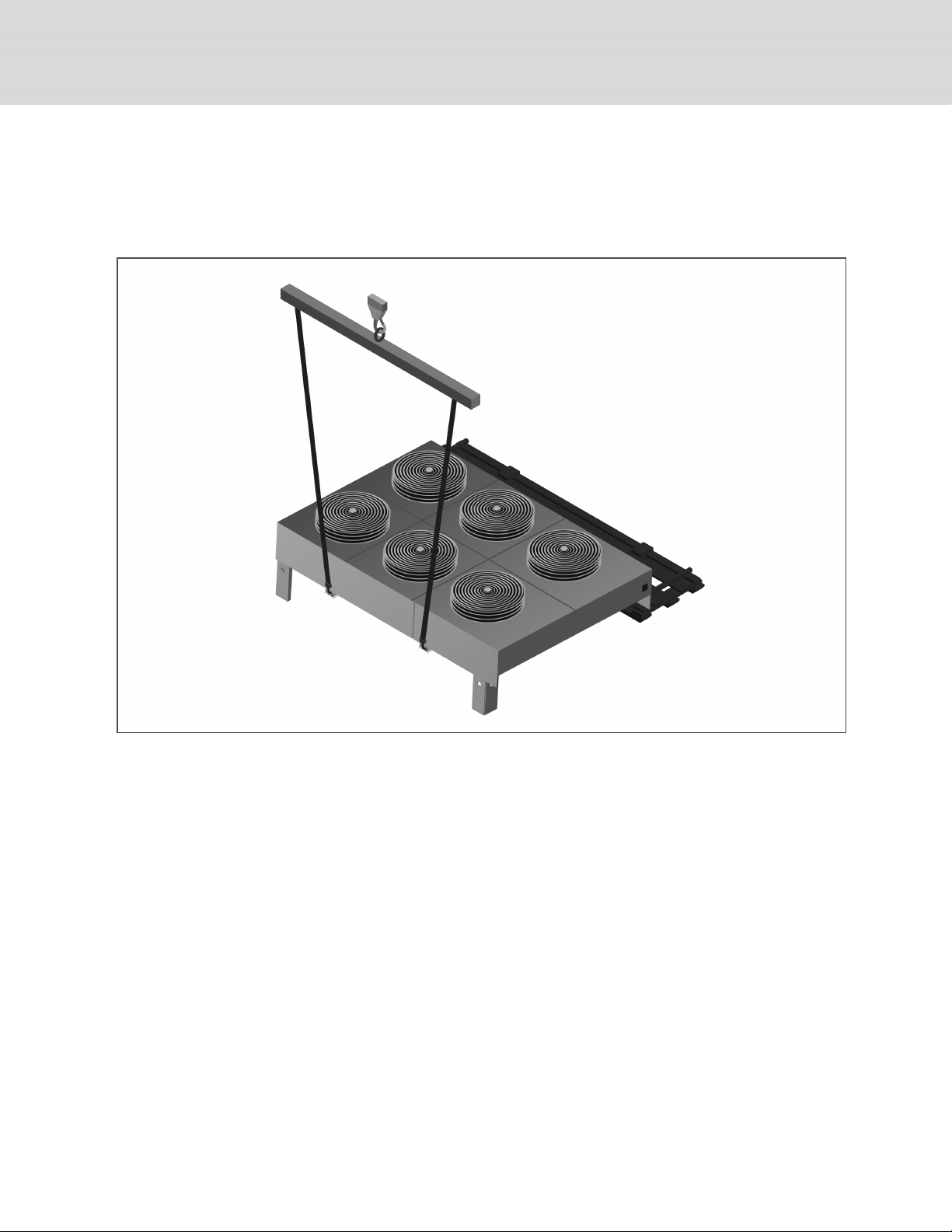
5. Reposition and add straps and spreader bars to prepare the unit for lifting to installation location, Figure 4.10
below.
• Use the support channels located under the unit to attach straps or chains.
• Spreader bars are still required. Make sure spreader bars are wider than the unit to keep the straps from
pressing on the sides of the unit.
NOTICE
Risk of improper lifting. Can cause equipment damage. Make sure that the spreader bars are wider than the
unit. If the spreader bars are too short, the slings may crush the unit.
The unit is ready to be lifted and moved to its installation location.
Figure 4.10 Rigging 6 and 8 Fan Drycooler for Lifting
28
Vertiv | Liebert ® Drycooler Installer/U ser Guide
Page 33

4.7 Mounting the Drycooler
The drycooler must be installed so that it is level within 1/2in.(13mm) to ensure proper glycol flow, venting, and drainage.
For roof installation, mount the drycooler on suitable curbs or other supports. Follow all local and national codes. Secure the
legs to the mounting surface using a field-supplied 1/2-in.(13-mm) diameter bolt in each of the two 9/16-in. (14-mm) holes in
each leg. For anchor dimensions, refer to the appropriate drawing for your unit model included in the Submittal Drawings
Contents on page65.
4 Eq uipment Ins pection an d Handlin g
29
Page 34

This page intentionally left blank
30
Vertiv | Liebert ® Drycooler Installer/U ser Guide
Page 35

5 PIPING
NOTICE
Risk of piping-system corrosion and freezing fluids. Can cause leaks resulting in equipment and expensive
building damage. Cooling coils and piping systems are at high risk of freezing and premature corrosion. Fluids
in these systems must contain an inhibitor to prevent premature corrosion.
The system coolant fluid must be analyzed by a competent fluid-treatment specialist before start up to
establish the inhibitor level and evaluated at regularly scheduled intervals throughout the life of the system to
determine the pattern of inhibitor depletion. The fluid complexity and variations of required treatment
programs make it extremely important to obtain the advice of a competent and experienced fluid-treatment
specialist and follow a regularly scheduled coolant-fluid system-maintenance program.
Fluid chemistry varies greatly as do the required additives, called inhibitors, that reduce the corrosive effect of
the fluids on the piping systems and components.
The chemistry of the coolant fluid used must be considered, because some sources may contain corrosive
elements that reduce the effectiveness of the inhibited formulation. Sediment deposits prevent the formation of
a protective oxide layer on the inside of the coolant system components and piping. The coolant fluid must be
treated and circulating through the system continuously to prevent the buildup of deposits and/or growth of
bacteria. Proper inhibitor maintenance must be performed to prevent corrosion of the system.
Consult fluid manufacturer for testing and maintenance of inhibitors.
Commercial-grade coolant fluid is generally less corrosive to the common metals of construction than water
itself. It will, however, assume the corrosivity of the coolant fluid from which it is prepared and may become
increasingly corrosive with use if not properly inhibited.
NOTICE
NOTICE
Vertiv recommends installing a monitored fluid-detection system that is wired to activate the automaticclosure of field-installed coolant-fluid supply and return shut-off valves to reduce the amount of coolant-fluid
leakage and consequential equipment and building damage. The shut-off valves must be sized to close-off
against the maximum coolant-fluid system pressure in case of a catastrophic fluid leak.
Risk of a catastrophic water circuit rupture. Can cause expensive building and equipment damage.
Install shutoff valves in the supply and return water lines that automatically close if water is detected by the
leak detection system. The shutoff valves should be spring return and must be rated for a close-off pressure
that is the same as or higher than the supply water pressure. monitored leak detection system should be
installed in the base of the unit or under the unit to actuate the shutoff valves immediately on a leak detection
signal.
Risk of no-flow condition. Can cause equipment damage.
Do not leave the water/coolant fluid-supply circuit in a no-flow condition. Idle fluid allows the collection of
sediment that prevents the formation of a protective oxide layer on the inside of tubes. Keep unit switched On
and water/coolant fluid-supply circuit system operating continuously.
5 Pi pin g
31
Page 36

Piping between the drycooler, any external pump and the cooling unit is required to complete the system.
Properly-sized pipes will help reduce pumping power and operating costs. Pipe material choices are typically copper,
plastic or steel/black iron. Consult glycol and pipe manufacturing literature for compatibility and sizing assistance.
Galvanized piping should not be used. Any copper piping installed should be “L” or “K” refrigerant-grade copper.
Drycooler supply and return connections vary in size and number. See Table 5.3 on page34, and Table 5.4 on page35.
Consider the following guidelines when planning and performing the piping installation:
• Follow local piping codes, safety codes.
• Qualified personnel must install and inspect system piping.
• Do not hang or suspend piping from the drycooler-tube sheets protruding below the finned sections of the coil.
• On multiple-pump packages install a check valve at the discharge of each pump to prevent back-flow through
the standby pump(s).
• To extend the service life of the drycooler and pumps, install 16-20 mesh-screen filters/strainers in the supply
line to the pumps. The filter/strainer(s) should be easily replaced or cleaned.
• Consider Installing hose bibs at the lowest point of the system to facilitate filling.
• Keep piping runs as straight as possible, avoid unnecessary bends, and minimize additional fittings.
• Isolate piping from the building with vibration-isolating supports. Use soft, flexible material to seal between
pipes and wall openings to prevent pipe damage.
• Use welded or high-temperature soldered joints where possible. Threaded pipe joints, if needed, can be made
with tightly drawn Teflon™ tape.
• Clean and prepare all pipe connections before joining. Be careful not to allow solder/joining debris to get inside
the lines during the connection process.
32
Vertiv | Liebert ® Drycooler Installer/U ser Guide
Page 37

The piping general arrangement and schematics are described in the submittal documents included in the Submittal
Drawings on page65.
The following tables list the relevant documents by number and title.
Table 5.1 Piping General-arrangment Drawings
Document Number Title
DPN000895 Piping diagram, Liebert® DS, glycol, semi-hermetic compressor models
DPN000896 Piping diagram, Liebert®DS, water/glycol, scroll compressor models
DPN001430 Piping diagram, Liebert® DS, water/glycol, digital-scroll com pressor models
DPN001432 Piping diagram, Liebert® DS, GLYCOOL, digital-scroll com pressor models
DPN000897 Piping diagram, Liebert®DS, GLYCOOL, semi-hermetic compressormodels
DPN000898 Piping diagram, Liebert®DS, GLYCOOL, scroll compressor m odels
DPN002931 Piping diagram, Liebert® PDX with water/glycol
DPN002932 Piping diagram, Liebert® PDX with GLYCOOL
DPN003822 Typical piping arrangement with multiple drycoolers and multiple indoor units
Table 5.2 Piping Connection Drawings
Document Number Title
DPN000275 Connection locations for standard 1 fan, 2 fan, 3 fan, and 4 fan units
DPN000281 Connection locations for Quiet-Line 1 fan, 2 fan, 3 fa n, and 4 fan units
DPN002429 Connection locations f or standard 6 fan and 8 fa n units
DPN002430 Connection locations for Quiet-Line 6 fan and 8 fan units
5 Pi pin g
33
Page 38

Table 5.3 Standard Drycooler Piping Connection Sizes and Internal Volume
Model #
No. of Internal Coil Circuits No. of Fans
Internal Volume,
gal. (L)
No. of Inlets/Outlets
Inlet & Outlet Connection Size
ODS Copper, in. IDS Copper, in.
033 4*
069 4, 8* 2.4 (9.2) 1/1 1-3/8 —
092 6, 12*, 16 3.7 (13.9) 1/1 1-5/8 —
109
8
16* 1/1 2-1/8 —
8
112
16*, 26 1/1 2-1/8 —
139 8, 16*
174 8, 16*, 24 6.9 (26.2) 1/1 2-1/8 —
8 9.0 (34.0) 1/1 1-3/8 —
197
16*, 32 9.0 (34.0) 1/1 2-1/8 —
225 16, 26* 11.1 (42.1) 1/1 2-1/8 —
260 16, 24*
310 16, 32* 13.1 (49.6) 1/1 2-1/8 —
16, 32*
350
48 1/1 2-5/8 —
352 16, 24*
1
2
3
1.2 (4.6) 1/1 1-3/8 —
1/1 1-3/8 —
4.9 (18.6)
1/1 1-3/8 —
5.8 (22.0)
4.8 (18.2) 1/1 2-1/8 —
10. 0 (37. 9) 1/1 2-1/8 —
1/1 2-1/8 —
19.4 (73.3)
13.1 (49.6) 1/1 2-1/8 —
419 16, 32* 17.4 (65.9) 1/1 2-1/8 —
466 26
466 40* 1/1 2-5/8 —
16, 32
491
48* 1/1 2-5/8 —
620 32, 64*
40, 52*
650
80 4/4 — 2-1/8
32, 64*
700
96 4/4 — 2-1/8
790 32, 64*
52
880
80* 4/4 — 2-1/8
32, 64
940
96* 4/4 — 2-1/8
* = Standard Circuiting
4
6
8
22.0 (83.3)
26.3 (99.6)
27. 0 (102 .2) 2/2 — 2-1/8
33.0 (124.9)
40.0 (151 .4)
35.0 (132.5) 2/2 — 2-1/8
44.0 (166.5)
52.0 (196.8)
1/1 2-1/8 —
1/1 2-1/8 —
2/2 — 2-1/8
2/2 — 2-1/8
2/2 — 2-1/8
2/2 — 2-1/8
34
Vertiv | Liebert ® Drycooler Installer/U ser Guide
Page 39

Table 5.4 Liebert Quiet-Line™ Drycooler Piping Connection Sizes and Internal Volume
Model # No. of Internal Coil Circuits No. of Fans
Internal Volume,
gal. (L)
No. of Inlets/Outlets
Inlet & Outlet Connection Size
ODS Copper, in. IDSCopper, in.
040 4, 8*
12*
057
16 1/1 2-1/8 —
8
060
1
2.4 (9.2) 1/1 1-3/8 —
1/1 1 -5/8 —
3.7 (13.9)
1/1 1 -3/8 —
4.9 (18.6)
16* 1/1 2-1/8 —
080 8, 16*
111 16*, 24 6.9 (26.2) 1 /1 2-1/8 —
2
4.8 (18.2) 1/1 2-1/8 —
121 1 6*, 32 9.0 (34.0) 1/1 2-1/8 —
158 1 6, 24*
10. 0 (37. 9) 1 /1 2-1/8 —
173 16, 32* 13.1 (49.6) 1/1 2-1/8 —
3
178
16, 32*
19.4 (73.3)
1/1 2-1/8 —
48 1/1 2-5/8 —
205 16, 24*
13.1 (49.6) 1/1 2-1/8 —
4
248 16, 32* 17.4 (65.9) 1/1 2-1/8 —
347 32, 64*
32, 64*
356
6
27. 0 (102 .2) 2/2 — 2-1/8
2/2 — 2-1/8
39.3 (148.8)
96 4/4 — 2-1/8
5 Pi pin g
453 32, 64*
498
* = Standard circuiting
35.0 (132.5) 2/2 — 2-1/8
32, 64
8
2/2 — 2-1/8
52.0 (196.8)
96* 4/4 — 2-1/8
35
Page 40

5.1 Guidelines for Expansion Tanks, Fluid-reliefValves,AirManagementandOtherDevices
An expansion tank must be provided for expansion and contraction of the fluid due to temperature change in this closed
system. Vents are required at system high points to vent trapped air when filling the system. A fluid pressure relief valve is
also a necessary piping component.
All systems must have an air management system to ensure proper component operation and system performance. There
are several methods that can be used to manage the air within a closed loop hydronic system. Depending on the method
chosen, the system may include one or more of the following ancillary components: tank-steel (expansion, compression,
diaphragm or bladder), air separator and air vent.
Consult your local engineer to determine which method will be used and where these components must be installed.
Depending on the complexity of the system, various other devices may be specified—refer to site-specific drawings. Some
of the devices that may be required are: pressure gauges, flow switches, automatic air separator, tempering valves, standby
pumps and sensors for electrical controls.
5.2 Preparing to Fill the System
NOTICE
Risk of improper handling of glycol products. Can cause environmental damage.
Before using any glycol products, review the latest manufacturer's Material Safety Data Sheets and ensure that
you can use the product safely. The installer must read, understand and comply with the information on the
product packaging and in the current Material Safety Data Sheets. Make this information available to anyone
responsible for operation, maintenance and repair of the drycooler and related equipment.
Because government regulations and use conditions are subject to change, it is the user's responsibility to
determine that this information is appropriate and suitable under current, applicable laws and regulations.
NOTICE
Risk of using the wrong type of glycol. Can cause piping damage, coolant fluid leaks, and catastrophic and
expensive building and equipment damage.
Do not use automotive antifreeze as it contains chemicals that can damage the piping system.
Typical inhibited formula ethylene glycol and propylene glycol are supplied with corrosion inhibitors and do
not contain a silicone anti-leak formula. Commercial ethylene glycol and propylene glycol, when pure, are
generally less corrosive to the common metals of construction than water itself. Aqueous solutions of these
glycols, however, assume the corrosivity of the water from which they are prepared and may become
increasingly corrosive with use when not properly inhibited.
Remove any dirt, oil, or metal filings that may contaminate the cooling system piping to prevent contamination of the fresh
glycol solution and fouling of the drycooler piping. Flush the system thoroughly using a mild cleaning solution or highquality water and then completely drain before charging with glycol.
Cleaning a new system is just as important as cleaning an old one. New systems can be coated with oil or a protective film.
Dirt and scale are also common. Any residual contaminants could adversely affect the heat-transfer stability and
performance of your system. In most cases, special cleaners are needed to remove scale, rust, and hydrocarbon foulants
from pipes, manifolds, and passages. For more information on cleaners and degreasers, contact your Vertiv representative.
Follow the manufacturer’s instructions when using these products.
36
Vertiv | Liebert ® Drycooler Installer/U ser Guide
Page 41

Calculate the internal volume of the system as closely as possible. The drycooler volumes are shown in 5.2 on the previous
page, and 5.2 on the previous page. Use Table 5.5 below, for field-installed piping volumes. Indoor unit volumes are found
in their respective user manuals.
Table 5.5 Glycol volume in standard type "L" copper piping
Diameter, in. Volume
Outside Inside gal/ft l/m
1-3/8 1.265 0.065 0. 81
1-5/8 1.505 0.092 1.1 5
2-1/8 1 .985 0.161 2.00
2-5/8 2.465 0. 248 3.08
3-1/8 2.945 0.354 4.40
3-5/8 3.425 0. 479 5.95
4-1/8 3.905 0.622 7. 73
When considering the use of any glycol products in a particular application, review the latest Material Safety Data Sheets
and ensure that the intended use can be accomplished safely. For Material Safety Data Sheets and other product safety
information, contact the supplier nearest you. Before handling any other products mentioned in the text, you should obtain
available product safety information and take necessary steps to ensure safety of use.
Table 5.6 Glycol Concentrations for Freeze Protection by Ambient Temperature
Minimum Outdoor Ambient Tem perature, °F(°C)
Coolant 20 (–7) 10 (–12) 0 (–18) –10 (–23) –20 (–29) –30 (–34) –40 (–40) –50 (–46)
Propylene Glycol, % by volume 18* 29* 36 42 46 50 54 57
Ethylene Glycol, % by volume 17* 26* 35 41 46 50 55 59
Based on Dowfrost™ (PG) and Dowtherm™ (EG) product lit erature.
*Inhibitor levels should be adjusted to properly protect the syst em if solution concentrates are les s than 30% .
There are two basic types of additives:
• Corrosion inhibitors
• Environmental stabilizers
The corrosion inhibitors function by forming a surface barrier that protects the metals from attack. Environmental stabilizers,
while not corrosion inhibitors in the strictest sense, decrease corrosion by stabilizing or favorably altering the overall
environment. An alkaline buffer, such as borax, is a simple example of an environmental stabilizer, because its prime
purpose is to maintain an alkaline condition (pH above 7).
The percentage of glycol to water must be determined by using the lowest design outdoor temperature in which the system
is operating. Table 5.6 above, indicates the solution volume of inhibited glycol required to provide freeze protection at
various ambient temperatures.
5 Pi pin g
37
Page 42

5.3 Filling the Drycooler System
We recommend installing hose bibs at the lowest point of the system.
When filling a glycol system, keep air to a minimum. Air in glycol turns to foam and is difficult and time consuming to
remove. (Consider anti-foam additives.)
To fill the system:
1. Open all operating systems to the loop.
2. With the top vent(s) open, fill the system from the bottom of the loop.
The glycol will push the air out of the top of the system, minimizing trapped air.
3. Fill to approximately 80% of calculated capacity, then continue to fill slowly from this point, checking fluid
levels until full.
NOTE: For glycol solution preparation and periodic testing, follow manufacturer's recommendations. Do not mix
products of different manufacturers.
38
Vertiv | Liebert ® Drycooler Installer/U ser Guide
Page 43

6 ELECTRICAL CONNECTIONS
Line-voltage electrical service is required for all models. Electrical service must conform to national and local electrical
codes. Refer to equipment nameplate regarding wire size and circuit protection requirements. Refer to electrical schematic
when making connections. Refer the appropriate submittal drawing, listed in Table 6.1 on the next page, for electrical
service entrances into unit.
A manual electrical disconnect switch should be installed in accordance with local codes and distribution system. Consult
local codes for external disconnect requirements.
All internal wiring is completed at the factory.
WARNING! Arc flash and electric shock hazard. Open all local and remote electric power-supply disconnect
switches, verify with a voltmeter that power is Off and wear appropriate, OSHA-approved personal protective
equipment (PPE) per NFPA 70E before working within the electric control enclosure. Failure to comply can
cause serious injury or death. Customer must provide earth ground to unit, per NEC, CEC and local codes, as
applicable. Before proceeding with installation, read all instructions, verify that all the parts are included and
check the nameplate to be sure the voltage matches available utility power. The Liebert® controller does not
isolate power from the unit, even in the “Unit Off” mode. Some internal components require and receive
power even during the “Unit Off” mode of the controller. The factory-supplied disconnect switch is inside the
unit. The line side of this switch contains live high-voltage. The only way to ensure that there is NO voltage
inside the unit is to install and open a remote disconnect switch. Refer to unit electrical schematic. Follow all
local codes.
WARNING! Risk of improper wiring, piping, moving, lifting and handling. Can cause equipment damage,
serious injury or death. Installation and service of this equipment should be done only by qualified personnel
who have been specially-trained in the installation of air-conditioning equipment and who are wearing
appropriate, OSHA-approved PPE.
WARNING! Risk of improper wire sizing/rating and loose electrical connections. Can cause overheated wire
and electrical connection terminals resulting in smoke, fire, equipment and building damage, injury or death.
Use correctly sized copper wire only and verify that all electrical connections are tight before turning power
On. Check all electrical connections periodically and tighten as necessary.
NOTICE
Risk of improper power-supply connection. Can cause equipment damage and loss of warranty coverage.
Prior to connecting any equipment to a main or alternate power source (for example: back-up generator
systems) for start-up, commissioning, testing, or normal operation, ensure that these sources are correctly
adjusted to the nameplate voltage and frequency of all equipment to be connected. In general, power-source
voltages should be stabilized and regulated to within ±10% of the load nameplate nominal voltage. Also, ensure
that no three-phase sources are single-phased at any time.
NOTE: Use copper wiring only. Make sure that all connections are tightened to the proper torque mentioned on the
component.
6 Electrical Connections
39
Page 44

NOTE: Installation and service of this equipment should be done only by properly-trained and qualified personnel who
are specially-trained in the installation of air-conditioning equipment.
The electrical connections are described in the submittal documents included in the Submittal Drawings Contents on
page65.
The following table lists the relevant documents by number and title.
Table 6.1 Electrical Field Connection Drawings
Document Number Title
DPN000277 Electrical field connections, 1 fan DSF/DDF drycooler with pump control
DPN000276 Electrical field connections, 1, 2, 3 and 4 fan DSO/DDO drycooler with pump control
DPN000703 Electrical field connections, 6 a nd 8 fan DSO/DDO drycooler with pump control
DPN000702 Electrical field connections, 6 and 8 fan DDNC drycooler without pump control
DPN000704 Electrical field connections, 6 and 8 fan DDNL/DDNT drycooler without pump control
DPN000282 Electrical field connections, Fluid-temperature control drycooler, Q uiet-Line
DPN000722 Electrical field connections, 6- and 8-fan Quiet-Line drycooler with no control
DPN000723 Electrical field connections, 6- and 8-fan Quiet-Line drycooler with DSO/DDO pump control
DPN000724 Electrical field connections, 6- and 8-fan Quiet-Line drycooler with DDNL and DDNT pump control
6.1 Line Voltage Wiring
WARNING! Risk of electrical fire and short circuit. Can cause property damage, injury or death. Select and
install the line side electrical supply wire and overcurrent protection device(s) according to the specifications
on the unit nameplate(s), per the instructions in this manual and according to the applicable national, state
and local code requirements. Use copper conductors only. Verify that all electrical connections are tight.
Unit-specific wiring diagrams are provided on each unit.
NOTICE
Risk of improper power-supply connection. Can cause equipment damage and loss of warranty coverage.Prior to
connecting any equipment to a main or alternate power source (for example: back-up generator systems) for start-up,
commissioning, testing, or normal operation, ensure that these sources are correctly adjusted to the nameplate
voltage and frequency of all equipment to be connected. In general, power-source voltages should be stabilized and
regulated to within ±10% of the load nameplate nominal voltage. Also, ensure that no three-phase sources are singlephased at any time.
Drycooler-rated voltage should be verified with available power supply before installation. Refer to the unit’s electrical
schematic and serial tag for specific electrical requirements.
Line voltage electrical service is required for all drycoolers at the location of the drycooler. If the drycooler contains pump
controls, the pump package voltage must match the drycooler voltage. See the unit's serial tag for specific electrical
requirements of the drycooler and any pump package. A unit disconnect is standard on all drycoolers. Site disconnect (s)
may also be required per local code to isolate the drycooler/pumps for maintenance. Route the supply power to the site
disconnect switch and then to the drycooler. Route the conduit through the hole provided in the cabinet. Connect earth
ground to lug provided near the terminal board. Refer to the appropriate drawing in the Submittal Drawings Contents on
page65.
40
Vertiv | Liebert ® Drycooler Installer/U ser Guide
Page 45

NOTE: A separate neutral wire does not need to be run to the Liebert® Drycooler.
Table 6.2 60Hz Electrical Values—Drycoolers without Pump Controls
No. of Fans Model N o. Voltage Phase FLA WSA OPD
Standard Models
1 33, 69, 092, 109, 112
2 139, 174, 1 97, 225
3 260, 310, 350
4 352, 419, 466, 491
6 620, 650, 700
208/230
1 4.8 6 1 5
3 3.5 4.4 1 5
460 3 1. 7 2.1 15
575 3 1 .4 1.8 15
208/230 3 7 .0 7.9 15
460 3 3. 4 3. 8 1 5
575 3 2.8 3. 2 15
208/230 3 10.5 11.4 1 5
460 3 5.1 5.5 15
575 3 4.2 4.6 15
208/230 3 14.0 14.9 20
460 3 6.8 7. 2 15
575 3 5.6 6.0 15
208/230 3 21.0 21.9 25
460 3 10.2 10.6 15
575 3 8.4 8.8 15
208/230 3 28.0 28.9 35
6 Electrical Connections
8 790, 880, 940
Liebert® Quiet-Line Models
1 40, 57, 60
2 80, 1 11 , 1 21
3 158, 1 73, 178
4 205, 248
460 3 1 3.6 14.0 20
575 3 1 1. 2 11. 6 15
208/230 3 1 .8 2. 3 15
460 3 0.9 1 .1 1 5
575 3 0.7 0. 9 15
208/230 3 3.6 4.1 15
460 3 1. 8 2.0 1 5
575 3 1 .4 1.6 1 5
208/230 3 5.4 5.9 1 5
460 3 2.7 2.9 15
575 3 2.1 2.3 15
208/230 3 7.2 7.7 1 5
460 3 3. 6 3. 8 1 5
575 3 2.8 3.0 15
41
Page 46

Table 6.2 60Hz Electrical Values—Drycoolers without Pump Controls (continued)
No. of Fans Model N o. Voltage Phase FLA WSA OPD
208/230 3 10.8 11 .3 1 5
6 347, 356
8 453, 498
Values are calculated per UL 1995. OPD values may be adjusted higher than calculations to compensate for maximum
anticipated application temperatures.
460 3 5. 4 5. 6 15
575 3 4.2 4.4 15
208/230 3 14.4 14.9 20
460 3 7.2 7. 4 15
575 3 5.6 5.8 15
Table 6.3 50Hz Electrical Values—Drycoolerswithout
Pump Controls
No. of Fans Model # Voltage Phase FLA
Standard Models
1
2
3
33, 69, 92,
109, 112
139, 174, 197,
225
260, 310,
350
200/230 1 4.0
380/415 3 1 .7
380/415 3 3.4
380/415 3 5.1
4
6
8
Quiet-Line Models
1 40, 57, 60 380/415 3 0.9
2 80, 1 11, 121 380/415 3 1.8
3 158, 173, 17 8 380/415 3 2. 7
4 205, 248 380/415 3 3.6
6 347, 356 380/415 3 5. 4
8 453, 498 380/415 3 7 .2
352, 419,
466, 491
620, 650,
700
790, 880,
940
380/415 3 6.8
380/415 3 10. 2
380/415 3 13.6
42
Vertiv | Liebert ® Drycooler Installer/U ser Guide
Page 47

Table 6.4 60Hz Electrical Values—Standard Drycoolers with Integral Pump Controls, 1to4 Fans
No. of Fans: 1 2 3 4
Model #: 33, 69, 092, 109, 112 139, 174, 197, 225 260, 310, 350 352, 419, 466, 491
Pump
hp
Ph
F
L
A
W
S
A
O
P
D
F
L
A
W
S
A
O
P
D
F
L
A
W
S
A
O
P
D
F
L
A
W
S
A
208/230/60
0.7 5 1 1 2.4 14.3 20 — — — — — — — — —
0.7 5 3 7 7.9 15 10.5 11. 4 15 14.0 14.9 20 17.5 18.4 25
1.5 3 10.1 1 1. 8 15 1 3.6 15.3 20 17 .1 18.8 25 20.6 22.3 25
2.0 3 11.0 12. 9 2 0 14.5 16.4 20 18.0 19.9 25 21. 5 23.4 30
3.0 3 14.1 16.8 25 1 7. 6 20.3 30 21 .1 23.8 30 24.6 27.3 35
5.0 3 20.2 24.4 40 23.7 27.9 40 27.2 31 .4 45 30.7 34.9 50
7.5 * 3 27 .7 33.8 50 31.2 37.3 60 34.7 40.8 60
38.2
44.3 60
460/60
0.7 5 3 3.3 3. 7 15 5.0 5.4 15 6.7 7.1 15 8. 4 8.8 1 5
1.5 3 4.7 5. 5 15 6.4 7.2 15 8.1 8.9 15 9.8 10.6 15
2.0 3 5.1 6.0 15 6.8 7. 7 1 5 8.5 9.4 15 1 0.2 11.1 15
3.0 3 6.5 7.7 15 8.2 9.4 15 9.9 11 .1 15 11 .6 12.8 15
5.0 3 9.3 11.2 1 5 11.0 12. 9 20 12.7 14.6 20 14.4 1 6.3 20
O
P
D
7.5 3 12.7 15.5 25 14.4 1 7. 2 25 16.1 1 8.9 25 17 .8 20.6 30
575/60
0.7 5 3 2. 7 3.1 15 4.1 4.5 15 5.5 5.9 15 6.9 7. 3 15
1.5 3 3.8 4.4 15 5. 2 5.8 15 6.6 7.2 15 8.0 8.6 15
2.0 3 4.1 4.8 15 5.5 6.2 15 6.9 7. 6 1 5 8.3 9.0 15
3.0 3 5.3 6.3 1 5 6.7 7. 7 1 5 8.1 9.1 15 9.5 1 0.5 15
5.0 3 7.5 9.0 15 8.9 10.4 1 5 1 0.3 11.8 15 11.7 1 3.2 15
7.5 3 10. 4 12.7 20 11.8 14.1 20 13. 2 15.5 20 14.6 16.9 25
Values are calc ulated per UL 1995. Pump FLA values used are based on NEC tables f or motor horsepower. OPD values may be adjusted higher t han calculations to compensate for
* May r equire el ectrical component(s) with higher capacity in the drycooler. Consult factory representatives for as sis tance before ordering.
maximum anticipated application temperatures.
6 Electrical Connections
43
Page 48

Table 6.5 60Hz Electrical Values—Standard Drycoolers with Integral Pump Controls, 6–8Fans
No. of Fans: 6 8
Model #: 620, 650, 700 7 90, 880, 940
Pump hp Ph
F
L
A
W
S
A
O
P
D
F
L
A
W
S
A
208/230/60
0.7 5 1 — — — — — —
0.7 5 3 24.5 25. 4 30 31.5 32.4 40
1.5 3 27.6 29.3 35 34.6 36.3 40
2.0 3 28.5 30.4 35 35.5 37.4 45
3.0 3 31. 6 34.3 40 38.6 41.3 50
5.0 3 37.7 41.9 50 44.7 48.9 60
7.5 * 3 45.2 51 .3 70 52. 2 58.3 80
460/60
0.7 5 3 11.8 12. 2 15 15.2 15.6 20
1.5 3 13. 2 14.0 20 16.6 17. 4 20
2.0 3 13. 6 14.5 20 17.0 17.9 20
3.0 3 1 5.0 16.2 20 1 8.4 19.6 25
5.0 3 17.8 19.7 25 21.2 23. 1 30
O
P
D
7.5 3 21.2 24.0 30 24.6 27. 4 35
575/60
0.7 5 3 9.7 1 0.1 15 12. 5 12. 9 15
1.5 3 1 0. 8 11. 4 15 13.6 14.2 20
2.0 3 11. 1 11 .8 15 1 3.9 14.6 20
3.0 3 12. 3 13. 3 15 15. 1 16.1 20
5.0 3 14.5 16.0 20 17.3 18.8 20
7.5 3 1 7. 4 19.7 25 20. 2 22.5 30
Values are calc ulated per UL 1995. Pump FLA values used are based on NEC tables f or motor horsepower. OPD values may be adjusted higher t han calculations to compensate for
* May r equire el ectrical component(s) with higher capacity in the drycooler. Consult factory representatives for as sis tance before ordering.
maximum anticipated application temperatures.
44
Vertiv | Liebert ® Drycooler Installer/U ser Guide
Page 49

Table 6.6 Hz Electrical Values--Quiet-line Drycoolers with Integral Pump Controls
No. of Fans: 1 2 3 4 6 8
Model #: 40, 57, 60 80, 111, 121 158, 173, 178 205, 248 347, 356 453, 498
W
O
F
W
O
F
W
O
F
W
O
F
W
O
F
Pump
hp
PhFL
S
P
L
S
P
L
S
P
L
S
P
L
S
P
A
A
S
A
A
D
A
A
D
A
A
D
A
A
D
208/230/3/60
0.7 5 3 5.3 6.2 15 7. 1 8.0 15 8.9 9.8 15 10. 7 11 .6 15 14.3 15.2 20 1 7. 9 1 8.8 25
1.5 3 8.4 10.1 15 1 0.2 11.9 15 12.0 13.7 20 13.8 15.5 20 17.4 1 9.1 25 21 .0 22.7 25
2.0 3 9.3 1 1. 2 15 11 .1 13.0 20 12.9 14.8 20 14.7 16.6 20 18. 3 20.2 25 21.9 23. 8 30
3.0 3 12 .4 15.1 25 14.2 16.9 25 16.0 18.7 25 17.8 20.5 30 21.4 24.1 30 25.0 27.7 35
5.0 3 18. 5 22.7 35 20.3 24.5 40 22.1 26.3 40 23.9 28.1 40 27.5 31.7 45 31.1 35.3 50
7.5 * 3 26.0 32.1 50 27.8 33.9 50 29.6 35. 7 50 31.4 37.5 60 35.0 41. 1 60 38.6 44.7 60
10. 0* 3 32. 6 40. 3 70 34.4 42.1 70 36.2 43.9 7 0 38.0 45.7 70 41.6 49.3 80 45.2 52. 9 80
15* 3 48.0 59.6 100 49.8 61.4 100 51.6 63.2 100 53.4 65.0 110 57.0 68.6 110 60.6 72.2 110
460/3/60
0.7 5 3 2. 5 2.9 1 5 3.4 3.8 15 4.3 4.7 15 5.2 5.6 15 7 .0 7.4 15 8.8 9.2 15
W
L
S
A
A
O
P
D
1.5 3 3. 9 4.7 15 4.8 5. 6 1 5 5.7 6.5 15 6.6 7. 4 15 8.4 9.2 15 1 0. 2 11.0 15
2.0 3 4.3 5. 2 15 5.2 6.1 15 6.1 7.0 15 7.0 7.9 15 8.8 9.7 15 10.6 11.5 1 5
3.0 3 5.7 6.9 15 6.6 7. 8 15 7.5 8.7 15 8.4 9.6 15 10.2 11.4 1 5 12.0 13. 2 15
5.0 3 8.5 1 0.4 15 9.4 1 1. 3 15 1 0.3 12. 2 15 11.2 13.1 20 13.0 14.9 20 14.8 16.7 20
7.5 3 11.9 14.7 25 12. 8 1 5.6 25 13.7 1 6.5 25 14.6 1 7. 4 25 16.4 19.2 30 18.2 21. 0 30
10. 0 3 1 4.9 1 8.4 30 15.8 19.3 30 16.7 20.2 30 1 7. 6 21.1 35 19.4 22.9 35 21. 2 24.7 35
15* 3 21.9 27.2 45 22. 8 28.1 45 23.7 29.0 45 24.6 29.9 50 26.4 31.7 50 28.2 33. 5 50
575/3/60
0.7 5 3 2. 0 2.3 15 2.7 3.0 15 3.4 3.7 15 4.1 4.4 15 5. 5 5. 8 15 6.9 7. 2 1 5
1.5 3 3. 1 3.7 15 3. 8 4.4 15 4.5 5.1 1 5 5.2 5. 8 15 6.6 7.2 15 8.0 8.6 15
2.0 3 3. 4 4.1 1 5 4.1 4.8 15 4.8 5.5 15 5.5 6.2 1 5 6.9 7.6 15 8.3 9.0 15
3.0 3 4.6 5.6 15 5.3 6.3 1 5 6.0 7.0 15 6.7 7. 7 15 8.1 9.1 15 9.5 1 0. 5 15
5.0 3 6.8 8.3 15 7.5 9.0 15 8.2 9.7 1 5 8.9 10. 4 15 10.3 11.8 15 1 1. 7 13. 2 15
7.5 3 9.7 12.0 20 1 0.4 12.7 2 0 11.1 13. 4 20 1 1. 8 1 4.1 20 13. 2 15.5 20 1 4.6 1 6.9 25
10. 0 3 1 1. 7 14.5 25 12.4 15.2 25 13.1 15.9 25 13.8 16.6 2 5 15.2 18.0 25 16.6 19.4 30
15 3 17 .7 22.0 35 18.4 22.7 35 19.1 23.4 40 19.8 24.1 40 21.2 25. 5 40 22. 6 26.9 40
Values are calculated per UL 1995. Pump FLA values used are based on N EC tables for motor horsepower. OPD values may be adjusted higher than
calculations to compensate f or maximum a nticipated application temperatures.
* May require electrical component(s)with higher capacity in the drycooler. Consult fa ctory representatives for assistance before ordering.
6 Electrical Connections
45
Page 50

Table 6.7 60-Hz Pump FLA Values
Pump hp Phase
3/4 3 3.5 1.6 1.3
1.5 3 6.6 3. 0 2.4
2 3 7 .5 3.4 2.7
3 3 10.6 4.8 3.9
5 3 16.7 7. 6 6.1
7.5 3 24.2 11.0 9.0
10 3 30.8 14.0 11.0
15 3 46.2 21 .0 17. 0
Values based on NEC handbook values for three-phase motors.
For larger pumphors epower, please c onsult you local sales representative.
Input Power, Volts
208/230 460 575
6.2 Low Voltage Control Wiring
A control interlock between the drycooler and the indoor cooling units is required. Field-supplied copper wire is required for
connection between like-numbered terminals 70 and 71 on both units for remote On/Off control of the drycooler,
synchronized with the indoor unit. Wiring must be sized and selected for insulation class per NEC and other local codes. See
Table 6.8 below, Table 6.10 on the facing page, Table 6.10 on the facing page, and Table 6.11 on page48 for
recommended wire sizing for control wiring (24 VAC), runs up to 150 ft. (45.7m).
Contact the factory for assistance with longer wiring runs.
Refer to the drawings contained in Table 6.1 on page40 as well as the indoor unit manual for location of terminals on
drycoolers and indoor units. Refer to the electrical schematics supplied with the drycooler and indoor units for proper wiring
of terminals 70 and 71.
Table 6.8 Minimium Recommended Control Circuit Wire Size, AWG, 60 Hz Models/Drycooler Types with Pump
Controls
Drycooler Types with Pump Controls
Control Wire Run, ft
(m)
0-25 (0-7.6) 16 16 16 16 16 16 16 16 16 1 6 16 1 6 16 16
25-50 (7.9-15. 2) 16 16 16 16 16 16 16 14 1 6 14 1 4 14 14 1 4
51-75 (15. 5-22.8) 1 6 16 1 6 16 1 6 16 14 14 14 14 14 1 2 1 2 12
76-100 (23. 2-30.4) 1 6 16 1 6 16 1 6 12 12 12 12 12 12 12 12 12
101 -125 (30. 8-38.1) 1 6 14 16 16 14 14 12 12 12 1 0 10 10 10 10
126-150 (38.4-45.7) 1 6 14 1 6 14 1 4 14 10 12 10 10 10 10 10 1 0
Data is based on 16AWG minimum wire size, 0.4 amp per contactor, 1 to 1 .5 v olt max imum drop and 104°F (40°C)average ambient temperature.
DSF DDF DSO DDO
No. of Fans No. of Fans
1 1 1 2 3 4 6 8 1 2 3 4 6 8
46
Vertiv | Liebert ® Drycooler Installer/U ser Guide
Page 51

Table 6.9 Minimum Recommended Control Circuit Wire Size, AWG, 60 Hz Models/Drycooler Types without Pump
Controls
Drycooler Types withoutPump Controls
Control Wire Run, ft
(m)
0-25 (0-7.6) 16 16 16 1 6 16 1 6 16 16
25-50 (7.9-15. 2) 16 1 6 16 1 6 16 16 16 14
51-75 (15. 5-22.8) 16 16 16 16 16 1 6 16 14
76-100 (23. 2-30.4) 1 6 16 1 6 16 1 6 16 16 12
101 -125 (30. 8-38.1) 16 14 1 6 16 1 6 16 1 4 1 2
126-150 (38.4-45.7) 16 16 16 16 16 14 14 12
Data is based on 16AWG minimum wire size, 0.4 amp per contactor, 1 to 1 .5 v olt max imum drop and 104°F (40°C)average ambient temperature.
(D)DNL (D)DNT
No. of Fans
1-4 6 & 8 1 2 3 4 6 8
Table 6.10 Minimium Recommended Control Circuit Wire Size, mm2, 50 Hz Models/Drycooler Types with Pump
Controls
Drycooler Types with Pump Controls
Control Wire Run, ft
(m)
DSF DDF DSO DDO
No. of Fans No. of Fans
1 1 1 2 3 4 6 8 1 2 3 4 6 8
0-25 (0-7.6) 1 .0 1.0 1. 0 1.0 1.0 1 .0 1.0 1.5 1 .0 1.5 1.5 1.5 1. 5 1.5
25-50 (7.9-15. 2) 1. 0 1.0 1.0 1 .0 1.0 1.0 2.5 2.5 2. 5 2.5 2.5 2.5 2. 5 2.5
51-75 (15. 5-22.8) 1.0 1. 5 1.0 1. 5 2.5 2. 5 4.0 4.0 4.0 4.0 4.0 4.0 4.0 4.0
76-100 (23. 2-30.4) 1. 0 2. 5 1. 0 1 .5 2.5 2.5 4.0 6.0 4.0 6.0 6.0 6.0 6.0 6.0
101 -125 (30. 8-38.1) 1 .5 2.5 1. 5 2.5 2. 5 2.5 6.0 6.0 6.0 6.0 6.0 6.0 6.0 6.0
126-150 (38.4-45.7) 1 .5 4.0 1.5 2. 5 4.0 4.0 6.0 6.0 6.0 6.0 6.0 10.0 6.0 6.0
Data is based on 16AWG minimum wire size, 0.4 amp per contactor, 1 to 1 .5 v olt max imum drop and 104°F (40°C)average ambient temperature.
6 Electrical Connections
47
Page 52

Table 6.11 Minimum Recommended Control Circuit Wire Size, mm2, 50 Hz Models/Drycooler Types without Pump
Controls
Drycooler Types withoutPump Controls
Control Wire Run, ft
(m)
0-25 (0-7.6) 1.0 1 .0 1.0 1.0 1. 0 1.0 1.0 1 .0
25-50 (7.9-15. 2) 1.0 1.0 1. 0 1.0 1 .0 1 .0 1 .0 2.5
51-75 (15. 5-22.8) 1.0 1.0 1 .0 1.0 1.0 1 .5 1 .5 4.0
76-100 (23. 2-30.4) 1.0 1. 0 1.0 1 .0 1 .0 1.5 2.5 4.0
101 -125 (30. 8-38.1) 1. 0 1 .5 1 .0 1.5 1.5 2. 5 2.5 6.0
126-150 (38.4-45.7) 1. 0 1 .5 1 .0 1.5 1.5 2. 5 4.0 6.0
Data is based on 16AWG minimum wire size, 0.4 amp per contactor, 1 to 1 .5 v olt max imum drop and 104°F (40°C)average ambient temperature.
(D)DNL (D)DNT
No. of Fans
1-4 6 & 8 1 2 3 4 6 8
48
Vertiv | Liebert ® Drycooler Installer/U ser Guide
Page 53

7 CHECKLIST FOR COMPLETED INSTALLATION
NOTE: After installation, proceed with the following list to verify that the installation is complete. Complete and return
the Warranty Inspection Check Sheet which is shipped with the unit and return to the address indicated on the check
sheet.
7.1 Moving and Placing Equipment
1. Unpack and check received material.
2. Proper clearance for service access has been maintained around the equipment.
3. Equipment is level and mounting fasteners are tight.
7.2 Electrical Installation Checks
1. Line voltage connected and matches equipment nameplate.
2. Power-line circuit breakers or fuses have proper ratings for equipment installed.
3. Control wiring connections completed between indoor cooling unit and drycooler.
4. All internal and external high- and low-voltage wiring connections are tight.
5. Drycooler to pump wiring is completed and checked for proper phase rotation (as required).
6. Monitoring wiring connections completed, when equipped, to indoor cooling unit or external monitoring panel.
7. Confirm that unit is properly grounded to an earth ground.
8. Control transformer setting matches incoming power.
9. Electrical service conforms to national and local codes.
10. Check fans for proper phase rotation. Blades should rotate clockwise when viewing the unit from the fan guard
side.
7.3 Piping Installation Checks
1. Piping is properly sized for efficiency.
2. Piping completed to corresponding indoor cooling-unit glycol drycooler circuit.
3. Piping is routed to reduce potential of rub-through or chafing.
4. Piping is leak-checked, evacuated and charged with specified /appropriate glycol/water mixture.
5. Piping is insulated, if required, to prevent damage caused by condensation.
7.4 Other Installation Checks
1. Adjust aquastat setpoints to match setpoints on the electrical schematic supplied with the drycooler to match
indoor unit coil and fluid regulating valve types and number of drycoolers on loop.
2. Foreign material removed from in and around all equipment installed (construction materials, construction
debris, etc.).
3. Installation materials and tools have been removed from equipment (literature, shipping materials, construction
materials, tools, etc.).
4. Locate blank start-up sheet, ready for completion by installer or start-up technician.
7 Checklist for Completed In stallation
49
Page 54

This page intentionally left blank
50
Vertiv | Liebert ® Drycooler Installer/U ser Guide
Page 55

8 TROUBLESHOOTING
Table 8.1 Troubleshooting Symptoms and Checks
Symptom Possible Cause Check Or Remedy
No main power Check L1, L2 and L3 for rated voltage
Unit will not operate
Unit runs, but motor protector
keeps tripping
Disconnect switch
open
Blown fuse or circuit
breaker tripped
Control fuse or circuit
breaker tripped
Improperly wired Check wiring diagram
No output voltage
from transformer
Motor protector
defective
Motor protector too
small
Fan or pump motor
has shorted winding
Low or unbalanced
voltage
Low or no coolant flow
Close disconnect switch
Check fuses or circuit breaker
Check for 24VAC. If no voltage, check for short. Replace fuse or
reset circuit breaker.
Check for 24VAC. If no voltage, check primary voltage.
Replace protector
Check amp. draw
Repair motor
Determine reason and correct
See Pump will not operate or no coolant flow on the next page
entry in this table.
8 Troubleshooting
Outlet temperature from unit
too high
Liquid squirts from surge tank
fill cap when pump is turned off
Pump suddenly stops pumping
Pumping suddenly slows
Ambient air
temperature higher
than design
Heat load higher than
design
Throttling valve
improperly
Air in system Vent all high points, repeat as necessary. Check liquid level in
Clogged strainer or
impeller
Clogged impeller,
diffuser or line
Correct possible hot air discharge to fans from another source.
Check for misapplication, need larger cooler. Correct possible
additional heat load being added to cooling circuit.
Reset valve to proper differential pressure.
surge tank.
Clean out debris.
Clean out debris and use strainer.
51
Page 56

Table 8.1 Troubleshooting Symptoms and Checks (continued)
Symptom Possible Cause Check Or Remedy
Excessive leakage around the
pump shaft while operating
Pump performance poor
Pump has noisy operation
Pump discharge pressure too
high
Worn seal or packing Replace seal or packing.
Worn impeller or seal Replace with new impeller or seal.
Suction lift too high Relocate pump closer to supply.
Motor not up to
speed; low voltage
Larger lead wires may be required. Check for proper line
voltage,±10%.
Worn bearings Replace pump.
Worn motor bearings Replace pump.
Low discharge head Throttle discharge -- improve conditions
Debris lodged in
Remove cover and clean out.
impeller
Cavitating pumps Adjust system pressures.
Throttling valve
Reset valve to proper differential pressure.
improperly set
Valve closed in circuit Open all valves downstream of unit.
Strainer clogged or
Remove strainer plug and clean.
dirty
Pump will not operate or no
coolant flow
No power to pump
See Unit will not operate on the previous page in this table.
motor
Low coolant level Check coolant level.
Tubes plugged in
cooling coil
Valve closed
Flush coil with reputable cleaner.
Open all valves.
downstream of
cooling unit
Strainer clogged or
Remove strainer plug and clean.
dirty
Pump cavitating
(erratic gauge
Possibility of air in lines. Bleed all components. Check surge
tank to pump inlet connection. Check for piping restrictions.
operation)
52
Vertiv | Liebert ® Drycooler Installer/U ser Guide
Page 57

9 OPERATION
WARNING! Risk of electric shock. Can cause equipment damage, injury or death. Open all local and remote
electric power supply disconnect switches and verify with a voltmeter that power is off before working within
any electric connection enclosures. Service and maintenance work must be performed only by properly
trained and qualified personnel and in accordance with applicable regulations and manufacturers’
specifications. Opening or removing the covers to any equipment may expose personnel to lethal voltages
within the unit even when it is apparently not operating and the input wiring is disconnected from the
electrical source.
9.1 Start-up Checklist
NOTICE
Risk of overheated pump seals. Can cause piping system damage, coolant fluid leaks, and substantial building
damage.
Do not run pumps without fluid in the system. Pump seals require fluid to keep them cool; running them without
fluid for any amount of time will damage the seals, which may cause a failure.
Refer to Electrical Power Requirements and verify that all installation items have been completed prior to proceeding.
• Turn the drycooler disconnect ON.
• Turn on indoor units and set for cooling to allow operation of drycooler fan and pump controls.
• Check the fans for proper rotation (air discharging up).
• Check the pumps for proper rotation.
9.2 Startup: Drycooler Aquastat Settings
The fan-off temperature of the aquastat (fluid temperature controls) should be set according to factory-supplied schematic,
shipped inside the drycooler’s electric panel. Settings may need to be field adjusted based on the indoor unit’s glycol
regulating valve type, drycooler size and the number of drycoolers on the loop.
Applications with the Optional Stat Setting require field piping to be insulated to prevent condensation. Table 9.1 on the
next page, shows acceptable applications where stats must be adjusted to Optional Setting.
Aquastats must be field-adjusted to Optional Setting for:
• GLYCOOL/Dual Cool applications
• Glycol loop applications with only one drycooler and one indoor unit containing motorized ball valve controls
(MBV). MBVs are used in all Liebert CRV and Liebert PDX water/glycol units and those Liebert DS
water/glycol units with digital scroll compressors (7th digit of model number = D, e.g., DS/VSxxxxD).
• Drycoolers with DSF or DDF controls should have setpoint temperature adjusted based on AQ1 temperatures.
See Table 9.2 on the next page
9 Op eration
53
Page 58

Table 9.1 Water/Glycol System Conditions RequiringOptionalSettingsforAquastats
Flow Control: MBV WRV
Cooling Type: Glycol GLYCOOL™ Glycol GLYCOOL™
Drycoolers inLoop 1 Multiple 1 Multiple 1 Multiple 1 Multiple
Stat Setting* Optional Factory Optional Optional Factory Factory Optional Optional
Insulate FieldPiping Yes No Yes Yes N o No Yes Yes
* See Table 9.2 b elow thr ough Tabl e 9.3 below
MBV = motori zed bal l v alv e, WRV = wat er r egulat ing va lve
Table 9.2 Aquastat Settings—2 Fan through 4 Fan Drycoolers
Dial Setting (StatOpen Temp) Set for M id Differential8°F (4.4°C)Rise to Close
Aquastat # Fans
Factory Setting (Glycol)
(see N otes1 and2)
AQ1 F1 65°F (18.3°C) 35°F (1.7°C) 45°F (7.2°C)
AQ2 F2 & F3
5
AQ3
1. All drycoolers are shipped at Factory Setting.
2. Factory Setting is used for all glycol applications, exc ept single drycooler l oops w ith motor ball valve controls.
3. Stats must be field-adjusted to Optional Setting for GLYCOOL/Dual Cool applications and all single drycooler loops using motorized-ball- valve flow controls
4. F3 fan avail able only on drycoolers w ith 3 or 4 f ans.
5. AQ3 and F4 applicable only on drycoolers w ith 4 f ans.
Source: DPN001602 R ev. 5
4
5
F4
75°F (23.9°C) 45°F (7.2°C) 55°F (12.8°C)
70°F (21.1°C) 40°F (4.4°C) 50°F (10.0°C)
Table 9.3 Aquastat Settings—6 Fan and 8 Fan Drycoolers
Dial Setting (StatOpen Temp) Set for M id Differential8°F (4.4°C)Rise to Close
Aquastat # Fans StatLocation Cabinet
AQ1 F1 Main 65°F (18. 3°C) 35°F (1. 7°C)
AQ2 F2 Main 70°F (21.1 °C) 40°F (4.4°C)
Optional Setting(GLYCOOL)
(see N ote 3)
Minimum Allowed Settingsfor CRV
Factory Setting
(Glycol)
(see N otes1
and2)
Optional Setting
(GLYCOOL)
(see N ote3)
AQ3 F3 & F4 Auxiliary 73°F (22.8°C) 43°F (6.1°C)
AQ4 F5 & F6 Auxiliary 75°F (23.9°C) 45°F (7.2°C)
4
AQ5
1. All drycoolers are shipped at Factory Setting.
2. Factory Setting is used for all glycol applications, exc ept single drycooler l oops w ith motor ball valve controls.
3. Stats must be field-adjusted to Optional Setting for GLYCOOL/Dual Cool applications and all single drycooler loops using motor ball valve f low controls.
4. 'AQ5 and F7 and F8 applicable only on Drycoolers w ith 8 fans.
Source: DPN001602 R ev. 5
54
F7 & F8
4
Main 78°F (25.6°C) 48°F (8.9°C)
Vertiv | Liebert ® Drycooler Installer/U ser Guide
Page 59

10 MAINTENANCE
WARNING! Arc flash and electric shock hazard. Open all local and remote electric power-supply disconnect
switches, verify with a voltmeter that power is Off and wear appropriate, OSHA-approved personal protective
equipment (PPE) per NFPA 70E before working within the electric control enclosure. Failure to comply can
cause serious injury or death. Customer must provide earth ground to unit, per NEC, CEC and local codes, as
applicable. Before proceeding with installation, read all instructions, verify that all the parts are included and
check the nameplate to be sure the voltage matches available utility power. The Liebert® controller does not
isolate power from the unit, even in the “Unit Off” mode. Some internal components require and receive
power even during the “Unit Off” mode of the controller. The factory-supplied disconnect switch is inside the
unit. The line side of this switch contains live high-voltage. The only way to ensure that there is NO voltage
inside the unit is to install and open a remote disconnect switch. Refer to unit electrical schematic. Follow all
local codes.
WARNING! Risk of electric shock. Can cause equipment damage, injury or death. Open all local and remote
electric power supply disconnect switches and verify with a voltmeter that power is off before working within
any electric connection enclosures. Service and maintenance work must be performed only by properly
trained and qualified personnel and in accordance with applicable regulations and manufacturers’
specifications. Opening or removing the covers to any equipment may expose personnel to lethal voltages
within the unit even when it is apparently not operating and the input wiring is disconnected from the
electrical source.
WARNING! Risk of electric shock. Can cause serious injury or death. The Liebert® iCOM microprocessor does
not isolate power from the unit, even in the "Unit Off" mode. Some internal components require and receive
power even during the "unit off" mode of the Liebert® iCOM control. Open all local and remote electric power
disconnect switches and verify with a voltmeter that power is Off before working on any component of the
system.
• Good maintenance practices are essential to minimizing operation costs and maximizing product life.
• Read and follow monthly and semi-annual maintenance schedules included in this manual. These MINIMUM
maintenance intervals may need to be more frequent based on site-specific conditions.
• We recommend the use of trained and authorized service personnel, extended service contracts and factoryspecified replacement parts. Contact your Vertiv sales representative.
10 Maintenance
55
Page 60

10.1 General Maintenance
Record the unit model number, serial number and voltage. Please record those numbers in the spaces below.
• Model Number ________________
• Serial Number ________________
• Voltage / Phase / Frequency ________________
Periodic attention is necessary for continued satisfactory operation of your unit. Restricted air flow through the drycooler
coil, reduced airflow from non-functioning fans and low coolant levels will reduce the operating efficiency of the unit and can
result in high fluid temperatures and loss of cooling. In winter, do not permit snow to accumulate around the sides or
underneath the drycooler.
Monthly and semi-annual inspections and maintenance are recommended for proper system operation. Use copies of
Preventive Maintenance Checklist on page59, for each of these inspections.
10.2 Drycooler Cleaning
Keeping the coils in the outdoor unit clean is an important factor in maintaining peak efficiency, reliability, and long life of
the equipment. The unit will operate more efficiently with frequent cleanings. If you delay cleaning until heavy build-up
occurs, head-pressure problems with the evaporator units can develop.
10.2.1 When to Clean the Drycooler Coil
Normal conditions typically dictate cleaning twice a year, in spring and fall. On-site or area conditions such as cottonwood
trees, construction, etc., can increase cleaning frequency. On your standard monthly preventive maintenance schedule, we
recommend a visual inspection of the coil to monitor conditions.
10.2.2 What to Use to Clean the Drycooler Coil
NOTICE
Risk of improper cleaning agent selection, including non-base paint solvents. Can cause building and
equipment damage and loss of refrigerant charge.
Using acid-based or sodium hydroxide-based cleaners can damage the drycooler coil and cause a loss of
charge. This could cause equipment damage as well as damage to the surrounding structure.
Start with removing dirt, leaves, fibers, etc. with a soft brush or vacuum cleaner fitted with a soft-brush attachment. Do not
use a wire brush or scrape the coil with a metal vacuum hose. The best overall coil cleaner is plain water. If the coil is
maintained and cleaned at regular intervals, water is sufficient to remove dirt and debris from the fins. Water pressure from
a garden hose and sprayer usually works well. If a pressure washer is used, make sure that the equipment is set to a lower
pressure setting and that the nozzle is set to the fan spray, not stream. Otherwise, damage to the fins could result. If a
cleaner is required, we recommend using a neutral cleaner, neither acidic nor base. Acid-type cleaners can damage the coil
fins and surrounding areas. Many sites do not allow the use of acidic cleaners for environmental reasons.
10.2.3 Cleaning the Drycooler Coil
The absolute best way to clean coils is from the inside out. . Although this does extend the time involved, the results are well
worth it. Clean the coil at least once a year
NOTE: Spraying the coil from the outside repeatedly can push a majority of the dirt to the inner section of the fins and
continue to restrict air flow. Keep in mind you may not have the luxury of shutting the unit(s) down for an extended
time. A pre-scheduled shutdown with the operator may be in order.
56
Vertiv | Liebert ® Drycooler Installer/U ser Guide
Page 61

1. Disconnecting the power supply from the drycooler before working on the unit.
2. Remove the fan guards and fan blades to access to the coil surface.
3. Work the sprayer across the coil using the water/cleaning solution, pushing the dirt and debris out the bottom
of the coil.
4. If you are using a cleaner along with the spraying process, follow recommended manufacturer instructions and
be sure to rinse the coil thoroughly. Any residue left on the coil can act as a magnet to dirt.
5. Reinstall and secure the fan blades and fan guards after the cleaning is finished.
6. Reconnect the power supply to the drycooler.
10 Maintenance
57
Page 62

This page intentionally left blank
58
Vertiv | Liebert ® Drycooler Installer/U ser Guide
Page 63

11 PREVENTIVE MAINTENANCE CHECKLIST
Source: DPN003119, Rev 1
Inspection Date Job Name
Indoor Unit Model # Indoor Unit Serial Number #
Drycooler Unit Model # Drycooler Unit Serial #
Room Temperature/Humidity °% Ambient Temperature °
Good maintenance practices are essential to minimizing operation cost and maximizing product life. Read and follow all
applicable maintenance checks listed below. At a minimum, these checks should be performed semi-annually. However,
maintenance intervals may need to be more frequent based on site-specific conditions. Review the unit user manual for
further information on unit operation. We recommend the use of trained and authorized service personnel, extended service
contracts, and factory-certified replacement parts. Contact your local sales representative for more details.
Check all that apply:
c
c
c
c
c
c
c
c
c
c
c
c
c
c
c
Coil clean and free of debris
Motor mounts tight
Piping support/clamps secure
Check/re-torque wire connections
Check contactors for pitting (replace if pitted)
Check fuses
Verify fan operation
Check surge-protection device status-indicator lights (if equipped)
Ambient thermostat settings ________________________
Glycol level
Glycol solution __________________%
Water/glycol solution is flowing continuously and isclean and free of debris
Water treatment plan is established and followed for open cooling tower application
Check glycol lines for signs of leaks and repair as leaks are found
Motor amp draw
#1 L1 L2 L3
(L1 and L2 on Fan Speed Control Motor)
#2 L1 L2 L3
#3 L1 L2 L3
#4 L1 L2 L3
#5 L1 L2 L3
#6 L1 L2 L3
#7 L1 L2 L3
#8 L1 L2 L3
11 Preventive Main tenan ce Checklist
59
Page 64

Glycol Pump
c
c
c
Check pump rotation
Check for glycol leaks
Pump pressures
#1 Suction Discharge
#2 Suction Discharge
#3 Suction Discharge
c
Amp Draw
#1 L1 L2 L3
#2 L1 L2 L3
#3 L1 L2 L3
c
Verify pump changeover (if multiple pumps)
60
Vertiv | Liebert ® Drycooler Installer/U ser Guide
Page 65

MAINTENANCE NOTES
Name
Signature
Company
Make photocopies for your records. Compare readings/information to previous maintenance worksheet.
To locate your local Vertiv representative for Vertiv-engineered parts, check http://www.Vertiv.com/en-us/support/ or Call 1800-543-2778.
11 Preventive Main tenan ce Checklist
61
Page 66

This page intentionally left blank
62
Vertiv | Liebert ® Drycooler Installer/U ser Guide
Page 67

APPENDICES
Appendix A: Technical Support and Contacts
A.1 Technical Support/Service in the United States
Vertiv™ Group Corporation
24x7 dispatch of technicians for all products.
1-800-543-2378
Liebert® Thermal Management Products
1-800-543-2778
Liebert® Channel Products
1-800-222-5877
Liebert® AC and DC Power Products
1-800-543-2378
A.2 Locations
United States
Vertiv Headquarters
1050 Dearborn Drive
Columbus, OH, 43085, USA
Europe
Via Leonardo Da Vinci 8 Zona Industriale Tognana
35028 Piove Di Sacco (PD) Italy
Asia
7/F, Dah Sing Financial Centre
3108 Gloucester Road
Wanchai, Hong Kong
Append ices
63
Page 68

This page intentionally left blank
64
Vertiv | Liebert ® Drycooler Installer/U ser Guide
Page 69

Appendix B: Submittal Drawings
Table B.1 Submittal Drawings Contents
Document Number Title
Dimension Pla nning Drawings
DPN000274 Cabinet and Anchor dimensions for 1 to 4 fan drycoolers
DPN000280 Cabinet and Anchor dimensions for 1 to 4 fan Quiet-Line drycoolers
DPN000721 Cabinet and Anchor dimensions for 6 to 8 fan standard and Quiet-Line drycoolers
Drycooler Pump Drawings
DPN000329 Pump Electrical Power Data and Piping-connection sizes.
DPN000278 Single-pump Piping connection locations and dimensional data
DPN000328 Dual-pump Piping connection locations and dimensional data
Drycooler Pump and Tank Drawings
DPN004183 Expansion Tank General Arrangement and Dimensional Data
DPN003898 Compression Tank General Arrangement and Dimensional Data
Piping General A rrangement Drawings
DPN000895 Piping diagram, Liebert® DS, glycol, semi-hermetic compressor models
DPN000896 Piping diagram, Liebert® DS, water/glycol, scroll compressormodels
DPN001430 Piping diagram, Liebert® DS, water/glycol, digital-scroll com pressor models
DPN001432 Piping diagram, Liebert® DS, GLYCOOL, digital-scroll com pressor models
DPN000897 Piping diagram, Liebert® DS, GLYCOOL, semi-hermetic compressor models
DPN000898 Piping diagram, Liebert®DS, GLYCOOL, scroll compressormodels
DPN002931 Piping diagram, Liebert® PDX with water/glycol
DPN002932 P iping diagram, Liebert® PDX with GLYCOOL
DPN003822 Typical piping a rrangement with multiple drycoolers and multiple indoor units
Piping ConnectionDrawings
DPN000275 Connection locations for standard 1 fan, 2 fan, 3 fan, and 4 fan units
DPN000281 Connection locations for Quiet-Line 1 fan, 2 fan, 3 fan, and 4 fan units
DPN002429 Connection locations f or standard 6 fan and 8 fa n units
DPN002430 Connection locations for Quiet-Line 6 fan and 8 fan units
Electrical Field ConnectionDrawings
DPN000277 Electrical field connections, 1 fan DSF/DDF drycooler with pump control
DPN000276 Electrical field connections, 1, 2, 3 and 4 fan DSO/DDO drycooler with pump control
DPN000703 Electrical field connections, 6 a nd 8 fan DSO/DDO drycooler with pump control
DPN000702 Electrical field c onnections, 6 and 8 f an DDNC drycooler without pump control
DPN000704 Electrical field connections, 6 and 8 fan DDNL/DDNT drycooler without pump control
65
Page 70

Table B.1 Submittal Drawings Contents (continued)
Document Number Title
DPN000282 Electrical field connections, Fluid-temperature control drycooler, Quiet-Line
DPN000722 Electrical field c onnections, 6 and 8 fan Quiet-Line drycooler with no control
DPN000723 Electrical field connections, 6- and 8 fan Q uiet-Line drycooler with DSO/DDO pump control
DPN000724 Electrical field connections, 6- a nd 8 fan Quiet-Line drycooler with DDNL and DDNT pump control
66
Vertiv | Liebert ® Drycooler Installer/U ser Guide
Page 71

LIEBERT DRYCOOLER
*D**033
7200 (3398)
6000 (2932)
1.2 (4.6)
355 (161)
*D**069
6866 (3240)
5722 (2700)
2.4 (9.2)
375 (170)
*D**092
6633 (3130)
5527 (2609)
3.7 (13.9)
395 (179)
*D**109
6322 (2984)
5268 (2486)
4.9 (18.6)
415 (188)
*D**112
6088 (2873)
5074 (2394)
5.8 (22)
435 (197)
*D**139
13732 (6481)
11443 (5401)
4.8 (18.2)
500 (227)
*D**174
13265 (6261)
11054 (5217)
6.9 (26.2)
540 (245)
*D**197
12645 (5968)
10535 (4973)
9 (34)
580 (263)
*D**225
12177 (5748)
10147 (4789)
11.1 (42.1)
620 (281)
*D**260
19898 (9392)
16582 (7827)
10 (37.8)
735 (333)
*D**310
18965 (8951)
15804 (7459)
13.1 (49.6)
795 (361)
*D**350
17398 (8212)
14499 (6843)
19.4 (73.3)
855 (388)
*D**352
24800 (11705)
20667 (9755)
13.1 (49.6)
940 (426)
*D**419
23650 (11163)
19708 (9302)
17.4 (65.9)
1020 (463)
*D**466
22770 (10747)
18975 (8956)
22 (83.3)
1050 (476)
*D**491
21700 (10242)
18083 (8535)
26.3 (99.6)
1100 (499)
CFM (I/s)
60Hz (See note 1)
CFM (I/s)
50Hz (See note 1)
Internal Volume
Gal. (Liters)
Dry Wt.
Lbs. (kg)
D
in. (mm)
A
in. (mm)
B
in. (mm)
C
in. (mm)
CABINET ANCHOR DIMENSIONAL & GENERAL DATA
C D
O
1/2" (13mm)
Anchor Bolts (Typ.)
4 legs furnished for 1, 2, & 3 fan models
6 legs furnished for 4 fan models
B
A
Unit Anchor Plan
1-4 FAN MODELS
Inlet Connection
(upper header)
Outlet Connection
(lower header)
Eyebolts for lifting Drycooler
provided on 4 fan models only
4 3/4"
121mm
43 3/16"
1097mm
37 11/16"
957mm
41 1/4"
1046mm
A
70"
1778mm
Typ.
Disconnect
Switch
1 7/8"
48mm
1"
25mm
O
B
9/16"
14mm
Typ.
1 7/8"
48mm
FAN GUARD
43 9/16"
1107mm
4 1/4"
108mm
DETAIL A
43 1/8"
1095mm
TOP OF
37 7/8"
962mm
1 3/4"
44mm
4 1/4"
108mm
1"
25mm
1 3/4"
44mm
Liebert Model No. of fans
Notes:
1. All Drycooler fan motors are 3/4H.P.
2. A miniimum clearance of 36" (914mm) is recommended on all sides for proper operation and component access.
DPN000274
Page :1 /1
Form No.: DPN001040_REV4
1 44 (1118)
2
3
4
51-1/2 (1308)
91-1/2 (2324)
131-1/2 (3340)
171-1/2 (4356)
84 (2134)
124 (3150)
164 (4166)
42 (1067
82 (2083)
122 (3099)
82 (2083)
N/A
80 (2032)
REV : 6
REV DATE : 11/19
Page 72

LIEBERT DRYCOOLER
A
B
C
CFM (I/s)
CFM (I/s)
Internal Volume
Dry Wt.
D
CABINET ANCHOR DIMENSIONAL & GENERAL DATA
1-4 FAN QUIET-LINE MODELS
43 9/16"
1107mm
43 1/8"
1095mm
TOP OF
FAN GUARD
C
O
1/2" (13mm)
Anchor Bolts (Typ.)
4 legs furnished for 1, 2, & 3 fan models
6 legs furnished for 4 fan models
Outlet Connection
(lower header)
B
A
Unit Anchor Plan
provided on 4 fan models only
Inlet Connection
(upper header)
4 3/4"
121mm
D
Eyebolts for lifting Drycooler
43 3/16"
1097mm
37 11/16"
957mm
Typ.
A
41 1/4"
1046mm
64 3/8"
1635mm
Typ.
Disconnect
Switch
1 7/8"
48mm
1"
25mm
O
9/16"
14mm
Typ.
B
1 7/8"
48mm
DETAIL A
4 1/4"
108mm
1 3/4"
44mm
1"
25mm
37 7/8"
962mm
1 3/4"
44mm
4 1/4"
108mm
Quiet-Line Model No. of fans
*D**040 3110 (5285) 2592 (4404) 2.4 (9.1) 375 (170)
*D**057 2990 (5081) 2492 (4234) 3.7 (14) 395 (179)
*D**060 2840 (4826 2367 (4021) 4.9 (18.5) 415 (188)
*D**080 6220 (10569) 5183 (8808) 4.8 (18.2) 500 (227)
*D**111 5980 (10161) 4983 (8468) 6.9 (26.1) 540 (245)
*D**121 5680 (9651) 4733 (8043) 9 (34.1) 580 (263)
*D**158 8970 (15242) 7475 (12702) 10 (37.9) 735 (333)
*D**173 8520 (14477) 7100 (12064) 13.1 (49.6) 795 (361)
*D**178 7440 (12462) 6200 (10535) 19.4 (73.4) 855 (388)
*D**205 11680 (19847) 9733 (16539) 13.1 (49.6) 940 (426)
*D**248 11360 (19303) 9467 (16086) 17.4 (65.9) 1020 (463)
Notes:
1. All Drycooler fan motors are 1/4H.P.
2. A miniimum clearance of 36" (914mm) is recommended on all sides for proper operation and component access.
DPN000280
Page :1 /1
Form No.: DPN001040_REV4
1
2
3
4
in. (mm)
51-1/2 (1308)
91-1/2 (2324)
131-1/2 (3340)
171-1/2 (4356)
in. (mm)
44 (1118)
84 (2134)
124 (3150)
in. (mm)
42 (1067
82 (2083)
122 (3099)
82 (2083)164 (4166)
in. (mm)
N/A
80 (2032)
60Hz (See note 1)
50Hz (See note 1)
Gal. (Liters)
REV : 6
REV DATE : 11/19
Lbs. (kg)
Page 73

LIEBERT DRYCOOLER
Drycooler Physical Data
A
B
C
D
E
CABINET & ANCHOR DIMENSIONAL DATA
6 & 8 FAN HEAT REJECTION QUIET-LINE MODELS
Recommended rigging and
spreader bars required for
installation. Rigging and bars
not supplied by Liebert
A B
81 5/16"
2065mm
Typ.
Disconnect
switch handle
86 3/4"
2203mm
C
O
Anchor Bolts (Typ.)
1/2"
13mm
E
Center leg
provided on
8 fan models
only
84 3/4"
2154mm
18"
457mm
D
C
Notes:
1. 4 legs furnished for 6 fan models
6 legs furnished for 8 fan models
2. A clearance of 36" (914mm) is
recommended on all sides for
proper operation and component access.
1 7/8"
48mm
87 1/8"
2213mm
O
9/16"
14mm
Typ.
1"
25mm
43 1/8"
1095mm
TOP OF
FAN GUARD
37 7/8"
962mm
Location of holes and support for rigging
O
1-1/2" (38mm) Typ. (4) places
1 7/8"
48mm
1"
25mm
4 1/4"
108mm
1 3/4"
44mm
1 3/4"
4 1/4"
108mm
44mm
Liebert
Model No.
-620 27 (102.2) 1780 (808)
-650 33(124.9) 1830 (831)
-700 40 (151.4) 1880 (854)
-347 27 (102) 1780 (808)
-356 39.3 (149) 1880 (854)
-790 35 (132.5) 2250 (1022)
-880 44 (166.5) 2330 (1058)
-940 52 (196.8) 2430 (1103)
-453 35 (132) 2250 (1022)
-498 52.6 (199) 2430 (1103)
DPN000721
Page :1 /1
Form No.: DPN001040_REV4
Unit Anchor Plan
Drycooler
Type
Standard
Quiet-Line
Standard
Quiet-Line
Qty. of Fans
6
8
A
in. (mm)
122 (3099) N/A 124 (3150) 131-1/2 (3340)
in. (mm)
in. (mm)
in. (mm)
59 (1499)
DETAIL A
in. (mm)
82 (2083) 80 (2032) 164 (4166) 70 (1778) 171-1/2 (4356)
Coil Internal
Vol. Gal (L)
Dry Wt.
lbs. (kg)
REV : 3
REV DATE : 6/19
Page 74

LIEBERT DRYCOOLER
ELECTRICAL DATA 50Hz
4.7 / 4.38
7.9 / 7.47
PIPING CONNECTIONS NPT FEMALE IN.
3.00 / 2.88
PIPING CONNECTIONS NPT FEMALE IN.
FLA (FULL LOAD AMPS)
GLYCOL PUMP DATA
FLA (FULL LOAD AMPS)
1.64 / 1.63
2.4 / 2.25
380V / 415V
ELECTRICAL DATA 60Hz
ELECTRICAL & PIPING CONNECTION DATA
PUMP PACKAGE
HP
3/4
1-1/2 6.6 6.0 3.0 2.4
2 7.5 6.8 3.4 2.7
3 10.6 9.6 4.8 3.9 1
5 16.7 15.2 7.6 6.1 1-1/4
7.5 24.2 22 11 9 3 3
HP
1
1-1/2
2
3 1-1/4
5 1
PHASE
1 7.6 6.9 N/A N/A
3
PHASE
3
208V 230V 460V 575V
3.5 3.2 1.6 1.3
SUCTION DISCHARGE
1-1/4
1-1/2
SUCTION DISCHARGE
1-1/4
1-1/2
3/4
3/4
DPN000329
Page :1 /1
Form No.: DPN001040_REV4
REV : 3
REV DATE : 5/17
Page 75

LIEBERT DRYCOOLER
MOUNTING HOLE DIMENSIONAL DATA in. (mm)
SINGLE PUMP PACKAGE WEIGHT, lb (kg)
PIPING LOCATIONS & DIMENSIONAL DATA
SINGLE PUMP PACKAGE
17 1/4" "
2
1
3
2 7/8"
15 7/8"
403mm
73mm
19"
483mm
6 3/8"
162mm
8 3/4"
222mm
3" (76.2mm) DIA. PUMP SUCTION CONNECTION K.O.'S
1
3" (76.2mm) DIA. PUMP DISCHARGE
2
CONNECTION K.O.'S
7/8" (22.2mm) DIA. ELECTRICAL K.O.'S
3
1/2" (12.7mm) DIA. HOLES FOR MOUNTING
4
NOTE:
ANGLES LOCATED INSIDE, BOTTOM
OF PUMP PACKAGE. VIEW USED FOR
MOUNTING REFERENCE.
12 1/4"
311mm
17"
432mm
3/4"
19mm
A
PUMP PACKAGE MOUNTING ANGLES
4
30"
762mm
1 3/4"
44mm
SINGLE PACKAGE 0.75 - 7.5 HP
4
B
C
Pump Package A B C
Single (0.75 - 7.5HP) 15-1/4 (387) 2-1/2 (64) 22-1/2 (572)
DPN000278
Page :1 /1
Form No.: DPN001040_REV4
Model Weight
S.75 64 (29)
S1.5
S2
66 (30)
S3 90 (41)
S5 121 (55)
S7.5 152 (69)
REV : 3
REV DATE : 3/19
Page 76

PIPING CONNECTIONS & DIMENSIONAL DATA
Mounting Hole Dimensional Data in. (mm)
Dual Pump Package Weights
DUAL PACKAGE 0.75 - 5 HP
2
1
2
1
6 3/8"
162mm
15 7/8"
403mm
LIEBERT DRYCOOLER
DUAL PUMP PACKAGE
1
2
32 1/4"
819mm
3
3
4 1/8"
105mm
19"
483mm
3
4
5
6
3" (76.2mm) DIA. PUMP SUCTION CONNECTION K.O.'S
3" (76.2mm) DIA. PUMP DISCHARGE
CONNECTION K.O.'S
7/8" (22.2mm) DIA. ELECTRICAL K.O.'S
5" (127mm) DIA. PUMP DISCHARGE
CONNECTION HOLE
5" (127mm) DIA. PUMP SUCTION
CONNECTION HOLE
1/2" (12.7mm) DIA. HOLES FOR
MOUNTING
8 3/4"
222mm
12 1/4"
311mm
23 3/4"
603mm
27 1/4"
692mm
32"
813mm
DUAL PACKAGE 7.5 HP
32 3/8"
822mm
4
19 5/16"
491mm
11 7/8"
302mm
15 7/8"
403mm
33 3/16"
843mm
5
29 3/16"
741mm
1 3/4"
44mm
30"
762mm
3/4"
19mm
3
41 1/4"
1048mm
5
4
2 7/8"
73mm
PUMP PACKAGE MOUNTING ANGLES
6
6
C
A
B
NOTE:
ANGLES LOCATED INSIDE, BOTTOM
OF PUMP PACKAGE. VIEW USED FOR
MOUNTING REFERENCE.
Model Weight lb (kg)
D.75 138 (63)
D1.5
D2
140 (64)
D3 164 (74)
16 3/8"
416mm
D5 220 (100)
D7.5 276 (125)
DPN000328
Page :1 /1
Form No.: DPN001040_REV4
41"
1041mm
6 1/2"
165mm
Pump Package A B C
Dual (0.75-5HP) 30-1/4 (768) 2-1/2 (64) 22-1/2 (572)
Dual (7.5HP) 39-5/16 (999) 1-3/4 (45) 26-7/8 (683)
REV : 3
REV DATE : 3/19
Page 77

LIEBERT DRYCOOLER
Maximum System Volume
Tank Only
GENERAL ARRANGEMENT DIAGRAM & DIMENSIONAL DATA
EXPANSION TANK FOR GLYCOL/GLYCOOL™ SYSTEMS
Expansion Tank
1
Shutoff
2
Valve
Shutoff Valve
2
Shutoff
2
Valve to
Drain
Tank
Notes:
1. These components are factory supplied and shipped loose.
Field installation and piping by others.
2. These components are not factory supplied by Liebert, but are required
for proper system operation and maintenance.
Field installation and piping by others.
3. Field to provide a means for adding pre-mixed Glycol to system.
4. Install expansion tank at the highest point of the system.
9"
O
1/2" NPT FEMALE
FITTING
2 3/4"
70mm
6 1/8"
156mm
229mm
Glycol loop piping
7"
178mm
4"
102mm
3
To Drain
6 13/16"
173mm
Pressure
Relief Valve - Piped
To Drain
To Suction
side of Pump
30 1/2"
775mm
1 1/2"
TYP.
38mm
3"
TYP.
76mm
17 1/4"
438mm
TYP.
2
1/2"
O
13mm
TYP. (8) PLACES
Expansion Tank
Volume Gal (L)
8.8 (33.3) 26 (11.8) 75 (280) 140 (530)
DPN004183
Page :1 /1
Form No.: DPN001040_REV4
Approx, Dry
Weight lbs. (kg)
1/2" NPT FEMALE
FITTING
Gal (L)
Open System Closed System
REV : 1
REV DATE : 8/19
Page 78

LIEBERT DRYCOOLER
T
W
GENERAL ARRANGEMENT DIAGRAM & DIMENSIONAL DATA
ASME COMPRESSION TANK KITS GLYCOL/GLYCOOL™ SYSTEMS
1
Compression Tank
Gauge Glass w/
1
Shutoff Valves
Drain Tank
1
Fitting
Notes:
1. These components are factory supplied and shipped loose.
Field installtion and piping by others.
2. These components are not factory supplied by Liebert, but are
required for proper system operation and maintenance. Field
installation and piping by others.
3. Field to provide a means for adding pre-mixed Glycol to system.
4. Install compression tank at the highest point of the system.
W
Air Tube
Airtrol Tank Fitting
1
(Combination Air Vent
& Liquid Control)
B
Pitch minimum 1" per foot
3
Glycol loop piping
Shutoff Valve
Drain
To Suction side
of Pump
1
Pressure Relief Valve
2
DPN003898
Page :1 /1
Form No.: DPN001040_REV4
D
W
MAXIMUM
SYSTEM
(GAL) (GAL) A B C D
250 15 34-1/8 (867) 19 (483) 60 (27.2)
400 24 52-1/8 (1324) 37 (940) 75 (34.0)
500 30 49-3/8 (1254) 31-1/4 (794) 82 (37.2)
650 40 64-3/8 (1635) 46-1/4 (1175) 105 (47.6)
1000 60 16 (406) 73 (1854) 53-1/2 (1359) 12 (305) 140 (63.5)
1650 100 20 (508) 80-5/16 (2040) 58 (1473) 16 (406) 200 (90.7)
TANK
CAPACITY
12 (305)
14 (356)
T
DIMENSIONS in. (mm)
8 (203)
10 (254)
(NPT Female)
1" 1/2"
C
(NPT Female)
APPROX. KIT
Lbs. (kg)
A
T
WT.
REV : 2
REV DATE : 5/17
Page 79

LIEBERT DS
PIPING SCHEMATIC
WATER/GLYCOL 77kW - 105kW SEMI-HERMETIC COMPRESSOR MODELS
Optional Dual Pump System shown
2
Pressure
Port
GLYCOL
PUMPS
1
Check Valves
(on Dual Pump
Systems only)
Gate Valves
CUSTOMER
HEAT REJECTION
COOLING TOWER
AND PUMP SYSTEM
BY OTHERS
LIEBERT
HEAT REJECTION
DRYCOOLER
(Glycol)
1
Threaded
Pipe Union
Typ. (4) Plcs.
Aquastat
Sensing
Bulbs
EXPANSION
TANK
1
1
RETURN SUPPLY
LIEBERT 77kW-105kW UNIT
(and associated piping)
LIQUID
Service
Valve
Muffler
Check Valve
Cylinder
Unloader(s)
COMPRESSOR
4
DISCHARGE
Sensing Bulb
SUCTION
Service
Valve
External
Equalizer
EVAPORATOR
COIL
Hose
1
Bib
Optional
3-WayRegulating
Valve
2-Way
Regulating
Valve
Shut-Off Valve
Shut-Off Valve
1
1
1
Air Vents
(typical)
RETURN
RETURN
Shut-Off Valve
Hose
Bib
1
3
Pressure Port
Flow Switch Supplied
with Dual Pump
Systems
Flow-Regulating
Valve
SUPPLY
SUPPLY
Shut-Off Valve
Hose
Bib
1
1
1
1
Filter Drier
Expansion
Valve
NOTE: TWO REFRIGERATION CIRCUITS PROVIDED.
SINGLE REFRIGERATION CIRCUIT SHOWN FOR CLARITY.
Solenoid
Valve
SERVICE / SCHRADER (ACCESS) CONNECTION NO VALVE CORE
SERVICE / SCHRADER (ACCESS) CONNECTION WITH VALVE CORE
NOTE: SCHEMATIC REPRESENTATION SHOWN. THIS SCHEMATIC DOES NOT IMPLY OR
DEFINE ELEVATIONS AND COMPONENT LOCATION, UNLESS SPECIFICALLY NOTED.
Sight
Glass
Relief valve(s) supplied
with 50 Hz EU CE units rated maximum
480 PSIG (33 Bar).
FACTORY PIPING
FIELD PIPING
OPTIONAL FACTORY PIPING
DPN000895
Page :1 /1
Form No.: DPN001040_REV4
PARADENSER®
CONDENSER
TO SECOND
REFRIGERATION
CIRCUIT
Sensor
Sensor
Bypass Valve
Bypass Valve
1. Components are not supplied by
Liebert but are required for
proper operation and maintenance
2. Field installed at highest point in system on
return line to pumps
3. Locate at tops of all risers and any intermediate
system high points
4. This check valve is present on 77kW models only.
REV : 12
REV DATE : 6/19
Page 80

WATER/GLYCOL SCROLL COMPRESSOR MODELS
CUSTOMER
HEAT REJECTION
COOLING
TOWER
AND PUMP
SYSTEM
BY OTHERS
RETURN SUPPLY
LIEBERT DS
PIPING SCHEMATIC
Threaded
Pipe Union
Typ. (4) Plcs.
Hose
1
Bib
EXPANSION
TANK
Shut-Off Valve
Shut-Off Valve
LIEBERT
HEAT REJECTION
1
DRYCOOLER
(Glycol)
Aquastat
Sensing
Bulbs
2
1
1
Optional Dual Pump System shown
GLYCOL
PUMPS
Pressure
Port
1
Air Vents
(typical)
1
Check Valves
(on Dual Pump
Systems only)
Gate Valves
1
3
Pressure Port
Flow Switch Supplied
with Dual Pump
Systems
Flow-Regulating
Valve
1
1
LIEBERT DS UNIT
(and associated piping)
LIQUID
Sensing Bulb
SUCTION
Service
Valve
Check
Valve
Expansion
Valve
NOTE: TWO REFRIGERATION CIRCUITS PROVIDED.
SINGLE REFRIGERATION CIRCUIT SHOWN FOR CLARITY.
COMPRESSOR
DISCHARGE
Solenoid
Valve
NOTE: SCHEMATIC REPRESENTATION SHOWN. THIS SCHEMATIC DOES NOT IMPLY OR DEFINE ELEVATIONS
AND COMPONENT LOCATION, UNLESS SPECIFICALLY NOTED.
Sight
Glass
FACTORY PIPING
FIELD PIPING
OPTIONAL FACTORY PIPING
SERVICE / SCHRADER (ACCESS) CONNECTION NO VALVE CORE
SERVICE / SCHRADER (ACCESS) CONNECTION WITH VALVE CORE
Service
Valve
Filter Drier
External
Equalizer
Relief valve(s) supplied
with 50 Hz EU CE units rated maximum
480 PSIG (33 Bar).
DPN000896
Page :1 /1
Form No.: DPN001040_REV4
EVAPORATOR
COIL
PARADENSER®
CONDENSER
TO SECOND
REFRIGERATION
CIRCUIT
Optional
3-WayRegulating
Valve
2-Way
Regulating
Valve
Sensor
Sensor
1
Shut-Off Valve
Bypass Valve
Bypass Valve
RETURN
RETURN
Hose
Bib
1
Components are not supplied by
1
Liebert but are required for
proper operation and maintenance
Field installed at highest point in
2
system on return line to pumps
Locate at tops of all risers and
3
any intermediate system high points
SUPPLY
SUPPLY
Shut-Off Valve
REV : 10
REV DATE : 6/19
1
Hose
Bib
1
Page 81

LIEBERT DS
PIPING SCHEMATIC
WATER/GLYCOL DIGITAL SCROLL COMPRESSOR MODELS
Optional Dual Pump System shown
Pressure
Port
CUSTOMER
HEAT REJECTION
COOLING TOWER
AND PUMP SYSTEM
BY OTHERS
LIEBERT
HEAT REJECTION
DRYCOOLER
(Glycol)
Aquastat
Sensing
Bulbs
EXPANSION
1
Threaded
Pipe Union
Typ. (4) Plcs.
TANK
2
1
GLYCOL
PUMPS
1
Check Valves
(on Dual Pump
Systems only)
Gate Valves
1
RETURN
LIEBERT DS UNIT
(and associated piping)
LIQUID
28-42kW Digital Solenoid Valve
53-70kW Digital
Solenoid Valve
Service
Valve
Check
Valve
COMPRESSOR
DISCHARGE
SUPPLY
Sensing Bulb
Service
Valve
SUCTION
External
Equalizer
EVAPORATOR
COIL
Hose
1
Bib
Shut-Off Valve
Shut-Off Valve
Optional 3-Way
Motorized Ball
Valve
2-Way
Motorized
Ball Valve
Air Vents
3
RETURN
RETURN
Hose
1
Bib
(typical)
1
1
1
Shut-Off Valve
Pressure Port
Flow Switch Supplied
with Dual Pump
Systems
Flow-Regulating
Valve
SUPPLY
SUPPLY
Shut-Off Valve
Hose
Bib
1
1
From
iCOM
Control
1
1
Expansion
Valve
NOTE: TWO REFRIGERATION CIRCUITS PROVIDED.
SINGLE REFRIGERATION CIRCUIT SHOWN FOR CLARITY.
NOTE: SCHEMATIC REPRESENTATION SHOWN. THIS SCHEMATIC DOES NOT IMPLY OR DEFINE ELEVATIONS
AND COMPONENT LOCATION, UNLESS SPECIFICALLY NOTED.
Solenoid
Valve
Sight
Glass
FACTORY PIPING
FIELD PIPING
OPTIONAL FACTORY PIPING
SERVICE / SCHRADER (ACCESS) CONNECTION NO VALVE CORE
SERVICE / SCHRADER (ACCESS) CONNECTION WITH VALVE CORE
Filter Drier
Relief valve(s) supplied
with 50 Hz EU CE units rated
maximum 480 PSIG (33 Bar).
DPN001430
Page :1 /1
Form No.: DPN001040_REV4
Pressure
Transducer
PARADENSER®
CONDENSER
TO SECOND
REFRIGERATION
CIRCUIT
1
Components are not supplied by Liebert but are
required for proper operation and maintenance
Field installed at highest point in system on return
2
line to pumps
Locate at tops of all risers and any intermediate
3
system high points
REV : 5
REV DATE : 6/19
To
iCOM
Control
Page 82

LIEBERT DS
PIPING SCHEMATIC
GLYCOOL™ DIGITAL SCROLL COMPRESSOR MODELS
Optional Dual Pump System shown
GLYCOL
PUMPS
Pressure
Port
Air Vents
3
1
(typical)
LIEBERT
HEAT REJECTION
DRYCOOLER
(Glycol)
Aquastat
Sensing
Bulbs
EXPANSION
1
Threaded
Pipe Union
Typ. (4) Plcs.
Hose
1
Bib
TANK
Shut-Off Valve
2
1
1
Check Valves
(on Dual Pump
Systems only)
Gate Valves
Pressure Port
Flow Switch Supplied
with Dual Pump
Systems
1
1
LIEBERT DS UNIT
(and associated piping)
LIQUID
28-42kW Digital Solenoid Valve
53-70kW Digital
Solenoid Valve
Service
Valve
Check
Valve
COMPRESSOR
DISCHARGE
Expansion
Valve
NOTE: TWO REFRIGERATION CIRCUITS PROVIDED.
SINGLE REFRIGERATION CIRCUIT SHOWN FOR CLARITY.
Solenoid
Valve
Sight
Glass
Relief valve(s) supplied
with 50 Hz EU CE units rated
maximum 480 PSIG (33 Bar).
Sensing Bulb
SUCTION
Service
Valve
Filter Drier
ECON-O-COIL
EVAPORATOR
External
Equalizer
Pressure
Transducer
COIL
REFRIGERATION
3-Way Chilled
Glycol Valve
PARADENSER®
CONDENSER
TO SECOND
CIRCUIT
Shut-Off Valve
Thermistor
3-Way
Motorized
Ball Valve
1
Shut-Off Valve
1
RETURN
RETURN
Hose
1
Bib
Flow-Regulating
Valve
SUPPLY
SUPPLY
Shut-Off Valve
Hose
1
Bib
1
1
From
iCOM
Control
To
iCOM
Control
Form No.: DPN001040_REV4
OPTIONAL FACTORY PIPING
FACTORY PIPING
FIELD PIPING
SERVICE / SCHRADER (ACCESS) CONNECTION NO VALVE CORE
SERVICE / SCHRADER (ACCESS) CONNECTION WITH VALVE CORE
NOTE: SCHEMATIC REPRESENTATION SHOWN. THIS SCHEMATIC DOES NOT IMPLY OR DEFINE ELEVATIONS
AND COMPONENT LOCATION, UNLESS SPECIFICALLY NOTED.
DPN001432
Page :1 /1
1
Components are not supplied by Liebert but are
required for proper operation and maintenance
Field installed at highest point in system on
2
return line to pumps
Locate at tops of all risers and any intermediate
3
system high points
REV : 4
REV DATE : 6/19
Page 83

LIEBERT DS
PIPING SCHEMATIC
GLYCOOL™ 77kW - 105kW SEMI-HERMETIC COMPRESSOR MODELS
Optional Dual Pump System shown
GLYCOL
PUMPS
Pressure
Port
1
Air Vents
(typical)
3
Check Valves
(on Dual Pump
Systems only)
Gate Valves
Pressure Port
Flow Switch Supplied
with Dual Pump
Systems
Flow-Regulating
Valve
LIEBERT
HEAT REJECTION
DRYCOOLER
(Glycol)
Aquastat
Sensing
Bulbs
1
EXPANSION
1
Threaded
Pipe Union
Typ. (4) Plcs.
Hose
Bib
Shut-Off Valve
TANK
Shut-Off Valve
2
1
1
1
1
1
1
LIEBERT 77kW-105kW UNIT
(and associated piping)
LIQUID
Service
Valve
Muffler
Check Valve
DISCHARGE
Expansion
Valve
NOTE: TWO REFRIGERATION CIRCUITS PROVIDED.
SINGLE REFRIGERATION CIRCUIT SHOWN FOR CLARITY.
NOTE: SCHEMATIC REPRESENTATION SHOWN. THIS SCHEMATIC DOES NOT IMPLY OR DEFINE ELEVATIONS
AND COMPONENT LOCATION, UNLESS SPECIFICALLY NOTED.
Solenoid
Valve
Cylinder
Unloader(s)
COMPRESSOR
4
FACTORY PIPING
FIELD PIPING
SERVICE / SCHRADER (ACCESS) CONNECTION NO VALVE CORE
SERVICE / SCHRADER (ACCESS) CONNECTION WITH VALVE CORE
Sensing Bulb
SUCTION
Service
External
Valve
Equalizer
Sight
Glass
Filter Drier
Relief valve(s) supplied
with 50 Hz EU CE units rated maximum
480 PSIG (33 Bar).
DPN000897
Page :1 /1
Form No.: DPN001040_REV4
ECON-O-COIL
EVAPORATOR
COIL
3-Way
Chilled Glycol
Valve
PARADENSER®
CONDENSER
TO SECOND
REFRIGERATION
CIRCUIT
Thermistor
Sensor
Sensor
3-Way
Regulating
Valve
3-Way
Regulating
Valve
RETURN
RETURN
Shut-Off Valve
1
Hose
1
Bib
1. Components are not supplied by
Liebert but are required for
proper operation and maintenance
2. Field installed at highest point in system on
return line to pumps
3. Locate at tops of all risers and any intermediate
system high points
4. This check valve is present on 77kW models only.
SUPPLY
SUPPLY
Shut-Off Valve
Hose
Bib
1
REV : 9
REV DATE : 6/19
1
Page 84

LIEBERT DS
PIPING SCHEMATIC
GLYCOOL™ SCROLL COMPRESSOR MODELS
Optional Dual Pump System shown
Pressure
Port
1
LIEBERT
HEAT REJECTION
DRYCOOLER
(Glycol)
1
Threaded
Pipe Union
Typ. (4) Plcs.
Aquastat
Sensing
Bulbs
1
EXPANSION
Hose
Bib
TANK
Shut-Off Valve
2
1
GLYCOL
PUMPS
Air Vents
(typical)
3
1
Check Valves
(on Dual Pump
Systems only)
Gate Valves
Pressure Port
Flow Switch Supplied
with Dual Pump
Systems
1
1
LIEBERT DS UNIT
(and associated piping)
LIQUID
Sensing Bulb
Service
Valve
Check
Valve
Expansion
Valve
NOTE: TWO REFRIGERATION CIRCUITS PROVIDED.
SINGLE REFRIGERATION CIRCUIT SHOWN FOR CLARITY.
COMPRESSOR
DISCHARGE
Solenoid
Valve
NOTE: SCHEMATIC REPRESENTATION SHOWN. THIS SCHEMATIC DOES NOT IMPLY OR DEFINE
ELEVATIONS AND COMPONENT LOCATION, UNLESS SPECIFICALLY NOTED.
Sight
Glass
FACTORY PIPING
FIELD PIPING
SERVICE / SCHRADER (ACCESS) CONNECTION NO VALVE CORE
SERVICE / SCHRADER (ACCESS) CONNECTION WITH VALVE CORE
SUCTION
Service
Valve
Filter Drier
Relief valve(s) supplied
with 50 Hz EU CE units rated maximum
480 PSIG (33 Bar).
ECON-O-COIL
EVAPORATOR
External
Equalizer
COIL
3-Way
Chilled Glycol
Valve
PARADENSER®
CONDENSER
TO SECOND
REFRIGERATION
CIRCUIT
Shut-Off Valve
Thermistor
Sensor
Sensor
3-Way
Regulating
Valve
3-Way
Regulating
Valve
1
RETURN
RETURN
Shut-Off Valve
1
Hose
1
Bib
Components are not supplied by Liebert but are
1
required for proper operation and
maintenance
Field installed at highest point in system on
2
return line to pumps
Locate at tops of all risers and any intermediate
3
system high points
SUPPLY
Flow-Regulating
Valve
SUPPLY
Shut-Off Valve
Hose
1
Bib
1
1
Form No.: DPN001040_REV4
DPN000898
Page :1 /1
REV : 7
REV DATE : 6/19
Page 85

CUSTOMER
HEAT REJECTION
COOLING TOWER
AND PUMP
SYSTEM
BY OTHERS
RETURN
SUPPLY
LIEBERT PDX
PIPING SCHEMATIC
WATER/GLYCOL MODELS
LIEBERT
HEAT REJECTION
DRYCOOLER
(Glycol)
Aquastat
Sensing
Bulbs
EXPANSION
Threaded
Pipe Union
Typ. (4) Plcs.
3
Hose
Bib
Shut-Off Valve
TANK
Pressure
Port
Shut-Off Valve
3
Optional Dual Pump System shown
4
3
3
GLYCOL
PUMPS
Air Vents
(typical)
RETURN
5
Pressure Port
3
Check Valves
(on Dual Pump
Systems only)
Gate Valves
3
Flow Switch
Supplied with Dual
Pump Systems
Flow-Regulating
Valve
3
SUPPLY
3
LIEBERT PDX UNIT
(and associated piping)
LIQUID
Digital Solenoid Valve
Service
Valve
Check
COMPRESSOR
Valve
DISCHARGE
Expansion
Valve
Notes:
1. Schematic representation shown. Do not use for specific connection locations.
2. Install a 20 mesh strainer, in an easily accessible location, on the water/glycol supply to prevent particles from entering the heat exchanger. Strainer bypass valves are recommended
to allow the strainer to be cleaned while maintaing flow to the cooling unit.
3. Components are not supplied by Liebert.
4. Field installed at highest point in system on return line to pumps.
Sight
Glass
FACTORY PIPING
FIELD PIPING
OPTIONAL FACTORY PIPING
Sensing Bulb
SUCTION
Service
Valve
Filter Drier
EVAPORATOR
COIL
External
Equalizer
HEAT
EXCHANGER
Pressure
Transducer
SERVICE / SCHRADER (ACCESS) CONNECTION NO VALVE CORE
SERVICE / SCHRADER (ACCESS) CONNECTION WITH VALVE CORE
Optional 3-Way
Motorized Ball
Valve
2-Way
Motorized
Ball Valve
RETURN
3
Shut-Off Valve
Hose
Bib
3
SUPPLY
Hose
Bib
Shut-off Valve
(3) Places
Y-Strainer
6
3
7
From
iCOM
Control
To
iCOM
Control
Form No.: DPN001040_REV4
5. Locate at tops of all risers and any intermediate system high points.
6. Components are Liebert supplied and field installed, and are required for proper circuit operation and maintenance.
7. Component are not supplied by Liebert but are recommended for proper circuit operation and maintenance.
DPN002931
Page :1 /1
REV : 4
REV DATE : 6/19
Page 86

LIEBERT PDX
PIPING SCHEMATIC
GLYCOOL™ MODELS
Optional Dual Pump System shown
4
Pressure
Port
3
Shut-Off Valve
3
Air Vents
(typical)
RETURN
RETURN
Hose
Bib
3
GLYCOL
PUMPS
Pressure Port
5
Flow Switch
Supplied with Dual Pump
Systems
Flow-Regulating
Valve
SUPPLY
Hose
Bib
Y-StraineR
Check Valves
(on Dual Pump
Systems only)
Gate Valves
SUPPLY
Shut-off Valve
(3) Places
6
3
Hose
Bib
Shut-Off Valve
Thermistor
3-Way
Motorized
Ball Valve
EXPANSION
TANK
3
Shut-Off Valve
3
LIEBERT
HEAT REJECTION
Threaded
Pipe Union
Typ. (4) Plcs.
DRYCOOLER
(Glycol)
Aquastat
Sensing
Bulbs
LIEBERT PDX UNIT
(and associated piping)
LIQUID
Digital Solenoid Valve
Service
Valve
Check
COMPRESSOR
Valve
DISCHARGE
Expansion
Valve
Notes:
1. Schematic representation shown. Do not use for specific connection locations.
2. Install a 20 mesh strainer, in an easily accessible location, on the water/glycol supply to prevent particles from entering the heat exchanger. Strainer bypass valves are recommended
to allow the strainer to be cleaned while maintaing flow to the cooling unit.
3. Components are not supplied by Liebert.
4. Field installed at highest point in system on return line to pumps.
Sight
Glass
FACTORY PIPING
FIELD PIPING
Sensing Bulb
Service
Valve
Filter Drier
SUCTION
External
Equalizer
Transducer
ECON-O-COIL
3-Way
Chilled Glycol
EVAPORATOR
COIL
Pressure
SERVICE / SCHRADER (ACCESS) CONNECTION NO VALVE CORE
SERVICE / SCHRADER (ACCESS) CONNECTION WITH VALVE CORE
Valve
HEAT
EXCHANGER
3
3
3
3
3
7
From
iCOM
Control
To
iCOM
Control
Form No.: DPN001040_REV4
5. Locate at tops of all risers and any intermediate system high points.
6. Components are Liebert supplied and field installed, and are required for proper circuit operation and maintenance.
7. Component are not supplied by Liebert but are recommended for proper circuit operation and maintenance.
DPN002932
Page :1 /1
REV : 4
REV DATE : 6/19
Page 87

LIEBERT DRYCOOLER
PIPING SCHEMATIC
MULTIPLE DRYCOOLERS & COOLING UNITS ON COMMON GLYCOL LOOP
DRYCOOLER NO. 1 MODEL
GPM (L/s) P: Ft (kPa)
SEE NOTE 3
DRYCOOLER NO. 2 MODEL
GPM (L/s) P: Ft (kPa)
TANK
Gal. (L)
HP
(kW)
PUMP PACKAGE
COOLING UNIT #
MODEL
GPM (L/s)
P Ft (kPa):
COOLING UNIT #
MODEL
GPM (L/s)
P Ft (kPa):
COOLING UNIT #
MODEL
GPM (L/s)
P Ft (kPa):
GPM (L/s)
Per Pump @
FT.
(kPa)
FS
Total
GPM
(L/s):
Pipe
Diam.:
P:
COOLING UNIT #
MODEL
GPM (L/s)
P Ft (kPa):
COOLING UNIT #
MODEL
GPM (L/s)
P Ft (kPa):
COOLING UNIT #
MODEL
GPM (L/s)
P Ft (kPa):
Inches (mm)
Ft. (kPa)
Form No.: DPN001040_REV4
FS
P:
DPN003822
Page :1 /1
LEGEND
GATE VALVE
CHECK VALVE
BUTTERFLY VALVE
RELIEF VALVE
UNION
BALL OR FLOW CONTROL VALVE
FLOW SWITCH
PRESSURE DROP
STRAINER/FILTER
NOTES:
1. PRESSURE AND TEMPERATURE GAUGES (OR PORTS FOR SAME) ARE RECOMMENDED TO MONITOR
COMPONENT PRESSURE DROPS AND PERFORMANCE.
2. FLOW MEASURING DEVICES, DRAIN AND BALANCING VALVES TO BE SUPPLIED BY OTHERS AND
LOCATED AS REQUIRED.
3. SEE PRODUCT LITERATURE FOR INSTALLATION GUIDELINES AND CLEARANCE DIMENSIONS.
4. DRAWING SHOWS DUAL PUMP PACKAGE. ALTERNATE PUMP PACKAGES WITH MORE PUMPS MAY BE
CONSIDERED, CONSULT SUPPLIER.
5. DEPENDING ON THE DRYCOOLER COIL CIRCUITING IT MAY HAVE 2 IN/OUT OR 4 IN/OUT CONNECTION
POINTS.
6. INSTALL EXPANSION OR COMPRESSION TANK AT THE HIGHEST POINT OF THE SYSTEM.
REV : 2
REV DATE : 6/17
Page 88

INLET CONNECTION
(UPPER HEADER)
OUTLET CONNECTION
(LOWER HEADER)
LIEBERT DRYCOOLER
PIPING CONNECTIONS
DRYCOOLER PIPING CONNECTION SIZES (O.D. Cu)
DRYCOOLER MODEL
NUMBER
-033 4* 1 3/8
-069 4, 8* 1 3/8
-092 6, 12*, 16 1 5/8
-109 8 1 3/8
-109 16* 2 1/8
-112 8 1 3/8
-112 16*, 26 2 1/8
-139 8, 16* 2 1/8
-174 8, 16*, 24 2 1/8
-197 8 1 3/8
-197 16*, 32 2 1/8
-225 16, 26* 2 1/8
-260 16, 24* 2 1/8
-310 16, 32* 2 1/8
-350 16, 32* 2 1/8
-350 48 2 5/8
-352 16, 24* 2 1/8
-419 16, 32* 2 1/8
-466 26 2 1/8
-466 40* 2 5/8
-491 16, 32 2 1/8
-491 48* 2 5/8
NUMBER OF COIL
CIRCUITS
* = Standard Circuiting
INLET & OUTLET PIPE
DIAMETER (INCHES)
Form No.: DPN001040_REV4
DPN000275
Page :1 /1
REV : 6
REV DATE : 7/17
Page 89

INLET CONNECTION
(UPPER HEADER)
OUTLET CONNECTION
(LOWER HEADER)
LIEBERT DRYCOOLER
PIPING CONNECTIONS
QUIET-LINE MODELS
DRYCOOLER PIPING CONNECTION SIZES (O.D. Cu)
DRYCOOLER MODEL
NUMBER
-040 4, 8* 1 3/8
-057 12* 1 5/8
-057 16 2 1/8
-060 8 1 3/8
-060 16* 2 1/8
-080 8, 16* 2 1/8
-111 16*, 24 2 1/8
-121 16*, 32 2 1/8
-158 16, 24* 2 1/8
-173 16, 32* 2 1/8
-178 16, 32* 2 1/8
-178 48 2 5/8
-205 16, 24* 2 1/8
-248 16, 32* 2 1/8
NUMBER OF COIL
CIRCUITS
* = Standard Circuiting
INLET & OUTLET PIPE
DIAMETER (INCHES)
Form No.: DPN001040_REV4
DPN000281
Page :1 /1
REV : 6
REV DATE : 7/17
Page 90

INLET CONNECTIONS
No. of
LIEBERT DRYCOOLER
PIPING CONNECTIONS
6 & 8 FAN MODELS
OUTLET CONNECTIONS
4 INLET, 4 OUTLET
CONNECTIONS SHOWN
SEE TABLE FOR ACTUAL
NUMBER PROVIDED.
Drycooler
Model No.
-620
-650
-700
-790
-880
-940
* STANDARD CIRCUITING
Fans
No. of Internal
Circuits
32
64*
40
6
8
52*
80 4
32
64*
96 4
32
64*
52
80* 4
32
64
96* 4
No. of Inlets
& Outlets
2
2
2
2
Inlet & Outlet
Connection sizes
(IDS, Cu)
2-1/8"
DPN002429
Page :1 /1
Form No.: DPN001040_REV4
REV : 2
REV DATE : 3/17
Page 91

INLET CONNECTIONS
Fan
No. of
Inlet & Outlet
OUTLET CONNECTIONS
LIEBERT DRYCOOLER
PIPING CONNECTIONS
6 & 8 FAN QUIET-LINE MODELS
4 INLET, 4 OUTLET
CONNECTIONS SHOWN
SEE TABLE FOR ACTUAL
NUMBER PROVIDED.
Liebert
Model No.
-347
-356
-453
-498
* STANDARD CIRCUITING
Qty.
6
8
Internal Circuits
32
64*
32
64*
96 4
32
64*
32
64
96* 4
No. of Inlets
& Outlets
2
2
Connection Size
(IDS, Cu)
2-1/8"
DPN002430
Page :1 /1
Form No.: DPN001040_REV4
REV : 2
REV DATE : 3/17
Page 92

LIEBERT DRYCOOLER
ELECTRICAL FIELD CONNECTIONS
FAN SPEED CONTROL
Note:
Refer to specification sheet for
full load amp and wire size
amp ratings
Factory wired to 24V
Class 2 control circuit
Control interlock field supplied
Class 2 wiring to interlock
drycooler 24V controls to
Liebert room unit. 7/8" (22mm)
diameter hole provided in
bottom of electric box
Electric service connection terminals
for power supply to pumps when
pump controls are factory supplied.
7/8" (22mm) diameter knockouts
provided in bottom of electric box.
Three terminals for three phase
pump option only
Earth ground bar (50Hz).
Connection terminals with factory
ground from each high voltage
component for field supplied
earth grounding wire.
Factory wired to components
on electric panel
70
71
PUMP FUSES & OVERLOAD
HEATERS (SHIPPED WITH
STANDARD PUMP PACKAGES)
ARE TO BE FIELD INSTALLED
IN PUMP FUSE BLOCK(S) AND
STARTER(S).
Earth ground connection (60Hz).
Connection terminal for field
supplied earth grounding wire
Electric service connection
to fuse block (factory wired)
Electric service entrance.
A 7/8" (22mm) diameter hole
in a 1-1/8" (29mm) knockout
provided in bottom of electric box
Electric service connection
terminals for field wiring
Factory installed
disconnect switch
Electric service single phase
not by Liebert. Three phase
not by Liebert (for three phase
pump option only)
Form No.: DPN001040_REV4
DPN000277
Page :1 /1
REV : 3
REV DATE : 3/17
Page 93

LIEBERT DRYCOOLER
ELECTRICAL FIELD CONNECTIONS
FLUID TEMPERATURE CONTROL
Notes:
1. Refer to specification sheet for full load amp and wire
size amp ratings.
Electrical service connection
to fuse block (factory wired).
Factory wired to 24V
Class 2 control circuit
Unit Alarm Connection
Field supplied 24V
Class 2 wiring to
terminals 24 & 50 to
indicate "Standby
Glycol Pump On".
(Supplied with dual
pump controls only).
Control interlock. Field supplied
Class 2 wiring to interlock
drycooler 24V controls to Liebert
room unit. 7/8" (22mm) diameter
hole provided in bottom of
Flow switch connection
(Dual pump controls only).
Field supplied 24V Class 2
wiring from terminals 74 & 77
to field mounted flow switch.
Electric service connection terminals for
power supply to pumps when pump controls
are factory supplied. Dual pump connection
shown. 7/8" (22mm) diameter knockouts
provided in bottom of electric box.
DPN000276
Page :1 /1
Form No.: DPN001040_REV4
electric box.
Factory wired to components
on electric panel
24
50
70
71
77
74
PUMP FUSES & OVERLOAD
HEATERS (SHIPPED WITH
STANDARD PUMP PACKAGES)
ARE TO BE FIELD INSTALLED
IN PUMP FUSE BLOCK(S) AND
STARTER(S).
Earth ground connection (60Hz).
Earth ground bar (50Hz).
Connection terminals with factory
ground from each high voltage
component for field supplied
earth ground wire.
Connection terminal for field
supplied earth ground wire.
Electric service entrance.
A 7/8" (22mm) diameter hole
in a 1-1/8" (29mm) knockout
provided in bottom of electric box.
Electrical service connection terminals
for field wiring.
Factory installed
disconnect switch
Electric service not
provided by Liebert.
REV : 4
REV DATE : 6/19
Page 94

Factory wired to 24V
Class 2 control circuit
Unit Alarm Connection
Field supplied 24V
Class 2 wiring to
terminals 24 & 50 to
indicate "Standby Glycol
Pump On" (supplied with
dual pump controls only).
Control Interlock
Field supplied Class 2
wiring to interlock
drycooler 24V controls
to Liebert room unit.
O
7/8" (22mm) hole
provided in bottom
of electric box.
LIEBERT DRYCOOLER
ELECTRICAL FIELD CONNECTIONS
6 & 8 FAN MODELS W/ DSO/DDO PUMP CONTROL
Factory wired to components
on electric panel
2
4
5
0
7
0
7
1
7
7
7
4
Electric service
connection block
(factory wired)
Electric service
connection terminals
for field wiring
Factory installed
disconnect switch
Flow Switch Connection
(dual pump controls only)
Field supplied 24V Class 2
wiring from terminals 74 & 77
to factory supplied and
field mounted flow switch.
Electric Service Connection
Teminals for power supply to
pumps when pump controls
are factory supplied. Dual
pump connection shown.
O
provided in bottom of
electric box.
DPN000703
Page :1 /1
Form No.: DPN001040_REV4
7/8" (22mm) knockouts
Earth Ground Bar (50Hz).
Connection terminals with
factory ground from each
high voltage component
for field supplied earth
grounding wire.
Earth Ground Connection (60Hz).
Connection terminal for field supplied
earth grounding wire.
Electric Service Entrance.
A O7/8" (22mm) knockout
provided in bottom of
electric box.
NOTE: Refer to specification sheet for full load amp. and wire size amp. ratings.
Electric service
not by Liebert.
REV : 2
REV DATE : 3/17
Page 95

LIEBERT DRYCOOLER
ELECTRICAL FIELD CONNECTIONS
6 & 8 FAN HEAT REJECTION MODELS W/ NO CONTROL
Factory wired
directly to
fan motors
Earth ground connection (60Hz)
Connection terminal for field
supplied earth grounding wire
when factory disconnect is NOT
supplied.
Factory wired to components
on electric panel.
Electric service connection
to fuse block (factory wired).
Electric service connection
terminals for field wiring
Factory installed
disconnect switch
Electric service entrance
A 7/8" (22mm) hole in a
1-1/8" (29mm) knockout
provided in bottom of
electric panel
Form No.: DPN001040_REV4
DPN000702
Page :1 /1
NOTE: Refer to specification sheet for full load amp. and wire size amp. ratings.
Electric service not by Liebert.
Three phase for all models.
Provide in accordance with
local and national electric code
REV : 3
REV DATE : 6/19
Page 96

LIEBERT DRYCOOLER
ELECTRICAL FIELD CONNECTIONS
6 & 8 FAN MODELS W/ DDNL & DDNT FAN CONTROL
Electric Service Connection
and fuse block
Factory wired to 24V
Class 2 control circuit
Control Interlock
Field supplied Class 2
wiring to interlock
Drycooler 24V controls
to Liebert room unit.
O
7/8" (22mm) hole
provided in bottom of
electric box
Factory wired to components
on electric panel
Earth Ground Bar (optional on 50Hz only).
Connection terminals with factory ground
from each high voltage component for
field supplied earth grounding wire
Earth Ground Connection (60Hz).
Connection terminal for field supplied
earth grounding wire when factory
disconnect is NOT supplied
Electric Service Connection
to fuse block (factory wired).
Electric Service Connection
terminals for field wiring.
Factory installed disconnect switch
Electric Service Entrance.
A O7/8" (22mm) hole in
a 1-1/8" (29mm) knockout
provided in bottom of
electric box
Electric Service.
Three phase for
all models. Wiring
not by Liebert
Form No.: DPN001040_REV4
DPN000704
Page :1 /1
NOTE: Refer to specification sheet for full load amp. and wire size amp. ratings.
REV : 3
REV DATE : 6/19
Page 97

LIEBERT DRYCOOLER
ELECTRICAL FIELD CONNECTIONS
FLUID TEMPERATURE CONTROL QUIET-LINE MODELS
Note:
Refer to specification sheet
for full load amp and wire
size amp ratings.
Electrical service connection
to fuse block (factory wired).
Factory wired to 24V
Class 2 control circuit
Unit Alarm Connection
Field supplied 24V
Class 2 wiring to
terminals 24 & 50 to
indicate "Standby
Glycol Pump On".
(Supplied with dual
pump controls only).
Control interlock. Field supplied
Class 2 wiring to interlock
drycooler 24V controls to Liebert
room unit (not required on
(CSU3000). 7/8" (22mm) diameter
hole provided in bottom of
electric box.
Flow switch connection
(Dual pump controls only).
Field supplied 24V Class 2
wiring from terminals 74 & 77
to field mounted flow switch.
Electric service connection terminals for
power supply to pumps when pump controls
are factory supplied. Dual pump connection
shown. 7/8" (22mm) diameter knockouts
provided in bottom of electric box.
DPN000282
Page :1 /1
Form No.: DPN001040_REV4
Factory wired to components
on electric panel
24
50
70
71
77
74
PUMP FUSES & OVERLOAD
HEATERS (SHIPPED WITH
STANDARD PUMP PACKAGES)
ARE TO BE FIELD INSTALLED
IN PUMP FUSE BLOCK(S) AND
STARTER(S).
Earth ground connection (60Hz).
Earth ground bar (50Hz).
Connection terminals with factory
ground from each high voltage
component for field supplied
earth ground wire.
Connection terminal for field
supplied earth ground wire.
Electric service entrance.
A 7/8" (22mm) diameter hole
in a 1-1/8" (29mm) knockout
provided in bottom of electric box.
Electrical service connection terminals
for field wiring.
Factory installed
disconnect switch
Electric service not
provided by Liebert.
REV : 4
REV DATE : 6/19
Page 98

LIEBERT DRYCOOLER
ELECTRICAL FIELD CONNECTIONS
6 & 8 FAN QUIET-LINE HEAT REJECTION MODELS W/ NO CONTROL
Electric service connection
to fuse block (factory wired)
Factory wired
directly to
fan motors
Earth ground connection (60Hz)
Connection terminal for field
supplied earth grounding wire
when factory disconnect is NOT
supplied.
NOTE: Refer to specification sheet for full load amp. and wire size amp. ratings.
Electric service connection
to fuse block (factory wired)
Electric service connection
terminals for field wiring
Factory installed
disconnect switch
Electric service entrance
A 7/8" (22mm) hole in a
1-1/8" (29mm) knockout
provided in bottom of
electric panel
Electric service not by Liebert.
Three phase for all models.
Provide in accordance with
local and national electric code
Form No.: DPN001040_REV4
DPN000722
Page :1 /1
REV : 3
REV DATE : 6/19
Page 99

6 & 8 FAN QUIET-LINE MODELS W/ DSO/DDO PUMP CONTROL
Unit Alarm Connection
Field supplied 24V
Class 2 wiring to
terminals 24 & 50 to
indicate "Standby Glycol
Pump On" (supplied with
dual pump controls only).
Control Interlock
Field supplied Class 2
wiring to interlock
drycooler 24V controls
to Liebert room unit.
O
7/8" (22mm) hole
provided in bottom
of electric box.
ELECTRICAL FIELD CONNECTIONS
Facroty wired to 24V
Class 2 control circuit
2
4
5
0
7
0
7
1
7
7
LIEBERT DRYCOOLER
Factory wired to components
on electric panel
7
4
Electric service
connection block
(factory wired)
Electric service
connection terminals
for field wiring
Factory installed
disconnect switch
Flow Switch Connection
(dual pump controls only)
Field supplied 24V Class 2
wiring from terminals 74 & 77
to factory supplied and
field mounted flow switch.
Electric Service Connection
Teminals for power supply to
pumps when pump controls
are factory supplied. Dual
pump connection shown.
O
provided in bottom of
electric box.
DPN000723
Page :1 /1
Form No.: DPN001040_REV4
7/8" (22mm) knockouts
Earth Ground Bar (50Hz).
Connection terminals with
factory ground from each
high voltage component
for field supplied earth
grounding wire.
Earth Ground Connection (60Hz).
Connection terminal for field supplied
earth grounding wire.
Electric Service Entrance.
A O7/8" (22mm) knockout
provided in bottom of
electric box.
NOTE: Refer to specification sheet for full load amp. and wire size amp. ratings.
Electric service
not by Liebert.
REV : 2
REV DATE : 3/17
Page 100

LIEBERT DRYCOOLER
ELECTRICAL FIELD CONNECTIONS
6 & 8 FAN QUIET-LINE W/ DDNL & DDNT CONTROL
Electric Service Connection
and fuse block
Factory wired to 24V
Class 2 control circuit
Control Interlock
Field supplied Class 2
wiring to interlock
Drycooler 24V controls
to Liebert room unit.
O
7/8" (22mm) hole
provided in bottom of
electric box
Factory wired to components
on electric panel
Earth Ground Bar (optional on 50Hz only).
Connection terminals with factory ground
from each high voltage component for
field supplied earth grounding wire
Earth Ground Connection (60Hz).
Connection terminal for field supplied
earth grounding wire when factory
disconnect is NOT supplied
Electric Service Connection
to fuse block (factory wired)
Electric Service Connection
terminals for field wiring
Factory installed disconnect switch
Electric Service Entrance.
A O7/8" (22mm) hole in
a 1-1/8" (29mm) knockout
provided in bottom of
electric box
Electric Service.
Three phase for
all models. Wiring
not by Liebert
Form No.: DPN001040_REV4
DPN000724
Page :1 /1
NOTE: Refer to specification sheet for full load amp. and wire size amp. ratings.
REV : 4
REV DATE : 11/19
 Loading...