

Page 1

NetSure™
-48 VDC Power System
Quick Start Guide (QS582137000), Revision K
Specification Number: 582137000
Model Number: 512NGBB
Page 2

2
This document may contain confidential and/or proprietary information of
Vertiv Group Corp., and its receipt or possession does not convey any right
to reproduce, disclose its contents, or to manufacture or sell anything that
it may describe. Reproduction, disclosure, or use without specific
authorization from Vertiv Group Corp. is strictly prohibited.
© 2020 Vertiv Group Corp. All rights reserved. Vertiv™ and the Vertiv
logo are trademarks or registered trademarks of Vertiv Group Corp. All
other names and logos referred to are trade names, trademarks or
registered trademarks of their respective owners. While every precaution
has been taken to ensure accuracy and completeness herein, Vertiv Group
Corp. assumes no responsibility, and disclaims all liability, for damages
resulting from use of this information or for any errors or omissions.
Specifications are subject to change without notice.
Vertiv | NetSure™ Quick Start Guide (QS582137000) | Rev. K
Page 3

3
TABLE OF CONTENTS
Admonishments Used in this Document ............................................................ 5
Important Safety Instructions .............................................................................. 6
General Safety .......................................................................................................................................................... 6
Voltages .......................................................................................................................................................................... 6
AC Input Voltages ........................................................................................................................................................ 6
DC Output and Battery Voltages .................................................................................................................. 6
Battery ............................................................................................................................................................................... 7
Personal Protective Equipment (PPE) ............................................................................................. 8
Hazardous Voltage .............................................................................................................................................. 8
Handling Equipment Containing Static Sensitive Components............................. 8
Maintenance and Replacement Procedures .............................................................................. 8
Static Warning ........................................................................................................... 9
Customer Documentation Package .................................................................... 11
Physical Installation ................................................................................................ 11
Installing Circuit Breakers and Fuses ............................................................... 12
Install and Wire Transient Voltage Surge Suppressor (TVSS)
Devices ...................................................................................................................... 15
Electrical Connections .......................................................................................... 16
Important Safety Instructions ................................................................................................................. 16
Relay Rack / Cabinet Frame Grounding Connection....................................................... 16
Central Office Ground Connection .................................................................................................... 16
Ground Connection to a Transient Voltage Surge Suppressor
(TVSS) Devices ..................................................................................................................................................... 16
AC Input and AC Input Equipment Grounding Connections to
588705300 Module Mounting Shelf(s) ......................................................................................... 16
External Alarm, Reference, Monitoring, and Control Connections .................... 18
Circuit Card and Connector Locations ..................................................................................................18
System Interface Circuit Card Connections (if required) (List 27
Distribution Cabinet Only) ............................................................................................................................... 20
IB2 (Controller Interface Board) Connections (if required) ............................................... 21
EIB (Controller Extended Interface Board) Connections (if required) ................... 26
Controller Ethernet Connection (if required) ......................................................................... 32
Connecting a Device or System to the Controller’s CAN Bus (List 27
Distribution Cabinet Only) ................................................................................................................................ 33
Load Connections to a List 27 Distribution Cabinet ....................................................... 34
Load Connections to a List 7 Distribution Cabinet ........................................................... 41
Battery Connections to a List 27 Distribution Cabinet ................................................. 43
Battery Connections to a List 7 Distribution Cabinet .................................................... 44
Installing Rectifier and Converter Modules ................................................... 45
General .......................................................................................................................................................................... 45
System with List 7 Distribution Cabinet ...................................................................................... 45
System with List 27 Distribution Cabinet ................................................................................... 45
Vertiv | NetSure™ Quick Start Guide (QS582137000) | Rev. K
Page 4

4
Installing Rectifier and Converter Modules .............................................................................. 45
Initially Starting, Configuring, and Checking System Operation ............. 48
Important Safety Instructions ................................................................................................................ 48
Initial Startup Preparation .......................................................................................................................... 48
Initially Starting the System ..................................................................................................................... 48
NCU Controller Procedure ........................................................................................................................ 48
ACU+ Controller Procedure ..................................................................................................................... 55
Vertiv | NetSure™ Quick Start Guide (QS582137000) | Rev. K
Page 5
5
DANGER!
in death or serious injury if not avoided. (ANSI, OSHA)
WARNING!
result in
death or serious injury if not avoided. This admonition is not used for situations that pose a
risk only to equipment, software, data, or service. (ANSI)
CAUTION!
result in minor or moderate injury if not avoided. (ANSI, OSHA) This admonition is not
used for situations that pose a risk only to equipment, data, or service, even if such use
appears to be permitted in some of the applicable standards. (O
ALERT
equipment, software, data, or service. (ISO)
ALERT
equipment damage, software corruption, data loss, or service interruption. (ISO)
FIRE SAFETY
or policies, or of the locations of fire
SAFETY
policies not related to a particular source of hazard or to fire safety. (ISO, ANSI, OSHA)
ADMONISHMENTS USED IN THIS DOCUMENT
Warns of a hazard the reader
Warns of a potential hazard the reader
Warns of a potential hazard the reader
! Alerts the reader to an action that
will
be exposed to that will
may
be exposed to that
may
be exposed to that
must be avoided
likely
result
could
could
SHA)
in order to protect
! Alerts the reader to an action that
! Informs the reader of fire safety information, reminders, precautions,
! Informs the reader of general safety information, reminders, precautions, or
Vertiv | NetSure™ Quick Start Guide (QS582137000) | Rev. K
-fighting and fire-safety equipment. (ISO)
must be performed
in order to prevent
Page 6

6
IMPORTANT SAFETY INSTRUCTIONS
General Safety
DANGER! YOU MUST FOLLOW APPROVED SAFETY PROCEDURES.
Performing the following procedures may expose you to hazards. These procedures should be
performed by qualified technicians familiar with the hazards associated with this type of equipment.
These hazards may include shock, energy, and/or burns. To avoid these hazards:
a) The tasks should be performed in the order indicated.
b) Remove watches, rings, and other metal objects.
c) Prior to contacting any uninsulated surface or termination, use a voltmeter to verify that no voltage
or the expected voltage is present. Check for voltage with both AC and DC voltmeters prior to
making contact.
d) Wear eye protection.
e) Use certified and well maintained insulated tools. Use double insulated tools appropriately rated for
the work to be performed.
Voltages
AC Input Voltages
DANGER! This system operates from AC input voltage capable of producing fatal electrical shock. AC
input power must be completely disconnected from the branch circuits wiring used to provide power to
the system before any AC electrical connections are made. Follow local lockout/tagout procedures to
ensure upstream branch circuit breakers remain de-energized during installation. DO NOT apply AC
input power to the system until all electrical connections have been completed and checked.
DC Output and Battery Voltages
DANGER! This system produces DC power and may have a battery source connected to it. Although
the DC voltage is not hazardously high, the rectifiers and/or battery can deliver large amounts of current.
Exercise extreme caution not to inadvertently contact or have any tool inadvertently contact an output
terminal or battery terminal or exposed wire connected to an output terminal or battery terminal.
NEVER allow a metal object, such as a tool, to contact more than one termination or battery terminal at a
time, or to simultaneously contact a termination or battery terminal and a grounded object. Even a
momentary short circuit can cause sparking, explosion, and injury.
DANGER! Follow local lockout/tagout procedures to ensure DC branch circuit protection devices
remain de-energized during installation at loads, as required.
Vertiv | NetSure™ Quick Start Guide (QS582137000) | Rev. K
Page 7

7
Battery
Refer to the battery manufacturer documentation for specific battery safety instructions. The following are
general guidelines.
WARNING! Correct polarity must be observed when connecting battery leads.
WARNING! Special safety precautions are required for procedures involving handling, installing, and
servicing batteries. Observe all battery safety precautions in this manual and in the battery instruction
manual. These precautions should be followed implicitly at all times.
WARNING! A battery can present a risk of electrical shock and high short circuit current. Servicing of
batteries should be performed or supervised only by properly trained and qualified personnel
knowledgeable about batteries and the required precautions.
The following precautions should be observed when working on batteries:
• Remove watches, rings, and other metal objects.
• Eye protection should be worn to prevent injury from accidental electrical arcs.
• Use certified and well maintained insulated tools. Use double insulated tools appropriately rated for
the work to be performed. Ensure that wrenches with more than one working end have only one
end exposed.
• Do not lay tools or metal parts on top of batteries.
• Disconnect charging source prior to connecting or disconnecting battery terminals.
• Risk of explosion if battery is replaced with an incorrect type or if polarity is reversed.
Recommended to replace batteries with the same manufacturer and type, or equivalent.
• Dispose of used batteries according to the instructions provided with the batteries. Do not dispose
of batteries in a fire. They may explode.
• ALWAYS FOLLOW THE BATTERY MANUFACTURER’S RECOMMENDATIONS AND SAFETY
INSTRUCTIONS.
DANGER! This equipment may be used in conjunction with lead-acid batteries. Working near lead-acid
batteries is dangerous!
In addition to the hazard of electric shock, gas produced by batteries can be explosive and sulfuric acid
can cause severe burns.
• Do not open or mutilate batteries. Released electrolyte is harmful to the skin and eyes, and is toxic.
• Batteries contain sulfuric acid.
• Batteries generate explosive gases during normal operation. Systems containing batteries should
never be installed in an airtight room or space. Only install in a ventilated environment.
• Batteries are an energy source that can produce high amounts of electrical current.
Vertiv | NetSure™ Quick Start Guide (QS582137000) | Rev. K
Page 8

8
FOR THESE REASONS, IT IS OF CRITICAL IMPORTANCE THAT YOU READ THESE INSTRUCTIONS
AND FOLLOW THEM EXACTLY.
WHEN WORKING WITH LEAD-ACID BATTERIES:
• Follow the recommended PPE requirements per the SDS for the battery to be used.
• If battery acid enters your eye, immediately flush your eye with running cold water for at least 15
minutes. Get medical attention immediately.
• If battery acid contacts skin or clothing, wash immediately with soap and water.
ALERT! Performing maintenance and/or troubleshooting procedures may interrupt power to the loads,
if battery reserve is not sufficient.
Personal Protective Equipment (PPE)
DANGER! ARC FLASH AND SHOCK HAZARD.
Appropriate PPE and tools required when working on this equipment. An appropriate flash protection
boundary analysis should be done determine the “hazard/risk” category, and to select proper PPE.
This product is intended only for installation in a Restricted Access Location.
Only authorized and properly trained personnel should be allowed to install, inspect, operate, or maintain
the equipment.
Do not work on LIVE parts. If required to work or operate live parts, obtain appropriate Energized Work
Permits as required by the local authority, per NFPA 70E “Standard for Electrical Safety in the
Workplace”.
Hazardous Voltage
DANGER! HAZARD OF ELECTRICAL SHOCK.
More than one disconnect may be required to de-energize the system before servicing.
Handling Equipment Containing Static Sensitive Components
ALERT! Installation or removal of equipment containing static sensitive components requires careful
handling. Before handling any equipment containing static sensitive components, read and follow the
instructions contained on the Static Warning Page.
Maintenance and Replacement Procedures
CAUTION! When performing any step in procedures that requires removal or installation of hardware,
use caution to ensure no hardware is dropped and left inside the unit; otherwise service interruption or
equipment damage may occur.
Vertiv | NetSure™ Quick Start Guide (QS582137000) | Rev. K
NOTE!
hardware for use in subsequent steps, unless otherwise directed.
When performing any step in procedures that requires removal of existing hardware, retain all
Page 9

9
STATIC WARNING
This equipment contains static sensitive components. The warnings listed below must be observed to
prevent damage to these components. Disregarding any of these warnings may result in personal injury
or damage to the equipment.
1. Strictly adhere to the procedures provided in this document.
2. Before touching any equipment containing static sensitive components, discharge all static
electricity from yourself by wearing a wrist strap grounded through a one megohm resistor. Some
wrist straps have a built-in one megohm resistor; no external resistor is necessary. Read and follow
wrist strap manufacturer’s instructions outlining use of a specific wrist strap.
3. Do not touch traces or components on equipment containing static sensitive components. Handle
equipment containing static sensitive components only by the edges that do not have connector
pads.
4. After removing equipment containing static sensitive components, place the equipment only on
static dissipative surfaces such as conductive foam or ESD bag. Do not use ordinary Styrofoam or
ordinary plastic.
5. Store and ship equipment containing static sensitive components only in static shielding containers.
6. If necessary to repair equipment containing static sensitive components, wear an appropriately
grounded wrist strap, work on a conductive surface, use a grounded soldering iron, and use
grounded test equipment.
Vertiv | NetSure™ Quick Start Guide (QS582137000) | Rev. K
Page 10

10
This page is intentionally blank.
Vertiv | NetSure™ Quick Start Guide (QS582137000) | Rev. K
Page 11

11
SYSTEM section.
Mount the Power System
Mounting the System in an Equipment Rack in the
busbar kits
INSTALLING THE SYSTEM section.
CUSTOMER DOCUMENTATION PACKAGE
This document (QS582137000) provides Quick Start Instructions for NetSure™ -48 VDC Power System Model
512NGBB, Spec. No. 582137000.
The complete Customer Documentation Package consists of…
NetSure™ -48 VDC Power System Installation Manual
• Power System Installation Instructions: IM582137000
• Power System Quick Start Guide: QS582137000
NetSure™ NCU Controller User Manual
• NCU Controller User Instructions: UM1M830BNA
™
NetSure
ACU+ Controller User Manual
• ACU+ Controller User Instructions: UM1M820BNA
USB Drive with All Customer Documentation
• Power System Quick Start Guide: QS582137000
• Power System Installation Instructions: IM582137000
• Power System User Instructions: UM582137000
• NCU Controller User Instructions: UM1M830BNA
• ACU+ Controller User Instructions: UM1M820BNA
• Rectifier Instructions: UM1R482000E3
• Converter Instructions: UM1C48241500
• Power System “System Application Guide”: SAG582137000
• Module Mounting Shelf Power Data Sheet: PD588705300
• Engineering Drawings
• Also provided on the USB drive is a controller configuration drawing and the controller configuration
files loaded into the controller as shipped.
PHYSICAL INSTALLATION
To do this…
Choose a mounting location
Install optional lug adapter
Vertiv | NetSure™ Quick Start Guide (QS582137000) | Rev. K
See this in the Installation Instructions (IM582137000)
General Requirements in the INSTALLING THE
INSTALLING THE SYSTEM section.
Installing Optional Lug Adapter Busbar Kits in the
Page 12
12
Fusehol der
Assembly
Longer Side
to the Bottom
Shorter Side
to the Top
Fuse
Carrier
Fuseholder
Body
TPS/TLS
Fuse
Polarizing Keyway
Matches Key on
Bottom of Fuse Carrier
Fusehol der
Assembly
Exploded
View
Fuseholder Assembly (P/ N 117201) includes
body & carrier, alarm fuse, and alarm fuse
safety cover .
Insert these terminals
into corresponding sockets
on distribution panel .
GMT-X
Safety Fuse Cover
(Replacement
P/N 248898700)
GMT-18/100A
Alarm Fuse
(Replacement
P/N 248610301)
Inse
rt th
ese
termin
als
in
to c
orr
espondi
ng soc
ket
s
on d
istr
ibu
tion pane
l.
L
onger Side
to the Botto
m
Shor
ter Side
to th
e Top
Lett
erin
g on
ha
ndl
e must be
ri
ght side
up.
Turn o
ff
be
fore i
nst
allin
g.
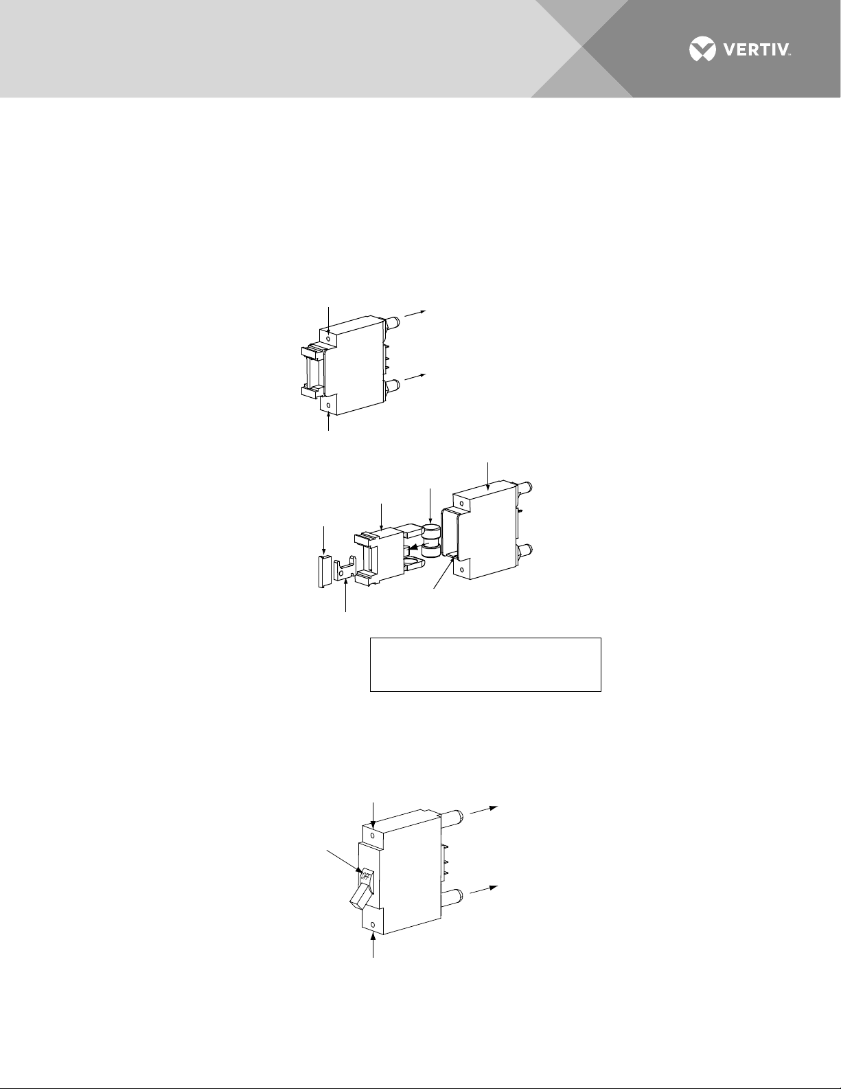
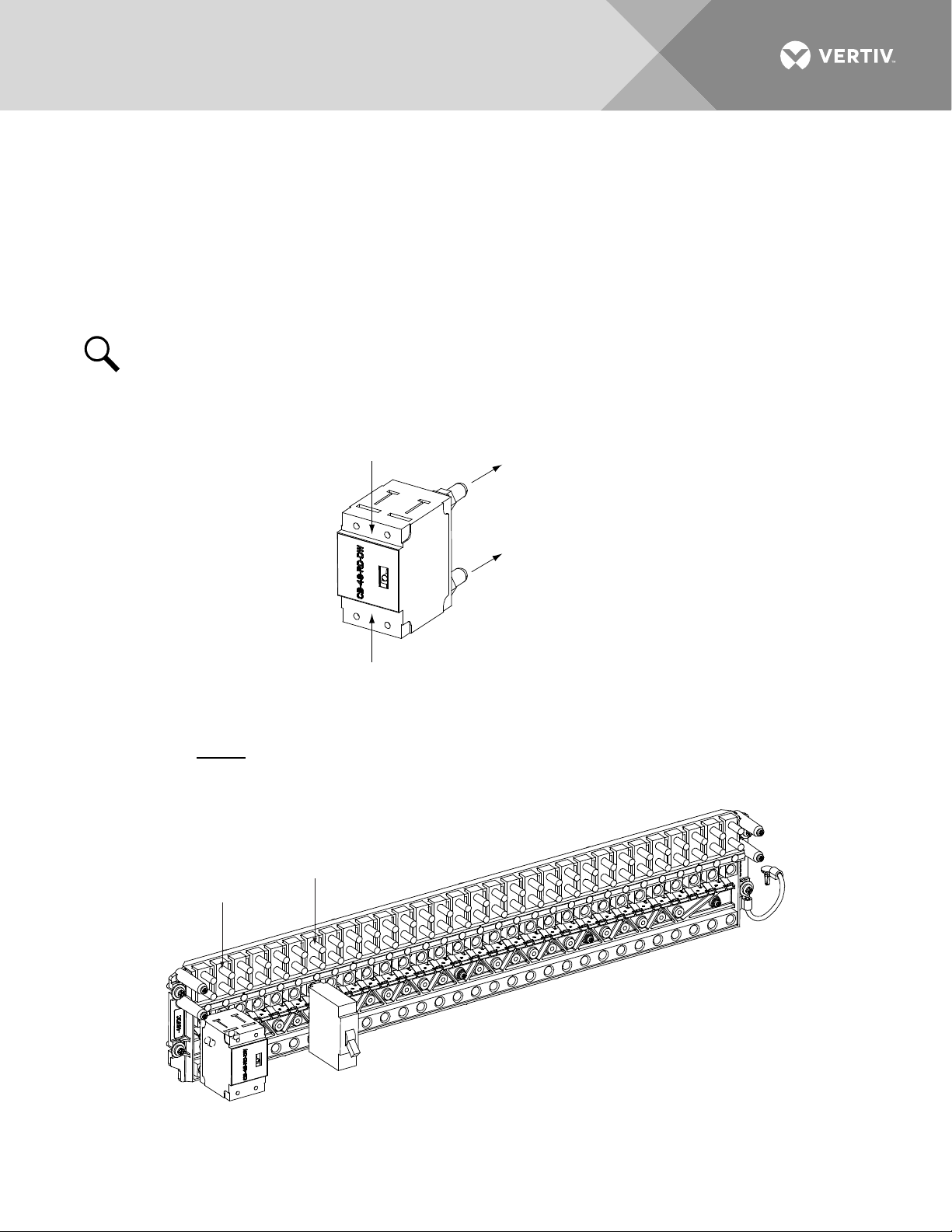
INSTALLING CIRCUIT BREAKERS AND FUSES
Load and battery distribution devices were factory-installed if ordered with the power system. If additional
installation is required, refer to Figure 1 through Figure 4. For detailed procedures, refer to Installing Circuit
Breakers and Fuses in the INSTALLING THE SYSTEM section of the Installation Instructions (IM582137000).
Figure 1:
Installing a Bullet Nose Type Fuseholder and TPS/TLS Fuse
Figure 2:
Vertiv | NetSure™ Quick Start Guide (QS582137000) | Rev. K
Installing a Bullet Nose Type Circuit Breaker
Page 13
13
Press in tabs to release
lug terminal busbars for
positions to be occupied
by GM
T Fuse Block.
Remove two lug terminal busbars
for positions to be occupied
by GM
T Fuse Block.
Plug in GM
T Fuse Block.
RTN Bar
GMT Fuse Block Installed View
1.
2.
3.
Secure GM
T Fuse Block Return Bar
at one location on the Distribution
Cabinet’s RTN bar
. Torque to 72 in-lbs.
4.
Figure 3:
Installing an Optional Bullet Nose Type 6-Position GMT Distribution Fuse Block (P/N 545333) in a
List 7 Distribution Cabinet
Vertiv | NetSure™ Quick Start Guide (QS582137000) | Rev. K
Page 14
14
P
lug
in GM
T Fuse Block.
D
i
s
t
r
i
b
u
t
i
o
n
P
a
n
e
l
C
o
v
e
r
2.
Connec
t su
ppli
ed j
ump
er fr
om
GM
T Fuse
Blo
ck t
o Ret
urn
Bar.
Torque to
72 in
-lb
s.
3.
R
e
mo
ve
t
wo
l
ug
te
r
mi
na
l
bu
sb
a
rs
f
or
po
s
it
io
n
s t
o b
e
oc
c
up
ie
d
by
G
MT
Fu
s
e B
lo
c
k.
Re
m
ov
e
pl
as
t
ic
bu
s
ba
r p
l
ug
s
fi
rs
t
. N
ot
e
t
ha
t
GM
T F
u
se
Bl
o
ck
c
an
on
l
y b
e i
n
st
al
l
ed
i
n l
oc
a
ti
on
s
wi
th
c
ut
ou
t
s
i
n
th
e
di
st
r
ib
ut
i
on
pa
n
el
co
v
er
.
1.
Figure 4:
Installing an Optional Bullet Nose Type 6-Position GMT Distribution Fuse Block (P/N 549017) in a
List 27 Distribution Cabinet
Vertiv | NetSure™ Quick Start Guide (QS582137000) | Rev. K
Page 15
15
DANGER
Ensure leads are connected to
proper polarity for the device
installed, either a Distribution
Device (load lead connection)
or a TVSS Device (ground
connection).
Load
Connection
TVSS
Device
Distribution
Device
1/4-20 Studs on 5/8” Centers
(Customer must supply or order hardware)
Maximum Lug Width: 0.625 inches.
TVSS
Ground
Connection
Distribution Device and TVSS Device
locations for reference only.
TVSS Device
Longer Side
to the Bottom
Shorter Side
to the Top
Insert these terminals
into corresponding sockets
on distribution panel.
INSTALL AND WIRE TRANSIENT VOLTAGE SURGE
SUPPRESSOR (TVSS) DEVICES
Transient Voltage Surge Suppressor (TVSS) devices were factory-installed if ordered with the power system. If
additional installation is required, refer to Figure 5. For detailed procedures, refer to Installation and Wiring of a
Transient Voltage Surge Suppressor (TVSS) Device in the INSTALLING THE SYSTEM section of the
Installation Instructions (IM582137000).
Figure 5:
NOTE!
The Transient Voltage Surge Suppressor (TVSS) device is to be installed on the -48V
distribution bus only.
Installation and Wiring of Transient Voltage Surge Suppressor (TVSS) Devices
Vertiv | NetSure™ Quick Start Guide (QS582137000) | Rev. K
Page 16

16
ELECTRICAL CONNECTIONS
Important Safety Instructions
DANGER! Adhere to the “Important Safety Instructions” presented at the front of this document.
Relay Rack / Cabinet Frame Grounding Connection
For relay rack / cabinet grounding requirements, refer to the current edition of the American National
Standards Institute (ANSI) approved National Fire Protection Association's (NFPA) National Electrical Code
(NEC), applicable local codes, and your specific site requirements.
Central Office Ground Connection
Landing points are provided on the battery return bus for a central office ground lead (see Figure 25 or Figure
26). For central office grounding requirements, refer to the current edition of the American National Standards
Institute (ANSI) approved National Fire Protection Association's (NFPA) National Electrical Code (NEC),
applicable local codes, and your specific site requirements.
Ground Connection to a Transient Voltage Surge Suppressor (TVSS) Devices
Refer to the procedure in “Install and Wire Transient Voltage Surge Suppressor (TVSS) Devices” on page 15.
AC Input and AC Input Equipment Grounding Connections to 588705300 Module
Mounting Shelf(s)
Refer to AC Input and AC Input Equipment Grounding Connections to 588705300 Module Mounting Shelf(s) in
MAKING ELECTRICAL CONNECTIONS section of the Installation Instructions (IM582137000) for a complete
procedure.
DANGER! Adhere to the “Important Safety Instructions” presented at the front of this document.
There are several options to provide AC inputs to the 588705300 module mounting shelf. See PD588705300.
1. For factory installed module mounting shelves without plug-in AC input connectors, AC input leads are
factory connected from the module mounting shelf AC input terminals to an AC input termination
assembly provided in the system/cabinet. Refer to the system/cabinet documentation for connection
details to the AC input termination assembly. Refer to the system/cabinet documentation for
recommended AC input branch circuit protection.
2. For a field installed module mounting shelf in a system with a List 27 distribution cabinet or if a List 7
distribution cabinet system is used in a relay rack and not a system cabinet, the module mounting shelf
is equipped with plug-in AC input connectors located on the rear of the shelf. AC input cable
assemblies with mating connectors are available (see Power Data Sheet PD588705300). Refer to
Power Data Sheet PD588705300 for recommended AC input branch circuit protection. See
PD588705300 and Figure 6.
Vertiv | NetSure™ Quick Start Guide (QS582137000) | Rev. K
Page 17
17
L2-N
Blue*
Ground
Green/Yellow*
L1
Brown*
* Color of AC Input
Cable Assembly Lead.
P/N 535232
P/N 547898
Nominal
120/208/240V
AC Input
AC Input Connector
(Cabinet Rear View)
AC input connections are made using the supplied
AC input cable assemblies connected here.
Rectifiers are numbered left to
right as viewed from the front.
AC Input for
Rectifier Positions
#5 and #6
AC Input for
Rectifier Positions
#1 and #2
AC Input for
Rectifier Positions
#3 and #4
Rear
Rear
Frame Ground Studs
Located Behind Cover
Figure 6:
AC Input Connections to Module Mounting Shelf with Plug-In AC Input Connectors
Vertiv | NetSure™ Quick Start Guide (QS582137000) | Rev. K
Page 18
18
External Alarm, Reference, Monitoring, and Control Connections
Refer to External Alarm, Reference, Monitoring, and Control Connections in MAKING ELECTRICAL
CONNECTIONS section of the Installation Instructions (IM582137000) for complete procedures.
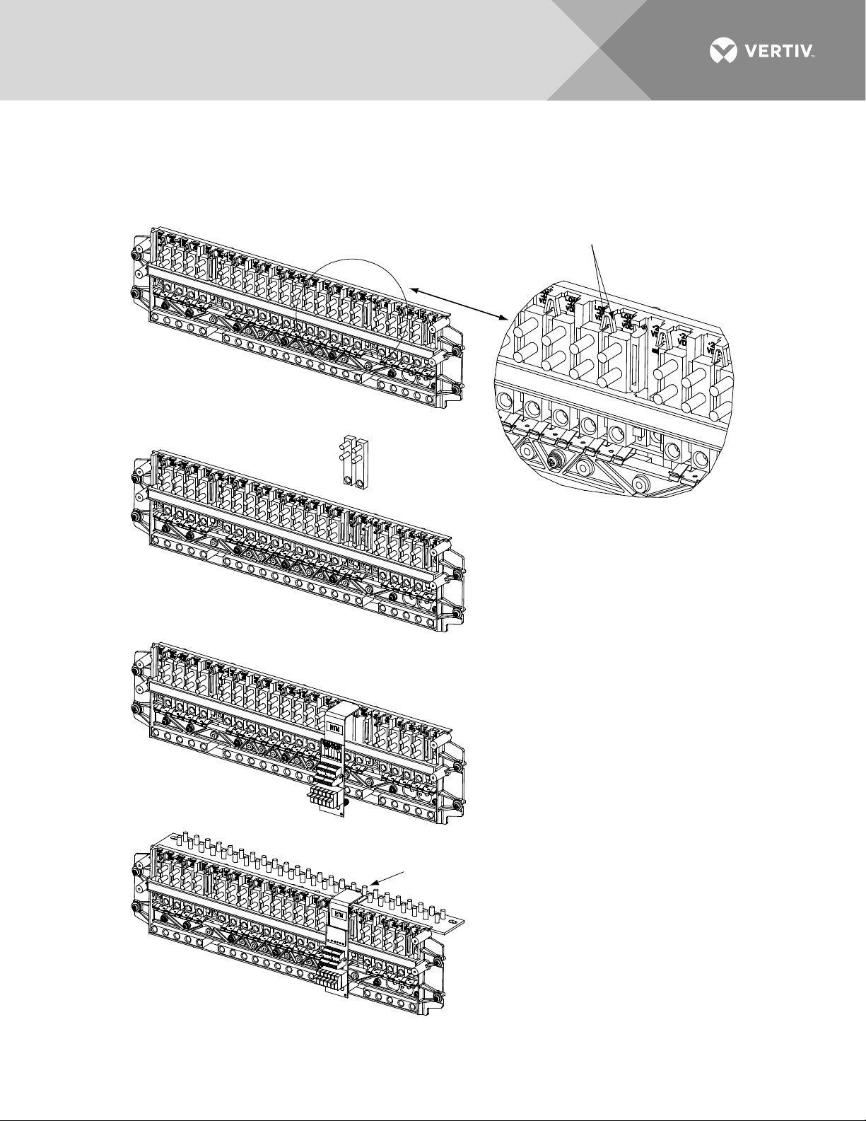
Circuit Card and Connector Locations
Refer to Figure 7 or Figure 8.
Figure 7:
Circuit Card and Connector Locations - List 27 Distribution Cabinet
Vertiv | NetSure™ Quick Start Guide (QS582137000) | Rev. K
Page 19
19
Figure 8:
Circuit Card and Connector Locations - List 7 Distribution Cabinet
Vertiv | NetSure™ Quick Start Guide (QS582137000) | Rev. K
Page 20

20
Front
System Interface Board
J3 on System Interface Board
RS485 Connection
J3-1: RS485+
J3-2: RS485-
J2
CAN
J1
J2
J3
J4
J5
1
1
555484
0 0 0 X X X X X
AX XX X X X X X
1
J4 on System Interface Board
Selects to power Controller
from “Battery Power” or not.
No
Battery
Pwr
Battery
Pwr
Shorting Jumper
Top View
System Interface Circuit Card Connections (if required) (List 27 Distribution Cabinet Only)
The System Interface Circuit Card provides connections for the following. Refer to Figure 7 for circuit card
location. Refer to Figure 9 for connections location.
• RS-485 (used for communication with SM modules)
Figure 9:
System Interface Circuit Card Connections
Vertiv | NetSure™ Quick Start Guide (QS582137000) | Rev. K
Page 21

21
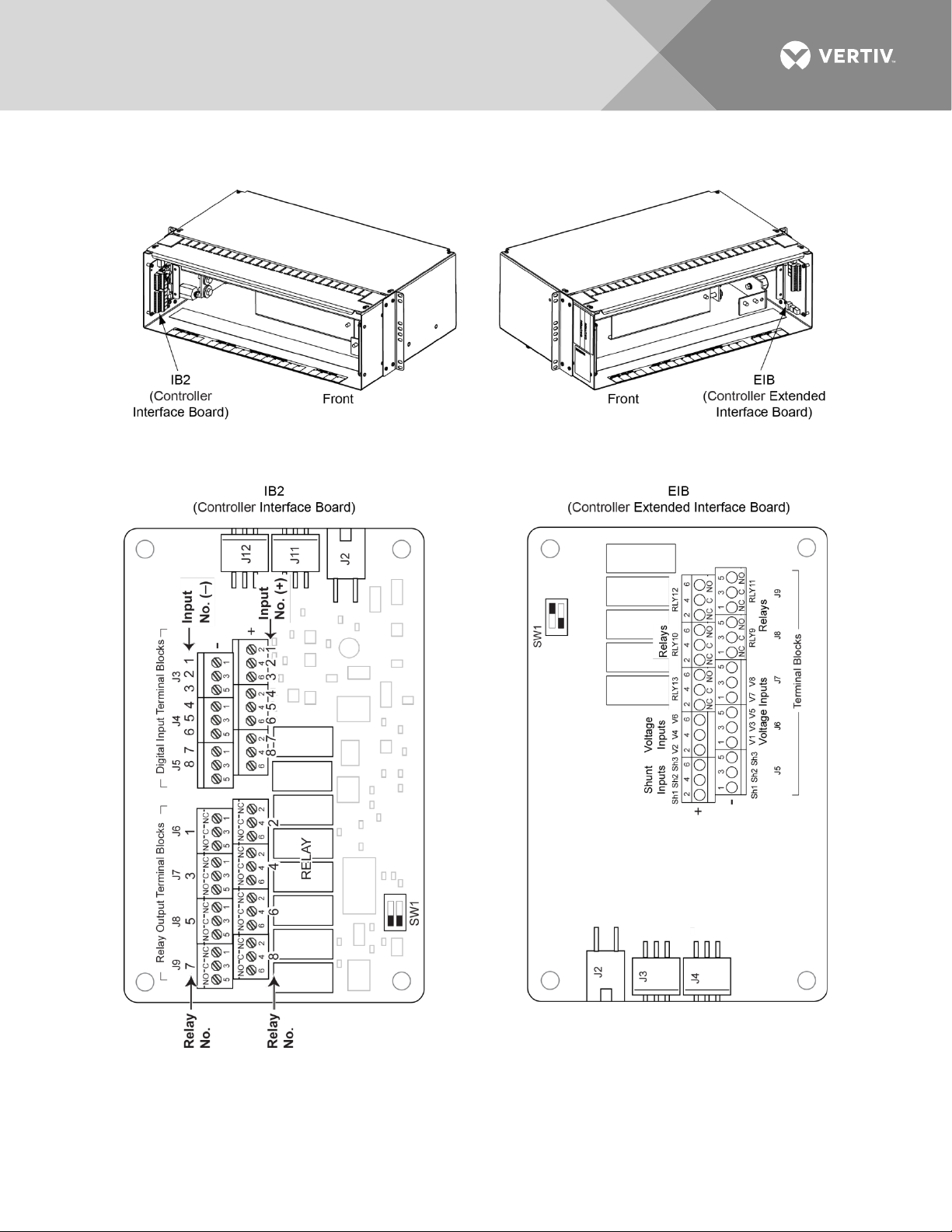
IB2 (Controller Interface Board) Connections (if required)
The IB2 (Controller Interface Board) provides connection points for digital inputs, programmable relay outputs,
and temperature probes. The IB2 interface board is mounted inside the distribution cabinet. Refer to Figure 7
or Figure 8.
Digital Inputs and Programmable Relay Outputs
Digital input and relay output leads are connected to screw-type terminal blocks located on the IB2.
Recommended torque for these connections is 2.2 in-lbs. Refer to Figure 10 for terminal locations. Refer to
Table 1 and Table 2 for pin-out information.
Digital Inputs
Connect up to eight (8) digital inputs to the IB2. Note that you must supply both paths for the digital input
(either a positive or negative signal and the opposite polarity return path). Observe proper polarity. Refer to
Figure 10 for terminal locations and Table 1 for pin-out information.
The digital inputs can be programmed to provide an alarm when the signal is applied (HIGH) or removed
(LOW). Refer to the Controller Instructions (UM1M820BNA or UM1M830BNA) for programming information.
Digital Input Ratings: Refer to the following.
a) Maximum Voltage Rating: 60 VDC.
b) Active High: > 19 VDC.
c) Active Low: < 1 VDC.
The digital inputs may be preprogrammed for specific functions. Refer to the configuration drawing (Cdrawing) supplied with your system for your system’s specific configuration.
ESTOP Function
If an ESTOP switch is wired to the IB2-1 Controller Interface Board, customer-furnished system ground applied
to terminal DI8+ activates the ESTOP function. The ESTOP function shuts down and locks out the rectifiers,
shuts down and locks out the optional -48 VDC to +24 VDC converters, and opens the optional low voltage
disconnect (LVD) contactors (battery and load type). If the system has battery connected and does not
contain a battery LVD or the controller power option is set to Battery Pwr (jumper J4 on the system interface
board is set to Battery Pwr), the controller will remain operational. If the system does not contain battery or
load LVD(s) and has battery connected, the loads will be sustained by the battery voltage.
For Systems NOT Containing a Battery LVD: When the ESTOP signal is removed, LVD contactors (battery and
load type) will close after the “LVD Reconnect Delay” has elapse (customer configurable via the controller) if
battery voltage is present on the bus. Rectifiers and -48 VDC to +24 VDC converters will remain off. The
rectifiers will restart when the input power is removed and restored after 30 seconds or more (until the LEDs on
the modules extinguish). To restart the -48 VDC to +24 VDC converters: remove the converter, wait 30
seconds or more (until the LEDs on the converter extinguish), then re-insert the converter.
For Systems Containing a Battery LVD: When the ESTOP signal is removed, LVD contactors (battery and load
type) will remain open. Rectifiers and -48 VDC to +24 VDC converters will remain off. The rectifiers will restart
when the input power is removed and restored after 30 seconds or more (until the LEDs on the modules
extinguish). When the rectifiers restart, LVD contactors (battery and load type) will close after the “LVD
Reconnect Delay” has elapse (customer configurable via the controller) and the -48 VDC to +24 VDC
converters will restart.
Vertiv | NetSure™ Quick Start Guide (QS582137000) | Rev. K
Page 22

22
NOTE!
If a customer-furnished method to disconnect the input power to the system is not provided, the
rectifiers will stay locked OFF until the input power is recycled. If the ESTOP signal is removed without
recycling the input power, the rectifiers will remain off and have a local alarm visible on the module. The
ESTOP alarm from the controller will extinguish. The controller will not issue an alarm for this condition.
Programmable Relay Outputs
The IB2 provides eight (8) programmable alarm relays with dry Form-C contacts. Connect up to eight (8) relay
outputs to the IB2. Refer to Figure 10 for terminal locations and Table 2 for pin-out information.
Refer to the Controller Instructions (UM1M820BNA or UM1M830BNA) for programming information.
Relay Ratings: Refer to the following.
a) Steady State: 0.5 A @ 60 VDC; 1.0 A @ 30 VDC.
b) Peak: 3 A @ 30 VDC.
The relays may be preprogrammed for specific functions. Refer to the configuration drawing (C-drawing)
supplied with your system for your system’s specific configuration.
Temperature Probes
NOTE!
Each temperature probe consists of two or three pieces that plug together to make a complete
probe. See SAG582137000 for part numbers and descriptions.
Temperature probes are connected to the IB2 (Controller Interface Board) and/or EIB (Controller Extended
Interface Board) mounted inside the distribution cabinet.
Up to two (2) temperature probes can be connected to the IB2. Up to two (2) additional temperature probes
can be connected to the EIB. Any combination of the four (4) temperature probes can be programmed to
monitor ambient temperature and/or battery temperature. A temperature probe set to monitor battery
temperature can also be used for the rectifier battery charge temperature compensation feature, or the battery
charge temperature compensation feature can be programmed to use the average or highest value of all
battery temperature probes. The battery charge temperature compensation feature allows the controller to
automatically increase or decrease the output voltage of the system to maintain battery float current as battery
temperature decreases or increases, respectively. Battery life can be extended when an optimum charge
voltage to the battery with respect to temperature is maintained. A temperature probe set to monitor battery
temperature can also be used for the BTRM (Battery Thermal Runaway Management) feature. The BTRM
feature lowers output voltage when a high temperature condition exists to control against battery thermal
runaway.
The temperature sensor end of the probe contains a tab with a 5/16” clearance hole for mounting.
A temperature probe programmed to monitor battery temperature should be mounted on the negative post of
a battery cell to sense battery temperature. A temperature probe used for battery charge temperature
compensation and/or BTRM (Battery Thermal Runaway Management) should also be mounted on the negative
post of a battery cell. A temperature probe programmed to monitor ambient temperature should be mounted
in a convenient location, away from direct sources of heat or cold.
Vertiv | NetSure™ Quick Start Guide (QS582137000) | Rev. K
Page 23

23
Figure 10:
IB2 (Interface Board) Connections
Vertiv | NetSure™ Quick Start Guide (QS582137000) | Rev. K
Page 24

24
Table 1:
Programmable Digital Inputs – IB2
Programmable
Digital Input
1
2
3
4
5
6
7
8
-- J5-5
-- J5-6
IB2
Pin No.
Factory
Wiring
J3-2 +
J3-1 –
J3-4 +
J3-3 –
J3-6 +
J3-5 –
J4-2 +
J4-1 –
J4-4 +
J4-3 –
J4-6 +
The digital inputs may
be preprogrammed for
specific functions and
have factory wiring
connected. Refer to the
configuration drawing
(C-drawing) supplied
with your system for
your system’s specific
configuration.
J4-5 –
J5-2 +
J5-1 –
J5-4 +
(to customer
ESTOP switch)
J5-3 – -48 VDC
not used not used not used
Default Digital
Input Function
The digital inputs may
be preprogrammed for
specific functions.
Refer to the
configuration drawing
(C-drawing) supplied
with your system for
your system’s specific
configuration.
ESTOP
Customer Defined
Digital Input Function
NOTE!
-48V is factory wired to the Digital Input #8 (-) terminal for your convenience and function
predefined for ESTOP. Customer-furnished system ground applied to terminal Digital Input #8 (+)
activates the ESTOP function. See “ESTOP Function” on page 21.
Vertiv | NetSure™ Quick Start Guide (QS582137000) | Rev. K
Page 25

25
Table 2:
Programmable Relay Outputs – IB2
Programmable
Relay Output
IB2
Pin No.
NO J6-5
1
NC J6-1
NO J6-6
2
NC
J6-4
J6-2
NO J7-5
3
NC J7-1
NO J7-6
4
NC J7-2
NO J8-5
5
NC J8-1
NO J8-6
6
NC
J8-4
J8-2
NO J9-5
7
NC J9-1
NO J9-6
8
J9-4
NC J9-2
Alarms Assigned to this
Relay (Default)
The relays may be
preprogrammed for specific
functions. Refer to the
configuration drawing (Cdrawing) supplied with your
system for your system’s
specific configuration.
Alarms Assigned to this
Relay (Custom)
COM J6-3
COM
COM J7-3
COM J7-4
COM J8-3
COM
COM J9-3
COM
NOTE!
The controller’s relay assigned to “Critical Summary” alarm (relay 1 by default) will operate in the
“Fail Safe Mode”. “Fail Safe Mode” means Relay 1 is de-energized during an alarm condition, opening the
contacts between the C and NO terminals, and closing the contacts between the C and NC terminals.
The controller’s remaining 7 relays energize during an alarm condition, closing the contacts between the
C and NO terminals, and opening the contacts between the C and NC terminals.
Vertiv | NetSure™ Quick Start Guide (QS582137000) | Rev. K
Page 26

26
Battery Block Monitoring
Midpoint Monitoring
EIB (Controller Extended Interface Board) Connections (if required)
The EIB (Controller Extended Interface Board) provides additional connection points for current and voltage
inputs, programmable relay outputs, and temperature probes. The EIB extended interface board is mounted
inside the distribution cabinet. Refer to Figure 7 or Figure 8.
Current Inputs, Voltage Inputs, and Programmable Relay Outputs
Current input, voltage input, and relay output leads are connected to screw-type terminal blocks located on the
EIB. Recommended torque for these connections is 2.2 in-lbs. Refer to Figure 12 for terminal locations. Refer
to Table 3, Table 4, and Table 5 for pin-out information.
Current Inputs
Connect up to three (3) shunt inputs to the EIB. Observe proper polarity. Refer to Figure 12 for terminal
locations and Table 3 for pin-out information.
Refer to the Controller Instructions (UM1M820BNA or UM1M830BNA) and program the shunt input parameters
found in the EIB menu.
NOTE!
The shunt needs to be installed in the hot (-48V) bus. Connect the plus side of the shunt to the
positive shunt input on the EIB. Connect the negative side of the shunt to the negative shunt input on
the EIB.
Voltage Inputs for Battery Block and Battery Midpoint Monitoring
The controller can monitor battery blocks (12V blocks) or midpoint battery voltage of battery strings connected
to the EIB. The EIB provides a total of eight (8) DC voltage inputs for these connections. An alarm is issued
when either battery block voltage or battery midpoint voltage is abnormal. Refer to Figure 12 for terminal
locations and Table 4 for pin-out information.
Refer to Figure 11 for connection details. Refer to the Controller Instructions (UM1M820BNA or UM1M830BNA)
and program the following parameters.
NOTE!
When using Battery Block Monitoring, you must make connections to all blocks.
•
Voltage Type: Set to “48 (Block 4)”. This selects the EIB to monitor up to two (2) 48V battery strings
with four (4) 12V blocks per string.
BlockVDiff(12V): This menu item appears if “48 (Block 4)” is selected above. Set to the alarm threshold
for battery block monitoring per site requirements. The controller issues an alarm when any block
voltage of any battery string has an abnormal value. The alarm is issued when the difference between
any block voltage and a reference voltage is greater than the value of the block voltage difference
setting.
Block In-Use: Set to the number of 12V battery blocks being used.
•
Voltage Type: Set to “Midpoint”. This selects the EIB to monitor the midpoint voltage of up to eight (8)
battery strings.
BlockVDiff(Mid): This menu item appears if “Midpoint” is selected above. Set to the alarm threshold for
battery midpoint monitoring per site requirements. The controller issues an alarm when any battery
Vertiv | NetSure™ Quick Start Guide (QS582137000) | Rev. K
Page 27

27
midpoint voltage of any battery string has an abnormal value. The alarm is issued when the difference
between any battery midpoint voltage and a reference voltage is greater than the value of the block
voltage difference setting.
Block In-Use: Set to number of 12V battery blocks being used.
Programmable Relay Outputs
The EIB provides five (5) programmable alarm relays with dry Form-C contacts. Connect up to five (5) relay
outputs to the IB2. Refer to Figure 12 for terminal locations and Table 4 for pin-out information.
Refer to the Controller Instructions (UM1M820BNA or UM1M830BNA) for programming information.
Relay Ratings: Refer to the following.
a) Steady State: 0.5 A @ 60 VDC; 1.0 A @ 30 VDC.
b) Peak: 3 A @ 30 VDC.
The relays may be preprogrammed for specific functions. Refer to the configuration drawing (C-drawing)
supplied with your system for your system’s specific configuration.
Temperature Probes
Temperature probes can be connected to the EIB (Controller Extended Interface Board) mounted inside the
distribution cabinet. Refer to “Temperature Probes” on page 22.
Vertiv | NetSure™ Quick Start Guide (QS582137000) | Rev. K
Page 28

28
Figure 11:
Sample Battery Block or Battery Midpoint Monitoring Connections
Vertiv | NetSure™ Quick Start Guide (QS582137000) | Rev. K
Page 29

29
Figure 12:
EIB (Extended Interface Board) Connections
Vertiv | NetSure™ Quick Start Guide (QS582137000) | Rev. K
Page 30

30
Shunt Input
EIB
Pin No.
Factory
Wiring
Default
Function
Customer
Defined Function
Voltage Input
EIB
Pin No.
Default
Function
Table 3:
Sh1
Sh2
Sh3
Table 4:
Shunt Inputs – EIB
J5-2 + --
J5-1 – --
J5-4 + --
J5-3 – --
J5-6 + --
J5-5 – --
Voltage Inputs – EIB
1 J6-1
2 J6-2
3 J6-3
4 J6-4
5 J6-5
6 J6-6
7 J7-1
8 J7-3
none
none
none
Battery
Block
Monitoring
Vertiv | NetSure™ Quick Start Guide (QS582137000) | Rev. K
Page 31

31
Programmable
Relay Output
EIB
Pin No.
Alarms Assigned to this
Relay (Default)
Alarms Assigned to this
Relay (Custom)
Table 5:
Programmable Relay Outputs – EIB
NO J8-5
9
NC J8-1
NO J8-6
10
NC J8-2
NO J9-5
11
NC J9-1
NO J9-6
The relays may be
preprogrammed for specific
functions. Refer to the
configuration drawing (Cdrawing) supplied with your
system for your system’s
specific configuration.
12
NC
J9-2
NO J7-6
13
NC J7-2
COM J8-3
COM J8-4
COM J9-3
COM J9-4
COM J7-4
NOTE!
The relays energize during an alarm condition, closing the contacts between the C and NO
terminals, and opening the contacts between the C and NC terminals.
Vertiv | NetSure™ Quick Start Guide (QS582137000) | Rev. K
Page 32

32
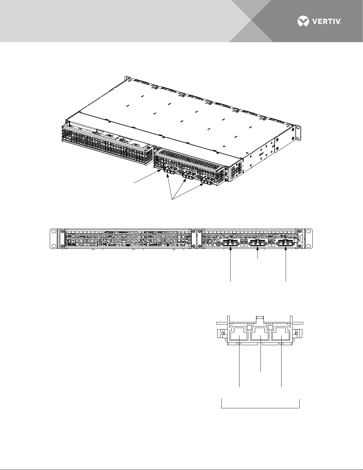
Controller Ethernet Connection (if required)
The controller provides a Web Interface via an Ethernet connection to a TCP/IP network. This interface can be
accessed locally on a computer or remotely through a network. An RJ-45 10BaseT jack is provided on the front
of the controller for connection into a customer's network. This jack has a standard Ethernet pin configuration
scheme, twisted pair. Refer to Figure 13 for location and Table 6 for pin outs. Use shielded Ethernet cable
(grounded at both ends). Note that the controller’s RJ-45 jack is connected to chassis ground. Refer to the
Controller Instructions (UM1M820BNA or UM1M830BNA) for operational details.
NOTE!
You can access the Web pages of the power system locally by using a "crossover" or “straight”
cable connected directly between your PC and the controller.
WARNING! The intra-building port(s) of the equipment or subassembly is suitable for connection to
intra-building or unexposed wiring or cabling only. The intra-building port(s) of the equipment or
subassembly MUST NOT be metallically connected to the interfaces that connect to the OSP or its
wiring. These interfaces are designed for use as intra-building interfaces only (Type 2 or Type 4 ports as
described in GR-1089-CORE, Issue 4) and require isolation from the exposed OSP cabling. The addition
of Primary Protectors is not sufficient protection in order to connect these interfaces metallically to OSP
wiring.
The intra-building port (RJ-45) of the equipment or subassembly must use shielded intra-building
cabling/wiring that is grounded at both ends.
Figure 13:
Controller Ethernet Port
Vertiv | NetSure™ Quick Start Guide (QS582137000) | Rev. K
Page 33

33
1
Tx+
Write Signal +
2
Tx-
Write Signal -
3
Rx+
Read Signal +
4
--
no connection
5
--
no connection
6
Rx-
Read Signal -
7
--
no connection
8
--
no connection
Table 6:
Controller RJ-45 Ethernet Port Pin Configuration
Port Pin
Number
Name Definition
Connecting a Device or System to the Controller’s CAN Bus (List 27 Distribution Cabinet Only)
A supporting device or system may be connected to the Controller’s CAN Port located inside a List 27
Distribution Cabinet. Refer to Figure 7 for location. Refer to Table 7 for pin-outs. Refer also to the external
device’s or system’s instruction manual.
General Procedure
1. Remove the CAN termination plug from the CAN Port connector (see Figure 7 for location). Connect
the device or system to the Controller’s CAN port. Refer to Table 7 for pin-outs. Ensure that the last
device on the controller’s CAN bus has a CAN termination plug. Refer also to the external device’s or
system’s instruction manual.
Optional SM-Temp Module
The analog output of the SM-Temp Module may be connected to a controller temperature port input. In lieu of
connecting the analog output of the SM-TEMP module to a controller temperature port input, the SM-TEMP
module can simply be connected at the end of the Controller’s CAN bus (for system’s equipped with an ACU+,
requires ACU+ version 3.02 or later). Refer to the SM-Temp Module Instructions (UM547490) for details.
CAN Bus Procedure
1. Remove the CAN termination plug from the CAN Port connector (see Figure 7 for location). Connect
the SM-Temp Module CAN bus to the CAN Port connector. Refer to Table 7 for pin-outs. Ensure the
last SM-Temp Module (or if only one) has a CAN termination strap as shown in the SM-Temp Module
Instructions (UM547490).
Vertiv | NetSure™ Quick Start Guide (QS582137000) | Rev. K
Page 34

34
2
CAN H
TB1-3 (CAN H)
4
--
-- 5 --
-- 6 --
--
8
--
--
Table 7:
CAN Port Connections
Pin Number Function
Controller CAN
Port (RJ-45)
SM-Temp Module
CAN Port
Pin Number
1 CAN L TB1-5 (CAN L)
3 -- --
7 -- --
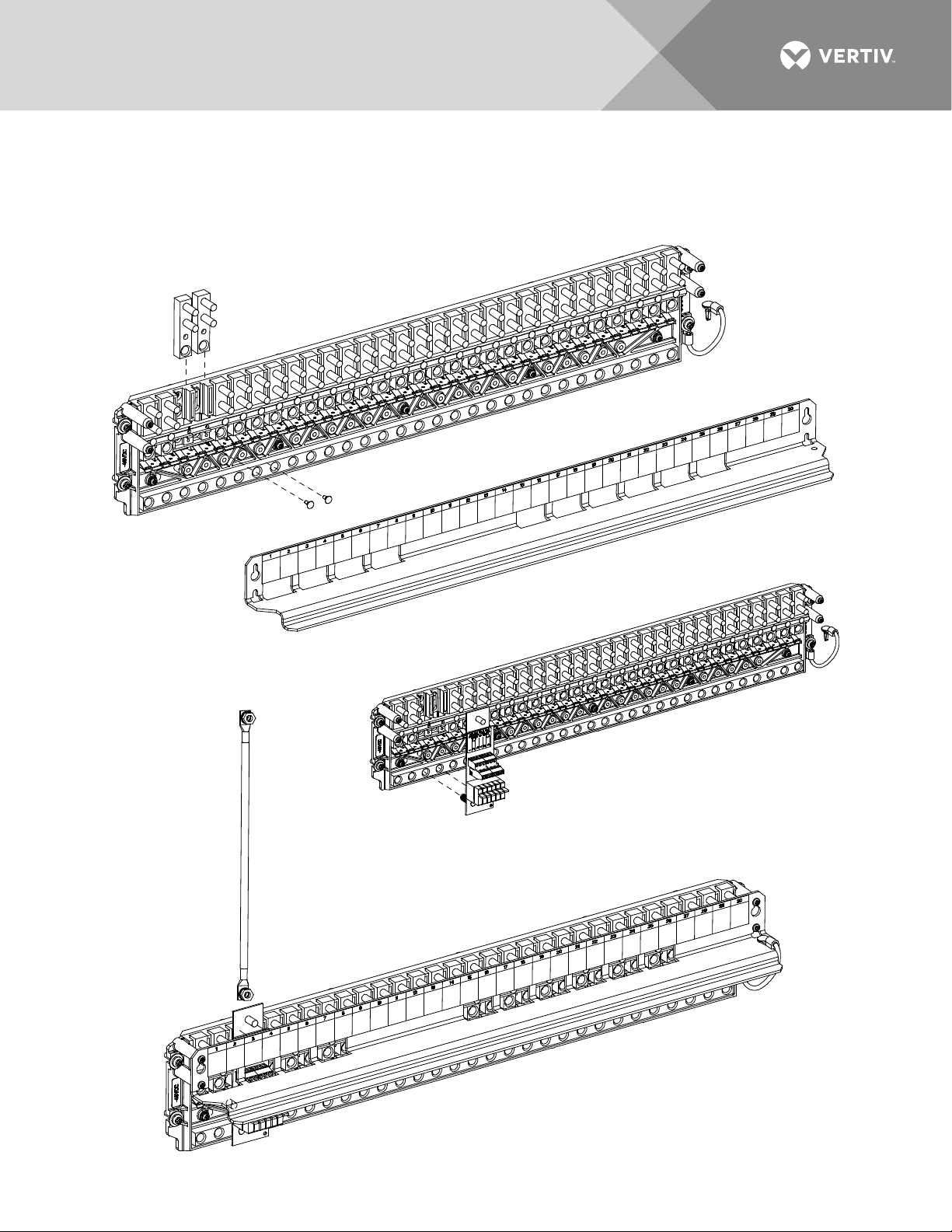
Load Connections to a List 27 Distribution Cabinet
Load leads are connected to the individual load busbars located on the distribution panels (refer to Figure 14).
Load return leads are connected to separate return busbars located at the top of the distribution cabinet (refer
to Figure 15). Refer to Figure 17 through Figure 22 for illustrations of the available distribution panels.
Refer to Figure 16 if an optional “Bullet Nose Type 6-Position GMT Distribution Fuse Block” is furnished.
Recommended Torque
• 72 in-lbs for 1/4-inch hardware (when using standard flat and lock washer).
Vertiv | NetSure™ Quick Start Guide (QS582137000) | Rev. K
Page 35

35
-
4
8V
D
i
s
t
r
i
b
ut
i
on
+
2
4V
D
i
s
tr
i
bu
ti
on
Load Connections
Load Connections (-48V DC)
1/4-20 Studs on 5/8” Centers
(Customer must supply or order hardware)
Maximum Lug Width: 0.625 inches.
1/4-20 Studs on 5/8” Centers
(Customer must supply or order hardware)
Maximum Lug Width: 0.625 inches.
Shields removed in
illustration for clarity only.
Top Distribution Row
Bottom Distribution Row
Distribution rows shown for sample only.
Refer to the Distribution Panel illustrations
located in this section.
Load Return Bus
(see next page)
Cable Tie Points
Figure 14:
Load Side Connections in a List 27 Distribution Cabinet
Vertiv | NetSure™ Quick Start Guide (QS582137000) | Rev. K
Page 36

36
Maximum Lug Width: 0.625 inches.
L
Figure 15:
Load Return Side Connections in a List 27 Distribution Cabinet
Cable T
ie
P
oi
n
ts
Top Di
s
tr
ib
u
ti
o
n R
(s
ee
p
re
vious page)
Bottom Distribution Row
(see previous page)
Shields removed in
illustration for clarity only.
Load Return Bus
ow
Fron
Loa
d R
e
tu
rn
B
us
t
oad
Return B
Vertiv | NetSure™ Quick Start Guide (QS582137000) | Rev. K
us
1
/4-20 Studs on 5/8” Centers
(Customer must supply o
Rear
r order additional hardware)
Page 37

37
Load Return Leads
P/N 549017
Load Leads
Wire Size Capacity: 26-14 AWG.
Recommended Torque: 4.5 in-lbs.
21.4A maximum capacity per block.
Maximum GMT fuse size is 15A.
Load Connections (-48V DC)
Maximum Lug Width: 0.625 inches.
1/4-20 Studs on 5/8” Centers
(Customer must supply or order hardware)
Observe proper
polarity when making
load connections.
WARNING!
Caution: A circuit breaker or fuse with a rating
of 80A or greater SHALL HAVE an empty
mounting position between it and any
other overcurrent protective device.
Figure 16:
Load Connections to GMT Fuse Block (P/N 549017) in a List 27 Distribution Cabinet
Load Connections to Single Voltage Distribution Panels in a List 27 Distribution Cabinet
Figure 17:
List AC Load Connections
(30) -48 VDC Bullet/TPS/TLS Circuit Breaker/Fuse Positions
Vertiv | NetSure™ Quick Start Guide (QS582137000) | Rev. K
Page 38

38
-
4
8
V
D
i
s
t
r
i
b
u
t
i
o
n
+
2
4
V
D
i
s
t
r
i
b
u
t
i
o
n
Load Connections
Maximum Lug Width: 0.625 inches.
1/4-20 Studs on 5/8” Centers
(Customer must supply or order hardware)
Observe proper
polarity when making
load connections.
WARNING!
Caution: A circuit breaker or fuse with a rating
of 80A or greater SHALL HAVE an empty
mounting position between it and any
other overcurrent protective device.
-
4
8V
D
i
s
tr
i
bu
ti
on
+
2
4
V
D
i
s
t
r
i
bu
ti
o
n
L
oad Con
nections
Maximum Lug Width: 0.62
5 in
che
s.
1/4-20 Stu
ds o
n 5/
8” Cent
ers
(C
ust
omer
must s
upp
ly or order hardware)
Observe proper
po
lar
ity
when making
load conne
ction
s.
WARNING!
Caution: A circuit breake
r or fuse with a rating
of 80A or g
reater SHALL HAVE an empty
mounting position b
etween it and any
other overcurrent protect
ive device.
Load Connections to Dual Voltage Distribution Panels in a List 27 Distribution Cabinet
Figure 18:
List DH Load Connections
(21) -48 VDC Bullet/TPS/TLS Circuit Breaker/Fuse Positions and
(8) +24 VDC Bullet/TPS/TLS Circuit Breaker/Fuse Positions
Figure 19:
List DI Load Connections
(17) -48 VDC Bullet/TPS/TLS Circuit Breaker/Fuse Positions and
(12) +24 VDC Bullet/TPS/TLS Circuit Breaker/Fuse Positions
Vertiv | NetSure™ Quick Start Guide (QS582137000) | Rev. K
Page 39

39
-
48
V
D
i
s
tr
i
b
u
ti
o
n
+24
V
D
i
s
tr
i
b
u
ti
o
n
Load Connections
Maximum Lug Width
:
0.
62
5
in
ch
e
s.
1/4-20 Studs on 5/8” C
en
t
er
s
(
C
ustomer must supply or order hardware)
Observe pro
p
er
polarity when making
load connec
t
io
ns
.
WARNING!
Caution: A circuit breaker o
r fus
e wi
th a
ra
ti
ng
of 80A or greater SHALL H
AVE a
n em
pty
mounting position between i
t and
any
other overcurrent protective
devi
ce.
-
48
V
D
i
s
tr
i
b
u
ti
o
n
+
2
4
V
D
i
s
t
r
i
b
ut
i
o
n
Load Connections
Maximum Lug Width: 0.625 inches.
1/4-20 Studs on 5/8” Centers
(Customer must supply or order hardware)
Observe proper
polarity when making
load connections.
WARNING!
Caution: A circuit breaker or fuse with a rating
of 80A or greater SHALL HAVE an empty
mounting position between it and any
other overcurrent protective device.
Figure 20:
List DJ Load Connections
(13) -48 VDC Bullet/TPS/TLS Circuit Breaker/Fuse Positions and
(16) +24 VDC Bullet/TPS/TLS Circuit Breaker/Fuse Positions
Figure 21:
List DK Load Connections
(9) -48 VDC Bullet/TPS/TLS Circuit Breaker/Fuse Positions and
(20) +24 VDC Bullet/TPS/TLS Circuit Breaker/Fuse Positions
Vertiv | NetSure™ Quick Start Guide (QS582137000) | Rev. K
Page 40

40
-
48
V
D
i
s
tr
i
b
u
ti
o
n
+24
V
D
i
s
t
r
i
b
ut
i
o
n
Load Connections
Maximum Lug Width: 0.625 inches.
1/4-20 Studs on 5/8” Centers
(Customer must supply or order hardware)
Observe proper
polarity when making
load connections.
WARNING!
Caution: A circ
uit breaker or
f
us
e with
a rating
of 80A or greater SHALL HAVE an empty
m
ounting position between it and any
other ov
er
c
ur
rent
protective device.
Figure 22:
List DL Load Connections
(5) -48 VDC Bullet/TPS/TLS Circuit Breaker/Fuse Positions and
(24) +24 VDC Bullet/TPS/TLS Circuit Breaker/Fuse Positions
Vertiv | NetSure™ Quick Start Guide (QS582137000) | Rev. K
Page 41

41
Maximum Lug Width: 0.625 inches.
1/4-20 Studs on 5/8” Centers
(Customer must supply or order hardware)
-48V Load Distribut ion
-48V Battery
+24V Load Distribu tion
Front
Return Bus
(Battery Return and
Load Return Connections)
1/4-20 Studs on 5/8” Centers
(Customer must supply or order additional hardware)
Maximum Lug Width: 0.625 inches.
Return Bus
Shields removed in
illustration for clarity only.
Caution: A -48 VDC load distribution
circuit breaker or fuse with a rating of
80A or greater SHALL HAVE an empty
mounting position between it and any
other overcurrent protective device.
Load Connections to a List 7 Distribution Cabinet
Load leads are connected to the individual load busbars located on the distribution panel (refer to Figure 23).
Load return leads are connected to the return busbar located at the top of the distribution cabinet (refer to
Figure 23).
Refer to Figure 24 if an optional “Bullet Nose Type 6-Position GMT Distribution Fuse Block” is furnished.
Recommended Torque
• 72 in-lbs for 1/4-inch hardware (when using standard flat and lock washer).
Figure 23:
Load and Load Return Connections in a List 7 Distribution Cabinet
Vertiv | NetSure™ Quick Start Guide (QS582137000) | Rev. K
Page 42

42
Figure 24
: Load Connections to GMT Fuse Block (P/N 545333) in a List 7 Distribution Cabinet
Vertiv | NetSure™ Quick Start Guide (QS582137000) | Rev. K
Page 43

43
Battery
(Return Side)
Busbar
Central
Office
Ground
Battery
(Load Side)
Busbar
GND RTN
-48V SUPPLY
BATTERYAND BATTERY RETURN CONNECTIONS
3/8-16 Studs on 1” Centers
(Customer must supply additional hardware)
Maximum Lug Width: 1.88 inches.
Rear View (rear cover shields removed)
Battery Connections to a List 27 Distribution Cabinet
Input battery leads are connected to the battery busbar and battery return busbar. Customer must supply lug
mounting hardware. Refer to Figure 25.
Important Safety Instructions
DANGER! Adhere to the “Important Safety Instructions” presented at the front of this document.
WARNING! Observe proper polarity when making battery connections.
Recommended Torques
• 300 in-lbs for 3/8-inch hardware (when using standard flat and lock washer).
• 180 in-lbs for 3/8-inch hardware (when using a Belleville lock washer).
Figure 25:
Battery and Central Office Ground Connections in a List 7 Distribution Cabinet
Vertiv | NetSure™ Quick Start Guide (QS582137000) | Rev. K
Page 44

44
Central Offic e Ground
GND RTN
-48V SUPPLY
Maximum Lug Width: 0.625 inches.
1/4-20 Studs on 5/8” Centers
(Customer must supply or order hardw are)
-48V Load Distribut ion
-48V Battery
+24V Load Distribut ion
Front
Return B us
(Battery Return and
Load Return Connections)
1/4-20 Studs on 5/8” Centers
(Customer must supply or order additional hardware)
Maximum Lug Width: 0.625 inches.
Return B us
Shields removed in
illustration for clarity only.
Battery Connections to a List 7 Distribution Cabinet
Input battery leads are connected to the individual battery busbars located on the distribution panel. Battery
return leads are connected to the return busbar located at the top of the distribution cabinet. Customer must
provide (or order) lug mounting hardware. Refer to Figure 26.
Important Safety Instructions
DANGER! Adhere to the “Important Safety Instructions” presented at the front of this document.
WARNING! Observe proper polarity when making battery connections.
Recommended Torques
• 72 in-lbs for 1/4-inch hardware (when using standard flat and lock washer).
Figure 26:
Battery and Central Office Ground Connections in a List 7 Distribution Cabinet
Vertiv | NetSure™ Quick Start Guide (QS582137000) | Rev. K
Page 45

45
INSTALLING RECTIFIER AND CONVERTER MODULES
General
Rectifier and converter modules can be inserted or removed with power applied (hot swappable).
System with List 7 Distribution Cabinet
In the top module mounting shelf, rectifier modules can be installed in any mounting position except the far left.
Converters modules CANNOT be installed in the top shelf. See Figure 27.
In the bottom module mounting shelf, rectifier modules can be installed in any mounting position. Converter
modules can be installed in any of the three far right mounting positions (as viewed from the front). See Figure
27.
System with List 27 Distribution Cabinet
Rectifier modules can be installed in any mounting position of each module mounting shelf. Converter modules
can be installed in any of the three far right mounting positions of each module mounting shelf (as viewed from
the front). See Figure 28.
Installing Rectifier and Converter Modules
WARNING! To prevent damage to the latching mechanism, ensure the handle is in the open position
Procedure
NOTE!
located on the bottom of the module. The latch and module handle are interactive. Pushing the handle
up into the module’s front panel causes the latch to extend to the locking position; pulling the handle
down out from the module’s front panel causes the latch to retract. See
when installing or removing a module. NEVER hold the handle in the closed position when installing a
module into a shelf.
1. Unpack the modules.
2. Note the model number located on the front of each module. Model numbers starting with the letter “R”
are rectifier modules. Model numbers starting with the letter “C” are converter modules.
3. Place the module into an unoccupied mounting position without sliding it in completely. See Figure 27
or Figure 28 for acceptable positions.
4. Loosen the captive screw on the module’s handle. Pull the handle down out from the module’s front
panel (this will also retract the latch mechanism). See Figure 27 or Figure 28.
5. Push the module completely into the shelf.
Each rectifier and converter module locks into the module mounting shelf by means of a latch
Figure 27
or
Figure 28
.
6. Push the handle up into the module’s front panel. This will lock the module securely to the shelf.
Tighten the captive screw on the handle.
7. Repeat the above steps for each module being installed in the system.
8. After the modules are physically installed in the mounting shelf(s), they are ready for operation
immediately after power is supplied to them.
Vertiv | NetSure™ Quick Start Guide (QS582137000) | Rev. K
Page 46

46
Module Mounting Shelf
(588705300 List 12, 13)
Front
Rectifier or Converter
Mounting Positions
Module Mounting Shelf
(588705300 List 2, 3)
UPPER SHELF
LOWER SHELF
Rectifier
Mounting Positions
Rectifier
Mounting Positions
Controller
Rectifier or Converter Module
Model Number Label
(R48-2000e3 Rectifier)
(C48/24-1500 Converter)
Captive Screw
Latch
Handle
Figure 27:
Installing Rectifier and Converter Modules, System with List 7 Distribution Cabinet
Vertiv | NetSure™ Quick Start Guide (QS582137000) | Rev. K
Page 47

47
Module Mounting Shelf(s)
Rectifier
Mounting Positions
Rectifier or Converter
Mounting Positions
Front
View
Rectifier or Converter Module
Model Number Label
(R48-2000e3 Rectifier)
(C48/24-1500 Converter)
Captive Screw
Latch
Handle
Figure 28:
Installing Rectifier and Converter Modules, System with List 27 Distribution Cabinet
Vertiv | NetSure™ Quick Start Guide (QS582137000) | Rev. K
Page 48

48
INITIALLY STARTING, CONFIGURING, AND CHECKING
SYSTEM OPERATION
Important Safety Instructions
CAUTION! Performing various steps in the following procedures may cause a service interruption
and/or result in the extension of alarms. Notify any appropriate personnel before starting these
procedures. Also, notify personnel when these procedures are completed.
Initial Startup Preparation
• Ensure that module mounting positions are filled by a rectifier module or converter module as desired.
It is acceptable for positions to be left vacant.
• Refer to the configuration drawing (C-drawing) supplied with your power system documentation for
factory settings of adjustable parameters.
Initially Starting the System
Procedure
1. Apply DC input power to the system by closing the external DC disconnect(s) or protective device(s)
that supplies battery power to the system, if furnished.
2. Apply AC input power to the system by closing ALL external AC disconnects or protective devices that
supply AC power to the module mounting shelves. Rectifiers and converters (if furnished) automatically
start.
3. Place each distribution circuit breaker (if furnished) to the ON position.
NCU Controller Procedure
Refer to the NCU Instructions (UM1M830BNA) for detailed instructions.
NCU Controller Initialization
Refer to Figure 29 for locations of the NCU local indicators and navigation keys.
Vertiv | NetSure™ Quick Start Guide (QS582137000) | Rev. K
Page 49

49
Figure 29:
NCU Local Indicators and Navigation Keys
Vertiv | NetSure™ Quick Start Guide (QS582137000) | Rev. K
Page 50

50
ENT
Logo
ENT
Graphics Menu Name
Description
Alarm
(Green - No Alarm)
(Red - Alarm)
View active alarms and
alarm history.
Settings
Gain access to the NCU
Controller’s settings menus.
Input Power
View AC, Solar, DG, and
Wind related information.
Module
View rectifier, solar converter,
and converter module
related information.
DC
View DC equipments
related information.
Battery
View battery related
information.
To reboot the Controller, from the Main Menu press the ENT and ESC
keys at the same time. Release both keys. Press ENT to confirm.
Date and time are
alternately displayed.
Green - No Alarm
Red - Alarm
Main Menu
Sys Cap Used: 22.3 %
The number in ( ) indicates
the total number of alarms.
Press the UP and DOWN keys to highlight
the desired Menu graphic in the Main Menu.
Press the ENT key to enter the selected menu.
Procedure
NOTE!
The initialization routine takes several minutes. During that time various alarm indicators may
illuminate on the NCU front panel and an audible alarm may sound. Disregard all alarms. An audible
alarm can be silenced at any time by momentarily depressing the
1. After the NCU is powered on, the display shows the “
” screen. The controller is initializing.
key on the NCU Controller.
2. When initialization is complete, the language screen appears. Press the up or down arrow key to select
the desired language. Press the
key to confirm the selection.
3. The Main Menu displays.
4. System information is displayed in multiple screens. Press the ESC key to view other system
information. Press the down arrow key to view the next screen. Press the ESC key to return to the Main
Menu.
5. From the Main Menu, press the UP and DOWN keys to highlight the desired Menu graphic in the Main
Menu. Press the ENT key to enter the selected menu.
NOTE!
Repeatedly press the “ESC” key to return in reverse order level by level from any submenu until
the Main Menu appears.
6. Verify and set the NCU controller as required for your application. Refer to the NCU Instructions
(UM1M830BNA) for procedures. Note that you will have to program the NCU for any temperature
probes and external inputs/outputs connected to the IB2 Interface Board and EIB Extended Interface
Vertiv | NetSure™ Quick Start Guide (QS582137000) | Rev. K
Board. Refer also to “NCU Start Wizard” on page 51.
Page 51

51
ESC
DOWN
ESC
To Select a Sub-Menu:
To Select a User:
NOTE!
When setting total rectifier current limit, the set point to each unit is the total set point divided
by the number of units. For example, if the system contains five rectifiers and the current limit is set to
150 amps then each rectifier has a current limit set point of 30 amps. If one or more rectifiers are
removed or fail it will take several seconds for the individual set points to the remaining rectifiers to be
reset. In the example given, if one rectifier is removed the current limit set point will drop to 120 amps
(30 amps times four remaining rectifiers) until the controller can send updated set points to the
remaining rectifiers. This takes a couple communication cycles (several seconds) after which each
rectifier would have a new set point of 37.5 amps for a total of 150 amps. The total current limit of the
rectifiers should not be set such that the loss of the redundant rectifiers will cause this temporary set
point to drop below the actual maximum expected load. If batteries are used on the rectifier output, the
batteries should support the load until the current limit set points can be re-established due to loss of a
rectifier.
NCU Start Wizard
For initial startup, you can perform the Start Wizard from the local keypad and display to enter basic
programmable parameters in one session. Refer to the “Start Wizard” section in the NCU Instructions
(UM1M830BNA).
Verifying the Configuration File
Your NCU was programmed with a configuration file that sets all adjustable parameters. The version number of
the configuration file can be found on the configuration drawing (C-drawing) that is supplied with your power
system documentation, and on a label located on the NCU. You can verify that the correct configuration file
has been loaded into your NCU by performing the following procedure.
Procedure
1. With the Main Menu displayed, press
. A screen displays the NCU name, serial number, IP number,
software version, and hardware version.
2. Press the
key. A screen displays the configuration version number, NCU file system, and MAC
address.
3. Press
to return to the Main Menu.
Checking Basic System Settings
Navigate through the controller menus and submenus to check system settings. You can adjust any parameter
as required. Note that these settings can also be checked (and changed if required) via the WEB Interface.
Refer also to “NCU Start Wizard” on page 51.
NOTE!
Repeatedly press the “ESC” key to return in reverse order level by level from any submenu until
the Main Menu appears.
Procedure
1.
Press the UP and DOWN keys to highlight the desired sub-menu. Press the ENT key to enter the
selected sub-menu.
2.
To select a User, use the UP and DOWN keys to move the cursor to the Select User field. Press ENT.
Use the UP and DOWN keys to select a User previously programmed into the NCU. Press ENT to select
the User. Note that only Users programmed into the NCU are shown. Users are programmed via the
Web Interface. The default User is admin.
Vertiv | NetSure™ Quick Start Guide (QS582137000) | Rev. K
Page 52

52
To Enter a Password:
To Change a Parameter:
3.
If a password screen opens, a password must be entered to allow the User to make adjustments. To
enter a password, use the UP and DOWN keys to move the cursor to the Enter Password field. Press
ENT. Use the UP and DOWN keys to choose a character. Press ENT to accept and move to the next
character. Continue this process until all characters are entered. Press ENT again to accept the
password. The default password is 640275.
4.
Press the UP and DOWN keys to move up and down the list of parameters. Press ENT to select the
parameter. Press the UP and DOWN keys to change the parameter. Press ENT to make the change.
Press ESC to cancel the change.
5. Table 8 shows the menu navigation for some basic settings. Refer to the separate NCU Manual
(UM1M830BNA) supplied with your power system for complete Local Display menus.
Vertiv | NetSure™ Quick Start Guide (QS582137000) | Rev. K
Page 53

53
Time
Main Menu / Settings Icon / Sys Settings / Time.
IP Communications
Equalize Voltage
Main Menu / Settings Icon / Batt Settings / Charge / EQ Voltage.
Main Menu / Settings Icon / Batt Settings / Charge / Curr Limit Mode
Main Menu / Settings Icon / Batt Settings / Basic Settings / Reset Batt
BTRM Feature
Web Menu Navigation Only: Settings Menu / Battery Tab.
Web Menu Navigation Only: Settings Menu / Rectifiers Tab / HVSD
Main Menu / Settings Icon / Rect Settings / Current Limit (set to
Over Voltage Alarm 2
Main Menu / Settings Icon / Other Settings / Over Voltage 2.
Under Voltage Alarm 1
Main Menu / Settings Icon / Other Settings / Under Voltage 1.
Under Voltage Alarm 2
Main Menu / Settings Icon / Other Settings / Under Voltage 2.
Local Menu Navigation:
Web Menu Navigation:
Table 8:
NCU Basic Settings Menu Navigation
Parameter Menu Navigation
Date Main Menu / Settings Icon / Sys Settings / Date.
Parameters
(IP address, subnet mask
Main Menu / Settings Icon / Comm Settings / enter parameters.
address, gateway address)
Float Voltage Main Menu / Settings Icon / Batt Settings / Charge / Float Voltage.
Battery Current Limit
Battery Capacity
Reset Battery Capacity
Battery Charge Temperature
Compensation
and Batt Curr Limit.
Main Menu / Settings Icon / Batt Settings / Batt1 Settings or Batt2
Settings / Rated Capacity.
Cap
Main Menu / Settings Icon / Batt Settings / Temp Comp (enter
parameters).
HVSD Limit
Rectifier Current Limit
(set to enabled) then set HVSD Limit.
enabled) then set Curr Limit Pt.
Over Voltage Alarm 1 Main Menu / Settings Icon / Other Settings / Over Voltage 1.
Changing Battery Capacity Rating in the NCU
Change the battery capacity setting of the NCU to match the battery connected to the power system.
Main Menu / Settings Icon / Batt Settings / Batt1 Settings or Batt2 Settings / Rated Capacity.
Settings Menu / Battery Tab / Batt1 Rated Capacity and Batt2 Rated Capacity.
Refer to the NCU Instructions (UM1M830BNA) for detailed instructions.
Vertiv | NetSure™ Quick Start Guide (QS582137000) | Rev. K
Page 54

54
Local Menu Navigation:
Web Menu Navigation:
Local Menu Navigation:
Web Menu Navigation:
Configuring the NCU Identification of Rectifiers and
Assigning which Input Feed is Connected to the Rectifiers
When rectifiers are all installed prior to applying power and starting the system, the order in which the NCU
identifies the rectifiers is by serial number (lowest serial number is Rect 1, next lowest is Rect 2, etc.). If you
prefer the NCU to identify the rectifiers by position in the system, perform the following procedure.
Upon power up, the NCU arbitrarily assigns Feed AC1, AC2, or AC3 to each rectifier. This assignment is used to
display rectifier AC input feed voltage(s). The User may reassign the feed to each rectifier per your specific
installation by following the procedure below.
None.
Refer to the NCU Instructions (UM1M830BNA) for detailed instructions.
Configuring the NCU Identification of -48 VDC to +24 VDC Converters
When -48 VDC to +24 VDC converters are all installed prior to applying power and starting the system, the
order in which the NCU identifies the -48 VDC to +24 VDC converters is by serial number (lowest serial number
is Conv 1, next lowest is Conv 2, etc.). If you prefer the NCU to identify the -48 VDC to +24 VDC converters by
position in the system, perform the following procedure.
None.
Refer to the NCU Instructions (UM1M830BNA) for detailed instructions.
NCU Alarm Relay Check
To verify operation of the external alarm relays, use the NCU alarm relay test feature. Refer to the NCU
Instructions (UM1M830BNA) for instructions in using this feature.
NOTE!
The relays may be preprogrammed for specific functions. Refer to the configuration drawing (Cdrawing) supplied with your system for your system’s specific configuration.
Vertiv | NetSure™ Quick Start Guide (QS582137000) | Rev. K
Page 55

55
ENT
Logo
Advanced Control Unit Plus Version ***** Starting…
ENT
Status
Indicator
(Green)
Minor A larm
Indicator (Yellow)
Critical or Major
Alarm Indicator
(Red)
ESC ENT
Menu Navigation Keys
USB
Port
10/100M Ethernet
Port (RJ-45)
M820D
ESC
ENT
USB Port
10/100M Ethernet
Port (RJ-45)
M820B
Critical or Major
Alarm Indicator
(Red)
Minor A larm
Indicator (Yellow)
Status
Indicator
(Green)
Menu
Navigation
Keys
ACU+ Controller Procedure
Refer to the ACU+ Instructions (UM1M820BNA) for detailed instructions.
ACU+ Controller Initialization
Refer to Figure 30 for locations of the ACU+ local indicators and navigation keys.
Figure 30:
ACU+ Local Indicators and Navigation Keys
Procedure
NOTE!
The initialization routine takes several minutes. During that time various alarm indicators may
illuminate on the ACU+ front panel and an audible alarm may sound. Disregard all alarms. An audible
alarm can be silenced at any time by momentarily depressing the
1. After the ACU+ is powered on, the display alternates between the “
“
.
key on the ACU+ Controller.
” screen and a screen displaying
2. Next, the language screen appears. Press the up or down arrow key to select the desired language.
Press the
the displayed language automatically.
key to confirm the selection. If no key is pressed within 10 seconds, the ACU+ selects
Vertiv | NetSure™ Quick Start Guide (QS582137000) | Rev. K
Page 56

56
ENT
ENT
3. As initialization continues, the Main screen is displayed, but with zero volts. Initialization is not
complete.
4. When initialization is complete, the Main screen displays voltage and current normally, and no alarms
are active.
5. System information is displayed in multiple screens. Repetitively press the up or down arrow key to
view other system information screens one by one.
6. From the Main screen, press
to go to the “Main Menu” screen.
7. From the Main Menu, select a submenu by repetitively pressing the up or down arrow key. The
selected submenu will be indicated by the cursor. Press
NOTE!
Repeatedly press the “ESC” key to return in reverse order level by level from any submenu until
to open the submenu.
the Main screen appears.
8. Verify and set the ACU+ controller as required for your application. Refer to the ACU+ Instructions
(UM1M820BNA) for procedures. Note that you will have to program the ACU+ for any temperature
probes and external inputs/outputs connected to the IB2 Interface Board and EIB Extended Interface
Board.
NOTE!
When setting total rectifier current limit, the set point to each unit is the total set point divided
by the number of units. For example, if the system contains five rectifiers and the current limit is set to
150 amps then each rectifier has a current limit set point of 30 amps. If one or more rectifiers are
removed or fail it will take several seconds for the individual set points to the remaining rectifiers to be
reset. In the example given, if one rectifier is removed the current limit set point will drop to 120 amps
(30 amps times four remaining rectifiers) until the controller can send updated set points to the
remaining rectifiers. This takes a couple communication cycles (several seconds) after which each
rectifier would have a new set point of 37.5 amps for a total of 150 amps. The total current limit of the
rectifiers should not be set such that the loss of the redundant rectifiers will cause this temporary set
point to drop below the actual maximum expected load. If batteries are used on the rectifier output, the
batteries should support the load until the current limit set points can be re-established due to loss of a
rectifier.
Vertiv | NetSure™ Quick Start Guide (QS582137000) | Rev. K
Page 57

57
ESC
ENT
ENT
ESC
To Select a Sub-Menu:
To Select a User:
To Enter a Password:
To Change a Parameter:
Verifying the Configuration File
Your ACU+ was programmed with a configuration file that sets all adjustable parameters. The version number
of the configuration file can be found on the configuration drawing (C-drawing) that is supplied with your power
system documentation, and on a label located on the ACU+. You can verify that the correct configuration file
has been loaded into your ACU+ by performing the following procedure.
Procedure
NOTE!
When viewing any of the following screens, if a key is not depressed within approximately 10
seconds, the ACU+ will automatically return to the Main screen.
1. With the Main screen displayed, press
2. Press
3. Press
4. Press
. A screen displays the hardware version and MAC address.
. A screen displays the configuration version number.
, or wait approximately 10 seconds, to return to the Main screen.
. A screen displays the serial number and software version.
Checking Basic System Settings
Navigate through the controller menus and submenus to check system settings. You can adjust any parameter
as required. Note that these settings can also be checked (and changed if required) via the WEB Interface.
NOTE!
Repeatedly press the “ESC” key to return in reverse order level by level from any submenu until
the Main screen appears.
Procedure
1.
Press the UP or DOWN arrow keys to move the cursor up and down the list of sub-menus in the menu
screen (selects the sub-menu), then press ENT to enter the selected sub-menu.
2.
To select a User, use the UP or DOWN arrow keys to move the cursor to the Select User field. Press
ENT. Use the UP and DOWN keys to select a User previously programmed into the ACU+. Press ENT
to select the User. Note that only Users programmed into the ACU+ are shown. Users are programmed
via the Web Interface. The default User is admin.
3.
If a password screen opens, a password must be entered to allow the User to make adjustments. To
enter a password, use the UP and DOWN keys to move the cursor to the Enter Password field. Press
ENT. Use the UP and DOWN keys to choose a character. Press ENT to accept and move to the next
character. Continue this process until all characters are entered. Press ENT again to accept the
password. The default password is 1.
4.
Press the up or down arrow keys to move the cursor up and down the list of parameters in the menu
screen (selects the parameter to change), then press ENT to change the selected parameter. The
parameter field highlights. Press the up or down arrow keys to change the parameter value. Press ENT
to confirm the change.
Table 9 shows the menu navigation for some basic settings. Refer to the separate ACU+ Manual
(UM1M820BNA) supplied with your power system for details and additional settings.
Vertiv | NetSure™ Quick Start Guide (QS582137000) | Rev. K
Page 58

58
Date
Main Menu / Settings / Controller / Date
Time
Main Menu / Settings / Controller / Time
IP Communications
address, gateway address)
Float Voltage
Main Menu / Settings / Battery / Charge / Float Voltage
Equalize Voltage
Main Menu / Settings / Battery / Charge / EQ Voltage
Battery Capacity
Main Menu / Settings / Battery / Battery 1 / Rated Capacity
Main Menu / Settings / Battery / Basic / BTRM Voltage
Temperature Compensation
Center Temperature
Temperature Compensation
Slope
Temperature Compensation
Temperature Compensation
Maximum Voltage
Temperature Compensation
Minimum Voltage
HVSD Limit
Main Menu / Settings / Rectifier / All Rect Set / HVSD Limit
Rectifier Current Limit
Main Menu / Settings / Rectifier / All Rect Set / Curr Limit Pt
Over Voltage Alarm 1
Main Menu / Settings / Power System / General / Over Voltage 1
Over Voltage Alarm 2
Main Menu / Settings / Power System / General / Over Voltage 2
Under Voltage Alarm 1
Main Menu / Settings / Power System / General / Under Voltage 1
Under Voltage Alarm 2
Main Menu / Settings / Power System / General / Under Voltage 2
Local Menu Navigation:
WEB Menu Navigation:
Table 9:
ACU+ Basic Settings Menu Navigation
Parameter Menu Navigation
Parameters
(IP address, subnet mask
BTRM Feature
Sensor
Main Menu / Settings / Communication
Main Menu / Settings / Battery / Basic / BTRM Action
Main Menu / Settings / Battery / Temp Comp / Temp CompCenter
Main Menu / Settings / Battery / Temp Comp / Temp Comp Coeff
Main Menu / Settings / Battery / Temp Comp / TempComp Sensor
Main Menu / Settings / Battery / Temp Comp / Temp Comp Max V
Main Menu / Settings / Battery / Temp Comp / Temp Comp Min V
Changing Battery Capacity Rating in the ACU+
Change the battery capacity setting of the ACU+ to match the battery connected to the power system.
Main Menu / Settings / Battery / Battery # / Rated Capacity.
Device Information / Battery Group / Battery # / select the Settings Tab and enter the Battery Rating
parameter.
Refer to the ACU+ Instructions (UM1M820BNA) for detailed instructions.
Vertiv | NetSure™ Quick Start Guide (QS582137000) | Rev. K
Page 59

59
Local Menu Navigation:
WEB Menu Navigation:
Local Menu Navigation:
WEB Menu Navigation:
Configuring the ACU+ Identification of Rectifier Modules and
Assigning which Input Phase is Connected to the Rectifiers
When rectifiers are all installed prior to applying power and starting the system, the order in which the ACU+
identifies the rectifiers is by serial number (lowest serial number is Rect 1, next lowest is Rect 2, etc.). If you
prefer the ACU+ to identify the rectifiers by position in the system, perform the following procedure.
Upon power up, the ACU+ arbitrarily assigns Phase A, B, or C to each rectifier. This assignment is used to
display rectifier AC input phase voltage(s). The User may reassign the phase to each rectifier per your specific
installation by following the procedure below.
Main Menu / Settings / Rectifier / Rect #1 / Rectifier ID and Rect Phase.
(repeat for every rectifier)
then
Main Menu / Manual / Rectifier / All Rect Ctrl / Confirm ID/PH.
Device Information / Rectifier Group / Rectifier #1 / Settings Tab / Rectifier ID and Rectifier Phase.
(repeat for every rectifier)
then
Device Information / Rectifier Group / Control Tab / Confirm Rectifier “ID/Phase”.
Refer to the ACU+ Instructions (UM1M820BNA) for detailed instructions.
Configuring the ACU+ Identification of -48 VDC to +24 VDC Converters
When converters are all installed prior to applying power and starting the system, the order in which the ACU+
identifies the converters is by serial number (lowest serial number is Conv 1, next lowest is Conv 2, etc.).
If you prefer the ACU+ to identify the converters by position in the system, perform the following procedure.
Main Menu / Settings / Converter / Conv #1 / Set Conv ID.
(repeat for every converter)
then
Main Menu / Manual / Converter / All Conv Ctrl / Confirm ID.
Device Information / Converter Group / Converter #1 / Settings Tab / Set Converter ID.
(repeat for every converter)
then
Device Information / Converter Group / Control Tab / Confirm Converters ID.
Refer to the ACU+ Instructions (UM1M820BNA) for detailed instructions.
ACU+ Alarm Relay Check
To verify operation of the external alarm relays, use the ACU+ alarm relay test feature. Refer to the ACU+
Instructions (UM1M820BNA) for instructions in using this feature.
NOTE!
The relays may be preprogrammed for specific functions. Refer to the configuration drawing (Cdrawing) supplied with your system for your system’s specific configuration.
Vertiv | NetSure™ Quick Start Guide (QS582137000) | Rev. K
Page 60

60
Critical or
Critical or
Checking System Status
Procedure
1. Observe the status of the indicators located on the controller, rectifiers, and converters (if furnished). If
the system is operating normally, the status of these is as shown in Table 10.
Table 10:
Status and Alarm Indicators
Component Indicator Normal State
NCU
ACU+
Major Alarm
Major Alarm
Status
(Green)
Minor
(Yellow)
(Red)
Status
(Green)
Minor
(Yellow)
(Red)
Power
(Green)
On
Off
Off
On
Off
Off
On
Rectifier
Modules
Converter
Modules
Protection
(Yellow)
Alarm
(Red)
Power
(Green)
Protection
(Yellow)
Alarm
(Red)
Off
Off
On
Off
Off
Vertiv | NetSure™ Quick Start Guide (QS582137000) | Rev. K
Page 61

61
Final Steps
1. If any controller configuration settings were changed, refer to the Controller Instructions (UM1M820BNA
or UM1M830BNA) and save a copy of the configuration file. This file can be used to restore the
controller settings, if required, at a later date.
• Note that provided on a USB drive furnished with the system is a controller configuration drawing
(C-drawing) and the controller configuration files loaded into the controller as shipped.
2. Verify all rectifier and converter modules and the controller are fully seated, latched, and the latch
handle screws secured.
3. Verify there are no external alarms and the local indicators are as shown in Table 10.
Vertiv | NetSure™ Quick Start Guide (QS582137000) | Rev. K
Page 62

Vertiv.com | Vertiv Headquarters, 1050 Dearborn Drive, Columbus, OH, 43085, USA
QS582137000 (RK 02/20)
 Loading...