

Page 1

User Guide
SIB864
8 x 8 SiPM Sensor Interface Board
Ketek PA3325-WB-0808
Vertilon Corporation, 66 Tadmuck Road, Westford, MA 01886 / Tel: (978) 692-7070 / Fax: (978) 692-7010 / www.vertilon.com
Page 2

User Guide
Disclaimer
Vertilon Corporation has made every attempt to ensure that the information in this document is accurate and complete.
Vertilon assumes no liability for errors or for any incidental, consequential, indirect, or special damages including,
without limitation, loss of use, loss or alteration of data, delays, lost profits or savings, arising from the use of this
document or the product which it accompanies.
Vertilon reserves the right to change this product without prior notice. No responsibility is assumed by Vertilon for any
infringements of patents or other rights of third parties which may result from its use. No license is granted by implication
or otherwise under the patent and proprietary information rights of Vertilon Corporation.
Copyright Information
© 2018 Vertilon Corporation
ALL RIGHTS RESERVED
Vertilon Corporation, 66 Tadmuck Road, Westford, MA 01886 / Tel: (978) 692-7070 [email protected] www.vertilon.com
Page 3

User Guide
Vertilon Corporation, 66 Tadmuck Road, Westford, MA 01886 / Tel: (978) 692-7070 [email protected] www.vertilon.com
- 3 -
Page 4

Table of Contents
General Safety Precautions ..................................................................................................................... 6
Product Overview ..................................................................................................................................... 7
Specifications ........................................................................................................................................... 9
Typical Radiation Detection Setup ........................................................................................................ 10
PA3325-WB-0808 Detector Mounting .................................................................................................... 10
Detector Channels .................................................................................................................................. 11
Detector Channel Mapping .................................................................................................................... 12
High Voltage Interface ............................................................................................................................ 12
Preamplifier ............................................................................................................................................. 13
Discriminator .......................................................................................................................................... 14
Temperature Sensor ............................................................................................................................... 14
User Guide
Top / Bottom Views ................................................................................................................................ 15
Component Locations and Functions .................................................................................................. 16
SIB Connector Pinout ............................................................................................................................. 19
Mechanical Information .......................................................................................................................... 20
Vertilon Corporation, 66 Tadmuck Road, Westford, MA 01886 / Tel: (978) 692-7070 [email protected] www.vertilon.com
- 4 -
Page 5

List of Figures
Figure 1: Functional Block Diagram ........................................................................................................... 8
Figure 2: Typical Radiation Detection Setup ............................................................................................ 10
Figure 3: PA3325-WB-0808 Detector Mounting ....................................................................................... 10
Figure 4: PhotoniQ IQSP582 Graphical User Interface............................................................................ 11
Figure 5: SIPM High Voltage Interface Circuit ......................................................................................... 12
Figure 6: SIB864 Dialog Box.................................................................................................................... 13
Figure 7: Leading Edge Discriminator Timing .......................................................................................... 14
Figure 8: PCB Top and Bottom Views ..................................................................................................... 15
Figure 9: Top Component Locations and Functions ................................................................................ 16
Figure 10: Bottom Component Locations and Functions ......................................................................... 17
Figure 11: SIB864 Printed Circuit Board Dimensions .............................................................................. 20
User Guide
List of Tables
Table 1: Specifications ............................................................................................................................... 9
Table 2: SIPM Array Channel Mapping ................................................................................................... 12
Table 3: Connectors ................................................................................................................................ 18
Table 4: LEDs and Switches .................................................................................................................... 18
Table 5: Test Points ................................................................................................................................. 18
Table 6: Sensor Interface Board (SIB) Connectors .................................................................................. 19
Vertilon Corporation, 66 Tadmuck Road, Westford, MA 01886 / Tel: (978) 692-7070 [email protected] www.vertilon.com
- 5 -
Page 6

User Guide
General Safety Precautions
Use Proper Power Source
The SIB864 is powered with a +5V power source directly from Vertilon’s PhotoniQ multi-channel data acquisition
systems. A separate -100V power source from the PhotoniQ is used to generate the high voltage bias signal to the SIPM
array. Use with any other power sources may result in damage to the SIB864 or the SIPM array.
Operate Inputs within Specified Range
To avoid electric shock, fire hazard, or damage to the product, do not apply a voltage to any input outside of its
specified range.
Electrostatic Discharge Sensitive
Electrostatic discharges may result in damage to the SIB864. For this reason, the SIB864 board is intended to be
operated in a user’s conductive instrument enclosure.
Do Not Operate in Wet or Damp Conditions
To avoid electric shock or damage to the product, do not operate in wet or damp conditions.
Do Not Operate in Explosive Atmosphere
To avoid injury or fire hazard, do not operate in an explosive atmosphere.
Vertilon Corporation, 66 Tadmuck Road, Westford, MA 01886 / Tel: (978) 692-7070 [email protected] www.vertilon.com
- 6 -
Page 7
Product Overview
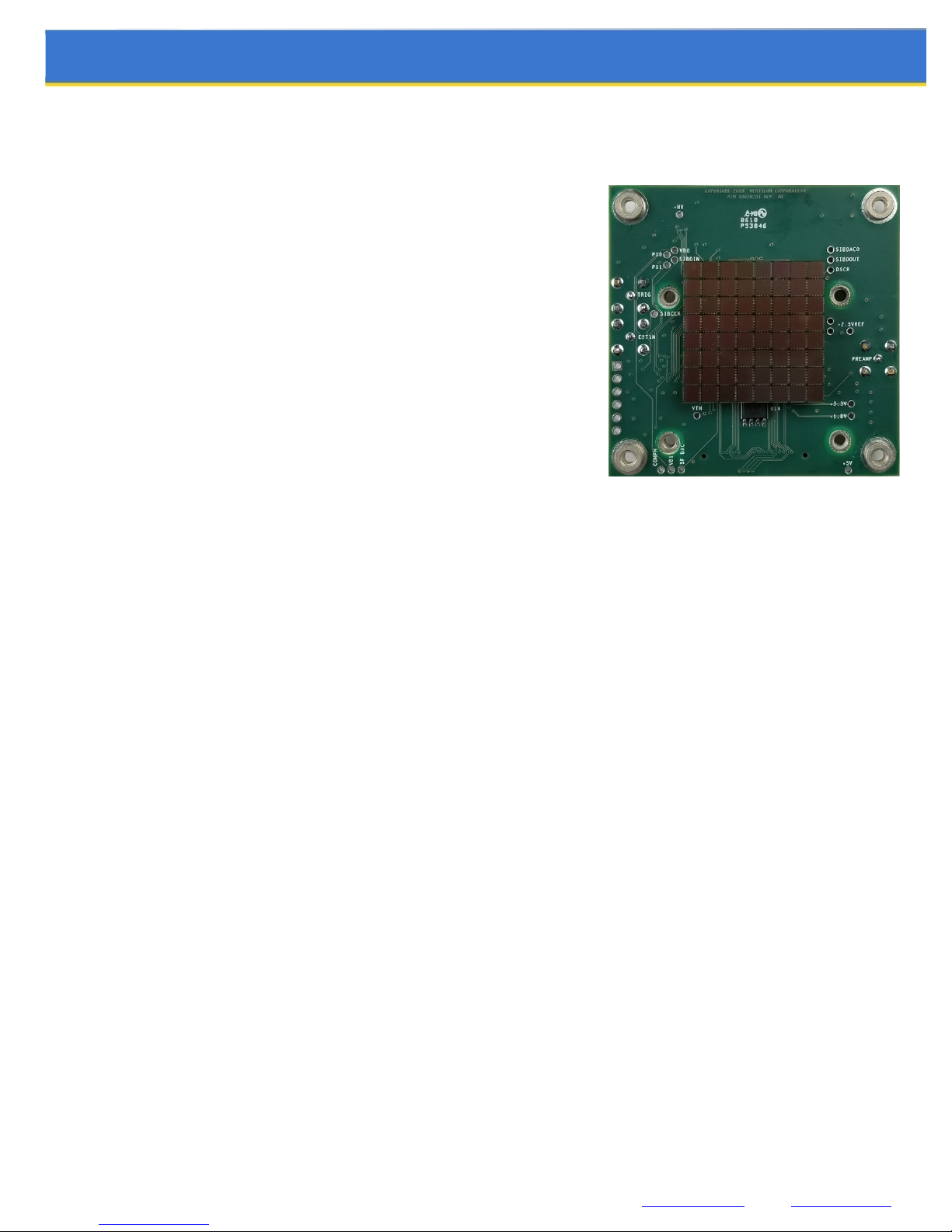
Interface board for Ketek PA3325-WB-0808 8 x 8 SIPM array
Supports 64 parallel charge output channels from SIPM array
Leading edge discriminator for event trigger and timing
Adjustable gain and threshold for discriminator channel
High voltage circuitry to bias the SiPM array
Integrated temperature sensor
100% compatible with Vertilon’s PhotoniQ multichannel DAQs
Simplified control through PhotoniQ graphical user interface
User Guide
The SIB864 sensor interface board allows the Ketek PA3325-WB-0808 8 x 8 silicon photomultiplier (SIPM) array to easily
interface to a Vertilon PhotoniQ multichannel data acquisition system. The SIPM device is inserted into the bottom side of
the printed circuit board where the 64 cathode output signals are routed directly to the sensor interface board (SIB)
connectors. The SIB connectors conform to Vertilon’s standard, low-noise, multi-channel, cable interconnection system.
The connectors mate to a micro-coaxial cable assembly that passes the 64 device outputs to the PhotoniQ. Bias to SIPM
array is provided on a high voltage cable by the PhotoniQ where it can be enabled and configured through the PhotoniQ
graphical user interface. A special current-sense output from the bias interface circuitry is routed to the input of a variable
gain preamplifier on the SIB864 to represent the total AC current signal to all 64 SIPM channels. This signal, which is
available to the user on an SMB jack, is fed into a user-programmable threshold leading edge discriminator. The
discriminator generates a trigger signal on an SMB jack when an event exceeding a predefined energy threshold is
detected on the PA3325-WB-0808 device. The trigger output is typically connected to the trigger input of the PhotoniQ
data acquisition system where it is used to initiate the collection of the energy signals from the SIPM array connected to
the DAQ system’s inputs. Alternatively, it can be connected to external digital timing hardware such as a coincidence
detector. A temperature sensor located on the SIB864 provides a continuous readout of the ambient temperature near
the PA3325-WB-0808. The full functionality and operation of the SIB864 is conveniently controlled through the
PhotoniQ’s graphical user interface. Intelligent software in the PhotoniQ constantly monitors the status of its SIB
connectors to determine the type of sensor interface board attached to them. Once recognized, a dialog box specific to
the recognized SIB is made available in the GUI through which the user has complete control over its operation.
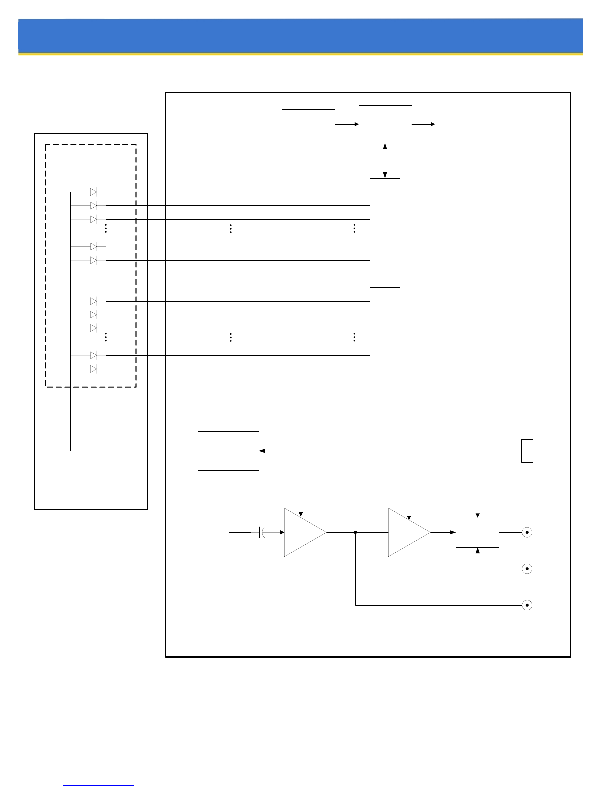
The various functions on the SIB864 are described in greater detail on the following pages. When necessary, refer to the
functional block diagram shown in Figure 1 below.
Vertilon Corporation, 66 Tadmuck Road, Westford, MA 01886 / Tel: (978) 692-7070 [email protected] www.vertilon.com
- 7 -
Page 8
User Guide
SiPM
CATHODE
OUTPUTS
TEMPERATURE
SENSOR
A1 P1
A2
A3
D7
D8
E1
E2
E3
H7
H8
P2
P3
P31
P32
P33
P34
P35
P63
P64
CONTROLLER
CONTROL/
STATUS
J1
SIB CONNECTOR
J2
SIB CONNECTOR
SYSTEM
CONTROL
SiPM
ANODES
KETEK
PA3325-WB-0808
8 X 8 SiPM ARRAY
HIGH
VOLTAGE
INTERFACE
CURRENT
GAIN
AMP
VERTILON SIB864
PA3325-WB-0808
SENSOR INTERFACE BOARD
Figure 1: Functional Block Diagram
THRESHOLD
COMP
CONFIG
TRIGGER
LOGIC
HV
POWER
TRIG
EXT IN
PREAMP
OUT
J7
J4
J5
J6
Vertilon Corporation, 66 Tadmuck Road, Westford, MA 01886 / Tel: (978) 692-7070 [email protected] www.vertilon.com
- 8 -
Page 9

Specifications
(TA = +25C, unless otherwise noted)
Description Sym Min Typ Max Units Notes
INPUT CHANNELS
User Guide
Quantity 64
Cathode Bias Voltage VB +0.25 V
Cathode Pulldown Resistance R N/A
PREAMPLIFIER
Transimpedance (Low Gain) R
Transimpedance (Med Gain) R
Transimpedance (High Gain) R
in
in
in
187
374
750
Nominal Baseline Voltage +2.50 V
Signal Range +0.50 +2.50 V
LEADING EDGE DISCRIMINATOR
Threshold Adjustment Range V
Threshold to Output Delay t
TRIGGER OUTPUT
d
1.5 2.5 V
th
10 nsec
Output Impedance 50
64 direct coupled channels to PhotoniQ channels 1 to 64.
Detector cathode voltage supplied from PhotoniQ data
acquisition system
The cathodes do not have on-board pulldown resistors.
Gain selected through GUI interface.
Maximum signal amplitude is 2.0V below baseline. Note:
these levels are halved when the preamplifier SMB output is
terminated into 50 ohms.
Nominal baseline level at discriminator input is 2.5V.
Threshold (0 to 50%) controlled through GUI interface.
Tested with a 375 mV rectangular pulse measured at the
preamplifier output. Discriminator threshold set at 10%.
Logic High Output Level V
Logic Low Output Level V
DIMENSIONS
Width W 57.4 mm
Length L 57.4 mm
Thickness T 1.57 mm
Vertilon Corporation, 66 Tadmuck Road, Westford, MA 01886 / Tel: (978) 692-7070 [email protected] www.vertilon.com
+4.3 +4.8 V
OH
OL
+0.2 +0.6 V
Table 1: Specifications
- 9 -
(IOH = -32mA)
(IOL = 32mA)
(printed circuit board only)
Page 10
User Guide
Typical Radiation Detection Setup
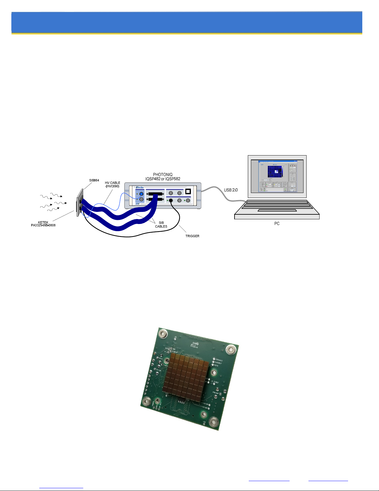
A typical radiation detection setup using a SIB864 is shown below. The Ketek PA3325-WB-0808 silicon photomultiplier
array is connected to the SIB864 which is positioned in an optical assembly to detect incoming radiation. The 64 outputs
from the SIPM array are routed on the SIB864 to the SIB connectors that connect to a PhotoniQ IQSP482 or IQSP582
multichannel data acquisition system. The discriminator channel on the SIB864 produces a trigger to the PhotoniQ
whenever a radiation event is detected on any of the SIPMs in the array. The energy level threshold for the radiation
event is set by the user through the PhotoniQ graphical user interface. Charge signals from the 64 cathodes of the
PA3325-WB-0808 device are acquired by the PhotoniQ for each trigger produced by the SIB864. Digitized output data
from the PhotoniQ is sent through a USB 2.0 connection to a PC for display, logging, or real time processing. In the figure
below, the PhotoniQ GUI is set to display an 8 x 8 image of the energy levels for each event captured.
Figure 2: Typical Radiation Detection Setup
PA3325-WB-0808 Detector Mounting
The SIB864 supports the Ketek PA3325-WB-0808 8 x 8 silicon photomultiplier array. This particular model of the device
is mounted to the bottom of the sensor interface board through two high density connectors. The SIPM device attached to
a SIB864 is shown below.
Figure 3: PA3325-WB-0808 Detector Mounting
Vertilon Corporation, 66 Tadmuck Road, Westford, MA 01886 / Tel: (978) 692-7070 [email protected] www.vertilon.com
- 10 -
Page 11
User Guide
Detector Channels
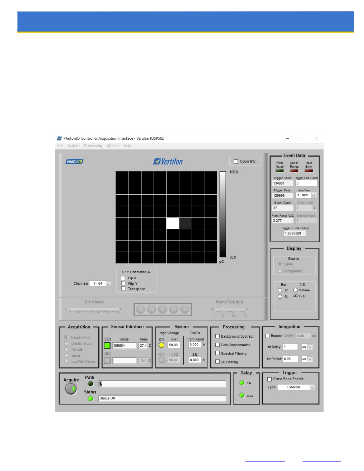
The 64 cathode signals from the PA3325-WB-0808 device are routed directly on the SIB864 to the SIB connector. These
signals connect to channels 1 through 64 of a Vertilon PhotoniQ IQSP482 or IQSP582 charge integrating data acquisition
system. The PhotoniQ utilizes DC-coupled high speed transimpedance amplifiers that maintain a DC bias voltage of
+0.250 volts on each of its inputs. Because the PA3325-WB-0808 is configured on the SIB864 as a common anode type,
the current polarity to the PhotoniQ preamplifiers is out of the inputs. For this reason, the Input Polarity under the Data
Configuration menu in the PhotoniQ GUI should be set to positive. See the PhotoniQ user’s manual for more details. The
figure below shows a typical SIB864 display of random particle signals on the 8 x 8 SIPM array.
Figure 4: PhotoniQ IQSP582 Graphical User Interface
Vertilon Corporation, 66 Tadmuck Road, Westford, MA 01886 / Tel: (978) 692-7070 [email protected] www.vertilon.com
- 11 -
Page 12
User Guide
Detector Channel Mapping
The 64 SIPM channels from the PA3325-WB-0808 are labeled in Ketek’s datasheet as channels A1 through H8. These
channels map to Vertilon’s PhotoniQ data acquisition system channels according to the table below.
Ketek SIPM Array Channel Number Vertilon DAQ Channel Number
A1, A2, …, A8 1, 2, …, 8
B1, B2, …, B8 9, 10, …, 16
C1, C2, …, C8 17, 18, …, 24
D1, D2, …, D8 25, 26, …, 32
E1, E2, …, E8 33, 34, …, 40
F1, F2, …, F8 41, 42, …, 48
G1, G2, …, G8 49, 50, …, 56
H1, H2, …, H8 57, 58, …, 64
Table 2: SIPM Array Channel Mapping
High Voltage Interface
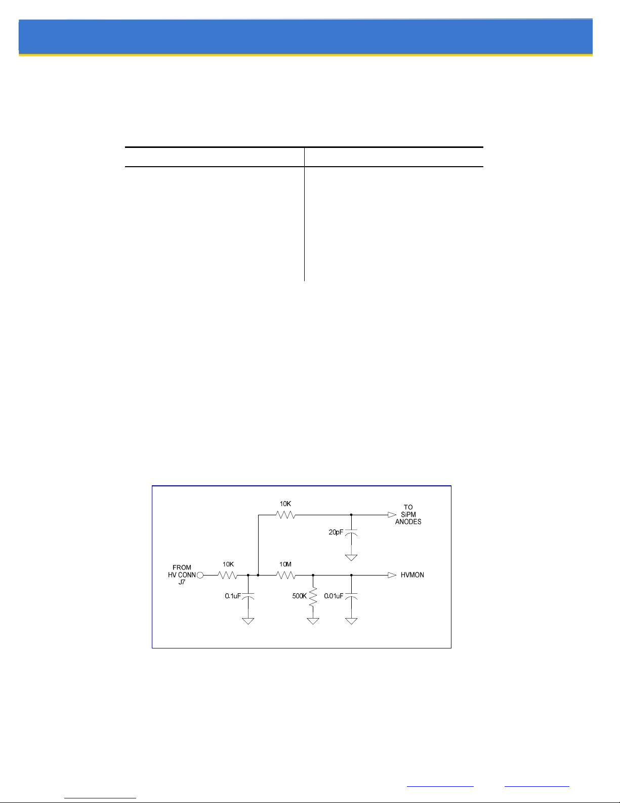
The SIB864 employs the interface circuit shown below between the high voltage input connector, J7, and the common
anodes of the SiPM array. The monitor output (HVMON) allows the high voltage anode bias to the SIPMs to be indirectly
monitored at a reduced voltage level. Voltage readings at the monitor point should be scaled by a factor of 21. Calibration
of the scale factor may be required for very accurate measurements.
Warning: The high voltage section of the SIB864 contains signals at voltage levels
that can exceed negative 100 volts. Never touch a component or signal in this area.
Figure 5: SIPM High Voltage Interface Circuit
Vertilon Corporation, 66 Tadmuck Road, Westford, MA 01886 / Tel: (978) 692-7070 [email protected] www.vertilon.com
- 12 -
Page 13
User Guide
Preamplifier
The anodes from each SIPM device in the array are bussed together and connected to the input of a single currentsensitive preamplifier on the SIB864. The preamplifier generates a voltage signal in response to the current signal on its
input from any of the 64 SIPMs in the array. This voltage signal is available on an SMB output connector on the SIB864
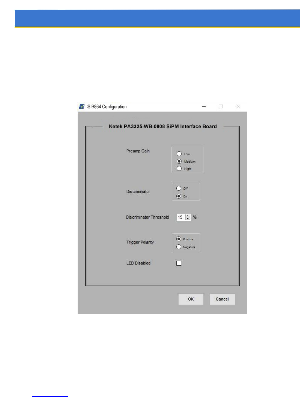
and is also fed to the input of the discriminator. There are three settings for the preamplifier gain — low, medium, and
high — which are selected through the SIB864 configuration dialog box in the PhotoniQ graphical user interface shown
below.
Vertilon Corporation, 66 Tadmuck Road, Westford, MA 01886 / Tel: (978) 692-7070 [email protected] www.vertilon.com
Figure 6: SIB864 Dialog Box
- 13 -
Page 14

User Guide
Discriminator
The discriminator generates a logic signal when a pulse from the preamplifier exceeds a user-defined threshold. The
SIB864 GUI dialog box allows the user to set this threshold between 0 and 50% where 50% is equal to one half of the
maximum possible signal amplitude in the discriminator channel. When a pulse is detected, the trigger output from the
board becomes active. The polarity can be set to either positive or negative.
Figure 7 shows the operation of the leading edge discriminator. A positive-going current pulse into the preamplifier results
in a negative-going pulse on its output. This pulse is compared to a threshold that is adjusted using the SIB864
configuration dialog box in the PhotoniQ GUI. A logic high (for positive polarity control) is generated after a small delay
(td) from when the pulse first crosses the threshold, Vth. The discriminator switches back to a logic low when the pulse
crosses the threshold from the opposite direction as it returns back to the baseline level.
INPUT
CURRENT
V
PREAMP
OUTPUT
THRESHOLD
POINT
DISCRIMINATOR
OUTPUT
th
TRIGGER
t
d
POINT
Figure 7: Leading Edge Discriminator Timing
An additional feature of the discriminator is a status LED that can be selectively enabled and disabled in the SIB864 GUI
dialog box. Under normal triggering conditions, this LED blinks green when and event is detected, and is off when no
event is detected. The LED blinks red if the user sets the discriminator threshold to a value below the discriminator
channel’s baseline level.
Temperature Sensor
An on-board temperature sensor is located on the bottom side of the SIB864 near the SiPM array. The sensor reports the
temperature of the circuit board in degrees Celsius to the PhotoniQ graphical user interface. This information is useful for
determining the proper bias to the SiPM array. Temperature data is not logged to a file by the PhotoniQ data acquisition
system.
Vertilon Corporation, 66 Tadmuck Road, Westford, MA 01886 / Tel: (978) 692-7070 [email protected] www.vertilon.com
- 14 -
Page 15
Top / Bottom Views
User Guide
5
2
6
8 10 1
7 11
3
4 12
9
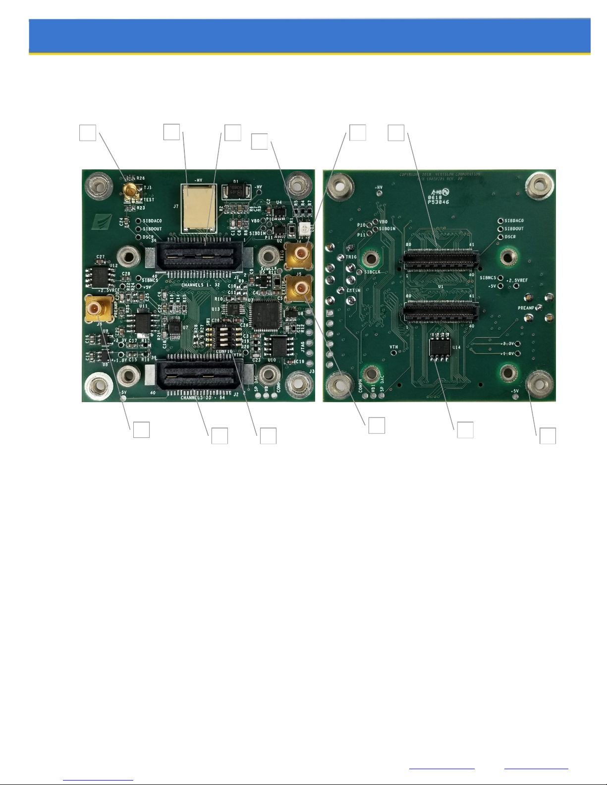
Figure 8: PCB Top and Bottom Views
1. PA3325-WB-0808 Sockets 7. Preamplifier Output (J6)
2. SIB Connector, Channels 1 to 32 (J1) 8. Trigger Output (J4)
3. SIB Connector, Channels 33 to 64 (J2) 9. External Input (Unused) (J5)
4. Configuration Switches 10. Test Input Jack (Factory Use Only)
5. SIPM Negative Bias Input (J7) 11. Temperature Sensor
6. Trigger Status LED 12. Mounting Nuts
Vertilon Corporation, 66 Tadmuck Road, Westford, MA 01886 / Tel: (978) 692-7070 [email protected] www.vertilon.com
- 15 -
Page 16
Component Locations and Functions
4.20
User Guide
57.40
57.40
4.20
J6
P15
P14
P19
TJ1
P6
P17
P8
P4
J7
39
40
39
J1
SW1
2 3 4
1
ON
P18
1
P2
P1P3
P10
P5
1
2
P11
P7
J4
J5
J3
Figure 9: Top Component Locations and Functions
Vertilon Corporation, 66 Tadmuck Road, Westford, MA 01886 / Tel: (978) 692-7070 [email protected] www.vertilon.com
P13
40
J2
2
P9
P20
P16
- 16 -
Page 17
User Guide
A1
A2
A3
A4
A5
A6
A7
A8
B1
B2
B3
B4
B5
B6
B7
B8
C1
C2
C3
C4
C5
C6
C7
C8
D1
D2
D3
D4
D5
D6
D7
D8
E1
E2
E3
E4
E5
E6
E7
E8
F1
F2
F3
F4
F5
F6
F7
F8
G1
G2
G3
G4
G5
G6
G7
G8
H1
H2
H3
H4
H5
H6
H7
H8
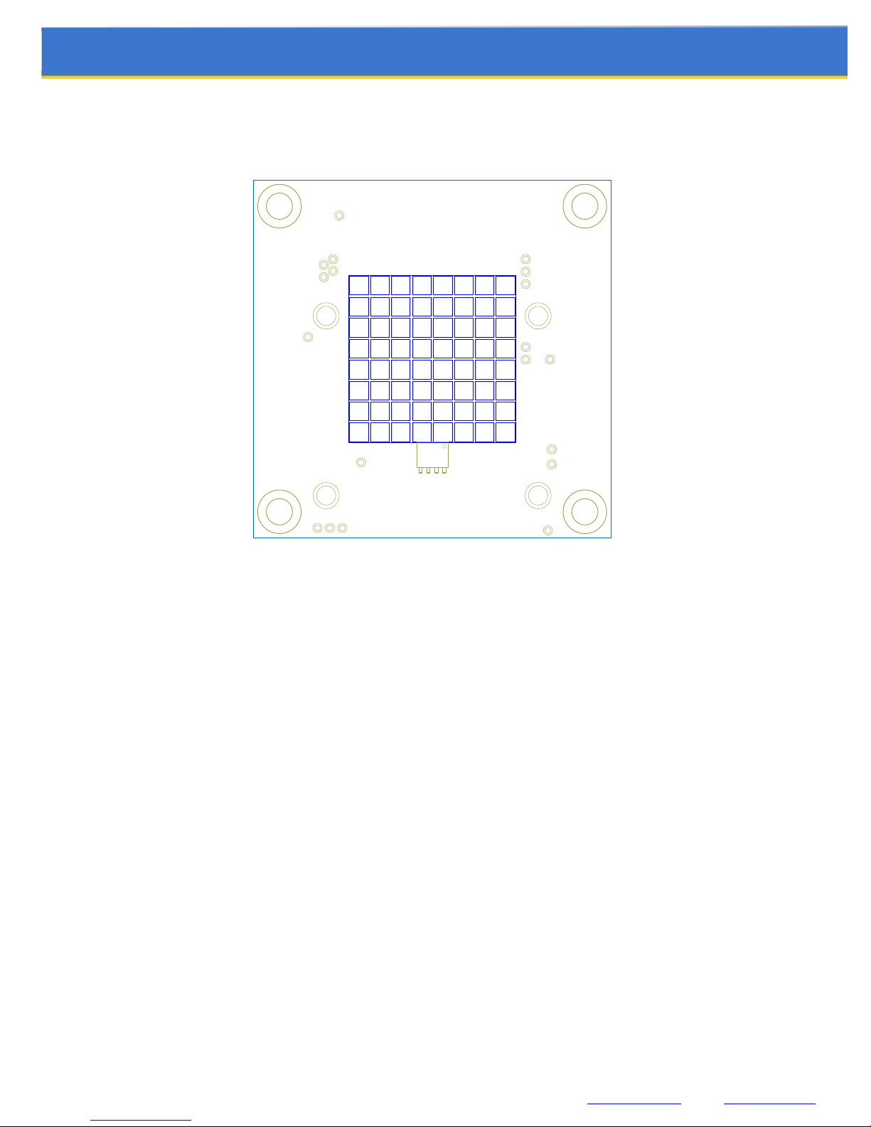
Figure 10: Bottom Component Locations and Functions
Vertilon Corporation, 66 Tadmuck Road, Westford, MA 01886 / Tel: (978) 692-7070 [email protected] www.vertilon.com
- 17 -
Page 18

Name Function Description
J1 CHANNELS 1 - 32 Sensor interface board connector, PhotoniQ channels 1 through 32.
J2 CHANNELS 33 - 64 Sensor interface board connector, PhotoniQ channels 33 through 54.
J3 JTAG JTAG interface (for factory use only)
J4 TRIG OUT Trigger output
J5 EXT IN External Input (unused, reserved for expansion)
J6 PREAMP Preamplifier output
J7 -HV External high voltage power input for bias to the SIPM array
TJ1 TEST Test input (for factory use only)
Table 3: Connectors
Name Function Description
LD1 STATUS Bicolor (red/green) LED indicator for SIB864 status.
SW1: 1-2 DEV ADDR 1:0 Sets the device address for control by the PhotoniQ. Set both switches to “ON”.
SW1: 3-4 DEV TYPE 1:0 Sets the device type for control by the PhotoniQ. Set both switches to “ON”.
Table 4: LEDs and Switches
User Guide
Name Ref # Description
+5.0V P4 +5.0V power supply from the PhotoniQ
+5.0V P13 +5.0V power supply from the PhotoniQ
+3.3V P15 +3.3V internal power supply
+1.8V P14 +1.8V internal power supply
+2.5VREF P19 +2.5V reference voltage
VB P1 Bias voltage from PhotoniQ to SIPM anodes. Normally at +0.250V when PhotoniQ set to positive input polarity.
-HV P2 SIPM array common anode voltage.
Table 5: Test Points
Vertilon Corporation, 66 Tadmuck Road, Westford, MA 01886 / Tel: (978) 692-7070 [email protected] www.vertilon.com
- 18 -
Page 19

User Guide
SIB Connector Pinout
The SIB864 connectors and cables are fully compatible with all Vertilon PhotoniQ systems. For applications utilizing data
acquisition systems other than Vertilon’s PhotoniQ series, the pinouts for connectors J1 and J2 are provided in Table 6 as
a reference.
J1 J2
Signal
Name
VB 1 HVMON0 2 VB 1 HVMON1 2
SIB_DIN0 3 SIB_CLK0 4 SIB_DIN1 3 SIB_CLK1 4
P16 5 P32 6 P48 5 P64 6
P15 7 P31 8 P47 7 P63 8
P14 9 P30 10 P46 9 P62 10
P13 11 P29 12 P45 11 P61 12
P12 13 P28 14 P44 13 P60 14
P11 15 P27 16 P43 15 P59 16
P10 17 P26 18 P42 17 P58 18
P9 19 P25 20 P41 19 P57 20
P8 21 P24 22 P40 21 P56 22
P7 23 P23 24 P39 23 P55 24
P6 25 P22 26 P38 25 P54 26
P5 27 P21 28 P37 27 P53 28
P4 29 P20 30 P36 29 P52 30
Pin
#
Signal
Name
Pin
#
Signal
Name
Pin
#
Signal
Name
Pin
#
P3 31 P19 32 P35 31 P51 32
P2 33 P18 34 P34 33 P50 34
P1 35 P17 36 P33 35 P49 36
SIB_DOUT0 37 SIB_NCS0 38 SIB_DOUT1 37 SIB_NCS1 38
SIBDAC0 39 +5V 40 SIBDAC1 39 +5V 40
Table 6: Sensor Interface Board (SIB) Connectors
Vertilon Corporation, 66 Tadmuck Road, Westford, MA 01886 / Tel: (978) 692-7070 [email protected] www.vertilon.com
Power (+5V) supplied through pin 40 if PhotoniQ is not used
Pins 3, 4, 37, 38 used by PhotoniQ and should be left unconnected
Ground supplied through SIB cable shielding
- 19 -
Page 20
Mechanical Information
4.20
User Guide
57.40
4.20
57.40
39
40
39
40
1
2
2 3 4
ON
1
1
2
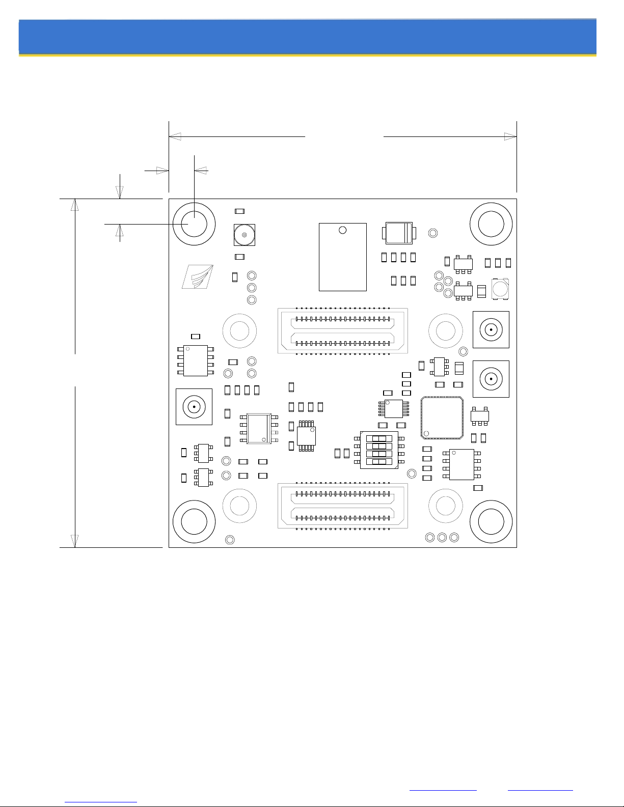
PEM mounting nut, #4-40,
bottom side mount, 4pl.
ALL DIMENSIONS IN MILLIMETER
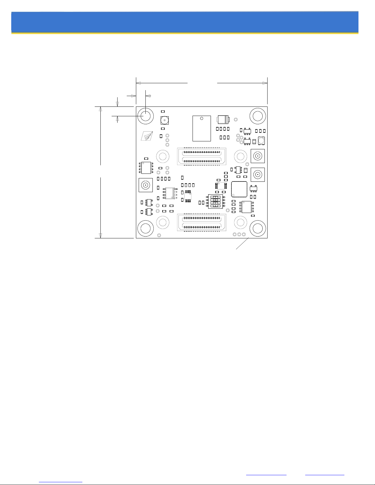
Figure 11: SIB864 Printed Circuit Board Dimensions
Vertilon Corporation, 66 Tadmuck Road, Westford, MA 01886 / Tel: (978) 692-7070 [email protected] www.vertilon.com
- 20 -
Page 21

User Guide
y for errors or for any incidental,
r alteration of data, delays, lost profits or savings, arising from the use of this document or the
ingements of patents or other rights
Vertilon Corporation has made every attempt to ensure that the information in this document is accurate and complete. Vertilon assumes no liabilit
consequential, indirect, or special damages including, without limitation, loss of use, loss o
product which it accompanies. Vertilon reserves the right to change this product without prior notice. No responsibility is assumed by Vertilon for any infr
of third parties which may result from its use. No license is granted by implication or otherwise under the patent and proprietary information rights of Vertilon Corporation.
© 2018 Vertilon Corporation, ALL RIGHTS RESERVED
UG2871.1.1 Feb 2018
Vertilon Corporation, 66 Tadmuck Road, Westford, MA 01886 / Tel: (978) 692-7070 [email protected] www.vertilon.com
- 21 -
 Loading...