

Vertigo Sound VSC-3 Operation Manual
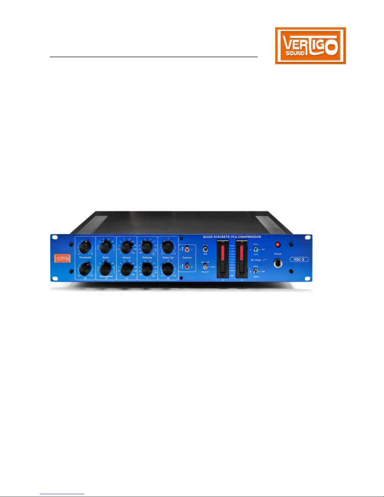
The Vertigo Sound VSC-3
Quad Discrete VCA Compressor
Operation Manual
Thank you for purchasing a Vertigo Sound Product.
The VSC-3 is the legal successor of the VSC-2, which now is a modern classic and can be
found in many top class studios around the world.
Vertigo Sound spent a lot of effort making a good product even better. The VSC-3 can do
all the tricks the VSC-2 is known and loved for plus a bunch of new features and options.
The VSC-3 is still named Q D C because it’s topology stays the same.
It is so named, because it uses 4 VCAs built using only discrete components.
It’s design is a nod toward the best VCA based compressors of the 70s and 80s.
The Vertigo VCA is in fact named 1979. Some of the best features of these classic Compressors
have been complimented in the VSC.
This classic based topology is combined with a modern mastering grade signal path.
Some unique and innovative features lie beneath the bonnet, such as the ratio which increases
with level in S mode.
The basic idea and concept of the VSC-3
The Vertigo Sound Limiter incorporates four discrete 1979 VCAs for two channels. Each channel
has one VCA in the Audio Path and another one inside the sidechain. In stereo mode both
sidechains are active (they are not summed together) and the higher signal peak on any of both
channels results in the compression of both (in Stereo SC Mode).
Therefore the VSC-3 is reacting also on out of phase signals without image shift.
Moreover, the detector (a Peak Forward Design) of each channel works in such a way, that stereo
compression can be achieved even without stereolinking. This precision makes the VSC-3 also
the first choice for mastering applications. Although the VSC-3 was developed as a
B C. Each channel provides all controls separately which makes it also a Must Have
for processing while recording.

2
Installation and Hook Up
The VSC-3 generates very little heat so it is not necessary to leave an empty space
for ventilation above or below the unit. But: Discrete Vcas are sensitive for all
heating influences (especially differences in temperature). Don’t put heat generating
devices below and above inside your rack.
The unit can be used with either balanced or unbalanced sources and the outputs
can be loaded either balanced or unbalanced:
output
The audio output is of the type electronically floating
balanced with B B® or 1646 IC-Type.
The output load should not be less then 600 Ohms.
If one of the output pin 2 or 3 is grounded, the signal
level on the other pin raises by + 6 dB.
Max Output Level is + 27 dbu at 600 Ohms.
input
The audio input is totally isolated by a C input
line transformer. The primary winding of the transformer is wired to Pin 2 and Pin 3.
Max. Input Level is + 22 dbu.
Balanced IN /OUT
Pin 1 = Ground / Shiel d
Pin 2 = Audio + ( hot )
Pin 3 = Audio – ( cold )
unBalanced IN /OUT
Pin 1 = Ground / Shiel d
Pin 2 = Audio + ( hot )
Pin 3 = Audio Common / G round / S hield
The Threshold
Sets the level above which signals will be compressed or limited. Rotating
the control clockwise raises the threshold. The Threshold is adjustable from
– 22 to + 23 dBu. We incorporated a Zoom In b etween – 6 dBu and + 10 dBu
to give you a more sensitive control and resolution between this commonly
used Level Area.
Start with threshold fully clockwise. Then turn the control slowly anticlockwise until the right
amount of compression is processed. Re-adjust setting if other parameters are changed.

3
The Ratio
Sets the compression slope, which determines how the output signal
will change in relation to the input signal once the input signal exceeds
the threshold. The higher the ratio, the greater the compression, and
the more squeezed the sound.
Examples
With a setting of 2 : 1, a 2 dB input change for signals above
the threshold results in a 1 dB output change.
Use the S TT M for all
applications where a harsh start of gain
reduction or audible compression is
unwanted. Please feel free to experiment !
Try e.g, on Snare !!!
This characteristic comes close to the
sound of some classic Opto-and variable
MU Compressors.
Use both compressor channels for 1 Signal!
Connect Output A to Input B and use it for
processing a mono signal (e.g. vocals)-put
channel A in Soft Mode and channel B to 8:1Use channel B controls (Attack and Theshold)
to create your own compression curves.
soft
This is not the commonly known
soft knee characteristic !
Soft is better described with Tip Toe — a Ratio
which increases with level — a Threshold related
Ratio from 1 : 1 up to 8 : 1.
The compressor tiptoes into compression with
very low ratios getting higher, analogue
to the signal, providing an inaudible start of
compression.
Medium to Hard Knee
Characteristics
Hard knee or soft knee response: each type of
response gives a different limiting action.
The hard knee response is generally considered
more severe but punchy and the soft knee
response more musical but limp.
2 : 1 / 4 : 1 / 8 : 1 / 10 : 1/ Brick (40 : 1) = compressing
from medium to hard knee
Brick = Limit
Ratio selection switch compensates to provide
equal loudness, allowing immediate comparison.
N N

4
The attack
The parameter A of the peak detector sets how fast the limiter’s internal
circuitry reacts to changes in input level. The longer the attack time, the
more of a signal’s dynamics are let through before the limiting action kicks in.
With slower attack times, the limiter responds more to average signal level.
This produces a smoother sound that tends to retain dynamic character, but
the trade-off is that the VSC-3 cannot react as rapidly to sudden level shifts.
There’s a right setting for all situations:
0,1 ms · 0,3 ms · 1,0 ms · 3,0 ms · 5,0 ms · 10,0 ms · 15,0 ms · 20,0 ms · 30,0 ms · 40,0 ms
Start from 10 ms setting. Shorter Attacks may be musical in soft mode. Just find your sound !
Put a big amount of compression (10 db gain reduction) onto your mix and search for the best
musical and rhythm action of your compressor when changing the Attack setting !
Reduce the amount of gain reduction to a sensible amount (2–4 dB) with the threshold knob.
Try this strategy with the release time and maybe jump back to this procedure (attack) again.
This approach is close to using an EQ, where unwanted signals are spotted with a high boost
when switching and sweeping through the frequency band.
Setting a longer attack time with a
bass guitar allows more of the picking
attack to come through.
The Attack times can be set fast enough
to use the VSC-3 as an overload protector
but in common musical use slower
attacks like 3 ms or higher leave transients
unprocessed and offer a quite musical
squeezing.
N
Examples
k
 Loading...