

Vertex Water Products PWC-9500 Owners & Installation Manual

PureWaterCooler
PureChill Water Dispenser
OWNERS INSTALLATION
OWNERS INSTALLATION
OWNERS INSTALLATION OWNERS INSTALLATION
MANUAL
MANUAL
MANUALMANUAL
PWC-9500

Table of Contents
Page
1.0 Introduction 1
2.0 Receiving 1
3.0 Product Description 2
4.0 Installation 5
5.0 Operation 9
6.0 Filter Monitor 11
7.0 Filter Replacement 12
8.0 Leak Detection 13
9.0 Trouble Shooting Guide 15
9.0 Specifications 16
10 Warranty 17
List of Figures
Fig. 1 Flow Schematic 2
Fig. 2 PWC-9500 Assembly 3
Fig. 3 Back View of Cooler 4
Fig. 4a-b Installation Precaution 5-6
Fig. 5 Saddle Valve 7
Fig. 6 Quick Connect Fittings 8
Fig. 7 Hot/Cold Power switches 9
Fig. 8 Control Panel 10
Fig. 9 Tank Drain 11
Fig. 10 Leak Detection 13
Fig. 11 Leak Detection probes 14

1.0 Introduction
The Vertex PureWaterCooler™ products are a means to produce
good-tasting, safe water without using bottles of stored water. The PureChill
model PWC-9500 described here is made for floor-standing use.
Please read all the instructions in this manual before operating the PureWater-
Cooler™.
2.0 Receiving the Cooler
2.1 Unpacking
The PureChill™ model PWC-9500 is shipped completely assembled
in 2 separate cartons. Open the top assembly box and pull the cooler out.
Save the box and packing materials for use in the event of a return. The cooler
base cabinet is shipped separately in another carton. Remove the top of the
box and pull the cabinet off of the base of the carton.
2.2 Inspection
Inspect the cooler top assembly and base cabinet for obvious shipping
damage. Look at the exterior panels to see if they are dented or damaged.
1
3.0 Description
3.1 Assembly
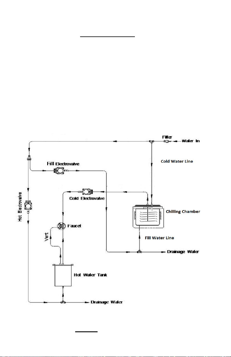
Figure 1. The cooler has one chilling chamber and one hot tank. This chilling
chamber holds one gallon of water and is automatically filled at start-up. This
water is cooled in the chilling chamber with refrigerant coils. The cold water
drinking line is comprised of a sealed stainless steel coil submerged inside this
chamber. There is a separate hot water tank with an internal heater coil which is
fed by water pressure directly from the line in. The hot water tank is directly beside the cold water tank. The compressor and expansion valve are inside the
cabinet. The controls for dispensing water are on the front panel.
The countertop portion of the PWC-9500 assembly drawing is shown in
Figure 1 Flow Schematic
2
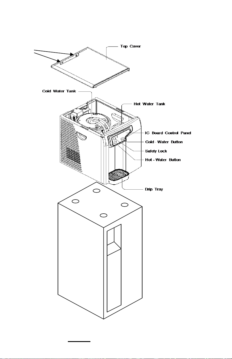
Screws
Top Assembly
Figure 2
Base cabinet Assembly
PWC-9500 Assembly
3
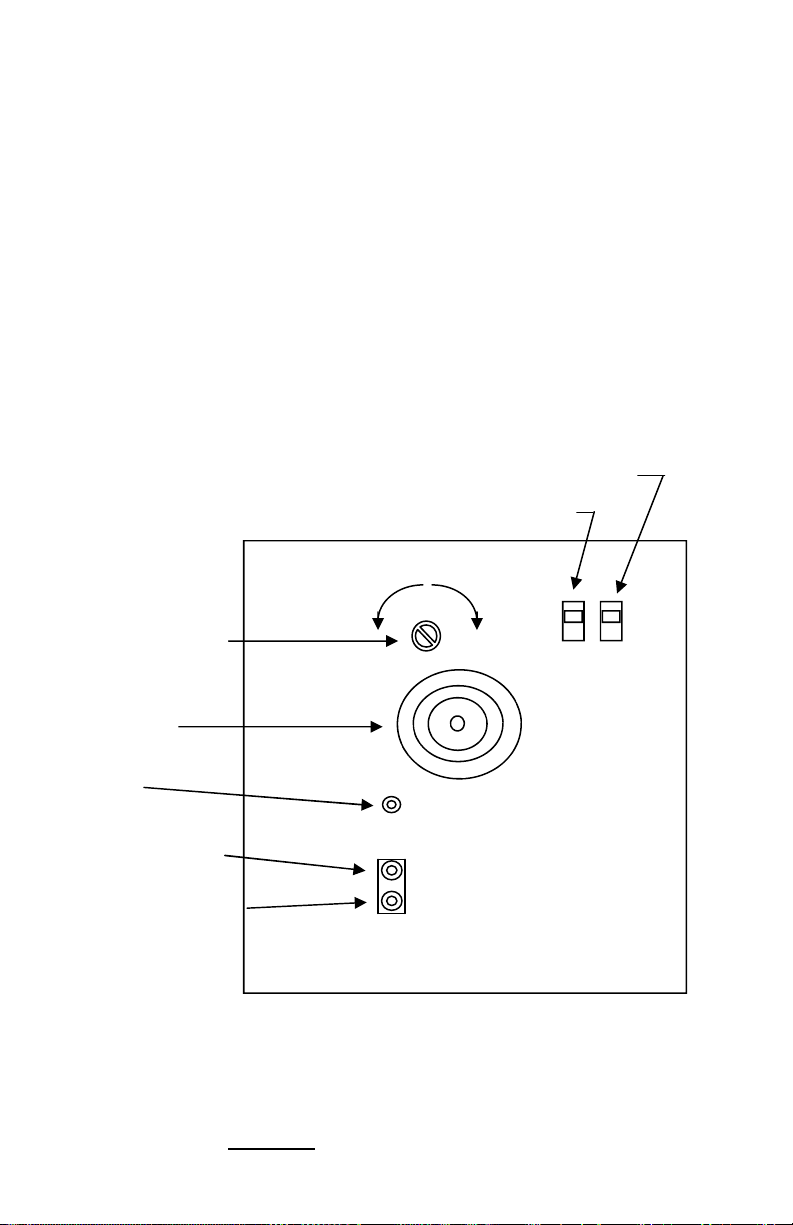
3.2 Rear View
On the back of the cooler are the main power switches; one for heating and one for cooling. When heating or cooling is occurring, indicator lights on
the front panel will turn on. The hot temperature is fixed at a nominal 180°F
and is controlled with a thermostat mounted on the outside of the hot tank. The
cold temperature can be adjusted between 36°F and 54°F by a using a screw
driver on the slot on the back. Turn to the left to increase warmth and to the
right to increase cold. DO NOT TURN PAST THE STOPS. There is a cooling
fan which exhausts to the rear, so a clearance of 6-inches from a wall is required.
Cold Water
T
emperature adjust
Hot Power Switch
C
old Power Switch
W
e
m
r
a
C
r
o
l
d
e
r
Cooling Fan
Feed Water
nlet Port
I
Drain Line (Cold Tank)
Drain Line (Hot Tank)
Figure 3 Back View of Cooler
4
4.1 Assembly of Countertop to Cabinet
Identify the four depressions on the top of the base cabinet where the
four feet of the cooler will locate. Lift the cooler and placed it on top of the cabinet, aligning the feet of the cooler to the previously located depressions.
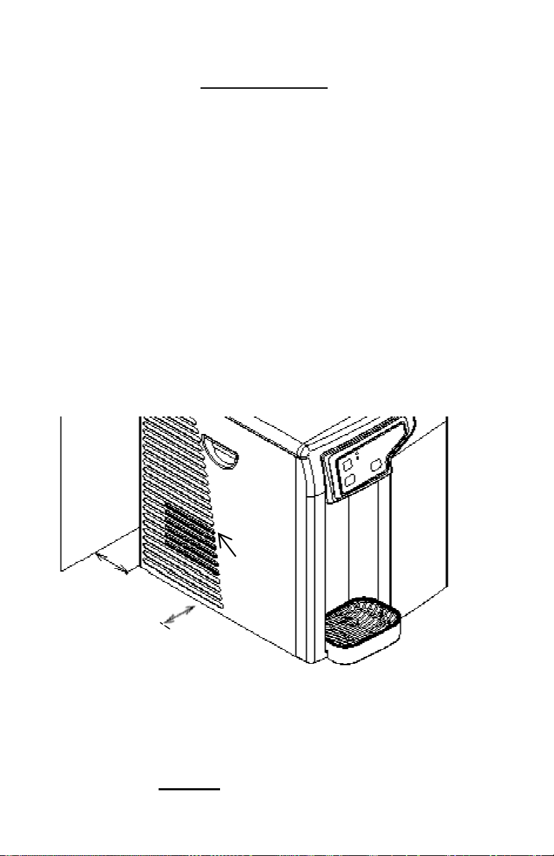
4.2 Positioning the Cooler
There are some precautions to take when positioning and using the
PureWaterCooler™. See the items in Figure 4a and 4b. In addition, the
cooler must be located near the supply water. Flexible 1/4-inch plastic tubing
may be used for the feed connection. Normally, this connection should be
within 25-feet of the cooler.
Important Note: Do not cover air intake vent as this will prevent proper chilling
from occurring.
4.0 Installation
i
n
Air Intake
Intake
Vent
vent
5
6
i
n
4
Keep at least a 6 in. distance between the cooler and the wall.
Figure 4a Installation Precautions
 Loading...