

Page 1
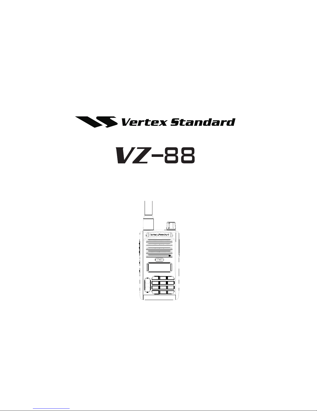
Operating Manual
Page 2

CONTENTS
Product Safety and RF Energy Exposure Booklet for
Portable Two-Way Radios
........................................... 3
RF Energy Exposure Awareness, Control
Information and Operational Instructions for
Occupational Use
.................................................... 3
Federal Communication Commission (FCC)
Regulations
............................................................. 4
RF Exposure Compliance and Control Guidelines
and Operating Instructions
...................................... 5
Approved Accessories
............................................ 6
Electromagnetic Interference/Compatibility
............. 6
Use of Communication Devices While Driving
........ 7
Operational Cautions
.............................................. 8
Intrinsically Safe Radio Information
........................ 9
Accessories Installation
............................................. 11
Ni-MH/Li-ion battery Installation
............................ 11
Detach Ni-MH/Li-ion Battery
................................. 11
Antenna Installation
.............................................. 12
Detach Antenna
.................................................... 12
Belt Clip Installation
.............................................. 13
Power Adaptor and Commonly Used Charger
...... 13
Battery and Charger
.................................................. 14
Battery Life Time
................................................... 14
Battery Charging with Radio
................................. 14
Battery Charging Only
........................................... 15
Charger LED Indicators
........................................ 15
Charging Time
....................................................... 15
Cleaning and Maintenance
....................................... 15
General Description
.................................................. 16
Familiar with VZ-88 Radio ..................................... 16
LCD Icons
............................................................. 17
Digit Keypad
.......................................................... 18
Basic Operations
................................................... 18
Power On/Off
............................................................ 18
Volume Adjustment
.................................................. 18
Frequency Display Mode (VFO)
................................ 18
Channel Save
............................................................ 18
Channel Display Mode (MR)
..................................... 19
FM Frequency Display Mode (FM VFO)
.................... 19
FM Channel Save
...................................................... 19
FM Channel Display Mode (MR)
............................... 19
Short Cut Key
............................................................ 19
Menu Selec on Mode(MENU)
............................ 19
Keypad Lock or Unlock
............................................. 19
Communica on Requirement
.................................. 19
RX and Signal Strength Indica
on
............................. 20
Calling and Monitor
.................................................. 20
Hands Free / VOX
..................................................... 20
LCD Backlit
................................................................ 20
Ini aliza on
.............................................................. 20
LED Indicator
........................................................ 21
Tones
..................................................................... 21
Short Cut Keys
.......................................................... 22
Menu Setting
............................................................. 25
Menu List
............................................................... 25
Menu Operation
.................................................... 26
Menu Functions or Settings
.................................. 26
ALIAS - Channel Alias
................................................ 26
APO - Auto Power Off
............................................... 26
Channel BANK
........................................................... 26
1
CONTENTS
Page 3

BATSAV – Ba ery Saver ............................................. 27
BCLO - Busy Channel Lock Out
.................................. 27
BEEP – Key Tone Beep
............................................... 27
BW - Band Width
...................................................... 27
DW - Dual Watch
....................................................... 27
LIGHT Op ons
........................................................... 27
LOCK Mode Se
ng
................................................... 27
OPNMSG – Opening Display Message
....................... 28
PSWD – Password Se ng
......................................... 28
ROGER Se ng
........................................................... 28
TOT (TX Time- out - mer) Se ng
............................ 28
TXSTOP Se ng
.......................................................... 28
VOX Se
ng
............................................................... 28
OFFSET – VFO frequency offset
................................. 29
STEP – VFO frequency step
....................................... 29
CPS
...........................................................................29
Channel Information setting
..................................29
VFO Information setting
........................................29
Function parameter setting
...................................30
DTMF setting
........................................................30
FM function setting
................................................30
Scan List
...............................................................30
Programmable side button
....................................30
Monitor ..................................................................... 30
Scan On/Off
............................................................... 30
Nuisance Delete
........................................................ 30
High/Low Power
........................................................ 30
Talk-around/Repeater
............................................... 31
Back Light On/Off
...................................................... 31
Clone Function
..........................................................31
The Steps of Clone Operation:
..............................31
PL/DPL Frequency/Code Table
.................................32
Standard PL (CTCSS) Frequency (Hz) Table:
.......32
Standard DPL (CDCSS) Code Table:
....................33
2
CONTENTS
Page 4
Product Safety and RF
Energy Exposure Booklet
for Portable Two-Way
Radios
The information provided in this document supersedes
the general safety information contained in user guides
published prior to February 2002.
BEFORE USING THIS RADIO, READ THIS
BOOKLET WHICH CONTAINS
IMPORTANT OPERATING INSTRUCTIONS
FOR SAFE USAGE, RF ENERGY
AWARENESS, CONTROL INFORMATION
AND OPERATIONAL INSTRUCTIONS,
FOR COMPLIANCE WITH RF ENERGY
EXPOSURE LIMITS IN APPLICABLE
NATIONAL AND INTERNATIONAL
STANDARDS. ALSO READ THE
OPERATIONAL INSTRUCTIONS FOR
SAFE USAGE. FOR RADIOS
THAT HAVE
BEEN APPROVED AS INTRINSICALLY
SAFE, READ THE INSTRUCTIONS AND
INFORMATION ON INTRISINIC SAFETY
ON PAGE 3-9 OF THIS BOOKLET.
RF Energy Exposure Awareness,
Control Information and Operational
Instructions for Occupational Use
NOTICE: This radio is intended for use in
occupational/controlled conditions where users
have full knowledge of their exposure and can
exercise control over their exposure to meet the
occupational limits in FCC and International
standards. This radio device is NOT authorized for
general population consumer use.
This two-way radio uses electromagnetic energy in the
radio frequency (RF) spectrum to provide
communications between two or more users over a
distance. It uses radio frequency (RF) energy or radio
waves to send and receive calls.
RF energy is one form of electromagnetic energy.
Other forms include, but are not limited to, sun
light and
x-rays. RF energy, however, should not be confused
with these other forms of electromagnetic energy,
which when used improperly, can cause biological
damage. Very high levels of x-rays, for example, can
damage tissues and genetic material.
Experts in science, engineering, medicine, health, and
industry work with organizations to develop standards
for safe exposure to RF energy. These standards
provide recommended levels of RF exposure for both
workers and the general public. These recommended
RF exposure levels include substantial margins of
protection.
!
Caution
3
Product Safety
Page 5

All Vertex Standard two-way radios are designed,
manufactured, and tested to ensure they meet
government- established RF exposure levels. In
addition, manufacturers also recommend specific
operating instructions to users of two-way radios.
These instructions are important because they inform
users about RF energy exposure and provide simple
procedures on how to control it.
Please refer to the following websites for more
information on what RF energy exposure is and how to
control your exposure to assure compliance with
established RF exposure limits:
http://www.fcc.gov/oet/rfsafety/rf-faqs.html
http://www.osha.gov/SLTC/radiofrequencyradiation/i
ndex.html
Federal Communication Commission
(FCC) Regulations
The FCC rules require manufacturers to comply with
the FCC RF energy exposure limits for portable
two-way radios before they can be marketed in the U.S.
When two-way radios are used as a consequence of
employment, the FCC requires users to be fully aware
of and able to control their exposure to meet
occupational requirements. Exposure awareness can
be facilitated by the use of a product label directing
users to specific user awareness information. Your
Vertex Standard two-way radio has a RF Exposure
Product Label. Also, your Vertex Standard user manual
or separate safety booklet includes information and
operating instructions required to control your RF
exposure and to satisfy compliance requirements.
Compliance with RF Exposure Standards
Your Vertex Standard two-way radio is designed and
tested to comply with a number of national and
International standards and guidelines (listed below)
for human exposure to radio frequency
electromagnetic energy. This radio complies with the
IEEE (FCC) and ICNIRP exposure limits for
occupational/controlled RF exposure
environments at operating duty factors of up to
50% talk–50% listen and is authorized by the FCC
for occupational use only.
In terms of measuring RF energy for compliance with
these exposure guidelines, your radio generates
measurable RF energy only while it is transmitting
(during talking), not when it is receiving (listening)
or in standby mode.
NOTE: The approved batteries, supplied with this radio,
are rated for a 5–5–90 duty factor (5% talk–5%
listen–90% standby) even though this radio complies
with FCC occupational exposure limits and may
operate at duty factors of up to 50% talk
Your Vertex Standard two-way radio complies with
the following RF energy exposure standards and
guidelines:
United States Federal Communications
Commission, Code of Federal Regulations; 47CFR
4
Product Safety
Page 6

part 2 sub-part J
American National Standards Institute (ANSI) /
Institute of Electrical and Electronic Engineers
(IEEE) C95.1-1992
Institute of Electrical and Electronic Engineers
(IEEE) 95.11999 Edition
International Commission on Non-Ionizing Radiation
Protection (ICNIRP) 1998
Ministry of Health (Canada) Safety Code 6. Limits of
Human Exposure to Radiofrequency
Electromagnetic Fields in the Frequency Range
from 3 kHz to 300 GHz, 1999
Australian Communications Authority Radio
communications (Electromagnetic Radiation–
Human Exposure) Standard, 2003
ANATEL ANNEX to Resolution No. 303 of July 2,
2002 "Regulation of limitation of exposure to
electrical, magnetic and electromagnetic fields in
the radio frequency range between 9 KHz and 300
GHz" and "Attachment to resolution # 303 from July
2, 2002"
RF Exposure Compliance and Control
Guidelines and Operating Instructions
To control your exposure and ensure compliance with
the occupational/controlled environment exposure
limits, always adhere to the following procedures.
Guidelines:
Do not remove the RF Exposure Label from the
device.
User awareness instructions should accompany
device when transferred to other users.
Do not use this device if the operational
requirements described herein are not met.
Operating Instructions
Transmit no more than the rated duty factor of 50%
of the time. To transmit (talk), push the Push-To-Talk
(PTT) button. To receive calls, release the PTT
button. Transmitting 50% of the time, or less, is
important because this radio generates measurable
RF energy exposure when transmitting (in terms of
measuring for standards compliance).
Hold the radio in a vertical position in
front of the face with the microphone
(and other parts of the radio including
the antenna) at least 2.5 centimeters
(one inch) away from the nose or lips.
Antenna should be kept away from the eye. Keeping
the radio at a proper distance is important since RF
exposures decrease with increasing distance from
the antenna.
When worn on the body, always place the radio in a
Vertex Standard approved clip, The use of nonVertex Standard approved accessories may result
in exposure levels, which exceed the FCC
occupational/controlled environment RF exposure
5
Product Safety
Page 7

limits.
Approved Accessories
Use only Vertex Standard approved supplied or
replacement antennas, battery chargers and batteries.
Use of Non Vertex Standard approved antennas,
battery chargers and batteries may exceed the FCC
(IEEE) and ICNIRP RF exposure guidelines.
Electromagnetic
Interference/Compatibility
NOTE: Nearly every electronic device is
susceptible to electromagnetic interference (EMI) if
inadequately shielded, designed, or otherwise
configured for electromagnetic compatibility.
Facilities
To avoid electromagnetic interference and/or
compatibility conflicts, turn off your radio in any facility
where posted notices instruct you to do so. Hospitals
or health care facilities may be using equipment that is
sensitive to external RF energy.
Aircraft
When instructed to do so, turn off your radio when on
board an aircraft. Any use of a radio must be in
accordance with applicable regulations per airline
crew instructions.
Medical Devices
Pacemakers
The Advanced Medical Technology Association
(AdvaMed) recommends that a minimum separation of
6 inches (15 centimeters) be maintained between a
handheld wireless radio and a pacemaker. These
recommendations are consistent with those of the U.S.
Food and Drug Administration.
Persons with pacemakers should:
ALWAYS keep the radio more than 6 inches (15
centimeters)from their pacemaker when the radio is
turned ON.
Not carry the radio in the breast pocket.
Use the ear opposite the pacemaker to minimize the
potential for interference.
Turn the radio OFF immediately if there is any
reason to suspect that interference is taking place.
Hearing Aids
Some digital wireless radios may interfere with some
hearing aids. In the event of such interference, you
may want to consult your hearing aid manufacturer to
discuss alternatives.
Other Medical Devices
6
Product Safety
Page 8

If you use any other personal medical device, consult
the manufacturer of your device to determine if it is
adequately shielded from RF energy. Your physician
may be able to assist you in obtaining this information.
Use of Communication Devices While
Driving
Always check the laws and regulations on the use of
radios in the areas where you drive.
Give full attention to driving and to the road.
Use hands-free operation, if available.
Pull off the road and park before making or
answering a call, if driving conditions or regulations
so require.
Operational Warnings
For Vehicle with Air Bags
Refer to vehicle manufacturer's manual
prior to installation of electronic
equipment to avoid interference with air
bag wiring.
Do not place a portable radio in the area
over an air bag or in the air bag
deployment area. Air bags inflate with
great force. If a portable radio is placed
in the air bag deployment area and the
air bag inflates, the radio may be
propelled with great force and cause
serious injury to occupants of the
vehicle.
!
WARNING
7
Product Safety
Page 9
Potentially Explosive
Atmospheres
(Explosive atmospheres refer to hazard
classified locations that may contain
hazardous gas, vapors, or dusts.)
Turn off your radio prior to entering any
area with a potentially explosive
atmosphere unless it is a portable radio
type especially qualified for use in such
areas as Intrinsically Safe (for example,
Factory Mutual, CSA, UL, or CENELEC).
Do not remove, install, or charge
batteries in such areas. Sparks in a
potentially explosive atmosphere can
cause an explosion or fire resulting in
bodily injury or even death.
The areas with potentially explosive
atmospheres referred to above include
fueling areas such as below decks on
boats, fuel or chemical transfer or
storage facilities, and areas where the
air contains chemicals or particles such
as grain, dust or metal powders. Areas
with potentially explosive atmospheres
are often, but not always, posted.
Blasting Caps and Blasting Areas
To avoid possible interference with
blasting operations, turn off your radio
when you are near electrical blasting
caps, in a blasting area, or in areas
posted: “Turn off two-way radio.” Obey
all signs and instructions.
Operational Cautions
Antennas
Do not use any portable radio that has a
damaged antenna. If a damaged antenna
comes into contact with your skin, a minor
burn can result.
Batteries
All batteries can cause property damage
and/or bodily injury, such as burns, if a
conductive material such as jewelry, keys, or
beaded chains touches exposed terminals.
The conductive material may complete an
electrical circuit (short circuit) and become
quite hot. Exercise care in handling any
charged battery, particularly when placing it
inside a pocket, purse, or other container with
metal objects.
!
Caution
!
Caution
!
WARNING
!
WARNING
8
Product Safety
Page 10
Intrinsically Safe Radio Information
The Intrinsically safe approval unit refers to a product
that has been approved as intrinsically safe by an
approval agency (for example FM Approvals, CSA, UL,
or Cenelec) and certifies that a particular product
meets the Agency's applicable intrinsic safety
standards for specific types of hazardous classified
locations. A portable radio that has been approved for
intrinsic safety will have Approval label attached to the
radio to identify the unit as being approved for
specified hazardous atmospheres. This label specifies
the hazardous Class/Division/ Group along with the
part number of the battery that must be used. The
Intrinsically Safe Approval Label will be located on the
portable radio unit.
Operational Cautions for Intrinsic Safe
Equipment
Do not operate radio communications
equipment in a hazardous atmosphere
unless it is a type especially qualified (for
example, FM, UL, CSA, or CENELEC
approved). An explosion or fire may
result.
Do not operate a radio unit that has been
approved as intrinsically safe product in a
hazardous atmosphere if it has been
physically damaged (for example,
cracked housing). An explosion or fire
may result.
Do not replace or charge batteries in a
hazardous atmosphere. Contact sparking
may occur while installing or removing
batteries and cause an explosion or fire.
Warnings for Radios Approved as Intrinsically Safe
Radios must ship from the Vertex Standard
manufacturing facility with the hazardous atmosphere
capability and the intrinsic safety approval labeling (FM,
UL, CSA, CENELEC). Radios will not be upgraded to
this capability and labeled once they have been
shipped to the field.
A modification changes the unit's hardware from its
original design configuration. Modifications can only be
made by the original product manufacturer.
Do not replace or change
accessories in a hazardous
atmosphere. Contact sparking may
occur while installing or removing
accessories and cause an explosion
or fire.
Do not replace or change
accessories in a hazardous
atmosphere. Contact sparking may
occur while installing or removing
accessories and cause an explosion
or fire.
!
Caution
!
WARNING
9
Product Safety
Page 11

Turn the radio off before removing or
installing a battery or accessory.
Do not disassemble an intrinsically
safe product in any way that exposes
the internal circuits of the unit.
Failure to use an intrinsically safe
approved battery or Approved
accessories specifically approved
for the radio unit may result in the
dangerously unsafe condition of an
unapproved radio combination being
used in a hazardous location.
Unauthorized or incorrect
modification of the intrinsically safe
approved Product will negate the
approval rating of the product.
Incorrect repair or relabeling of any
intrinsically safe Agency-approved
radio could adversely affect the
Approval rating of the unit.
Use of a radio that is not intrinsically
safe in a hazardous atmosphere
could result in serious injury or
death.
Do Not Substitute Options or Accessories
The Vertex Standard communications equipment
certified as intrinsically safe by the approving agency
(FM, UL, CSA, CENELEC), is tested as a complete
system which consists of the listed agency approved
portable, approved battery, and approved accessories
or options, or both. This approved portable and battery
combination must be strictly observed. There must be
no substitution of items, even if the substitute has been
previously approved with a different Vertex Standard
communications equipment unit
. Approved
configurations are listed by the Approving Agency (FM,
UL, CSA, CENELEC).
The Intrinsically Safe approval Label affixed to a radio
refers to the intrinsically safe classification of that radio
product, and the approved batteries that can be used
with that system.
The manual PN referenced on the Intrinsically Safe
Approval Label identifies the approved accessories
and/or options that can be used with that portable radio
unit.
Using a non Vertex Standard intrinsically safe battery
and/or accessory with the Vertex Standard a
pproved
radio unit will void the intrinsically safe approval of that
radio unit.
!
WARNING
10
Product Safety
Page 12
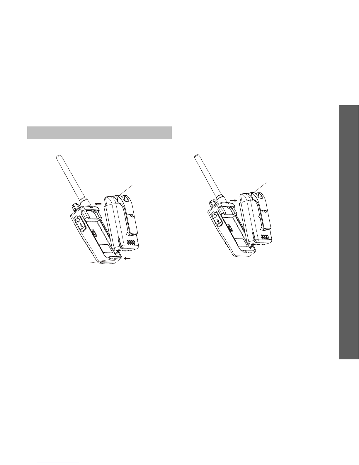
Accessories Installation
Battery Installation
a. Turn off radio
b. Turn the battery logon side up and plug the bottom
lugs into radio rail slot.
c. Press battery upper area until a “Click” sound is
heard.
Detach Battery
a. Turn off radio
b. Press down the latch until battery is removed from
radio.
c. Remove the battery from the radio.
11
Accessories Installtion
Battery
latch
Rail
slot
Battery
latch
Page 13
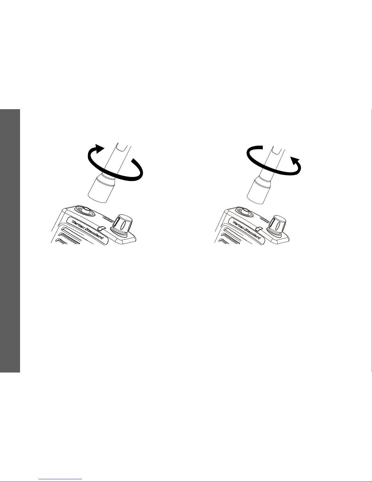
Antenna Installation
a. Screw antenna clockwise to top of radio as
indicated above.
Detach Antenna
a. Screw antenna in an anti-clockwise direction and
remove from the radio.
12
Accessories Installtion
Page 14
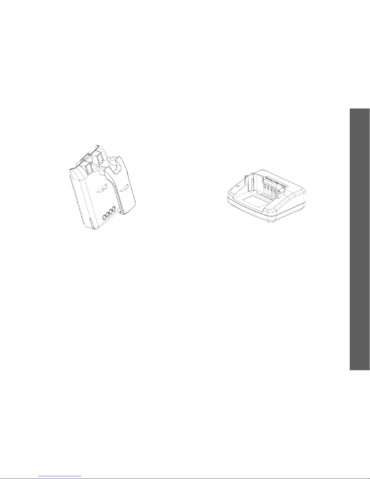
Belt Clip Installation
a. Push the belt clip in to the two holes on the back of
the battery.
b. From the front side of the battery, fix the belt clip
with 2 screws.
c. Connect the battery to the radio.
Power Adaptor and Commonly Used
Charger
a. The radio comes with a commonly used charger
and a power adaptor.
13
Accessories Installtion
Page 15
Battery and Charger
When used for the first time, for adequate power and
best performance, make sure the battery is
fully-charged before using.
To maintain best battery performance the battery
should be regularly fully discharged before recharging.
This will provide better performance than regularly
recharging the battery after only 50% of use.
The Radio battery is specially designed for the charger
and vice-versa. If a 3
rd
party charger is used the battery
may be damaged and there may be overheating of the
battery.
Battery Life Time
If the battery has been fully charged then the power
save function (default setting) can extend the battery
life to 12 hours.
Note: the calculation of battery using time is based on
5% TX /5% RX /90% standby standard duty factor.
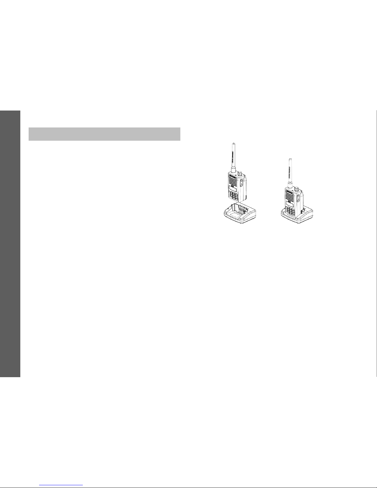
Battery Charging with Radio
a. Place the charger on a flat surface.
b. Plug the power adaptor to the charger cradle.
c. Plug adaptor to power outlet.
d. Insert radio to the slot as shown in the above
drawing.
Note: To ensure total charge of the battery, please
ensure the radio is turned off when charging the
battery.
14
Battery and Charger
Page 16
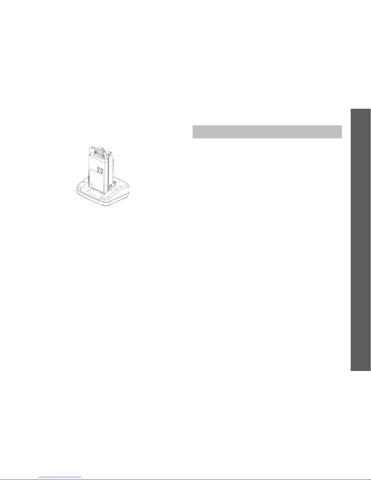
Battery Charging Only
If charging the battery alone, for step 4 above, please
align the battery to the grove and make sure the inner
side of the battery faces towards the front of the
charger as shown above. Ensure they make a good
connection.
Charger LED Indicators
LED shows red when charging, turn green when fully
charged.
Charging Time
It will take about 4 hours to charge the battery.
Cleaning and Maintenance
Use wet and soft cloth to clean the radio surface.
Do not use alcohol or cleaning fluid.
If radio is not in use, please ensure the earphone
jack cover is in place.
Do not dip the radio in to water.
If radio is dropped into water, please turn it off and
take out the battery. Use a soft cloth to wipe the
radio dry. Do not turn the radio on until it is fully
dried out.
15
Cleaning and Maintenance
Page 17
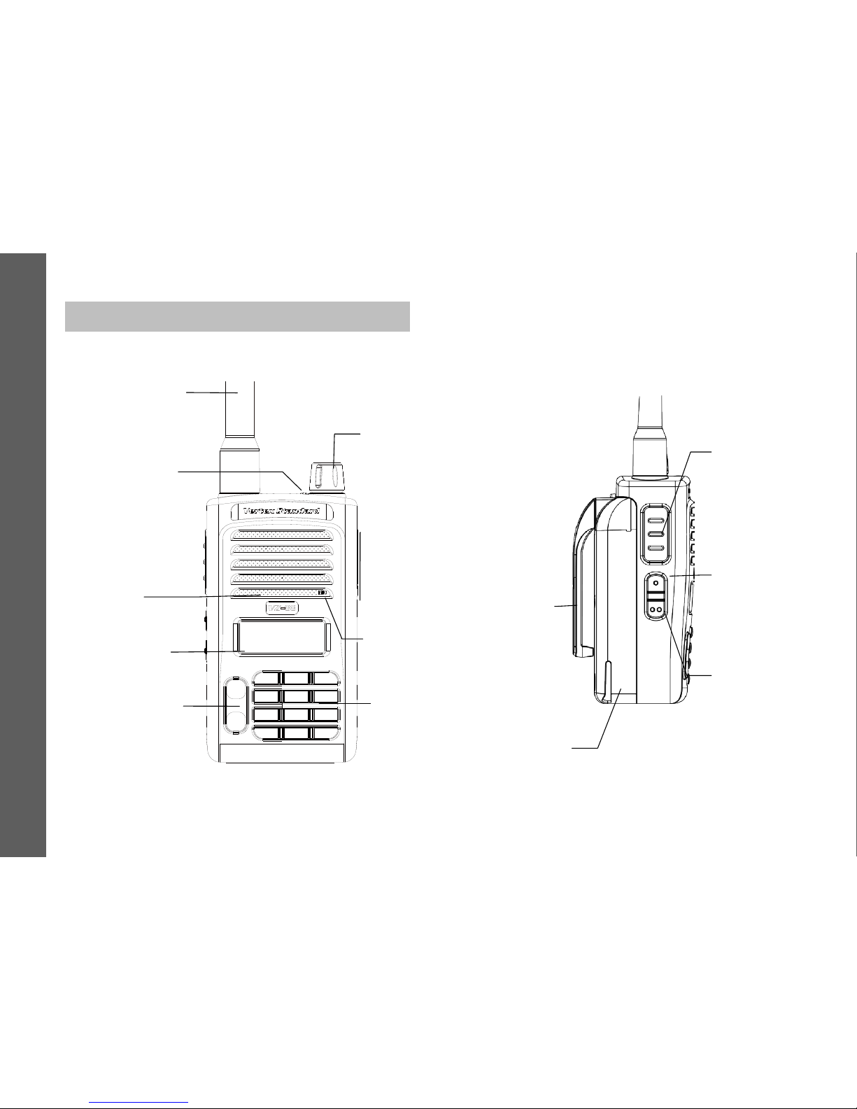
General Description
Familiarizing with VZ-88 Radio
Power/volume knob
Press to turn on/off
radio or adjust the
volume.
LED indicator
Turns red when TX at
high Power
Turns orange when TX
at low power
Turns green when RX
Microphone
Input voice
Keypad
To enter frequency or
short cut menu.
Speaker
Output voice
Up/Down button
Up/down to select
frequency or channels
or to select menu.
LCD display
indicate working status
Antenna
Rubber antenna
used to TX and RX.
Ear jack
External ear jack Or
programming cable
jack
PTT button
Press PTT to TX,
release PTT to
get ready for RX.
SB1
Programmable
side button 1
SB 2
Programmable
side button 2
Battery
Belt clip
16
General Description
Page 18

LCD Icons
On the LCD display, you will see different kinds of
icons. The below chart shows the description of these
icons:
Display frequency, channel number or menu
information in digits or letters.
Display the selected memory channel number, or
menu number in channel mode.
Receiving signal strength indicator: If the signal
strength is strong, the icon shows antenna and 6 bars.
If the signal strength is medium, the icon shows
antenna and 3 bars. If the signal strength is week, the
icon shows antenna only.
Other icon descriptions:
Icon Function description
1
battery indicator 4 bars
2
Auto power off
3
Scan
4
VOX
5
Key tone
6
High power TX
7
Repeater
8
Monitor when FM enabled
9
CTCSS (PL)
10
CDCSS (DPL)
11
Combination function
12
Power save
13
FM enabled
14
Key lock
17
General Description
Page 19
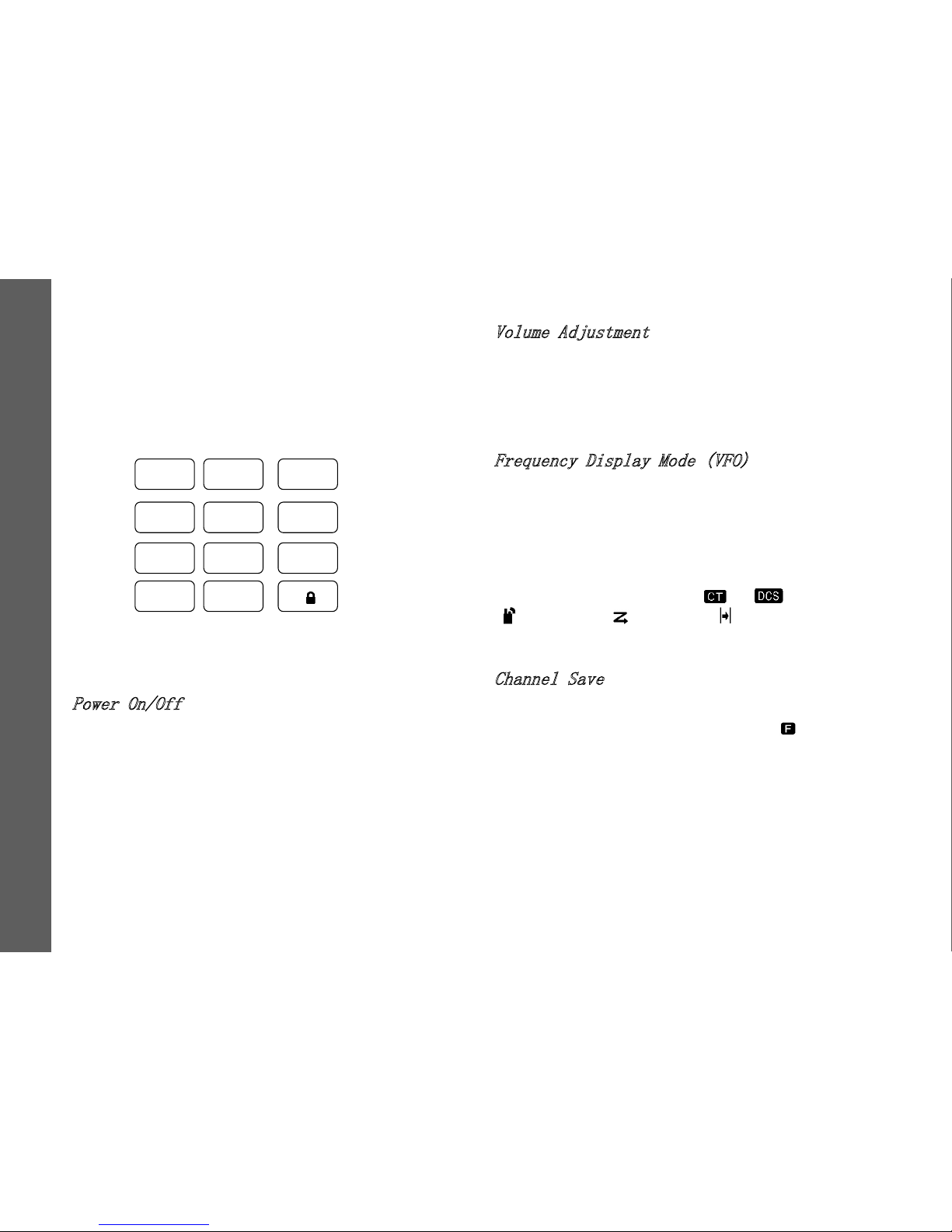
Digit Keypad
Channel number and Frequency can be input by digit
keys directly.
The letters marks on digit keys are the short cut key
function which can be reached by “F” key + digit key.
Basic Operations
Power On/Off
To turn the radio on, rotate the “ON/OFF/VOL” knob
clockwise. A click will be heard. The start tone sounds
and the LCD displays start up message. Then the radio
enters RX standby mode and the LCD shows the last
settings.
To turn the radio off rotate the “ON/OFF/VOL” knob
counterclockwise until a click is heard.
Volume Adjustment
Rotate the “ON/OFF/VOL” knob to adjust the volume
levels. To increase volume level, turn the rotary knob
clockwise. To decrease volume level, turn the rotary
knob counterclockwise.
Frequency Display Mode (VFO)
In VFO mode, the RX frequency is displayed which can
be increased or decreased by pressing “▲” /“▼” key
per frequency step setting, or it can be directly set by
entering the frequency numbers.
All VFO settings can be modified through menu or
short-cut, and icons such as “
” / “ ”, high power
“ ”,scan add “ ”,repeater “ ” indicate related
VFO settings.
Channel Save
To save current VFO Frequency & other settings into a
channel, press the “F” button, then icon “
” & channel
numbers blinks. Press “▲” / “▼” key to select the
channel number to save to, then press “V/M” key to
confirm the settings. Press “PTT” to exit this status.
Press “V/M” key to switch current radio operation mode
between VFO mode & MR mode.
1
SQL
2
PWR
3
SCAN
4
REP
5
REV
6
SQT
7
MODE
8
FM
9
SEL
V/M
0
LIST
F
18
General Description
Page 20
Channel Display Mode (MR)
The VZ-88 radio has 128 channels. The left bottom
side of the LCD displays “CH” and the current channel
number. The RX frequency or channel name is
displayed which is selected by pressing ”F”+”7MODE”
keys. The icons such as “
” / “ ”, high power
“
”,scan add “ ”,repeater “ ” indicate related
settings for the current channel.
Pressing “▲”/“▼” to change channel number
consequently. Either, channel can be directly selected
by entering the channel numbers.
FM Frequency Display Mode (FM VFO)
When FM is enabled, icon“ ”shows. The frequency
can be adjusted by pressing “▲” /“▼” key with 100KHz
per step, or directly by entering frequency numbers
from numeric keypad.
Note: FM Receiving frequency is from 87-108MHz.
FM Channel Save
To save current F M frequency into a FM channel,
press the “F” button, then icon “
” & FM channel
number blinks. Press “▲” / “▼” key to select the
channel number to save to, then press “V/M” key to
confirm the settings. Press “PTT” to exit this status. A
maximum of 25 FM channels can be set.
FM Channel Display Mode (MR)
Press “V/M” key to switch the FM VFO/MR mode. In
MR mode the LCD (left bottom) displays the FM
channel number 01 to 25. Use “▲/▼” key to change
FM channel or enter wanted channel number from
keypad directly.
Short Cut Key
Press the “F” key, when “ ” blinks then press digit
button to do a short cut operation, refer to chapter
“Short Cut Key”.
Menu Selection Mode(MENU)
Press ”F” key, then icon “ ” blinks in the display.
Press “9” key to select menu. In this mode, you may
select items by using “▲/▼”key, refer to Chapter 7.
Keypad Lock or Unlock
Press and hold the “F” key for 2s to lock the keypad,
the LCD displays “
” icon. Press and hold the “F” key
for 2s again to unlock the keypad.
Communication Requirement
When talking to each other, the 2 radios TX/RX
frequency, PL/DPL should match, means the TX
frequency and PL/DPL should be the same as the RX
frequency and PL/DPL. It is suggested the TX/RX is
19
General Description
Page 21
set with the same bandwidth to get good sound quality.
RX and Signal Strength Indication
When there is RF signal detected and strength over
the SQ squelch, the green indicator lights up shows RX,
and display signal strength icon “
”; If no RX
setting of CTCSS/DCS, then speaker enabled, or only
when CTCSS/DCS received and matched as well the
speaker can be enabled.
Calling and Monitor
It is important to monitor before calling for fear of
interference. Press the side button programmed as
MONITOR to check channel status. If there is no TX
signal in the channel, background noise will be heard.
Press it again to exit the monitor mode.
When talking on the channel ends, press “PTT” to start
calling. Keep the radio straight and at least 2.5cm
away from your nose or mouse, the antenna should be
far away from your eyes. When TX in high power the
LED indicator will show red, for low power mode the
LED indicator will show orange. Release the PTT
button to end speaking and the radio turns to RX
standby mode.
Hands Free / VOX
VZ-88 radio supports hands free (VOX) performance. It
will be better if using compatible VOX accessories.
Before VOX transmitting, adjust VOX sensitivity and
VOX delay time to a suitable level from the CPS or
VOX menu, and then do the following steps:
a. Turn audio accessory PTT switch to VOX side;
b. Plug VOX accessory into the accessory jack.
c. Turn down the radio volume before speaking;
d. Speak into the microphone to TX, stop speaking to
RX.
LCD Backlit
When the Light option is default “KEY”, pressing a key
on the front panel can light up the screen. If there is no
response after 5s after releasing “Light” button, the
light will be auto-off. When the light is on, press any
button except “Light” to restart the 5s timer, press
“Light” to turn off light immediately. If require light
always on, press “F” + “9” key to enter menu
selection mode and using “▲/▼” key to set the light.
Initialization
To set the radio settings to default please press and
hold PTT, SB2 and SB1 together when turning on the
radio until a chatter sound heard. For Default settings
please refer to VZ-88 CPS initial values.
20
General Description
Page 22
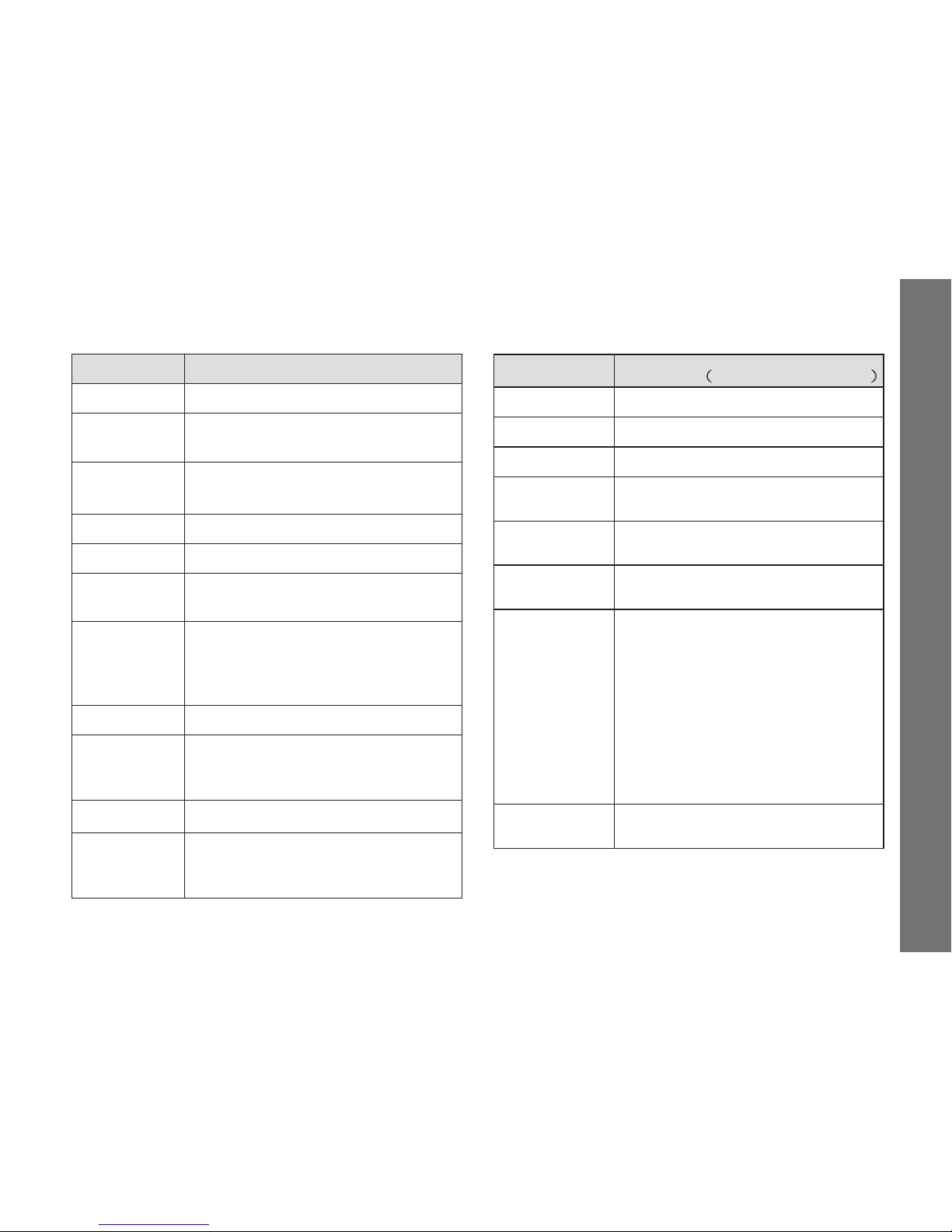
LED Indicator
Radio mode LED indication
Power on Red LED blinks 300ms
Power low Orange LED blinks 50ms every 2s,
gives low power alarm every 15 mins.
Standby
mode
Red LED blinks ( every 5s blinks
50ms)
Channel busy Green LED always on
Clone Orange LED always on
In cloning Master radio red LED blinks,
subsidiary radio green LED blinks.
Low voltage
and power off
Low voltage alarms every second, at
the same time orange LED blinks
twice per second. It powers off after
10 seconds
Monitor Green LED always on
Standby
programming
mode
Reading: red LED blinks fast; Writing :
green LED blinks fast
Scan mode Green LED blinks once every 0.6s
Sending voice Low power TX: orange LED always
on; High power TX: red LED always
on.
Tones
Tone type
Parameter(frequency _ duration)
Key tone 900Hz_75ms
Bad key tone 600Hz_75ms
Confirm tone 1800Hz_150ms
Function
enable tone
900ms_75ms
Function
disable tone
1800Hz_75ms
Power on tone
600Hz_75ms; 900Hz_50ms;
1200Hz_75ms
Low voltage
alarm tone
Beep 1.8KHz_50ms, off_40ms,
Beep again 1.8KHz_50ms;
Pause 180ms;
Beep 1.8KHz_50ms, off_40ms,
Beep again 1.8KHz_50ms,
Then stop.
It alarms every 15 minutes, if low
voltage at start up or end of TX, it
alarms instantly.
Low voltage
power off alarm
Low voltage alarm every second and
power off after 10s.
21
General Description
Page 23
Short Cut Keys
Pressing “F” then a digit key can reach below short-cut
Key functions quickly:
“F” + “1” SQL Squelch level
“F” + “2” PWR TX power
“F” + “3” SCAN Scan
“F” + “4” REP Repeater
“F” + “5” REV Reverse burst
“F” + “6” SQT Squelch technology
“F” + “7” MODE Channel display mode
“F” + “8” FM FM radio enable/disable
“F” + “9” SEL Menu setting
“F” + “0” LIST Channel scan list adding
Press “F” + “1SQL” key: To enter SQL level
setting menu.
Press “▲/▼” key to select SQL level from 0-9, press
“F” or “PTT” key to confirm and exit the setting mode,
press other key to go back to idle mode.
Press “F” + “2
PWR
” Key: To switch high / low
TX power.
When TX power is high, it will display the “ ” icon. To
save power, you may select low power TX.
Press “F” + “3
SCAN
” key: To enter scan
mode.
In FM VFO mode, the radio scans from FM frequency
87.0 to 108MHz, the scan stepping is 100 KHz. In FM
channel mode, saved FM channel frequency will be
scanned. If FM signal was detected, it will stop
scanning and stay in the active channel and listen.
Press “▲/▼”key to change scan direction or press any
other buttons to quit scanning.
In radio VFO mode, the unit scans in the frequency
range it supported, with selected frequency step
changing. In radio channel mode, the scan list
channels will be scanned. When channel bank is set,
only same bank channels are scanned.
When a channel/frequency signal is received and the
squelch is matching, it will stay in the channel and the
green LED will light up, press “PTT” to talk in that
channel. If you do not want to scan a channel, press
“Nuisance Delete” side button to skip the channel. The
channel won’t be scanned again during current
operation.
In scanning, the icon “
” appears. Press “▲/▼” key to
change scan direction, press PTT button to TX on
current channel, press “F” + “3” key again to exit scan
mode.
Press “F” + “4
REP
” key: To enable or disable
22
Short Cut Keys
Page 24

the repeater function.
When at different TX/RX frequencies, the repeater can
be enabled. The icon “
” is displayed as repeater is
enabled, and once pressing “F” + “4” keys, it will
change the repeater status. When the repeater stops it
is called “talk- around”, at that moment the TX
frequency & PL/DPL becomes same as the RX
frequency & PL/DPL.
Press “F” + “5
REV
” key: To set reverse burst.
While talking, release “PTT” to stop transmitting, there
is a harsh “ZaZa” sound heard by the RX user. Set
STE on can remove this noise.
There are 4 STE modes to select: frequency, phase
deviation 120°, phase deviation 180°, phase deviation
240°.
Note: This is effective only when the opposite radio has
the same STE mode.
Press “F” + “6SQT” key: To enter squelch
technology setting.
Display received PL/DPL for: no code as “R OFF”, PL
as “R 67.0” or DPL as “R 023N”, reversed DPL as
“R023I”.
Press “6
SQT
” key to shift from above 4 types of
squelch mode;
If it is PL, press “▲/▼” key to select from 50 groups
PL(refer to coding form)
If it is DPL normal code, press “▲/▼” key to select
from 104 groups N DPL.
If it is DPL reverse code, press “▲/▼” key to select
from 104 I DPL.
Press “F” key to confirm and enter PL/DPL TX
setting, but it’ll quit if current channel is at
talk-around mode; press “PTT” button to confirm
and quit.
Display transmitting PL/DPL for: no code as “R OFF”,
PL as “R 67.0” or DPL as “R 023N”, reversed DPL as
“R023I”.
Press “6
SQT
”key to shift from above 4 types of
squelch mode;
If it is PL, press “▲/▼” key to select from 50 groups
PL(refer to coding form)
If it is DPL normal code, press “▲/▼” key to select
from 104 groups N DPL.
If it is DPL reverse code, press “▲/▼” key to select
from 104 I DPL.
Press “F” key to confirm and quit, press “PTT”
button to confirm and quit.
Press “F” + “7
MODE
” key: To switch channel
display mode.
Enable it to switch channel display modes, display RX
23
Short Cut Key
Page 25

frequency or channel name.
Press “F” + “8FM” key: To turn On/Off FM
radio mode.
When turn on the FM radio mode, it will display “ ”
icon.
Press “F” + “9
SEL
” key: To enter menu
setting mode.
Press“▲/▼” key to select menu, then press “F” key to
set or press other button key to cancel setting.
Press “F” + “0
LIST
” key: To enter add scan
channel setting mode.
Current channel will be added to scan list or deleted by
operating it each time. When the current channel is on
scan list displays icon “
”
24
Short Cut Key
Page 26
Menu Setting
Menu List
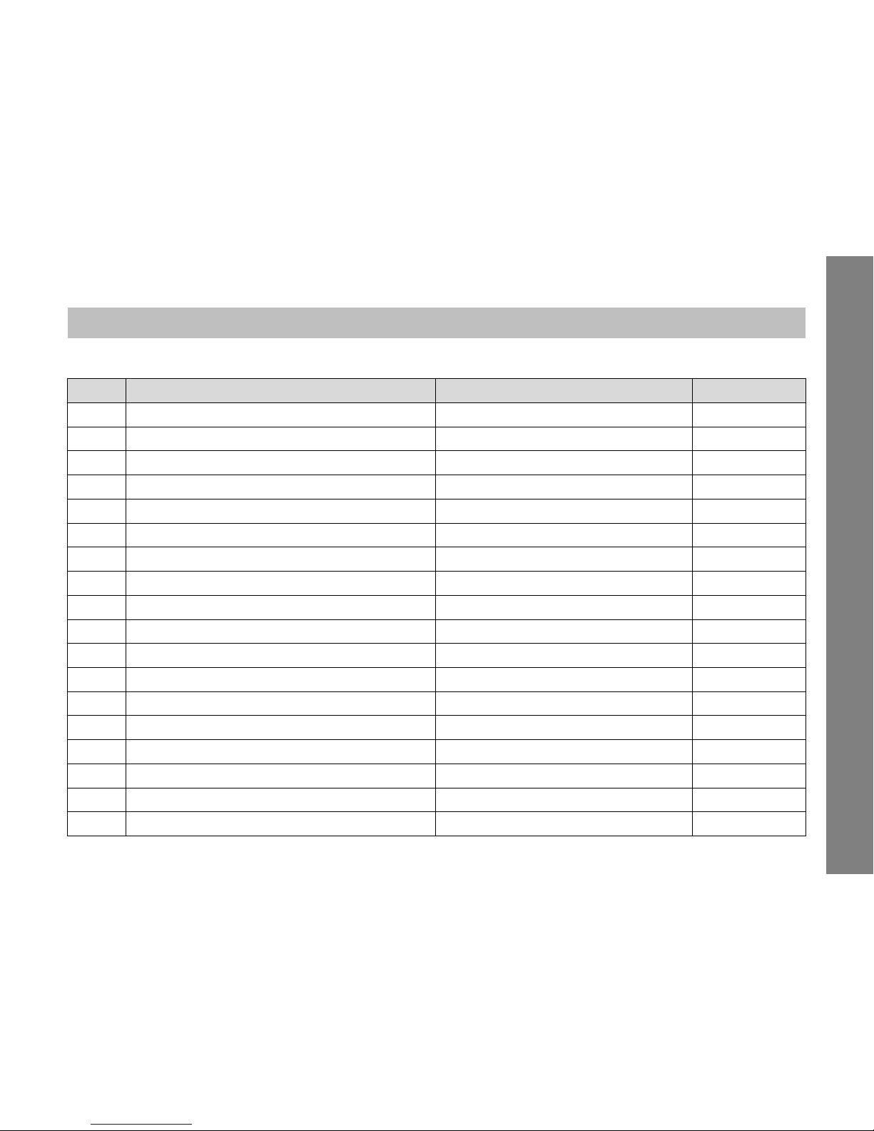
Items Display & Description Setting Content Default Setting
1
ALIAS - Channel alias
6 characters channel name edition No name
2
APO - Auto power off
ON/OFF OFF
3
BANK - 8 banks with 16 channels per bank
BANK n /NOBANK NO BANK
4
BATSAV - Battery saver
ON/OFF ON
5
BCLO – Busy channel lock out
ON/OFF OFF
6
BEEP - keypad tone
ON/OFF ON
7
BW - Radio band width
12.5K/25K 25K
8
DW - Dual watch RX signal in FM radio mode
ON/OFF ON
9
LIGHT - Light options
OFF/KEY/CONT KEY
10
LOCK – Key lock mode
K+S/PTT/KEY/ALL ALL
11
OPNMSG - Opening message
To edit open message for 6 char VZ SER
12
PSWD W - Password setting
To create a 4 digit password N/A
13
ROGER - End call tone
ON/OFF OFF
14
TOT - Time out timer
OFF, 30,60, … 270s 180
15
TXSTOP
ON/OFF OFF
16
VOX - voice control level
1~9 OFF
17
OFFSET – VFO TX freq. offset
00.000~+/-69.995MHz 00.000
18
STEP - VFO RX freq. step
5.00K, 6.25K, 10.00k,12.50K, 25.00K 25K
25
Menu Setting
Page 27
Menu Operation
Press “F” key, the “ ”icon will blink in the screen,
and then press “9” key to enter menu select mode .
Press “▲/▼” key to select required menu.
Press “F” key to enter setting, select contents by
pressing“▲/▼” key.
After setting, press “F” key to save and go back to
former menu, press “PTT” key to save. Cancel
setting by pressing any other buttons.
Menu item 17 & 18 are invisible when VFO function
is disabled, either, these 2 menu items can’t be
addressed in channel mode.
Menu Functions or Settings
ALIAS - Channel Alias
You can edit current channel alias, maximum 6
characters or letters.
Enter “ALIAS” menu, first digit blinks. use“▲/▼”
key to select “A”~“Z”、“-”、、“+”、“*”, “#” “0”~“9”、“_”or
a space.
Press “9”key to enter second digit editing.
Repeat step a,b until the 6th digit, press ”F” key to
save.
When editing, press “V/M” key to delete characters,
it displays 6 spaces. If the channel alias is empty,
channel name is displayed as default “CH-nnn”.
APO - Auto Power Off
APO is a background function, it can monitor if the
buttons were touched or valid RF signal is received. If
there is no response in 1 hour, APO works. 1 min
before APO, the “APO” icon will blink with a warning
tone.
If RX squelch function is opened or changed or any
other settings when APO is enabled, the timer will be
reset. If the muting function is closed or no other
settings occur, timer will go back to 0 and restart.
Channel BANK
When you use this function, all saved channels will be
banked automatically and display corresponding group
number for quick selection.
a. BANK: bank function enabled, 128 channels were
split into 8 groups:
BANK 1: 001-016 channels
BANK 2: 017-032 channels
BANK 3: 033-048 channels
BANK 4: 049-064 channels
BANK 5: 065-080 channels
BANK 6: 081-096 channels
BANK 7: 097-112 channels
BANK 8: 113-128 channels
b. NO BANK: To close bank function and display from
26
Menu Setting
Page 28
001 to 128 corresponding channel.
When banking function is enabled, the radio channel
number turns to “bxx”, “xx” refers to current group
serial numbers 01-16; press“▲/▼” key to shift from the
16 channels. Scan works on channels within group.
BATSAV – Battery Saver
BATSAV is on: When there is no signal received in RX
mode, it will reduce power consumption and extend the
power time. This function will be closed when in
Squelch situation or by pressing buttons. Select menu
“BATSAV” to On/Off BATSAV function. When this
function is enabled, icon “
” appears.
BCLO - Busy Channel Lock Out
BCLO: when the unit receiving a signal, TX is
forbidden for fear of interrupting the occupied busy
channel. Select menu “BCLO” to ON/OFF setting.
When the function is enabled, the PTT is unable to TX
and will give failure tone and will display “BCLO” icon.
BEEP – Key Tone Beep
The radio sounds “Beep” tone when pressing any
button. You may select menu “BEEP” to ON/OFF
setting.
BW - Band Width
To choose the needed bandwidth you can select “BW”
from the menu. Press “▲/▼” key to select 25K / 12.5K
(Hz), press “F” or “PTT” key to exit the setting mode,
press any other key to go back to idle mode.
DW - Dual Watch
When listening to the FM radio, if a TX signal is
received the FM radio will stop temporarily, the icon
“FM” blinks and the radio enters RX status. After the
signal has stopped for 5 seconds, the FM radio will
continue. You may select it from menu “DW” to
ON/OFF setting.
LIGHT Options
You may select menu “LIGHT” keypad or LCD screen
backlight operation.
OFF: keypad and LCD without backlight;
KEY: keypad and LCD backlight on and kept on for 5
sec by pressing any button, If no response,
backlight auto off. When keypad and LCD light is
on, press any button to restart the 5 second timer.
You may turn off the background light by
pressing “LIGHT” programmed side button.
CONT: LCD backlight is always on.
LOCK Mode Setting
Press “F” for 2 sec to lock the buttons when currently
not in use. The radio provides 4 kinds of lock mode,
you may select one by selecting menu “LOCK”.
27
Menu Setting
Page 29
K+S: To lock keypad and “up” and ”down” buttons.
PTT: To lock PTT button only for preventing un-proper
TX or false transmitting.
KEY: To lock keypad only, for preventing
unintentionally press of keypad.
ALL: All keys to be locked except ”F” key.
OPNMSG – Opening Display Message
You may set the start screen message, Max 6 numbers
or letters available.
Enter “OPNMSG” menu, first character blinks.
Press“▲/▼”key to select from “A”~“Z”、“-”、、“+”、
“*”, “#” “0”~“9”、“_”or a space.
Press “9”key to enter second character editing.
Repeat step b, c until 6th character, then press “F”
key to save.
Press “V/M” key to delete edit characters.
PSWD – Password Setting
Enter “PASSWD” menu to set the 4-digit password. If
you need to re-enter, you can use “V/M” to delete.
Press “F” key to save the new password. If the
password was deleted, there is no password protection
when radio is up.
Note: Please do not forget your password, if forget,
please contact your local distributor.
ROGER Setting
Select “ROGER” menu to ON/OFF roger beep.
TOT (TX Time- out - timer) Setting
Time out timer will protect the radio from damages
caused by uncertain transmitting. It can be set: OFF,
30s, 60s…270s, when it times out it gives a warning
and stop transmission. Enter “TOT” menu and press
“▲/▼” key to select.
TXSTOP Setting
TXSTOP is to protect the radio from false TX or
unauthorized TX. Enter “TXSTOP” menu to turn
ON/OFF this function.
VOX Setting
VOX function is to TX by speaking without pushing the
PTT button.
Enter “VOX” menu, press “▲/▼” key to disable or
enable the VOX. Set the sensitivity to “OFF”, 1 to 9
(level 9 is at maximum sensitivity). When this function
is enabled, icon“
” appears.
Note:
When VOX function is enabled: Speak into
microphone, Voice TX’s automatically; Stop
speaking, TX stops and is ready for RX.
Please select a suitable sensitivity level before
28
Menu Setting
Page 30
using this function. For different people tones are
different.
If the microphone is much too sensitive, noise from
surrounding areas may enable the TX, please
adjust sensitivity to a lower level.
If VOX gain is set to a high/sensitive level,
connecting the speaker/microphone to the radio
can amplify the RX signals and may cause TX.
OFFSET – VFO frequency offset
When offset frequency equals VFO TX frequency
minus RX frequency. The offset can be 00.000 to
69.995 MHz which is directly input by digit keys, and
the offset direction is selected by “▲/▼” keys for 3
options: none, “-“, and “+”. The positive (“+”) direction
means TX frequency will plus the offset on the current
displayed RX frequency, so as to the negative (“-“)
direction.
If the offset is set, the unit’s TX frequency display will
change when press “PTT” to transmit at repeater
mode.
STEP – VFO frequency step
Frequency step has 5 selections: 5.00KHz, 6.25KHz,
10.00KHz, 12.50KHz, and 25.00KHz. In VFO mode,
user can press “▲/▼” keys to increase / decrease RX
frequency with selected step.
CPS
It’s quite convenience to program following parameters
or functions by connecting the radio to a PC with a
compatible programming cable and run the VZ-88 CPS
program.
Channel Information setting
VZ-88 Radio has 128 channels, these channels can be
programmed by CPS, below parameters of each
channel can be set as well:
● RX Frequency ● TX Frequency
● RX PL/DPL ● TX PL/DPL
● Busy Lock ● TX Stop
● Roger Beep ● Band Width
● TX Power ● Talk-Around / Repeater
● PTT ID ● Alias
VFO Information setting:
Enable/Disable VFO feature via CPS. The default
setting is Enable and support FPP function.
Following VFO parameters are set by CPS:
● VFO Function Enable ● RX Freq.
● RX PL/DPL ● TX PL/DPL
● Busy Lock ● TX Stop
● Roger B eep ● Band Width
● TX Power ● Talk-Around / Repeater
● PTT ID ● Freq. Step
● Offset Freq. ● Offset Mode
29
CPS
Page 31
Function parameter setting
User may set the following parameters by CPS:
Squelch level TX time out timer
Scan Dwell Time Reverse Burst
Channel Display Mode Back Light
Key Lock Mode Work Mode
Key Tone Power Saver
Auto Power Off Bank
VOX Sensitivity VOX Delay Time
●
●
●
●
●
●
●
●
Opening Display Message Password PIN
DTMF setting
DTMF side tone PTT ID
Pre-Only Code Post-Only Code
DTMF Speed First digit time
First digit delay time
FM function setting
Enable FM Function DW (Dual Watch)
FM working mode FM VFO Frequency
Enable FM Function DW (Dual Watch)
25 channels Frequency list (87.0 – 108MHz)
Scan List
Available channels can be added into scan list, or
delete channel number from scan list.
Programmable side button
User can set side button 1, 2 (long press/short press)
as bellow functions:
None Monitor
scan On/Off Nuisance Delete
High/Low Power Talk-around/Repeater
Back Light On/Off
Monitor
When enabled, the monitor button will give out squelch.
It is to check if current channel have been occupied
and will temporarily get rid of the CTCSS/DCS,
meanwhile it will receive some week signals.
Scan On/Off
Scan on: Touch the programmed side button, it starts
from current channel. When a channel receives signal
and squelch type is matching, the green LED indicator
lights on and stays in current channel.
Scan off: Touch the side button again to quit scanning.
Nuisance Delete
Sometimes scanning will stay in a nuisance channel,
press “Nuisance delete” to delete the channel
temporarily from the scanning list, it won’t be scanned
again in current operation. Enable scanning again and
it will be added to the list.
High/Low Power
Shift from high/low power mode by enabling the
programmable button as high/low.
30
CPS
●
●
●
●
●
●
●
●
●
●
●
●
●
●
●
●
●
●
●
●
●
●
●
●
●
●
●
●
●
Page 32
Talk-around/Repeater
Enable the programmable side button REPEATER to
change the current channel repeater status. When
enabled, it displays the icon “
”. When the repeater
stops it is called talk around, at this time TX frequency
becomes the same as RX frequency, and TX PL/DPL
becomes the same as RX PL/DPL.
Back Light On/Off
Press light button to turn ON/OFF backlight.
Clone Function
You may use CPS read/write operation to clone
settings from one radio (master radio) to another
(target radio).
The Steps of Clone Operation:
a. Press and hold 【PTT】 & Side button1 as power on
till “DI-“ sounds, then release the 2 buttons and
“CLONE” is displayed. The master light is on
indicating. the radio is ready for cloning.
b. Connect the target radio to the master radio by
cloning cable, turn the target radio on.
c. Press the PTT button of the master radio, its red
light blinks and meanwhile the target radio with
green light blinks shows cloning; after about 28s
finish cloning, the master radio resets and waits for
next cloning request, the target radio resets
automatically.
d. If cloning failed, the master radio will display “ERR”,
and the target radio reset automatically. Then press
the master radio【PTT】 button, the master radio
displays “CLONE” again. Check if the cable is well
connected and repeat step c.
e. If more radios need to clone, please power off the
target radio and replace another radio, then repeat
step b & c.
f. To quit cloning, please power off the radio and
re-start again.
31
Clone Function
Page 33

PL/DPL Frequency/Code Table
Standard PL (CTCSS) Frequency (Hz) Table:
1 67.0 11 94.8 21 131.8 31 171.3 41 203.5
2 69.3 12 97.4 22 136.5 32 173.8 42 206.5
3 71.9 13 100.0 23 141.3 33 177.3 43 210.7
4 74.4 14 103.5 24 146.2 34 179.9 44 218.1
5 77.0 15 107.2 25 151.4 35 183.5 45 225.7
6 79.7 16 110.9 26 156.7 36 186.2 46 229.1
7 82.5 17 114.8 27 159.8 37 189.9 47 233.6
8 85.4 18 118.8 28 162.2 38 192.8 48 241.8
9 88.5 19 123.0 29 165.5 39 196.6 49 250.3
10 91.5 20 127.3 30 167.9 40 199.5 50 254.1
32
PL/DPL Frequency/Code Table
Page 34
Standard DPL (CDCSS) Code Table:
1 023 16 074 31 165 46 261 61 356 76 462 91 627
2 025 17 114 32 172 47 263 62 364 77 464 92 631
3 026 18 115 33 174 48 265 63 365 78 465 93 632
4 031 19 116 34 205 49 266 64 371 79 466 94 654
5 032 20 122 35 212 50 271 65 411 80 503 95 662
6 036 21 125 36 223 51 274 66 412 81 506 96 664
7 043 22 131 37 225 52 306 67 413 82 516 97 703
8 047 23 132 38 226 53 311 68 423 83 523 98 712
9 051 24 134 39 243 54 315 69 431 84 526 99 723
10 053 25 143 40 244 55 325 70 432 85 532 100 731
11 054 26 145 41 245 56 331 71 445 86 546 101 732
12 065 27 152 42 246 57 332 72 446 87 565 102 734
13 071 28 155 43 251 58 343 73 452 88 606 103 743
14 072 29 156 44 252 59 346 74 454 89 612 104 754
15 073 30 162 45 255 60 351 75 455 90 624
33
PL/DPL Frequency/Code Table
Page 35
C Z U G 0 0 0 0 3 0
Copyright 2013
 Loading...