

Page 1
VXR-7000
Operating Manual
Vertex Standard LMR, Inc.
Page 2

Page 3

English
Page 4

Contents
Introduction ............................................................................................................................ 1
Controls & Connectors ......................................................................................................... 2
Front Panel........................................................................................................................................ 2
Rear Panel ......................................................................................................................................... 3
ACC Connector Port ..............................................................................................................4
LINE Interface Port................................................................................................................ 6
Installation .............................................................................................................................. 7
Antenna Considerations ................................................................................................................. 7
AC Power Supply Voltage Selection ............................................................................................. 7
DC Power Supply Backup .............................................................................................................. 7
Equipment Location ........................................................................................................................ 7
Changing Switching Regulator unit AC Mains Jumper Wiring .......................................... 8
CE27 Programming Software Instruction ....................................................................... 10
Channel Data Items ....................................................................................................................... 11
Duplexer Installation .......................................................................................................... 14
Specifications ....................................................................................................................... 16
Accessories ............................................................................................................................ 17
Page 5
Introduction
The VXR-7000 is commercial quality 50-watt FM repeater designed to provide reliable, continuous-duty two-way
communications over a wide range of environmental conditions.
Designed to be a stylish base station, with high-grade components utilized throughout, the VXR-7000 utilizes the
latest computer-aided design and manufacturing processes to ensure a high level of reliability for users. Important
channel frequency data is stored in EEPROM, and is easily programmable by a Servicing Technician or Dealer using
an IBM compatible personal computer and the FIF-10A (or FIF-12) + CT-104A USB Programming Interface and CE27
Software.
Please take a few minutes to read this manual carefully. The information presented here will allow you to derive
maximum performance from your VXR-7000. After reading it, keep this manual handy for quick reference, in case
questions arise later on.
Important Note: Internal service work, programming, and accessory installations should only be performed by your
authorized Vertex Standard Dealer. Dangerous conditions and/or possibly illegal operation may result from improper setup, programming, or internal modifications.
VXR-7000 FM REPEATER OPERATING MANUAL 1
Page 6
Controls & Connectors
Front Panel
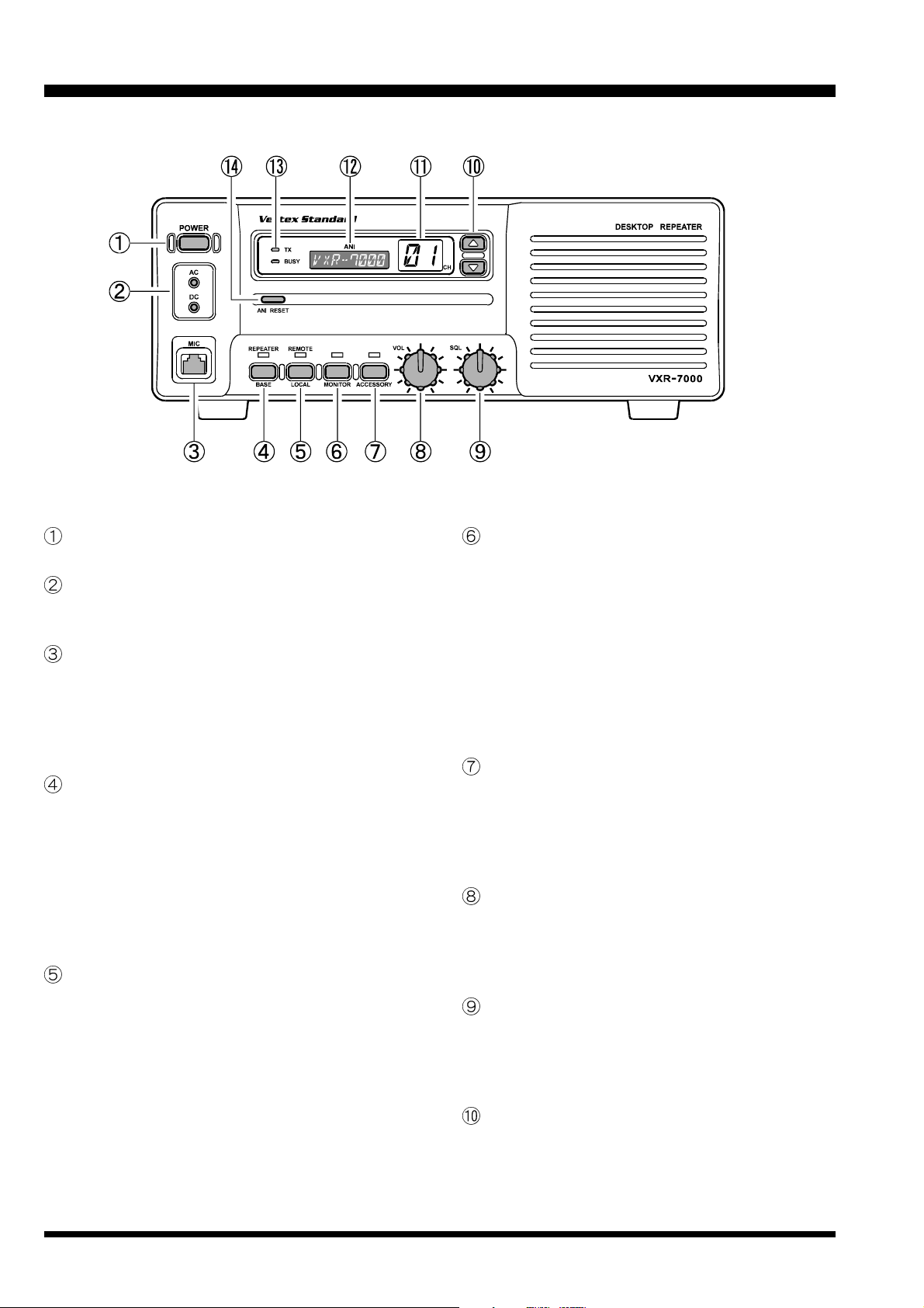
POWER Switch
This is the main power switch for the repeater.
LED Indicators
AC: This LED glows green during AC operation.
DC: This LED glows yellow during DC operation.
MIC Jack
This 8-pin modular jack accepts the microphone input, and provides a standby control line to activate
the transmitter when using the “BASE” mode of
operation. This jack also provides a “Hook” control
line, as well as a “Clone Data” line.
BASE/REPEATER Switch
This switch toggles the operating mode between the
“REPEATER” mode and the “BASE” transceiver
mode. When the “REPEATER” mode is selected, the
LED above it glows green. While in the “BASE”
mode (the green LED is off), you can speak into the
microphone to use it as a transceiver. For normal
repeater operation, set this switch to the “RE-
PEATER” mode.
LOCAL/REMOTE Switch
This switch toggles the control mode between the
“REMOTE” mode and “LOCAL” mode. When the
“LOCAL” mode is selected, the LED above it is off,
and the repeater operates according to the control
data programmed into the repeater. While in the
“REMOTE” mode, the LED glows green, and the
repeater operates according to the control instructions received from an external device (connected
to the ACC jack on the rear panel).
MONITOR Switch
This switch selects the “Squelch” (receiver mute)
mode. When the green LED above it is off, “Tone”
or “Coded” squelch is active. When you press this
switch momentarily, the green LED will glow
steadily; in this condition, only “noise squelch” is
active, and any signal present on the channel will
be heard. If you press and hold this switch for more
than 2 second, the green LED will blink and the
squelch will open; in this condition, background
noise will be heard if no signal is present.
ACCESSORY Switch
This switch can be set up for special applications,
such as High/Low power selection, as determined
by your Vertex Standard dealer. The LED above it
glows green when this function is activated. For further details, contact your Vertex Standard dealer.
VOL Knob
This control knob adjusts the receiver volume level
from the front panel speaker. If desired, this control
knob may be set fully counterclockwise when repeater monitoring is not needed.
SQL Knob
This control knob selects the noise squelch threshold level. Set it to a position just above the point
where the BUSY lamp goes out when no signal is
present.
Channel Selector Buttons ( and )
Press one of these buttons to select the operating
channel.
VXR-7000 FM REPEATER OPERATING MANUAL2
Page 7

Controls & Connectors
Channel Indicator
This seven-segment LED indicates the operating
channel number.
ANI Display
The ANI LCD (Liquid Crystal Display) indicates the
pre-programmed ANI message according to the
ANI code received.
TX/BUSY Indicator
The BUSY indicator glows green when the channel
is busy, and the TX indicator glows red when the
repeater is transmitting.
Rear Panel
ANI RESET Button
(1) ANI
Press this button to clear the message on the ANI
display, and turn off the LCD backlight.
(2) ENI
Press this button to turn off the Alert tone.
Press this button again to clear the message on
the ANI display, and turn off the LCD backlight.
EXT SP Jack
This 3.5-mm, 2-pin jack provides variable audio
output for an external speaker. The audio output
impedance at this jack is 4 Ω ~ 16 Ω, and level varies
according to the setting of the front panel’s VOL control.
TX Antenna Jack
This N-type coaxial jack provides the transmitting
output signal for connection to the transmitting antenna or TX jack on the duplexer, if used. The output impedance requirement is 50 Ω.
RX Antenna Jack
This N-type coaxial jack accepts the receiver input
signal from the receiving antenna or RX jack on the
duplexer, if used. The input impedance requirement
is 50 Ω.
ACC Jack
This DB-25 connector provides a data interface between the microprocessor in the VXR-7000 and peripheral devices (such as the VX-TRUNK Unit).
LINE Jack
This 8-pin modular jack is used for remote control.
It provides TX and RX audio, TX keying, and
squelch status output. The TX and RX audio impedance is 600 Ω.
GND Terminal
For best performance and safety, the GND terminal
should be connected to a good earth ground using
a short, heavy, braided cable.
AC Jack
This receptacle accepts the AC power cord, which
should be connected to the AC mains supply or wall
outlet. The AC line voltage must match that for
which the repeater is wired.
BATT Terminal
These terminal posts accept 12~ 15 VDC for operating the repeater from a battery or other DC source.
When operating from AC mains, a small trickle current is present at these terminals to maintain battery charge. A battery rated for 12 volts, 55 Ah (minimum) is recommended for short-term emergency/
backup operation.
Never short-circuit these terminal while operating
from AC mains.
VXR-7000 FM REPEATER OPERATING MANUAL 3
Page 8
ACC Connector Port
The VXR-7000 repeater is provided with a 25-pin DB25F female connector for interconnections to accessories. Use a DB-25M 25-pin male connector to connect
accessories to the repeater. The pins on the accessory
connector are explained in detail as follows:
Pin 1: GND
Chassis ground for all logic levels and power supply return.
Pin 2: +13.8 V [Power Supply]
This pin provides 13.8 Volts, 1.0 A, regulated DC
from the repeater supply. Use a 1 A fuse in the external device’s DC line to prevent damage to the repeater.
Pin 3: TX AF IN [Analog Transmitter Input]
(Voice Band: 300 ~ 3,000 Hz)
Input impedance is approx. 600 Ω. This audio is injected before the splatter filter stage, so excess signal input levels are clipped.
Use shielded cable to connect to this pin, and connect the shield to GND.
Pin 4: TONE IN [Transmitter Input]
(Sub-audible Band: 6 ~ 250 Hz)
The input is high impedance (approx. 22 kΩ). Injecting too high a voltage here causes over-deviation of CTCSS or DCS, degrading performance. Use
shielded cable to connect to this pin, connecting the
shield to GND.
Pin 5: N.C. (No connection.)
Pin 6: DISC OUT [Analog Output]
(Wide-Band: 0 ~ 3,000 Hz)
Received signals with standard deviation produce
approx. 1 Vp-p audio at this pin. The output impedance is approx. 600 Ω, and is extracted before the
de-emphasis and squelch circuitry. Use shielded
cable to connect to this pin, and connect the shield
to GND.
Pin 7: GND
Chassis ground for all logic levels and power supply return.
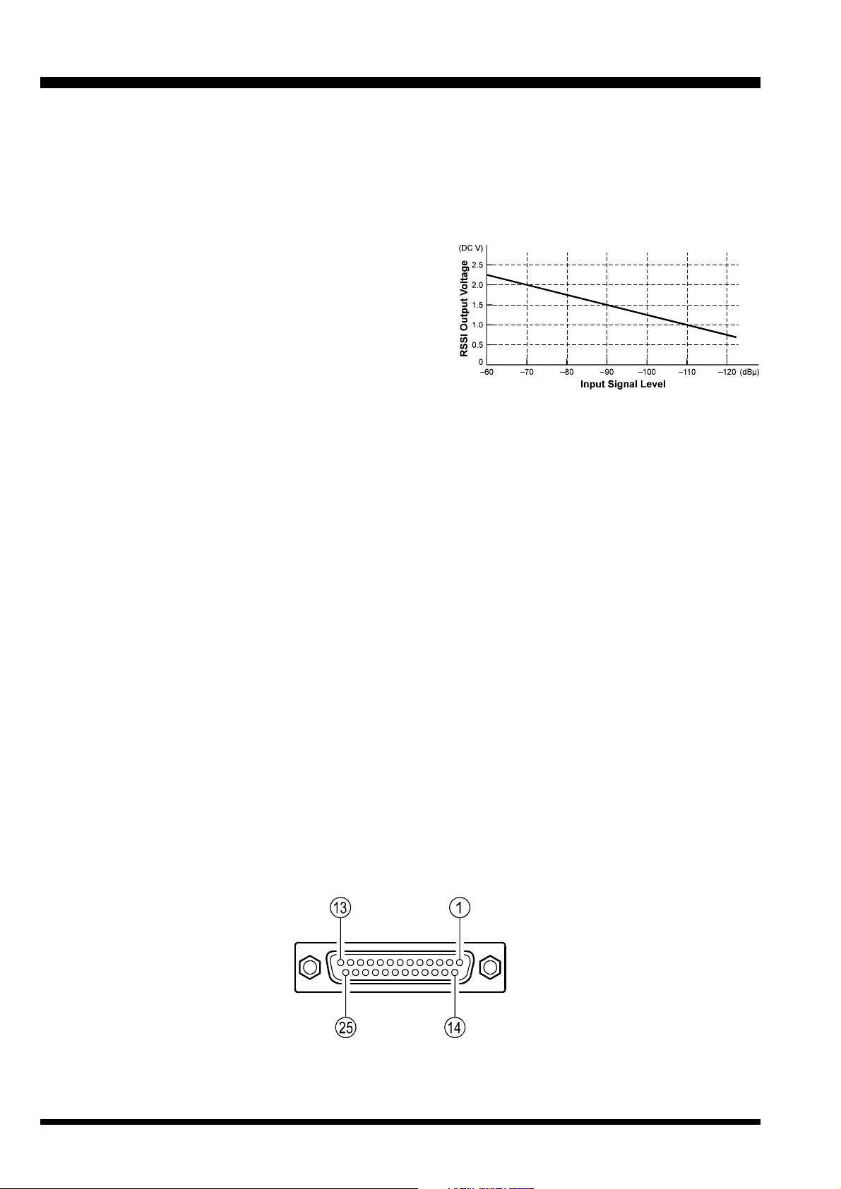
Pin 8: RSSI [Analog Output]
A DC voltage proportional to the strength of the signal currently being received (Receiver Signal
Strength Indicator) is provided on this pin. This low
impedance output is generated by the receiver IF
sub-system and buffered by an internal op-amp.
Typical voltages are graphed as follows:
Pin 9: COAX. SW [Logic Output (Active Low)]
This output is intended for controlling an external
coaxial switching relay. It is an open collector output which can sink approx. 10 mA when active. This
signal only switches if the repeater has been programmed for “SIMPLEX” mode. If programmed
for “DUPLEX,” the signal remains open (high impedance) at all time.
Pin 10: N.C. (No connection.)
Pin 11: NSQ DET
This is an open-collector, active-low output capable
of sinking about 10 mA. It indicates that the receiver
squelch is open. If the squelch control is properly
set, this indicates a carrier on the receiver channel.
Pin 12: EXT PTT
This input is internally pulled up to 5 VDC. When
pulled low by an external device, it keys the repeater
transmitter while the repeater is operating in the
“BASE” mode. Avoid voltage in excess of 5 V on
this pin, or internal damage to the microprocessor
on the repeater CNTL Unit may result.
ACC Jack
DB-25 Pin Numbering
VXR-7000 FM REPEATER OPERATING MANUAL4
Page 9
ACC Connector Port
Pin 13: GND
Chassis ground for all logic levels and power supply return.
Pin 14: GND
Chassis ground for all logic levels and power supply return.
Pin 15: N.C. (No connection.)
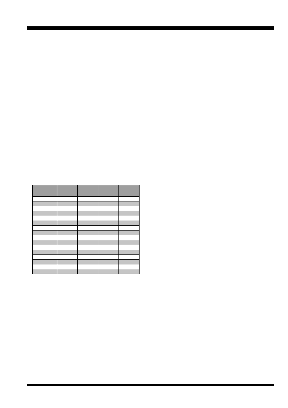
Pin 16, 17, 18, & 19: REMOTE CH DATA
[Logic Inputs D3, D2, D1, and D0] (Active Low)
These inputs are internally pulled up to 5-V DC.
When pulled low by an external device, they select
one of the 16 pre-programmed repeater operating
channels. The logic truth table below shows the combinations for selecting all 16 channels.
In the truth table, “1” represents no connection, and
“0” represents a ground connection on the pin.
The channel selection logic is not inhibited while
the transmitter is keyed: the repeater will change
frequency when instructed, even while transmitting.
Avoid voltage in excess of 5 V on these pins or internal damage to the microprocessor on the repeater
CNTL Unit may result.
Channel
1
2
3
4
5
6
7
8
9
10
11
12
13
14
15
16
Pin 16
(D3)
1
1
1
1
1
1
1
1
0
0
0
0
0
0
0
0
Pin 17
(D2)
1
1
1
1
0
0
0
0
1
1
1
1
0
0
0
0
Pin 18
(D1)
1
1
0
0
1
1
0
0
1
1
0
0
1
1
0
0
Pin 19
(D0)
1
0
1
0
1
0
1
0
1
0
1
0
1
0
1
0
Pin 20: GND
Chassis ground for all logic levels and power supply return.
Pin 21: A-OUTPUT [Logic Output] (Active Low)
This open collector logic output is pulled low when
the front panel’s ACCESSORY key is turned on. It
can sink approx. 10 mA when active.
Pin 22: RXD LOW
[Digital Output for DATA Communications]
(300 ~ 3,000 Hz)
This pin is an output for low speed receiving data
signals, with the data being extracted after the deemphasis and low pass filter stages.
Pin 23: RXD HI
[Digital Output for DATA Communications]
This pin is an output for high speed receiving data
signals, with the data being extracted immediately
after the discriminator prior to any de-emphasis).
Pin 24: TXD LOW
[Digital Input for DATA Communications]
(300 ~ 3,000 Hz)
This pin is intended to be used as a low speed digital data signal input to the repeater. This digital data
signal is injected before transmitter pre-emphasis
and limiting stage, so excess signal input levels are
clipped.
Pin 25: TXD HI
[Digital Input for the DATA Communications]
This pin is intended to be used as a high speed digital data signal input to the repeater. This digital data
signal is injected after transmitter splatter filter stage.
VXR-7000 FM REPEATER OPERATING MANUAL 5
Page 10
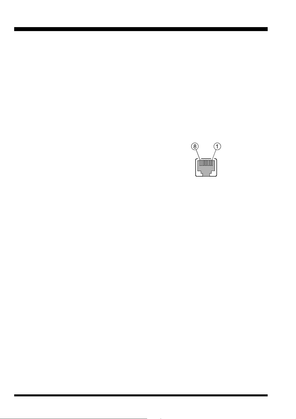
LINE Interface Port
The VXR-7000 is provided with an 8-pin modular jack
for line interfacing applications. A Western Electric
modular-type RJ45 plug should be used to connect to
this jack. The LINE jack pin-out is shown below.
Note that there are both 4-line and 8-line types of modular plugs. If a 4-line modular plug is used, only the LINE
OUT and LINE IN connections will be made. An 8-line
plug is required to access all lines. In accordance with
standard telecommunications interface, the line connections on the LINE interface jack are impedance balanced,
and are described as follows.
Pins 1 & 2: [RX SQ(+), RX SQ(–)]
An opto-isolator is provided to facilitate E (EAR)
signaling. The opto-isolator comes on when a signal exceeding the receiver squelch appears on the
receiver channel (with correct CTCSS tone or DCS
code, if enabled). The RX SQ(–) pin is the emitter,
and RX SQ(+) is the collector.
Maximum Voltage: 20 V, Maximum Current: 7 mA.
Pins 3 & 4: [LINE IN (Tx Line Audio)]
Analog signals between 300 and 3000 Hz supplied
to this pair are fed to the transmitter when the repeater is set to the BASE mode (the REPEATER LED
is turned off) and keyed either by the TX KEY input
signal (see below), or by the EXT PTT signal on pin
12 of the rear panel’s ACC jack. Standard deviation
is obtained with a line level of –10 dBm.
®
Pins 5 & 6: [LINE OUT (Rx Line Audio)]
Receiver audio is available from this pair, subject to
internal CTCSS or DCS decode if the received signal strength is above the squelch threshold.
As shipped from the factory, a 1-kHz receiver signal with standard deviation gives –10 dBm on the
line, but this can be varied by VR4002 and S4001
(on the repeater’s CNTL Unit).
Pins 7 & 8 [TX KEY(+), TX KEY(–)]
An opto-isolator is provided to facilitate M (MIC)
signaling. That is, a voltage presented to these pins
turns on the opto-isolator and keys the transmitter.
The TX KEY(+) pin is the anode of the opto-isolator,
and RX SQ(–) is the cathode of the opto-isolator.
Maximum Voltage: 20 V, Maximum Current: 4 mA.
LINE Jack
Modular Jack Pin Numbering
VXR-7000 FM REPEATER OPERATING MANUAL6
Page 11
Installation
Antenna Considerations
Repeater operation without a duplexer requires that two
antennas be installed, one for receiving and one for
transmitting, so that the receiving antenna does not absorb energy from the transmitting antenna. There are a
number of ways to do this, depending on the TX/RX
frequency separation, and on the locations available for
antenna mounting. If a duplexer is used, a single antenna suffices for both transmitting and receiving. If
using a reduced-size duplexer, a six-cavity model (minimum) is recommended. Vertex Standard recommends
the use of the duplexer. For further details, contact your
Vertex Standard dealer.
Regardless of the above choice, it is of paramount importance that the antenna(s) be mounted as high and in
the clear as possible, preferably within line-of-sight to
all repeater users. Furthermore, losses in the feedline(s)
must be minimized, so the feedline(s) should be high
quality, and as short as possible. If a long feedline is
necessary, use coaxial “hardline” cable to reduce losses.
Repeater antennas should have an impedance of 50 Ω
at the operating frequency. When separate receive and
transmit antennas are used, high-Q narrow-band types
may serve to minimize interaction. However, when a
single antenna is used with a duplexer, it should be a
low-Q wide-band type.
NEVER TRANSMIT WITHOUT HAVING A
TRANSMIT ANTENNA CONNECTED TO THE
TX ANTENNA JACK OF THE REPEATER.
AC Power Supply Voltage Selection
Each repeater is wired for a particular AC mains voltage between 100 and 253 VAC. This should be indicated
by a label near the AC jack on the rear panel. If no label
is present, or if the AC voltage on the label is different
from the local AC line, check the wiring inside the
Switching Regulator Unit of the repeater, and change
the connections (and label) if necessary, as shown next
page.
Changing the AC input voltage wiring also requires
changing the fuse on the FILTER Unit if the voltage is
changed from 100 VAC (100-127 VAC) to 200 VAC (207253 VAC), or vice-versa. Use a 5-amp fuse for 100 VAC,
or a 3-amp fuse for the 200 VAC.
DC Power Supply Backup
For uninterrupted operation during power failures, a
12 volt rechargeable type battery (55-Ah or more recommended) may be connected to the BATT terminal
posts on the rear panel. While the repeater is operating
from the AC source, a slight charging current will maintain battery charge. In the event of an AC power outage, the automatic power control circuit will automatically switch the repeater to the backup battery, and operation will not be interrupted.
After prolonged operation from the battery, it should
be disconnected from the repeater and recharged separately before re-connecting, as the trickle charge is not
sufficient for recharging a completely discharged battery.
Never reapply AC power to the repeater with a discharged battery connected, as the DC startup current
can damage the repeater and battery.
While operating from a battery or DC supply, the repeater requires approximately 7 amperes at 12 Volts during transmit.
Equipment Location
While the operating temperature range of the repeater
is quite broad, the best location is one in which the air
temperature does not approach the extremes of the
specified range, and one that does not change rapidly.
Make sure to allow for free air flow around the heatsink
on the rear apron at all times. In warm climates, the repeater should not be sealed in a small closed room.
Protect the repeater from wind and rain, and extremes
in temperature or humidity that may shorten the useful
life of the equipment. Try to locate the repeater in an
environment that is also comfortable for service personnel, if possible.
VXR-7000 FM REPEATER OPERATING MANUAL 7
Page 12
Installation
Changing Switching Regulator unit AC Mains Jumper Wiring
Before attempting this jumper wire change, remove the
AC power cord from the AC jack on the rear panel.
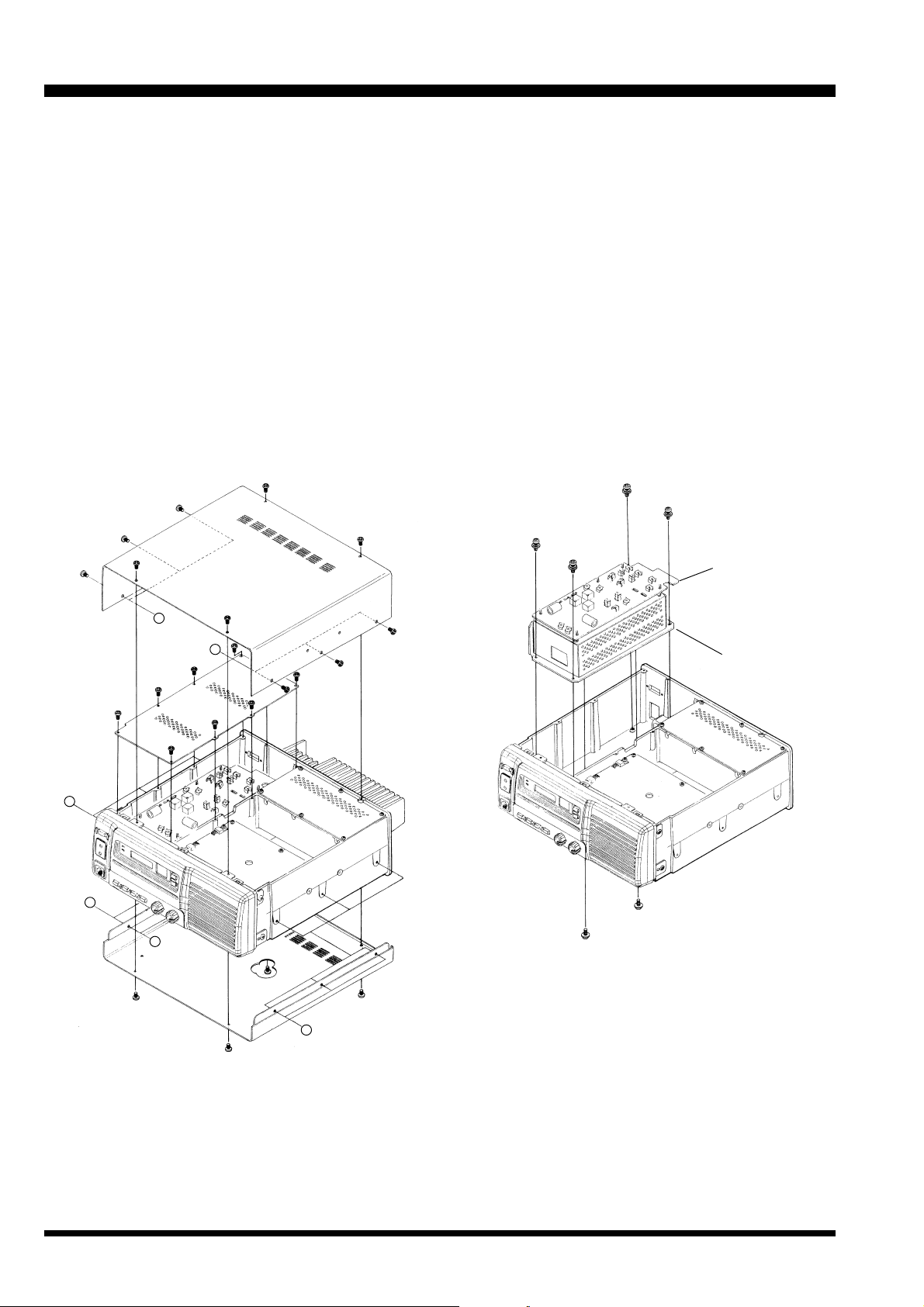
Referring to Figure 1, remove the 14 screws affixing
the top and bottom covers of the repeater, and remove the covers.
Remove the eight screws affixing the shield cover
for the FILTER Unit, and remove the cover (see Figure 1).
Disconnect all wires and connectors from the FIL-
TER Unit, then remove the six screws affixing the
Switching Regulator Unit, and remove it (the Switching Regulator Unit is mounted with the FILTER Unit:
Figure 2).
Referring to Figure 3, remove the four screws and
remove the heatsink from the Switching Regulator
Unit.
Referring to Figure 4, perform the correct jumper
wiring on the Switching Regulator Unit for the AC
Mains voltage used in your area (100-127 VAC or
207-253 VAC).
Replace the heatsink onto the Switching Regulator
Unit, then replace the Switching Regulator Unit onto
the chassis, and connect all wires and connectors to
the FILTER Unit.
Replace the AC fuse (FH6001) on the FILTER Unit
according to the AC Mains voltage range:
100 VAC (100-127 VAC): 5A
200 VAC (207-253 VAC): 3A.
Replace the shield cover and replace the top and
bottom covers. This completes the wiring change.
Important!: If you change the AC voltage range, you
must also change the AC fuse on the FILTER Unit. Do
not replace with a slow-blow type fuse.
FILTER Unit
B
A
C
B
C
Switching
Regulator
Unit
Figure 2
A
Figure 1
VXR-7000 FM REPEATER OPERATING MANUAL8
Page 13

Figure 4
Installation
Switching Regulator Unit
Figure 3
VXR-7000 FM REPEATER OPERATING MANUAL 9
Page 14
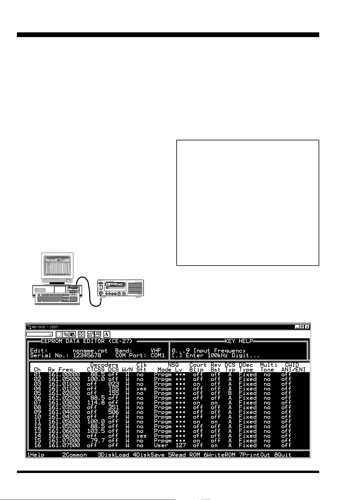
CE27 Programming Software Instruction
With the CE27 Programming Software, you can quickly
and easily program the Vertex Standard VXR-7000
repeater’s channels and configuration from your personal computer. Channel data programming format is
identical for VHF and UHF repeaters. In the event of an
accidental memory failure, repeater memory and configuration data may be re-loaded in a matter of minutes.
The CE27 Programming Software diskette contains the
following files:
• CE27.EXE
• CE27.HLP
Before connecting the VXR-7000 for programming, turn
off both the computer and the VXR-7000. Now connect
the FIF-10A (or FIF-12) + CT-104A USB Programming
Interface to the computer’s USB port and the VXR-7000’s
MIC jack.
Then it will be safe to restart the computer; turning off
the equipment during interconnection avoids the potential for damage to the electronics caused by voltage
spikes.
Insert the distribution diskette into your 3½” drive (after booting DOS), and make a copy of the diskette; use
the distribution diskette for archive purposes, and use
the disk copy for programming.
Place the CE27 (copy) diskette into your 3½” drive (usually “Drive A”), and log onto this drive by typing “A:
[ENTER]”, then load the contents of the CE27 diskette
into a directory named CE27, using the COPY command
(e.g. “COPY A:*.* C:\CE27”).
Now type “CE27 [ENTER]” to start the program. The introductory screen will appear, and you may press any
key to enter the main screen.
Choose the “Help” contents option (F1) from the
program’s Menu for assistance with channel programming or setting of parameters.
Important Note!
Do not run the CE27 programming software di-
rectly from the original distribution diskette.
Copy the programming software to your
computer's hard disk, then run the software
from the hard disk only. Keep the original distribution diskette in a safe place in case you
need to make another copy of it at a later date.
Before creating the programming data for your
VXR-7000 via the CE27 programming software,
upload the current factory hardware environment data from the VXR-7000, using the [F5]
(ReadRom) command. Use this data profile to
create the programming data for this repeater.
VXR-7000 Programming Setup
CE27 Main Screen (Left)
VXR-7000 FM REPEATER OPERATING MANUAL10
Page 15

CE27 Programming Software Instruction
Channel Data Items
Ch: Channel Number
This 2-digit number (01 - 16) is used to identify the channel. Channel numbers occur in sequence, and their order can not be changed.
Rx Freq.: Edit Receive (or simplex) Frequency
Use the [0] - [9] keys to enter the desired channel frequency directly, and press the [ENTER] key.
CTCSS Decoders: Toggle CTCSS Decoder ON/OFF, sets
CTCSS Frequency
Press the [SPACE] bar to
toggle the CTCSS Decoder
“on” or “off,” or press the
[ENTER] key to display the
“TONE SELECT” window,
from which you may select
a CTCSS frequency using the [ARROW] key; press [EN-
TER] again to accept the selected tone, or press [ESC] key
to cancel.
DCS Decoders: Toggle DCS Decoder ON/OFF, sets DCS
Code #
Press the [SPACE] bar to toggle the DCS Decoder ON or
OFF, or press the [ENTER] key to display the “CODE SE-
LECT” window, from which you may select a DCS code
using the [AR-
ROW] key; press
[ENTER] again
to accept the
selected code,
or press the
[ESC] key to
cancel.
W/N: Wide/Narrow Channel Spacing
This function selects the channel spacing environment
in which the VXR-7000 operates.
W (Wide) = 25 kHz Channel Spacing, ±5 kHz De-
viation.
N (Narrow) = 12.5 kHz Channel Spacing, ±2.5 kHz
Deviation.
Press the [SPACE] bar to select the desired channel spacing environment.
Clk Sft: Enable/disable the CPU Clock Shift
This function is only used to move a spurious response
“birdie” should it fall on a current frequency.
Press the [SPACE] bar to toggle “yes” or “no.”
NSQ Mode: Noise Squelch Mode
This command selects the manner of setting of the
Squelch threshold level.
User = The squelch threshold level is fixed via the
“NSQ Lv” parameter (NSQ Lv: 0 [min.] ~
255 [max.]).
Prpgm = The squelch threshold level determined via
the dealer programming.
Press the [SPACE] bar to select the desired NSQ Mode.
NSQ Lv: Noise Squelch threshould level
Use the [0] - [9] keys to enter the desired Squelch threshold level directly, and press the [ENTER] key. Available
values are 0 (min.) ~ 255 (max.).
Court Blip: Courtesy Blip
When this parameter is set to “on,” this function causes
the VXR-7000 to send out a “blip” on the portable/mobile radio is frequency each time the portable radio is
unkeyed. This provides audible confirmation to the user
that the VXR-7000 was able to receive the transmission
from the portable.
Press the [SPACE] bar to toggle “on” or “off.”
CE27 Main Screen (Scrolled Right)
VXR-7000 FM REPEATER OPERATING MANUAL 11
Page 16

CE27 Programming Software Instruction
Rev Bst: Reverse Burst.
When this parameter is set to “on,” the CTCSS tone
signal’s phase is inverted just before the repeater turns
to receive. This allows the portable/mobile station’s
CTCSS Decoder to begin switching off, thus reducing
the transition time required.
Press the [SPACE] bar to toggle “on” or “off.”
DCS Typ: DCS Format
This command is effective only when DCS is chosen for
squelch control.
A = “Normal” DCS
B = “Inverted” (complement) DCS
Press the [SPACE] bar to select the desired DCS Type.
DDec Type: DCS Decoder Type
This command selects the manner in which DCS is to
be decoded.
Fixed = Decodes only the type selected in above pa-
rameter (DCS Typ: Normal or Inverted).
Auto = Both types (Normal and Inverted) will be
decoded.
Press the [SPACE] bar to select the desired DCS Decoder
Mode.
Multi Tone: Enable/disable Multi Tone Operation
Press the [SPACE] bar to toggle Multi Tone Operation
between selections “yes” and “no.”
Press the [ENTER] key
to display the “MULTI
TONE SELECT” win-
dow, from which you
may select a CTCSS
tone or DCS code;
move the cursol to the appropriate field you using the
[ARROW] key, then press the [ENTER] key to open the
“TONE SELECT” or “CODE SELECT” window. Now select
the desired CTCSS tone or DCS code using the [ARROW]
key, then press the [ENTER] key again to accept the selected tone or code, or press the [ESC] key to cancel. You
may set as many as 16 CTCSS tones and/or DCS codes.
Note that, if you do not yet program a CTCSS tone or
DCS code in the “MULTI TONE SELECT” window (when
the “MULTI TONE SELECT” window data is not pro-
grammed), press the [SPAC E] bar to display the “MULTI
TONE SELECT” window directly.
CWID ANI/ENI: Select the Identifier mode
Press the [SPACE] bar to toggle the selections “CW ID,”
“ANI/ENI,” or “Off.” To select this feature to the “CW
ID” or “ANI/ENI,” the “CW ID” parameter must be enabled via the dealer programming.
Action Mode: Select the repeater operation mode
Press the [S
eration or “Simplex” operation.
Tx Freq.: Edit Transmit Frequency
Use the [0] - [9] keys to enter the desired channel frequency directly, and press the [E
CTCSS Encoders: Toggle CTCSS Encoder ON/OFF, sets
CTCSS Frequency
Press the [SPACE] bar to
toggle the CTCSS Encoder
“on” or “off,” or press the
[ENTER] key to display the
“TONE SELECT ” window,
from which you may select
a CTCSS frequency using the [ARROW] key; press [EN-
TER] again to accept the selected tone, or press the [ESC]
key to cancel.
DCS Encoders: Toggle DCS Encoder ON/OFF, sets DCS
Code #
Press the [SPACE] bar to toggle the DCS Encoder “on”
or “off,” or press the [ENTER] key to display the “CODE
SELECT” window, from which you may select a DCS code
using the [AR-
ROW] key; press
[ENTER] again
to accept the
selected code,
or press the
[ESC] key to
cancel.
Base TOT: Enable/disable the Time-Out Timer while in the
“BASE” station mode
Press the [SPACE] bar to toggle the TOT feature selects
“yes” and “no.”
The TOT time is determined via dealer programming.
Base Guard: Enable/disable the Base Guard Feature
When this parameter is set to “yes,” the transmitter will
be inhibited for a few seconds before the repeater (in
the “BASE” station mode) turns to receive.
The inhibit time is determined via dealer programming.
LOUT: Select the Lock Out Feature’s mode
Press the [SPACE] bar to toggle the Lock Out Feature between “BCLO,” “BTLO,” or “off,” then press the [Enter] key to accept the setting. “BCLO” inhibits transmitting while there is carrier present. “BTLO” inhibits
transmitting while there is carrier present unless there
also is a valid tone present.
PACE] bar to toggle between “Duplex” op-
NTER] key.
VXR-7000 FM REPEATER OPERATING MANUAL12
Page 17

CE27 Programming Software Instruction
TX Pwr: Transmitter Power Output Selection
This parameter selects the desired power output from
the VXR-7000 on the current channel. The available values are HIGH and LOW.
Press the [S
TOT Mute: Enable/disable the TOT (Time-Out Timer) beep
monitoring
When this parameter is set to “on,” the alert beep will
sound from the front panel speaker before the repeater
turns itself off.
RptTOT Use: Enable/disable the Time-Out Timer while op-
erating in the repeater mode
Press the [S
“yes” or “no.”
The TOT time is determined via dealer programming.
RptTOT Beep: Enable/disable the TOT beep Transmission
Press the [SPACE] bar to toggle the TOT beep selects
“yes” or “no.”
When this parameter is set to “yes,” the alert beep will
be sent out on the air before the repeater turns itself off,
while oprtating in the “REPEATER” mode.
PACE] bar to select “Hi” or “Lo.”
PACE] bar to toggle the Repeater TOT selects
RPT HT: Enable/disable the Repeater Hang-on Timer
Press the [SPACE] bar to toggle the Repeater Hang-on
Timer selects “yes” or “no.”
When this parameter is set to “yes,” the repeater will
remain keyed for a desired seconds after a receiving
carrier is dropped.
The Hang-up time is determined via dealer programming.
RPT GT: Enable/disable the Repeater Guard
When this parameter is set to “yes,” the transmitter inhibit few second before the repeater is unkeyed.
The inhibit time is determined via dealer programming.
VXR-7000 FM REPEATER OPERATING MANUAL 13
Page 18

Duplexer Installation
Important Notes!
Please refer to the operating manual for your Duplexer for details regarding maximum power input, TX/RX connector locations, etc) before installing the Antenna Duplexer.
Be certain to observe and comply with the specifications for frequency separation and maximum transmitter
power for the duplexer connected to the VXR-7000, particularly when using the VXD-40xx internal duplexer.
When the VXD-40xx is used, the frequency separation must be 5 MHz (minimum) to 10 MHz (maximum), and the
maximum transmitter power output allowed is 40 Watts.
If the VXR-7000 output power (50 Watts) is in excess of the range of the duplexer's capability, you may reduce the
TX output power of the VXR-7000 before installing the Antenna Duplexer, using the following procedure:
1. Connect the VXR-7000’s TX antenna port to a wattmeter and dummy load (the duplexer must not be
connected at this point). Connect any Vertex Standard microphone to the MIC jack, and place the
BASE/REPEATER switch in the “BASE” position.
Select Channel 1 for alignment purposes.
2. Press and hold in the ACCESSORY switch for two
seconds to enter the adjustment mode. The channel
number will begin to blink.
3. Press and hold in the PTT key on the microphone.
The display will indicate “Po” while transmitting.
Observe the power output as indicated on the
watmeter.
4. Keep the holding in the PTT key, press the (UP:
increment) or (DOWN: decrement) button (to the
right of the channel display) repeatedly to adjust
the TX output power to 40 Watts (or less).
5. Keep the holding in the PTT key, press and hold in
the ACCESSORY button for at least two seconds to
save the new setting and exit to the normal operation.
6. Release the PTT key.
7. Repeat steps 2. through 6. (above) for any other
channels (2 through 16) if they are to be used.
8. Re-test each channel in the normal operating mode
to confirm the proper power output. You may now
disconnect all test equipment.
9. The duplexer may now be installed.
The above procedure should only be performed by your
Authorized Vertex Standard Dealer or a qualified radio
technician, in order to ensure accurate calibration. Please
consult with your Authorized Vertex Standard Dealer
for assistance with procurement of a suitable duplexer.
VXR-7000 FM REPEATER OPERATING MANUAL14
Page 19

Installations
Duplexer Installation
1. Remove the 14 screws affixing the top and bottom
covers of repeater, and remove the covers (Figure 1).
2. Turn the repeater upside down.
3. Referring to Figure 2, remove the upper screw in
either side of the front panel, and loosen the lower
screw in either side of the front panel, then slide the
front panel forward slightly.
4. Remove the coaxial cables connected to the TX and
RX antenna jacks of the repeater.
5. Install the duplexer into the compartment on the
bottom side of the repeater, using the four screws
and antenna cable provided in the CT-68 Hardware
Kit (Figure 3). Some duplexers may not line up with
the threaded mounting holes in the repeater's chassis. In this case, use the supplemental mounting
brackets supplied with the CT-68 Hardware Kit (Figure 4).
6. Connect the optional Antenna Cable CT-68 between
the TX antenna jack of the repeater and ANT (center) jack of the duplexer.
7. If your repeater’s Tx/Rx frequency relationship is
“upper shift” type (TXf > RXf), connect the coaxial
cable from the RX Unit to the LOW PASS jack of the
duplexer and connect the coaxial cable from the PA
Unit to the HIGH PASS jack of the duplexer.
If your repeater’s Tx/Rx frequency relationship is
“lower shift” type (TXf < RXf), connect the coaxial
cable from the RX Unit to the HIGH PASS jack of
the duplexer and connect the coaxial cable from the
PA Unit to the LOW PASS jack of the duplexer.
Note: Route the TX coaxial cable from the PA Unit as far
as possible from the RX coaxial cable from the RX Unit.
8. Duplexer installation is now complete. Replace the
front panel back into place, and replace the top and
bottom covers.
Bottom SideTop Side
Figure 1
Bottom Side
Figure 3Figure 2
Figure 4
Bottom Side
VXR-7000 FM REPEATER OPERATING MANUAL 15
Page 20

Specifications
General
Frequency Range: VXR-7000V 136 ~ 150 MHz (A) or 150 ~ 174 MHz (C)
VXR-7000
Number of Channels:16
Channel Spacing: 12.5/25 kHz
Frequency Stability: VXR-7000V ±2.5 ppm
VXR-7000
Antenna Impedance: 50 Ω (N-Type)
Tx Activation System: Carrier-operated, CTCSS tone operated, DCS operated, or remote control
Power Requirements: 115/230 V AC ±10%, 50/60 Hz or 13.8 VDC
Ambient Temperature Range: –30 °C ~ +60 °C
Dimensions (w/o knobs): 325 x 115 x 391.5 mm (12.8 x 4.5 x 15.4 inches)
Weight (approx.): 10 kg (22 lbs.)
Receiver
Receiver Type: Double-conversion Superheterodyne
Sensitivity: VXR-7000V 0.25 µV for 12 dB SINAD, 0.35 µV for 20 dB NQ
VXR-7000U 0.3 µV for 12 dB SINAD, 0.4 µV for 20 dB NQ
Selectivity: 80 dB
Intermodulation: VXR-7000V 80 dB
VXR-7000U 85 dB
Spurious & Image Rejection: VXR-7000V 95 dB
VXR-7000U 85 dB
Audio Output: 4 W @ 4 Ω
U 400 ~ 430 MHz (A), 450 ~ 480 MHz (D), or 480 ~ 512 MHz (F)
U ±1.5 ppm
Transmitter
RF Output: 10 ~ 50 W (Adjustable)
Duty Cycle: 100 %
Maximum Deviation: ±5.0 kHz (25 kHz spacing), ±2.5 kHz (12.5 kHz spacing)
Modulation Type: 16K0F3E/11K0F3E
Audio Distortion: Less than 2.5 % @ 1 kHz
Spurious Emissions: VXR-7000V Better than 80 dB below carrier
VXR-7000U Better than 75 dB below carrier
Specifications are subject to change without notice or obligation.
VXR-7000 FM REPEATER OPERATING MANUAL16
Page 21

Accessories
Supplied
Item Quantity
AC Cord (T9013282) .................................................................................................................................................................... 1
Spare 5A AC Fuse (Q0000005) ................................................................................................................................................... 1
Spare 20A DC Fuse (Q0000079) ................................................................................................................................................. 1
Options
MD-12A8J Desktop Microphone
CT-68 Antenna Cable w/mounting screw (for the Antenna Duplexer)
FIF-10A USB Programming Interface
FIF-12 USB Programming Interface
CT-104A PC Programming Cabel (for FIF-10A and FIF-12)
MR-3 19” Cabinet Rack-Mount Unit
VXR-7000 FM REPEATER OPERATING MANUAL 17
Page 22

WARRANTY POLICY
Vertex Standard warrants, to the original purchaser only, its Vertex Standard manufactured communications products against defects in materials and workmanship under normal use and service for a given period of time from the
date of purchase.
Limited Warranty Details:
North America customers (USA and Canada): http://www.vertexstandard.com/lmr/warranty-terms.aspx
Customers outside of North America: contact the authorized dealer in your country.
VXR-7000 FM REPEATER OPERATING MANUAL18
Page 23

Español
Page 24

Contenidos
Introducción............................................................................................................................ 1
Controles y Conectores ......................................................................................................... 2
Panel Frontal .......................................................................................................................................... 2
Panel Posterior ....................................................................................................................................... 4
Puerto de Conexión para Accesorios.................................................................................. 6
Puerto de Interconexión de LÍNEAS.................................................................................. 8
Instalación ............................................................................................................................... 9
Consideraciones Pertinentes a la Antena ........................................................................................... 9
Selección de Voltaje de la Fuente de CA............................................................................................. 9
Fuente de Alimentación de CC de Reserva ........................................................................................ 9
Emplazamiento del Equipo .................................................................................................................. 9
Modificación del Puente de Conexión para la Red de CA
de la Unidad del Regulador de Conmutación................................. 10
Instrucciones del Programa de Computación CE27 ...................................................... 12
Registro de Dados Relativos a los Canales.......................................................................................13
Instalación del Duplexor .................................................................................................... 16
Especificaciones Técnicas y Accesorios........................................................................... 18
Page 25

Introducción
El VXR-7000 es un repetidor en FM de 50 vatios de calidad comercial, especialmente concebido para proveer un
servicio de comunicación bilateral constante y seguro en una extensa gama de condiciones ambientales.
Proyectado como una estación base de estilo moderno, con componentes de la mejor calidad en todo su sistema, el
VXR-7000 utiliza los modelos computacionales y procesos de fabricación más avanzados que existen hoy en día, de
modo de garantizar el más alto nivel de seguridad funcional para el usuario. La información importante relativa a los
canales de frecuencia queda almacenada en una memoria EEPROM, la cual se puede programar con toda facilidad
valiéndose de un computador personal, un Interfaz USB FIF-10A (o FIF-12) + CT-104A y una Rutina de Programación
CE-27.
Haga el favor de detenerse unos minutos para leer este manual con atención. La información que aquí se presenta le
permitirá aprovechar al máximo todas las ventajas funcionales del VXR-7000. Una vez que termine de leer este manual,
manténgalo a mano para consultarlo en caso de que surja en el futuro cualquier duda relacionada con el manejo de
este aparato.
MANUAL DE INSTRUCCIONES DEL REPETIDOR EN FM VXR-7000 1
Page 26

Controles y Conectores
Panel Frontal
Interruptor de Conexión “POWER”
Éste es el interruptor de conexión principal que
posee el repetidor.
Indicadores LED
“AC”: Este indicador LED se ilumina de color verde
cuando el equipo funciona con CA.
“DC”: Este indicador LED se ilumina de color
amarillo cuando el equipo funciona con CC.
Conector para Micrófono “MIC”
Este conector modular de 8 alfileres de contacto
admite el audio del micrófono y cuenta además con
una línea de control alternativa destinada a activar
el transmisor cada vez que funciona como estación
“BASE”. Dicho conector también viene equipado con
una línea de control de “Conmutación”, aparte de
una línea especial para la “Reproducción de Datos”.
Conmutador para los modos BASE y
del REPETIDOR
Este interruptor le permite alternar entre los modos
del •REPETIDOR• y de transceptor “BASE”. Cuando
se selecciona el modo del “REPETIDOR”, el indicador
LED que se encuentra sobre él se ilumina de color
verde. Al hacer funcionar el equipo como estación
“BASE” (el LED no se enciende), el usuario puede
hablar a través del micrófono y usarlo por
consiguiente como transceptor. Si desea emplear el
VXR-7000 como un repetidor normal, simplemente
coloque el referido interruptor en el modo
correspondiente a “REPETIDOR”.
Conmutador para los modos LOCAL y
REMOTO
Este interruptor le permite alternar entre los modos
de funcionamiento •REMOTO• y “LOCAL”. Cuando se
selecciona el modo “LOCAL”, no se enciende el
indicador LED que está sobre él, haciendo que el
repetidor funcione de acuerdo con los parámetros
de control programados en dicho aparato. Al tener
el modo “REMOTO” habilitado, el LED se ilumina de
color verde, en cuyo caso el repetidor funcionará de
acuerdo con las instrucciones de control que emanen
de un dispositivo externo (conectado en el enchufe
ACC del panel posterior).
Interruptor del MONITOR
Con este interruptor se selecciona el modo de
“Silenciamiento” (o enmudecimiento del receptor).
Cuando el indicador LED sobre él no se enciende,
significa que el silenciamiento mediante “Tono” o
“Código” es el sistema que ha sido activado en el
VXR-7000. Al presionar este interruptor en forma
momentánea, hará que el indicador LED se ilumine
constantemente sobre el panel; en cuyo caso sólo se
habilita el circuito “Reductor de Ruidos”, siendo
posible escuchar toda señal existente en el canal. Si
presiona firmemente este interruptor por más de 1,5
segundos, el LED comenzará a parpadear haciendo
que se abra el circuito de sintonía silenciosa; en este
caso, se escuchará el ruido de fondo al no existir
ninguna señal presente en el canal.
MANUAL DE INSTRUCCIONES DEL REPETIDOR EN FM VXR-70002
Page 27

Controles y Conectores
Interruptor para ACCESORIOS
Este interruptor se puede programar para
aplicaciones especiales, tales como la selección de
potencia entre los niveles Alto y Bajo, según lo
disponga el distribuidor Vertex Standard de su
localidad. El indicador LED sobre dicho interruptor
se ilumina de color verde cuando esta función ha
sido habilitada. Para mayores detalles sobre el tema,
comuníquese con el representante Vertex Standard
de su localidad.
Perilla de VOLumen
Con este control se regula el nivel de volumen que
emana del parlante ubicado en el panel frontal. Si
lo desea, usted puede ajustar esta perilla en la
máxima regulación de la izquierda cuando no se
requiera monitorear repetidores.
Perilla de Silenciamiento “SQL”
Mediante esta perilla de control se selecciona el nivel
umbral de silenciamiento de ruido.
Botones Selectores de Canales ( y )
Oprima cualquiera de estos dos botones para
seleccionar el canal de comunicación que desea
utilizar.
Indicador de Canales
Este indicador LED de siete segmentos exhibe el
número correspondiente al canal de comunicación
vigente.
Despliegue del Sistema Automático de
Identificación Numérica “ANI”
El Visualizador de Cristal Líquido (LCD) del
Sistema Automático de Identificación Numérica
exhibe el mensaje ANI que se programa conforme
al código de identificación recibido.
Indicador de Transmisión y
Ocupación “TX/BUSY”
El indicador “BUSY” se ilumina de color verde una
vez que se ocupa el canal, en tanto que el icono de
“TX” se ilumina de color rojo mientras se encuentre
transmitiendo el repetidor.
Botón de REPOSICIÓN del Sistema ANI
(1) ANI
Oprima este botón para borrar el mensaje
contenido en el visualizador del Sistema
Automático de Identificación Numérica y
apagar la luz de fondo de la pantalla de LCD.
(2) ENI
Oprima este 2 botón para desconectar el tono
de Alerta.
Oprima este botón una vez más para borrar el
mensaje contenido en el visualizador del
Sistema Automático de Identificación Numérica
y apagar la luz de fondo de la pantalla de LCD.
MANUAL DE INSTRUCCIONES DEL REPETIDOR EN FM VXR-7000 3
Page 28

Controles y Conectores
Panel Posterior
Enchufe para parlante externo “EXT SP”
Este minienchufe de 3,5 mm y dos alfileres de
contacto suministra la salida de audio variable para
un parlante externo. La impedancia de audio en este
enchufe es de 4 ~ 16 ohmios, cuyo nivel varía
conforme a la regulación de la perilla de VOLumen
ubicada en el panel frontal del equipo.
Enchufe para Antena de TX
Este enchufe coaxil tipo N proporciona la señal de
salida de transmisión para instalar una antena
emisora o acoplar la clavija de TX de un duplexor,
de haber instalado uno. La impedancia de salida que
se requiere es de 50 Ω.
Enchufe para Antena de RX
Este enchufe coaxil tipo N proporciona la señal de
entrada de recepción para instalar una antena
receptora o acoplar la clavija de RX de un duplexor,
de haber instalado uno. La impedancia de entrada
que se requiere es de 50 Ω.
Enchufe para accesorios “ACC”
Este conector DB-25 es el punto de interconexión
entre el microprocesador del VXR-7000 y los
dispositivos periféricos (como una Unidad de
Troncalización “VX-TRUNK” por ejemplo).
Terminal a Tierra “GND”
Para conseguir un óptimo rendimiento y seguridad
funcional, este terminal debe estar conectado a una
buena toma de tierra con un cable trenzado, corto y
de grueso calibre.
Enchufe para Alterna
Este receptáculo admite el cordón de alimentación
de alterna, el cual debe conectarlo a la red de CA o
bien, directamente en el enchufe de la pared.
Terminal para Batería “BATT”
Estos bornes admiten entre 12 y 15 voltios de CC de
modo que el repetidor funcione con una batería u
otra fuente de alimentación de CC que pueda poseer
el usuario. Cuando el VXR-7000 se hace funcionar a
partir de la red de CA, una pequeña corriente de
carga se hace presente en estos terminales, con el
objeto de conservar la energía existente en dicha
batería. Se recomienda emplear pilas con una
potencia nominal de 12 voltios, 55 Ah (como
mínimo) para realizar transmisiones breves de
emergencia o de apoyo.
Conector de LÍNEA
Este enchufe modular de 8 alfileres de contacto se
usa para accionar el mecanismo de control remoto
y cuenta además con una salida para el audio de TX
y RX, la activación del transmisor y para dar a
conocer el estado actual del circuito de
silenciamiento. La impedancia del audio de TX y
RX es de 600 Ω.
MANUAL DE INSTRUCCIONES DEL REPETIDOR EN FM VXR-70004
Page 29

Controles y Conectores
Nota
MANUAL DE INSTRUCCIONES DEL REPETIDOR EN FM VXR-7000 5
Page 30

Puerto de Conexión para Accesorios
El repetidor VXR-7000 viene equipado con un conector
hembra DB 25F de 25 alfileres de contacto destinado a
la conexión de dispositivos accesorios. Use un conector
macho DB-25M de 25 alfileres de contacto cuando desee
acoplar dispositivos a dicho repetidor. A continuación
se presenta una descripción detallada de cada uno de
los alfileres existentes en el referido conector:
Alfiler 1: “GND”
Conexión a masa para todos los niveles lógicos,
incluyendo el retorno de la fuente de alimentación.
Alfiler 2: +13.8 V [Fuente de Alimentación]
Esta espiga suministra corriente continua regulada
de 13,8 voltios y 1.0 A que genera la fuente del
repetidor. Instale un fusible de 1 A en la línea de CC
del dispositivo externo con el objeto de proteger el
repetidor.
Alfiler 3: “TX AF IN” [Entrada del Transmisor
Analógico]
(Banda Vocal: 300 ~ 3.000 Hz)
La impedancia de entrada es de aproximadamente
600 Ω. Este audio es inyectado antes de llegar a la
etapa de filtro contra radiaciones espurias, a fin de
limitar los niveles excesivos de la señal de entrada.
Utilice un cable blindado para acoplar este alfiler y
conectar la sección apantallada a tierra (GND).
Alfiler 4: “TONE IN” [Entrada del Transmisor]
(Banda Subaudible: 6 ~ 250 Hz)
La impedancia de entrada es elevada
(aproximadamente 22 k Ω). Al inyectar en este punto
una tensión demasiado alta produce la desviación
excesiva de señales DCS o CTCSS, degradando la
calidad funcional del equipo. Utilice un cable
blindado para acoplar este alfiler y conectar la
sección apantallada a tierra (GND).
Alfiler 5: N.C.
(No existe ninguna conexión en este punto)
Alfiler 6:“DISC OUT” [Salida Analógica]
(Banda Ancha: 0 ~ 3.000 Hz)
Las señales que se reciben con una desviación
estándar producen un audio de aproximadamente
1 Vp-p en este alfiler. La impedancia de salida es de
aproximadamente 600 Ω, la cual es extraída antes
del circuito de silenciamiento y desacentuación.
Utilice un cable blindado para acoplar este alfiler y
conectar la sección apantallada a tierra (GND).
Alfiler 8:“RSSI” [Salida Analógica]
Este alfiler suministra una tensión de CC
proporcional a la fuerza de la señal que se está
recibiendo en ese momento (Indicador de Intensidad
de la Señal de Recepción). Esta baja salida de
impedancia es producida por el subsistema de FI y
separada por un amplificador de operación interno.
A continuación se incluye la representación gráfica
de los voltajes más comunes:
Alfiler 9: “COAX. SW” [Salida Lógica]
(de Poca Actividad)
La función de dicho alfiler es la de ejercer control
sobre un relé de conmutación externo. Es una salida
de colector abierto que puede descender alrededor
de 10 mA cuando está activada. Esta señal se cambia sólo si el repetidor se encuentra programado en
el modo “SÍMPLEX”. Si decide programar el
repetidor en el modo “DÚPLEX”, entonces la señal
permanece abierta constantemente (manteniendo
una impedancia elevada).
Alfiler 10: N.C.
(No existe ninguna conexión en este punto)
Alfiler 11: “NSQ DET”
Es una salida de baja actividad de colector abierto
capaz de descender alrededor de 10 mA, la cual sirve
para indicar que el circuito de silenciamiento del
receptor está abierto. Cuando el control de
silenciamiento ha sido ajustado en la forma debida,
dicha salida revela la presencia de una portadora
en el canal de recepción.
Alfiler 7:“GND”
Conexión a masa para todos los niveles lógicos,
incluyendo el retorno de la fuente de alimentación.
MANUAL DE INSTRUCCIONES DEL REPETIDOR EN FM VXR-70006
ACC Jack
DB-25 Pin Numbering
Page 31

Puerto de Conexión para Accesorios
Alfiler 12: “EXT PTT”
Esta entrada es excitada internamente hasta alcanzar
un máximo de 5 V CC. Cuando un dispositivo
externo la hace descender, se activa el transmisor
del repetidor mientras dicho aparato se encuentre
funcionando a partir del modo de “BASE”. Evite
suministrar tensiones que superen los 5 V en este
alfiler, puesto que de lo contrario podría dañar el
interior del microprocesador dentro de la Unidad
de CONTROL del VXR-7000.
Alfiler 13: “GND”
Conexión a masa para todos los niveles lógicos,
incluyendo el retorno de la fuente de alimentación.
Alfiler 14: “GND”
Conexión a masa para todos los niveles lógicos,
incluyendo el retorno de la fuente de alimentación.
Alfiler 15: N.C.
(No existe ninguna conexión en este punto)
Alfileres 16, 17, 18, y19: “REMOTE CH DATA”
[Entradas Lógicas D3, D2, D1 y D0] (De Poca Actividad)
Estas entradas son excitadas internamente hasta
alcanzar un máximo de 5-V CC. Cuando un
dispositivo externo las hace descender, éstas
seleccionan uno de los 16 canales de comunicación
previamente programados en el equipo. La tabla de
verdades lógicas que se incluye a continuación
muestra las combinaciones para seleccionar los 16
canales existentes.
En la tabla de verdades lógicas el “1” representa la
ausencia de conexión y el “0”, una toma a masa en
el alfiler.
La lógica en la selección de canales no se inhibe al
activar el transmisor: el repetidor va a cambiar de
frecuencia cuando se le instruya, aunque en ese
momento se encuentre transmitiendo.
Evite suministrar tensiones que superen los 5 V en
estos alfileres, puesto que de lo contrario podría
dañar el interior del microprocesador dentro de la
Unidad de CONTROL del VXR-7000.
Canal
1
2
3
4
5
6
7
8
9
10
11
12
13
14
15
16
Alfiler 16
(D3)
1
1
1
1
1
1
1
1
0
0
0
0
0
0
0
0
Alfiler 17
(D2)
Alfiler 18
(D1)
1
1
1
1
0
0
0
0
1
1
1
1
0
0
0
0
1
1
0
0
1
1
0
0
1
1
0
0
1
1
0
0
Alfiler 19
(D0)
1
0
1
0
1
0
1
0
1
0
1
0
1
0
1
0
Alfiler 20: “GND”
Conexión a masa para todos los niveles lógicos,
incluyendo el retorno de la fuente de alimentación.
Alfiler 21: “A-OUTPUT” [Salida Lógica]
(De Baja Actividad)
Esta salida lógica de colector abierto y de baja
actividad experimenta una disminución de voltaje
al accionar la tecla para ACCESORIOS del panel frontal. Ésta puede descender alrededor de 10 mA en el
momento de ser activada por el operador.
Alfiler 22: “RXD LOW”
[Salida Digital para Transmisión de DATOS]
(300 ~ 3.000 Hz)
Este alfiler es una salida para señales de recepción
de datos a velocidad reducida, en la que la
información es extractada una vez que haya
atravesado las etapas de desacentuación y del filtro
pasabajos.
Alfiler 23: “RXD HI”
[Salida Digital para Transmisión de DATOS]
Este alfiler es una salida para señales de recepción
de datos a gran velocidad, en la que la información
es extractada inmediatamente después de atravesar
el circuito discriminador, antes de cualquier etapa
de desacentuación.
Alfiler 24: “TXD LOW”
[Entrada Digital para Transmisión de DATOS]
(300 ~ 3.000 Hz)
Este alfiler funciona como una entrada de señales
de información digital a velocidad reducida hacia
el repetidor. Las referidas señales son inyectadas antes de la etapa limitadora y de desacenctuación, a
fin de recortar los niveles excesivos de la señal de
entrada.
Alfiler 25: “TXD HI”
[Entrada Digital para Transmisión de DATOS]
Este alfiler funciona como una entrada de señales
de información digital a gran velocidad hacia el
repetidor. Las referidas señales son inyectadas una
vez atravesada la etapa del filtro contra radiaciones
espurias que posee el transmisor.
MANUAL DE INSTRUCCIONES DEL REPETIDOR EN FM VXR-7000 7
Page 32

Puerto de Interconexión de LÍNEAS
El VXR-7000 viene equipado con un enchufe modular
de 8 alfileres de contacto para las aplicaciones
relacionadas con la interconexión de líneas. Se debe
insertar una clavija modular tipo Western Electric® RJ45
en el referido enchufe. El diagrama de interconexiones
externas se incluye más adelante en el manual.
Cabe hacer notar que existen dos tipos de enchufes
modulares, de 4 y 8 líneas. Si se utiliza un enchufe modular de 4, sólo se deben realizar las conexiones de las
líneas de ENTRADA y SALIDA. Es necesario emplear uno
de 8 para tener acceso a la totalidad de las líneas.
Conforme a la interface de telecomunicación estándar,
las conexiones de línea en el conector interfacial
correspondiente presentan una impedancia balanceada,
las cuales se describen de la siguiente manera.
Alfileres 1 y 2: [RX SQ(+), RX SQ(–)]
El VXR-7000 trae incorporado un seccionador óptico
para facilitar la señalización E (EAR). Dicho
seccionador óptico interviene cuando se presenta en
el canal una señal que sobrepasa el umbral de
silenciamiento del receptor (con el tono CTCSS o
código DCS correspondiente, de haber sido
habilitada esa función). El alfiler identificado como
RX SQ(–) es el emisor y el RX SQ(+), el colector.
Alfileres 5 y 6:
[LINE OUT (Audio de la Línea de Recepción)]
El audio de recepción se obtiene a través de este par,
el cual está supeditado a la decodificación CTCSS o
DCS si la intensidad de la señal recibida sobrepasa
el umbral de silenciamiento establecido en el
aparato.
De acuerdo a la configuración original del equipo,
una señal de recepción de 1- kHz con una desviación
estándar genera -10 dBm en la línea; sin embargo,
es posible alterar este valor mediante el VR4002 y
el S4001 (en la Unidad de CONTROL del repetidor).
Alfileres 7 y 8: [TX KEY(+), TX KEY(–)]
El VXR-7000 trae incorporado un seccionador óptico
para facilitar la señalización M (MIC). Es decir, al
suministrar una tensión a estos alfileres se produce
la conexión del seccionador y se activa al mismo
tiempo el transmisor. El alfiler TX KEY(+)
corresponde al ánodo del seccionador, mientras que
RX SQ(–) al cátodo del mismo.
Alfileres 3 y 4:
[LINE IN (Audio de la Línea de Transmisión)]
Las señales analógicas entre 300 y 3000 Hz
suministradas a este par son aplicadas al transmisor
cuando el repetidor ha sido programado en el modo
de “BASE” (el indicador LED del REPETIDOR
permanece apagado) y es activado ya sea por la señal
de entrada “TX KEY” (refiérase a la sección
siguiente) o bien, mediante la señal “EXT PTT”
generada en alfiler de contacto 12 ubicado en la
clavija ACC del panel posterior. La desviación
estándar se logra con un nivel de línea de –10dBm.
Clavija de Interconexión de LÍNEAS
Numeración de los Alfileres de la Clavija Modular
MANUAL DE INSTRUCCIONES DEL REPETIDOR EN FM VXR-70008
Page 33

Instalación
Consideraciones Pertinentes a la Antena
El funcionamiento del repetidor sin un duplexor
requiere que se instalen dos antenas, una para recibir y
otra para emitir, de modo de evitar que la antena de
recepción absorba energía proveniente de la de
transmisión. Existen varias formas de realizar esta
instalación, dependiendo de la separación existente entre las frecuencias de Tx y Rx, y de los lugares donde es
posible montar dicha antena. De incluir un duplexor, es
suficiente instalar una sola antena tanto para recibir
como para transmitir. En caso de contar con un duplexor
de tamaño reducido, se recomienda emplear un modelo
de seis cavidades (como mínimo). Vertex Standard
aconseja instalar un duplexor, pero si de todas formas
desea obtener mayores detalles sobre el tema,
comuníquese con el distribuidor autorizado de su
localidad.
Independientemente de la selección que realice, es de
suma importancia que monte la o las antenas en el punto
más elevado y despejado posible, de preferencia dentro
de la trayectoria óptica de todos los usuarios del
repetidor. Además, es necesario minimizar las pérdidas
en la(s) línea(s) de alimentación y por este motivo, se
deben emplear cables de buena calidad y que sean lo
más corto posible. No obstante, de requerir líneas de
alimentación más largas, utilice un cable coaxil de “enlace físico” para aminorar tales pérdidas en las líneas.
Las antenas de repetidores deben presentar una
impedancia de 50 Ω en la frecuencia de trabajo vigente.
Cuando se usan antenas de emisión y recepción
independientes, aquéllas de banda angosta con un alto
factor Q pueden servir para disminuir la interacción.
No obstante, cuando se instala una sola antena con un
duplexor, tiene que usar una de banda ancha con un
bajo factor Q.
Modificar la tensión de alterna primaria también
requiere reemplazar el fusible de la Unidad de FILTRO
si cambia el voltaje de 100 V CA (100 ~ 127 V CA) a 200
V CA, o viceversa. Use un fusible de 5 amperes para
100 V de CA o si no, uno de 3 amperes para 200 V CA.
Fuente de Alimentación de CC de Reserva
Para hacer funcionar el repetidor ininterrumpidamente
durante cortes de electricidad, usted puede conectar una
batería recargable de 12 voltios (se recomienda una de
55 Ah o más) en el terminal “BATT” ubicado el panel
posterior del VXR-7000. Mientras el repetidor esté
funcionando a partir de una fuente de alterna, una
pequeña corriente de carga mantiene la batería
debidamente cargada. En caso de que se produjera un
corte de electricidad, el circuito de control de potencia
automático hará pasar instantáneamente el repetidor a
la batería de reserva, evitando de este modo interrumpir
el funcionamiento de dicho aparato.
Después de operar el equipo con la batería de reserva
por un período de tiempo prolongado, usted debe
desconectarla del VXR-7000 y recargarla separadamente
antes de instalarla de nuevo, puesto que la carga de
compensación no es suficiente para restituir la energía
de una batería agotada por completo.
Jamás vuelva a aplicar al VXR-7000 energía eléctrica de
CA teniendo una batería descargada conectada a dicho
aparato, puesto que la corriente continua de arranque
podría inutilizar tanto al repetidor como a la fuente de
alimentación complementaria.
Cuando el repetidor funciona a partir de una batería o
una fuente de alimentación de CC, necesita contar con
aproximadamente 7 amperes a 12 voltios durante la
transmisión.
JAMÁS TRANSMITA SIN TENER UNA
ANTENA DE TRANSMISIÓN CONECTADA EN
LA CLAVIJA CORRESPONDIENTE DEL
REPETIDOR.
Selección de Voltaje de la Fuente de CA
Cada repetidor viene configurado para admitir una
determinada tensión de la red de CA entre 100 y 253 V
CA. Tal especificación aparece indicada en una etiqueta
cerca de la clavija de CA en el panel posterior del
aparato. De no encontrar ninguna etiqueta o si la tensión
alterna especificada no coincidiera con la de la línea local, revise la configuración de los cables dentro de la
Unidad Reguladora de Conmutación del repetidor y
proceda a cambiar las conexiones (y la etiqueta), si fuera
necesario, de la forma que se señala en la próxima página
del manual.
A pesar de que el margen de temperaturas de
funcionamiento del repetidor es bastante amplia, la
mejor ubicación es la que presenta una temperatura
ambiente no muy cercana a ninguno de los extremos de
la gama especificada y en donde además no existan
variaciones fortuitas. Asegúrese de que el aire circule
libremente y en forma constante alrededor del disipador
térmico en la placa posterior del aparato. En aquellos
lugares de clima cálido, no se debe instalar el repetidor
en un cuarto pequeño y carente de ventilación.
Proteja el repetidor del viento y la lluvia, al igual que
de las temperaturas o niveles de humedad extremos que
puedan acortar la vida útil del equipo. Si es posible, procure emplazar el repetidor en un lugar que también sea
asequible para el personal encargado del
mantenimiento.
MANUAL DE INSTRUCCIONES DEL REPETIDOR EN FM VXR-7000 9
Emplazamiento del Equipo
Page 34

Instalación
Modificación del Puente de Conexión para la Red de
CA de la Unidad del Regulador de Conmutación
Antes de intentar modificar este puente de conexión,
retire el cordón tomacorriente de la clavija de CA
ubicada en el panel posterior del aparato.
Tomando la ilustración 1 como referencia, saque los
14 tornillos que sujetan las cubiertas superior e inferior del repetidor y retírelas del aparato.
Saque los ocho tornillos que sostienen la cubierta del
blindaje para la Unidad del FILTRO y retírela
posteriormente del equipo (refiérase a la Ilustración 1).
Después de desconectar todos los alambres y
conectores de la Unidad de FILTRO, saque los seis
tornillos que sujetan la Unidad del Regulador de
Conmutación y retírela del equipo (la Unidad
Reguladora de Conmutación viene montada junto
con la Unidad de FILTRO: Ilustración 2).
Tomando ahora la Ilustración 3 como referencia,
saque los cuatro tornillos y remueva el disipador
térmico de la Unidad del Regulador de
Conmutación.
Posteriormente, refiérase a la Ilustración 4 y realice
la distribución correcta de los cables del puente de
conexión en la Unidad del Regulador de
Conmutación para el voltaje de la red de CA que se
utiliza en su localidad (100-127 V CA ó 207-253 V
CA).
Vuelva a colocar el disipador térmico en la Unidad
del Regulador de Conmutación, reinstale a
continuación la referida unidad en el chasis del
aparato y termine por enlazar todos los alambres y
conectores en la unidad de FILTRO del aparato.
Cambie el fusible de CA (FH6001) en la Unidad de
Filtro de acuerdo con la gama de tensiones de la
red:
100 V CA (100-127 V CA): 5 A
200 V CA (207-253 V CA): 3A
Finalmente vuelva a colocar la cubierta del blindaje
al igual que las tapas superior e inferior del equipo.
Con esto se da por concluido el proceso de
redistribución de los cables en el sistema.
¡Importante!: Si desea modificar la gama de tensiones
de CA, debe reemplazar también el fusible en la Unidad
de FILTRO. No cambie ese fusible por uno de fusión
lenta.
Unidad de FILTRO
B
A
C
B
C
Unidad del Regulador
de Conmutación
Ilustración 2
Ilustración 1
A
MANUAL DE INSTRUCCIONES DEL REPETIDOR EN FM VXR-700010
Page 35

Ilustración 4
Instalación
100~ 127 V CA
207 ~ 253 V CA
Unidad del Regulador
de Conmutación
Ilustración 3
MANUAL DE INSTRUCCIONES DEL REPETIDOR EN FM VXR-7000 11
Page 36

Instrucciones del Programa de Computación CE27
Con el Programa de Computación CE27 el usuario
puede configurar en forma rápida y efectiva los canales
al igual que las diferentes funciones del repetidor Vertex Standard VXR-7000 con la ayuda de un computador
personal. En caso de una pérdida accidental de memoria, es posible volver a introducir los datos relativos a la
configuración y a los registros del repetidor en un par
de minutos.
El diskette del Programa de Computación CE27 contiene
los siguientes archivos:
• CE27.EXE
• CE27.HLP
Antes de conectar el VXR-7000 y realizar la
programación, apague el computador al igual que el
referido repetidor. A continuación, proceda a insertar el
Interfaz FIF-10A (o FIF-12) + CT-104A en el puerto USB
del computador y el conector MIC del repetidor,
respectivamente.
En ese entonces es posible reiniciar el computador sin
ningún peligro; el hecho de apagar el equipo durante la
interconexión evita que se dañen los componentes
electrónicos por causa de puntas de tensión.
Instalación del Programa en el VXR-7000
Inserte el diskette de distribución en la unidad de disco
de 3-1/2” (después de haber cargado el sistema DOS en
la memoria) y haga una copia del mismo; conserve el
diskette de distribución como archivo y use la copia para
llevar a cabo la programación.
Inserte el diskette CE27 (copia) en la unidad de 3-1/2”
(generalmente la “Unidad de Disco A”) y marque “A
[INGRESAR]” para iniciar el registro en la referida ranura
y cargar por consiguiente los contenidos del diskette en
el directorio denominado CE27, utilizando la señal de
mando de “DUPLICACIÓN” (es decir, “COPY A:*.*
C:\CE27”).
En esta etapa marque “CE27 [INGRESAR]” con el teclado
para dar inicio al programa. Cuando aparezca la
pantalla introductoria, oprima cualquiera de las teclas
a fin de ingresar a la pantalla principal.
Cuando necesite orientación para configurar los canales
o definir los parámetros del repetidor, seleccione la
opción “Help” [Ayuda] en el Menú del programa.
¡Nota Importante!!
No intente empezar el software CE27
directamente del disquete original. Haga
una copia del programa al disco duro de su
computadora, y empiece el programa desde
alli. Mantenga el disquete original en un
lugar seguro en el caso que tenga que hacer
otra copia en el futuro.
Antes de programar el VXR-7000, via la
programacion CE27, lea la informacion del
repetidor primero utilizando la tecla [F5]
[ReadRom]. Utilice estos parametros para
programar este repetidor.
Pantalla Principal del CE-27 (Izquierda)
MANUAL DE INSTRUCCIONES DEL REPETIDOR EN FM VXR-700012
Page 37

Instrucciones del Programa de Computación CE27
Registro de Datos Relativos a los Canales
Ch: Número de Canal
Este número de 2 dígitos (01 - 16) se utiliza para
identificar el canal. Los números de canales se
suceden en el orden normal y en este caso no es
posible alterar la disposición de los mismos.
Rx Freq.: Edición de la Frecuencia de Recepción (o símplex)
Utilice las teclas del [0] al [9] para registrar
directamente la frecuencia del canal de tráfico que
desea utilizar y oprima [INGRESAR] a continuación
con el objeto de concluir este paso.
Decodificadores CTCSS: Alterna entre los estados de
Conexión y Desconexión del Decodificador CTCSS, define la
Frecuencia CTCSS en el repetidor
Oprima la barra [ESPACIADORA] para alternar entre
los estados de Conexión y Desconexión del
Decodificador CTCSS o si prefiere, presione
[INGRESAR] a fin de exhibir la ventana de ”SELECCIÓN
DE
TONOS,” la cual le
permite escoger una
de las frecuencias
CTCSS con la [FLECHA]
del teclado; vuelva a
oprimir [INGRESAR] una
vez más para aceptar el tono seleccionado o en su
defecto, accione [ESC] para cancelar esta operación.
Decodificadores DCS: Alterna entre los estados de
Conexión y Desconexión del Decodificador DCS, define el #
de Código DCS en el repetidor
Oprima la barra [ESPACIADORA] para alternar entre
los estados de Conexión y Desconexión del
Decodificador DCS o si prefiere, presione [INGRESAR]
a fin de exhibir la ventana de ”SELECCIÓN DE CÓDIGOS”
en la pantalla, a partir de la cual es posible escoger
uno de los
códigos
DCS con la
[ F LECHA]
del teclado.
Finalmente
presione
[INGRESAR] una vez más para aceptar el código
seleccionado o en su defecto, accione la tecla [ESC]
para cancelar esta operación.
W/N: Espaciamiento Amplio y Angosto de Canales
Mediante esta función es posible seleccionar el
espaciamiento entre canales en el que el VXR-7000
puede operar.
W (Ancho) = Espaciamiento de Canales de 25
kHz, Desviación de ±5 kHz.
N (Angosto) = Espaciamiento de Canales de
12.5 kHz, Desviación de ±2.5
kHz.
Oprima la barra [ESPACIADORA] para seleccionar el
espaciamiento entre canales que desea utilizar.
CE-27 Main Screen (Scrolled Right)
MANUAL DE INSTRUCCIONES DEL REPETIDOR EN FM VXR-7000 13
Page 38

CE27 Programming Software Instruction
Clk Sft: Habilita e Inhabilita la Conmutación del Reloj de la
Unidad de Procesamiento Central o “CPU”.
Esta función se usa solamente para desplazar el
“silbido” de una respuesta espuria en caso de que
éste cayera en la frecuencia de trabajo deseada.
Modo “NSQ”: Modo de Silenciamiento por Ruido
Este modo de ajuste de mando define el nivel umbral para el Circuito de Silenciamiento del repetidor.
User (Fijo) = El nivel umbral del circuito
reductor de ruidos se define
mediante un parámetro
programable del menú (NSQ
Lv: 0 [mín.] ~ 255 [máx.]).
Prpgm (Libre) = EL nivel umbral del referido
circuito se puede ajustar
temporalmente con la perilla
SQL ubicada en el panel fron-
tal del aparato.
Oprima finalmente la barra [ESPACIADORA] con el
objeto de seleccionar el modo “NSQ” que desea
emplear.
NSQ LV: Nivel Umbral de Silenciamiento por Ruido
Emplee las teclas del [0] al [9] para registrar
directamente el nivel umbral en el circuito reductor
de ruidos y oprima [INGRESAR] a continuación. Éste
es un valor de ajuste arbitrario, el cual debe ser
programado en forma experimental. Los valores que
el usuario tiene a su disposición van de 0 (mín.) a
255 (como máximo).
Court Blip: “Blip” de Cortesía
Cuando dicho parámetro se encuentra habilitado,
esta función hace que el VXR-7000 genere un “blip”
en la frecuencia del radio portátil cada vez que no
se manipule dicho aparato. Lo anterior constituye
una confirmación audible de que el VXR-7000 fue
capaz de recibir la transmisión proveniente del
aparato portátil.
Rev Bst: Ráfaga Inversa
Cuando este parámetro se encuentra “habilitado”,
se invierte la fase de la señal de tono CTCSS justo
antes de que el repetidor se cambie para recibir. Esto
permite que el Decodificador CTCSS de la estación
portátil o móvil inicie la apertura del circuito,
reduciendo de este modo el tiempo de transición
que se requiere para este fin.
DCS Typ: Formato DCS
Esta señal de mando es efectiva sólo cuando el
Sistema por Código Digital “DCS” ha sido escogido
para controlar el mecanismo de silenciamiento en
el equipo.
A = DCS “Normal”
B = DCS “Inverso” (complemento)
Oprima la barra [ESPACIADORA] con el objeto de
seleccionar el Tipo de decodificación DCS que desea
emplear.
DDec Type: Tipo de Decodificación DCS
Esta señal de mando se utiliza para escoger la forma
en que el Silenciamiento por Código Digital ha de
ser decodificado.
Fixed (Fijo) = Decodifica el tipo
seleccionado en el
parámetro anterior
(“DCS Typ”: Normal o
Inverso).
Auto (Automático) = Decodifica ambos tipos
(Normal e Inverso).
Oprima la barra [ESPACIADORA]con el propósito de
seleccionar el Modo de Decodificación DCS que
desea emplear.
Multi Tone: Habilita e Inhabilita la Selección Múltiple de Tonos
Oprima la barra [ESPACIADORA] para Habilitar e
Inhabilitar la referida función o si prefiere, oprima
[INGRESAR] con el objeto de desplegar la ventana de
“SELECCIÓN MÚLTIPLE DE TONOS,” a partir de la cual es
posible escoger
con la [FLECHA] del
teclado un tono
CTCSS o uno de
los códigos DCS
disponibles en el
sistema. Finalmente presione [INGRESAR] una vez más
para aceptar el código seleccionado o si no, oprima
la tecla [ESC] para cancelar esta operación.
CWID ANI/ENI: Selección del modo de Identificación
Oprima la barra [ESPACIADORA] para alternar entre el
Identificador en Morse “CW ID”, la función “ANI/
ENI” o la Desconexión (OFF) de ambos modos. La
función “ANI/ENI” y el Identificador en Morse deben
ser programados por el distribuidor.
Modo de Accionamiento: Selecciona el modo de operación
del repetidor
Presione la barra [ESPACIADORA] con el objeto de
alternar entre el modo Símplex y Dúplex en el
repetidor.
Tx Freq.: Edición de la Frecuencia de Transmisión
Utilice las teclas del [0] al [9] para registrar
directamente la frecuencia del canal de tráfico que
desea y oprima [INGRESAR] a continuación con el
objeto de concluir este paso.
MANUAL DE INSTRUCCIONES DEL REPETIDOR EN FM VXR-700014
Page 39

CE27 Programming Software Instruction
Codificadores CTCSS: Alterna entre los estados de
Conexión y Desconexión del Codificador DCS, define la
frecuencia CTCSS del repetidor
Oprima la barra [ESPACIADORA] para alternar entre
los estados de Conexión y Desconexión del
Codificador CTCSS o si prefiere, presione [INGRESAR]
a fin de exhibir la ventana de ”SELECCIÓN DE TONOS”
en la pantalla, a partir
de la cual es posible
escoger con la [FLECHA]
del teclado cualquiera
de los tonos CTCSS
disponibles en el
sistema. Finalmente presione [INGRESAR] una vez más
para aceptar el tono seleccionado o en su defecto,
accione la tecla [ESC] para cancelar esta operación.
Codificadores DCS: Alterna entre los estados de Conexión
y Desconexión del Codificador DCS, define el # de Código
DCS en el repetidor
Oprima la barra [ESPACIADORA] para alternar entre
los estados de Conexión y Desconexión del
Codificador DCS o si prefiere, presione [INGRESAR] a
fin de exhibir la ventana de ”SELECCIÓN DE CÓDIGOS”
en la pantalla, a partir
de la cual es posible
escoger con la [FLECHA]
del teclado cualquiera
de los códigos DCS
disponibles en el sistema. Finalmente presione
[INGRESAR ] una vez más para aceptar el código
seleccionado o en su defecto, accione la tecla [ESC]
para cancelar esta operación.
Base TOT: Habilita e Inhabilita el Temporizador de Intervalos
de Transmisión al funcionar como estación “BASE”
Oprima la barra [ESPACIADORA] con el objeto de
alternar entre la Conexión y Desconexión del
Temporizador de Intervalos de Transmisión cuando
funciona como estación Base.
El intervalo del temporizador se define mediante la
programación que realiza el distribuidor.
Vigilancia Base: Habilita e Inhabilita el mecanismo de
Vigilancia en el modo de Base
Cuando este parámetro se encuentra habilitado, el
transmisor se inhibe por un par de segundos antes
de que el repetidor se cambie para recibir (al
funcionar como estación “BASE”).
El tiempo de inhibición se define mediante la
programación que realiza el distribuidor.
LOUT: Selección de la Función de Bloqueo para Canal
Ocupado
Oprima la barra [ESPACIADORA] con el objeto de
alternar la Función de Bloqueo entre los modos
“BCLO,” “BTLO” o la desconexión (“off”) de am-
bos. En el modo “BCLO” se inhiben las
transmisiones mientras exista una portadora
presente. En el modo “BTLO” se inhiben las
transmisiones mientras exista una portadora
presente, pero con la condición de que haya también
un tono válido; lo anterior le permite al operador
responder a una estación controlada mediante tono
al mismo tiempo que mantiene el control de
“Bloqueo” con respecto a las señales que no son
controladas mediante tono.
TX Pwr: Selección de la Salida de Potencia de Transmisión
Mediante este parámetro es posible seleccionar la
salida de potencia deseada proveniente del VXR7000 en el canal vigente. El usuario puede escoger
entre los niveles de potencia ”ALTO ” y ”BAJO.”
Oprima la barra [ESPACIADORA] para escoger uno de
estos niveles (”ALTO ” o ”BAJO”) en el repetidor.
TOT Mute: Habilita e Inhabilita el sonido del Temporizador
de Intervalos de Transmisión
Cuando este parámetro se encuentra habilitado, el
repetidor emite un sonido de alerta antes de realizar
la desconexión del mismo.
RptTOT Use: Habilita e Inhabilita el Temporizador de
Intervalos de Transmisión cuando funciona como repetidor
Oprima la barra [ESPACIADORA] para habilitar e
inhabilitar la función TOT en el Repetidor.
El intervalo TOT se define mediante la
programación que realiza el distribuidor.
RptTOT Beep: Habilita e Inhabilita el sonido TOT
Oprima la barra [ESPACIADORA] para habilitar e
inhabilitar el sonido TOT.
Cuando este parámetro se encuentra habilitado, el
repetidor emite un sonido de alerta antes de realizar
la desconexión del mismo.
RPT HT: Habilita e Inhabilita el Temporizador de
Conmutación
Oprima la barra [ESPACIADORA] para habilitar e
inhabilitar el Temporizador de Conmutación del
Repetidor.
Cuando este parámetro se encuentra habilitado, el
repetidor emite un sonido de alerta antes de realizar
la desconexión del mismo.
El tiempo de conmutación se define mediante la
programación que realiza el distribuidor.
RPT GT: Habilita e Inhabilita el mecanismo de Vigilancia
del Repetidor
Cuando este parámetro se encuentra habilitado, el
transmisor se inhibe por un par de segundos antes
de que el repetidor se cambie para recibir.
El tiempo de inhibición se determina mediante la
programación que realiza el distribuidor.
MANUAL DE INSTRUCCIONES DEL REPETIDOR EN FM VXR-7000 15
Page 40

Instalación del Duplexor
Nota Importante !
Este seguro de observar y cumpla con las especificaciones de la separacion de frecuencia y maxima potencia en
transmision para el duplexor que tenga conectado con el VXR-7000, particularmente utilizando el VXD-40xx
duplexor interno. Utilizando el VXD-40xx, la separacion de frecuencia debe ser 5 MHz (minima) a 10 MHz (maxima),
y la maxima potencia en transmision permitida es 40 Vatios.
En el caso que la potencia sea muy alta para la capabilidad del duplexor, puede reducir la potencia del transmisor
siguiendo los siguientes pasos :
1. Conecte un wattmetro al conector de TX del VXR7000 y a una carga fantasma (el duplexdor no debe
estar conectado). Conecte el microfono al conector
MIC y asegure el boton BASE/REPEATER en la
posicion “BASE”. Seleccione el canal 1 para
alineacion.
2. Oprima y detenga el boton ACCESSORY por dos
segundos para entrar al modo de ajuste. El numero
de canal empezara a parpadear.
3. Oprima y detenga el PTT del microfono. La pantalla
le indicara "Po" en transmision. Observe la potencia
en el wattmetro.
4. Oprima los botones (UP: incrementar) o
(Down: disminuir) [al lado derecho de la pantalla]
para ajustar la potencia a 40 vatios (o menos)
mientras tenga oprimido el PTT del microfono.
Instalación
5. En cuanto tenga el nivel de potencia requerida,
suelte el PTT. Ahora oprima y detenga el boton AC-
CESSORY por 2 segundos para grabar el nuevo
parametro y regresar a operacion normal.
6. Repita los pasos 2. al 5. para cualquier otros canales
(2 al 16) si lo esta utilizando.
7. Pruebe cada canal en el modo de operacion normal
y confirme la potencia. Ahora puede desconectar
todo equipo de prueba.
8. Ahora puede instalar el duplexor.
El procedimiento mencionado debe ser hecho por su
distribuidor Vertex Standard autorizado o un tecnico
capacitado para obtener una calibracion correcta. Por
favor consulte con su distribuidor Vertex Standard
autorizado para asistencia en obteniendo un duplexor
adecuado.
1. Saque primero los 14 tornillos que sujetan la cubierta
superior e inferior del repetidor y retírelas del
equipo (Ilustración 1).
2. Coloque el repetidor al revés.
3. Tomando la Ilustración 2 como referencia, saque los
dos primeros tornillos ubicados a cada lado del
panel frontal y luego, suelte los dos de abajo de
modo de poder deslizar dicho panel ligeramente
hacia adelante.
4. Retire los cables coaxiles conectados en los enchufes
para antena de TX y RX del repetidor.
5. Instale el duplexor, en el compartimento que se
encuentra en el lado de abajo del repetidor,
utilizando los cuatro (4) tornillos y cable de antena,
los cuales se podran encontrar en el “CT-68”
(Ilustración 3). Algunos duplexores no se montan
directamente en el chasis del repetidor. En este caso,
utilice la montadura facilitada con el“CT-68”
(Ilustración 4).
6. Conecte el Cable de Antena alternativo “CT-68”
entre el enchufe de antena de TX del repetidor y el
conector (central) para “ANT” perteneciente al
duplexor.
7. Si la relación entre las frecuencias de Tx y Rx del
repetidor fuera del tipo de “conmutación superior”
(TXf > RXf), conecte el cable coaxil perteneciente a
la Unidad de RX en el enchufe PASABAJOS del
duplexor, y el cable coaxil de la Unidad
Amplificadora de Potencia en el enchufe PASAALTO
del referido dispositivo acoplador.
Si la relación entre las frecuencias de Tx y Rx del
repetidor fuera del tipo de “conmutación inferior”
(TXf < RXf), conecte el cable coaxil perteneciente a
la Unidad de RX en el enchufe PASAALTO del duplexor
y el cable coaxil de la Unidad Amplificadora de
Potencia en el enchufe PASABAJOS del referido
dispositivo acoplador.
Nota: Guíe el cable coaxil de TX de la Unidad
Amplificadora de Potencia lo más lejos posible del cable
coaxil de RX proveniente de la Unidad de RX.
8. De esta forma se da por concluida la instalación del
duplexor. Vuelva a colocar el panel frontal en su
lugar, junto con las cubiertas superior e inferior del
equipo.
MANUAL DE INSTRUCCIONES DEL REPETIDOR EN FM VXR-700016
Page 41

Instalación del Duplexor
Lado Superior
Ilustración 1
Lado Inferior
Lado Inferior
Lado Inferior
Ilustración 2 Ilustración 3
Ilustración 4
MANUAL DE INSTRUCCIONES DEL REPETIDOR EN FM VXR-7000 17
Page 42

Especificaciones Técnicas y Accesorios
Especificaciones Técnicas
Características Generales
Gama de Frecuencias: VXR-7000V 136 ~ 150 MHz (A) ó 150 ~ 174 MHz (C)
VXR-7000U 400 ~ 430 MHz (A), 450 ~ 480 MHz (D) ó
480 ~ 512 MHz (F)
Número de Canales:16
Espaciamiento entre Canales: 12.5/25 kHz
Estabilidad de Frecuencias: VXR-7000V ±2.5 ppm
VXR-7000U ±1.5 ppm
Impedancia de Antena: 50 Ω (Tipo N)
Sistema de Accionamiento de Tx: Accionado por portadora, mediante tono CTCSS,
mediante código DCS o por control remoto
Potencia Necesaria: 115/230 V CA ±10%, 50/60 Hz ó 13.8 V CC
Margen de Temperaturas de funcionamiento: –10 °C ~ +60 °C
Dimensiones (sin perillas): 325 x 115 x 391,5 mm (12,8 x 4,5 x 15,4 pulgadas)
Peso (aproximado): 10 kg. (22 lbs.)
Receptor
Tipo de Receptor: Superheterodino de doble conversión
Sensibilidad: VXR-7000V
0.25 µV para SINAD de 12 dB, 0.35 µV para NQ de 20 dB
VXR-7000U
0.3 µV para SINAD de 12 dB, 0.4 µV para NQ de 20 dB
Selectividad: 80 dB
Intermodulación: VXR-7000V 80 dB
VXR-7000U 85 dB
Rechazo de Frecuencia Imagen y de Espurias: VXR-7000V 95 dB
VXR-7000U 85 dB
Salida de Audio: 4 W @ 4 Ω
Transmisor
Salida de RF: 10 ~ 50 W (Ajustable)
Factor de Trabajo: 100 %
Desviación Máxima: ±5.0 kHz (espaciamiento de 25 kHz)
±2.5 kHz (espaciamiento de 12.5 kHz)
Tipo de Modulación: 16K0F3E/11K0F3E
Distorsión de Audio: Inferior a 2.5 % @ 1 kHz
Emisión de Espurias: VXR-7000V Mejor que 80 dB por debajo de la portadora
VXR-7000U Mejor que 75 dB por debajo de la portadora
Estas especificaciones están sujetas a cambio sin previo aviso ni compromiso por parte de la compañía
Accesorios
Incluidos
Artículo Cantidad
Cordón de CA (T9013282) ......................................................................................................................................................... 1
Fusible de CA de Repuesto de 5A (Q0000005) ........................................................................................................................ 1
Fusible de CC de Repuesto de 20A (Q0000007) ...................................................................................................................... 1
Alternativos
Micrófono de Mesa MD-12A8J
Cable de Antena con tornillo (para el Duplexor) CT-68
Interfaz FIF-10A
Interfaz FIF-12
Cable de Programación (para FIF-10A y FIF-12) CT-104A
Unidad de Montura de Gabinete de 19” MR-3
Esta equipo cumple con todas las disposiciones de la Sección 15 del Reglamento de la Comisión Federal de
Comunicaciones “FCC” y se puede utilizar mientras no cause ningún tipo de interferencia perjudicial a otras estaciones.
MANUAL DE INSTRUCCIONES DEL REPETIDOR EN FM VXR-700018
Page 43

This device complies with Part 15 of the FCC rules.
Operation is subject to the condition that this device does not cause harmful interference.
Page 44

Copyright 2013
Vertex Standard LMR, Inc.
All right reserved.
No portion of this manual
may be reproduced
without the permission of
Vertex Standard LMR, Inc.
E13677507
Printed in Japan
 Loading...